G40T5 - Grass trimmer GREENWORKS - Free user manual and instructions
Find the device manual for free G40T5 GREENWORKS in PDF.
User questions about G40T5 GREENWORKS
0 question about this device. Answer the ones you know or ask your own.
Ask a new question about this device
Download the instructions for your Grass trimmer in PDF format for free! Find your manual G40T5 - GREENWORKS and take your electronic device back in hand. On this page are published all the documents necessary for the use of your device. G40T5 by GREENWORKS.
USER MANUAL G40T5 GREENWORKS
English (original instructions)
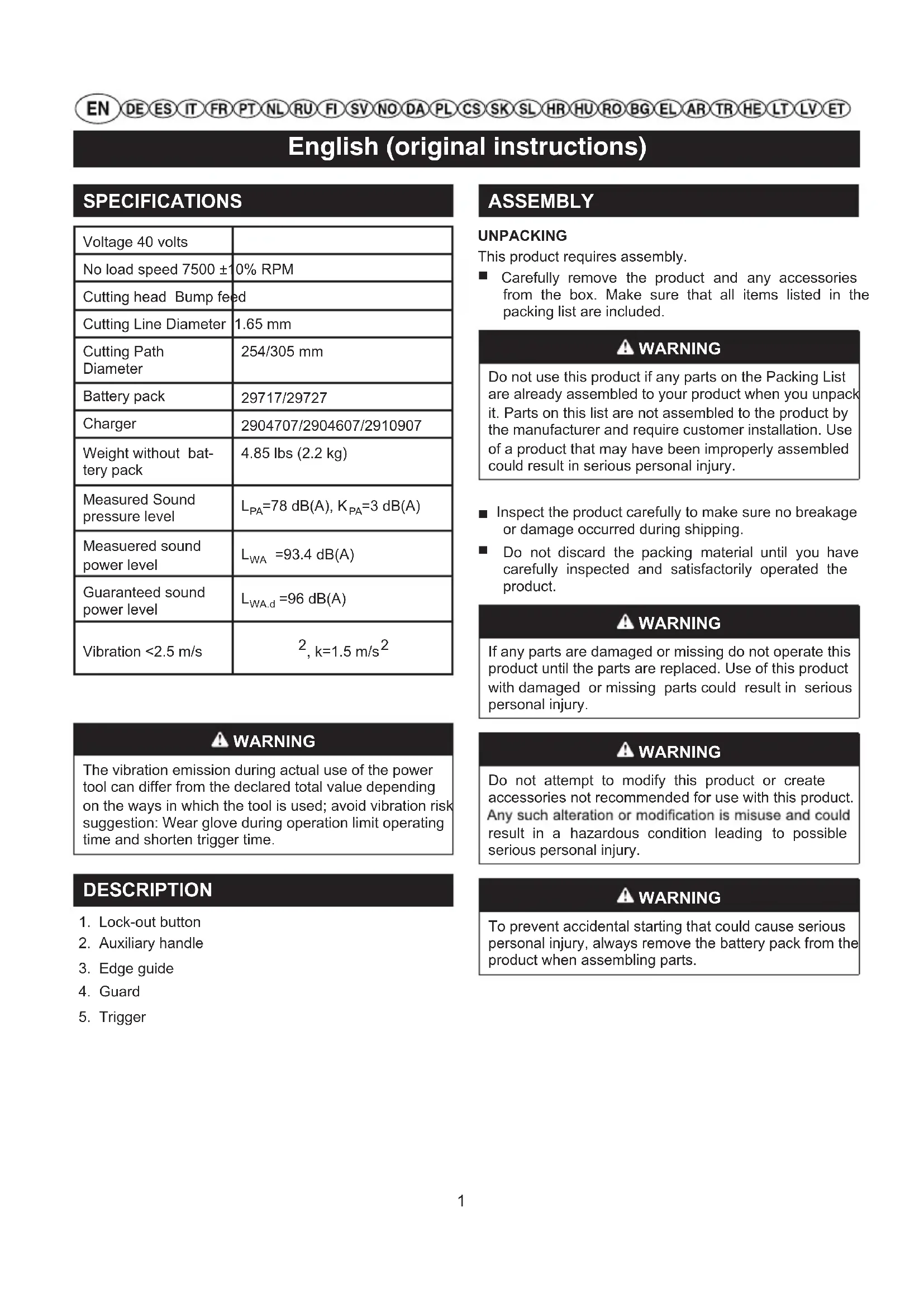
SPECIFICATIONS
| Voltage 40 volts | |
| No load speed 7500 ±10% RPM | |
| Cutting head Bump feed | |
| Cutting Line Diameter | 1.65 mm |
| Cutting Path Diameter | 254/305 mm |
| Battery pack | 29717/29727 |
| Charger | 2904707/2904607/2910907 |
| Weight without battery pack | 4.85 lbs (2.2 kg) |
| Measured Sound pressure level | LPA=78 dB(A), KPA=3 dB(A) |
| Measured sound power level | LwA =93.4 dB(A) |
| Guaranteed sound power level | LwA.d =96 dB(A) |
| Vibration <2.5 m/s | 2, k=1.5 m/s2 |
ASSEMBLY
UNPACKING
This product requires assembly.
- Carefully remove the product and any accessories from the box. Make sure that all items listed in the packing list are included.
WARNING
Do not use this product if any parts on the Packing List are already assembled to your product when you unpack it. Parts on this list are not assembled to the product by the manufacturer and require customer installation. Use of a product that may have been improperly assembled could result in serious personal injury.
Inspect the product carefully to make sure no breakage or damage occurred during shipping.
- Do not discard the packing material until you have carefully inspected and satisfactorily operated the product.
WARNING
If any parts are damaged or missing do not operate this product until the parts are replaced. Use of this product with damaged or missing parts could result in serious personal injury.
WARNING
The vibration emission during actual use of the power tool can differ from the declared total value depending on the ways in which the tool is used; avoid vibration risk suggestion: Wear glove during operation limit operating time and shorten trigger time.
DESCRIPTION
- Lock-out button
- Auxiliary handle
- Edge guide
- Guard
- Trigger
WARNING
Do not attempt to modify this product or create accessories not recommended for use with this product. Any such alteration or modification is misuse and could result in a hazardous condition leading to possible serious personal injury.
WARNING
To prevent accidental starting that could cause serious personal injury, always remove the battery pack from the product when assembling parts.
English (original instructions)
ATTACHING THE EDGE GUIDE See Figure 2.
The edge guide can limit the cutting range of the cutting line and reduce the risk of the rotating cutting line causing damage.
trimmer head.
ATTACHING GRASS DEFLECTOR See Figure 3.
WARNING
Avoid contact with the blade. Failure to avoid contact can result in serious personal injury.
Remove the battery pack.
Invert the grass trimmer/edge to access the trimmer head.
Slide the guard (1) into the slots on the trimmer head.
Align the screw holes on the guard (2) with the screw holes on the trimmer head (3).
Insert the screw into the trimmer head, fastening the guard in place.
WARNING
Do not allow familiarity with products to make you careless. Remember that a careless fraction of a second is sufficient to inflict serious injury.
WARNING
Always wear eye protection. Failure to do so could result in objects being thrown into your eyes resulting in possible serious injury.
WARNING
Do not use any attachments or accessories not recommended by the manufacturer of this product. The use of attachments or accessories not recommended can result in serious personal injury.
ATTACHING THE AUXILIARY HANDLE See Figure 4.
- Ease the ends of the auxiliary handle slightly apart and push it onto the shaft until it snaps into position.
Swing the auxiliary handle in the direction of the arrow and engage it in the required position.
Insert the screw through the holes.
Screw the knob and tighten it firmly.
ADJUSTING LENGTH OF SHAFT (See Figure 5.)
The length of the shaft can be adjusted to suit the height and reach of the user.
Remove the battery pack.
otno ediug egde eht sserp,ediug egde eht esu oT
Hold the shaft firmly.
Depress lock button (1) and hold it in that position.
Pull or push the control handle (2) to the required position.
Release the lock button (1).
Move the control handle (2) back and forth until it engages.
OPERATION
Hold the power head with your right hand on the rear handle and your left hand on the front handle. Keep a firm grip with both hands while in operation. Power head should be held at a comfortable position with the rear handle about hip height. Always operate power head at full throttle. If debris becomes wrapped around the attachment, RELEASE THE SWITCH TRIGGER, and remove the debris.
TO INSTALL BATTERY PACK See Figure 6.
Place the battery pack in the trimmer. Align raised ribs on battery pack with grooves in the trimmer's battery port.
Make sure the latch on bottom of the battery pack snaps in place and that battery pack is fully seated and secure in the trimmer before beginning operation.
TO REMOVE BATTERY PACK See Figure 6.
- Release the switch trigger and lock-out trigger to stop the trimmer.
Press the power button to turn off the trimmer.
Press and hold the battery latch button at the bottom of the battery pack.
Remove battery pack from the trimmer.
STARTING/STOPPING THE TRIMMER See Figure 6.
To start the string trimmer, press and hold the safety lock button (1) and squeeze the trigger (2).
To stop the trimmer, release trigger to stop.
WARNING
English (original instructions)
Noise. A degree of noise from the machine is not avoidable. Route noisy work is to be licensed and limits for certain periods. Keep rest periods and they may need to restrict the working hours to a minimum. For their personal protection and protection of people working nearby, an appropriate hearing protection shall be worn;
Vibration. Always wear safety and anti-vibration glove. Excessive vibration may cause white finger disease or carpal tunnel syndrome. If you notice an unpleasant sensation or skin discoloration during use of the machine on your hands once you stop working. Place an adequate work breaks. And continual and regular users should monitor closely the condition of their hands fingers.
WARNING
Contact with the trimmer cutting head while operating can result in serious personal injury.
CUTTING TIPS See Figure 7.
- Keep the trimmer tilted toward the area being cut; this is the best cutting area.
The trimmer will cut better when moved from left to right across the area to be cut; it is less effective when moved from right to left.
Use the tip of the cutting line to do the cutting; do not force cutting head into uncut grass. - Wire and picket fences cause extra cutting line wear, even breakage. Stone and brick walls, curbs, and wood may wear cutting line rapidly.
- Avoid trees and shrubs. Tree bark, wood moldings, siding, and fence posts can easily be damaged by the cutting line.
ADVANCING CUTTING LINE
While the string trimmer is operating, the cutting line gets worn down and becomes shorter. This trimmer is equipped with bump feed line advancement, which advances additional line once the head is bumped on the ground while rotating. The cutting blade will cut the line to keep an accurate cutting swath.
LINE CUT-OFF BLADE
This trimmer is equipped with a line cut-off blade on the grass deflector. For best cutting, advance line until it is trimmed to length by the line cut-off blade. Advance line whenever you hear the engine running faster than normal, or when trimming efficiency diminishes. This will maintain best performance and keep line long enough to
advance properly.
CONVERTING TRIMMER TO EDGER See Figure 8.
Remove the battery pack.
Depress lock button (1) and hold it in that position.
Rotate control handle (2) 90^ until it engages.
Release the lock button (1).
WARNING
When servicing, use only identical replacement parts. Use of any other parts may create a hazard or cause product damage.
WARNING
To avoid serious personal injury, always remove the battery pack from the tool when cleaning or performing any maintenance.
GENERAL MAINTENANCE
Before each use, inspect the entire product for damaged, missing, or loose parts such as screws, nuts, bolts, caps, etc. Tighten securely all fasteners and caps and do not operate this product until all missing or damaged parts are replaced.
Avoid using solvents when cleaning plastic parts. Most plastics are susceptible to damage from various types of commercial solvents and may be damaged by their use. Use clean cloths to remove dirt, dust, oil, grease, etc.
WARNING
Do not at any time let brake fluids, gasoline, petroleum-based products, penetrating oils, etc., come in contact with plastic parts. Chemicals can damage, weaken or destroy plastic which may result in serious personal injury.
Only the parts shown on the parts list are intended to be repaired or replaced by the customer. All other parts should be replaced at an Authorised Service Centre.
WARNING
To avoid serious personal injury, always remove the battery pack from the tool when cleaning or performing any maintenance.
SPOOL REPLACEMENT See Figure 9.
Use original manufacturer's replacement cutting line for best performance.
English (original instructions)
Remove the battery pack.
Push in tabs on side of spool cover.
Pull spool cover up to remove.
Remove the coil protection from the old spool, and install it on the new spool. Make sure the end of the cutting line is extended from the slots of the coil protection.
Install the new spool so that the cutting line and slot align with the eyelet in the cutting head. Thread the cutting line into the eyelets.
- Reinstall the spool cover by depressing tabs into slots and pushing down until spool cover clicks into place.
CUTTING LINE REPLACEMENT See Figures 10.
Remove the spool from the cutting head.
NOTE: Remove any old cutting line remaining on the spool.
Cut two pieces of cutting line approximately 3m long.
Insert one string into the anchor hole in the upper part of the spool while the other string into the anchor hole in the bottom part of the spool.
Wind the lines clockwise around the spool simultaneously, as shown by the arrows on the spool.
Position the lines in the guide slots.
Install the coil protection on the spool. Make sure the end of the cutting line is extended from the slots of the coil protection.
Place the spring in the trimmer head with its small end upward. Place the spool in the trimmer head. Insert the ends of the lines through the line exit holes in the sides of the trimmer head.
Reinstall the cover onto the trimmer head. Push until cover snaps into place.
STORING THE TRIMMER
Remove the battery pack from the trimmer before storing.
Store it in a place that is inaccessible to children.
- Keep away from corrosive agents such as garden chemicals and de-icing salts.
Store and charge your batteries in a cool area. Temperatures above or below normal room temperature will shorten battery pack life.
Store the battery pack where the temperature is below 27^ and away from moisture.
All batteries gradually lose their charge. The higher the temperature, the quicker they lose their charge. If you store your unit for long periods of time without using it, recharge the batteries every month or two. This practice will prolong battery pack life.
- Secure the trimmer during transport to prevent damage or injury. Clean and maintenance before storage, use of guards on cutting attachments with metal blades. Use of cover for metal blades during transport and storage.
ENVIRONMENTAL PROTECTION
Environmental protection should be a priority of considerable importance when using the machine, for the benefit of both social coexistence and the environment in which we live. Try not to cause any disturbance to the surrounding area.
- Scrupulously comply with local regulations for the disposal of packaging, deteriorated parts or any elements with a strong environmental impact; this waste must not be disposed of as normal waste, it must be separated and taken to specified waste disposal centres where the material will be recycled.
■ Scrupulously comply with local regulations for the disposal of waste materials after mowing.
At the time of decommissioning, do not pollute the environment with the machine, but hand it over to a disposal centre, in accordance with the local laws in force.
English (original instructions)
TROUBLESHOOTING
| PROBLEM POSSIBLE CAUSE SOLUTION | ||
| String will not advance when using the bump-feed head. | String is welded to itself. Lubricate with silicone spray. | |
| Not enough string on spool. Install more string. Refer to string replacement earlier in this manual. | ||
| String is worn too short. Pull string while pressing line release button. | ||
| String is tangled on spool. Remove string from spool and re-wind. Refer to string replacement earlier in this manual. | ||
| Grass wraps around shaft housing and string head. | Cutting tall grass at ground level Cut tall grass from the top down to prevent wrapping. | |
| Motor fails to start when switch trigger is depressed. | Battery is not secure. To secure the battery pack, make sure the latch on bottom of the battery pack snaps into place. | |
| Battery is not charged. | Charge the battery pack according to the instructions included with your model. | |
Only the parts shown on the parts list are intended to be repaired or replaced by the customer. All other parts should be replaced at an Authorised Service Centre.
ATTENZIONE
PNCOEDINHEHNE HANPABJIOUcE CM.Puc.2
Hapablaioa no3Bolraet orpaHnHTb dnaana3OH pe3knpexyue CTpyhbi nCHn3NTb pncNOBpeKDeHHpekyue CTpyHO.
Yto6bI nCnoJIb3oBaTb HAnpaBnIouyU, HaxMnte Ha Hee Ha roNoBKe TpMMepa.
CEOPKA DEΦNEKTOPA TPABBi CM.Puc.3.
OCTOPO)KHO
Avoid contact with the blade. Failure to avoid contact can result in serious personal injury.
BbHyTb akkMyJrTop
IpeBepHnte TpMMep/KpOMKope3, YTo6bI NOJyHTb DOCTyn K rOJOBKe TpMMepa.
BcTaBbTe uTOK (1) Bpa3bEmbHa rOIOBKe TpIMMepa.
CoBmectnte BnHTOBbIe OTBepCTnHa 3aunTHOM npncnoc6JIeHn C OTBepCTnMn DnBnHTOB Ha roJIOBKe TpIMMepa.
BCTaBBTe BnHT B rOIOBky TpMmepa, YTO6bl 3akpenntb 3auNTHOe npncnocobneHne.
OCTOPO)KHO
Co6IIOaIte npedeJIbHyIO octopOxHocTb, daKe ecnBblXopoIo 3NaKOMblc MaunHO. He 3a6bIbaIte, YTO daKe cekyHdHa paCCeHHOCb MoKe IpNBecTu K cepBe3HbIM TpaBMam.
OCTOPO)KHO
BcerIa 3aunuaiTe rna3a.HecobnOJeHne 3ToHOpMbIOMKeT npNBecTN KHaHeceHNTO TKeJIbIX NOBpeKDeHINrna3,BbIbpaCbBAeMbIMnpEdMeTaMNI.
OCTOPO)KHO
He nCnoB3yIte KOMnoHEtBi IIN npHaAdnHexHOCTN, He peKOMeHDoBaHHbIe N3rTOBHTeIeM. IVcNoIb3OBAHne KOMNOHEHToB INI npHaADnExHOCTeE, He peKOMeHDoBaHHbIX N3rTOBHTeIeM, MOXET pNBECTN K TAgKeIbIM TeJIeCHbIM NOBpeXdEHnAM.
YCTAHOBKA BCNOMORATEJIbHOI PYKOK
PucyHOK 4.
Cnerka pa3BedeNTe KOHbI BCNOMOraTeNbHOpyKoTKn BCTOpOHbI HacaNTe HaBaJDoJeJIyKa.
NoBepHnTe BCNOMORAteIbHyO pyKoTky B HAnpaBHeHN, yKa3aHHOM CTpeNkO, n OCTaBBTe B HyxHOM NIOJKeHN.
BctabTe BnHT B OTBePcTna.
HaKpyTnTe pyKy-ФnkcatOp nIIOTHo 3aTAHnTe.
PEYIPOBKA DNIHbI BAJA (cm. puc. 5)
Дина Bana moket perynipobatbca B COOTBETCTBUN CPOCTOM I BO3MOXHOCTaM NOnb3OBATeJIa.
N3BneKeTe aKKMyJnTOp.
Kpenko yapedxmbaTe BaJ.
HaxmTe KhONky 6nOKnpOBKn (1) n ydePknBaIte ee B 3TOM NIOXKeHN.
I Iepemecntte pykoTky ynpaBneHn (2) B HxKHOe noIOXKeHne.
OTnyctnte KhoNky 6noknpOBKn (1).
CdbnHbTe pykoTky npabHeHHa (2) Bnepei Ha3aI,TO6bl OHa 3aΦNkCnpoBaJac.
ENCTBNE
Bo3bMntecb npaBoypyko3a 3aHIOpykoTky TpMMepa, aJeBoi pyko3a nepeHIO.Bo BpeMa pa6oTb npOHO depXnTe TpIMMeP o6eMMn pykAMn. DepxNte TpIMMeR b ydo6Hom dA Bac nOLOKeHN TaK, YTO6bl 3aHna pyKoTKa HaxOdnacb Ha Bbcote 6edpa.MToOpu3OBaHHa rONOBka DOJxHa BcERda pa6oTaB Ha NOHyMoHOCb. Ecnn Ha uTahry ydnnHnTeIaHAMOTaNaCb TpaBa IIN MyCop, OTNYCTITE PbIHAXHBII BbIKHOATEJIb n ydaIInTe IX.
TO INSTALL BATTERY PACK CM.Puc.6.
YcTaHOBtB aKKyMylrTop B TpMMep. BbipOBHrtb BBICTyNAIOoee pe6po aKKyMylrTopa C Na3AMN B 6atapeHOM OTCeke TpMMepa.
Ipeed Tem kak Hauatb nCNoB3ObaT yCTPOINCTBO, y6eNTecb,yTO 3bYIOK 6JOKUPOBKN,pacnoJoxEHbIB B HnXHeu qACTn aKKMyJtopa, IIOTHO BOWeB B COOTBeTCTByUoue OTBepCTne N YTO aKKMyJrTO..
YCTAHOBKA AKKYMUTOPA Cm.Puc.6
OTnyCTnTe KHOKnY 3aNycka n KHOKnY 6JIOKnPOBKn, YTObI OCTaHOBNTpMMep.
HaxmTe KhoNky nTaHn BBkIOuHTe TpMMep.
Haxmnte 3auejky B HxkHeuactn aKMyrTopHoro 6noKa.
CHMMTe aKKMyIaTOpHyo 6aTaapeH CnHCTpyMeHaTa.
3ANYCK/OCTAHOBKA TPMMMEPA Cm.Puc.6.
OTnyctnte KhoNky 3anycka n KhoNky 6JIOKnpOBKn, yTo6bl OCTaHOBNTb TpMMep.
Pycckn (IpebeO d opnHaJIbHbIX nHcTpyKcn)
HaxMMTeu3aueKByHnKHeuactHaKKyMnyTApHoro 6noka.
CHIMMTE AKKYMNIATOPHYIO 6aTapeio C HHTpyMeHTA.

OCTOPO)KHO
YPOBHe bIyMa.Bo Bpempa6oTbI yCTpoiCTBa HeBO3MOxHO n36ExKaTb Obpa3OBAHnIyMa.Ipn BbINOpHEHnIyMhblX pa60Ha onpeJeHHbIX Uyactkax Tpe6yeTcOfOpMJIeHne pa3peuHn I BbINOpHrTbcra OHN MOrTy B yCTaHOBJIeHHbIe nepIOdbl cyTok.Kpome o6a3aTeJbHbIX nepepbIBOB B pa6oTe M OXET NOT pe 6o BA tBCra N O rpaHnUeHN e npOdoJIHTeJIbHOCTn pa60bl.ДЯ obecneeyHn IepcoHaJIbHO 3aUNTIb I 3aUNTIb HaxOJaUNxC8 B HeNoCpeDCTBeHHoB 6n3OCTn IIODe HEO6XoIMO mONb3OBaTb HaJIeKaaUne CpeDCTBa 3aUNTIb OPraHOB cIyxa;
Bn6paqna. Bcerda nCnoIb3oBaTb 3aunTHbIe aHTNB6paQIOHbIe nepaTk.N36bIToHbI ypoBeH bN6paQmOKeT Bbl3BaTb N6peJHHeHne naIbueB nnCnDpom 3anrCTHO KaHaJa.Ecn BO Bpem IcNoIb3oBaHny yctpoIcTBa NOBnEeTc HnpeJTHoe no6JeHHeHne Koxn pyK, cJeDuYet HEmeJHHeHn npepBaTa pa60Ty. Heo6xOIMO yctpanBaTb nepepbIBbHa OtDbIX. Ecnn Bbl peryIpyHo nONb3yeTeCb yctpoIcTBOM, qacto KOHTPOINpyTe coCTOAHNe naJIbueB pyK.

OCTOPO)KHO
CnyaHbIKoHTaKTcpeKyuIeIroNOBKOITpMMepa MOKeT pNBecTu K TaeKeJIbIM TeJeCHbIM NOBpeXDeHnM.
PEKOMEHDAUIN NO BbInOJIHEHIO PE3KN CM.
Puc. 7.
ДерхиTe TpIMMep NOД HaKJIOHOM K ПLOCKOCTN CTpNKKN, 3TO NOJOXKeHHe ABJAreTc ONTImaJIbHbIM.
BbIOCTHHeTe lyuXn pe3yNbTaTOB ba6oTe,ecn 6yDeTe DnRaTb TpMMep CneBa HAnpaBO; cTpNkKa 6yDet MeHee 3ΦΦeKTHBHO npn DBHXeHN TpMMepa cnpaba HaJeBO.
IcnoJb3yInTe dIa cTpnKKn Kpaan pexkyue HHTN; He BBODnTe pexyuio rONOBky rny6oko B TpaBy.
Pn HataKnBaHn Ha KOnIouyIO npoBOLOky n OrpaDbI yckopraTcN3Hoc pexyueHHTN, BnNoTb Do ee pa3pbIBa. KamHN, Knpnnu, DepeBO npnbOJr K 6bictpomy N3HOcy HNT.
H36raTe KOtakTa C DepeBbMa N KcyTAM. Pexyua HHTb MoKeT HaHeCTN NOBpeXeHn Kope DepeBbeB, DepeBaaHHbIM CTPOnteBbHM DeTaIaM, YAcTAM NaHeNbHOoBKN uN3rOpOdM n3 WtAkETNuKa.
ABTOMATUeCKN 3ANYCK PEXUYUEH HNTI
BoB BpeMa pa6oTbI cTpYHHoro TpIMMepa, pexyua
CTpyHa n3HaunBaETcN n CTAHOBNTcK OPOe. 3TOT Tpmmep OCHaueH CNCTeMOB BbIDBnXKeHN cTpyHb, 6JarOanpa KOTOpO CTpyHa BbIDBnraeTCR, KOrda rONOBKa ydapreTcN O 3emnIO np BpaueHN. CneunaIbHbI HOK o6pe3aET CTpyHy DO HxKHOJ DnHbI.
PEKYLIMHOHXHNTI
YcTpoiCTBO OCHaUeHO pe3c0m HnTn, YcTaHOBHeHHbIM Ha DeoJIeKTope TpaBbI. DnO NTMaJIbHOrO BbIOJINHeHnpe3a pa3MOTaTB HHTb HA HyXHyIO dInHy. BbIOJINHTb pa3MOtky peKyuSeH HNT, ecn DBnraTeNb HauHHaET BpaUaTbcr CoCKOpocTbIO, npeBbIshaUeH HoPMaJIbHyIO, INNecn 3aMeueHO NOHNKeHne IPOUN3BOOnTeJIbHOCTN CTpnKKn. 3TO IO3BOJNT NODepxNBaTb ONTMaJIbHyIO npON3BOOnTeJIbHoCTb yCToPoiCTBa n npabINbHyIO dInHy peKyuSeH HNT.
ПЕОБРАЗOBAHNEТРИММЕРABYCTPOICTBOДЛЯOBPE3AHNYKPOMOKc.Puc.8.
I3BJIeKInTe aKKymyTApTOp.
HaxmTe KhoNky 6nokpOBKn (1) n ydepXnBaTte ee B 3TOM NOIOXKeHN.
■ NobeprHnte pykoTky ynpabHeHn (2) Ha 90°, noka OHa He 3aФнкpyeTc.
OTnyctnte KhoNky 6JIOKnpOBKn (1).

OCTOPO)KHO
B cnyae 3ameHb IcnoIb3oBaTb NckIIOUHTeJIbHO
fnpMeHHbe 3anaChbIe yactn. IcnoIb3oBaHne npyHX
KOMIOHETOB MOKeT IpeICTaJIbTb ONaCHOCTb IIN
Nocnykntb npuHNOI NOBpeKdEHNr yCTpOInCTBa.

OCTOPO)KHO
Bo n36exaHne pncKa noIyueHnra TjKeBbIX
NoBpeXeHn cIeDyET o6aTeJIbHO n3BNeKaTb
aKkyMylrTop n3 yCtpoiCTBa BO BpeM erO YNCTKN
n npu BBInonHeHHn IIO6bix pa60T NO TexHnueckOMy
o6cnyxHBAHIO.
OBUEETEXHNUECKOE OBCJNYKBAHNE
Pepa KaKdIbIM nCNoJIb3OBAHHeM cIeDyET
npokohpOIpOBaTb yctpoiCTBO DnA o6hApyKeHnnoBpeXdeHn, OTCyTCTByIOxN nnOcna6neHHbIXaCTe, KaK, HAnpIMep, BnHTbl, RaKN, 3axMMbl N T.D. HadJexKaUmO6pa30M 3aTaNHe BCE KpeJexKhbleDeTaNN n He npINBOOnTe yCTpoiCTBO B DeIeCTBnE Do Texnop, noka He 6dyT 3ameHeHb BCE OTCyTCTByIOxNe nnNOBpeXdeHbIe YactN.
He nCnoJb3ObaTb pactBopnteIIN JnYnCTKn NnactNKOBbIX
Pycckn (IpebeO d opnHaJIbHbIX nHCTpyKcN)
chaTeBolbwaJyactbIpaCTIKOBbIX MaTePnaNoB MoKet 6bItb IOBpeXdeHa IMeIOUIMnC8 B npOdaKe paCTBOpHTeYAMN. NcnoB3OBaTb YnCTyU BeToUbIy ydaJIeHnI rpa3N, nbIIN, MacNa, rycToH CMa3KN T.D..
OCTOPO)KHO
TOPMO3HONJNDKOCTN,6eHN3nHa,HeoTeXmMuecknx npOdyKTOB, npOHkaOuX Macen n T.n. TaKe XMHmueckne npOdyKTBI MoryT NOBpeNTb,OCnA6NTb Hnnpa3pyuHTb PnactNY, yTO MOKeT pINBeCTN K NnHbIM TpaBMam PemOnTy nn 3ameHne NoIb3OBaTelem NOJExKaT ToIbKO KOMNoHEtBi, BXOJaUe B CnICOK 3anachbIX qacte.Bce dpyrue qactn DoJIxHbI 3aMeHrtbCABTopn3OBAHHbIM cepBnCHbIM cHTpOM.
Дя peMOHTa И 3aMeHb MOxHO INcNoIb3OBA Tb TOnbKO DeTaN, Yka3aHHbIe B CnNcKe DeTane. 3aMeHa BCex dpyrnx DeTanei DoJXHa npOn3BODITbcR aBTopu3OBaHHOM cepBnCHOM ueHTpe.
OCTOPO)KHO
Bo n36exaHne pncKa noIyueHnraTaeKbIX
noBpeXdEHH cIeDyET o6raTeJIbHO n3BNeKaTb
aKKymJrTOp n3 yCtpoiCTBa BO Bpem erO qNCTKn
n npn BbINOJIHeHH IIO6bix pa60T NO TEXHnueckOMy
o6cIyKINBaHIO.
3AMEHA KATYLKNI CM.Puc.9
IVcNoJIb3OBA Tb NCKIHOHTeJIbHO OINHOUYo peKyuH HHTb C DnAmETpOM 2 MM.
N3BneKeTe aKkMyIaTOp.
HaxaTb BHyTpB KpbIbIuKn, HaxoJyIuecra no 6okam KpbIuKn KaTyuKn.
IINrCHrTnKpbuKnKaTyuKnNotaHybeeBbepx.
BbHyTb CTapyo KaTyuKy.
IpeyctahOBKOHOBOKATyUKNY6eINTbcra,HTbBCTaBnEHaBn3HaHOBOKATyUKe.Y6eINTbcra,TO KOHePexKyUeHNTHN BbIXoNTn3n3aHaOKOJIO15cm.
YCTAHOBHTb HOByIO KAtyWky TaK, YTO6blpeKyuaa HnTb n na3 6blIN BbyIPoBHeHbI NO npoyuHHe B pexyueen roNoBKe. PpOncyTnB HnTb B npoyuHy.
HaTeb KpbIuKy Ha KaTyuKy, BCTaBn R3bUKn B Na3bl Haxmam Ha Hnx Do NOnHou PnKCaun KpbIuKn.
3AMEHA CTPYHbl Cm. Puc. 10.
BbHbTe KaTyKu n3 roJIOBKn CTpyHbl.
PIMMEAHNE CHINMITE c KaTyuKn OCTaTKn CTapOu CTpyHbl.
OtpexbTe DBe cTpHybl dInHoi OKoNo 3M kaXda.
Bctabte Ondy ctpyHy B aHkephoe OTBepCTne B bepxHeuactn uynbKn, a dpnyo ctpyHy - B aHkephoe OTBepCTne B HnKHeuactn uynbKn.
OndHOBpemeHHO HamotaTe CtpyHbI no yacBOB CTpeJIke BOKpyr 7nynbKn, KaK NOKa3aHO CtpeJIkAmn Ha 7nynbKe.
PacnoIoxKeIe Nccky B HnpaBnaIOxN X BbIeMKaX.
YcTaHOBInTe 3aunTy Ha KaTuShKy. Y6eDnTeCb, YTO KOHLbI JeCKN BbITraHyTbI N3 BblEMOK Ha 3aunTe KaTuShK.
YcTaHOBnTe npyKHy B rONOBky TpIMMepa MaNeHbKM KOHLOM BBepx. YcTaHOBnTe KaTyWKy B rONOBky TpIMMepa. IpoDeHBe KOHcJI JeCKn Hepe3 OTBepCTna Ha 6OKOBbIX CTOpOHAX rONOBKn TpIMMepa.
YcTaHOBnTe KpbIuKy Ha rOIOBky TpIMMepa. PnIXMnTe, YTO6bl KpbIuKa 3aФИKcIpuBaIacbHa MeCTe.
XPAHEHNE TPNMMEPA
Ipeed noctaHOBkoHa XpaHeHne BbHyTb N3 TpMMepa aKKyMyJrTop.
I NomeCTnTB yCTpOuCTBO B HeIOCTynHoe dTn DTee MecTo.
He depkaTbe erO B6n3n OT pa3bEaHouX XmMuecknx BeueCTB, HApPImep XmMuecknx CpeIcTB dIpa CaIOBOIDCTBa nn CoN n Iy6OpKn Chera.
XpaHntb n 3apKaTb aKKMyJrTopHyo 6aTaapeo BnpoXnHOM MceTe. Pn Tempeatype Bbiue nn Hnke HopMaJIbHOI Tempeatypbl OkpyKaIOuIe CpeDbI COkpaUaTcA cPOK cnyKbI aKKMyJrTopa.
XpaHntb aKKMyJrTop npu TemnepaType Hxke 27^ n B MecTax, JINUeHHbIX BJIaXHOCTN.
Bce akymyIaTopb co BpeMeHem TepnoT 3apn. Yem Bblwe TemnepaTypa, Tem 6bictpee akymyIaTOp TepraeT 3apn. B cnyae dnttehoro HeucnoJb3oBaHna ycTpoNCTBa nO3apxKaIte akymyIaTOp pa3 B Mecau nn KaXdbie Dba Mecya. 3TO nO3BOJNT npOdnTb cPOK cnYk6bl akymyIaTopa.
Bo Bpemr TpaHcnpTnPOBKn DOJXHBIM 6bpa30m 3aKpeNITe Tpmmep, YTO6bl N36ExKaTb ero nobpejdeHn. Ipeed nocTaHOBkoi Ha xpaHeHne NOUcHTe yCTpOInCTBO H BbINOHNITE Heo6xODnOoe TexHueckoe OScnykBaHne, 3aunTe MeTaNueckne HOx. NcNoIb3yInTe HAdnEkaune Yexbl DnA MeTaNuecknx HOKe npn TpaHCnpTnPOBKe IN XpaHeHH.
OXPAHA OKPYKAAIOUEN CPEbl
OxpaHa OkpykaHoueI cpeBIOJXHa YBJIbTc8 CyueCTBeHHbIM IN nepBOoUepeIDhbIM acNEKToM npINoJIb3OBaHIn MaunHO, BO 6naro YeJIOBeYeCKOrO
Pycckn (IpebeO d opnHaJIbHbIX nHCTpyKcN)
obueCTBaNOKpykaUoSeCpeblBKOToPoMBI KINBE.M.CtapaTecbHe6ecnokoutbOKpykaUOx.
Ctporo co6nOdaTe MeCTHbIe HOpMbI no yTINN3aUNy YNAKOBKN, MaceN, 6eH3nHa, fNtBtpoB, NOBPexDeHHbIX YAcTe NNN IIO6bIX 3JIeMeHTOB CO 3NaHTeNbHbIM BInrHHeMa OKpyKaIOUcYIO CpeDy; 3TN OTXODBI He DOnXHBi BBipacBIBaTBcR C 6blTOBBIM MycopOM, a Co6npaTbcR OTdEhBO INpePaBaTbcRA B CneuAnbHbIe CEHTpbI C6opa OTXODB, BInONHraIOUme INx nepepa60Ky.
Ctporo co6nOdaTe DeIcTByIOuNe Ha MeCTHOM ypoBHe npabuna no BBiBO3y OTXoIOB pa6oTbl.
Iocne 3aBepWeHn Cpoka CnyK6bMaunHbHe Bb6paCbBAHTe ee, a o6patntecb B cHTp c6opa OTXoOB B COOTBeTCTBn C DeiCTByIOuIM MeCTHBIM 3aKOHOdaTeJIbCTBOM
OBHAPYXEHNE N YCTPAHEHNE HENCPABHOCTE
The vibration emission during actual use of the power tool can differ from the declared total value depending on the ways in which the tool is used; avoid vibration risk suggestion: Wear glove during operation limit operating time and shorten trigger time.
KUVAUS
GENERELT VEDLIKEHOLD
Use original manufacturer's replacement cutting line for best performance.
Odpojte vlaknovy striha.
Stlacte smerom dovnuta klapky na bokoch ochranného krytu cievky.
Vytiahnite kryt cievky, aby ste ho odstranili.
Pri instalacii novej cievky skontrolujte, ci je vyzinia struna prevalcena cz otvor novej cievky. Preverte, ki konce silonu vycnievaju circa 15 cm cz otvor.
Instalujte novú cievku tak, aby vyžínacia struna a otvor boli zarovno s okom na rezacej hlave. Prevlečte silon cz Oko.
Znovu instalujte ochranny kryt cievky. Zatlačte klapky do strbin a tlačte ažPokial sa kryt cievky nevotkne do dražok.
IPOZAPTHEH BOHOTIKHE XEIPOAABHE Bλ.
Eikova 4.
AvoiEeAaPpTa aKpa Tng Bonntikns XepoalaNc Ka TIEOTe Tnv Tavw OToV aOva, Expi va aopaaiaei oE autn tn theon.
Ieipotpetyte n Bononntikn xeipoaan otnykateuovan Tou baouc kai otaepoioinote nV otny aattouuev n Eo.
Iepaote Tn 3iδa aTIO Tc oTc.
IPOZAPMOH MHKOYTOY AIONA (Bλ. Eikova 5.)
To nkoosou aoxoavipooopoei o uoc kai tny ikavotnta ektaonssou xphotn.
Apaipote tny mntapia.
KpatnoTe i t ToV aEova.
Pntote to koupi KkEiDomega (1) kai kpatote to patnevo.
TpaBnTe n wnoTe tn xeipolaan xepiou (2) otnv eTIuunr thc.
ATελεuθερωτε TO KOUμπI Kλειδωματος (1).
MetakivnoTe Tn xeipolaBn xeipioou (2) mtpootka n iou mexpi va aopaioi
AEITOYPTIA
Kpatnate Tnv Kepaan me to dee iocxepi otyn niow aai KaT o apioTepo oac xepi otny uPooTivn aai. Kpatate ka kai me ta duo xepia ooo xpnoioToie To npxavna H kepaan npttei va biatnpetai oe avtn theon, e Tnv tiaw aBn nepitou sto uoc twy oopw. Aeitoupyeire Tavta Tnv kepaan me tianpntaxutnta. Av tuixoov unoalemuata yupw anto te xaptnua, AΦHTE TON AIAKONTH ENEPTOIHsE Kai aapoeTe Ta.
IIA THN TOINOOTEHsM NITAPIA2 B. Eikova 6.
ToTOnoTeIaTe TnV mTaApia OTo KOnTIko mXavna. EuOuypaumote Ta avuWmuEva ywOoiDi aOnv mTaTApia Me Ta auLakia Otn Theupa mTaTApiac Tou KOnTIkoU mXavHauoC.
BeBaiWteIe oTI to ayKIOtpo OTn baoTnC mTATAPIac KAEIDWEI OTN TEON TOU KAI OTN MNTAPIA Exi TOTTOETNI KALA KAI E aOaPaeia OTO KOTTIKO uXavma, PPIV EKIVNOETE Tn XpnoTou.
IIA THN AΦAIPEESH THE MNATAPIA Bλ. Eikóva 6.
1s 1s 1s 1s 1s 1s 1s 1s 1s 1s 1s 1s 1s 1s 1s 1s 1s 1s 1s 1s 1s 1s 1s 1s 1s 1s 1s 1s
A
1 1
#
Uusale. Caoa oio Uo a Uuaiaole J spu 10001, uui eue cagua Uauu uuae EUs Uus 10001 uuuu uuuu uuuu uuuu uuuu uuuu uuuu uuuu uuuu uuuu uuuu uuuu uuuu
CIM BICME MAKINESINI DEPOLAMAK
wnnnn nn nnnn nn nnnn
n nn nnnn nn onn nn nn nn nnn
nnn nn nn
.6 1
.(2)ann by yn
annnnn nn nnnn nnnn nnnn nnnn
A
y nnnn nn nnnn nn nnnn nn nnnn nn nnnn nn nnnn nn nnnn nn nnnn nn nnnn nn nnnn nn nnnn nn nnnn nn nnnn nn nnnn nn nnnn nn nnnn nn nnnn nn nnnn nn nnnn nn nnnn nn nnnn nn nnnn nn nnnn nn nnnn nn nnnn nn nnnn
A
n nn nnnn nn nnnnnnnnnnnnnnnnnnnnnnnnnnnnnnnnnnnnnnnnnnnnnnnnnnnnnnnnnnnnnnnnnnnnnnnnnnn
A
yyn ynn n nn noiin noynn nnyn nn n nn n nn n nn nn nn nn nn nn nn nn nn nn nn nn nn nn nn nn nn nn nn nn nn nn nn nn nn nn nn nn nn nn nn nn nn nn nn nn nn nn nn nn nn nn nn nn nn nn nn nn nn nn nn nn nn nn nn nn nn nn nn nn nn nn nn nn nn nn nn nn nn nn nn nn nn nn nn nn nn nn nn nn nn nn nn nn nn nn nn nn nn nn nn nn nn nn
A
ninn nni nnn nnn nnn
Tnn nnin
Tn n nn nn nn nn nn nn nn nn nn nn nn nn nn nn nn nn nn nn nn nn nn nn nn nn nn nn nn nn nn nn nn nn nn nn nn nn nn nn nn nn nn nn nn nn nn nn nn nn nn nn nn nn nn nn nn nn nn nn nn nn nn nn nn nn nn nn nn nn nn nn nn nn nn nn nn nn nn nn nn nn nn nn nn nn nn nn nn nn nn nn nn nn nn nn nn nn nn nn nn nn
n nn no
innnnn
on 1
nnn nnnnnnnnnnnnnnnnnnnnnnnnnnnnnnnnnnnnnnnnnnnnnnnnnnnnnnnnnnnnnnnnnnnnnnnnnnnnnnnnnnnnnnnnnnnnn
n nn nnnnnnnnnnnnnnnnnnnnnnnnnnnnn
.10n7 nyn 97nn noon nn
yon nn ynnnnn nn nnnnnnnnn
inn nn nn on .inn nn nnn nn nnn 70n
nwnnnnnnnnn
.8nnn7 nynn nn no
n7 nnn nn 7y hnon noa nx uinn
09-2 (2) n7n nT 10
. tyinn
(1) n
10 1n n
no no7n
All new Greenworks Tools machinery is supplied with a 2 year parts and labour warranty from original date of purchase. A 30 day warranty is available for machines used professionally as Greenworks Tools are designed primarily to be used by DIY consumers.
This warranty is non-transferable.
LIMITATIONS
This warranty applies only to defective parts/components and does not cover repairs due to:
- Normal wear and tear.
- Routine tune up or adjustment.
- Damage caused by improper handling/abuse/misuse or neglect.
- Overheating due to lack of maintenance.
- Damage due to fittings/fasteners becoming loose/detached through lack of maintenance.
- Damage caused by cleaning with water
- Machines serviced or repaired by non-authorised Greenworks Tools service centres.
- Machines incorrectly assembled or adjusted.
- Damage caused by improper use of the machine.
- Damage caused by improper winterisation (pressure washers)
-
Items considered as consumable parts are not normally covered by the warranty, including but not limited to:
-
Batteries
Electric cables - Blade and blade assemblies
Belts -
Filters
-
Certain products may contain components such as engines, transmissions from an alternative manufacturer, these items will be subject to the appropriate manufacturer's warranty policy except where Greenworks Tools Europe GmbH agrees to underwrite any claims outside the said manufacturer's warranty period.
- Second hand goods are not covered under this warranty policy.
- The fitting of spares, replacements or extra components which are not supplied or approved by Greenworks Tools Europe GmbH.
Warranty
To claim a warranty on any product under this policy a proof of original purchase is required. Credit card statement do not qualify as sufficient proof of purchase. In the first instance of a warranty event occurring the consumer should return the product to the original place of purchase with their proof of purchase. The machine will be sent to our central service facility and an inspection made. If the machine be found to be at fault it will be repaired and sent back to the address of the consumer free of charge. Machines that retail for less than €100 euros including sales taxes will generally be replaced.
If the central service facility finds that machine is not found to be at fault then the consumer will be advised they will need to pay for the cost the repair.
This warranty policy is subject to change from time to time to accommodate the needs of new products. A copy of the latest warranty policy will be available at www.greenworkstools.eu.

TapaHOnHH npaBnHa Ha Greenworks Tools 3a camoDEnH MaHNH
NEPNOHATAPAHUYRA
Bcunn Maunn Ha Greenworks Tools ce npedoctabr c 2-rounha rapaunna 3a cepbnHa deHooT neepbHn qactn, chntaHO OT daTata Ha 3akynbahe Ha npdykTa. PnpocTabra Ce camo 30-dHeBH aRaapanu 3a npocecnoHAn H3non3BaHne Maunn, 3auTo npodytme Ha Greenworks Tools ca npdHa3hauen nppeDmH0 3a KIneHTn, paObeTnc CamoJEnn Maunnn. Hactoata rapanu He moke da ce npexbprna.
OTPAHNUEHHN
Hactoata rapaHcna e BaInHa cAmO 3a DepeKTHn qactN/ KOMnoHEHTn H He NOKPbA peMOHTn, NopoEHN OT: 1. HopMaIHO n3HOCBaHe n AmOpTH3aUa.
- PyTHHHH HAcTPOKIN INI N DeHOCHT No perynpaHe.
3.Пов体育场пчненOT He npabnno6opabHe/3IoynoTpe6a/ rpeuho n3NoI3BaHe nnpraBa Ha He6peXHocT. - IperpraBaHe npaDi NoWa NODpbXkKa
- NopBpei npaPi pa3Xna6eHn/pa3KaueHn cHaKn nNcKpeNTnHn eIemEnT B CneDCTBn Ha Noa PndpBxka.
- NOBpeH, npuHHeH B CJIeCTBHe Ha NoUcTBAHe C BOJa.
- MaunHH, 06cnyKbAHn Hn peMOHTnpaHn OT cepBn3n ceHTpOBe, KOHTo He ca oTOpN3npaHn OT Greenworks Tools.
8.MaunHnKoTcaccrno6eHNnnpeynpaHn HnnpabuHNO. - NOBpeH, npoOeHn OT HnnpaBnJIHO 6opabeHe c MaunHaTa.
-
NOBpei, nopoDeHn OT HnpaBnHIO 3aImBaHe (BOOcTpyKn)
-
EInemEnH, KOnTo ce cCHTaT 3a KOHCymATNB, HO O6nKHOBHe He Ce NOKPBAt OT rapaHuaT, BKIOUHTeJIHO (HO He caMo):
-Батурш
EneKtpueecknKa6eJN
- OctpneTn KOMNNEKTN OCTPneTa
Pembun
-ФИNTPn
- NaTpoHHnN nIbpxaun 3a HcTpymeHTn
-
HЯко npodykTN MoRAT da cbdbpxkT KOMNoHEHTN (Hapmep DbrarateMn, TpaHCMncn) OT dpyrN pOn3BOJNTeN - 3a Te3n eIemEtN ca Bcna rapaHIOHNHTe ycNOBnHa CbOTBeTHn npOn3BOJNTeOcbH bClyaTe, Korato Greenworks Tools Europe GmbH ce cbfNaac Da nokPmeJeTne, KOtTo He ce nokpnbat OT rapaHIOHNHNE nepnoD Ha To3n npOn3BOJNTeN.
-
CToKn Btopa ynoTpe6a He ce nokpmbat OT hacToaTa rapaHua.
- MoTHIpaHTo Ha pe3epBn YacTn, 3aMeCTBaUu ININ DOnbNHTeHN KOMNoHEHTN, KOTo He ca IpeOCTabeHn ININ ODo6peHn OT Greenworks Tools Europe GmbH.
Tapaun
3a npedraBaHe h rapaHnoHnck 3a dahen npdykt Tpr6Ba da ce npdeocTabn Doka3aTeNTBO 3a nbpBOHaauHNO My 3aKnyBaHe.
N3BneueHnHTAOT KpeDTHnKAPTN He npdeCTabnBaT BAnHIO
Doka3aTeNTBO 3a 3akynBaHe. PnP nbpBOTb B3hKNBa HcNObHe,
No3BOBaIaO npdeRBABaH ra paHUNoHnCK,KnHeHTb Tpr6Ba Da
3aHece npOyKTa Ha MCTOTO Ha HerOBTO nbpBOHaanHO 3aKnyBaHe,
KbTeTo Tpr6Ba Da npdeocTabn Doka3aTeNTBO 3a 3akynBaHeTo.
MaunHaata 6bDe n3npaTeHa Do hauinr IraBeH cepBn3eH ueHTbp,
KbTeTo 6bDe n3BbpuHnHcNeKuHa. Ako CE yCTahOBn fapnuH
deΦeKt N MaunHaata, Ta 6bDe 6e3PiAtHO pemOHtnpaHa n
InnpateHa o6patHo ha aDpeca Ha KIneHTa. MaunHnte Ha na3apHa
ctOIOCT NO 100 Ebo (BKN.DaHbK npOdaX6a) O6knHObeHo 6bDaT
NoDMehHN C HOBn.
Ako haunr rnaBHe cepBn3eH ceHTbpeYcTaHOBN pa6pnHH deFeKTn no MaunHaT,KnneHbT ue 6bde yBeDomeH,Ye Toi ue TpBa da 3annat paxOdnte No peMOHa Ha npOdyKTA.
HactoInte rapaHIOHH npaBnla MoT a 6bDat npomeHa n nepnoDnHO, 3a da 6bDaT aKtYanHO aadantnpaH N kM HOBNTe npodykTN. Konne Ha Na-AkTaYAnHTe rapaHIOHH npaBnla e HanaHNo ha aDpec www.greenworkstools.eu.

Ioiitik yyyuno ng ouke uuv maotopepaTOG Greenworks Tools
NEPIOAOEETHYHHE
Ola ta vεa μηxavnμata nC Greenworks Tools ouvodéuovtai ato
eyyun2 2 etuv yia ta εgapntμya taka epyatika touc, aTIO Tny
apxikn ηeepounvia ayopac. Eyyun3 30 nepwv napexetai yia
μnxavnμata tou XPnoiμotiouovtai Etayeeμatika, kaωc ta
tpoiovta nC Greenworks Tools ateuehuvovtai kupicσ e paaitexveC
katavaawtεs tpoiovtuv maatopεμatoc.
H eyynon eivai μn μetaβiaiμn.
NEPIOPIEMOI
H TAPOUSA EYUNAN IOXUEI MOVIOYA EALTUMATKA EApTmuata/EVOTNTC KAI DEV KAUTTEI ETIOKEUEC TIOU OPeIAovTAI OE: 1. DuioAloyik pOpa.
(DIY) duiy iie Greenworks Tools 4
C 52
e 14
Greneworks Tools 30 32
Greenworks Tools 1
. (DIY)
#
j 1
- 业
- 2 < 3
- .7
Greenworks Tools
.8.
.9.
0. (shail)
Jill Jie 1520 Lg jiaaiyale gao y asiee e jai 11
y
New Greenworks Tools
"
nnnn n
n nn nnnn nnnn nnnn nn nnnn nn nnnn nn nnnn nn nnnn nn nnnn nn nnnn nn nnnn nn nnnn nn nnnn nn nnnn nn nnnn nn nnnn nn nnnn nn nnnn nn nnnn nn nnnn nn nnnn nn nnnn nn nnnn nn nnnn nn nnnn nn nnnn nn nnnn nn nnnn nn nnnn nnnn nn nnnn nn nnnn nn nnnn nn nnnn nn nnnn nn nnnn nn nnnn nn nnnn nn nnnn nn nnnn nn nnnn nn nnnn nn nnnn nn nnnn nn nnnn nn nnnn nn nnnn nn nnnn nn nnnn nn nnnn nn nnnn nn nnnn nn nnnn nn
#
n nn nnnnnnnnnnnnnnnnnnnnnnnnnnnnnnnnnnnnnnnnnnnnnnnnnnnnnnnnnnnnnnnnnnnnn
- .2. m
3.nnnn
4.nnnn 70
.50in
.
.6
.7 Greenwork
. Tools
.8.124
9.123456789
10 (ynnna)
,nnnnn nn nnnn nn nnnn nn nnnn nn nnnn nn nnnn nn nnnn nn nnnn nn nnnn nn nnnn nn nnnn nn nnnn nn nnnn nn nnnn nn nnnn nn nnnn nn nnnn nn nnnn nn nnnn nn nnnn nn nnnn nn nnnn nn nnnn nn nnnn nn nnnn nn nnnn nn
27 × 27 × 27 = 1275
n7710
2017·52
DNON
17nnnno09n
n nn nnnn nnnn nnnn nnnn nnnn nnnn nnnn nnnn nnnn nnnn nnnn nnnn nnnn nnnn nnnn nnnn nnnn nnnn nnnn nnnn nnnn nnnn nnnn nnnn nnnn nnnn nnnn nnnn nnnn nnnn nnnn nnnn nnnn nnnn
Greenworks ynnn nn nnnn nn nnnn nn nnnn nn nnnn nn nnnn nn nnnn nn nnnn nn nnnn nn nnnn nn nnnn nn nnnn nn nnnn nn nnnn nn nnnn nn nnnn nn nnnn nn nnnn nn nnnn nn nnnn nn nnnn nn nnnn nn nnnn nn nnnn nn nnnn nn nnnn nn
nIN nn
11
XW IN NnN7 07nNnNnNnNnNnNnNnNnNnNnNnNnNnNnNnNnNnNnNnNnNnNnNnNnNnNnNnNnNnNnNnNnNnNnNnNnNnNnNnNnNnNnNnNnNnNnNnNnNnNn
Greenworks Tools Europe GmbH by wink
#
y
n 100 nnnnnnnnnnnnnnnnnnnnnnnnnnnnnnnnnnnnnnnnnnnnnnnnnnnnnnnnnnnnnnnnnnnnnnnnnnnnnnnnnnnnn
197n nyn 70
y nynn npnnn nn nnnn nnnn nnnn
11nnnnynxohy
n .a. an nnnn nn nnnn nnnn nnnn nnnn nnnn nnnn nnnn nnnn nnnn nnnn nnnn nnnn nnnn nnnn nnnn nnnn nnnn nnnn nnnn nnnn nnnn nnnn nnnn nnnn nnnn nnnn nnnn nnnn nnnn nnnn nnnn nnnn nnnn nnnn

"Greenworks Tools" buitines paskirties irenginiu garantijos taisykles
GARANTIJOS LAIKOTARPIS
EC DECLARATION OF CONFORMITY
Manufacturer: Changzhou Globe Co., Ltd.
Address: No.65 Xinggang Road Zhonglou Zone Changzhou, Jiangsu 213000 P.R.China
Name and address of the person authorised to compile the technical file:
Name: Peter Soderstrom
Address: Hjortronvagen 3, 555 93 Jonkoping, Sweden
Name who compile the technical file:
Herewith we declare that the product
Category: 40V Front Mount Brushed Gear Reduced Trimmer Model: 2105407
Serial number: See product rating label
Year of Construction: See product rating label
■ is in conformity with the relevant provisions of the Machinery
Directive 2006/42/EC; EMC directive :2014/30/EU; 2000/14/EC
(Noise-Directive) incl. modifications (2005/88/EC)
And furthermore, we declare that
the following (parts/clauses of) European harmonised standards have been used
EN 60335-1; EN 50636-2-91; EN 55014-1; EN 55014-2
EN ISO 3744; ISO 11094
Grass Trimmer
Measured sound power level
93.4 dB(A)
Guaranteed sound power level
96 dB(A)
Conformity assessment method to Annex VI/ Directive 2000/14/EC
Place, date: Changzhou, 14/12/2016
Signature: Ted Qu Haichao
Quality Director
Ted qu

Indirizzo: No.65 Xinggang Road Zhonglou Zone Changzhou, Jiangsu
2000/14/CE (Directive Emissions Sonores)
Endereço: No.65 Xinggang Road Zhonglou Zone Changzhou, Jiangsu
213000 China
Adress: No.65 Xinggang Road Zhonglou Zone Changzhou, Jiangsu
213000 Kina
DEKLARACJA ZGODNOSCI WE
Produce: Changzhou Globe Co., Ltd.
Adres: Nr 65 Xinggang Road Zhonglou Zone Changzhou, Jiangsu 213000, ChRL
Cim: No.65 Xinggang Road Zhonglou Zone Changzhou, Jiangsu
213000.Kina
Apec: No.65 Xinggang Road Zhonglou Zone Changzhou, Jiangsu
213000 P.R.China
Ime n aDpe Ha NlueTo, OToPn3npaHO Da CbCTabr TexHnueckn paJt:
Ume: Peter Soderstrom
Adec: Hjortronvagen 3, 555 93 Jonkoping, Sweden
IIMEHa NIneTo, CbCTaBUNo TEXHueCKnTe DOKyMeHTN:
C HactoToTO DeKnapnpame,Ye npOdyKTbT
Kateropn: 40 V Tpimep C PpeHNO MoHTnpaH PeyKTopeH YeTkoB
Motop
Moen:2105407
CepneH Hmep: BnKTe eTKeTa cbc cneuNkauNTe Ha npOyKta
TOnnHa HApon3BOcCTBO:BnKTe eNketa cbc cneuHnKaunte Ha
npodykta
EBCbIacne Cbc CbOTBeTHNTe KJay3n Ha DnpeKtNBaTa OTHOCHO
MaunHnTe 2006/42/EC;EMC nipeKtNa 2014/30/EU
2000/14/EC (NanbAH Wym OT MaUNH N CboPbKaHHK, KOHTO p8oTRT HA OTKPnTO)
IOCBeHToBaDeKnapPpame,Ye
CJIeHNTE (JIOBE/KNay3n Ha) eBponeckx XapMOHn3npaHn CTAHdApTn
ca 6nHn H3noJ3BaHn
EN 60335-1; EN 50636-2-91; EN 55014-1; EN 55014-2
EN ISO 3744:ISO 11094
TpeBEN TpHMeP
NAmpeHo HnBO Ha Wym
93.4 dB(A)
TapaANTpaHNO HA Wym
96 dB(A)
MetoHa OueHbHe Ha CbOeBcTaeNo pInnoKeHneVOT
DnpeKTHBa 2000/14/EC
MЯсто,data:Changzhou,14/12/2016ПоДиС:TedQuHaichao
DInpeKTopKaueCTBO
Ted 44

△HΛΩ∑HΣYMMPΦΩ∑EK
KataoekuaotnChangzhou Globe Co., Ltd.
Δειδύνονη: No.65 Xinggang Road Zhonglou Zone Changzhou, Jiangsu 213000 P.R.China
Ovoja kai dieuovan atou eouoiobotnevou va ouvtaei tov TEXVIKO pakeo:
Ovoua: Peter Soderstrom
u u n Hjortronvagen 3,555 93 Jonkoping,Sweden
Ovopa ouvtaktn texvikou apxeliou:
Aia Tou TAPAVTOG NAWVoume OTo TPOIOv
Katnyopia: Xlookotnik Mnxav Mntpoivc Konnc Me Boupt
Kai Etnovn Taxutntas
Movélo: 2105407
Aipuoc oepac: B. Eiketbaoovonn Tpoiovto
ETOCATAOKEUNG:BA.ETIKETAbaOpovuOnnsPioiovtos
Eivai ouuwpvoue Tc xetikc biataeic nC Onyia Cmxaavnatwv 2006/42/EK, TcO nyia c EMC 2014/30/EE KAI
2000/14/EK (Osnyia Bopou)
Kai eimieov onawoume o
exouv eapauootei Ta napakatw (pepn/tnapaypaqoi twv) eupwntaikwv evapuovioevvTPOUTIW
EN 60335-1; EN 50636-2-91; EN 55014-1; EN 55014-2
EN ISO 3744; ISO 11094
XoTOKOTTKO
Metpnpevo emtefo evtaonx 93.4dB(A)
Eeyunueo enmeo evtaonxou 96dB(A)
MéBaOaç aiaoxynons ouuopawonnc poc Napaptnya 10/0nyia 2000/14/EK
Tortoc, nepounvia: Changzhou, 14/12/2016 Ymoypapn: Ted Qu Haichao
Aieuovtns Niotn
Ted Qiu
1

Changzhou Globe Co., Ltd
No.65 Xinggang Road Zhonglou Zone Changzhou, Jiangsu
213000P.R.China
suiuie
Peter Soderstrom:
Hjortronvagen 3,55593 Jonkoping,Sweden
j
40 4
2105407:
cuii jiu juijui
EMC: 2014/30/EC/2006/42
2000/14/EC (Ucseu Ucua uuaa)
yla jai dai jie 12
aaiy jieeepi jiej (j01j01) p
EN 60335-1; EN 50636-2-91; EN 55014-1; EN 55014-2
EN ISO 3744; ISO 11094
U
93.4dB(A)
96 dB(A)
VID reactive 2000/14/EC
14/12/2016.
( 2, - 1,0,0)
Ted qu
TR
AT UYGUNLUK BEYANI
Urefici:Changzhou Globe Co.,Ltd.
Adres: No.65 Xinggang Road Zhonglou Zone Changzhou, Jiangsu 213000
n nn nnnn nnnn nnnn nnnn nnnn nnnn nnnn nnnn nnnn nnnn nnnn nnnn nnnn nnnn nnnn nnnn nnnn nnnn nnnn nnnn nnnn nnnn nnnn nnnn nnnn nnnn nnnn nnnn nnnn nnnn nnnn nnnn nnnn nnnn
nnn nnnn nn nnnn nnnn
2006/42/n
2014/30/EU EMC nnn;EC
2000/14/EC (nnn nnny)
:
xan (nix709/07na) nn nnn nn nn nn nn nn
EN 60335-1; EN 50636-2-91; EN 55014-1; EN 55014-2
EN ISO 3744; ISO 11094
93.4 dB(A)
y
96dB(A)
e.on nanon nnn annnn 200014/EC
Ted Qu Haichao:mm
n nn
Changzhou, 14/12/2016: ywn, pim

EB ATITIKTIES DEKLARACIJA
Gamintojas: Changzhou Globe Co., Ltd.
Adreas: No.65 Xinggang Road Zhonglou Zone Changzhou, Jiangsu 213000,
Kinija
Technine byla tvarkyi jgaloto asmens vardas, pavarde, adreas:
Vardas, pavarde: Peter Soderstrom
Adresas:Hjortronvagen 3,55593 Jonkoping,Sweden
Techninfia sudariusio asmens vardas ir pavarde:
Adrese: No.65 Xinggang Road Zhonglou Zone Changzhou, Jiangsu 213000
P.R.China
Personas vards un adrese, kas pilvarota sastadit tehnisko falu:
Vards: Peter Soderstrom
Adrese: Hjortronvagen 3, 555 93 Jönköping, Sweden