ANGLE EXACT 29 CF Professional - Screwdriver BOSCH - Free user manual and instructions
Find the device manual for free ANGLE EXACT 29 CF Professional BOSCH in PDF.
| Feature | Details |
|---|---|
| Product type | Screwdriver |
| Model | BOSCH ANGLE EXACT 29 CF Professional |
| Battery voltage | 18 V |
| Battery capacity | 2.5 Ah |
| No-load speed | 0 - 1,800 rpm |
| Maximum torque | 30 Nm |
| Weight | 1.5 kg |
| Dimensions | Length: 250 mm, Width: 100 mm |
| Recommended use | Screwing in tight spaces |
| Maintenance | Regular cleaning, battery check |
| Safety | Wear safety glasses, avoid contact with water |
| Warranty | 2 years |
Frequently Asked Questions - ANGLE EXACT 29 CF Professional BOSCH
User questions about ANGLE EXACT 29 CF Professional BOSCH
0 question about this device. Answer the ones you know or ask your own.
Ask a new question about this device
Download the instructions for your Screwdriver in PDF format for free! Find your manual ANGLE EXACT 29 CF Professional - BOSCH and take your electronic device back in hand. On this page are published all the documents necessary for the use of your device. ANGLE EXACT 29 CF Professional by BOSCH.
USER MANUAL ANGLE EXACT 29 CF Professional BOSCH
YkpaHcbKa ..CtoPiHa 196
Kazak. 5et 207
Româna...... Pagnia 219
Блгарск.. .. .. .. .. .. .. .. .. .. .. .. .. .. .. .. .. .. .. .. .. .. .. .. .. .. .. .. .. ... .. .. .. .. .. .. .. .. .. .. .. .. .. .. .. .. .. .. .. .. .. ... ... ... ... ... ... ... ... ... ... ... ... ... ... ... ... ... ... ... ... ... ... ... ... ... ... ... ... ... ... ... ... ... ... ... ... ... ... ... ... ... ... ... ... ... ... ... ... ... . . . . . . . . . . . . . . . . . . . . . . . . . . . . . . . . . . . . . . . . . . . . . . . . . . . . . . . . . . . . . . . . . . . . . . . . . . . ...
MaKeDoHcN. ..CtpaHua 241
Srpski Strana 252
Slovenscina ....Stran 262
General Power Tool SafetyWarnings
WARNING
Read all safety warnings, instructions, illustrations and specifica
tions provided with this power tool. Failure to follow all instructions listed below may result in electric shock, fire and/ or serious injury.
Save all warnings and instructions for future reference.
The term "power tool" in the warnings refers to your mains-operated (corded) power tool or battery-operated (cordless) power tool.
Work area safety
- Keep work area clean and well lit. Cluttered or dark areas invite accidents.
- Do not operate power tools in explosive atmospheres, such as in the presence of flammable liquids, gases or dust. Power tools create sparks which may ignite the dust or fumes.
- Keep children and bystanders away while operating a power tool. Distractions can cause you to lose control.
Electrical safety
Power tool plugs must match the outlet. Never modify the plug in any way. Do not use any adapter plugs with
earthed (grounded) power tools. Unmodified plugs and matching outlets will reduce risk of electric shock.
- Avoid body contact with earthed or grounded surfaces, such as pipes, radiators, ranges and refrigerators. There is an increased risk of electric shock if your body is earthed or grounded.
Do not expose power tools to rain or wet conditions. Water entering a power tool will increase the risk of electric shock. - Do not abuse the cord. Never use the cord for carrying, pulling or unplugging the power tool. Keep cord away from heat, oil, sharp edges or moving parts. Damaged or entangled cords increase the risk of electric shock.
- When operating a power tool outdoors, use an extension cord suitable for outdoor use. Use of a cord suitable for outdoor use reduces the risk of electric shock.
If operating a power tool in a damp location is unavoidable, use a residual current device (RCD) protected supply. Use of an RCD reduces the risk of electric shock.
Personal safety
Stay alert, watch what you are doing and use common sense when operating a power tool. Do not use a power tool while you are tired or under the influence of drugs, alcohol or medication. A moment of inattention while operating power tools may result in serious personal injury.
Use personal protective equipment. Always wear eye protection. Protective equipment such as a dust mask, non-skid safety shoes, hard hat or hearing protection used for appropriate conditions will reduce personal injuries.
Prevent unintentional starting. Ensure the switch is in the off-position before connecting to power source and/or battery pack, picking up or carrying the tool. Carrying power tools with your finger on the switch or energising power tools that have the switch on invites accidents.
- Remove any adjusting key or wrench before turning the power tool on. A wrench or a key left attached to a rotating part of the power tool may result in personal injury.
Do not overreach. Keep proper footing and balance at all times. This enables better control of the power tool in unexpected situations.
Dress properly. Do not wear loose clothing or jewellery. Keep your hair and clothing away from moving parts. Loose clothes, jewellery or long hair can be caught in moving parts.
If devices are provided for the connection of dust extraction and collection facilities, ensure these are connected and properly used. Use of dust collection can reduce dust-related hazards.
Do not let familiarity gained from frequent use of tools allow you to become complacent and ignore tool
safety principles. A careless action can cause severe injury within a fraction of a second.
Power tool use and care
Do not force the power tool. Use the correct power tool for your application. The correct power tool will do the job better and safer at the rate for which it was designed.
- Do not use the power tool if the switch does not turn it on and off. Any power tool that cannot be controlled with the switch is dangerous and must be repaired.
- Disconnect the plug from the power source and/or remove the battery pack, if detachable, from the power tool before making any adjustments, changing accessories, or storing power tools. Such preventive safety measures reduce the risk of starting the power tool accidentally.
- Store idle power tools out of the reach of children and do not allow persons unfamiliar with the power tool or these instructions to operate the power tool. Power tools are dangerous in the hands of untrained users.
- Maintain power tools and accessories. Check for misalignment or binding of moving parts, breakage of parts and any other condition that may affect the power tool's operation. If damaged, have the power tool repaired before use. Many accidents are caused by poorly maintained power tools.
- Keep cutting tools sharp and clean. Properly maintained cutting tools with sharp cutting edges are less likely to bind and are easier to control.
Use the power tool, accessories and tool bits etc. in accordance with these instructions, taking into account the working conditions and the work to be performed. Use of the power tool for operations different from those intended could result in a hazardous situation.
- Keep handles and grasping surfaces dry, clean and free from oil and grease. Slippery handles and grasping surfaces do not allow for safe handling and control of the tool in unexpected situations.
Battery tool use and care
- Recharge only with the charger specified by the manufacturer. A charger that is suitable for one type of battery pack may create a risk of fire when used with another battery pack.
- Use power tools only with specifically designated battery packs. Use of any other battery packs may create a risk of injury and fire.
- When battery pack is not in use, keep it away from other metal objects, like paper clips, coins, keys, nails, screws or other small metal objects, that can make a connection from one terminal to another.
Shorting the battery terminals together may cause burns or a fire.
Under abusive conditions, liquid may be ejected from the battery; avoid contact. If contact accidentally occurs, flush with water. If liquid contacts eyes, addi
18 | English
tionally seek medical help. Liquid ejected from the battery may cause irritation or burns.
- Do not use a battery pack or tool that is damaged or modified. Damaged or modified batteries may exhibit unpredictable behaviour resulting in fire, explosion or risk of injury.
Do not expose a battery pack or tool to fire or excessive temperature. Exposure to fire or temperature above 130^ may cause explosion.
Follow all charging instructions and do not charge the battery pack or tool outside the temperature range specified in the instructions. Charging improperly or at temperatures outside the specified range may damage the battery and increase the risk of fire.
Service
Have your power tool serviced by a qualified repair person using only identical replacement parts. This will ensure that the safety of the power tool is maintained.
- Never service damaged battery packs. Service of battery packs should only be performed by the manufacturer or authorized service providers.
SafetyWarnings forScrewdrivers
Hold the power tool by insulated gripping surfaces, when performing an operation where the fastener may contact hidden wiring. Fasteners contacting a "live" wire may make exposed metal parts of the power tool "live" and could give the operator an electric shock.
- Use suitable detectors to determine if there are hidden supply lines or contact the local utility company for assistance. Contact with electric cables can cause fire and electric shock. Damaging gas lines can lead to explosion. Breaking water pipes causes property damage.
Hold the power tool securely. When tightening and loosening screws be prepared for temporarily high torque reactions.
- Secure the workpiece. A workpiece clamped with clamping devices or in a vice is held more secure than by hand.
Always wait until the power tool has come to a complete stop before placing it down. The application tool can jam and cause you to lose control of the power tool.
In case of damage and improper use of the battery, vapours may be emitted. The battery can set alight or explode. Ensure the area is well ventilated and seek medical attention should you experience any adverse effects. The vapours may irritate the respiratory system.
Do not open the battery. There is a risk of short-circuiting.
The battery can be damaged by pointed objects such as nails or screwdrivers or by force applied externally. An internal short circuit may occur, causing the battery to burn, smoke, explode or overheat.
- Only use the battery with products from the manufacturer. This is the only way in which you can protect the battery against dangerous overload.
Protect the battery against heat, e.g. against continuous intense sunlight, fire, dirt, water and moisture. There is a risk of explosion and short-circuiting.
- Switch the power tool off immediately if the application tool becomes blocked. Be prepared for high torque reactions which cause kickback. The application tool becomes blocked when it becomes jammed in the workpiece or when the power tool becomes overloaded.
WARNING
The dust produced by sanding, sawing, grinding, drilling and
other similar activities may cause cancer, congenital defects or genetic mutations. Some of these dusts contain substances such as:
Lead in lead-based paint and varnish; crystalline silica in bricks, cement and other building materials; arsenic and chromate in chemically treated wood. The risk of becoming ill depends on how frequently you are exposed to these substances. To reduce the potential danger, you should always wear adequate personal protective equipment (e.g. specially made breathing apparatus that can filter out even the smallest of dust particles) and work only in well-ventilated areas.
- Avoid switching on the tool accidentally. Make sure that the on/off switch is set to the off position before inserting a battery. Accidents can occur as a result of carrying the power tool with your finger on the on/off switch or inserting the battery while the power tool is switched on.
Do not use application tools that are worn or in otherwise less than perfect condition. Defective application tools can break, for example, causing material damage and personal injury. - When fitting an application tool, make sure that it is held securely in the tool holder. If the application tool is not held securely in the tool holder, it may become loose and consequently uncontrollable.
- Be careful when screwing in long screws – there is a risk of slipping when using particular screws and application tools. Long screws are often difficult to control and there is a danger that you will slip and hurt yourself when screwing them in.
Check which rotational direction is set before switching on the power tool. If you want to loosen a screw but the rotational direction is set to tighten the screw, for example, the power tool may move violently and uncontrollably.
Do not use the power tool as a drill. Power tools with a shut-off clutch are not suitable for drilling. The clutch can shut off automatically and without warning.
Product Description and Specifications

Read all the safety and general instructions. Failure to observe the safety and general instructions may result in electric shock, fire and/or serious injury.
Please observe the illustrations at the beginning of this operating manual.
Intended Use
ANGLE EXACT 2|3|6|7|8|15|17|23|30
The power tool is intended for tightening and loosening screws, bolts, nuts and other threaded connectors in the specified power and dimension ranges.
The power tool is not intended for drilling; in order to prevent personal injury and damage to property, power tools with a shut-off clutch should never be used for drilling.
ANGLE EXACT 14CF | 22CF | 29CF
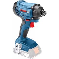
Due to its slow anti-clockwise rotation, the power tool is intended for operation with an open flat drive. It is suitable for working on screw connections that are only accessible from one side, e.g. on pipelines.
It is not suitable for loosening screws.
The power tool is not intended for drilling; in order to prevent personal injury and damage to property, power tools with a shut-off clutch should never be used for drilling.
Product Features
The numbering of the product features refers to the diagram of the power tool on the graphics page.
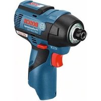
(1) Application tool (e.g. nut driver bit)
(2) Tool holder
(3) Angled screw head
(4) Open-ended spanner with width across flats of 27 mm
(5) Spanner flat on angled head flange
(6) Open-ended spanner with width across flats of 22 mm
(7) Slider for preselecting the torque
(8) Hanging hook
(9) LED indicator for screwdriving applications
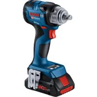
(10) Battery charge LED indicator
(11) Battery with contact APT
(12) Battery release button
(13) On/off switch
(14) Rotational direction switch
(15) Attachment slots for hanging hook
(16) LED holder
(17) Marking ring
(18) Worklight
(19) Spanner flat on the cap nut
(20) Lock nut
(21) Charger
(22) Mains plug
(23) Green LED indicator on the charger
(24) Red LED indicator on the charger
(25) Connection socket for a voltage adapter on the 4EX- ACT
(26) D-Sub connector plug
(27) Screws on the D-Sub connector plug
(28) Voltage adapter
(29) Quick-change chuck
(30) Adjustment tool
(31) Hex key
(32) Setting disc
(33) Spring ring
(34) Cavity in the housing shell
(35) Handle (insulated gripping surface)
Accessories shown or described are not included with the product as standard. You can find the complete selection of accessories in our accessories range.
Technical data
| ANGLE EXACT industrial cordless angle wrench 2 3 6 | ||||
| Article number | 0 602 490 647 | 0 602 490 656 | 0 602 490 652 | |
| Max. torque, hard/soft screwdriving application accord- ing to ISO 5393 | Nm | 2/2 3/3 6/6 | ||
| No-load speed n0 | min-1 | 110 420 650 | ||
| Rated voltage V 9.6 9.6 9.6 | ||||
| Direction of rotation | ΩΩ | ΩΩ | ||
| Weight according to EPTA-Procedure 01:2014 kg 1.0 1.0 1.0 | ||||
| Protection rating IP 20 IP 20 IP 20 | ||||
20 | English
ANGLE EXACT industrial cordless angle wrench 7 8 15
| Article number | 0 602 490 669 0 602 490 651 0 602 490 650 | ||
| Max. torque, hard/soft screwdriving application accord- ing to ISO 5393 | Nm 7/7 9/9 15/15 | ||
| No-load speed n0 | min-1 | 110 420 250 | |
| Rated voltage V 9.6 9.6 9.6 | |||
| Direction of rotation | ΩΩ | ΩΩ | |
| Weight according to EPTA-Procedure 01:2014 kg 1.0 1.0 1.0 | |||
| Protection rating IP 20 IP 20 IP 20 | |||
ANGLE EXACT industrial cordless angle wrench 17 23 30
| Article number | 0 602 490 675 0 602 490 673 0 602 490 671 | ||
| Max. torque, hard/soft screwdriving application according to ISO 5393 | Nm 17/13 23/20 30/28 | ||
| No-load speed n0 | min-1 | 560 320 220 | |
| Rated voltage V 14.4 14.4 14.4 | |||
| Direction of rotation | ΩΩ | ΩΩ | |
| Weight according to EPTA-Procedure 01:2014 kg 1.5 1.5 1.5 | |||
| Protection rating IP 20 IP 20 IP 20 | |||
ANGLE EXACT industrial cordless angle wrench 14CF 22CF 29CF
| Article number | 0 602 490 690 0 602 490 693 0 602 490 691 | ||
| Max. torque for hard screwdriving applications in clockwise rotationA) | Nm 10 16 20 | ||
| No-load speed n0in clockwise rotationA) | min-1 | 340 440 300 | |
| Rated voltage V 9.6 14.4 14.4 | |||
| Direction of rotation | ΩΩ | ΩΩ | |
| Weight according to EPTA-Procedure 01:2014 kg 1.0 1.5 1.5 | |||
| Protection rating IP 20 IP 20 IP 20 | |||
A) The power tools are slower in anti-clockwise rotation and have a lower torque. The speed and torque on the application tool change in line with the flat drive's transmission ratio.
| NiCd battery pack | 9.6 | 9.6 | 12.0 | 12.0 | 14.4 | 14.4 | |
| Article number | 2 607 335877 | 2 607 335659 | 2 607 335879 | 2 607 335375 | 2 607 335881 | 2 607 335655 | |
| Number of cells | 8 | 8 | 10 | 10 | 12 | 12 | |
| Battery voltage | V | 9.6 | 9.6 | 12.0 | 12.0 | 14.4 | 14.4 |
| Capacity | Ah | 1.8 | 2.4 | 1.8 | 2.4 | 1.8 | 2.4 |
| Weight according to EPTA-Procedure 01:2014 | kg | 0.45 | 0.50 | 0.65 | 0.70 | 0.70 | 0.80 |
| Recommended chargers | AL 2450 DV | AL 2450 DV | AL 2450 DV | AL 2450 DV | AL 2450 DV | AL 2450 DV | |
NIMH battery pack 9.6 12.0 14.4
| Article number | 2 607 335 681 | 2 607 335 683 | 2 607 335 685 |
| Number of cells | 8 | 10 | 12 |
| Battery voltage | V 9.6 | 12.0 | 14.4 |
| Capacity | Ah | 2.6 | 2.6 |
| Weight according to EPTA-Procedure 01:2014 kg 0.55 0.70 0.80 | |||
| Recommended chargers | AL 2450 DV | AL 2450 DV | AL 2450 DV |
English | 21
| Angled screw head | ■1/4" | ■3/8" | ■3/8" | ●1/4" | QC●1/4" |
| Article number | 0 607 453 617 | 0 607 453 620 | 0 607 451 618 | 0 607 453 618 | 0 607 453 630 |
| Maximum torque, hard screw- driving application according to ISO 5393 | Nm 20 25 30 20 20 | ||||
| Weight according to EPTA-Pro-cedure 01:2014 | kg 0.23 0.23 0.27 0.23 0.23 |
| Straight screw head QC 1/4" | ||
| Article number | 0 607 453 631 | |
| Maximum torque, hard screwdriving application according to ISO 5393 | Nm | 6 |
| Weight according to EPTA-Procedure 01:2014 kg 0.22 | ||
Noise/Vibration Information
Noise emission values determined according to EN 62841-2-2.
Typically, the A-weighted sound pressure level of the power tool is 70 dB(A). Uncertainty K = 3 dB. The noise level when working can exceed 80 dB(A).
Wear hearing protection
Total vibration values a_h (triax vector sum) and uncertainty K determined according to EN 62841-2-2: Screwdriving: a_h < 2.5 m/s^2, K = 1.5 m/s^2 .
The vibration level and noise emission value given in these instructions have been measured in accordance with a standardised measuring procedure and may be used to compare power tools. They may also be used for a preliminary estimation of vibration and noise emissions.
The stated vibration level and noise emission value represent the main applications of the power tool. However, if the power tool is used for other applications, with different application tools or is poorly maintained, the vibration level and noise emission value may differ. This may significantly increase the vibration and noise emissions over the total working period.
To estimate vibration and noise emissions accurately, the times when the tool is switched off or when it is running but not actually being used should also be taken into account. This may significantly reduce vibration and noise emissions over the total working period.
Implement additional safety measures to protect the operator from the effects of vibration, such as servicing the power tool and application tools, keeping their hands warm, and organising workflows correctly.
Assembly
Items included
ANGLE EXACT 2|3|6|7|8|15|17|23|30
These industrial cordless angle wrenches are supplied without application tools, angled screw head, straight screw head, battery pack, charger, constant voltage regulator or voltage adapter.
The voltage adapters are to be used exclusively to connect Bosch industrial cordless angle wrenches to the 4EXACT constant voltage regulator.
ANGLE EXACT 14CF | 22CF | 29CF
These industrial cordless angle wrenches are supplied without application tools, flat drive, intermediate flange, battery pack, charger, constant voltage regulator or voltage adaptor.
The voltage adapters are to be used exclusively to connect Bosch industrial cordless angle wrenches to the 4EXACT constant voltage regulator.
Operating and storage conditions

The power tool is suitable only for operation at enclosed work sites.
To ensure smooth operation, the permitted ambient temperature should be between -5^ and +50^ (23^ and 122^) , at a permitted relative humidity of between 20% and 95% , free of condensation.
The battery should be stored at a temperature of between 0 ^ C (32 F) and 45^ C (113 F) in order to avoid damaging the battery cells.
Fitting the angled screw head
ANGLE EXACT 2|3|6|7|8|15|17|23|30
These cordless angle wrenches must be fitted with a compatible angled screw head (see "Technical data", page 19) first.
Make sure that the rotational direction switch is in the middle position (lock-off function) or that the battery has been removed from the power tool before you fit, adjust or remove a screw head.
Hold the power tool with the open-ended spanner (6) against the spanner flat (5) of the angled head flange.
Never clamp the power tool to the housing shells.
Place the angled screw head (3) in the required position on the flange and tighten the cap nut with the open-ended spanner (4) against the spanner flat (19).
While doing this, place the open-ended spanner (6) against the angled head flange to hold it in place.
22 | English
ANGLE EXACT 14CF | 22CF | 29CF
These cordless angle wrenches must be fitted with a compatible flat drive first. There are different flat drives available on the market.
Ask your dealer for the appropriate flat drive.
Observe the fitting instructions for the flat drive.
Suspension device
You can use the hanging hook (8) to attach the power tool to a suspension device.
Fit the hanging hook (8) onto the power tool and make sure it engages in the slots (15).
Regularly check the condition of the hanging hook and the catch in the suspension device.
Charging process
Note: Batteries and chargers not included.
The mains plug pictured here may differ from that on your power tool.
Make sure that the charger and battery are suitable for your country's mains voltage.
Charger AL 2450 DV (see figure A)
Connect the charger (21) to the power supply with the mains plug (22) and insert the battery (11) correctly into the charging slot on the charger.
Do not use force to insert/remove the battery. Batteries with APT contact (Akku Pack Top, English: battery pack top) are designed such that they can only be inserted into the power tool or charger in the correct position.
The green LED indicator (23) will start to flash. This indicates that charging current is flowing. The charging process will stop automatically once the battery is fully charged.
When the charging process is complete, the green LED indicator will stop flashing and will be continuously lit. An sound is emitted for approximately two seconds, indicating that the battery is fully charged.
If the red LED indicator (24) is continuously lit, this indicates that charging is being carried out with a reduced charging current. If the red LED indicator is flashing, charging is not possible.
Errors - causes and corrective measures
Cause Corrective measures
LED indicators do not light up
| Mains plug of the charger is not (correctly) plugged in | Insert the mains plug (fully) into the plug socket |
| Plug socket, mains cable or charger defective | Check the mains voltage, have the charger checked if necessary by an authorised after-sales service centre for Bosch power tools |
Charging not possible
Battery temperature outside the permitted range
Lower or raise the battery temperature until it is in the permitted temperature range
of 0^ (32°F) to 45°C (113°F)
Cause Corrective measures
| Battery contacts are dirty Clean the battery contacts; e.g. by connecting and dis- connecting the battery sever- eral times. Replace battery if necessary |
Battery defective Replace the battery
Battery is not inserted (correctly) Insert the battery (fully) into the battery charging slot
Constant voltage regulator (see figure B)
ANGLE EXACT 2|3|6|7|8|14CF|15|17|22CF|23|29CF|30
Note: As an alternative to battery operation, industrial cordless angle wrenches can also be operated with a constant voltage regulator.
The mains plug pictured here may differ from that on your power tool.
Make sure that the constant voltage regulator is suitable for your country's mains voltage.
In addition to the 4EXACT constant voltage regulator and compatible mains cable, you will also need a voltage adapter with the same rated voltage as your screwdriver.
The voltage on the constant voltage regulator (LED indicator) must match the voltage of the screwdriver.
The constant voltage regulator is only suitable for Bosch industrial cordless screwdrivers from the EXACT, ANGLE EXACT and BT-EXACT series with a voltage of between 9.6 V and 14.4 V. Otherwise there is a risk of fire and explosion.
Connecting to the power supply
Note: On delivery, neither a battery nor a voltage adapter are inserted in the power tool.
Never store batteries inside a battery-powered tool.
Batteries will remain functional for longer and can be charged more easily if they are stored separately. Please remember to fully charge the battery prior to use after longer periods of storage.
Battery Charging
Charge the battery using a suitable charger before inserting it in the power tool. The charging process is described in detail in the charger's operating manual and the instructions of this manual (see (see "Charging process", page 22)).
The battery features NTC temperature monitoring, which only permits charging in a temperature range between 0^ (+32^) and 45^ (+113^) . This achieves a long battery life. If used correctly, the battery can withstand up to 3000 charging cycles.
A new battery or one that has not been used for a long time will only operate at full capacity after approximately five charge and discharge cycles. Batteries should only be
charged if the battery charge LED indicator on the power tool lights up red.
Inserting and Removing the Battery
Push the rotational direction switch (14) into the middle position. This locks the on/off switch (13) in the "Off" position and prevents the power tool from being switched on unintentionally.
Push a charged battery (11) into the handle of the power tool.
Make sure that you insert the battery correctly and that you can feel the release buttons (12) engage in the handle of the power tool.
Do not use force to insert/remove the battery. Batteries with APT contact (Akku Pack Top, English: battery pack top) are designed such that they can only be inserted into the power tool or charger in the correct position.
To remove the battery (11), press the release buttons (12) on both sides and pull the battery down and out of the handle.
Inserting and removing the voltage adapter (see figure C)
ANGLE EXACT 2|3|6|7|8|14CF|15|17|
22CF|23|29CF|30
Select the voltage adapter that matches your power tool's rated voltage.
The voltage adapters can be differentiated by the colour of the housing of the D-Sub connector plug (26), which differs according to voltage. The housing of the D-Sub connector plug for a voltage of 9.6V is light blue, the one for a voltage of 14.4V is black.
The adapter housing (28) may only be fitted on or removed from the industrial cordless screwdriver when the constant voltage regulator is switched off or when the connector plug (26) is disconnected from the constant voltage regulator.
Push the rotational direction switch (14) into the middle position. This locks the on/off switch (13) in the "Off" position and prevents the power tool from being switched on unintentionally.
Then push the adapter housing (28) into the handle of the power tool. Make sure that you insert the adapter housing correctly and that you can feel the release buttons (12) engage in the handle of the power tool.
Then insert the connector plug (26) for the voltage adapter that is compatible with your power tool into the connection socket (25). Tighten the connector plug (26) in the connection socket (25) by hand-tightening the two screws (27).
To remove the voltage adapter, loosen the two screws (27) on the connector plug (26) of the constant voltage regulator (switched off) and remove the connector plug from the connection socket (25).
Then press the release buttons (12) on both sides and pull the adapter housing (28) out of the handle of the power tool.
Changing the tool - screw head with quick-change chuck (see figure D)
- When fitting an application tool, make sure that it is held securely in the tool holder. If the application tool is not held securely in the tool holder, it may become loose and consequently uncontrollable.
ANGLE EXACT 2 |3|6
An angled screw head with a 1/4 quick-change chuck is available for these industrial cordless angle wrenches (article number 0607453631).
ANGLE EXACT 2 | 3 | 6 | 7 | 8 | 15
An angled screw head with a 1/4 quick-change chuck is available for these industrial cordless angle wrenches (article number 0607453630).
Inserting the application tool
Pull the quick-change chuck (29) forwards. Insert the application tool (1) into the tool holder (2) and release the quick-change chuck again.
Only use application tools with a matching shank (1/4" hexagon).
Do not attempt to insert drill bits into this quick-change chuck.
Industrial cordless angle wrenches with a shut-off clutch are not suitable for drilling. The clutch can shut off automatically and without warning. If you continue drilling after the clutch has shut off, the power tool may be wrenched out of your grip until the shut-off clutch engages again.
Removing the application tool
Pull the quick-change chuck (29) forwards. Take the application tool (1) out of the tool holder (2) and release the quick-change chuck again.
Changing the tool - screw head with external square
- When fitting an application tool, make sure that it is held securely in the tool holder. If the application tool is not held securely in the tool holder, it may become loose and consequently uncontrollable.
ANGLE EXACT 2 | 3 | 6 | 7 | 8 | 15
An angled screw head with a 1/4" square (article number 0607453617) and an angled screw head with a 3/8" square (article number 0607453620) are available for these industrial cordless angle wrenches.
ANGLE EXACT 17|23|30
An angled screw head with a 3 / 8" square is available for these industrial cordless angle wrenches (article number 0607 451 618).
Inserting the application tool
Press the pin on the square of the tool holder (2) inwards, e.g. using a narrow screwdriver, and slide the application tool (1) over the square. Ensure that the pin engages in the recess of the application tool.
24 | English
Removing the application tool
Press the pin in the recess of the application tool (1) inwards and pull the application tool off the tool holder (2).
Changing the tool - screw head with hexagon socket (see figure E)
- When fitting an application tool, make sure that it is held securely in the tool holder. If the application tool is not held securely in the tool holder, it may become loose and consequently uncontrollable.
ANGLE EXACT 2|3|6|7|8|15
An angled screw head with a 1/4" hexagon socket is available for these industrial cordless angle wrenches (article number 0607 453 618).
Inserting the application tool
Push the application tool (1) into the internal hexagon of the tool holder (2) until you hear it engage.
Removing the application tool
Pull the application tool (1) off the tool holder (2), using pliers if necessary.
Operation

Use personal protective equipment. Always wear eye protection. Protective equipment such as a dust mask, non-skid safety shoes, hard hat or hearing protection used for appropriate conditions will reduce personal injuries.
Starting Operation
Always set the rotational direction using the rotational direction switch (14) before starting the power tool: The power tool will not start if the rotational direction switch (14) is in the centre (lock-off button).
Setting the rotational direction (see figure F)
Only push the rotational direction switch (14) when the power tool is not in use.
Clockwise: To drive in screws, press the rotational direction switch (14) all the way to the left.
Anti-clockwise: To loosen or unscrew screws, press the rotational direction switch (14) all the way to the right.
Switching on the worklight
The worklight (18) illuminates the work area in poor lighting conditions. Switch on the worklight (18) by lightly pressing the on/off switch (13). If you press down harder on the on/ off switch, the power tool will switch on and the worklight will remain illuminated.
Do not look directly into the worklight; it can blind you.
Switching on/off
The screwdrivers have a torque-dependent shut-off clutch that can be set to a value in the specified range. It activates when the set torque is reached.
Note: If you are operating the screwdriver with a voltage adapter, you will need to put the constant voltage regulator into operation first.
To switch on the power tool, press the on/off switch (13) down fully.
The power tool will switch off automatically when the set torque is reached.
If the on/off switch (13) is released too early, the preset torque will not be reached.
Practical advice
- Remove the battery from the power tool before carrying out work on the power tool (e.g. maintenance, changing tool, etc.). The battery should also be removed for transport and storage. There is risk of injury from unintentionally pressing the on/off switch.
Only apply the power tool to the screw/nut when the tool is switched off. Rotating tool inserts can slip off.
Setting the torque (see figures G - I)
The torque depends on the spring preload of the shut-off clutch. The shut-off clutch is triggered upon reaching the set torque, both in clockwise and anti-clockwise rotation. Only use the supplied adjustment tool (30) to set the individual torque.
Slide the slider (7) on the power tool back completely.
ANGLE EXACT 2|3|6|7|8|15|17|23|30
Insert a hex key (31) into the application tool (30) and turn it slowly.
Once a small protrusion (setting disc (32)) in the clutch can be seen through the opening of the housing, insert the adjustment tool (30) into this protrusion and turn it.
ANGLE EXACT 14CF | 22CF | 29CF
Observe the information for your purchased flat drive or ask your dealer.
Turning clockwise will result in a higher torque; turning anticlockwise will result in a lower torque.
Remove the adjustment tool (30). Slide the slider (7) to the front again to protect the clutch from contamination.
Note: The required setting is dependent on the type of threaded connector and can be best determined by practical trials. Check a trial screw application with a torque spanner.
If you set the torque to a value outside the specified power range, the shut-off clutch will not be triggered.
Marking the torque setting
ANGLE EXACT 2|3|6|7|8|14CF|15|17|22CF|23|29CF|30
To label individually set torques, you can replace the marking ring (17) with a marking ring of a different colour.
If you use certain EXACT power tools with a torque of 4.5 Nm, for example, you can fit red marking rings on these to identify the set torque. If you use other EXACT power tools in a different assembly area with a torque set to 7.5 Nm, you can fit a marking ring of a different colour (black, blue, green or yellow) to identify the torque in this area. The different marking ring colours are only intended as an aid for fitters to
facilitate identifying the set torque on a specific power tool. Press the marking ring (17) with a thin screwdriver blade, a spatula or similar implement.
Always use the power tool with a marking ring to be certain that the housing is protected against dust and dirt.
LED indicator

Battery charge indicator
If the battery (11) needs to be charged, the LED indicator (10) flashes green and a sound is emitted. You can only drive in six to eight
more screws.
If the LED indicator lights up red, there is not enough capacity left to drive in another screw or the power tool has overloaded. The power tool can no longer be switched on. The lock-off function remains active until the drained battery has been removed from the power tool and a charged battery inserted.
If you are working with a voltage adapter, the red LED (10) indicates overloading.
If the LED indicator (10) flashes red, the power tool has overheated and switched itself off. Wait a short while for the light to stop flashing before switching the power tool on again.
A significantly reduced operating time of the power tool after charging indicates that the battery must be replaced soon. Dispose of depleted batteries in accordance with legal/country-specific provisions.

Indicator for screwdriving applications
The shut-off clutch is triggered upon reaching the preset torque. The LED indicator (9) lights up green.
If the preset torque has not been reached, the LED indicator (9) lights up red and the tool emits a sound. The screw must be driven in again.
Repeat protection
If the shut-off clutch is triggered while driving a screw, the motor will switch off. You will need to wait 0.7 seconds before you can switch the tool on again. This prevents you from accidentally retightening screws that are already firmly in place.
Adjusting the angled screw head
ANGLE EXACT 2|3|6|7|8|15|17|23|30
You can adjust the angled screw head (3) to a total of eight different positions.
Hold the power tool with the open-ended spanner (6) against the spanner flat (5) of the angled head flange.
Never clamp the power tool to the housing shells.
Loosen the cap nut with the open-ended spanner (4) against the spanner flat (19). Move the angled screw head (3) in 45^ degree increments into the required position and tighten the cap nut again with the open-ended spanner (4) against the spanner flat (19).
While doing this, place the open-ended spanner (6) against the angled head flange to hold it in place.
ANGLE EXACT 14CF | 22CF | 29CF
Observe the information for your purchased flat drive or ask your dealer.
Adjusting the LED worklight (see figure J)
ANGLE EXACT 2|3|6|7|8|14CF|15|17|22CF|23|29CF|30
Press the marking ring (17) with a thin screwdriver blade, a spatula or similar implement. Slide the spring ring (33) back onto the housing shell using a pair of spring ring pliers.
The two shell halves of the LED holder (16) that encase the LED worklight (18) can now be brought into the required position. Taking care not to damage the cable on the LED worklight, slide the cable into the cavity provided for it (34) in the housing shell without allowing it to bend. Encase the LED worklight (18) in the two housing shells of the LED holder (16) once again.
Press the spring ring (33) and the marking ring (17) back into their original position.
Maintenance and Service
Maintenance and Cleaning
- Remove the battery from the power tool before carrying out work on the power tool (e.g. maintenance, changing tool, etc.). The battery should also be removed for transport and storage. There is risk of injury from unintentionally pressing the on/off switch.
To ensure safe and efficient operation, always keep the power tool and the ventilation slots clean.
Lubricating the power tool
Lubricant:
Special gearbox grease (225 ml)
Article number 3605430009
Molykote grease
Motor oil SAE 10/SAE 20
- Clean the gearbox with a mild solvent after the first 150 operating hours. Follow the solvent manufacturer's instructions on use and disposal. Then lubricate the gearbox with Bosch special gearbox grease. Repeat the cleaning process once every 300 operating hours after cleaning has been carried out for the first time.
- After driving 100,000 screws, oil the moving parts of the shut-off clutch with a couple of drops of SAE 10/SAE 20 motor oil. Lubricate the sliding and rolling parts with Molykote grease. Use this occasion to check the clutch for wear to ensure that accuracy and reproducibility have not been affected. You will need to reset the clutch torque once you have done this.
Have maintenance and repair work performed exclusively by a qualified specialist. This will ensure that the safety of the power tool is maintained.
An authorised Bosch after-sales service point will handle this work quickly and reliably.
26 | English
- Dispose of lubricants and cleaning products in an environmentally friendly manner, taking legal regulations into account.
After-Sales Service and Application Service
Our after-sales service responds to your questions concerning maintenance and repair of your product as well as spare parts. You can find explosion drawings and information on spare parts at: www.bosch-pt.com
The Bosch product use advice team will be happy to help you with any questions about our products and their accessories.
In all correspondence and spare parts orders, please always include the 10-digit article number given on the nameplate of the product.
Great Britain
Robert Bosch Ltd. (B.S.C.)
P.O.Box 98
Broadwater Park
North Orbital Road
Denham Uxbridge
UB95HJ
At www.bosch-pt.co.uk you can order spare parts or arrange the collection of a product in need of servicing or repair.
Tel. Service: (0344) 7360109
E-Mail: boschservicecentre@b Bosch.com
Ireland
Origo Ltd.
Unit 23 Magna Drive
Magna Business Park
City West
Dublin 24
Tel. Service: (01) 4666700
Fax: (01) 4666888
Australia, New Zealand and Pacific Islands
Robert Bosch Australia Pty. Ltd.
Power Tools
Locked Bag 66
Clayton South VIC 3169
Customer Contact Center
Inside Australia:
Phone: (01300) 307044
Fax: (01300) 307045
Inside New Zealand:
Phone: (0800) 543353
Fax: (0800) 428570
Outside AU and NZ:
Phone: +61 3 95415555
www.bosch-pt.com.au
www.bosch-pt.co.nz
Republic of South Africa
Customer service
Hotline: (011) 6519600
Gauteng - BSC Service Centre
35 Roper Street, New Centre
Johannesburg
Tel.: (011) 4939375
Fax: (011) 4930126
E-mail: bsctools@icon.co.za
KZN - BSC Service Centre
Unit E, Almar Centre
143 Crompton Street
Pinetown
Tel.: (031) 7012120
Fax: (031) 7012446
E-mail: bsc.dur@za.bosch.com
Western Cape - BSC Service Centre
Democracy Way, Prosperity Park
Milnerton
Tel.: (021) 5512577
Fax: (021) 5513223
E-mail: bsc@zsd.co.za
Bosch Headquarters
Midrand, Gauteng
Tel.: (011) 6519600
Fax: (011) 6519880
E-mail: rbsa-hq.pts@za.bosch.com
Disposal

The machine, rechargeable batteries, accessories and packaging should be sorted for environmental-friendly recycling.
Do not dispose of power tools and batteries/ rechargeable batteries into household waste!
Only for EU countries:
According to the Directive 2012/19/EU, power tools that are no longer usable, and according to the Directive 2006/66/EC, defective or used battery packs/batteries, must be collected separately and disposed of in an environmentally correct manner.
Battery packs/batteries:
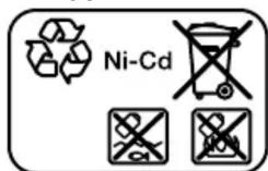
Ni-Cd: Nickel cadmium
Warning: These battery packs contain cadmium, a highly toxic heavy metal.
Ni-MH: Nickel metal hydride
François
Protection antiredemarrage
Robert Bosch (France) S.A.S.
Calle Robert Bosch No. 405
C.P. 50071 Zona Industrial, Toluca - Estado de Mexico
Tel.: (52) 55 528430-62
Tel.: 800 6271286
Ni-Cd: nickel-cadmio
Bosch Service Center
Telegrafvej 3
2750 Ballerup
På www.bosch-pt.dk kan der online bestilles reservedele el-ler oprettes en reparations ordre.
TIf. Service Center: 44898855
Fax: 44898755
E-Mail: vaerktoej@dk.bosch.com
Bortskaffelse

Ni-Cd: Nikkel-cadmium
Bosch Service Center
Telegrafvej 3
2750 Ballerup
Danmark
Tel.: (08) 7501820 (inom Sverige)
Fax: (011) 187691
Avfallshantering

akoum ot ngon ON, toe denuoyeiit kivuvoc tpaumiaow.
Anopakpuve ano to nlektpiko epyaleio tuxov aaptnmuata puhuonc kleidiia npiv theoetto nlektpiko epyaleio oe letioupyia. 'Eva epyaleio n kleiidi ouvapmooynevo o' eva nepiotppeofovo tueta evoc nlektpiko ou epyaleiou mopei va oynoei oetpaumatououc.
PpooexTe nwc stekoeTe.ΦpvriTe yia tyn aopaln otaoiou owpatoc oac kal diatnpite navtoTE tv Ioopponia oac. Etai npopeite va eleyeTe kaluTepa to nlektipok epyaieio oe nepiittwoei c anpoobokntwv nepiotadewv.
Φopate oωπη ενδμασia. Mn φopate φapδιa pouxa n koμημata. Kpatate ta μaλλa kal ta pouxa oa kakpiä ano ta kivouμεva εξaptημata. Xaapn evδuασia, koμημata n μakpiα μaλλa μnopei va εμλakouv στa kivouμεva εξaptημata.
Otav unapxiei n duvatotnta ouvdeocn diataeewy avappopnonc noulloync o Kovnc,betaawtheta ot autec eival ouvdebcevec kai otxnpounoiouvt a owoTa. H xpan mucavappopnonc oovnc mpoei va elattwoei tov kivduvo nou npokaletiat ano tn ocovn.
Mny eponauzTe oia laooc aopaleia kai mny aynpatoukavoeacaaipiaicyta nlektipka epyalaea,akoa kai otav meta ano ouxv hphon iotc eoikewevoltepyaleio.Evac anpooektoc xieipaoocmuopei meoae kaaoataou deutepoletiou o oynoei oobapouc trpaumatouc.
Xpion kai povrtda twv nAektpkow epyaleiw
Mnu unepoortwve to nektpko epyaleio. Xpnaouonoiote to oawto nektpko epyaleio yia tny eapouynac. Me to katalno nlektpko epyaleio epyaceote kalutepa kai aqphaeotepa otyn avapepevny nepioxnoxuoc.
Mn xnpouonouoote note eva Nktpko epyaleio tou exeiaaauve diaokntn On/Off. 'Eva nkeptko epyaleio nou dev mopoeite nleov va to oeoetoe λeitoupyia kai/n ektoc aeitoupyiac elvai enikivduvo kai npenei va eniokueaosteie.
AnouvdeTo oic ano TnV npica kal/ anopakpuveTe mia anoonwmevnmuatapia ano to nAeKtpko epyaaleio, npotou ekTeAoeTe puOmuieC, aAalaEeTe EApntjmuata n npotou quAaEteTo nAeKtpko epyaaleio.Aut Ta npoAanTikia metpa aaopeiaic meiwovu tov kivduvo ano tuXov aheAent ekkivnoi tou nAeKtpko epyaaleiou.
Duayete Ta nlektipka epyaleia nou de xpnouoiouvtai jakpi a no naidi kai mny eniippeyote Tn xpnoi Tou nlektipko epyaleiou o atoua tou dev elvai eoikwepva te nlektipco epyaleio niocnyiec yia Tn leitoupyia tou nlektipko epyaleiou. Ta nlektipka epyaleia elvai etikivduva otav xnpouoiouvtai aneipa npoomega
SuvtnpieTa nIeKtpiKa epyAei Ka ta EApntma. ELexyTe, av Ta Kivoumuva EApntmuata eiva oWot a Euoypaumupeva kai npoapnpoumeva n mwnoc exouv
oanae tuxov eapntjma t onoiadhnotae aan kataota, n onoa enpezie tn letoupyia tou nkeptko epyaleiou. Se nepintwn c, etokueaoote to nkeptko epyaleio npv tn xon. H kakn ouvtnoan twnv nektpikw evyaaleiw anoteai atia noaaa v atuxmuw.
DiatnpieTe ta epyaia konnc KoPtepa kai kathetapa. Ipooektikauvtnpneva konttka epyaia opnvovuv duokolotepa kai odnyouvtai eukolotepa.
Xpnooie ta nekpiKa epyaia ta eapntmuata kTAL. uupwva me autc tic onyic, lajavovtac unoyn TIC auvOnke c npaiaoc kai t c npaoc nou npenti va ekteaouiv. Hxnpooinan twv nekpiKw evayaleiwvi eyaaiec nou dev npoletovta yi' auta mnpoei va oniuoynei enikivuvcnc kataotaeic.
Aiatnpceite Tc a c Kai Tc enipaveieC a n OTeyve, kaapc kai eueoepacno lai kalpao. O1 oiaopc a c kai enipaveieC a n 6ev entptioukavevav aopaln xeiipioKai eleyxTou nlektipouepyaleiou oe tuxov anpoBaeTc kataotadoeic.
Tpoektikoc xeiipiaoc kalxipion epyaaleiw npatapiac
Enavaopoptiete movo me tov foptiotn nou kaobopicetau ano tov kataaekuaot. 'Evac optiotnc nou eivai kataaanloc mvo yia eva auykepiévo tuno mnatapiwv denioupyei kivduvo npkayiac otav xpaonointhetai yia alec mntapiec.
Xpnooie ta nektpika epyaleia movo pe tic 16ikka oxdeltaevc mpatipec. Hxnpn alwwmuataiw mopoie va oynnoe o tpaumioouc kai va oyniounyoei kivduvo npkayiac.
OTAV n unatapia de xpooutoieitai, kpatnoTe TnV paKpia ano aAAA petaAUAkavtkeiEvA,OnWC ouvdeTneC XaPTWv,voiogata, KLEdiA, KAPPIA, BiEc n aAAmuKa pTaAUAkavtkeiEvA nou mnpovvaBpauxukkawuVTc enapec TNC mnatapiac. 'Eva BpauxukkawmaTwv eanpwTVNCS mntatapiac mnpoei va npokaoleeipaumuioouc n foTia.
Mia tuxov copaalpevn opon mnpoei va odnynoei oe diappoyn uypow ano tnv mnpatia. Anopoeuyete kaohc enapn ma'auta. Se nepinwn tu xuaiae enapnc Eenluve ta kala e vepo. Eav ta uypa epouov oe enapn me ta maia, zntneote emnleov atpkih bohceia. Diappoevtva npaunatapiacmnpoei va odnynooue epeioouc tou depaotc n oe ykaumata.
Mnyxnpouoitemuatapia n epyaieo nou civa kateopaupevo n troponoounevo. Oxaagvec n troponoouneve, mntapiec, mnoei va napouiaouv ma a npoblaenounpopa kai va oynuouv o wti, ekpnEn oke kivduvo tpaumiaou.
Mny ekOeTeE mua unatapia n eva epyaleio unatapiac oE pwtia n e nou uynl cepkopaiec. Hekoeon otn pfwiad n e 0epuokpaoia navw ano touc 130°C mnpoei va npokaeei ekpnIg.
TnpieTe oLeC tuc unoBeiEic yia tn pOpiTn kal n npopriTe Tnu matarapia n to epyaaleo matarapiac nore EKTOCTNc nepioxnc 0epuokpaoia cou avapeptai otic
obnyie c leitoupyiac. H aOc ofoption n nofoption ektoctn eIITpemtnncpeioxnc theoekpaiaac mnopei va kataotpepsi tnv mpatia kai va auEhoi tov kivduvo npkayiac.
ερβις
to nlektropo epyaleio ac yia ouvtnpon ano eEiikkeupevo npoosniok, xnoaopoowvntac movo vvioaavtaalaktka. Eoi eaoaipizetn diatnpon Tnc aopaaieiac tou nlektropko epyaleiou.
Mn ouvtneite note xaalaevc unatapiec. KaOeoutnpnoan twv mntapiw npenei va npayatonoietraovo ano tov kataokueaotn ano eouioobotmeva ouveyia oepic nelaowv.
YnObeiEic aocpaLeia c yia katoaibia
Kpatate to nlektipko epyaieio ano tic movwveec enipaveiec laibc,otav ekteleitemu epyaia, kata tv onoi na bia umoei va ethetae enapn pe Kpuuvmakawioh. H enapn tnc ibac me eva nlektropopo kaawdoio umoei va thee ta akalunta metaalika depn tou nlektipkoepyaeiou uno raon kalva npokalaosuv nlektponlaia otov xeiipotn.
Xpouponoiie KatalanLc ouakeueavxveuaqyia vaevtonoetuovmopatoucaywooctpopoobooiac noubouleutei Tnv toniketaipia npoxnc evepyeac.H enapn me nektpiokouc aywyouc mtopei va obnynoei ne npukayia kai nektponlanxi. H npoknan Znmuac o' evav aywoo wftaepiou (ykaio) mtopei va obnynoei oe ekpnEe. To prunma evoc ubpoosna vnpokale ulikec znuiec.
Kpatate to nlektipko epyaieio otaepa. Karat o 0piEIO kai luuio tuv biDow mnpovv va emuavioTuV yia liyo uynLc ponec avtdpaanc.
Aopaiot to eeneepyafoevo koumu. 'Eva eeneepyafoevo koumu tsiuykpatietai oaoaaleoepa me ia diataenouoipivncn ie mia neyve npapae to xepiaac.
Pepuevete, mexvi aakvntonountheta to nAektpiko epyaieio, npotou to evantoedote. To tonoetnevo eaptnma uopei va opnvwaekai voadnyoei otny anwaeia tou leyou tou nAektpkoE epyaieiou.
Σε πεπιτωπ βλαβης ἡ/και avικανονικής χροῦς τής μησταρίας μηορείνα εξέλθουν αναθυμίαεις ἀπό την μησταρίας μηορείνα αναφλεγείνα εκραγείνα Αρότενα μηε φρεδακός ἡράς και εἰπιακόμερτείνεν γιατόσε Επεπιτωπ Πιου ἐχετε εύχλησεις.Οι αναθυμίαεις μηορείνα ερεθίαουν τής αναννευσικός ὅδους.
Mny avoiyete nvy mnatapia. Ynapxekivouoc pauxukkawatoc.
An oixnpa avtkeiueva, onoc n. x. kappia n kataoibia n ano eXwepikn aeknon duvaumc mnopei va unootei zmuia n maataopia. Mnpei va poknthe eva eawteriko bpauxukkwa ma enotaleega tny avaplexn, tnv eupavian kaivou, n vekpnn n tvu npeppuan nnc mnatapiac.
Xpouoie Tnu npatia mvo o npovtou kataokuaotn. Movo etai npoataeetai n npatia ano ma enikivuvn utepoption.


Ipootateute TIV mataopia anu unepolukec
Oeipokpaiec, n. x. akoun kal ano ovexn
nlaikakntaktioia, pwtia, pumavan, vepo
kai uypasia.Ynpxei kivduoc ekpnnc kal
bpaxukkawatoc.
Anevpyoouote aoeoc to nAeKtpko eyaaleo,otav to EApntma pILOkapei. Na eioe npoetouauevo yua uynlccponec avtispaocn,oi onoiec npokalouv avdeltaon.ToEapntma pILOkapei,otav to nAeKtpko eyaieo unepoprtwoei naykwtheta eeneepyaOevo koumuati.
TIPPOEI0-TOIHsH
H 6nuioupyoueyn kara to Tpiuipo, npovua, Aeavoc, Tpueta kalnapoiec eypaoiec
okov mopei va eivai kapkvoyovc, tepatoyovc n metaaXoyovoc. Opiouevc ano tic ouoiec nou nepieoxovta oe autec tic okovc eivai:
Moluboc oe moulboduyxa xwmuata kai Bervikia, kpuotaaliko npitio oe touba, taevto kai aalec epyaiec toixoianiac, apoeviok kai xpomega kaac oe xnuika eneepyaemvo Eufo. O kivduoc iaac aoteveic agaptatai ano to noo ouxva eioTe ekteohnevo ie autec tic ouoiec. Tia va meiwotetov kivduvo, npenei va epyaceote movo oe kaalepcevouc xwpouc me kalalno eoonlaio npoaiaic, (n.x. me ioka kataakeuaagvec avanveuotikc oukeuec, o onoiec pfapouv akounkai ta ikpotepa miipooawatldia okovnc).
Anopeuyete mia atheaeneyepyonoan. Beauwote, oI O diaokntnC On/Off piokeTAt OTNv anevepyoouniev theonpoTuToOnoetnoe Mua natapia. H metapopacou nektpkoepyaoleiou me to daktuO tov diaokntn On/Off, n tonoetnon TNC matapiaocto epeyoounue no ktpkoepyaaleio, monei va onnyae o atuxneta.
XpouoieTe mO ov apoya, mPapve EApntmuTa. Xaaoeva EApntmuata mOpov yia npadoeiya va otaoov kai va odnyoouv oE Tpaumatioouc h/kai va npokaleouv ulikc znuiec.
PooeeTe kata nTv tonooetnnon evoc eapntmuatoc, va npoaappozetai to eaptnma oTaepa otnv unodoxn tou aaptjmuac.OTav to eaptnma dev evai oTaepa ouvdeedeveo me tvn unodoxn tou eapntmuac, mnpoei va lutheta iavava ka va mnue lyexetai ploev.
Kata to biδwμa kαριων βiδων va εοτe προεκτιοι, unapxei kivduoc oλισθησκ avλoγ με to eio6c TNC βiδac kal to xρησμοποιμενο εξαρημα.Σuxvá, kat to biδwμa, o iakpiες βidec dev μορούν va ελεχθουν κι εται unapxei kivduoc va γλιστρησουν kal vα σας τραματίσουν.
PoooeTe Tn puOmuOevn oopa nepoTpoopcn, npoTu evpyoonoiote To naektpko epyaieio. O'atv ia napadeiyma thete va luOeTe mia biida kai n oopa n peiotpoppc eivai puOmuEyn etai, wote va biDomegaei n Biida, mnpoei va pokupei ia anotoun, aveXeIeyktn Kivnan Tou nakeptko epyaieiou.
IIaepopoeic yia opuBo kal dovinoeic
Tuec ektnoumnc oporbou unoloyioeves kaT EN 62841-2-2.
kg0,450,500,650,700,700,80
01:2014 uyarinca
Tavsiye edilen Şarç cihazlari AL 2450 DV AL 2450 DV AL 2450 DV AL 2450 DV AL 2450 DV
Nikel metal hidrit akü paketi 9,6 12,0 14,4
| Malzeme numarası | 2 607 335 681 | 2 607 335 683 | 2 607 335 685 |
| Hücre sayiş 8 10 12 | |||
| Akü gerilimi V 9,6 12,0 14,4 | |||
| Kapasite Ah 2,6 2,6 2,6 | |||
| Ağırkı EPTA-Procedure 01:2014 uyarınca kg 0,55 0,70 0,80 | |||
| Tavsiye edilenmiş cihazları AL 2450 DV AL 2450 DV AL 2450 DV |
| Açili vidalamaCLS | 1/4" | 3/8" | 3/8" | 1/4" | SWF 1/4" |
| Malzeme numarası | 0 607 453 617 | 0 607 453 620 | 0 607 451 618 | 0 607 453 618 | 0 607 453 630 |
| ISO 5393'e güre sertvidalamada(Maximum tork) | Nm | 20 | 25 | 30 | 20 |
| Açirliigi EPTA-Procedure01:2014 uyarınca | kg | 0,23 | 0,23 | 0,27 | 0,23 |
| Düz vidualama bestehtği | SWF 1/4" | |
| Malzeme numarası | 0 607 453 631 | |
| ISO 5393'e güre sert vidualama(Maximum tork) | Nm | 6 |
| Ağırkı EPTA-Procedure 01:2014 uyarınca | kg | 0,22 |
Gürültü/Titreşim bilgisi
Robert Bosch Sp. z o.o.
Bosch Service Center PT
K Vapence 1621/16
692 01 Mikulov
PekomeHnyetcOuHCTnTbHHCTpyMeHT OT nbIIN NOcNe KaK-DOTO HcONb3OBaHN.
Xpahenne
- Heo6xOДIMO XpaHnTb BCyXOM MeCTe
- Heo6xOIMO xpaHnTb BdaIIN OT hCTOuHNKOB IOBblIeH-HbIX TEMpeaTpI BO3dEiCTBnA COJIHeuHbIX Lyuei
-Приханени Heo6xOДМо n36eRaTb pe3KOro nepenada TempepaTyp
-xpaHeHne 6e3 ynaKOBKn He dOnyckaTeCn - fnoDpO6HbIe Tpe6oBaHnK yCNoBnM XpaHeHnCmOTpuTe B FOCT 15150 (YcNoBne 1)
TpaHcnpToPbOvBa
- KaTeROpHueCKe HnOJyCKaETcnaIeHne NIIIObIe MExaHnUeCKe BO3dEiCTBnHa yNApKOBky npn TpaHCnOpTHpOBKe
-прп раэгузke/ногузke He дolyнскаетс И спольва-bne lioboro Bnda texhniK, paobotaошeй no приицуny 3aЖIMa ynaKOBKN - noIpo6HbIe Tpe6oBaHnK yCNoBnAM TpaHcnpTIpOBKn CMOTpnte B FOCT 15150 (YcNoBne 5)
Yka3aHnI IO TexHnke 6e3OnaCHOCTn
06uhe yka3aHnno ToxHnke 6e3oNaChocht dna 3JeKtpOnHcTpymEnTOB
IPENyPEXJEHNE
IpouHTaTe Bce yka3aHnno texHnke 6e3oNaChocn, nHcTpkyuHn, HnJIIOCTpaHn cneuΦHKaUHn,
IpeoocTabHeHbIe BMeCTe C HactOaHm 3NeKtpOnHcTpyMeHToM. HecobIoJeHne KaKx-Im60 n3 yka3aHHbIX HnKe INHCTpyKuIM MOKeT CTaTB pNCHNOI pOpAKeHnE 3NeKtpUeCKHM TOKOM, POnJa N/INN TReKebblx TpaBM.
CoxpaHaiTe 3TH HnCTpyKcHn HyKa3aHnI dIg 6dyuero HCIOb3OBAHH.
IcnoIb3OBAHHoe B HAcTOnuHx HNCTpyKunx H yKa3aHnX NOHrTHe 念 E k T P o n H C T p m e T M ) pacnpoctpaHreTcHa 3eKTPoHNCTpymeHT C NITaHnEM OT cTei (C cTeBbIM shyPOM) Ha aKKyMylTophbl 3eKTPoHNCTpyMeHT (6e3 ceTeBoro shHypa).
Бezopachoctb pa6oery Mecta
CoepKHe pa6ooye MeTo B uHCTOte H XopoIo ocBe-ueHHbIM. BecnopAIOk IIN HeOCBeUeHHbIe yuaCTKn pa6oeryo MecTa MOyT pInBecTu K HeCuaCTbIM CnuyaM.
He pa6oTaIe C3NeKtpOnHCTpymEnAmu BO B3pbIBOonacNoaMocpepe, HnAp., CoedeJxaue IropUcneXnIKoCTN,BOCpMaMeHnIOUncEra3bI NIN NbINb.3NeKtpOnHCTpymEnTbI NCKPrt, YTO MoKET pInBeCTN KBOCpMaMeHnIO NbIN NIN NapOB.
Bo Bpempa6oTbC3neKtpOnHcTpymeHtOM He donyckaiTe 6n3ko K Baewemy pa6ooyMe MeCTy TeTe H nocToPOHHnx NlU. OTBNeKUnsCb, Bbl MoKeTe NotepaTb KOHTpOlb HaD 3neKtpOnHcTpymeHtOM.
3neKtpo6e30nacHocTb
1Wtencelbna Bnka 3NeKtpOnHcTpymeHa D0JXHa noxOAnTb K WtencelbHoN po3eTke. Hn B Koem cny- yae He BHOCTe N3MeHeHHB WtencelbHyUo Bnky. He npImeHnIte nepExoHbIe WtKepebl dJe 3NeK TpOHcHpyMeHTOB C 3aUnTHbIM 3a3EmneHHem. Hen3MeHeHHbIe WtencelbHbIe BnIKn I NOxOJaIue WtencelbHbIe po3ETKN CHNXaHOT pNCK nopaXeHHa 3NeK- TPOTOKOM.
PpeoTbpaaTe TeleChbIK KOtAKTc 3a3EmeHHblMN IOBepXHOCTaMn, KaK To: c Tpy6amH, 3IeMeHTaMnOTOpJIeHNJ, KXYOHbIMN IIITaMn H XOLOHbHKaMn. Ppi 3a3emEnHN BaWero TeLa nobbIaaetc pck npa-KeHn 3JIeKTpOTOKM.
3aunuaiTe 3eKTPOHNCTpymENT OdoJn CbipoCTH. IPOHNKHOBeHHe BObl B3eKTPoHNCTpymENT NOBlaIshaet PNC NOPaKeHnE 3eKTPOTOKOM.
He pa3pe7aeTcHcNoIb3OBA TbUnHp He no Ha3NaHe HIKoRJa He HcNoIb3yIe TUnHp dIa TpaHcNopTpHPOBKn HnIOBBeCKn 3NeKTPOnHCTPymEtHa, Hn DnA N3BLeueHHn BnIKn H3 WTeCenbHO pO3ETKn. 3aun- 7aui- Te Unyp OT Bo3deJCTBn BbICOKHX TemepaTpy, Macna, OCTpbIX KpOMOK Hn IOBnKbHbX cacte 3NeKTPOnHCTPymEtHa. TOpEckJeHHb IIN CnyTaHHb IUnHp NOBbIaet PnCK IopaxHeHHaJIeKTPOTOKOM.
Pn pa6ote c 3neKtpoHnHcTpymeHTOM nOd OTkpblm He6om npImenHeIe pnproDhble dIy3TOrKa6eHNyDHHNTEN. PpImeHene pnproDHO rO npa6ToI nOd OTkpblm He6om Ka6eJI-yDHHNTeI CHNJaet PNCK noppaKeHna 3neKtpoTOKOM.
EcnH HeB03MoXHo 136ExKaTb npImeHeHn 3LeKTPoHNcTpymEnTa B cIbPOM NOMEueHHN, NOkLIouaHTe 3LeKTPoHNcTpymEnT Upe3 yCTpoINCTBO 3aunTHORO OTKIOUeHHN. IpImeHHeNc YCTPOINCTBa 3aunTHORO OTKIOUeHHN CHINJkaET PNCK 3LeKTPuueCKOro NOPaJxHn.
Be3oNaChocThIIOJeI
Bybte BHNMaTeNbHbI, cneHnte 3a TeM, cyTo deJaTe, npOpyMaHNo hauHnHaIe pa60Tu C3NeKTPoHnCTpymeHtOM. He NpB3yIteCb 3NeKTPoHnCTpymeHTOM BycTaIOM COCTOHHN HII NOI BO3JeCHTBHeM HApKOTNKOB, anKOraI HII NEkapCTBeHHbIX CpeDCTB. OdIH MOMENT HeBHMaTeNbHocTH Ipr Pa60Te C3NeKTPoHnCTpymeHTOM MOKeT PnPBecTH K Cepbe3HbIM TpaBMam.
PpIMHeHTe cpeCTBa HINBnDyalbHo3aunTbI. Bcerda Hochte 3aunTHbIe ouKn. NcNoJIb3oBaHne CpeCTB INHNBnDyalbHO3aunTbI, KaK To: 3aunTHoH MaCKN, ObyBN Ha HeCKOJIb3aJeu Pe IIOUWe, 3aunTHoro UJIema HIN CpeCTB 3aunTbI OprAHOB CnyxA, B 3aBNCIMoCTN OT BnJa pa6ToBt C3JeKTPOIHCTpyMeHTOM CHNkaET pNCK NOLyuEHn TpaBM.
IpeoTbpaaIte HnpeHaMepeHHe BkIoUeHne 3NeKtponHcTpymEnTa.IpeTe KAK NODKnIOuHTb 3NeKtponHcTpymEnKT Cetn H/nn K AkkyMnyTopy, NOHrTb HnI nepeHocntb 3NeKtponHcTpymEnT,y6e- dIteCb,TOO hBbKIOuCh. YepxHaHne NaIbca Ha Bbl- kNIOUaTeI pI IN TpaHcnpOTnpOBKe 3NeKtponHcTpymEnTa
I NOДКЛIOUChEne K CETN NITaHIN BKNIOUChEHHO 3JIeK- TPOINHCTPymEnTa UpeBaTO HeCuaCTbIMN ClyuayMn.
Y6npaTe yctahOBouhI hNCTpymeITnIraeHbIe KIOUH Do BKNIOueHH3NeKTPoHNCTpymeHT. NcHTpyMeHT INI KINOU, HAXOJauHcB BO BpaUaHOeCs CaCTH 3NeKTPoHNCTpymeHTa, MOKeT pNBecTH K TpaBMam.
He npHmMaTe HeecTeBcHHoe NOJoxeHne Kopnyca Tena.Bcerda 3aHmMaTe yctOuHBOe NOJoxeHne coxpaHnTe paBHOBecHe.5narOdapr 3tOMy Bbl MoKte LyUwSe KOHTpOJIPOBaTb 3JIeKTPoIHcTpymEHT B HeOxNDaHHbIX CNTyaCINX.
Hochtne noxdoxoayu pa6oyu oedky. He hochte shnpokyo odexdy u kpaewnna. Depxnte BOONcbl Odejdy BdaHn OT noDbNkhhbIX Detanei. Iupokar oedeJka, ykpaewnna nn DInHHbIe BOONcbl MoYr 6bITb 3aTAYtbl Bpaauohmncra Yactamn.
Pn HAIuHn BO3MOxHcT NcTaHOBKn PbIeOTcBaIBAOuNX NbIeNc6OpHBx YcTPOcTB NpOBepaTe Nx PnHoCeoHHeHne N pRaBnHbHOe NCNoB3oBaHne. PnMeHeHne PbIeOTcoca MOKeT CHN3NTb ONaCHOCTb, Co3DaBaEMyIO PbIbIO.
XopoOee 3HaHHe 3NeKtpOnHCTpymeHToB, nOlyueHHO Bpe3yIbTaTe yAcTOrO Hx NcNoIb3oBaHnH, He DOnJHo PnIBoDHTb K CamoyBepEHooCTn I rHOpnpoBaHIO TexHKn63oPacHocTH o6paUeHnC 3NeKtpOnHCTpyMeHTam. OJHO He6pexHoe DeiEcTBne 3a DoJIIO cekYnbl MoKet pNpBeCTn K cepbe3HbIM TpaBMAM.
BHIMAHHE!Bcnyae Bo3nHKnHOBeHHa nepe6oB pa60Te 3JIeKTPOnHCTPymEHTBaCNECTBnE NOHOrO HINuCACTNCHOrIO pKePaUeHHa3HePROChA6XeHHa INI NOBpeJxHeHHa CEHN ynpaBHeHHa3HePROChA6XeHHem YCTaHOBtBE BbIKNoTaeHB NIOJooKeHHe BbIKL, y6eINBbInCb, UTO OH He 3abLOKpOBaH (PnI erO hAnuH).OTKlIOUHTe CeTEByO BVILKY OT PO3eTK INI NTcoEINHITe CbEMhBI AKKyMnTApOp.3TN M npDeOTBpaAaETcRA HeKOHTpONpyEmbl IOBToHPb 3anyck.
Ptpmehene3nEeKtpoHnctpyMeHTa nO6paeeHne c HMM
He neperpykaite 3neKtponHcTpymENT. HcnoIb3yTe dna pa6oTbI COOTBcTCTByUOuN CneuaNbHbI 3neKtponHcTpymENT.C IOxOJaUIM 3neKtponHcTpymENTOM Bby pa6oTaete npuue n naedXhee B ykaaHHom dnaana30- He MOuHocTN.
He pa6oTaTe c 3neKtpOnHCTpymeHToM npn Hnc- npaBHom BbIKIIOuateJe. 3neKtpOnHCTpymeHT, KOTOpbl He NODaTeCBAKJIUeEHNO IIN BBIKIIOueEHNO, ONaCeH n DOLJKeH 6bTb OTpeMOHTnpOBaH.
IpeepTeK KAK HAcTpaHbTa 3JekTPOHNCTpyMeHT,3a MeHrtb PnHaNDExHOctu Hn y6HpTa 3Jek- TPOHNCTpyMeHT Ha XpaHeHne,OTKJIIOUHTe WTeNCEBHy BOINKy OTO3eTKn CetTu H/INN BbIHbTe,ECIN 3TO BO3MOXHO,AKKymyTAOp.3Ta Mepa IpeNoctopOxHOCTn IpeIoTbPa7aet HenpeDHaMepeHHoe BKIOUeHne 3JekTPOHNCTpyMeHTa.
XpaHnTe 3NeKtpOnHCTpymEnbI B HeNoctynHom dIaIeTe MeTe. He pa3pewaIte NOpb3ObaTbcra 3NeKtpOnHCTpymEnTom IucaM, KOTopbIe He 3HaKoMbIc
HMM HNHe YHTaH NACTOaXu NHCTpyKcN.3NeK- TPOINCHPTyMeHTbI ONaChbI BYpyKaX HeoPiTHbIX NlU.
TuaTeNbHO yXaxKbAaTe 3a 3NeKtpOnHcTpymeHOM npnHaadJeXHoCTMn. PIOBepaIte 6e3ynpeHyO fYHKcHIO H XOD ABHXUxxCJ TaCteN 3NeKtpOnHcTpymeHTA, OTCyTCTBHe NpONMOK HIN NOBpeXdHm, OTPhaTeNbHO BnHApUoHx Ha fYHKcHIO 3NeKtpOnHcTpymeHTA. NOBpeXdHbIe Yactn DOJNXbIb 6bITb OTpeMOHTnpOBaHbI Do HcNoJIb3OBAHHN 3NeKtpOnHcTpymeHTA. IIOXoe 06cLyXbBaHne 3NeKtpOnHcTpymeHOTB AIBaETcR npuHHO 6Oblso YoHCNa HeCuaCTbIX ClyaEB.
DepxHTe pexyHn HNCTpymeHT B 3aToueHHom n ChTOM COCTOAHHH. 3a60JIbNO yXoXeHHbIe pexuyHne HHCTpymeHTbI C OCTpbIMn pexuyHmKpOMKaHnpeXe 3a- KInHNaBcOTc N IN JTeYe BECTH.
PpImeHnTe 3NeKtpOnHcTpymEt, pInHaJdIeXHoCTM, pa6Oue HNcTpymEtbl nT. n. B COOTBETCTBn C HAcTOaUMm HNcTpYkUaMn. YUnTBaIe Tnp 3ToM pa6o7ne yCIOBn H BbINONHReMyo pa6Oty. McnoJIb3ObaHne 3NeKtpOnHcTpymEtOB dI He npEpyCMOTpeHHbIX pa60T MOKeT PpINBeCTn K ONaChbIM CHTyauzmaRm.
DepxKHe pyuKN HOBepxHocTH 3axBaTa cyXHMn uNCTbIMn, CJIeNTHe 7TO6bl Ha HNX 7TO6bl Ha HNX He 6blNO XHKoH NIN KCHCNCTHOcMzKn. CkOJIb3KHe pyuKN HOBepxHocTH 3axBaTa IpeIaTCTByOT 6e3ONaChOMy ObaPaueHHo C INHCTpyMeHTOM H Ne aIoT NaEKeHON KOHTPOINPOBaTB eTo B HENPeDVBnDEHHbIX CITyaunX.
Oh He nprirodeH dlya packpbItNpe3b60BbIX coeqnHeHH. HactoIzni 3JeKTPoHnCTpyMeHT He npriOeH dlya nCnoIb-3OBaHnB K aueCTBe DpeI; dlya npedOTbpaSeHnHaHeceHn yBeuH NIOaM INBeUcETBeHHOrO yUep6a HNKorDa He npimehaTe 3JeKTPoHnCTpyMeHT COTKJIuOaUeMyΦToJ dlya CBepeHnA.
H306paXeHHbIe COCTaBHbIe yactn
HymepaunI npedctablenhblx KOMnoHeHTOB BbINoHHeHa IIO 306paXeHHo Ha cTpaHnCe C NIIIOCTpaUmN.
(1) Pa6ooun HnHcTpymeHT (Ha npMep, roIobka)
(2) ΠaTPOH
(3) YrnoBa rOJOBKa 3aBnHbBaHH
(4) BnlouHbI raeuHbI KInOc pao3MePOM 27 MM
(5) NbICKN IOK KIOH NaФlaNue yrNOBOr rONOBKN
(6) BnlouHbI raeuHbIKIOUc pao3MePOM 22 MM
(7)ДВИЖОКУCTAHOBKNKpyTЯшERO MOMeHTa
(8) Побевся скоба
(9) CBeToIOIOnHbI INHnKaTOp 3aBOpaunBaHn
(10) CBeToIIOIbI INIINKaTOp 3apJKeHHocTn aKKyMnyaTopa
(11) AKKymyIaTOp co wTeNceJIbHbIM KOHTaKToM APT
(12) Khonka pa36noknpovBkn akkymyTota
(13) BbIKnIOuATEIb
(14)ПepeкнluоатьНанравпениВрашени
(15) ⅢnucbI dIg KpeIeHn npDeBcHoi cKo6bl
(16)Державка дя CBETODNHOHINDAKATopa
(17) MapКировочец Кльцо
(18) Iopcbetka
(19) NbICKN IOK KINOH Na HAKINHOI raKe
(20) KoHTpraɪka
(21) 3apndnoe yctpoctBO
(22) ⅢTeNcEnbHaB BnKa
(23) 3eIeHbI CBeToIDIOHbI INIINKaTOp Ha 3apAIDHom yCTpoIcTBe
(24) Kpacnb CBeToNDnHbN INDnKaTOp Ha 3apdHom yctpoiCTBe
(25)Писоевинтельhoeгнебдяаадпета нарженьяна 4EXACT
(26) LlTekep D-Sub
(27)ПиВИNTHTe K WTeKepy D-Sub
(28) AdaanTep HanpЯжени
(29)БыICTROСМЕньи NaTPOH
(30) HactpoeuHbI INHCTpyMeHT
(31) ⅢeCTnrgpahnhbI uTnΦTOBbI KlnHou
(32) yctahOBouHna 7a6a
(33) CToIopHoe KOJIbUO
(34)Пустая поностов по Кожухом Корпuya
(35) RykoTka (c n30IINPOBaHNoI NOBepxHoCTbIO)
I3o6paXeHHbIe HnHOnCHaHbIe npHnHaJIeNEXHoCTH He BxOaT B CTaHApTbHb Iob MeBocTaNk. IIOHbAccoPTMeHT nPnHaJdNEXHoCTHe BbHaJeTe B hauwei nporpamme npnHaJIeNEXHoCTeK.
TexHHueckne daHhble
YpOBeHbBn6paunH 3NaueHeNe UyMoBOm 3MnCCn Yka3aHbI dIra OCHOBhIX BnOB pa6oTbI c 3NeKtpOnHCTpyMeHTOM. OHaKO eCIN 3NeKtpOnHCTpyMeHT 6byET NcONlb3OBoH dIra BblONHeHn Ipyrnx pa6oTc pIpImeHeHem HenpeDycmOTpeHbIX n3rTOBHTeEm pa6oUnx INHCTpyMeHTOB INI TeXnue
ckoe 6cbnykBaHne He 6ydt OTBueaTb npdePncahnM,TO 3haueHHN yOBHBA B6paunu H yMoBOO 3MCCN MOYr 6bIb HbIMN.3TO MOKET 3NaHTeBHO NOBcHtB 06nn yPoBeH b6paunu H o6yU yMoBO Y Mccn B TeHeHNE BCEIN pOdoJHKTeBHOCTn pa6Tobl.
Дя.ToUHoi OuceHKn YPOBnHn Bn6paunn HmMOBo 3MnCCnn B TeueHHe ONpeIeENHOro BpemHoNHO INHTepBaNa HyXHO UyHtBiBaT TaKKe H BPaMe, KOrJa INHCTpyMeH T BkKnIOueH nIN, XOTa N BKIOueH, HO He HaxOJNTcB pa6ote. 3TO MOKeT 3HaUNTeJIbHO COKpaITbYPOBeHn Bn6paunn HmOByIO 3MnCCNU B nepeCyeTa HONHO pa6Ooe Bpema.
PpeyCMptTe DOnONHtEnbIe MeplBe3oNaChOCTn dIaunTbI OepaTopoT B03deNCTBn Bn6paun, HapnPmep:TexHueckoe 0cbJxNBaHne 3JeKTPoHNCTpyMeNTa n pa60uNX INCHtpymEtOB, Mepl NO POnepKaHnO pyk B TeNpe,oprAn3aun TexHOLOrNeCKHX npoucecoB.
C6opka
KoMnneKT noCTaBKn
ANGLE EXACT 2|3|6|7|8|15|17|23|30
3Tn npomblIeHHbIe aKKyMnyTOpHbIe yrIIOBbIe IyypnoBepTbI noCTaBnIoTc863 paOoey OchAcTKn, yrIOBO CBep
JIINbHOI rOIOBKN, INPMAO CBEPINbHOI rOIOBKN, aKKyMlyTOpHOro 6Ioka, 3aPAnHoro yctPoHCTBa, CTaBnH3aTopa HAnpJxHeHH NII TpaHcΦopMaTOPa HAnpJxHeHH.
AaantepbI hapraKeHn cneyet npImeHt bNCKIOUHTeB- HO IIN pnpcoEInHeHn IpomblIeHHbIX aKKMyIaTOpHbIX, yrnoBix raIKOBePToB Bosch K cta6uHn3atopy hapraKeHn 4EXACT.
ANGLE EXACT 14CF | 22CF | 29CF
3n npomblIeHHbIe aKKymJrTOpHbIe yIIOBbIe 8yypnoBcBeTpIocBaJIHTcB63paOoey OChAcTKn,IIoCKoHaCaNK,IpomexkyToHOro fIaHua, aKKymJrTOpHoro 6Ioka,3apdHoro yCTpoiCTBa, cIbIIN3aTopa HApjKeHn IIn TpaHCfOpMaTopa HApjKeHn.
AaantepbI hapraKeHn cneUyet npImeHt bNCKIOuHTeB- HO IIN pnpcoEInHeHn IpomblIeHHbIX aKKMyIaTOpHbIX, yrnoBix raIKoBeptOB Bosch K cta6nIaTopy hapraKeHn 4EXACT.
YcnoBna 3Kcnnyaataunn XpaHennn

HactoIyIeJN3JeKToIINHCTpyMeHT pInrOJeH NcKIOUHTeJIbHOДЯ3KcIIpyaTuIIN B 3aKpblbIX NOMeIeHnX.
Дябурног pa6obtbldoynctmam Te mmpaTypa OkpyJaxoUeI cpebldoJIKHa haoJntbCBA nnaIa3OHe ot -5°Cdo +50°C (ot 23°F do 122°F) npn doynctmoi OTHocHTelbHO BnaxhoCTn Bo3dyxa ot 20 do 95% 6e3 BbIaJeHHPOcbI.
XpaHnTe aKKymyIaTOp npi TempeIaTy oT 0°C (32°F)do 45^ (113°F) BO n36exaHne NOBpeJxdeHna aKKymyIaTOpHbIX 3JeMeHTOB.
MOHTAX yrIIOBOI rONOBKN
ANGLE EXACT 2|3|6|7|8|15|17|23|30
B 3THN npomblIeHHbIX aKKyMylTOpHbIX yrNoBbIX uypnoBeptax Chauana Heo6xOJIMo MOHTnpOBaT bNoxDxOJaUyOYIIOByroIOnBky (cM. "TexHnueckne daHHbIe", CtpaHn- 187).
IocTaBbTe nepeKlIOuateIb HnPaBHeHn BpaUeHHn B cepaHny (6NoKpOBKa BkIOUeHHn) nIN BbIHbTe aKcymyIaTOp n3 3NeKtpOHnHCTpyMeHtA do yCTaHOBKn I0IOBKN 3aBnHcHBHaN.
YapedKnBaTe 3IeKTPoHNCTpyMeHT BnIOuHbIM KIOUOM (6) 3a PNOCKOCTb NOD KIOU (5) HaФlaHue yrIIOBOI rONOBKN.
Hnkorda He 3aXnMaTe 3neKtpOnHcTpymeHT 3a Koxkopnyca.
UCTaHOBHTyrgIOBHyIgOIBKBy(3)BJKeJaEMOEIIOJOKeHHeHaΦnAHCuI3aBVHTIe RaeyHbIM KJIHOcOM(4)3aJIbICKN(19)NaKnDHyIOraIKy.
Пиг amTOM npiDepKbBaTe raeHbIM KJIIOUcM (6)ФланeугЛобов ГLOВКИ.
ANGLE EXACT 14CF | 22CF | 29CF
Ha 3tn npomblneHHble, aKKyMnyIopHbIe, yrIOBbe raKOBePbI cHaJana CnEduyET ycTaHOBNt COOTBeTCTByUOuYIO yrNObyo roLOBky 3aBInuBaHn. ToproBna npednaer pa3nnHbIe pnockne npboDbl.
Cnpocnte B CBOeM CneuaHn3npoBaHHOM Mara3nHe, KaKo npBOD nOxOHT K BaSeMy HNCTpymEnTy.
YuHTbIbAte npedncaHn no MoNTaKy nlockoro npHBoDa.
Ppncno6bneHnpe npDbeBnBaHn
C NOMOJIIO NOBECHOCKo6bI (8) MOKHO 3aKePENb 3eKTPOnHCTpyMeHT Ha pINcNOC6JeHNn DnI POJBeWnBaHn. HAdeHbTe NOBecHyIO CkO6y (8) HA 3JeKTPonHCTpyMeHT, UTo6bI OHA BOwla B WnIuIb (15).
Perynphopno npOBepaTe cocToHHe noDBecHOcko6bI nKpoka B pncnocO6beHNn DnA NOBeeHNBaHn.
Ppocec3apdKn
Yka3aHne: 3apnHbIe yCTpoiCTBa n AKKMyJrTopbl He BXO-DrT B KOMJIeKT NocTaBKN.
I3o6paXeHHa BnJIka cTeH MOnKet OTnUaTbCra OT BnIKn Ha BaWem 3neKtpOnHCTpymente.
CneIHTe 3a TeM,HTO6bl 3apAHHoe yCTpoHCTBO n Akky MynTOp NIOxODHIN Dn MeCTHO 3NeKTKoCeTH.
3apnHoe yctpoiCTBO AL 2450 DV (cm. pnc. A)
ПодклочиTeЗарДhoeустpoиCTBO(21)ВИнков(22)К сеTN 3ЛЕКТРОПТАнИНСТаВБteakKуМЛЯТОр(11)праВиьно CTOPOHOB 3ЗарДhoeгEЗДоЗарДногу ySTpoINCTBa.
PnU yctahOBKe/H3BVeueHHN aKKyMylTOpH06atapeHHe npImeHneCny.AKKyMylTopbIco WTeNCelHBIM KONTAKTom APT (Akku Pack Top) ycTpoEhblTakHM 6pa3OM, YTO OHN cTaHOBcTcB N3eKTPoHnCTpymEn HIN3aepdHoe yCTpoNcTBO TObko B nPaBnBHom PNOLOKeHHN.
3eHehBcBETOIOHbI HINHkAToP (23)HaunHaeMTMgatb. 3To roBOpHT o nocTynnHn 3apJHOro Toka.Ipocecc 3a- pRAn HBATOMATNueCKn PpeKpaauTcra, KOrJa aKKymJrTOp nonHOCTbO 3apJxKeH.NocTcHbI CBET 3eHeHO CBeTO- dNOHOro INHikKaTOpa yKa3bIBaet Ha OKOHuaHne IPOcecca 3apJKn. 3BykoBoi cHnHan IpoDOnJHtEnbHOCTn OK. 2 cek ROBOpHT O nIoHn 3apJxKeHHOCTH aKKymJrTOpa.
IocTOrHHoe CBeueHHe KpaCHOro CBeToIOHO HnDnKaToPa (24) roBOpNT O 3apJKe aKKyMnyTOpa NOHNKeHHbIM ToKOM. Ecn KpaChbI CBeToIOHOHbI INDnKaTOp Mnaet, TO 3apJka HeBO3MOxHa.
Henonada -Pnunnbny uycpaenne
PnPsiHa YcTpaHeHne
CbeTOnIOHbIe HnDnKaTopbI He ropT
3apJaKa HeB03MoXHa
AkkymyTOpBCTaBHeH He IONHOCTbO
IpaBnIbHO BCTaBt bAky MyJITOB 3apJHoe rHe3do
Cta6nH3aTOp HapJxKeHn (cm.pnc.B)
ANGLE EXACT 2|3|6|7|8|14CF|15|17|
22CF|23|29CF|30
Yka3aHne: PpomblIeHbIe aKKymyIaTOPbIe yrNoBbIe BInHTOBepTbI MOrTy 3KcPnlyaTHPOBaTbC R c NITaHHeM OT cTa-6bnH3aTopa HAnpJxKeHb I KaueCTBe aJIbTePHaTbBi NITaHIO O T aKKymyIaTOPa.
I3o6paKeHHa BnIka cTeu MOKeT OToHuaTbCra OT BnIKn Ha BaWem 3neKtpOnHCTpyMeHTe.
PpOBeBpTe npHroDnHocTb cTa6nH3aTopa HnPaJKeHnI dIy BaWei 3neKtpocetn.
He xpaHnTe aKKymyIaTOpbI b aKKymyIaTOpHOM
HnCTpyMeHe. AkkymyIaTOpb pa6oTaI 60oe npoJOnKInTeBHO INx Ierue 3apXaTb npri OTdeNbHom XpaHeHH. He 3abBaIte, tTO nocIe npdoJOnKInTeBHO rO xpaHeHHaKKymyIaTOp dONKeH 6bITb 3apXaKeH nepeiPnMeHeHHem.
3apdkaakymyToppa
3apjkaTe aKKyMnyTOp nepeI yCTaHOBKoB E3neK- TPOINCHPTyMeHT B pInrOJHom 3apJdHOM yCTpoiNCTBe. ToHoe onncaHne npocceca 3apJKn pInBedeHO b pyko
BODCTBe NO 3KcPnIyatauIN 3aApIHHo rYCTpoICTBa N B Yka3aHnIX HaTcOJIeTO pyKOBoIcTBA (cm. „IpOceCC 3apIKn“, CtpaHnIua 190).
Дякоюгая Temпауры akkyMnyaTOp OchauSeH Tepmo- pe3nCTOpOM, KOTOpbI ПОЗВОЛЯТ РПОИЗБОДТь 3apJdKy TOLkoВ TemпаурathOM Дианаэоhe ot 0°C (+32°F)do 45 °C (+113°F).БlaRaOДару 3TomydoctHraeTc npoIoJNkTebHy bCpOK cnyK6bI akkyMnyaTOpA.Прп праьньНой ekCплу- ataunakkyMnyaTOp BbydeprxNbaeTdo 3000 zapJdOK.
Hobii nIII dIIORe Bpem He IcIIOb3OBAWunC aKKymyIaTOp IOCTnHaET CBOIO NOHyO EMKoCTb TObKO np6Ibn3IeNbHO nocne 5 uKIOB 3apJKn-pa3PraKn. AKKymyIaTOpbl CLeNyET 3apJKaTb TObKO TOgda KOrDa CBeToDIOHbI INHINKaTOp «3apJKeHHOCt b AKKymyIaTopa» 3JeKTponHCTpyMeHTa CBETTCaKpachBIM CBETOM.
YctahOBka n ChATne aKKyMylTopa
IpebeDnte nepeKlouaTeIb HanpaBleHnBaIeHn (14) B cpeHHe nOJooKeHne. 3Tm6 boknpyeTcBbIKIOuAteHb (13) B IIOJooKeHnN «BbIKI.» I npEoTbPaUaETc CnyaHoe BKIOUeHne 3JeKtPOINHCTpyMeHTa.
BcTaBbTe 3apJxHbI aKKyMnyTOp (11) B pyKoRtKy 3neK- TpOINCTpyMeHTa.
CneiHTe 3a npabInbHbIM nolokHeHem aKKymyIaTopa n 3a TEM, uTO6bl KhoNkN pa36nOkoBKn aKKymyIaTopa (12) OuTyMo 3aUIn B 3auePHeHne B pyKoTke 3JeKToPiHcTpMeHTa.
Pn yctahOBKe/N3BneueHHn akKymyIaTOpHoi 6atape H ne npimHe TcHny. AkkymyIaTOpb co WTeNCeHbIM KOHTAKOM APT (Akku Pack Top) ycTPOeHbI TakHM o6pa3OM, YTO OHN cTaHOBATC B 3NeKTPoHnCTpMeHNT HIN 3apJdHoe yCTPOIcTB OToLbKO B nPaBnIbHOM NIOLOKeHHN.
UTo6bI n3BLeuBy akKymyJrTOp (11), hAzmTe c o6eNx cToPOH Ha KhoNkPa36noknpOBKn (12) n, nOraHyB Bn3, n3BLeKIne aKKymyJrTOp n3 pyKoRtKn.
YctaHOBka n CHaTHe aAnTepa HapJKeHnna (cm.pnc.C)
ANGLE EXACT 2|3|6|7|8|14CF|15|17|22CF|23|29CF|30
BbIepeHte IooXoJusn dI HOMHaJIbHOrO HanpJKeHnBaIwero 3neKtpOnHCTpyMeHTa aanTep HApJKeHn.
AaantepbHa npjxeknna OTnuaOTc ZbETOM OKpackKn Kopnyca npncoeinHntelbHOB BVIKN D-Sub (26) B 3aBNCIMOCTNOT Hnpjxeknna. Kopync npncoeinHntelbHOB BVIKN D-Sub Ha 9,6 B-CbTeINo-cnHero,Ha 14,4 B-YePnHO cBeta.
UctaHaBnBaTb H3BnKeTaB Kopnyc aanTepa (28) n3 npomblIeHHoro AKKymyIaTOPHO wypynOBepTa pa3peWaeTc ToIbKO pNp BbIKIQUEHHom cta6HnH3aTope HanpJxHHe HnKorJa WTeKeP (26) oTcoeHnEh OT cta6HnH3aTopa HanpJxHeH.
IpebeDnte nepeKlouateIb HanpaBneHn BpaSeHn (14) B cpeJHee nonoJKeHne. 3Tm6bnokpyetcBbIKNoUaTeIb (13) B noJooKeHn «BbIKL.» I npEoTbPaIaEETc CnyauHoe BkIIOueHne 3JIeKTPOINHCTpymeHTa.
Iocne 3toro 3aBnHbTe Kopnyc aanTepa (28) B pykoTky 3JeKToPiNcTpymeNTa. CneIte 3a npaBnIbHbIM nIoJoxHeHem Kopnyca aanTepa H 3a TeM, yTO6bl KhoNk pa3bNoKu
192 | Pycsckn
poBKN aKKyMnyTOpA (12) OuTyHMo 3aUIn B 3auePnE Hne B pyKoRrKe 3JIeKToPHNCHTpymEtHa.
3aTeM BCTaBbTe WTEKeP (26) NOxOJaIeR K 3JIeK- TPOHnCTpyMeHTy aanTepa HapRjaKeHn B rHe3do (25). Tyro 3aKpyTte WTEKeP (26) B rHe3de (25), dIy Yero HxKHO Tyro 3aTAYt b OT pyKN o6a BNHTa (27).
ДлгиньгийдаапетернианряжениOTВИNTHTeобиВИТА (27)Ha npсоeДинHTeьнOHВИКе (26)poKIIQUeHHORO cStaBnIIN3aTopa HanpяжениИ BbHbTe npсоeДинHTeьнHyIO BnIKy n3 npсоeДинHTeьнHOrO rHe3da (25).
3aTeM HaKMMte C 6oEHX CTOpOH Na KHOJKN pa3bIoKmPOBKN (12) N BbITIHNTE aIaNTep (28) n3 pyKOATKN 3JIeKTPOHnCTpyMeHTa.
3aMeHa cMeHHoro pa6oOero HNcTpymeHTa npn roNoBKe wypynOBepTa c 6bICTp03aXHMhbIM naTpoHOM (cm.pnc.D)
Pn yctahOBke cmeHHoro pa6oOero HNCTpymeHTa CNEIte 3a TEM, YTO6bI OH IIOTHO CEH NaTPOH. Ecnn pa-6oOHNCTpymeHT He IMeET IPOUHO CB83N C NaTPOHOM, TO OH MOKeT pa6oONTaBcH N BbIHTN 3-NOD KOHTPOJH.
ANGLE EXACT 2|3|6
ДлгЗТOrO npOMbIshNeHHOаKKyMnyTOpHOrOуrIbOroUуpyNOBepTaДocTyuHaПрЯмЯт罗LOBKa cБьICTpOcMeHHbIM NaTpPOHOM 1/4" (apTnKyIbHbI HHomeP 0607 453631).
ANGLE EXACT 2 | 3 | 6 | 7 | 8 | 15
Длг STOROPombyшениногаakkymnyTOpHOrOугLOBOrOууpynoBepTaIoCTyNHaуTGNoBaI rONoBkac6bICTpOcMENHbIM naTpoHOM1/4"(apTNKyNbHbI HOMeP0607453630).
YctahOBka pa6oery HnCTpyMeHa
ПOTЯнITE 6bICTPocMeHHbI ПаТрОH (29)ВпepeД.ВсaБыTe CMeHHbI pa6OчИ ИСТРУМЕNT (1)ВпaTрОH (2)ИОпЯТь OTnycITNe 6bICTPocMeHHbI ПaТрОH.
IcnoIb3yIteToJIbKO CmEHHbIe pa6OuHne HNCTpyMeHTbIC IOxOJaUIM XBOCTOBHKOM (JceTnrgpAHHK 1/4").
He nbitaTaeTcB yCTaHOBHTb CBepNo B 3OT 6bICTpOcMeHHbI naTPOH.
Помьшени, Akkymларовы, Глобь raйковеръс оTKючошией мфтон He nprirodnblдя с蜱relп. Myf- ta может abTomathueckn OKючатьсб 63 п dedуржден.ЕсnlnpodONKaTbС蜱NTb nocne OTKIOUchENMyf- tbl, NOka pa3beDINHTelbHа MyfTa CHOBa He BOДТВ a-цentenHe, 3NeKTponHCTpyMeHT MokET BbIPBaTcN 3pyK.
N3BneueHHe HnCtpymeHTa H3 nTaPoHa
ПOTЯнITE 6bIcTpOcMehHbI NaTpoH (29) BnpeIe.ИЗВлЕКпTe CmEHbI pa6OuH INHCTpyMeHT (1) И3 NaTpoHa (2) ИОТь OTnyCTte 6bIcTpOcMehHbI NaTpoH.
Cmeha pa6oery HNCTpyMeHTa Ha roIobKe 3aBnHnuBaHHc HapyXhbIM YeTbIpeXrpAHHKOM
PnuyctahOBKe CmEHoro pa6oOero HNCTpyMente cneDNTe 3a TEM, YTO6bI OH NIOTHO cEN Ha NaTPOH. EcnI pa-6oOHy INHCTpyMENT He IMeET npOCHcB83n C nATPOHOM, TO OH MOKET pa360NTaTbcra N BbITN IN3-NOD KOHTPOJIA.
ANGLE EXACT2|3|6|7|8|15
Длгетоу npOMbIинelloного Akkymлторного улбогошуpy nobерта дoctuynha улбовая rolOBka cЧeТырexрраHHNKOM1/4"(apTKkyIbHbI HOMep 0607 453 617),а takkeуrolobая rolOBka cЧeТырexрраHHNKOM 3/8"(apTKkyIbHbI HOMep 0607 453 620).
ANGLE EXACT 17|23|30
N3BneueHHe HnctpymEnTa n3 NaTpoHa
IOTAHHTe pa60uH INCTpymeHT (1) n3 NaTPOHa (2), npn Heo6xOJIMOCtN C NOMOJIbIO KJIeIeN.
Pa6ota c HcTpymeHTOM

PpHmEnHaTe cpeDCTBa HnHbNHyaIbHoJ 3aunTbI. Bcerda HocHTe 3aunThbIe ouKn.
IcnoB3OBAHHe cpeCTB INnINbUdyaIbHOI 3a- uTbI, KaK To: 3aunTHoM MaCKN, ObyuHa HeckoB3aue IIOoWBe, 3aunTHoro WJema
HIN CpeiCTB 3aUHTbI OprAHOB CnyxA, B 3aBHCIMOCTH OT BV- da pa6oTbC 3NeKTPoIHCTpyMeHTOM CHNKAeT PnCK NOnyuE HIN TpaBM.
BknoueHne 3JektpOnnHcTpymenta
Yka3aHHe:Pi np pa6Ote c nHTaHHeM OT cTa6nIIN3aToppa HapraKeHHNcchauJa BkInouHte cTa6nIIN3aTOp.
ДлгьВКИочЕняЗлЕКТрОиHCTPyМЕNTаНжмITEБыКЛюЧа-TeNB(13)doунopa.
3NeKtpoHnCTpyMeHT BbIKNoaYeTcABTOMaTHueckn npu DOCTNKeHHY UcTaHOBJIeHHOr KpyTlIeO MOMeHa.
Pnp npexkdeBpeMeHHOM OTnyckaHHN BbIKIOuataTeI (13) yctahOBnEHbIKpyTAAH MmEHT He doCTnra- etcra.
Yka3aHnno npimHeHHIO
Do hauana pa6ot no Texo6cnyxHBaHIO, CMeHe HNCTpyMeHTa N.T.Д., a TaKKe Iprn TpaHcnpTnpOBKe IN XpaHENH N3BLeKaIte AkkMyJrTop N3 3JIeK- TpOHNcTpyMeHTa.Ipn HEnpeHnHaMepeHHOM BKNIOueHENH BO3HnKaet ONaCHOCTb TpaBMnPOBaHN.
YctaHaBnBaIte 3JIeKTPoHNCTpymEn HA BnHT HnH raKy ToIbKO B BbIKIOueHHOM COCTOAHHH. BpaasaO- liNeecpa6Ouyne IHCTpymEnTb MOrTy COCKoNb3HyTb.
HactpoKa KpyTaeO MOMeTa (cm.pnc.G-1)
KpyTius MOMENT 3aBnCT ON ppeBapnteHbHO HaprJKeH NpPyKHHb pa3MbkaIooJe MyfTb. MyfTa cpaBaTbBAet KaK npn PpaOB, TAK n NeBOM HApPabEHN BpaIeHN PnDocTHKeHNN yCTaHOBLeHHO KpyTaeO MOMHTA.
CbeToHnOndna HnDnKaaun

HndkaTop 3apxkHeHocn akKymyIaTopa
Пи Ne6xOДMOCTN 3apJKn aKKyMnyTOpa (11) CBTeODIOHbI INHINKaTOp (10) MnraET 3eIeHbIM CBeTOM npa3daeTc8ByKOBoCnT
han. B takov cnyuae moxho bblonHtbe ehe 6onee 6-8 coeHNHeHn.
EcnCnHnHkAtopCBeTnTcKpaChbIM CBETOM,ToEMKOCTn He XBaTNTIa HOBTO CoeINHeHHN IIN3NeKtpOnHCTpyMeHT npeerpyJKeH.3NeKtpOnHCTpyMeHT HeBO3MOxHO BKIOuHTb.BloKnPOBKa BblKIIouateJIa OCTaETcA kTtBHO, Noka aKKymJyTOp 3NeKtpOnHCTpyMeHa He 6yJeT 3aMeHeh 3apJKeHHbIM aKKymJyTOpOM.
Pnpa6oTe caaTepom HanpjaKeHn KpacHy cbTeOAnOHbI INHnKaTop (10) CnHaJIu3NpyET nepepy3ky.
Mɪrəhne CβeToDnOndHOrO Hɪdɪkɑtopo (10) yKa3bɪBaet Na neperpу3ky ʒeNTPOINHCTPymeHTa n erO bBkIQUeHHOe COCTOHNHe. Ype3 KOPOTKoe BpEMa Mɪrəhne ABTOMaTNUeCKn IpeKpʌaæTCn H Bbl MoKTe CHObA BkIQUHTb ʒeK- TPOINHCTPymeHT.
3HaunTeNbHoe cokpaueHne npoJOnKHTeNbHocTn pa60tbl nocIe 3apJKn yka3bYBaET hCtapeHne aKKyMylrTopa Hno6xOJIMOCbI erO ckopo 3ameHbI. Otpa6oTaBIme aKKyMylrTopb CNeDyET YTNIN3HPOBaT bCOrNaCHO 3aKOHbIM/ CpeuΦHbIM dJI CTpaHbI pONKeHnM.

HdkaTop 3aBopaunBaHn
ApmenH, A3ep6aJxan, rpy3n, Knprr3ctan, MoHroIy, TaXKnKCTAH, TypkMeHNCTAH, Y36eknCTAH
TOO «Робет Боч» (Robert Bosch)
Power Tools noclenpodaЖhoe obcnyuBaHne npocnKeT Paibm6eka 169/1
050050 AImatb, Ka3axctan
Cnykehna n. nouta: service.pt.ka@bosch.com
OΦицальнь Вeб-cаит: www.bosch.com, www.bosch- pt.com
Yttnn3aun

3NeKtponHCTpyMeHbI, aKKyMylTOpHbIe 6aTaPen, npHaJnEJXHOCTN uYpaKOBky HxJHo cJaBaTb Ha 3KoJOnrUneCkN UcHTyO peKypeApauIO.

He bIb6paBcBAIte 3neKtponHCTpyMeHTb I akKymyTApOpHbIe 6aTapeN/6aTapeKn B 6bITOBMyCmOp!
TolboKoIaIcTpaH-ueHeOB EC:
B coOTBcTCTBnC cEBPoneckOДиpeKTHBOI 2012/19/EU OTCnykHBWne 3JNEKTponHcTpymEtbl N B COOTBeTCTBnC eEBPoneckOДиpeKTHBOI 2006/66/EC NOBpeXeHbIe INo 6o HcyeepNaBwne Ce6a AkkyMynTOpbl/6aTaapeKn HuxHo co6bnpaTb OTdEhHO n CdaBaTb Ha 3KoONrueckn uHcTHy peKy nepaunIO.
He BnKOpncToBMye eNekTpoHcTpymEnB Ykocti eNekTPOpDpInJ. EneKToPnpnIaI3 pOzuiHIO MyΦTOIO He npns3NaChEi DnA CBepDnIHn. MexaHua MyΦTa MoKe aBTOMaTHUHO i 6e3 nOpeJxKeHHB MKNHYtncb.
AanTepn Hnpyrno3o3B0JraTeBcBnKOpNCToByBaTn IInIe
Ia nIiE'EnHaHnn pOmncIOBnx aKyMnyaTOpHnx KytOBnx
WypynokpytB Bosch no cta6ini3atopa Hanpyr4EXACT.
Po6oue cepeodobnue i 36epiranna

EneKtpoiHCTpyMENT npndaTHn dIeKcNpyatauBKNLIOUHO B pnmiueHHI.
AkyumnyTopha 6atape He (NobHicTHO) BCTpomLeHa
He np6yIte BCTpOMHTn CBepdIO B uei WBnKo3aTnckHn natpoH.
PpomncobiakymyIaTOpHkiKytObiUpynokpytn3
pozuiHHo MyfToHO He npn3NaeHcIy CbePdNHH.
MexahiHaMyfTa MoKe ABTomTuHcIObe3nonepJeHHBmKhHTncb.POKMexahiHaMyfTa 3HOBy He yBiNe B3auePiHeHH, KOJIBOHa BmKhHpaC, pni POnaJIbWOMyCBepDInHHi eNEkTPOIHCTpMeHT MoKe BnPbATncs3 pyK.
BnMaHnpo6oOro iNCTpymenta
IotarHtB WbNdko3aTnckHnn NaTPOH (29) Bnpeed. BnMItb 3mHHn po6ouh iHCTpyMeHT (1) 3 naTPOHa (2) i3HOBy BiDnycttB WbNdko3aTnckHnn NaTPOH.
3aima po6o0oro iHCTpymeHTa Ha ronibci wypynokpyta 3 qOHTnPKyTHm XBOCTOBHKOM
Bmkaoynpobouyni hctpyment, cnidkyte 3a THM, 06 Bin do6pe cib naTPOH. Kaio pOboyni IHCTpyment He 6ynde do6pe cnDITN B 3aTnCKaui, BIn MoKe BnckOuyTI i Bu bTpaTIte KOHTPOnb NaHIM.
ANGLE EXACT 2|3|6|7|8|15
Доцьоги npomncOBOra akymnyTopHOrO kyTOBOrO шурнokpyta поронHyetybcra kyTOba ГОВКа 3 ЧOTИРКУТHM XBOCTOBKOM 1/4" (apTNKUpbHn HOMeP 0607453617), aТAKOK KYTOBA ГОВКа 3 ChOTIPNKUThM XBOCTOBKOM 3/8"(apTNKUpbHn HOMeP 0607453620).
ANGLE EXACT 17|23|30
Доцьоги помисновога akумларtopногу КУТОВORO шурунокуразпюнозубс КУТОВа роловka 3 чOTИКУТHM XBOCTOBUKNOM 3/8" (apTИКУЛьн_HOMEp 0607451618).
YbIMKHeHH po6oOro iHcTpymeHa
ПпнсітьштHTачOTиРИКУТOMYXBOCTOBKU 3aTSCaа рбочOrO iHcTpymeNTa(2)уcepeДИн,HaNP.,3a DOnOMorOBy3bKOi BnKpyTK, TaHaДiInbTe рбочи iHcTpymeNT(1)HaOTnPikyTHn XBOCTOBK.NCiiKyTe 3a TmI,ш6шtФЗaIwOу3aueNHeB KaHaBky Ha pobochomy iHcTpymeNTi.
BnMaHn po6oOro IHcTpymeHa
IooNaHTn IHNBIDyAIBHO BCTAHOBHe N OeptaBnH Momet, MapKipyBaJIbHE KInbue (17) MoXHa NOMIHrTaH Na KInbue iHwOro KOblOpy.
JaKuo Bn,Haap.,BVKOpncToByeTe JeKilbKa eJekTpOponPiadI EXACT 3 o6epTaIbHIM MOMENTOM 4,5 Hm, MoKna HaIDItn YceBOHI mapKipYBaJIbHi KINbUa IIN pO3NaueHHBaIoo O6eTalbHOro MOMHTy. JAKIO Bn BHKOpncToByeTe iHsi eJekTpOponPiadI EXACT B iHsII MOHTaXhHi 30HI 3 BCTaHOBHeHM O6eTalbHIM MOMENTOM 7,5HM,BN MoKte Hei MapKipYBaJIbHe KINbUe IINoTO KOIbOpY (OcPHe,CINc,3EneHe a60 JoBTe),IIO6No3HaunTH o6eTalbHIM MOMENT B ciJ 30HI.Pi3HOKoJIbOpOBi MapKipYBaJIbHi KINbUe IINse DOnOMaRaOTb MOHTepaM WbUdKO PioBaAHIT, AKN o6eTalbHIM MOMENT BCTaHOBHeH N ha eJekTpOponPiadi.
3a donomoroo TohKoi BnKpyTkn, uNaTeNy uHwOro iHCTpyMeHa 3HIMITb MapkipyBaIbHe KInbue (17).
3aBxHn BnKopncToByte eJekTpnpnla3 MapkiyBaIbHM KInbIeM, 066byTN yneBHeHm B TOMy, 00 Kopnyc 3axueneHn BiD nIpydHnb.
CbitIOioHm iHnKaTop

IIndkaTop 3apJxKeHocTi akymyTOpHoI 6atapei
Jkso akymyTopha 6batape (11) noTppe6ye ni3apxKaHH, cBtioiOHN iHnkaTOp
(10) nouHaε 6IiMaTH 3eIeHm CBiTnOM i lyHaε 3ByKOBn CnHnA. IicIaIzBOrO MoXJIbBO 3diIChHTn IINue 6-8 3aKpyUyBaHb.
KcIIO CbITNOIOHn IHINKaTOP CBITbCepBOHm KOIbOpM,akymyIaTopa 6IbIe He BVCTaHTb Ha HOBe 3aKpyUbaHH a6o eNEKTPOiHCTpMEmt 6By NEpeHaBaHTaXeHN. ENEKTPOiHCTpMEmt 6IbIe He BMkAeTbC. BLoKipaTOpBMkAHNJIeIo Tnx Iip, NOKN akymyIaTopHa 6atapeH he 6yde BNHraTa 3
eIekTPOiHCTpymEHTa i He 6yJe 3HOBy BCTaBNeHn 3apJxKeHn aKymyIaTOp.
JaKuo Bn npaioeTe 3 aanTepom Hanpyr, CbItnojIoDnH iHNkaTop (10) nokaxe nepehaBaHTaxKeHH.
JaKIO CBITNOIOHN iHnKaTOp (10) 6nMae YepBOHm KOnbOpom, eNEKTPOiHCTpymeHT npeerpiBCa i BmKNyBCa. Iepu HIX 3HOBy BMKAtn eNEKTPOiHCTpymeHT, NOeKaIte KOPOTKn Yac, POKN eNEKTPOiHCTpymeHT He npnnnHtB 6nMaTH.
3NaHNO ckopoeta TpBnBaJIcTb po6Otn eNEKtpoiHCTpyMeHTa CBiDnTb Ipo Te, IIO aKymJIaTOp He3a6apom Tpe6a 6yIe MiHAtN. BiINpaCbOBAHI aKymJIaTOpHi 6aTaapeI Tpe6a 3DaBAtN BiINOBiDNo Do nolokehb, IIO dIOt b y BAsii KpaIIH.

IIndkaTop3akpyyBaHb
IicnlaDocrHHeHHBcTaHOBneHoro
OebpTaNbHoro MOMENTy cnpaouboye pozinHa MyoTa.CBtIoioDHH iINkaTop (9)
CBiHTbC3eNEHMM KOnbOpOM.
JaKIO BCTAHOBHeH OepeTaIbHN MOMENT He DoC8rHyTN, CBITNOIOHN iINHKaTOP (9) NOUHaE CBIITNcR YepBOHm KOnbOpOM Ta IOnaTeBcA 3ByKOBN cInHan. Opeauio 3akpyuBaHH Tpe6a NobTOpNTn.
3axnCT BiD IOBTOPO BMKKaHHa
PcnpaioBaHHpo3uHIOmyTmOTOpBMMKaetbc.
PobTOpHe BMKAHHMOKINBEIiueepe30,7cekyHd.Lc
3aNo6irae HeHaBMCHOMy DOaTKOBOMy 3aTayBaHHU BKe
3akpyeHOro 3'EdHHH.
PerynIOBaHHa KyTOBoI rOIOBKn
ANGLE EXACT 2|3|6|7|8|15|17|23|30
Kytoba roIobka (3) MoKe MaTHu BicIM IIOJOKeHb.
MiIHO TpIMaMeIe enEKeTpoIHcTpMyeH BnIKOBm raiKOBm KInOueM (6) 3a NOBepXHH pID KJIou (5) Ha pfnaHci KytTOBoi IOnOBKn.
HikonHe 3aTckaTe eNeKTpoiHcTpymeHT 3a Kopnyc.
BiDnycttb HaKnHy raKy, B3BbUnCb BnKOBm rAknOBm KIOUem (4) 3a NOBepxHIO nI KIOU (19). NObepHt b KyTOby RONBky (3) 3iHTepBaIOM y 45^ B Heo6XiHe NoIooKeHHra Ta 3HOBy 3aTARHb HKnHy raKy, B3BbUnCb BnKOBm rAknOBm KIOUem (4) 3a NOBepxHIO nID KIOU (19).
PnI cybMy pInTpmaTe BnIKOBHM raIKOBHM KJIIOyem (6)
fnaHeCb kyTOBoI rOLOBKn.
ANGLE EXACT 14CF | 22CF | 29CF
3BaKaJaTe Ha iHΦopMaciIIO BaUoro DOKyPnIeHO rnoCKoRo BAly BID60py NotyXHoCTi a60 3BepHiTbcr B CneiaianIOBaHm Maar3HH.
PerynIOBaHHI niICBtIIHOBaIbHoro cBtIoOJa (INB. man.J)
ANGLE EXACT 2|3|6|7|8|14CF|15|17|
22CF|23|29CF|30
3a donomoroTOHKOI BHKpyTK, uataeYn iHWOI HCTpyMeHTa 3HIMITb MapkiPyBaJIbHe KJIbCe (17). NocyHbTe 3a donomoroKNIiB Ha3aJn Kaopync npyXhe CTOnOpHe KInbCe (33).
Tenepobndbi noonOBnHKN obwBKN KpInneHHn dnn CBITNOiOa (16),Aki npnkPBAIOb TiCBIITBOBaHn CBITNOiOJ (18),MOKHa nepeCTABHTN B 6yDb-Ke Heo6xIDHe nONooHn. CnIKyIte 3a THM,IO6 He noWkoJNTn Ka6eNB niDCBITIOBAbhHO CBTNOiOda, Ta 3axObaTe IHO, He 3rHaouN, B nepeD6aueHi nopoxHNH (34) B KOpnyci. 3HOBy HAdInbTe Ha NiDCBITIOBaHbNn CBTNOiOd (18) 0nbDi noOBnKn KpInneHHn dnn CBITNOiOda (16). POBepHtbp npjXHHne CTOnOpHe kInbc (33)i MapkipyBaIbHe KInbc (17) Bix NoaTkoBe nONoxHn.
Texhüne obcnyrobyBaHHaicepBic
Texhihe 06cnyrobyaHHia ounueneHH
Ipeedycima Mahininyuaizimn 3 eNktpoHcTpyMeHOM (Hanp.,TexhiuHM o6cnyroByBaHHM,3amHOo pOboUoro iHcTpymeHTaToO),a TAKOK npn HOro TpaHCnopTyBaHHi i 36epirahHi BmMaite aKymyIaTophy 6atapeo 3 eNktpoHcTpyMeHTy. Pn HeHaBMnCHOMY BKJIoueHHI BmMkaayicHyc He6e3neKa nopaHeHHa.
Дляякioi 6e3neуhoi po60Tu pTmMaTe eNeKtpoPnnaI bEHTnlaui Hi OTBOpu B uChToTi.
3maeHH eneKToPOnpHnady
Macthno:
CneiJIbHe TpaHcMiciH MaTIno (225 mI)
TobapnH NHomep 3605430009
MolikOTOBEmactnlo
Motopha oniBa SAE 10/SAE 20
-Писяпершх 150 rodnno p6o8to npocnctiB peyktop M'akm po3uHHNKOM. BkOHyTe Bka3iBKn Bnpo6HnKa po3uHHNka loDoK oRNCtUBaHN i BnDAleHnH. PoTIm 3MaCTiB peyktop cneuaJIbHM TpaHcMiciHMMactIOM Bosch. POBTOHte npoceDpy OOnuHnKoKHi 300 roDIn no6oTo, noOnHaOnu 3 nepooro ouHnHeHn.
-3mauynTe pyxomi Detani p03uiHoi MyfTu Cheep3 KoxHi 100000 3akpyuBaHb DekiBkOMa KpaIyMaM MOTHO OINBn SAE 10/SAE 20. Detani, 10 KOB3aOtTa KOTaBcra, Tpe6a 3mauYBaTH MoIikOTOBHM MaCTNlOM. 3 ieiHa rOAn HepeBiprTe MyfTu Ha 3Hoc, 106 yNeBHNTCS Y TOMy, 10 BIn HE BnIBaC Ha NOBTOPOBAHICT oepaT Ta TOUHCTb. NotIM Heo6xIdHO 3HOBy BiDpErUYIOBATNoOeTpAhn MOMHT MyfTu.
Texobnyobayha Ta peMOHT npnaD O3BOJIeTbCByBKOHyBaTH NnIe KBaIiΦIOBAHm faxibam. NnIe 3a taKnx yMoB BaW eNeKTpOpiHaia i nadani Byde 3aIIuataNc6e3neuHm.
AByTopn3ObaHa MaJCTepHra Bosch BvKoHye taki po60Tu WBnIOi HaJIHO.
BudanayMeMaTnnaiOuchChi3ac06NeKoJoriguNo uCTHM cno6om.3BaXaIte Ha 3aKoHodabvi npinnch.
Cepbic i koncynbtaqii 3 nHTaHb 3actocybaHHA
B cepbichm Maictepi Bn Otpmae Te BiDIOBIB h BaWi 3aHTAHNCTOCOBHO peMOHTy I TexHcHOrO o6ClyrOByAHN H BaWOro npOdykTu. MaHOnHK B DeTaNx I InOpMaucuio 0do 3aUacTHM MOKHa 3NaHTH 3a aDpecoHO: www.bosch-pt.com KomaHda CnIbPo6tHnKiB Bosch 3 NaadHn KoHcybTauii 10 Do BnKOpNCtAHN ProOkyuii i3 3aIOBOJeHHM BiDIOBICTb Ha BaWi 3aHTAHN CTOCOBHO Naoi npOduKuII Ta npInaJaDo Ho Hei.
PnB BCix DoaTkoBNX 3aHHTaHHx Ta 3aMOBneHHi 3aHuaCTIH, 6yNb Iacka, 3aHaayIe 10-3HaunHn Homep dIy
3aMOBHeHHN, 5O CToITb Ha NacnopTHI TAbuNci npOdyKty.
FapAHTI He OcbnyoBvBaHH i peMOHT eJeKTPoIHCTpyMeHTy 3diChHObTCBc BIDIOBIDHO DO BmOr i HOpM BnTOOBIOBaCu HA TepnTOPi BCIX KpaIH Nlue y fipMOBHX a6o
ABTOPIN3OBaHNxC cepBichNX ueHTpax fipMN «Po6epT BoUH.
PIONEPJXHEHH! BnKOpNCtAHN KoTHpaФakTHoi npOduKyii
He6e3NeueH BeKcNpyaTaCi i MOKe MaTH HeaTbHbI HacNiDkn
dIy 3doPob'Y. BnroTOBLeHHN i pO3NoBcIouKeHHN
KOHtpaФakTHoi npOduKUII nepeCNIyETbc3a3aKOHOM B
aDMiHCTPaTbHOMy i KpIMiHaJIbHOMy nopAky.
YkpaHa
BouCepBicnIeHTp eJeKtpoiHCTpyMeNTiB Byl.KpaHra 1
02660 KIIB 60
Ten.: +380 44 490 2407
ΦaKc: +380 44 512 0591
E-Mail: pt-service@ua.bosch.com
www.bosch-professional.com/ua/uk
Ampeca PeriohaIbHnX rapaHTiHnX cepBicHnx MaIcTepeHb 3a-3NaueHa B HaIioHaIbHOMy rapaHTiHOMy TaIoHi.
Ytunizauia

EneKtpoiHcTpymEtHn,akymyIaTOpHi6atapei, npnilaIyIynakOBkyTre6ba3aBaTuHa ekOIoIuHO uNCTuy nobTOpHy nepepOky.
He BVKnDaIte eNeKTPOiHCTpymEnTu aKymyIaTOpHi 6aTapei/6aTapeKn B NobyToBe CmITra!
JIiue dIa KpaIH EC:
BidiNobiDIOdoEBPoneiCboKoiIupeKTHBN2012/19/EU eNEKTPOiHCTpyMeHTN,IIO BNIUIIN3BKNBaHHa,Ta BiIDNobiDIO do EBpOeiCboKoiIupeKTHBN2006/66/EC noiKOJxeniaboBipraucBoAHiakymyIaTropHi 6aTapei/ 6aTapeKiNoBHnHI3daBaTncOKpEmoiyTNl3yBaTncs ekoIorHOnuChTMcOc6om.
AkyumnyTopn/6aTaapeKn:
Ni-Cd: HikeJIb-KaIMcBn aKymyIaTOP
Ybara: Taki akymyIaTOpn MICTaTb KaMmI -Ha3BuaHNo
OTpyHn BaxkN MeTaI.
Ni-MH: hikeB-metan-riDpndnH aKymyIaTOp
Ka3ak
Eypa3nia 3KoHOMnKaIbIK OdafbiHa (KeDen OdafbiHa) Myuwe MemLeKeTTeP ayMaFbIHda
KoIaHbIlaDbI
ThiPyuhiH eHIM yuih KapaTbIpFaH naIaIaNHy KxKaTApbHbH KpaMbHda NaIaIaNHy XeHiIeIOCbl HcKaybIK,coHbIme6ipRe KocBIMsaIap da 6onybl MyMkiH. CKeKTi pacTay JaiNbI aKnnapaT KocBIMada6ap.
TheimDi eHdipreH MemneKeT typaIb aKnnapat eHimHiKopnycblHa JxHe KocblMaJa KepcetJrReH.
EHipinreH mep3imi HcykaybIK Myka6acbIHcOHfbi 6etihde kpcetijreH.
HmnpTepeKaTbIcTb6aNanbIcaknapaTeHIM KaTAMacbIHda KepctiInreH.
Ehimi nai danahy Mep3iMi
HIMHI Kbl3MeT Ety Mep3iM7 Xbln. ΘHπipinre Hmep3imHe6bactan(Hnpy KYI 3aybIT TaKaTHuacbIHda Jaa3bIFaH)ICTeNe5XblcakTaFahHaH coH,0HIMTeKcepyci3 (cepBnCTIK TeKcepy) naDalaHy YcbHbIMaBlbI.
Kb3metkehemepeaandanyibihk kateiktepi mei teh blyfece6entepinih ti3imi
-TyTKacbMeH KOpNycb6y3bINFaH 60nCa, eHIMni naJaHaHa6aHb3
- eHIM KOPnycbHaN TikeNe TytIN 7bIKca, naIydaIaN6aHbI3
-TOKcbIMb6y3bIIFAHHeMeCeOKUayIaycbI3 60Jca, naJaIaHa6aHbI3
-kaybuH -uasaBHHKe3iHDe cbipTTa (daIada) naDaIah6aHb3
-kopnyc iwihe cy kipce KypbIfBiHb Kocyubi 60MaHbI3
KeIyIbIINbIKca,naIaIaNb6aHbI3
KaTbI djipin Ke3iHne naJdaanh6aHb3
Uekri Kny 6enrinepi
-TOK CbIMbIHbIH TO3ybl HEmeCE 3aKbIMDaHybl
- ΘHIM KOPnYcBbIH 3aKbIMdanybl
Kb3met Kepcety Tpy Meh Xniniri
OpaandaIaHyaH coH eHIMdTa3aIay ycbHbIaIbI.
CaKtay
KpyfakKepeCaKaTay KepeK
- JXOFapbI TeMnepaTpyka Ke3iHe HxHe KYN CaynepePiHi, acepHEn aJIbIC caKTay KepeK
- caTay Ke3iHne TemnepaTypaHbIH KeHeT aybITKYbIHaH KOpFay KepeK
-opaMaCbI CaKay MyMKiH eMEc
208|Ka3aKa
- caKtay wapTApbl TypaIbI KocBIMuA aKnpaT any YuH MEMCT 15150 (wapT 1) KxKaTbH KapaHb3
TacbImaIay
-TacbImaIay Ke3iHne eHIMdi KyNaTyra KHe Ke3 KeIReH MExaHHKaJIbIK bIKNaIe tYE RaTaH TbIIbIM CaJIbHaJbI
-60caTy/jxKTey Ke3iHne NaKeTTi KbIcTaBH MaUHNHaIapDbI naIdaIaNHyfpaYKcatBepinMeNi.
-tacbImaJay wapTTapbl taJaanTapbIH MEMCT 15150 (5 wapt) KxKaTbIH OkblHbI3.
Kayinci3dk HycKaynapbI
3NeKtp Kypanapbl ywiin Xannbl Kayinci3diK HycKaynapbl
ECKEPTY
Ocbl 3IeKtp KypaIbIbIH KINHaFbIbIdaIbI eCKeTpynepdi,
Hcyaynapdbi, cypeTtepdi XeHe cnNaTTamanapdbI
OKbIHb13. BapIbIK texHnKaIbIK kayinci3dk
HcyckaybIKTapbIHOpbIHdAmay TOKtbiHcoFybiHa,epTKaHe/Hemecae aybpJkapaKaTTaHynapFa aJIIN KeNyi MymkIn.
Bonaawk xymbictap yinH kayinci3ik HcKaynbikTapbi MeH eceptnenepei caKTan KObihbI3.
Kayinc3dik HycaynbkTapbHa naJaIaNbIiFaH 3neKtp KpaI aTybIHbI H zenIeH KyaT aIaNbIH 3neKtp KypaIaDabPiHa (xenilik Ka6eni MeHe) XeH e AkyMnyTopeH KyaT aIaNbIH 3neKtp KypaIaDabPiHa (xenilik Ka6eni Jok) KaTbcIb6ap.
Xymbic ophbihh kayinci3diri
Kymbic Ophbih Ta3a Xhe Xapbik YcTaHbI3. NaTahFaH XeHa KaPahFbl XaJnapda cTci3 OKHfanaP 60nybl MymKiH.
3NeKtp KpybIYfbcih XkapblaTbIH aMoccpepada naJaIaHa6aHbI3, MbIcAlbI, XaHaTbIH cyBikTk, ra3 Hemece 7an 6ap 6onFaHda. 3NeKtp Kypal YWKbIHapdbI JxacaIbI, an onap 7an Hemece 6ynapblXaHDbipy MymKiH.
Bananap men 6aKbInayuBnnapdbI 3neKtp KypalbHa anbc yctah3. AndaHynap 6akblay XofaIyBaHa aBbIn KeJyIMMkiH.
3neKtpKayinci3diri
3NeKtp aHbIPnapbI po3eTKaFa cai 6oyNbI TnIC. AByIpdbI eWkaWan eWkaHdAaTep3de e3reptneH3. Kepre KocBInFaH 3NeKtp KypanDapbIMeH aAnTep aHbIPnapbIH naIdanaH6aHbI3. 3eRtImereH aHbIPnap MeH caikec po3eTKanap 3NeKtp TybIKTaIyBiHbIH KayinIH TeMeHNTeJI.
Ky6bIpyap, padHaTOpnap, pHHTanap MeN cyblkbiTAP cnKtbl Jxepre Kocblfah 6eTepre Tmehi. DeHeHi3 xepre Kocblfah 6oIca Xofapbl TOK cOy Kayini naJa 6oIaBl.
3NeKtp Kypanapdbj KaH6bipJa Hemece bInFaIbbl Kopwayda naHanaH6aHbI3. 3NeKtp KypanbHa Kipreh cy TOK COFy KayinIH XOFapblataDbI.
Kabebdi Tnicti 60nmaHan peTte naDanaH6aHb13. Kaebdi 3neKtp KypanbH tacy, KeTepy Hemece TokTah WbIFapy yuH nAdaH6aHb13. Kaebdi
bICTbIKTBk, Ma, eTKip KbIPnap XHe XbIINXbIMaNbl 6oIweKTEpeH anlbc yctamaHb3.3aKbIMdaIFaH Hemece 6bITbcBn KeTKeH KaBeIb TOK cFy KayinIH KOFapblNaTaBl.
3NeKtp KypanbH cbipTa naJaIanaHaHaDa cbipTKbl KaInap yIiH caI ka6ebdi naIaIanaHbIbI3. CbiPTa naIdaIaNyfA xaapMdbI ka6ebdi naIaIaNHy TK coFy KayinIH TEmHeNdi.
Erep3neKtp KypaBbH bINFaNdbI Jeppe naDanaHy Kepek 6oNa, OHda KopFaNbIH Owipy KypbINfbICbI (RCD) apKbIbI KOPFaNFAH TOK Kenicih naDanaHbHb13.RCD naDanaHy TOK COfy KayiPiH TMeHeTeJI.
KekeKayincizik
3NeKtp Kypanbl NaJaIaHaHyda 6aB 60bnb13, XymbicblHb13bl 6aKbIaHb13 XHe npacaTbI naJaIaHaHb13. 3NeKtp Kypanbl WapwafAn Ke3De Hemece eciptKI, anKOroNb Hemece dapi ecep etKeH Ke3De naJaIaHa6aHb13. 3NeKtp Kypanbl NaJaIaHaHy Ke3iHde aHcbl3blk aybIp JkeKe JkapaKaTTaHyfa aIbIn Kenyi MymKiH.
JKeKOpraTbIH Jx6dbIKTapDbI naJaIaNbHbIbI3. 2PdaiBIM Ke3 KopraHbICbIH TaftbIbI3. IaHa mackacbl, cbipraH6aTbIH Kayinci3dk aR KMIdepI, IJMeH HeMece ctTy KopraHbIHTapBi CnRAKTBI KopraBII W Ja6dbIKTapbl Tnicti JxafDaiNapDa KOnDaHbIN JeKe JapaKaTaTHynapDbI KEmeiTei.
Ke3eKcKcKocbIydbH anDbH any. Tok Ke3iHe KHe/Hemece 6aTapeJnap KNaHaBHa KocyDah anDbH, KypaNbKTepy Hemece TacydAn anDbH eipriu EiwK KyIe 6onybHa Ke3 JeKti3i3. 3NeKtp KypaBbH cayCaKtBtEwipriUke KoBbT Acy Hemece KockbIbKocCybl 3NeKTP KypaBbH TOKKa Kocy CAtci3 OKFaFa aBbN Kenyi MYMkiH.
3NeKtp KypalbH KocydaH andbH KeIreH pettey cbHaCbH HeMece KITTI anbH KObHbI3. 3NeKtp KypalbHbH aHnalaTbH 6enirHne KaIfAH KInr Hemece cbHa JKeke JapaKaTaHa fA bIn kEnyi MymKiH.
Ken kyu icTeTneHiz3. OpaBbIM Tnicti TaHbIw Ne H TeCaNMaKbITbIKTbI CaKaTbI3. Byn Kytinmeren KaFdaanapda 3neKtp KypaIbH,6aKbIaNHybH caKaTaNbl.
Thicti KIM KINH3. Boc KIM MeH aWekeJnepdi KINMeH3. 7aWbHbI3 6eH KIMdEepDI XbILXbIMaNbI 6eJIweKTEpeH anbc yCTaHbI. Boc KIMdep, aWekeJnep Hemece y3bIH WaaW XbILXbIMaNbI 6eJIweKTEp apKbIbI TaTbIybl MyMKH.
ErepwahbifapbinKHNayXa6dbiktapbiHaKocy Kypblfbnapbl6epnireh 6oNca,OndaonapKocynbl 6onybinaXaneThicti peTte kondahybinaKe3 XekTI3iH3.7aHxHHaybnaJdanaHywaHa 6aINaHbIcTb3nHdapblkemeTeJI.
Acanantrapbji Kni nai danahbIn JkaKcb6iinrenhen coH macainpan Ketne Kayinc3ik npHHunTepin enemei OtbipMaHbI3. A6aCb3 0peket cekHyd iwiHde aybip JapaKaTaHaYfa aJIbIN KenyIMyMKIH.
HA3AP AUYAPbIHbI3! 3heprnmeH x6dbkTaydbH TOblkTae He Xekeene ToKtaTbIybe Hemece 3heprnmeH x6dbkTaydbI 6ackapy ti36erinih aKaynahybI candapbHaH 3neKtp KypaNbHbH jxmbcibHa kipic naia 6onfah KaFdaJa, 6ytaTaNMaFaHbIFbHa Ke3 JeTKi3In (6onfah KaFdaJa) 6abIn, axbpaTkbiBbYbKn. (Owipy) KaNbHa KentipiH3. Keninik awabH po3ekadaH sbIfapbHbI3 Hemece anbI - canMaBl aKKymJrTopDbI axbpaTaHbI3. OcbpeKeT apKbIbI b6akbnA6bMthBn KaTt icke KocblNyDh anDbH anacbl.
3nektp KypanapbIn naiDanaHy KHe KYTy
KypanDbI aca KEN KYKTEmei3. KymbIcblHb3 ywIn XapaMdbI 3NeKTP KypaBbIN naJaIaNbHbIb3. KapaMdbI 3NeKTP KypaJIbIMeH KepeKTi KymbIC aIMaFbIHda dypbic api ceHimDi KymbIC icTeic3.
Axbipatkbbldypbc emec 3neKtp KypanbH naDanaH6aHbI. Kocyfa Hemece eWippyre 60maTbH 3neKtp KypanblKayinti 60lbIn, OHbl JeHDey KaKet 60anaBl.
Ka6dbikapdb peTey, 6eKeTpIn anMaTbipy Hemece 3NeKtp KypanadpbH KOImaFA KOIO anDbHda, aHaHb Kyat Ke3iHe ANkBiPaTBHb3 XaHe/Hemece aKKyMnIaTobbl anMaBb-CanMaBb60Na, OHb 3NeKtp KypanbHaH anbIn TactaHb3. BycakTBk apeketi 3NeKtp KypandbH 6aKaaycb3 KocblNyBaHa Konl 6epMeNdi.
Падаланылmaимьтbingэнкгtp кураларыбалалap
Коныжетпейтihжайfa КочьиbI3.Осьларды
6iIMeHTIH Hemeceocbl eckepTnepeplOkblMaFAH
aamdapfa 6yn KypandbI падanaHyfa xon 6epMeH3.
Тжирifici3 aamdap konblHaэнкгtp куралары kayinTi
6onaы.
3NeKtp KypanDapbHmEn KepeK-JkapAkapTabbH ykbIntbI kTyIH3. Ko3FaMnAbI 6oIweKTePepiN Kepepric3 icTeyIHe XaHene KeTteniIN KaImaybHa, 6oIweKTePepiN aKaYcbI3 Hemece 3aKbIMdaImaFah 6OlybHa, 3NeKtp KypaJIbHbIH 3aKbIMdaImaFahbHa K03 JeTKi3iH3. 3aKbIMdaFah 6oIweKTepi 6ap KypanDbI naDaIaNHydAn anDbIH XoHdeH3. 3NeKtp KypanDapbHbIH DpybIC KytIImeyi Ka3aTaBIM OKHfanaPfa ce6en 6oIbIn JxataDbI.
Keckiw acnantapdbI etkip xhe Ta3a Kynde caKaTah3.Iypbic KytinreH xhe Keckiw kneKtepi etkip keckiw acnantap a3 KeNTenin, Kecineti6 beTke Ohaia 6afblTTanabi.
3NeKtp KypalbH, Jx6dbIKTapdbI, anMaIbI-caMaIbI acnantapdbI XHe T.6. ocbI Hcykaynapra cai naJaDaHaHbIbIc. CoBIme HymbcI ZapTTapbIme opbIHdAaTbIH apeKeTTepre Ha3ap ayapabHbI3. 3NeKtp KypalapbIH apHaIMaFaH KymbcITapda naiJaHaY kayintI.
KontyTKanap MeH KapMay 6eTepiH Kypfak, Ta3a XHe MaM MeH NaCTaH Ta3a YcTaHbI3. CbIPfHaKa KONTyTKanap MeH KapMay 6eTepi KyTINmReH JkaFdaInapDa ceHIMdi KOnJaHy MeH 6akblayFa Kon 6epMeiDi.
Batapere Kypalibn naiDanahy KHe NkTy
TeK eHdipyui CnnaTtafan 3apraTafbIwmen KaTata3apraTahbi. Batapej KInHaftbIHbip TypiHe caia3apraTafbi6 baca 6batapej KInHaftbIme konlaHyda eptKayinie aBbIN KeNyi MymkIN.
3NeKtp KypanDapbIH TeK apHaBI TaFaBihdAnFaH 6aTapeJ XnHaKTapbIMeH NaIdaIaNbHbIb3.Ke3 KeIreH 6aca6BaTapeJ XnHaKTapbIH naIdaIaNHy KaPaKaATaHy MeH ept KayinHe aIbIn KeNedi.
Erep6atapereKHHaFbI KOJaHaYda 6oJMaCa,ohbl typeyiui,TbIH,KiT,Wee,6ypaHda Hemece 6acka kiwi Metan 3aTTapDaH yCTahb3,Onap 6ip TepMHaJIaH 6ackacbHa 6aIIaHbc Jxacaybi MYMKIN. BaTape TepMHaJIaPbIH Kocy Kyik Hemece eptke aJIbIn KeNyi MYMKIN.
DypbE mcn naIaHaHyda 6atapeyadh cybIKtbk aFbyMymKIn, OFAH Tmehi3. Erep TnIN KAncaHb3, Cymen WaaBnTacTaHb3. Erep cybIKtbK Ke3re TNce dApirepre xa6apnacbHb3. Batapeyadn WaaKaH cybIKTBKO3y Hemece KyikTepe anbl Kenyi MymKIn.
3aKbIMdIaFah Hemece 03reptinren 6aTapey KnHaKTapBIn NaiDanaH6aHbI3. 3aKbIMdaIaFah Hemece 03reptinren 6batapeynap eptke, JapblNyfa Hemece JapaKaATyFa aIbIn KeNyi MymKiH Ke3deEcoK apeKeTTepre aIbIn KeNyi MymKiH.
Батaperхинавьин hemece kypalbihoptke hemece KaTbI TempepaTypaFa candipMaHb3. 130^ xorapbi TempepaTpapanapda Xapblbc 6onybl MymkIn.
BapnbK 3apayTay HcyckaynapbH opbHdAn 6aTape JnHaftbH HycKaynapda 6enrIneHReH Tempeatypa aykbmbihA hTBIC KaFdaJia 3aparTaMaHBi. Dpybc emec 3apayTay HeMece 6enrIneHReH aykbIMHaH TBc TempeatypaJa 3apayTay 6aTapeHbI 3akbImaI np T KayinH KofapblaTybi MyMKIH.
Kb3met Kepctety
3NeKtp KypalbHa MaMaHdbI XeHneuyi Tek 6ipde KocankbI 6bnweKtepmen Kb3MeT KepcTeYi Kepek. Byn 3NeKtp KypalbIH Kayinci3dirH caKaTanybIH KaMTaMacbl3 eteJI.
3aKbIMdAnFaH 6atapera KINHaKTapBH eWkaaHnaiDanaH6aHbI3. Batape JINHaKTapBH TEK eHdpuyiHemece kIneTTi KbImET KOpCetTy JxabblkTayuBicbl apKbIbI opbIHdanybl MyMKIH.
BypaybIITapFa apHanfah Kayinci3dk HycKaylbIKtapbl
Bekitkiw kacbipih cbIMdapfa TIOI MymKIn apeKeTepdi XacaFah Ke3de 3neKtp Kypblfbo OkwayanHaf Yctay KaibinH YCTaHb3. Erep6eKitkiw ICTen TypFaH cbIMfa Tnce 3neKtp KpaJIbHbH MetaI 6eJWeKTePi IcTei naiDanaHybHbI TOK COfyBI MymKiH.
Kaketti i3dey Kypanapabih naaanaahbin XacbipbnfAH cbmnapbTaTabbH3 HeMece KaayantbI XeprinikTi yibim EkInepi Wkxbpblb3. 3neKtp CbIMdaPbHa TIO ePT Hemece TOK COFyibaHa aBn kenyi MymkiH. Fa3 Ky6bpHb3aKbMday XapblbCa aBn kenyi
210|Ka3aK
MymKiH.CyKbIpbH3aKbIMday MaTePnAaBk 3nHa aJIbKeIyI MymKiH.
3NeKtp KypalbH 6epik yctaHbI3. Upyntapbl 6ypan 6ekityu khe 6ypan 6ocaty kezihde KbcikaJx Kofapbl MeetTep naJa 6onybl MymKiH.
Даындаимыб 6ekirih3. Kbicy KypalbiHa Hemece Kblckblka OphatblfaHдайындаMa Kolbbl3eH caIbICTipfHa,6epik yctanabl.
3NeKtp KypaIbH Jepre KoIOdaH anDbH OHbIH TOkTaYbIH KytiH3. AnMaJIb-CanMaJIb acn iINiH 3NeKtp KypaIb6aKbIaNyBbHJIKoFAntyBaHa anbIn Kenyi MymKiH.
AkkymyTOp 3aKbIMdAnFaH Hemece Dpybc IaIdaIaNbIMaFah KafDJa, Oan6 By WbIFby MymKIn. AkkymyTOp XaHbIN Hemece JkapBbIN KaYbIMyMkIn. Ta3a aya iIke TaTpBbI3 JxHe IaFBmAp 6oNca, dApirepDiN KEmeri He JyRiHl3. By TbIHbC anJ konDaBPtITipKeHdipyIMyMkh.
AkkymyIaunha. KbICKa TynblkTany Kayini 6ap.
Were hemec6bypaybi ciKaTbI yUdbI 3aTTap hemec cbipTkbl cep apkblbl aKKymyJnTOp 3aKbIMdaHybl MyMKH. ByI KbICKa TyblKTanyfA anbln Kenin, aKKymyJnTOp XaHybl, TyTIH WbIFapbybl, XapblNybl Hemece Kbl3bl KeTyI MyMKH.
Byn akKymyIaTOPbI TeK KaHa OcbI eHdpYwi eHIMpeiHne NaDaHaNbHbIb3. CoI apKblbI aKKymyIaTOPdbI KayiInti, apTbIK KxyKteydeH caKaTaIcbl3.

AkkymyIaTOpbl, XbIyduH, coHdaI-aK, MbIcIbI, y3IkiC3 KYN KabIbFbIHaH, OTTaH, KipDeH, cydAn JxHe bINFaIaH KopFaHbI3. XapblbcXeHKeBICKa TYbIKTany Kayni TybIHaDbI.
CbIHanaHca,3NeKtp KypaIbH 6ipHe CcHdiPiH3. Te6yDi TydIpaTbIH KOFapbl peakTbBTi KUHTepH a6aB 60bnHbI3.3NeKtp KypaI erep 3neKtp KypaIbI apTbIK KcYKTence Hemece OHDeneTIH daBbHdAmada KbICbJIcA ON cbHaJalaBl.
A ECKEPTY
Yukipney,apanay,terictey, 6yprfbinayxaneykac
əpekeTepdi opbHny Ke3iHne naJaDa 6oNaTbH waH KOHepeRHi, TepatoReHdi Hemece MyTareHdi ocep etyi MymKIn. OcbI waH tyPJIepi KaMTHTbH 3aTTKeTpH iwiHde: BoaynapdaBfI KoprAcbH XHe IaK; KIPNIu, ZEmeHT XHe 6aca Da tac 3aTTKeTpIHderi KpNCTaIbI KpEmHe3eM; XmNIAblk EHeJrEH aFaUtaFbI KyUwH MeH xpomat. CbIPKaTAtHy Kayni ocBt 3aTTKeTpIH naDanaHbIy KxINIRHe 6aIIaHbICTb 6OJaI. KayiINTI aazTI yWUn DYpbc JekTeTinTlH 6mMepePe TICI T KopFAHbIC KAbDbIbFMeh Kymbic icteH3 (MbCaIb, apHaBly KypacTbPiFah, eH KiWi shA 60JIiWeKeTpIH cy3rInTih WaHTyTkBiIiTap).
Ke3decoK icke Kocbinyfa Kon 6epMeHi3. AkkymyIaTOpdbI canydah andbIn aXbIpaTkbltBn Ewipyni KyinHe 6onFaHbHa Ke3 JeKti3iH3. Jektp KypalbIH cayCaTbI aXbIpaTkblIka KoNbI TaCbIMaNlay Hemece Kocybl 3eKtP KypalbHa aKKymyIaTOpdbI cany Xa3aTaBbIM OKfAanapDbI TydbIpbyM YMKiH.
Tek KaHa aKaaycbI3,To36aFaH anMaJIb-calMaJIb acnantapdbI naJaIaNbIbI3.AkaByI 6ap amMaJIb- calMaJIb acnantap 6y3blBIn, JapaKaT peH 3nH KeNTiPyi MymKiH.
AnmaIbI-caMaJIbI acnNTbI opHaTkAHa oHbIH acnT naTpoHbIHda HbIK TypFaHbHa Ke3 KeTki3iH3. AnmaJIbI caMaJIbI acnT acnT naTpoHbHa mbIKtan JxalFaH6aFah Ke3e, on 6ocan Ketin, OHb BaCKapy MymKIn 6oImaIbI.
3bH6ypaHdaapdb6ypan kipri3y ke3iHne a6aB 60nbH3,6ypaHaTa tyPiHe KHe anMaIb-CanMaIb acnAnKa 6aHbHcTbCbIPrKayni 6ap.3bH 6ypaHdaapdbxJNiyDpybc6akblayKnblHa cofaBlxKe He onap 6ypan kipri3y 6apbcibHa cbIPfBn,c3re JkapaKat TNI3yi MymkIn.
3NeKtp KypaIbIH icKe Kocy anDbIHda opHaTbINFaH aHHany 6afblbHa HApaydpblb. MbcAJIb, 6ypaHdAHI bOcAty KaKet 60JIb, aHHany 6afblb 6ypaHdAHI 6ypan Kipri3y yuHIn peTeHReH 6oJcA, 6yI aMAbI-cAMAbI acnPaTbIH 6akblnH6aTbIH KaTbI KO3FaJIbCIbH TyDlpyBI MymKiH.
3NeKtp KypanbH dpnb peTihne naIanaH6aHbI3. Axbipaty tipkeci 6ap 3eKtp Kypanlapa b6yfbnayra apHaImaHaH. Tipkeim aBTOMaTTbI Tpyde eckepTyci3 aXbipTaBly MyMKIH.
Θhim JkHe KyaT CnNaTTamacbl

BapnbikKayinci3dk HycKaynbikTapbih
Khe eckeptnenepe0kbHbI3. TexHHKaIbIK
Kayinci3dk HcckaynbikTapbIH KHe
ecekpTnepepi caKaTaMay TOKbIH COYbHa, oTp
KHe/Hemecae aybp japaKaTaHynapFa anbIn
KeNyi MymKiH.
PaindanaHyckaynbIbIbIh anfbI 6oJIirHcypeTepin ecepiH3.
TaFaiBihany60bHuaKoJdAny
ANGLE EXACT 2|3|6|7|8|15|17|23|30
3neKtp KyaPabI 6enrIeHRe HJWeM KHe Kyat
dnaIa3ObHbIHa 6ypaHdIaIapDb, raKaIapDb JHe 6acaJa
6ypaHdIaI KoCbIbIMdApDb 6ypan Kpi3yre KHe 6ocatyra
aphalFaH.
3JnKTP KyaPabI DpEnb peTINHe naJaIaNahyFa apHaJIMaFAH; aIaMdapBih JkaPaKaTTaHbIH JaHE MaTePnaIbIK 3aIaNFaJxO bepMey yuHIn Akbipaty TIPkeCIMi 6ap 3JnKTP KyaPabIH eIkaaHb 6yPbInay yuHIn naJaIaNb6aHbI3.
ANGLE EXACT 14CF | 22CF | 29CF
3NeKtp KypaIbI e3iHcOn KaKa Ka pAai 6aay aHaNabyHa
6aIIaNbIcTbI aUbIK KblNbITbIFaNfAH cbIpFaKtBk CynnOpTneH
naJaIaNyFa apHaIaNfAH. On TEk 6ip JkaTah KOJ KekTi3yre
6oNaTbIH KepnepDeri, MbIcIbI, Ky6blpnapdaFb I bpaHaIaNbI
KocblIMdapFa apHaIaNfAH.
On 6ypaHdaIb KoCbIbIMapDbI 6OcaTyfa apHaNMaFaH.
3NeKTP KyaPabI bI dpenb petiHne naJaIaNHyf aPhaNMaFah;
aAaMdpabIH JapaKaTTaHbHa JxHe MaTePaIbIK 3aIaNFa
KoI 6epMey yuHn Akbipaty TIPkeciMi 6ap 3NeKTP KyaPabIH
eWkaan 6ypfBnay yuHn naJaIaNbHaB13.
KopceTInreH KypamdbI 6nweKeTp
Kepcetiriren Kypamdaactap HmipneHre n cypeTepi bap 6etteri 3eKtp KpaIbIH CnPaTaMaCbHa cai.
(1) AImaIbI-cIIMaIbI acnIa (MbIcaJIbI, 6ypaHdaJIbI 6actneK)
(2) Kypan 6ekitkiu
(3) BypbIbTbIK OImaJIbI 6actHeK
(4) Aиьлтэпдікint,eni 27 MM
(5) Bypbbl 6actb pfnaheuteri kint Ka3bIKtBfbl
(6) AиьлтэпдікінТ, eи 22 MM
(7) AaHany MOMeHTiH anDbIH ana TaHday bCbIPMaCbI
(8) Inrii KaoncbipMa
(9) ByapaHdaIbI KocblbIMdapblH, XkapblK, DIOdTbl HNDKaTOpbl
(10) AkkyMnyTop 3apyIbI DeHReiHiH, JkapblkDIOdTbl HNDKAtOpbl
(11) APT wTeTcenbDik KOthAktici 6ap akMynIaTOP
(12) AkkymyIaTOpIbI 6oCaTy TynMeci
(13) AxbIpaTkbll
(14) AaHany 6aftbTbH aybCTbPbIN-KOCKbII
(15) IIniI KAnCbIpMaDafBb 6eKITy OdbfBi
(16) KapbIKdIOoBbHbYcTaFbIbIb
(17) Běrlíney wěnébepi
(18) XyMbIC WAmbl
(19)Kaanna raiKaandaftiKiT Ka3bIKtBfbl
(20) KoHTpraɪka
(21) 3apraTaFbIi KpyblNfBi
(22) Xeninik aha
(23) 3apraTafbiKpybIJaBfIJaBfI Xacbl TycTI KApblK DNOdTb INHdNKaTop
(24) 3apraTafbI W KpbIaTfbl DafbI KbI3bl TycTI KaPbIK DNOdTbl HINDKaTop
(25) 4EXACT KypbIfBcIbIHdAfBkpeHey aanTepeihe apHaIFaH KaIFaBfBiTeJIke
(26) D-Sub wTenceBik aawacbl
(27) D-Sub wTeNceIbIck aWacbHdAfb6ypaHda nap
(28) Kephey aadantepi
(29) XbIДam aIImaTbIpy IaTpoHbI
(30) PeTteriW KypaI
(31) ANTbI KbIpNb IeH6ek KiTT
(32) Petteri wai6a
(33) Cepinneni Tejekerii caKHa
(34) Kopnyc Ka6bIbIbIaFbI Kybc
(35) TyTkka (6etikokwaynaHFaH)
BeHHeHReH HeMeCe CnNaTtAnFaH KepeK-JXapaKTap CTaHaDAPTTbI XeKl3iIM XNbHTbIfBImeKaMTbIMaHbI. TOnbIK KepeK-JXapaKTabbl 6i3dIn KepeK-JXapaKTap SaFapnAmacbHaH Ta6acb3.
TexHnKaIbIK mAnImeTep
| Онеркасптik akкуmarларык 6уршык 6урачыш ANGLE EXACT | 236 | ||
| Өним Немірі | 0 602 490 647 | 0 602 490 656 0 602 490 652 | |
| ISO 5393 6оьынша каты/жумсak Maтурналдарыfa Мамк. aiны мочentí | HM | 2/2 3/3 6/6 | |
| Бос журіс куінderі aiны жиінiri n0 | MH-1 | 110 420 650 | |
| HOMиналды Керney B 9,6 9,6 9,6 | |||
| Анhalу варыті | ФФ | ФФ | |
| Салмâгы EPTA-Procedure 01:2014 саі кг 1,0 1,0 1,0 | |||
| Корваьс typi IP 20 IP 20 IP 20 | |||
| Өнеркасптik akкуmarларык 6уршык 6урачыш ANGLE EXACT | 7815 | ||
| Өним Немірі | 0 602 490 669 | 0 602 490 651 0 602 490 650 | |
| ISO 5393 6оьынша каты/жумсak Maтурналдарыfa Мамк. aiны мочentí | HM | 7/7 9/9 15/15 | |
| Бос журіс куінderі aiны жиінiri n0 | MH-1 | 110 420 250 | |
| HOMиналды Керney B 9,6 9,6 9,6 | |||
| Анhalу варыті | ФФ | ФФ | |
| Салмâгы EPTA-Procedure 01:2014 саі кг 1,0 1,0 1,0 | |||
| Корваьsc typi IP 20 IP 20 IP 20 | |||
21 | Ka3aK
| Онсеркасптik akкуmarларыбуршыбурачыANGLE 17 23 30 | ||||||
| Фонин Немірі | 0 602 490 675 0 602 490 673 0 602 490 671 | |||||
| ISO 5393 6оьынша каты/жумсak мaterпалдагыМамс. aiналу мостentí | HM | 17/13 23/20 30/28 | ||||
| Бос журис куийderi aiналу жиilirin | MHN-1 | 560 320 220 | ||||
| Номиналды kerney B 14,4 14,4 14,4 | ||||||
| Айналу бafыты | OQ | OQ | OQ | OQ | ||
| Салмавы EPTA-Procedure 01:2014 сак кг 1,5 1,5 1,5 | ||||||
| Корганыts typi IP 20 IP 20 IP 20 | ||||||
| Онсерхасптik akкуmarларыбуршыбурачыANGLE 14CF 22CF 29CFEXACT | ||||||
| Фонин Немірі | 0 602 490 690 0 602 490 693 0 602 490 691 | |||||
| Онфайн Any Kezienderi KaTы MaTeРналдагы Мамс.ayналу MOMENTIa) | HM | 10 16 20 | ||||
| Онфайн Any Kezienderi Бoc Куши Скшпс Кш enderei ai nanyKshiniri n0) | MHN-1 | 340 440 300 | ||||
| Номиналды kerney B 9,6 14,4 14,4 | ||||||
| Айналу бafыты | OQ | OQ | OQ | OQ | ||
| Салмавы EPTA-Procedure 01:2014 сак кг 1,0 1,5 1,5 | ||||||
| Корганыts typi IP 20 IP 20 IP 20 | ||||||
| A)Салфайн Кешидддддддддддддддддддддддддддддддддддддддддддддддддддддддддддддддддддддддддддддддддддддддддддддддддддд徳 | ||||||
| Ni-Cd akкуmarларжинаftы 9,6 9,6 12,0 12,0 14,4 14,4 | ||||||
| Фонин Немірі | 2 607 335877 | 2 607 335659 | 2 607 335879 | 2 607 335375 | 2 607 335881 | 2 607 335655 |
| Yanap sahby | 8 | 8 | 10 | 10 | 12 | 12 |
| Акумаллары kerneyi | B 9,6 9,6 12,0 12,0 14,4 14,4 | |||||
| Kyaыtby | A-car1,8 2,4 1,8 2,4 1,8 2,4 | |||||
| Салмавы EPTA-Procedure01:2014 саï | Kr 0,45 0,50 0,65 0,70 0,70 0,80 | |||||
| Усыналытbing зардаfterышкрыллар | AL 2450 DV | AL 2450 DV | AL 2450 DV | AL 2450 DV | AL 2450 DV | |
| Ni-MH akкуmarларжинаftы | 9,6 12,0 14,4 | |||||
| Фонин Немірі | 2 607 335 681 | 2 607 335 683 | 2 607 335 | 2 607 335 | ||
| Yanap sahby | 8 10 12 | |||||
| Акумаллары kerneyi | B 9,6 12,0 14,4 | |||||
| Kyaыtby | A-car 2,6 2,6 2,6 | |||||
| Салмавы EPTA-Procedure 01:2014 саï | Kr 0,45 0,50 0,65 0,70 0,70 0,80 | |||||
| Усыналытbing зардаfterышкрыллар | AL 2450 DV | AL 2450 DV | AL 2450 DV | AL 2450 DV | ||
| Бурьшык озмалы бастек | 1/4 дюм | 3/8 дюm | 3/8 дюm | 1/4 дюm | SWF 1/4 dюm | |
| Фонин Немірі | 0 607 453 617 | 0 607 453 620 | 0 607 451 618 | 0 607 453 618 | 0 607 453 630 | |
3NeKTp KypaIbI TeK Ka6bIK KyMbIC KaIInapbIHda NaIdanaHyfa apHaIFaH.
Akaycbi3 naДанану yiiH pyKcat etinren
KopshaFaH opTa TempepaTypacbl -5°C JxHe +50°C (23°F KxHe 122°F) apalbIfbHda, an pyKcat etinreH caIbIcTbPmaJIb aya bINFaJbIFb KoHdEHaCaUraCbI3 20 JxHe 95% apalbIfbHda 6Onybl KepeK.
AkkymyIaTOp 0^ 32°F) xəHe 45°C (113°F) apalbIbIHdaftbl TempepaJa caKaTaIbI KaJcET, COHa aKKymyIaTOp yIaPbI 3aKbIMdaIMaIbI.
BypbIITbIK OImaMbI 6actNeKTI MOHTaxkay
ANGLE EXACT 2|3|6|7|8|15|17|23|30
Byn eHepKcintik akkymnytOpnb6ypbblbIK 6paybIITapda anDbimHeJ kapaMdbI 6ypbbltbK oMaBb bactneKTi (kapaHb3 „TexHHkaIbK MAnImeTep“, Bef 211) MoTackdoy KepeK.
OImaIbI 6actneKti MOtackday, KblnxblTy Hemece 60nwekeTeydeH 6ypbIH aHany 6afbltbH aybcIbipInKockbIHTbIH opTaHa TpyfahbHa (icke KocbinydAn KopfaiTbIH KylbIN) Hemece aKKymyIaTOP 3NeKtp KypablnH 7blFapblFaHbHa Ke3 Xetki3iH3.
3nektp KypabH aibp Tepi3di KintneH (6) 6ybpHb6actbI
fnaHeuTih KINT Ka3blKtBfHbHa (5)MbIKtan YCTaHbI3.
214 Ka3aKa
3NeKtp KypanbIH Kopnyc Ka6bIFbIHda KbicyFa 60nMaIdbI.
Bypbltbik OImalbi Bactnekti (3) KanaIbkynde fnaHeke opHaTbIN, aIbip Taip3di KInTneH (4) XaIINa raKaHbIH KInT Xa3blkTbIFbHa (19) bpaan KoibHbI3.
By peTae aHbip Tepi3i KInTneh (6) 6ypbiu 6actb fnaHeueKe tipen typbHb3.
ANGLE EXACT 14CF | 22CF | 29CF
Byn eHepKcintik akkymnyTopnbIK 6ypblTbIK
6payblTapda anblmeh CcNKeC XblXblTbIFaH cbIPFAkTBIK
cynnpTbI opHaTy Kepek. HApblKa aptpylji XblXblTbIFaH cbIPFAkTBIK cynnpTAPap 6ap.
JendaJanaH KapamdbI KblJXblTbI JFaH CblPFAKTblK cyINOpTTbl CypaHb3.
XbIINbITbIFAH cbIPFaKTbIK cyNNOpTbI opHaTy 60bIHua HcckaynapdbI opbIHdaHb3.
Inriu acnan
Irriishkancbipma (8) 3neKtp Kypanbih irriiw acpanka 6ekityre Mymkinhik bepedi.
Irri KAnCbipMaHbI (8) 3JeKt KypaJIbHa opHaTbI, OHbl OBIKTapFa (15) Kipri3iH3.
InriuTin, xhe inriu acn an inrerinH Kyin Jxyneni Typde TeKcepin TpybHb3.
3apaytpoeci
Hcykay:3apraTafbI KpyblIbInap MeaKKyMyIaTOPnap KeTkiIm KnbIHTbIbHa KipMeJI.
CypeTKeKepcetinIReH KeniInik aHa a3NeKtp KpaIbIbIzdaFbIaHa e3ReWe 6Oybl MymKiH.
3apndtafbu Kypbifbi Meh akKymyTOpdbiH eniizre ToH ToK xeniche caikec Keireine Ke3 xeKti3iH3.
AL 2450 DV 3apraTafblI KypblIbfbcI (A cypetIH kapaHbI3)
3apraTafbiKpybIbHbI (21) jeninik awaMeH (22) 3neKTp KyaT KeiHe JxanFaN, aKKyMnyTAOpDbI (11) 3apraTafbi KpybIbHbIH 3apraTay KybcHdaFbI Dypbc OPbIHfa CaNbIbI3.
AkkymytnopbIeHri3y/mbiRapKe3iHneKuW canMaHbI.APT(AkkuPackTop)wTencenblik KOHTACTICapAkkymytnopnap3JeNtprKpypalbHa HEmec3aPraTafBliKW KypbIFbIFaTeK Dypbc KYJde eHri3inTeHne etin KpyactbipbIfaH.
JXacblTytjKapbIKINIOITbIHINHINKaTOp (23) XblbIbIKTaB 6actaIdb.IyI 3aprTayToBHbIHKeMyIH KepcTei. AkkymyIaTOp TOnbIK 3aprTaIaNfHaH KeiH 3aprTay npoceci ABtOMaTTb TYpe ToKtaIdb. JXacblTytCTI JapbIK IIOITb IHNIAKATOp XblbIKTaMaJ KaHbIN Typca, 6yI 3aprTay npocciH AAKTAfAHbIN 6IIipeDi. WAmameH 2 cekHyI iWHeDe DblbICTBk CnHAn 6epinin, akkymyIaTOpDbIH ToBIK 3aprTaIaNFaBH IN KepcTei.
Kb3bIITyCTiKaBPbIKDIOHTbHINDKaTOPdbIH (24) y3diKi3
JahbIITpybI 3aprTay TObl a3aIbITFaH 3aprTay npocciH
6iNiipei. Erep KaBPbIKDIOHTbHINDKaTOP KbIBJIbIKTaCa,
3aprTay MymkiH 6oImaiDbI.
Akaynap-Ce6entepiXehewimdepi
OhkaKa aHany 6aftbIb: 6paHdanaapdbI 6pAn kipri3y yuiH aHany 6aftbIbIH aybICTbIpbl-KockblTbI (14) conFa tipenreHwe 6acblb3.
CoJxakkaaHany6afbItb:6ypaHdaIapdb6ocaty Hemece 6ypan 1bIfapy ywiH aHany 6afbItbH aybictbipin KOKbIHTb (14) OHFa TipeIeHwe 6acbHb3.
Xymbic wambih icke Kocy
JyMbic 18) KonaCb3 KapbIKbTKaHbIpy
KafdaBbHa 6paPAnDa Kipri3y JepiH JapbIKTaHbIpyFa
KeMeKTeCeI. JyMbic 18) aKbIpaTkbIITb (13)
aKbIpbHdAn 6acy apKbIbI icke Kocyfa 60ana.
AkkbPaTkblTb KaTbIpaK baccahB3, 3neKtp Kypanbl
Kocbln, JyMbIC 7aMbI KaHbI TypaBl.
Kymblc wamblaHa ticenei kapaamaHb13, on Ke3di 3aKbIMdaybl MyMKIH.
Kocy/ewipy
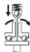
BypaybIupa aHany MOMeTIne Tayendi axbIpaTy tipkecimi 6ap, on 6enrineHren dHaapaOnda peTteJIe. On opnatbIinaH aHaHny MOMeTIhe KeTeHHen KeiH icke KocblaBl.
Hcy: erep 6ypaaybIbI Kepey aanTepImeH 6ipre naJaHaHcAHy3, aJbImeKepHey TypaKaHbIPfBbIH icKe Kocy KaKTe.
3NeKtp KypaBbH Kocy ywiH axkblpaTkblTbl (13) TipenreHwe 6acblb3.
3Jektp KyaPJIbI opHaTbIINFaH aHaNy MOMHTiHe JeKTeHne abTomaTTbI Tpyde eweidi.
Akkipatkbii (13) Mep3imieH 6ypbH 6ocatbnca, andbH ana ophaTbInfah aHany MOMeTIne XetneIi.
PaindanaHy 6oibHua HycKaynap
AkkymyIaTOpdbI 3neKtp KypaImHeKe3 KeIreH KymbIcTapdbI (MbICanbl, opHaTy, KbI3MeT KepceTy, T.6.) 6actay anDbIHda, coHdai-ak, 3neKtp KypaIaNbI
TacbImaIay KHe caKay Ke3iHne WbIFapbIbI3.
Kockbl/0eipriuke Ke3deiCOK TnIO JapaKaTTaHy KayniH TydbipaDbI.
3NeKtp KypaIbIH CombIH/6ypaHaDaFa TEK oWipinreH Kynde calbIbI3. AInHaJIbIN KaTkaH Kymblc KypaIJaIpaBl cbIPfbl IN KeTyI MymKiH.
Ainany MOMENTH peTey (G-I cypeTepiN kappaIbI3)
Bypay MOMENTi axbipaty tipkeciMHcepinnepePiH anDbH ana kepiicih 6aIaNbIcTb 6oIaIb. Axbipaty tipkeciM OH xHe cOJxakKa aHaHny Ke3Ine opHaTbINFaH bypay MOMENTHE XETKeHHEN KeIH axbipatbIaNbl.
Keke 6byay MOMENTIOpHAty yuIn TEk 6ipre KeTeK3iIeH peTteriw Kypalbl (30) naDanaHbHbI3.
3neKtp KpyaIbIHdaFbl bICbIPMaHbl (7) apTKa KapaTOnblK XblJXblTbHbl3.
ANGLE EXACT 2|3|6|7|8|15|17|23|30
AnTbI KblpIbI DeH6Ee KInTI (31) aImaIbI-cAmaJIbI acnapanKa (30) caJIbI, OHbI bary bpyaHbI.
Kopnyc caHbInaybInHa kii dHeec Jep (peTteriW aai6a
(32)) Tipkecimde KeipireHne, peTteriW KypaIbI (30) ocbl DeHec Jepre KoBbIN 6ypaHbI.
ANGLE EXACT 14CF | 22CF | 29CF
CaTbIn aIbIHFaH XblJXbITbIINFaH cbIpFakTbIK cyNnOpT TypaIbI MAniMeTTEpre Ha3ap aydapbIbI3 HeMece DeIaNdaH cypaHbI3.
Carat tiniHin 6aftbImen 6ypaFaHa yNKeHipeK 6ypay MOMHTi, an carat tiniHin 6aftbTbHa KaCbI 6ypaFaHa KiiupeK 6ypay MOMHTi naDa 6oNaDb.
PeTteriI KypaIbI (30) IbIfapbIbI3. TipKecimIJIacTaHydAn Kopfay yWIn bICbIPMaHbI (7) KaITaHaN aIFKaJbIJKbITbIHbI3.
Hyckay: KaKeTTi peTey 6ypaHdaIb KocblbIMhIH, TyPiHe 6aIIaHaBCTb 60aIaIb JxHe npAeTKaIbIK TAgipNbe EtKl3y apKbIb aHbIKaTanyI TiNc. CbIhak 6ypan6ekitydi DInHAMOMeTpNI KIITnEH TeKcepiH3.
AHHany MOMENTIH TEK 6epinre H Kyat dHana3oHbInda peTtei3, aHTnece axkbipaty tipkeci Mxmbic icTeMeiDi.
AHHany MOMENTHIN, petreyin 6enriney
ANGLE EXACT 2|3|6|7|8|14CF|15|17|
22CF|23|29CF|30
KepeTteneH aHany MOMENTepiH 6nriye ysiH 6enriye weh6epiH (17) 6acka TycTi 6nriye weh6epimeH anMaCTbIpyfa 6oanaBl.
Erep 6iphewe EXACT 3neKtp KpaIbH 4,5 Hm aHany MOMENTIMeH naJaIaHaHcaHbI3, KbIbIy TycIte 6bniriney Wne6epiH 6pyay MOMeTIH 6bniriney yWIn naJaIaHaYf aBnab. Erep aHaHny MOMeTI 7,5 Hm 6onFaH 6acka EXACT 3neKtp KpaIaDaIbH 6acka MoNTaJxay aMafblHa naJaIaHaHcaHbI3, 6acka TycIte 6bniriney Wne6epiH (kapa, Kek, Jacbl He capbl) ablIn, ocbI aMak yWIn aHaHny MOMeTIH 6bniriney iJ3 kepek. Typni TYcTeri 6bniriney Wne6epneri opHaTyuBnapFa Kemek petInde 6epineDi, olap ap 3neKtp KpaJIbHa KaHaJa aHaHny MOMeTI opHaTbINFaHbIH aHbIKayfa apHaJIFaH.
Bentirey weh6epin (17) kya 6ypaBiy napaBIme, KanakamaH HeMece yKcac 3aTneh 6acbl KoBlbI3.
3NeKtp KpyaIbIH aPdaiBIM 6eIriye WeH6epiMeH naJaIaHaBII, KopnycblH IaH MeH NaCTaHydaH KopFaHbICnEH KaMTaMaCbI3 etiH3.
Xapbik, HnoDTbI HnDnKaTOp

AkkymyIaTOp 3apIbI DeHreinIH INHdkaTopbl
AkkymyTopbl (11) 3apJdTay KaKet 6oIfHa, KapbIK MIOBtbl HINIKaTOp (10)
Jacbl TycneH JbIbIbIbKtaI, Dlb6bcTbIK CnHaH 6epineJI. CoaH KeiH 6-86paHdIb I Kocblm FaHa Xacay MymKiH 60anaJI.
ErepKapbIKDnOdbkb3blTycneHJxHaC6ypaHdaIbKocbIbIM yWIn KyaATbIH JxekTkiNikci eKeHHiH HEmec3NeKtp KypaIbIH apbIK KxKTeMe TycKeHH 6inDipeJI.3NeKtp KypaIbIH 6yDaH 6bnai icKe Kocy MymKIN 60MaJbI.1cke KocbIyduh KopraTbIH Kynbln AKKymJYTOP 3NeKtp KypaIbIHah WbIfapbIbIN, 3apdTaIFaH aKKymJYTop caIbHfAhu 6bcEndi 60bln Kaanbl.
ErepKepeHey aadantepimEn XyMbIc icTeceHi3, Kbl3bIn TYCTi KaBkDIOJb INHdIKaTOP (10) apTbIKXyKTeMeHH, TYCKeHI KepceTei.
KapbIKIINoITbI INHdNKaTOp (10) Kbl3bl TycneH
KblblblKTaca, 6yI 3NeKtp Kypalbl Kbl3bl, OHbIH ICTeH
blkkahh 6linipei. 3NeKtp KypalbH KaTa icKe kocyaH
6bpH JxblblkTay Kbicka Mep3imde aBtOMaTbI Typde
ceHrHeHwe KyTHi3.
Op 3apJtafAHn KeIH 3neKTp KypaIbHbI naiDanaHy Mep3imH aiTapJIbIKTa KbcIcKApByi AkkMyIaTOpDb ayictbyKepeKtirih6inipei.To3raH akkMyIaTOpnapdb3aHdb/ enre TEN HcyKaamnap 60bHwa KaDeere JapaTbHbI3.

BypaHdaIbI KocblbIMdApdbI INHnKaTObI
AaIbIh aIa opHaTbIaNFaH aIaNaly MOMeTIHe KTeKHeH e KeiH aXbIpaTy TipKecimi aXbIpaNaIbI. XapbIK dIONbI HINKaTOp (9)
JaCbI ITYcNeH JaHaDbl.
Erep aIbH ana opHaTbIHaan Hany MoMeHTHe XeTnece, KaBkIIOITbIH NdkaTOp (9) Kbl3bl TycnEH XaHbIn, Dbl6bCTbIK CnHAn 6epinei. Bypan 6ekitydi Taftbipet opbHday KepeK.
KaetaHyaHan KOpFaHbIc
BypaHdaIbI KocblbIMda axbIpaTy tipkeciMi 6oCaTbIcA, KO3FaTbKbI IeJeI. KaTia icke Kocy TeK O,7 cekyHdTbIK y3iInTeH KeiH MyMKiH 6oJaIb. OcbIaNla KaTTbI 6ypaHaIbI KocblbIMdapdbIH KaTe TaPbIyBuHa JxOJ 6epMeCi3.
Bypbltbok omMaIb6actneKtJxblXbity
ANGLE EXACT 2|3|6|7|8|15|17|23|30
Bpybltbik oMambl bactnekti (3) xanbl ceriz knyre aybictipyfa 60ana.
3nektp KypalbH aibp Taipi3i KintneH (6) 6ybp 6actbI
phaneHTIH KINT Ka3bIKTbIFbHJa5MbKtan YCTaHbI3.
3NeKtp KypaBbIH Kopnyc Ka6bIFbIHda KbicyFa 60nMaIbI.
21 | Ka3aK
Aibip Tepi3di KintneH (4) KIIT Xa3bIKTbIFbHda (19) Xaanna raKaHb6ocatbHb3. BypblTBK OImaJIb 6actNeKi (3) Kaaynb KyIe 45^ KaXbIIJXbITbIN, aBip Tepi3di KINTneH (4) KIIT Xa3bIKTbIFbHda (19) Xaanna raKaKaHb KaNTadaH TapTbIN KOIBHb3.
By peTae aHbip Tepi3i KInTneh (6) 6ypbiu 6actb fnaHeueke Tipen typbHb3.
ANGLE EXACT 14CF | 22CF | 29CF
CaTbIn aIbIHFaH XblJXbITbIHaH cbIpKaTbIK cyNnOpT typaBImaIImeTTpe Ha3ap aydaPbIbI3 HeMece DeIaIaH CypaHbI3.
XapbIKIIOIDtbi Jxmbic IaMbIH XbIIJXbITy (J cypetIH KapaHb13)
ANGLE EXACT 2|3|6|7|8|14CF|15|17|22CF|23|29CF|30
Bérlirinye shenbepin (17) kya 6byaybIu npaFbIMeH, KaakwamEn HeMece yKcac 3aTneh 6bacn KoBHb3. Cepinneni TeXeriw CaKHaHb3 (33) cepinneni texeriW caKHa KbiCKbIbIMeH apTka Kapai Kopnyc cbiptbHa XblJKBtBhlB3.
JapbIKDIOQTbIXyMbICIaMbIH(18)Jka6aTbIHJapbIKDIODbI YCTaftbIbHbIH(16)ekiJxpabTcBcIHdaehiKaalaybIkyre KeTIPyRE 6oJa. JApbIKDIOdTbIXyMbICIaMbIHdAfbI Ka6eBbDi3aKbIMDaMa, Tnicti Kopnyc Ka6bIFbIHdaFbI KybICa
(34) 6yKTeMeJxblJXbTbHbI3. JApblkDIOITbJxMbIC
UaMbIH (18) XapblkDIOBbYCTaFbUHbIH (16) eki Kopnyc Ka6blfImeH KaTadaH KajbyIn KoJIbHbI3.
Cepinneni TeXeRiWi CaKHaHbI (33) KHe 6eBriiny WeHbepiN (17) KaTadaH AnEpiKi KyIHe KaTapblHbI3.
TexHnKaIbIK KyTIM XHe Kbl3MeT
KbI3MeT KOpCeTy XeHe Ta3anay
AkkymyITopbI 3neKtp KypaImeH Ke3 KeIReH KymbIcTapbl (MbICaNbl, opHaTy, KbI3MeT KepCey, T.6.) 6actay andbInDa, coHda-ak, 3neKtp KypaNbl TaCbIMaNlay XHe caTay Ke3iHne IbIFapbIHbI3.
Kockblu/oeipriuke Ke3deiCOK TnIO JapaKaTTaHy KayniH Tydbipadbl.
Kakcbi api ceHimdi JyMbic icTey ywiin 3neKtp Kypanbl MeH JeienTeKiW TecikTi Ta3a YCTaHbI3.
3neKtp KypalbIM MaIay

MaJnarfbi:
Bepinlc Kopa6bHa aPnHaFaH MaJ (225M)
Ohim Hemipi 3605430009
Molnokot Maibl
SAE 10/SAE 20 MoTOp MaJIbl
- AIfaKbI 150 JxMbIc cafTaBHaH KeiH 6epiNc Kopa6bH JeHIN epITKiWIIe H Ta3anaHbI. EpiKiw eHdipyUicIHn PaJdaIaNHy KHe KaDEre JXapaTy HcCKaynapBH opBHaHbI. BepiNc Kopa6bHbEepiNc Kopa6bHa apHaJIraH Bosch MaIbImeMaINaHbI. AIfaW pet Ta3aIaydAnH 6actan Ta3aIay npOeDypacBH eP 300 JxMbIC cafTaBHaH KeiH KaTanaHbI.
-AkbyapTu tipKecimHIn KByIbKbImaBb6bnIKeTepiH 100 000
6ypan 6ekity apekeTIHe KeIH 6ipHeWe TaMbS ASE 10/ SAE 20 MOTOP MaBIMe MaNbAbl3. CbPnAHTbH Kahe
aHaMaJIbbl 6bnIKTePdi MOINKT MaBIMe MaNbAbl3.
KaFdaB 6oIFaHda TIPKecIMHIn TO3FaH-TO36aFaHbH
TekcepIn, KaTaNanhyuBbIK NeH dAnikke cep
etINMeReHIn Ke3 JeTKi3iH3. CoaH KeiH TIPKecMHIn
aHaNy MOMeHTIn KaTa OPHAry KaKcET.
KbIMET Kepcety XeHe XeHDey XyMbICTapbIH TEk MaMaHap MeH daiBihBifbI 6ap KbIMETKePnep opbHdayblTic. OcbJaMaa 3JekTp KypalbIH, Kayinci3di rCaTanaabl.
KkineTti Bosch cepBnti opTaIbIbI 6yI JxMbIcTapdbI KblJam KHe ceHIMdi Tpype OpbIHJaDbI.
MaJnafbIiXxHe Ta3aIaNbIi 3aTtApDbI KOpuFaH opta yuih Kayinc3 xKoMhen KaDeTe JkapaTy KaKeT. 3aHdbIK HycKaMaNapDbI opbIHdaHbI3.
TyTbIHybIfKa bI3MeT KepCety XaHe naIdaIaNy KeHecTepi
Kb3met Kepcety We6epxHaacbI eHIMdi JxHNey XHe KYTy, coHda-nak Kocalkb6eNweKtep TpyaIb cypaTapfayayan 6epei. Kapby cb36abapbl MeN Kocalkb6eNweKtep TpyaIb mJImeTTepI TeMeHderI MeKeHHaJa TaBacb3:
www.bosch-pt.com
Bosch 6aFapnaMaCbI KeHc TObb 6i3DIn HEmIp KHe onapdbH KepeK-JkapAkapbI TypaIbI cypaKTapbIbI3Fa JKayan 6epei.
CypakTap KOIO XeHe KocanKbI 6oJIweKtepeTancbIpbic 6epy Ke3IHDe MInDeTTI Tpyde OHIMdIH 3aybITbIK TaKTaHacblHaFbl 10-caHbI eHIM HEmipH Jka3bl3.
HniPyiTi TaIaIITapBm HOpMaIapBbHbIcKaTaNbIMe
3JIeKTP KpaIbH XeHDey XHe KeiNdi Kbi3MeT KepCTeY
6apblk MemKeTep ayMaFbHnDa TeK "Pobep T Booi
fipMaIbIK HeMece aBTOpHaZaunHaHFaH Kb3MeT KepCTeY
opTaIbIKTapBHaObpHdAnaDb. ECKEPTY! 3aHcb3 JQoJMeH
3ekiHReh OHIMdepi NaIaIaNHy KayinTi, DeHCaybIFbIH3Fa
3HN KeNTiPy MyMKIn. OHIMdepri 3aHcb3 Jxacay JxHe
tapaty AkIMwiIK XHe KbIMbICTbIK TApTIN 60bIHwa
3aHMen KydaIaNAbI.
Ka3aKctan
TybHyybnapraKeHeC6epyXaHepMdApdbiKa6blday optaBlfbl:
"PoBept Bous" (Robert Bosch) XUJC
AJImaTbI K.
Ka3aKCTaH Pecny6nIkaCbI
050012
Mypar6aebK.,180y
"TepeMec" BO, 7 Ka6aT
Ten.: +7 (727) 331 3100
a c: + 7 (727) 2330787
E-Mail: ptka@bosch.com
CepBnCTiK KbI3MeT KepeTy opTaIbIKTapbl MeH Ka6blIay nyHKTePiHi MeKeH-JaHbI TypaIbI ToJIbIK JxHe 03eKti aKnapaTbI Ci3: www.bosch-professional.kz pecmN caTTaH ana aIaNcbl3
Kdere kapaTy

3neKtp KpyapIaIapIbI, AkkyMnyTopIapIbI, KepeK-JapaKaTapIbI JxHe opay MaTePnAaIapBIn 3KOIOrnaIbIK TypfblaH
Dypbic yTnIIN3aunnaJayf TaTncbpy KepeK.

3neKtp KpyapIaIapDbI JxHe aKkyMnyTOpIaPdbI/6bTapeaIapDbI yKoKbICbHa TaCTaMaHbI3!
TekKaHaEOeNepiYwH:
Eypona 2012/19/EU epexeci 6oBbHwa Jxapamcb3 3neKtp KypaIapbl XeHe Eypona 2006/66/EC epexeci 6oBbHwa 3aKbIMdaIaan HeMece ecki akKymyIaTOp/6aTapeaIap 6eNek KHNahbln KdJeE kapaTbIybl KaKeT.
AkkymyTopnap/6aTapeenap:

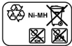
Ni-Cd: HnkeJIb-KaIIMn
Ha3ap ayadabihb3: 6yI aKKymJrTopnapdbH Kypamblda KaDMn, eTe ynafbli, aybip MeTaN 6ap.
Ni-MH: HnKeJIb-MeTaJIngIpdI
Româna
Instruţiuni de siguranta
Acumulator defect Inlocuii accumulatorul
Lubrifierea sculei electric
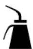
Lubrifiant:
Vaselinà specialà pentru angrenaje (225 ml)
Numár de identificare 3 605 430 009
Vaselinà Molykote
Ulei de motor SAE 10/SAE 20
Service scule electric
Strada Horia Macelariu Nr. 30-34, sector 1
013937 Bucureşti
Ni-Cd: nickel-cadmiu
Atentie: Acesti accumulatorati contin cadmiu, un metal greu extrem de toxic.
ToH He ne pOxOJa3a pa3BnBaHe Ha BnTHoBNcEHNHeHNA.
EneKTPoHnCTpyMeHTbT He nOIOxOJaIa 6bDe I3noI3BaH KaTO 6OpMaAsHa; 3a Da I36eHHe TpaBMn HcTeH, HNKOra He I3NoI3BaIte eJeKTPoHnCTpyMeHTn C I3KNIOUbaIcBedeHNHTeI 3a npo6uBaHe.
H306pa3eHH eIeMeHTn
HomepnpaHToHa enemEnHTe Ha eneKtpOnHcTpymenta ce OTHacdo n3o6paXeHnraTa Ha cTpaHnCtne CfHpynPte.
(1) Pa6oTeH INHCTpyMeHT (HaIp. HaKpaHnK 3a 3aBnBa-He)
(2) He3d0
(3) brrnoBa 3aBnBa a rnaBa
(4) Taeuen KIIOU c pa3mep 27 mm
(5) CkocenHnIOBbpxHOCTn3a3axBaUaHe CraeueHKnHuaΦnaHeuHa bTNOBbTa rNaBa
(6) Γauehen KlnHou, pa3Mep 22 mm
(7) Пльзага за п体现在датулираима на Вьртушю мостент.
(8) Cko6a 3a OKaYBaHe
(9) CBeToIIOu3aBbBaHe
(10) CBeToIIOJEN HINIIKATOp 3a CTeNEHTa Ha 3apeJeHocT Ha akymyIaTOPHaTa 6atePnIa
(11) Akymylatopna 6aTepe n C APT-üekep
(12) Ocbo6oxkaBaun 6byToHn 3a akymyNaTopHaTa 6aTepe
(13) Пусков пэрьс Bau
(14) Праватул Stа посокata на Вьртеше
(15) KaHann3a3axBaAaHe Na ckObata 3a OkaBVe
(16)ДьржачизCBetoIOIoNTe
(17) MapKnpoBbueH npbCTeH
(18) Pa6oTHa naMna
(19) Повьрхости за захвацане с клюн Ha xоленpoВаразгайka
(20) KoHTpa-raIka
(21) 3aPdHo yCTpoNCTBO
(22) Ⅲeencen
(23) 3eJIeH CBeToIOnIOeH INIINKaTOp Ha 3apAIIHOTo yCTpoIcTBO
(24) YerBHeN CBTeOJIoOeH INHnKaTOp Ha 3apIaHTo yCTpoiCTBO
(25) Kynnyhr 3a aanTep 3a HanpexeHne Ha 4EXACT
(26) Lükep D-Sub
(27) BnHToBe Ha igeKepa D-Sub
(28) Aaantep 3a Hanpejekne
(29)БьрзOCMeHEn NaTpOHHNK
(30)Интуремптза рergyларе
(31) ⅢeCTOCTeH eKIIHO
(32) Perylinpaansck
(33) 3erep-uaib6a
(34) OTBOPB KOpnyca
(35) PboKoXBaTka (nOIOIpaHn IOBbpxHOCTN)
I3o6pa3eHnTe Ha 9HyrpyHe n OHncAHTE DoBbHNTeHH npHCnocOBeHH He ca BKnIOUeHH B cTaNdaptTHa OKOMNNEKTOBA HA ypeHa.3HepnateneCnCBk Ha DoBbHNTeHH npCnocOBeHH MoKTe Da HAMepHTe CbOTBEtHO B Katanora Hn 3a DoBbHNTeHH pNcNoCObeHH
TexHHueckn DaHHN
Ppomnwnen akymyntopeh brrnoB bHNTOBepT ANGLE EXACT 236
KataJoxen HOMep
060249064706024906560602490652
234|Блгарский
Помишен akymunatopeн btrnoB bHTOBept ANGLE EXACT 2 3 6
| Мakc. Вьртах MOMENT pri NBpdi/Mekn BnHTOBN cbe-DinHeHЯ NO ISO 5393 | Nm 2/2 3/3 6/6 | |||
| Скорост на Вьртыне на праzenхов n0 | min-1 | 110 | 420 | 650 |
| Номинално наразжени V 9,6 9,6 9,6 | ||||
| Посoka на Вьртынe | ΩΩ | ΩΩ | ||
| Маса съласно EPTA-Procedure 01:2014 kg 1,0 1,0 1,0 | ||||
| Вид зашита IP 20 IP 20 IP 20 | ||||
Ipnmuien akymunaTopen bflnoB BnHTOBept ANGLE EXACT 7 8 15
| Катохен Home | 0 602 490 669 0 602 490 651 0 602 490 650 |
| Марс. Вьртыц мочent при Тьрди/Meки ВиHTов сбe-dинения по ISO 5393 | Nm 7/7 9/9 15/15 |
| Скорост на Вьртыне на праzenхов n0 | min-1 110 420 250 |
| Номинално наразжени V 9,6 9,6 9,6 | |
| Посoka на Вьртынe | ФОФО |
| Маса съласно EPTA-Procedure 01:2014 kg 1,0 1,0 1,0 | |
| Вид зашита IP 20 IP 20 IP 20 |
Помишен akymunaTopeн bIroB BInrTObeR ANGLE EXACT 17 23 30
| Катоюжен Homep | 0 602 490 675 0 602 490 673 0 602 490 671 |
| Марк. Вьртыц мочent при Тьрди/ meки виHTови сbe-dinенья по ISO 5393 | Nm 17/13 23/20 30/28 |
| Сторост на Вьртени на пазенхов n0 | min-1 560 320 220 |
| Номинално наразожения V 14,4 14,4 14,4 | |
| Посoka на Вьртени | ФОФО |
| Маса съласно EPTA-Procedure 01:2014 kg 1,5 1,5 1,5 | |
| Вид зашита IP 20 IP 20 IP 20 |
Пюмшилен acумунatopeн bгов винтоBERT ANGLE EXACT 14CF 22CF 29CF
| Катоюжен Home | 0 602 490 690 0 602 490 693 0 602 490 691 | |||
| Мakс. Вьртыц MOMENT Тьр dio завивае с десен xodiumA) | Nm | 10 16 20 | ||
| Овороти на праzenхOD nO pri duceнхodiumA) | min-1 | 340 | 440 300 | |
| Номинално наразожения V 9,6 14,4 14,4 | ||||
| Посoka на Вьртени | ΩΩ | ΩΩ | ΩΩ | |
| Маса съласно EPTA-Procedure 01:2014 kg 1,0 1,5 1,5 | ||||
| Вид зашита IP 20 IP 20 IP 20 | ||||
A) CkopoctTa n BbptTnI MmOte NpN BbptHe HaJIBO Ca IIO-HNCKH 3a Te3n EneKtpOnHCTpyMeTHn. BcJeCTBHe Na npEpaBaTeHnOto YncNo Ha IILOCKOTo 3aDnBnKBaHe CkopoCTTa Ha BbptHe N BbptTnI MmOte Ht Pa6OTHnIHCTpyMeTc Pa3JIuHn.
| Ni-Cd akymatopha 6aterma | 9,6 | 9,6 | 12,0 | 12,0 | 14,4 | 14,4 |
| Каталожен Homep | 2607335877 | 2607335659 | 2607335879 | 2607335375 | 2607335881 | 2607335655 |
| Бр氧 клетки | 8 | 8 | 10 | 10 | 12 | 12 |
| Акymаторно наразжения | V | 9,6 | 9,6 | 12,0 | 12,0 | 14,4 |
| Кацитер | Ah | 1,8 | 2,4 | 1,8 | 2,4 | 1,8 |
| Маса сълacrno EPTA-Procedure 01:2014 | kg | 0,45 | 0,50 | 0,65 | 0,70 | 0,70 |
PepOBHn npOBePARBaIte cbCToAHHeTo Ha cKo6aTa H KyKaTHa NpOEMHOTo PnHCnOC6bHeHne.
3apekdaheha6atepnaTa
Yka3aHHe: 3apAHNy UcTpoCTBa H aKymyNaTOpHn 6aTeepn He ca BKNIOUeH N BOKOMJIeKTOBkata.
LecenbHa BaWnna eNeKTponHcTpymeHT moKe da ce pa3- nUaBa oN3o6pa3eHHa qnHyprte.
YBepete ce, ye 3apAHHOTO yCTPOIcTBO n AkyMynaTopHata 6aTePnca naDxOJaun 3a 3axpaHbauata Mpeka Bbb Baata cTpHa.
3apndno yctpoicTBO AL 2450 DV (Bx. fhr. A)
BkHoueTe uenCeJa (21) Ha 3apJdHOTo yCTpoiCTBO (22) KbM eEkeTpueckaT MaPexa H NocTaBeTe aKymyNaTopHaTa 6aTepeN (11) B IpaBnHaTa P03uYra B rHe3I0To 3a 3apeXDaHe Ha 3apJdHOTo yCTpoiCTBO.
PnnoctabHne/H3BaXdaHeHaakymnaTophata6aTepeHne H3non3BaTc cHnA. AkymnaTopHn 6aTeepnC KOHTaKTHN KJIeMn APT (Akku Pack Top) ca KOHCTpynpaHn Taka,Ye MoRaT Da 6bDat NoCTaBeHn B eENEKTPOINHCTpyMeH Ta HIII 3apJNDHOYcTPOINCTBO CaMo B IpaBnIHATA NO3uZIy.
3eelenrT cBeToNDIOg (23) 3aNoOyBa da Mra. TOBa yKa3Ba 3a npotuHaTe Ho 3apJeH ToK. IpouecBt Ha 3apeJdahe Cnpa aBTOMaTHUHO, KOrato akymuaTOpHata 6aTepeRce 3apei HAnbIHo. Korato 3eelenr cBeToNDIOc cnpe Da Mra n 3aOnueHe da CBETn HnpeKbChATO, IpouecBt Ha 3apeXdaHe e npNKlouHIn. IpozBuYaba 3ByKOB cHnAcl CpOdbLnKHTenHoc Tnp6bl. 2 cekynDn, yka3BaU 3a PbNHO t 3apeJda He ha 6aTepeRyta.
HnpeKbCHaTO CBteHe Ha cepBHeNc BcTeOnIO (24) yka3Ba 3apeJdaHe C hAmaleh 3apJeH ToK. Korato cepBHeHrT CBeToIOd MnIa, 3apeJdaHe Ha akymyNaTopHaTa 6aTePnI He e Bb3MOxHO.
IpeKn -PnpuHHN 3a Bb3HnKBaHe N haunHn 3a oTcpaHBAhe
PpnuHnA Pmou
CbeToHIOHNHTe HnHnKaTOpHe CBeTAT
UeIcEnbT ha 3apAINDHO yCT- BkapaTe (doKpaI) uencela poiCTBO He e BkapaH B KOHTaTa TAKTA (npabnHo)
Kohtaktb, 3axpaHbauaKa- PpOBepe 3axpaHbauoTo 6en nn 3apJHOTO yCTPOIC- HnPpeKeHne, aKO e Heo6xoTBO ca DepeKTHN 3aHeCEte 3apJHOTO yCTPOICTBO 3a npOBepka B OTOPI3npaH cepBn3 3a enekTpOINCTpymEnTH Na Boos
He e Bb3MOxH0 3apeXdahe
Tempepatpata Ha akymyla- Tophata 6atepy He e B do- nyctMnHHTepBaI BaKymlaTOpHata 6atepy BdoNyCTMnHaTepeatypeH nHTepBaI MeJdy O ^ C (32^) n 45^ (113^) uez ox- naKdahe nn HapraBaHe
Kohtakntte Ha akymnatop- PooHCTeTe KOHTAKTte Ha haTa 6aTePnca 3ambpcenn akymnatopHaTa 6aTePn, Hapr. Upe3 HeKoJIKOkPaTHO
Ppunna Pmou
| То язвадан e Варвае В ГиздOTO, респ. заменete akymалаторна в батерия | |
| Актулаторна ватерияе дебъкtnа | Заменete akymалаторна в батерия |
| Актулаторна ватерияе стосявени (празвени) | В��айт(e(hально) akту- латорна ватерия в Гиздо- TO |
Tokon3npabnten(Bk.Фнr.B)
ANGLE EXACT 2|3|6|7|8|14CF|15|17|
22CF|23|29CF|30
Yka3aHHe: AnTePhaTnBHO INyDcTpnaJIHnTe aKymNaTOpHN BInHTOBePTN MoTa 6bDaT 3axpaHbAHn N OT TokOn3nPaBn-TeI.
IeIcBbT ha BaIIIN eIeKtponHCTpymeHT moKe da ce pa3- Iuaba OI 306pa3eHHa fHyprnte.
Ybepete ce, ye Tokon3npaBnteIe nOdoXoJa3a HanpeKeHneto Ha 3axpaHbAaTa MpeKa BbB Baata CtpaHa.
OcbenOT Tokon3npaBHTe4EXACTnnoxOJa7z3axpaBauKabEn,ceHyjdaTeNt aanTep 3a HappeHne,koTo e cbcbIto HOMHaHNOHappeHne,KaKTo Ba7nBuHTOBePT.
HanpexeHnTo Ha ToKo3npaBHTe (CBTeOndoen HnDKaTOp) Tp8bda CBoTBcTcBa Ha HanpexeHnTo Ha BnHTOBepTa. Toko3npaBHTeT e npedHa3Naueh Ca-Mo 3a INyDCTPnaJInHe akymylaTOpHN BnHTOBepTu Ha Boi ot cepinTe EXACT, ANGLE EXACT u BT-EXACT cHa-npexeHne Mekdy 9,6 V n 14,4V. B npotnBeH cnyaB cb- IeCTByBa ONaCHOT OT Nocap J EKCnNo3n.
BkJIIOUbaHe KbM H3TOUHnK Ha TOK
Yka3aHHe: MoJI, o6bpeHe BHNMaHHe, ue B cbCTOHaHe NaIOCTaBkA B eIeKtPOnHCTpymEHTa He ca NocTaBeHn HTo aKyMylaTOpHa 6aTePnH, HTo aAnTep 3a HanPexKeHHe.
HnKora He ocTabaIte akymyNaTOPHN 6aTePnN 3a cbXpaHaBaHe B akymyNaTOPHN eNEKTPOHCTpyMeNT.
AkyymnatoPHTe 6aTeepn H3IbpxkTpo-DbIro Ice 3apeJdTpo-6bP3O, KOrato ce cbxpaHbAT 3BaJeHN. KOrato npoBnKHTeHIO BpeMe He cTe n3I0n3BaHn akymyata TOpHATA 6aTeepn, He 3a6pabTne ppeH daЯ n3I0n3BaTe daЯ 3apeHte.
3apekdahe ha akymnatohpata 6aTepe
Ipezi da nocTaBnTe akymyIaTOpHata 6aTePnB eEnkTPOINHCTpyMeHTa,ЯЗapeTeC noDxOJaIIO 3apJHO ycTPOIHCTBO.3aTOHOTo OINCaHHe Ha npOeca Ha 3apeXJaHe MOJI npOyeTe pKOBODCTBOTo 3a ECKPiOaTAuHa Ha 3apJHOTo yCTPOIHCTBO IN CbOTBeTHHe Yka3aHnB HAcTOnIooT o pKOBODCTBO (Bk.3apeXJaHe Ha 6aTePnJaT“,CTpaHnua 236).
AkymylaTOPHata 6aTepeHIMa NTC tempeHypeH KOHTpO, KOIto PO3BOJRABa 3apeJdaHeTo cMoB TeMpeHaTpHnIH TepBaI mKdy O ^ C (+32^) n 45^ (+113^) .IIO TozH naHH ce yBeJIuAba JbIroTpaHNoCTHa akymylaTOPHata 6a
Tepn. Pnp npaBnHa ekCpnoaTaun akyMynaTopHata 6aTePn moKe da 6bDe 3apeKdHa do 3000 nTn.
HobnnpoBnKInHo BpeMe Hn3nO13BaHa akymyataropHa 6aTePnIgDcTnIg nKnAaCtET eBa cIeI npn6I.5 uKnbHa Ha 3apeXdaHe n pa3peXdaHe. AkymyataropHnTe 6aTePnIg Tp8BaJa 6bDat npe3apeXdaHn CaMo KoRATO CBeToNDnHrT INdNkAtop "CbctOraHne Ha 3apeXdaHe Ha akymyataOpHaTa 6aTePnIg" Ha eJeKtpOnHcTpymEHTa CBeTnc YcepBeHa CBeTIHa.
IocTabaHe n3BaXdaHe Ha aKymyatopHata 6aTepeHn
IocTaBeTe IpeBKnIOUoyBaTeTn 3a NocOKaTa Ha BbPteHe (14) BcpeHaNo3nIyra. Toba 6bnKnpa NpckOBnI pKeBcBauch (13) Ha No3nIyra "N3Kn", 6naOdaPeHne Ha KoTo Ce npedOTbpaTBA BkIoUByAHeTo Ha eNeKTPOINCTpyMeHTa NO HeBHMaHne.
BkapaTe 3apeDeneta akymnaTopha 6aTepeYra (11) BpbKoxBaTKaTa Ha eNeKTpoHnCTpyMeHTa.
BnHmAbaTe Da NoCTaBte AkymyIaTOpHaTa 6aTePnBa H npaBnHaTa POnu, KaKTo N OcBo6OxJaBaUHTe 6yToHn (12)Da Bn3aT B pbKOxBaTKaTa Ha eNeKTpOnHcTpymEHa C OTcETJIbNO ppepaKaBaHe.
Pnnoctabare/3BaxdaheHaakymnaTophata6aTepeHne H3non3BaTe cna. AkymnaTopHN 6aTeepn C KOtAKTHN KJIemn APT (Akuu Pack Top) ca KOHCTpynpaHn Taka, ye MoTat da 6bDat noCTabeHn B eEKeKTPoHnCTpymEn Ta IIIN 3apJNDHOYcTPOIcTBcMoB INpaBInHata No3n-
3a da n3BaDnTe akymyNaTOPHaT6aTePn8 (11) HATNCHeTe OT dBete cTpaHn OCBO6OxKdAaUHTe 6byToHn (12) n3DbpNaTe akymyNaTOPHaT6aTePn8 HaOny O pBkoXbTaKaT.
IocTaeHHe n CbAJIe Ha aIaITepa 3a HAppeKeHHe (Bx.Φn.r.C)
ANGLE EXACT 2|3|6|7|8|14CF|15|17|
22CF|23|29CF|30
Izhepete noxdoxo3a Baushia elektponHctpymEnT aan-ter 3a HanpexKeHne.
Aaantepnte 3a Hanpejehne ce pa3nuyabat cnopei HanpejehneTo no zBetaHa Kopnyca Ha D-Sub ukepa (26).Kopnycbt Ha D-Sub ukepa 3a Hanpejehne 9,6 V hma CBeTIOcH nBt, a To3n 3a 14,4V uehen ZbI.
KopnycbyHa aanepa (28) MoKeJa ce MOHTnpa HnH DeMOHTnpa cAmo npn N3KJIoueH TOKOHNpabNTen HnN npn OTKaueH OT TOKON3npaBNTen igekep (26) B nHdyctpnaHnHa kymynaTopen BnHTOBePT.
IocTaBeTe IpeBKnIOUoyBaTeTn 3a NOCOKaTa Ha BbPteHe (14) B cpeHaNo3nUy. Toba 6nOknpa NcKOBnI pKeKcbuA (13) Ha No3nUy "N3Kn", 6naOdapeHne Ha KOeTo Ce npEIoTbPaTBA BkIOUbaHETo Ha eNeKtpoHnCTpyMeHTa NO HeBHMaHne.
CneTbA BkapaTe KOpnyca Ha aDantepa (28)BpbKoXBaKaTaHa eNEKtpOnHCTpymeHa. BnMabaiTe Da nocTabre aAdantepa B npabHnHaTa No3uYra, KaKTo HOCBO6OxDaBaUHe Te 6yTOHn (12) Da Bn3at B pbKoXBaTKaTa Ha eNEKtpOnHCTpymeHa COTHTINBO ppepaKaBaHe.
CneTobA BkHouTe 电keepa (26)Ha noDxoJnna 3a Ba- 1eKTPoINHCTpyMeHT aanTp 3a HanpeKeHHe B KynnyH
ra (25). 3aterheTe uekepa (26) KbM KyIyHra (25), KaTo 3aterHeTe Ha pbKa DbaTa BnHTa (27).
3a da n3BaInte aIanTepe 3a HnapeKeHne, pa3BnTe DbTa BnHTa (27) Ha uekepa (26) Ha n3KJIuOeHnTOKoN3npaBnTe I n N3dbpnaTe uekepa ot KynnyHra (25).
CneTToBaI npHTncHe TaBbTpE ocBo6oxDaBaunTe 6yToHn (12) otDBeTe CTpaHn H3dIpNaTe KOpnyca Ha aanTepa
(28) O T p b K O X B A T k a T a H a e I e N E K T P O I N H C T p y M e H t a.
CmHa Ha pa6oTHnH INCTpymeHT np3aBnBaTa rnaBa C 6bP3OcMeHen natpoHHK (Bx. qnr. D)
IpeHn3noN3BaHe Ha pa6oTe HnCtpyMeHt ce yBepaBaiTe, Ye Toe 3axBaHaT 3paBO B nATpoHHka. Ako pa6oTHnIHT nCtpyMeHr He e 3axBaHaT 3paBO B nATpoHHka, MoKe IIO BpeMe Ha pa6oTa da Ce N3BaDn, C KoTo daCTaHe HeynpaBnEeM.
ANGLE EXACT 2 |3|6
3a Te3n IpomHJneHn aKymJaNtOpHn bTIOBn BINTOBePtn MoKeTe Da NopbUaTe bTIOBa 3aBbBaAa TnaBa C6bp3OcMeHen NaIPOHHNK 1/4" (KaTANOKeH N0 0607 453 631).
ANGLE EXACT2|3|6|7|8|15
3a Te3n pOmHsIeHn aKymyIaNTOpHn bTIOBb BNHTOBePTN MoKeTe Da npOpbUaTe bTIOBa 3aBbIa7ra TlaBa c6bp3oCMeHen NaToPOnHHk 1/4" (KaTaIooKeH N0 0607 453 630).
ToctabaHepa6oTHnHnHcTpyment
Издрайе 6ьрзорсмени патоннк (29) напед. Ва paит epaobTHH INHCTPymeHT (1)Вгe3dOTO (2)и OTHOBO OTnycheTe 6ьрзорсмени патоннк.
Изпалзайто само раобтни Инструменти С поховая га-bа (шосточен 1/4").
He ce onntBaIte Da nocTaBTe CBpeJa B 6bP3OcMeHHnna naTPOHHNK.
Помилениte akymу naTopn bflnoBиВHTOBepTN c n3K- lioubaaS cbeDInHTeI He ca nOxOJaU 3a np6bHaBe. CbeDInHTeJIaT MoKe Ja n3KJIOnu ABTOMaTHUHO I 6e3 ppeynp- peJdEHe. Ako cNeI n3KJIOnuBaHe Ha cBeDInHTeI npOdbJI KHe Da pa6oTHe, eNEKTPOINHCTpyMeHTbT MoKe Ja ce n3- cky6he O TpbceTe Bn,doKaTo n3KJIOnuBaunr cbeDInHTeI ce 3aueHn OTHOBO.
ДемоHTиране Ha pa6OTHNЯ NHCTpymENT
Издрайе 6ьрзочимпатуоннк (29) HanpeД.ИЗбдerte pa6OTHЯ ИСТРУМЕТ (1) OT He3dOTO (2) И OTHOBО OTnyс悔e 6ьрзочимпатуоннк.
CmHa ha pa6oTHnH INcTpymENT npn BbPTra ca rnaBa C BbHweuTnpHCTeN
IpeuH3noJ3BaHe ha pa6oTeH HnCTpymEt ce yBepaBaiTe, ye Toe 3axBaHaT 3paBO B nATpoHHka. Ako pa6oTHnIHT HnCTpymEt He e 3axBaHaT 3paBO B nATpoHHka, MOKe IO BpeMe Ha pa6oTa da Ce N3BaDi, c KoTo Da cTaHe HeynpaBnEeM.
ANGLE EXACT 2 | 3 | 6 | 7 | 8 | 15
3a Te3n npomHJneHn akymyIaNtopHN bflNOBn BHTOBepTN MoKJE Ta nopbUcTe bflNOBA BbpTtua C BbHJeuH YeTHpNcTHe 1/4" (KaTANOJKeH No 0607 453 617), KaKTo n bflno
Ba BbptraIa Tnaba C BbHneH YeTnpncTeH 3/8" (KaTaIooJeh No 0607 453 620).
ANGLE EXACT 17|23|30
3a Te3n IpomHJIeHH aKymyNaTOpHN bIIOBb INHTOBepTN MoKeTe da NopbUaTe bIIOBa 3aBbNAca IaBa C BbHJeH YeTnpicTeH 3/8" (KaTALOKeH No 0607 451 618).
ToctabaHepa6oTHnHnHcTpyment
HaTnCSHe 1H aYeTnPcTeHa Ha NaTPOHHka (2), HApN. C NOMOuTa Ha TcHa OTBepTkHa NoCTaBeTe pa6oTHna IHCTpymeHT (1) Ha YeTnPcTeHa. YbepTe Ce, ye 1nΦTBt Ha pa6oTHna IHCTpymeHT e nonaHaI B npeDbIeHNHa 3a cIeNTa OTBOp Ha pa6oTHna IHCTpymeHT.
HaTnCHete UngTa B OTbopa Ha pa6oTHnH INCTpyMeHT (1) HABbTpE N 3BaTe pa6oTHnH INCTpyMeHT OT NaTPOHHnKa (2).
CmHaHa pa6oTHnHnHCTpyMeHT npH 3aBnBaTa rnaBa C BbTpeSeH YeHnpHcTeH (Bx. fHr. E)
IpeHn3noN3BaHe ha pa6oTe HnCtpyMeHc ce yBepaBaiTe, ye Toe 3axBaHaT 3dpaBO B nATpoHHka. Ako pa6oTHnIHT nHCTpyMeHr He e 3axBaHaT 3dpaBO B nATPOHNHa, MoKe IO Bpeme Ha pa6oTa Da ce N3BaDn, C KOeTo da cTaHe HeynpabJIem.
ANGLE EXACT 2 | 3 | 6 | 7 | 8 | 15
3a Te3n pOmHsIeHn aKymyIaTOPHn bTNOBn BNTOBepTH MoKeTe Da nOpbTuAte bTIOBa 3aBnBa7a rNaBa C BbTpeWeH WeCTocTeH 1/4" (kataJooHeN No 0607 453 618).
ToctabaHepa6oTHnHnHcTpyment
BkapaIte pa60THNIA HnCTpymeHT (1) B IeCTOCTEHNIA OTBOP Ha NaTPOHHNka (2), DOKATO YcETHTE OTUeTIINBO NpeuPaKBA-He.
3dpaBNIbTHO3aTBopeHnOobyBKn cbccta6bnenrpgaep, 3aunTHa KacaNnIyMOn3aflnyuWTeHn(aHTnfoHn),HaMaJIraBa pCKaOT Bb3HNKBAHe Ha TpyoBA 3noNoLyka.
IyckaneBeknloataza
Korato nkaTe Da BkInoute eNeKTponHCTpyMeHTa, Tp6Ba npEiBapnteNo Da 3aJaTe NocKaTa Ha BbPteHe C npEbkIIOuBaTeTn (14):
EJekTponHcTpymEtBcBeKJIouBa caMo aKO ppeBKJIouBaTeIaT 3a NocOKaTa Ha BbPteHe (14) He e B cpeHIONoKeHne (6loKnupOBKa Ha BKJIouBaHeto).
HactpoBaHe Ha Iocokata Ha BbptHe (Bx. f)
3aDééCTBaIte pIpeBKNIOUByAteIe 3a NOCOKaTa Ha BbPTeHe (14) cMo KOraTo eNeKTpOINHCTpyMeHTbT e B No-KoI.
BbptHe HaJrcho: 3a 3aBnBaHe Ha BnHTObe HaTnCHTe IpeBkIIOuBaTeIa NocOkaTa Ha BbptHe (14)do ynpoHaJIyBO.
BbTeHe hABo: 3a pa3BnBaHe Ha BnHTObe HaTnCHTe npEbKlOuBaTeIa NocOKaTa Ha BbTeHe (14)do ynpHa- dACHO.
BkHIOUbaHe Ha pa6OThaTaNAMna
JaMnTa (18) N03B0JBA OCBETRABaHETo HA MCTOTo Ha 3aBNBaHe npi He6NaIgONpIaTHn CBETNIHHu YCIOBna. Pa6OHTaJaMnTa (18) Ce BKNIOUba CJIeKo HATNcKaHe Ha NyCKOBn IpeKbCBaU (13). Ako HATNCHe TnyCKOBn IpeKbCBaU No-CINHO, Ce BKNIOUba H eNEKTPOHCTPymEHTa, a JaMnTa IpoDbJIKkABa Da CBEtN.
He IneJaIte HEnOcpeIcTBeHObBa6oTHaTa lamna, MoKTe Da ce 3acIeNITE.
BkJIIOUbaHe H3KJIIOUbaHe
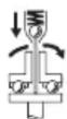
BnHTOBePTNTHe IMAT npeKbCBAu cBeDHHTeN, OTdJIaB 3aBNCIMOCCT OYcTaHOBENH BbpTAA MOpENT, KOITOMoKe Da 6bJe peRyInpaH B NocOeHINaIaNoH. ToI ce 3aJeICTBa, KoRATO 6bJe DOCTIHnat HAcTPOEHN BByTAA Mo
MEHT.
Yka3aHHe:Korato 3axpaHbATEBHTOBepTa c anaNTep 3a HanpeXeHHe, npBo Tp8Ba Da BKNIOUHTe TOKON3PpABTeJI.
3a BkHouBaHe Ha eJKeTPOINCTPymeHTa HaTHcHete NyckoBnI ppeKbCBAu (13) Do ynop.
EJIeKTPoINHCTpyMeHbT Ce H3KJIIOUBA aBTOMaTHUHO, KOraTo 6bJe IOCTHnHaT IpeBbAPteIeHNo HaCTpoEHnT BbptraM MoMeHT.
Pn npexkdeBpeMeHNO OTnysKaHe Ha nycOBnna PpeKbcbu (13) He ce DocTHra npedBapHTeHNo 3aadaHnBbPTaMOMeHT.
Yka3aHna 3a pa60Ta
IpeDn Da H3BbPbATE KaKBInTo N da e DeHocTH no eneKtpOnHcTpymEnta (HaNP. TexNHeCko 6cbNyXba- He, CmHa Ha pa6oTHn HcTpymEn T. H.), KOrato ro TpaHCnpOtnpAte Nn CBxPaHbAte, DEMoHTnpaTe aKymNaTopHata 6ateRn. CbIeCTByBa OnaCHOCT OT Ha paHbAhe pni 3aDeEChBaHe Ha NcKOBn IpeKbcBau No HEBHImaHne.
IocTaBaiTe eNEKtpOnHcTpymeHa rIaBaTa Ha BnHTa/raKaTc mao KOraTo e N3KnUoye. BbptTuaT ce pa60TeH IHCTpyMeHT MoKe Da ce N3MeTHe.
PerynnpaHe Ha BbptTmN Momett (Bx. nG-1)
BbpttMOMENT3aBcNOTpEeBaHrTeHnHOHaTtAHe Ha npjHKHaTa HnpeKcbCBAUHcBeEDHHTe. PpeKcbAuHrCTbeHNHTeCe 3aJeCTBa pni DOCTnHa He 3aDaHeHH BbPTtMMoENTKaKTo ppi BbPteHe HaJACHO, Taka N ppi BbPteHe HAJIBO.
3a hacTroBbAe Ha JKeJAHn BbPTru MMoHt H3NoI3BaYTe CaMO BKIOUeHn BOKOMJIeKTOBkTa HNCTpyMeHt 3a peRyIIPAhe (30).
Ппемстete пьзага (7)Ha eNeEkTpOnHCTpyMeHTaДOKрай Na3aJ.
ANGLE EXACT 2|3|6|7|8|15|17|23|30
BkapaIte IeCTOCTeHEn KJIIOU (31) B pa6oTHnIHcTpymeHT (30) nTO 3aBbPTe6bAHO.
Korato npe3 OTbopa B Koppya ce BnDm MaNka BdIb6HaTHHa (perynipaa 7aib6a (32)) B cbeHNHTeR, BKapaiTe B He NHCTpyMeHTa 3a perynipaHe (30) n ro 3aBbptTe.
ANGLE EXACT 14CF | 22CF | 29CF
Cn3BaTe yka3aHnra Ta KbM 3akynHeHaTa OT BAc PnOcKa BbP TnaTgnaB aHn nonTae Ba7n TbproeU.
3aBbPTaHe IIO NOCOKA Ha YacOBHnKoBaTa CTpeIka BODn Do yBeJIuYBaHa He bBPTaIIIMOMeHT, 3aBbPTaHe O6paTHO Ha YacOBHnKoBaTa CTpeIka -Do HAmJIyBaHe.
I3BaTe HeHCTpyMeHTa 3a peryHpaHe (30).IpeMeCTeTe Ib3raVa (7) OTHOBo HAppe,Ia IpeIpa3nte CbeINHTeJIr O3AmbpcBaHe.
Yka3aHHe: Heo6xOHNMnT BbptIc MmEHT 3aBNCN OT BnDa Ha BnHTOBOTcBeINHeHne Ie ONpeIeNHaJ-TOUHO Upe3 H3np6BaHe Ha npakTnKa. PpOBepTe pO6Ho 3aBnTOTo CbeDInHeHne C DnHAmOMeTpueH KJIou.
PerynpaTe BbptTmN MoMeTcMoB nocouHn Dnapa3OH Ha MoHocTtA, TbK KaTo B pOToHBen CnyaH N3KNUByaUNrT CbeHNHTe He ce 3aDeIcTBA.
06o3haaBaHe Ha HactpoeHn BbptTMMoment
ANGLE EXACT 2 | 3 | 6 | 7 | 8 | 14CF | 15 | 17 |
22CF|23|29CF|30
3a 0603nauabaHe Ha cneuaHNO HAcTpoEH N BbPTaIe MoMeHTN MOKeTe Da 3aMeHIne MapKnPOBbUHn IpbCTeH (17) C TaKbB C Dpyr CbYt.
Hanpimep ako n3non3BaTe qact OT bHTOBeptIte EXACT c BbPTaJMMoMeT4,5NmMOKeTe da hN moCTaBte 3a o603- hauabaHe uepeBHeM MapKnPOBbUHN pBcTeHN.AKO n3non3- Bate dpTu BNHTOBePTIgEXACT 3a dpyrMoHTaxKHeJeHoCTn,PnKoTcE He nO3no3Ba BbPTaJMMoMeH7,5Nm,MOKeTe Da NOCTaBte 3a 06O3NaUaBaHe Ha TO3N BbPTaJMMoMeH TMapKnPOBbUeH NpBcTeH Cdpyr UBT (YepeH,CIN,3eEn HJI KblT).MapKnPOBbUHNTe PpBcTeHN c pa3JIuH eZBtCa npEdHa3naueHc Camo Da cnykat KaTO yLecheHHe 3a MOHTbOpNTe,3a da ce pa3No3HaBa No-JleCHO KaKbB BbPTaJMMoMeHT eYCTaHOBeH Ha cbOTBeTHn ENEKTPOHHCTpymENT.
3a n3BaKaDaHe Ha MapKIpOBbUHnI npbCTeH (17) n3PON3BaIte TbHka OTBepTKa, Wnakla nnDpyr noo6eH nHcTpyMeHT.
BnHaHn 3nOJ3BaIte eNeKTPOINHCTpyMeHTa C nOCTaBeH MapKInPOBbUeH npbCTeH, 3a Da 6bJe 3aUHTeH Kopnyca O T npax H 3AmbpcBaHe.
CBeToDnOdHn HnDnKaTOpN

CbeToNDIO3aCTeNEHTaHa3apeDeHocTHa akymyIaTOPHATA6bTePnA
Ako e Heo6xOIMo 3apeKdaHe Ha akymyata TopHa7 6atepna (11), 3eHnT CBetOnIOdEn
HINKKaTOp (10) 3aNoUBa Da MHa n Ce UyBa 3ByKOB CnHAn. CLeD ToBa Ca Bb3MoXHH OSe caMo 6 Do 8aBnHTBaHna.
Ako CBeToOnIOBbT CBeThe C UepBeHa CBeTInHa, KaIaUTeTbHa 6aTepeHra Te DoCTnRa 3a OSe eJHO 3aBnBaHe /pa3BnBaHe nII enEeKTPoHNCTpyMeHbTe 6bn IpTeTOBaHc. Cne ToBa eNekTPoHNCTpyMeHbTe He MOKe Da 6bDe BKNIOueH IOBEue. BLOKINPOBkata 3a BKNIOuBAHe oCTaBA aKTINBA, DOKaTo aKYMyNaTOPHaTa 6aTepeHRe 6bDe N3BaJeHa OT enEeKTPoHNCTpyMeHtA H Hero He 6bDe NoCTaBEHa HOBA 3apeDeHa aKyMyNaTopHa 6aTepeHra.
Ako pa6oTIne c aAnTep 3a HnpeXeHne, CBeTbAHeto Ha CBToOnIOdNII INIINKaTOp (10) c cepBHeNA CBeTNIHa e yKa-3aHne 3a npTeObapBaHe.
Ako CBToIOHNOHHT HINKATOp (10) Mnra C cepBeHa CBETIINA, eNEKTPOINHCTpyMeHTbTe npeprJN Ie cbc 3aJeCTBaHa3aUHTa cpeu nperepaBaHe. Ppei Da BKJIouHtE OTHOBO eNEKTPOINHCTpyMeHTa, IN3yakaJIte IN3BecTHO BpeMe, IDOKaTOMrAaTa CBTIIHa H3rache.
CbueCTBeHo CbKpAteHo BpeMe 3a pa6Ota Ha eNeKtponHcTpyMeHTa CneI 3apeJxDane Ha akymyNatOpHata 6aTePnnaKa3Ba,ue 6aTePnraTa e H3xa6eHa n Tpr6Ba da 6bJe 3aMeHeHa. N3xBpRnHeTo Ha cTapa Ta akymyNatOpHa 6aTePnra Tpr6Ba da ce H3BbpSs Ch6pa3Ho BaINdHIne pa3npoe6n.

CbeToHnO3aBnBaHe
Ipn doctnrahe Ha npedBapntenH0 yctaHOBeHHN BbptTMMeHT N3KIIIOUBAunr TcbeHNITe ce 3aJeCTBa.CBtOINoDnHr INdkaTop
(9)CBETBa3eIeHo.
Ako npedBapntEnHO yCTaHOBeHnT BbPTtM MmOeHr He 6bJe DOCTnHAT, CBToNDnHnT HnNkAtop (9) CBeTa YepBeHo, n Ce cyBa 3ByKOB cngan. IpouecBt Ha 3abBaHe Tp8Ba da ce NOBtOpn.
3aunTa OT NOBTOpeHne
Korato B npocca Ha 3aBnBaHe n3kHIOvBaIyT CbeHNHTe Ce 3aEeCTBa, eNEKTOpOBNrAteIaTc He 3kHIOuBa. NOBTOHO BKIOUBAHe e Bb3MOxHo eDba CneI INTePBoAOT O, 7 cekyn. Taka ce H6raBnpeHaBnBaHTo Ha Beue 3aterHaTH BnTOBn CbeINHeHn.
IpomraHa Ha N03nuaTa Ha bTNOBaTa 3aBbBaa Ta rnaBa
ANGLE EXACT 2|3|6|7|8|15|17|23|30
MoxTe Da nocTaBnTe bTnOBaTa 3aBnBaua rnaBa (3) B eHa ot o6o ocem no3uyn.
3axbaheTe eNeKtpOnHCTpyMeHTa c raeuehen KIOU (6) 3a NOBbpxHOCTIte HaΦlaHeua (5)Ha bTNOBaTa rnaBa.
HnKora He 3aTaraTe eNeKtpOnHcTpymeNTa KbM nIOCKoCTHTe Ha Kopnyca.
CraeHnKJIOU (4) pa3BnIte XOJIeHpOBA tga KAIka, KaTOЯ 3aXBaHeTe 3a NOBbpxHOCTInTe (19). 3aBbPTeTe bTNOBaTa 3aBnBaUa TnBa (3) Na CTbNkN OT 45^ Do JKeNaHaTa N03uNIA CraeHnKJIOU (4) OTHOBo 3aTeHETe XOJIeHpOBA tga KAIka, KATOЯ 3aXBaHeTe 3a NOBbpxHOCTInTe (19).
Service scule electric
Strada Horia Macelariu Nr. 30-34, sector 1
013937 Bucuresti, Romania
TeN.: +359(0)700 13667 (Блгарский)
a c: + 40212331313
Email: BoschServiceCenterBG@ro.bosch.com
www.bosch-pt.com/bg/bg/
BpaKyBaHe

EleKtpOnHcTpyMeHTne,akymyTaOpHnTe 6a- Tepnn n DOnbInHTeHNHe npncnocobJeHH Tpa6Ba da 6bDat npedeBaHn 3a onoN3OTBopra PpKaunTe Ce B TEx CypOBHH.
BaHe Ha CbDpbJxAaIITCe B TIX CyPOBHNH.

He n3XbBpIaIe eIeKTpOIHcTpMyeHTn I aKyMynatopHn IIN o6NkHOBeH bAtePn Ipn 6bTobHTe OTnaDbIu!
Cama 3a ctpaHH ot EC:
CbINaCHO eBpOneiCKa IInpeKTHBa 2012/19/EC eIeKTPoPyPeDnTe, KOHTo He MOrAT da Ce IOn3Bat NObYe, a CbIpaNcHO eBpOneiCKa IInpeKTHBa 2006/66/EO NOBpeHEn HnHn H3xa-6BeHN oBnKnHOBeHn HnN akymyNatOpHn 6aTePnN Tpr6Ba Da ce Cb6HpA n PpeDaBa 3a OOn3OTBopRJaBeHa H cBdpbXuaNITe Ce B TxA CypOBHH.
AkymynaTOPHn HnO6nKHOBeHn 6aTePHN:
Ni-Cd: HNKEL-KaDMN
BHHaHHe: Te3n aKymyIaTOPH 6aTePnN cBbJbPkaT KaI MIn, KOTo E CnHIO OTOpOBeH TeXbK MeTaI.
NiMH: HnKeI-MetaJIxHIDpiD
MaKeDoHcKn
БeЗбedingн Наомени
OnuTn npedynpeyBaHa 3a 6e36eHocT 3a eJeKtpuHn anatn
PNEy- PNDYBAHe
IpounTajre rH cHTe 6e36eHocnnpedynpeyBaHa, Hnyctpaunn CneuФнkaun npnloxehn co
Oboj enektpuhen anat. HenpndpxyBaHeto Do cnte ynata StbAp npINOxehn pOOny MoKe Da IOBepe Do cTpyeh ydap, noKap N/nnI TeShKn NobpeiN.
3auybajte r6e36ednchntpeynpdeyBaHa uynaTCTBa 3a KopncTebe M 3a BO NdHHa.
POnmOt ,eNeKtpuH e anat" Bo 6e36eHocnHTe npEynpeDyBaHa ce OndecyBa Ha eNeKtpuHn anapatn wTo Kopnctat cTpya (Ka6eIcKn) nH anapatn wTo Kopnctat 6aTeprn (akymylatopcKn).
Be36eHnOcHa pa6oTHHot npocstop
Pa6oTHNOT npocstop oopjyBaJTe ro uHCTn do6po oCBetne. IpeonHn nn TemHn npoctopn MoKe da DoBeDaT Do HecpeKa.
He pa6oTeTe co eNeKtpnHHTe anaTH BO EKcIIO3HBHa OKOINHa, KaKO Ha npHMep, BO npHCyCTBO Ha 3anaINBn TeuHOCTH, racOBH nHn npaINHa. EneKtpnHHTe aIaN Co3daBaat NCKPN KOnlTO MoKeJa ja 3anapat npaINHaTa nnr racOBHTe.
Држete Гдеца и псунтнente поалени дodeka pa60ntte co eeneKtpuehen anat. HeBHMaHHeTo Moxke da npdei3BnKa da n3rHy6nte KOHTpOna.
EneKtpnua 6e36eHnoct
PnPKnyokuToHa eNeKtpuHnO t ana mopa da odroBapa Ha npKnyuHncaTa. HNKorau He ro meHyBaJte npKnyuOkt. He KopncHTe npKnyuHn aadTepn co 3a3emjeHnTe eNeKtpuHn aIaNTH. Hen3MeHeNTe npKnyUoOni n COoDBeHTnTe pPKnyuHn zu Ro HAmaLyBaat pn3IKOT oD CTpyeh ydap.
N36erhybaje Teneceh KOHTaKT co 3a3emjeHH NOBpuHH, KaKo Ha npHMeR, UeBKN, paJnaTOpH, MeTALHN Launu N NaUNnHn. IocToN 3roJeMeH pN3NK Od cTpyeh ydap aKO BaUeTo TeNo e 3a3emJeHO.
He n3noxybajte eneKtpnHHTe aatn Ha doxk nn BnaXnn yCNOBn. Ako Bne3e BOda BO eneKtpnHNTaT, Ke ce 3rOlenmuN3NKOT od cTpyeH yap.
He noctanybajte hecooDbetno co ka6enot. Hnkorau He ro Kopnctete Ka6enot 3a Hocebe, Blevebe nn NcknyBaBe o ctpyja ha enektpnuHnot anat. Ka6enot yubaje ro npdaeneky oJ oran, MaCNo, octpn NBnH nIOBnHN DeOBn. OwteteHH nnn 3aJIneTKaHn Ka6nI ro 3rOJeMyBaAT pN3IKOT oD ctpyeH ynap.
Pn pa6oTa co eNeKtpuH eAaHa OTbOpeHo, KopHeTe IpoDOnJxH KAben CoOdBteH 3a HAdBopeHna yNoTpe6a. KopHeTeHO Ha Ka6eN COoDBeHc 3a HAdBopeHna yNoTpe6a ro HAmanyBa pInIKOT Oi CTpyeH yIap.
Ako Mopa da pa6oTne co eNeKtpnueH anat Ha BnaJxHo MeCTO, KopncTe 3aHTHeN ypeD 3a NfpepeHunJaHa cTpyja (RCD). KopncTeBeTo Ha RCD ro HaMaJyBa pN3NKOT od cTpyeH yap.
JIuHa 6e36eHnoCT
Bndete BHHMaTeHNH, BHHMaBajte kako pa60nte npa60Te p3zymHo co eJektpnueh anat. He KopHCTe eJektpnueh anat aKO cTe yMOPHN HIN NOd JejCTBO Ha Iporn, anKoXoN IHN NekOB. EDeH MOMENT Ha HeBHHMaHne IdoKeKa pa60nte co eJektpnueHte anat MOpke Da IIOBeDe Do cepno3Ha IInuHa NOBpeJa.
KopncTe TnUHa 3aHTHb Onpema.Cekorau Hocete 3aHTHa 3aOu.3aHTTHaTOnPema,KaKo Ha np.. Maca 3a npaunHa,6e36eHocn YeBIn KOuTo He ce NIm3raat,JIeMmNn 3aHTTa 3a yUn,KOuTO Ce KopnCTaT 3a COOdBETHN yCNO,B,Ke DoBedaTdo HAmaIyBaHe Ha NluyHn IOBpeDn.
Cnpuehe HenaMepeo akTbHpaHe. IpOBepeTe daHn npKeHHyBaOT e NcKlyuEN pPe Da rO BkLyuHTe BO ctpya H/nn Co cetOT Ha 6aTePHN, pPe Da rO 3emTe Hn HocHTe aHaT. HocHe Ha eNEKTprHNTe aHaTH co nPpCTOT POn3UHOHNpaH Na npKeHHyBaOT Hn BKLyUByBaBe BO cTpya Ha eNEKTprHNTe aHaTH uJiTo npKeHHyBaOT e BkLyuEN, MOKe Da npEIN3BnKa HecepKa.
OTcpanHe T KaKOB 6nlo Knyu 3a peryInpaHe nnn
fpaunCkN Knyu nped da ro BknyuHte eneKtpnHnot
anat. FpaunCkN Knyu nn H Knyu npikaueh 3a
poTnpaKnOt DeI Ha eNeKtpnHnot aIaT Moke da doBeJe
do InuHa NOBpeJa.
He rH npeukopybajte orpanuhybahta. Noctojano odpxybjte cooDBetna noox6ha pamhoteka. Oba OBO3MOxkyBa IIO6pa KOHTPOna Ha eJeKTPnUHOT aIAT BO HeIpeBnINHBnCITyaunn.
O6neueTe ce cooDbetHo. He hocete shpoka obNeka n haKHT. Kocata n anHtata Tpe6a da 6nDat noJanaEky od noDBNxHnTe DeNoBN. Iupokata o6Neka, hAKNTOT NIN DOJIrata KOca MoKe da ce 3aKaayat 3a noDBNxHnTe DeNoBN.
Ako ce Koprncstat nobp3aHn ypeHn 3a Baedebe npaunHa n co6upaBe npdeMeTH, npoBepTe daHn ce npaBnHO NOBp3aHn KOpNCteH. Co6upaHTo npaUnHa MOKe Da Tn HaMaHn ONaCHocTHe npeDn3BnKaHn Od Hea.
He do3bonybajte hckyctb0t cekhato co yecta ynoIpe6a ha anatne da Be hapnabn cnokoJn n da rHnrhoprate 6e36ednochnte pinnu nn pn HNBHTO kOpncTebe. HeBnmatelno DnbKxeBe moKe da npedn3Bnka cepno3Ha nobpeDa BO den od cekynda.
Ynotpe6a n cyBaBe h a eNeKtpuHnte anatn
He ro npeonTobayBajte enektpnHnot anat. KopncTeTe cooDBeTe H eektpnueH anat 3a HameHaTa. Co cooDbetHnot eektpnuH anat noio6po, no6e36edno n no6p30 ke ja h3BpuHtpe pa6oTata 3a Koja e HameHET.
He Kophcte eeneKtpnueh anat aKO He moKeTe da ro BknyuHTe H NCKlyuHTe co NOMOHa IpeKNHyBaOT. Ceko eeneKtpnuH anat KojUTo He MoKe Da ce KOHTpOInpa Co IpeKNHyBaOT e OnaceH mOpa Da ce nonpaBn.
McknyeTe ro eNeKtpnHnot anat od ctpya n/nnn 3BaTeTe ro cetot Ha 6aTeHH, aKO ce BaHN, nped da npaBHe T HeKaBn PpHnaIroDyBaHa, MeHyBaTe DOnONHTenHa ONpeMa Hnn Ro CkNaInpate eNeKtpnHnot anat. Co OBne IpeBeHTNBn 6e36eHNoCHm MepKn Ce HamaNyBa pN3IKOT od cnuyajHo BKNyUyBaHe Ha eNeKtpnHnot anat.
Uybajte rne eneKtpnHnTe aIaN noIaNeky oIdofoHa nIeca I He I03BOnyBaJte INuCaTa KON He paKyBaIe co eNekTPnHnO t anat HIn He ce 3aNo3HaEH Co OBAynatCTBO da pa6oTat co hctnOT. EneKtpnHnTe aIaNtCe onacNI BO paueTe Ha Heo6yuHn KopncnIi.
OdpKyBaBe Ha eNeKtpnHn anaTn HdoonHnTeHa onpema. IpoBepete ro npamHyBaBeTo Hn npuCByBaBe Ha noDBXHNte DeNoBn, cnojot Ha deNoBHTe n CNTe dpyTN yCNOBn wTO MoKe HeaTHBHO da Bnjaat Bp3 fynkUHOHPaBeTo Ha eNeKtpnHnOT anat. Ako e oWteten, odHeceTe ro eNeKtpnHnOT anat Ha nonpaBkA nped Da Ro KopHCTne. Mhory HecepKeN ce npedIN3BnKaHn 3apaDn HecooDbTeHO OdpKyBaBe Ha eNeKtpnHnTe aanaTn.
Octpete H uHCTe Tn anaTHe 3a ceYebe. CooBcHo OdpJyBaHInTe NBUuHa aIaNtHe 3a ceYebe nOMaIKy Ce BNTKaat I NOleCHO CE KOHTpOINpaaT.
EneKtpnHHTaIaT,doONHHTeHaTaOnpeMa, DeIOBHTe HdP.,KOpHCTeTe rN BO cOrnaCHOCT CO OBA yNaTCTBO,BHMAbajTe Ha pa6oTHte YcNoBn pa6oTata Koja ja BpHnte. KopHCTeHeto Ha eNEKtpnHHTo aIaT 3a dpyTu HAMeHN MoKe Da IDoBeDe Do ONaCHN CNTyaUaUN.
PaKHTe N NOBpHINHTE 3a DpKHe ODPxByaJIte rN cyBn, HcTn H Hen3MaCTeHN. PaKHTe N NOBpHINHTE 3a DpKHe ITO CE IIN3raat He OBO3MOyBaAT 6e36eJHO paKyBaHe I KOHTpOla Ha anaTOT BO HENpeBnIINBn CNTyaUIN.
Ynotpe6a H cyBaHe Ha 6aTePncKn anat
Ponhe ja 6aTeprjata cmo co nHaH habeDen o npOn3B0DnteIOT. POnHau KoJwTo e COoDBteH 3a eEHN TnCt Ha 6aTeprn MoKe Da npEni3BnKa ONaCHOCT O npKap aKO CE KOpNCTn 3a Dpyr Cet Ha 6aTeprn.
EneKtpnHHTe anaTH KopHeTe Tc moCo CneuJaanHO HameHEn CeTOBn Ha 6aTePN. KopHeTeBeTo Ha npTu n ceTOBn Ha 6aTePN MoKe da npEdn3BnKa ONaCHoCT Ond NOBpeDa HIN NOKap.
Kora he ro Kopnctte ceTOT ha 6aTePm, yBaJte ro noJaIeKy od npYr MeTALH npeMeTH, KaKo Ha np., cNojyBaIKN, MOHeTH, KlyueBn, WajKN, 3aBPtKN nn npYr NoMaIIh MeTALH npeMeTH wTO MoKe da npEn3BnKaat Cnoj OD eEN Do dpyr H3BOp. KpaToK cNoj ha 6aTePnckTe n3BOpN moKe da npEn3BnKa n3ropeHnNi NiPi noJap.
Пов Ненидени Okонocн, Teчесу може доступе od 6atepjuata; n36erhybajte kohtak. Ппс сныаehdonnp, n3mijte ce co mna3 boda. Ako Teuchostа Bne3e BO OOHTe, no6apajte doonHntenha MeHHNCHKa pOMoi. Teuoc hceueHa od 6atepnjata Moche da PpeDn3Bnka npitauziJa nII INI3ropeHnii.
He yonotpe6ybajte cet ha 6atepnn nn anat wto e oHTeTeHnn H3MeHET. OHTeTeHn nn H3MeHETn 6atepnn moke da pearupaat HenpeBnDnBO n da npedn3BnKaat noxap, ekcnno3na nn onacHOCT od NOBpea.
He ro n3noxybajte ceTOT ha 6atepnn nn anatot Ha oran nn BncoKa tempepatya. N3noxyBaHeto Ha oran nn Ha TeMpepatya Nobcoka oJ 130^ MoKe da npedn3Bnka ekcnno3na.
CneTe Tn CNTe yNaTcBA 3a nonHebe H He ro
nonHeTe cTeTo Ha 6aTePnHnn anAtoh NaBOp od
TempePaTyPhNt ONcer HabeEn BO yNaTcTBata.
HenpaBnHTo nOJIHeBe HnHa TMpePaTypa HAdBop Od
HaBeEHnOT ONcer MoKe da ja oWTeTu 6aTePnJaTa N da ja
3rOleMn OnaCHOCTa OD NOxap.
CepBncpaBe
EneKtpnHnot anat cepBnchpajre ro kaj KBaINHcKyBaHO nIe KOe KOpHCTn cAmo HHeTHNuHpe3epBHN dIeOBN. Co Oba ce OBO3MOxBya 6e36eHNO odpxyBaHb e ha eneKtpnHnot aIaT.
HnkoraHne nonpaBajte owtetehn cetobn Ha 6aTeHH. IoppaKaTaHa cetobn Ha 6aTeHH Tpe6aJa ja BpuN caMo npOn3BODInTeIOT NIN OBnacteH cepBnC.
Be36eHocn HanoMeHN 3a OdBpTyBaun
Држete ro ekeptpnuHnot anat 3a n3oJnpaHata
noBpUHa doKeKa ceyeTe, 3a npuBpcTyBaOT da He
doJe BO KOHTAKT co ckPHeHa KMuA. Ako
npuBpcTyBaHTe DoJaT BO DoINpco ,KMuA pOn Ha NaOH",
Mоже д Ги ИЗLOЖAT MetalHITe DeNoBn Ha ekeTpnuHNot
anat ,ПОД HANOH" I OpeApToPOT може д доби стpyeh
ynap.
Kopnctete cooBteHn ypeHn 3a npe6apyBaHe, 3a da rH npohajTe cckpneHnte enektpnuHn Ka6n Hn KOHCynTpajTe ce co NOKANHOT npetnpjathe 3a cHa6dyBaHe co enektpnuHa eHeprJa. KoHTAKTOT co eNEkTPnuHn Ka6n MoKe Da DOBeDe Do NOkap i CTpye H ynap.OsTeTyBaHTo Ha racoBODoT MOKe Da DOBeDe Do
ekCIIIO3nJa.HaBJIeYBaHbETo BO BOIOBOHN ueBKN npEni3BNKyBa OwTeTyBaHe.
Ubpcto dpxkete ro eektpnHnoT anapat. Pn 3aucpcTyBaHe n ODbpyBaHe Ha npapobMOKe da HacTaHaT KpaTkoTpajHN BVCOKn peaKTbHN MOpENTN.
3aucpcte ro napyeTo wto ce 6bpa60tyBa. IOKoKy ro 3aucpcntte co ypeD 3a3aTeHyBaHe HIN MeHReMe, ToraawnapyeTo wto ce 6bpa60tyBa ce dpxN noocpcto otKoKky co BaWata paka.
Nouekajte dokeka enektpnHHOT anat cocema He npeknhe co pa6ota, nped da ro trpHeTe hactpana. Anatot ITO ce BMETHyBa MOKe Da ce bloKnpa n da DoBeDe Io ryebe KOHTpONa Hnd ypeDoT.
PnOwTeTyBaBe HHe npOnHcHa yNtpe6a Ha 6Batepnjata MoKe Ja H3ne3e Napea. Batepnjata MoKe Da ce 3aapanH nn da ekcnlonpura. BheceTc CBex BOzdyx HdoKoJky HMa NobpeHn OndecTe rHa nekap. Papeata MoKe Da rH NaPa3HN DmHInte NaTHTA.
He ja otBopajte 6atepnjata. NocToH onaChoc T oKpaTOK cnoj.
Batepnjata moxe da ce owtte n od octpnte npedmetn KaKo Ha np. KInHn HnO dBpyBaHn Co HnBopeWBOHnJaHne.MoXe da doJde IO BnatpeWeH KpaTOK cnoj h Batepnjata moxE da ce 3aapani, da npHTn qad, da ekcnlonpa Hn da ce nperepee.
KopncTe ja 6aTepeHjata camo BO npOn3B0nO npOn3BOOnTeNoT. Camo Ha ToJ haun6aTepeHjata Ke ce 3aUHTN OJ OnaCHO pneontOBapyBaHe.

3awtte ja 6atepniata od toponnHa,Ha np.
ODIOnTropajHO n3NoxyBaBe Ha COHcEBn
3paU,Orah,HeNCTOTHN,BOa H Bnra.
Hnaky,poctOn onacHocT od ekcnlo3nja n
KpaTOK cnoj.
Дokonky ce 6LOKnpa anatot wTo ce BMeTHyBa, BeHnau ncknyute ro eNEKTPNHnot anatot. BnTe npETNa3INBn CO BHCOKNte peAKCNUCKN MOMHTN, wTO moKe da npEHN3BnKaAT nobpaTeH yap. AnaTOT wTo ce BMeTHyBa ce 6LOKnpa, aKO eNEKTPNHnot anatce npeontobapn nInCe hAban KOn DeIOT wTo ce 06pa6OtuBa.
PNEy-PNEYBAHbE
IpaBtTa HTo HacTaHbYa npn 1mmprnahe,ceYebe,6pycebe, dYnueBe n CmUHN DejHoCTM MoKe
Ja HMa KaHceporeHo, TepaToReHO Hm MyTareHo DejCTBO. Hekon OJ OBHe MaTePN COIpXaHN BO ppaTc Ce: OLOBO BO 60n I NaKOBu 7TO COIpXaT OLOBO; KpIcTaJeH CINIIuYM BO cIgTN, ZeMeHT N dpyrN SInapCKn pa6Otn; apcen H xpomat BO XemNk TpeTnpaHO dpBO. P3IKoT Od 3a6OlyBaBe 3aBNCn OD ToA KOIky CheTo CTe N3IOKeHN Ha OBne CyIcTaNz. 3a Da ja HamaJIte OnaChocTa, Tpe6a Da pa6OTNe camo BO Do6po npOBeTpEn IpocToPn Co COoDBeTHa 3aWtNTHa ONpema (Ha np. co CneunJalHO KOHcTpUpaHn UpeDN 3a 3aWtNTa npri DnIseHbe, KOI r HfIITpPaAT n HajcHTNte YecTNUkpA).
N36erHyBaJte cnyajno BknyuBaHe. OcnrypeTe ce deKa npeknHyBaOT 3a BknyuBaHe/ncknyuBaHe e BO ncknyeHa no3nju, nped Da CTabnte 6atepna.
HocheTo Ha eneKtpnHiNOT aIat co BaAinot npct Ha npeKInHyBaVOT 3a BkLnyuBaHe/ncKlyuYBaHe nn CTabaHe Ha batepijata BO BkLyuH e eneKtpnH e anat MOKe da doBeE do HeceKeH cnyuj.
Kophtete camo hcnpabHn, Hen3a6eHH anatn 3a BMeTHyBaBe. DepekTHHTe aIaNt 3a BMeTHyBaBe MOXe Ha np. Da ce cKpwaT n da IOBeJat Do NOBpeHn MaTepnjahn HtETN.
PnCtBaHbETO Ha aIaNOT 3a BmETHyBaHe, BHMMabajTe Ha ToA ToJ da IeXn CBpCTo BO npHpaTOT 3a aNAT. JOKONKY aIaNOT 3a BMeTHyBaHe He e CBpCTO IOBp3AH CO pHpaTOT Ha aIaN, MoKe Da ce Ola6aBn I da Ce cIyUd He MoKe Da CE KOHTPOINPA.
Бидente петпалнвпprn 3aВpTyBaHe HaДолгн 3aBpTKN,биdeжпocToN onaChOCT OДИЗHyBaBe,BO 3aBnCHOCt OДиOT Ha 3aBpTkAToH KOpHcTeHNOT aIAT 3aBMETHyBaHe.ЧecToNaТ,ДОЛгпTe 3aBpTKN HeМоже Да ceКOHрОпраat TOnkYdo6po ИпocToN onaChOCT Da ce CIn3HATпprn 3aBpTyBaBeTo Ида ce nobpeДITE.
BHMMaBajTe Ha NoctabeHnOT npaBeu Ha BpTeHe, nped Da ro BKnyuHTe eNEKtpnHnOT anat. JOKoNky, Ha npMep, cakTe Da OdBpTIne 3aBpTKa, a npaBeUOT Ha BpTeHe e NocTaBeH 3a 3aBpTbBaHbe Ha 3aBpTKaTa, Moxe Da DoJne DO CINHO HeKOHTpoIpaHO DmXkeHe Ha eNEKtpnHnOT anAT.
He ro kopncTeTe eneKtpnHnot anat kaKo dynuHaKa.
EeKeTpnuHnte aIaNco eHa cNojka 3a nckLyuBaHe He ce nOroHn 3a dynueHe. CnojkaTMOke aBtOMaTcKn I 6e3 npdeynpeyBaHe da ce nckLyuN.
Опнс на пронзвороти перформансichte

Ipoountajte rH cHTe 6e36ednoCHn HAnomeHH
HvataCTBa. IpeKHTe HaCTaHaTn KaKO
pe3yIytat od HnepnDpKxyBaHbe do
6e36eHochnite HAnOMeHN yNATCTBA MoKeJa npedn3BnKaAteJeKtpuyeH yap,NoXap N/nn
TeuKIOBpeiN.
BHHMaBaJTe Ha cIINKHe BO npeHnOT dEe Ha yNaTcTBOTo 3a KOpNCteHe.
YnOTope6a co cooDbetHa HameHa
ANGLE EXACT 2|3|6|7|8|15|17|23|30
EneKtpnHnoT aIaTe HaMeHeT 3a 3aBpTyBaBe n OIa6abByBaHe Ha 3aBpTKn, HABpTKn I npTu CBp3Hn eIeMeHTu CO HAbOJ BO DaJeHIne TpaHnU Na DImeH3Nn MOKHOCT.
EneKtpnHnO anat He nOroJeH da ce KopnCTn KaKO dynuAJa; 3a Da n36berHeTe NnuHn NobpeDi n MaTePnJaHn WtETn, HNKorAaH Te Tpe6a Da ro KopnCTte eNeKtpnHnO anat Co nCKnyHa cnojKa 3a DnyueHe.
ANGLE EXACT 14CF | 22CF | 29CF
EneKtpnHnot anat npadn herOBnT 6aBEN neb Te k HameHet 3a pa6ota co OTbOpen nIOchat nOrOH co rohet
3anueHn. Toj e noroDhen 3a 3aBpTyBaHa Ha MeCTa KaTe HMa npCTan cAmo OJ eHaTa CTpaHa, Ha np. Ha ZeBKOBoNi. He e noroDhen 3a oNaabYBaHe Ha 3aBpTKn.
EneKtpnHnO anat He nOroJeHa ce KOpNCTn KaKO dynuAJa; 3a Da n36berHeTe NmHn Nobpei n MaTePnJaHn WtETn, HNKoRaIe H Tpe6a Da rO KoNCTnTe eNeKtpnHnOT aJAT CO hCKnyHa cNojKa 3a DyUpeHe.
Hnyctpaunja ha KOMnOHeHTN
HymepnpaheTo Ha cInKHTe CO KOMNoHeHTe ce OndecyBa Ha npika30 Ha eNEkTpnuHnot aalat Ha IgraФuKaTc CTpaHnua.
(1) A NaT 3a BMeTHyBaHBe (Ha Ipi. HABpTKa 3a 3aBpTyBaHBe)
(2) Pnudat Ha aIaTOT
(3) AroIHa rnaBa Ha oDvBpyBaOt
(4) Bnlyukact kny co shnpna 27 mm
(5) Повшина на Клuyот на прирабницата на arолнatable Гльва
(6) BnIyIkaCT Kny co Iu npHa 22 mm
(7) IиЗrau 3a npTeXOdEN n36Op Ha BpTeKeH MOMENT
(8) Kyka 3a 3akaayBahe
(9) LED-πρικα3 Ha 3aBpTyBaHbTe Ho cNojHnUte
(10) LED-πρικα3 ha coctoj6aTa ha ha nονηteocT ha 6aTeprjata
(11) BaTepeJa co APT- npKJyuEn KOHTaKT
(12) Konue 3a oTbopahe Ha 6aTepujata
(13) Ппекинунвач за вклuyуВа Howe/NckluyuВа Howe
(14)П配电инвачзMeHyBaHeHa npaBeUOT Ha BpTeHb
(15) OTBOPn 3a npuBpctyBaHb e Ha npjkaOTo 3a 3aKaUyBaHe
(16) LED-Dpkau
(17) Постен за обеленива bene
(18) Pa60THa CBETINka
(19)ПовшинаHaКлуOTанпpeknlonнataHaВrtka
(20) KoHTpa-HaBpTka
(21)Поннан.
(22) CtpyuH npnKnyuok
(23) 3eJIeHn LED-ppnKa3n Ha noIHaOH
(24) LüPbeHn LED-ppnKa3n Ha noJIhaOH
(25)ПриклuyенkoнковTopаструенадантерна4EXACT
(26) D-Sub-npknkyok
(27) 3aBPTkn Ha D-Sub-npknnyok
(28) CtpyuH aadanTep
(29)Брзозаггувактлары.
(30) Ala tə nOeCyBaHbe
(31) Knyu co BnATpeuHa wecTaorHa rnaBa
(32)Плочka за поедуванe
(33) Cnrgyphocen npcten
(34) Wypnlna BO TeNoTo Ha KyKnIeTeO
LED- npnka3nte He cBeTaT
| Стугунnot рпклuyок на полнаот не e (прави乳业) ВмETHAT | Стугунnot рпклuyок (ценихо) e ВмETHAT BO прклuyнцараза |
| Прinksунцараза, стугунnot Кабел лим понаот се дебеekteн | Проберете го стугунnot Нанон, a понаот octabete го на пrobерка BO асторизраha сервиса сныжба за Bosch- endektpruchни алати |
He e Bo3MOxH npOec Ha nonHeBe
| Tempepatyata Ha | Приларове ja |
| 6ateprjata He e Bo | Tempepatyata Ha |
| ДоЗвoleнITE грани | 6ateprjata co Ладеные ипс сторуbaль bo Д氧звoleнITE грани Na Tempepatура |
PnpuHa Nomou
PerynaTop Ha HanoH (Bnuu cInka B)
ANGLE EXACT 2|3|6|7|8|14CF|15|17|
22CF|23|29CF|30
Hanomeha:Индустпскпге 6атериcke n arolnno OДВртувачаJIТернаТИВно можда се корист и co perулатог на HanOH.
InyctpnpaHnO Tcpye npknkyok moKe da ce pa3nkyBa oJ npknkyokot 3a BaHnOT eNeKtpuH e anat.
BHMmAbajte,perynatopotHaHanoH Mopa da e cooDbTeH Ha ctpyjHataMpexa BO Bauata 3emja.
OcbenperyanaTopoHaHano4EXACTncooDbetHnoT ctpyeKa6e,notpe6eBn e n ctpye anaTep co nctnoT HOMHaJen HanoH kaKoN Baunot OdBpTyBa.
Hanohot ha peryanaTopot ha hanoi (LED-npknka3) Mopa da 6nde BO cornachoct co hanoiHot Ha oDBptyBaOT. PeryanaTopot Ha hanoi NCKluyuBO e Hamehet 3a INndctprncnte 6atepcnskO dBptyBaun O Bosch od cepintte EXACT, ANGLE EXACT n BT-EXACT co hanoi Nomefy 9,6 V n 14,4 V. Nhaky nocctOn onacchoT od nojkap n ekcnnoiJa.
PpHKnyuok Ha HanojyBaHbeto co eheprnja
Hanomeha:Be monime BHHmAbajte Ha Toa IeKa npin Hcnpokata He e BMeTHata HHTy 6aTepnja HHTy cTpyeh aadantep BO eJektpnHnot anat.
He r nu yubajte 6aTepeHnTe Bo 6aTepeNcKu ypeI.
BaTePnIte Tpaat noDIOIro n IOIO6po ce noHAT,doKoNky ce yBaat OdienHO. IOnIroTo yBaHe, cenocho hanoHete ja 6aTePnJaTnped ynoTpEbaTa.
PonHeBa 6aTepnjata
HanohetajaepcabaheTOeNEKTPnHno
aIATBOoOdbetENONHa.TouHHOTOnHCnPOueCOT Ha
nonHeBoNpEJHTeToBOyNaTCTB0To3aYnOTpe6aHa
nonHaOTHNanomeHteBOOBAynatCTBO(BND,IPoecHa
nonHee",CTpaHnca247).
BaTePnJaTa e onpeMeHa cO NTC-koHTpOna Ha TempepaTypaTa, ITo DOzBOJyBa IOnHeJe cMo BO rpaHnIc Ha TempepaTpya nomery 0^ (+32^) n 45^ (+113^) . Co Toa ce NoCTnHyBa DoIr Pok Ha yNoTppeBa Ha baTePnJa. Co npaBnHa yNoTppeBa bTePnJa moKe da Ce hAnoHn Do 3000 naTH.
Hobata 6atepnja nll 6atepnjata wTo He y npotpe6ybaHa noDolnro Bpeme, nolhata jaunha jaocntnhyBa no OKony 5 cnknycna nolnehe n ppa3nehe. 6atepnite tpe6a da ce donlonhat,dyprn otkaO LED-npika30 ,HaonHeTOCT ha 6atepnjata " Ha eneKtpuHnot anat CBTe ncpBeNo.
CtBaHe H BaHe He Ha 6aTepnjata
PnITNCHTe ro npKeHbAyOT 3a MeHyBaHe Ha npaBeoT ha BpTeHe (14) BO cpeHa no3uJa. Oba ro fKnCnpa npKeHbAyOT 3a BKluyBaHe/INckLyBuHe (13) BO no3uJa IckLyuEHO, CO lTO ce cnpeyBa HeBHMaTeHOTO BKluyBaHe HA eNEKTPNHNOT aAaT.
BmETHe ja haonHeta Ta 6aTepnja (11) Bo npkaTa Ha eneKtpnHnot anat.
BnMaBaJte Ha Toa, 6aTePnJaTa Da ja cTaNBe BO npaBnHa
no3nJa, H KOnuHbTa 3a OTKnyBuHbe (12) Da ce
pnttCHat Ha dPzkata Ha eJeKtpnHnot aanat.
He ynotpe6ybaje cna npn ctaBahe/Baede He 6aTepnjata. BaTePnn CO APT-KoHTaKT 3a npKluyBahe (Akku Pack Top) ce KOHcTpypanHa ToJ Naun, ITo MoKeJa Ce cTaBaT CaMo BO pRaBnHa Po3NiJa Bo eNeKtpnHnO aJat Nn POnHa.
3a da ja n3BaJnte 6aTeprjata (11) npNTncHe naDbTe CTpaHn Ha KOnuHbTa 3a otKluyBaHbe (12) n3BneJe ja 6aTeprjata HADONY od npShkata.
CtabaBe N BaedeBe Ha cTpyjHnO T aanTep (BvDn CInka C)
ANGLE EXACT2|3|6|7|8|14CF|15|17|
22CF|23|29CF|30
OdbepeTe ro cooDbetHnOT cTpyeH aanTpE 3a HOMHaJIeH NaHOH Ha BaIINOT eNEKtpuH eAaT.
CtpyjHnOt aJaanTep ce pa3aNkUyBa BO 3aBnCHoCT OJ HanoHOT cnopei 6oJATA HA KyKniSTeTo HA D-Sub-npHKnyOkOT (26). KyKniSTeTo Ha D-Sub-npHKnyOkOT 3a 9,6-V-haNoE Bo CBETNO cHa 6oJa n 3a 14,4-V-haNo HO zPna 6oJa.
KyuHHToHa aanTepot (28) cme da ce moHTnpa Hn dmoHTnpa caMo DOKOkny perynatopOT Ha Hanoe NCKnyen Hn BO pNKnUOK (26) n3BaDen opeRyNaTOpOT Ha HAnOH BO HndcTpncKnte 6aTepeNcKOn OdBpTyBaHn.
PnITNCHErTOIpeKHyBaUOT3aMeHyBaHbHa npaBeOHT HaBPTeHe (14) BO CpeHaIO3NzJa. OBa rOfHKcnpaIpeKHyBaUOT 3a BKluyBaHb/E/IKLnyBaHbE (13) BOIO3NzJa IckLyuEHO, CO lTo ce cnpueyBa HeBHmAtenHOTOBkLyuBaHb Ha eJELKTPNHNOt aAaT.
BMeHTeTo KkyKnIeTeTo 3a aadantepot (28) Bo DpWkaTa Ha eNeKTpnHnot anat. BHNMaBaJte Ha toa, kyKnIeTTo 3a aadantepoT da ro CTaBnte BO npaBnHa nO3nju, IN KOuHbTa 3a OTKnyBaHe (12) Da ce npITncHa T ha dPshKaTa Ha eNEKTpnHnot anat.
Itoa ctabeTo IpnKnyuKOT (26) To oJroBapa Ha CTpyjHnO T aanTep Ha BaShnTo eNeKtpoHcKn aanT Bo npKnyuHnTo KOHeKTop (25). PnpucbpTeTo pNknyuKOT (26) BO pNknyuHnTo KOHeKTop (25), co 3aTeRaBe Ha dBeTe 3aBPTK (27) co paka.
3a da ro n3BaJnte cTpyjHnOT aanTep, OdBpTeTe rN DBeTe 3aBPTKn (27) od npKnIyOkOT (26) Ha NcKnyeHnOT
peryaTop Ha HanoH nI3BLeueTe ro pInKnyuKOT oD pInKnyuHnO KOHeKToT (25).
Ha Kpaj, npnTncHe Ta DBeTe CtpaHn Ha KOnuHbTa 3a OTKnyBaHe (12) n H3BneTe ro KyKmUTeTo Ha aJaantepot (28) od npkata Ha eneKtpuHnOt aJat.
3aMeHa Ha anaTOT Kaj 3aBptka co 6p3o3aterHyBaqukata rnaBa (BnDn cInka D)
PnCtBaBbetoHa aIaNOT3aBMETHyBaHBe, BHMMabajTe Ha ToA ToJ da IeKx UBPcTO BO npHpaTOT 3a anat. JOKONky aIaNOT 3a BMETHyBaHe He e UBPcTO IOBp3AH Co pNpTaT OHa aIaT, MoKe Da ce ona6aBn Ida ce cIyuHa He MoKe Da Ce KOHTPOIIpa.
ANGLE EXACT 2 |3|6
3aOBne Hndyctpnckn 6atepncn aroHn Odbpybau nOcTaHa e npMaHa rnaHa oDBpyBaOT co 1/4" -6p303aterhybauka rnaBa (6poj Ha apTnKn 0 607 453 631).
ANGLE EXACT 2|3|6|7|8|15
3a OBne Hndyctpnckn 6aTepeNcK n aOrHn OdbpTyBaun DoctanHa e n aOrHn rnaBa Ha oDbpyBaUOT co 1/4"-6p30 npomeHnBa rnaBa (6poj Ha apTnKn 0 607 453 630).
CtBaBaHe Ha anaTOT 3a BMETHyBaBe
Izhneute ja 6p3o npomeHnBata rnaBa (29)HaHanpei.
CTabete ro anatot 3a BMETHyBaBe (1) BO npiaTOT 3a anat (2), n nobTopho onababe ja 6p3o npomeHnBata rnaBa.
KopncTe caMo anatn 3a BMETHyBaBe co cooDbTeH KpaJ 3 BMETHyBaBe (1/4"-sectarOHa rnaBa).
He ce 6nDyBaJTe da ja cTaBIne DnyuAnkata BO Oba 6p3o npOMEHJIbATA rIaBA.
NHyducnKte 6atepncn aorHn OdbpyBaun co eHa ncknyuHa cnojka He ce noorOHN 3a dynuehe. Cnojkata Moxe abTomatcKn Hbe3 npedynpeDybaHe da ce Ncknyu. Iokony pnoDolknte da dynuHte NOcknyuBaHe Ha cnojkata, eNEKTpuHnot aIaT MOKe da ce Nobneye od dpzkata,dokeKa NcknyHaTa Cnojka ODHOBO He ce npitnche.
Baede Ha aIaTOT 3a BmETHyBaIbe
I3Bneute ja 6p3o npomeHnBaTa rnaBa (29)HaHanpei.
I3BaTe ro aNaTOT 3a BMETHyBaHe (1) OJ npiaTOT 3a anat
(2) n NobTOphO onabAte ja 6p3o npomeHnBaTa rnaBa.
BHHMaHHe:OBHe 6aTeepn coOpKaat KaMmUy,OTpOBeH TeKoK MeTaN.
Ni-MH: HnkeJ-MeTaJ XnDpiN
Srpski
kg0,450,500,650,700,700,80
Ieteicamas uzlades ierices AL 2450 DV AL 2450 DV AL 2450 DV AL 2450 DV AL 2450 DV
Ni-MH akumulatoru bloks 9,6 12,0 14,4
| lzstrādājuma numurs | 2 607 335 681 | 2 607 335 683 | 2 607 335 685 |
| Elementu skaits 8 10 12 | |||
| Akumulatora spriegums V 9,6 12,0 14,4 | |||
| letilpiba Ah 2,6 2,6 2,6 | |||
| Svars atbilstoši EPTA-Procedure 01:2014 kg 0,55 0,70 0,80 | |||
| luteicamās uzlādes ierices AL 2450 DV | AL 2450 DV | AL 2450 DV |
| Skrūvēšanas lenkgalva | ■ 1/4" | ■ 3/8" | ■ 3/8" | ■ 1/4" | SWF ▪ 1/4" | |
| Izstrādājuma numurs | 0 607 453 617 | 0 607 453 620 | 0 607 451 618 | 0 607 453 618 | 0 607 453 630 | |
| Maks. griezes moments cietam skruvēšanas režimam atbilstoši standartam ISO 5393 | Nm | 20 | 25 | 30 | 20 | 20 |
| Svars atbilstoši EPTA-Procedure 01:2014 | kg | 0,23 | 0,23 | 0,27 | 0,23 | 0,23 |
This is the first example of the use of the following two types of statements. The first one is a statement about the characteristics of the system, and the second one is a statement about the characteristics of the system itself.
[BaT]n 0°C (32°F) ~ 45°C (113°F) [An] of the most beautiful and sweetest of flowers in the world.
甲国德拉贝用德三
ANGLE EXACT 2 | 3 | 6 | 7 | 8 | 15 | 17 | 23 | 30
i 344)
賄賊則専賊者必有賄賊,賄賊則専賊者必有賄賊。賄賊則専賊者必有賄賊。賄賊則専賊者必有賄賊。賄賊則専賊者必有賄賊。賄賊則専賊者必有賄賊。賄賊則専賊者必有賄賊。賄賊則専賊者必有賄贎。賄賊則専賊者必有賄贎。賄賊則専賊者必有賄贎。賄賊則専賊者必有賄贎。賄賊則専賊者必有賄贎。賄賊則専賊者必有賄贎。賄賊則専賊者必有賃贎。
迦T拉如,
遍T儿拉如都白R的W到,习W到有之,,他T. (12)IiJiJiJiJiJiJiJiJiJiJiJiJiJiJiJiJiJiJiJiJiJiJiJiJiJiJiJiJiJiJiJiJiJiJiJiJiJiJiJiJiJiJi
hauwyngmengfckpuglrgn的oknoghahbwoj(32))gboi,ihcfofofofofofofofofofofofofofofofofofofofofofofofofofofofofofofofofofofofofofofofofofofofofofofofofofofofofofofofofofofofofofofofofofofofofofofofofofofofofofofofofofofofofofofofofo
ANGLE EXACT 14CF | 22CF | 29CF
LED 五时机里,默默默默默默默默默默默默默默默默默默默默默默默默默默默默默默默默默默默默默默默默默默默默默默默默默默默默默默默默默默默默默默默默默默默默默默默默默默默默默默默默默默默默默默默默默默默默默默默默默默默默
"w" "w" w" "w" w" w" w" w" w" w" w" w" w" w" w" w" w" w" w" w" w" w" w" w" w" w" w" w" w" w" w" w" w" w" w"
aannnnnnae annnnnne
yannnnnnuuunnuuauuuuuaaunuun
a 1111111111111111111111111111111111111
JWnJnJnJnJnJnJnJnJnJnJnJnJnJnJnJnJnJnJnJnJnJnJnJnJnJnJnJnJnJnJnJnJn
yauuovnuuynnuuynnuaaugn
nnaannnnnnaaunnnnnnnnnnnnnnnnnnnnnnnnnnnnnnnnnnnnnnnnnnnnnnnnnnnnnnnnnnnnnnnnnnnnnnnnnnnnnnnnnnnnnnnnnnnnnnnnnnnnnnn
aannnnnne nnuuww
山vwovwovwovwovwovwovwovwovwovwovwovwovwovwovwovwovwovwovwovwovwovwovwovwovwovwovwovwovwovwovwovwovwovwovwovwovwovwovwovwovwovwovwovwovwovwovwovwovwovwovw
y
ywnnnaaunnnnnae nnne nnnnnnne
1 1
aIwWnwnanuWnWnWnWnWnWnWnWnWnWnWnWnWnWnWnWnWnWnWnWnWnWnWnWnWnWnWnWnWnWnWnWnWnWnWnWnWn
nlaanrannnnnnae nnnnnae nnne nnnnnae nnnnnae nnnnnae nnnnnae nnnnnae nnnnnae nnnnnae nnnnnae nnnnnae nnnnnae nnnnnae nnnnnae nnnnnae nnnnnae nnnnnae nnnnnae nnnnnae nnnnnae nnnnnae nnnnnae nnnnnaee
W
aunnnnnaalwwnnnnaanannnnnnae
nauuunnuuunnuuunnuuuuuuuuuuuuuuuuuuuuuuuuuuuuuuuuuuuuuuuuuuuuuuuuuuuuuuuuuuuuuuuuuuuuuuuuuuuuuuuuuuuuuuuuuuuuuuuuuuuuuuuuuuuuuuuuuuuuuuuuuuuuuuuuuuuuuuuuuuuuuuuuuuuuuuuuuuuuuuuuuuuuuuuuuuuuuuuuuuuuuuuuuuuuuuuuuuuuuuuuuUU
1 1
Uwunwnnnaaownnnnaaewnnnnaeauu uanrnnnnaaennnnnnaeauu uanrnnnnaaennnnaeauu uanrnnnnaaennnnaeauu uanrnnnnaaennnnaeauu uanrnnnnaaennnnaeauu uanrnnnnaaennnnaeauu uanrnnnnaaennnnaeauu uanrnnnnaaennnnaeauu uanrnnnnaaennnnaeauu uanrannnnaaennnnaeauu uanrnnnnaaennnnaeauu uanrnnnnaaennnnaeauu uanrnnnnaaennnnaeauu uanrnnnnaaennnnaeauu uanrnnnnaaennnnaeauu uanrnnnnaaennnnaeauu uanrnnnnaaennnnaeauuu
1
1 1
aannnnnnaanennnnnnnnnnnnnnnnnnnnnnnnnnnnnnnnnnnnnnnnnnnnnnnnnnnnnnnnnnnnnnnnnnnnnnnnnnnnnnnnnnnnnnnnnnnnnnnnnnnnnnnnnnnnnnnnnnnnnnnnnnnnnnnnnnnnnn
nntuunrnnnnaeauanrnnnne
wlnnnaaannnnnnaanennnnnnnnnnnnnnnnnnnnnnnnnnnnnnnnnnnnnnnnnnnnnnnnnnnnnnnnnnnnnnnnnnnnnnnnnnnnnnnnnnnnnnnnnnnnnnnnnnnnnnnnnnnnnnnnnnnnnnnnnnnnnnnnnnnnnnnnnnnnnnnn
1nnaaalwwnnnnaaaanennnnaa nnnnna
luluunnnnnaa nnuuunnuuauu uanuunnuuunnuu
nnaaannnnnnaananaananaananaananaananaananaananaananaananaananaananaananaananaananaananaananaananaananaananaananaananaananaananaananaananaananaananaananaananaananaananaananaananaananaananaananaananaananaananaananaananaananaananaananaananaananaananaananaananaananaanara anla
nwnnnnnnnnnnnnnnnnnnnnnnnnnnnnnnnnnnnnnnnnnnnnnnnnnnnnnnnnnnnnnnnnnnnnnnnnnnnnnnnnnnnnnnnnnnnnnnnnnnnnnnnnnnnnnnnnnnnnnnnnnnnnnnnnnnnnnnnnnnnnnnnnnnnnnnnnnnnnnnnnn
yuuuuaaunauuuuauauauauuuuuuuuuuuuuuuuuuuuuuuuuuuuuuuuuuuuuuuuuuuuuuuuuuuuuuuuuuuuuuuuuuuuuuuuuuuuuuuuuuuuuuuuuuuuuuuuuuuuuuuuuuuuuuuuuuuuuuuuuuuuuuuuuuuuuuuuuuuuuuuuuuuuuuuuuuuuuuuuuuuuuuuuuuuuuuuuuuuuuuuuuuuuuUU
130°C
1 1
#
nivwovwovwnvwwwnvwnvnnn nwnnu wnu wnu wnu wnu wnu wnu wnu wnu wnu wnu wnu wnu wnu wnu wnu wnu wnu wnu wnu wnu wnu wnu wnu wnu wnu wnu wnu wnu wnu wnu wnu wnu wnu wnu wnu wnu wnu wnu wnu wnu wnu wnu wnu wnu wnu wnu wnu wnu wnu wnu
1
nuiuunnnnaaannnnnuuun
aannnnnnaananaan anananaan anan anan anan anan anan anan anan anan anan anan anan anan anan anan anan anan anan anan anan anan anan anan anan anan anan anan anan anan anan anan anan anan anan anan anan anan anan anan anan anan anan anan anan anan anan anan anan anan anan anan
1 1
nnnnnnnnnnnnnnnnnnnnnnnnnnnnnnnnnnnnnnnnnnnnnnnnnnnnnnnnnnnnnnnnnnnnnnnnnnnnnnnnnnnnnnnnnnnnnnnnnnnnnnnnnnnnnnnnn
1
Wauwuaanrannnnaaunlulvnuuunnuugnnnau 1000000000000000000000000000000000000000000000000000000
1
nannnnnnaa a. u. uu annuanau nannnnnnaa annnnnnaa annnnnnaa annnnnnaa annnnnnaa annnnnnaa annnnnnaa annnnnnaa annnnnnaa annnnnnaa annnnnnaa annnnnnaa annnnnnaa annnnnnaa annnnnnaa annnnnnaa annnnnnaa annnnnnaa annnnnnaa annnnnnaa annnnnnaa
1 1
unuuaananaaannnnaa an n. u.
nuu nnnaananaananaanauanuauuauuauuauuauuauuauuuu
1 1
A
y
nnaa nnae aee ne ae eae nne anen enanen
nunnnn nnnnnnnnnnnnnnnnnnnnnnnnnnnnnnnnnnnnnnnnnnnnnnnnnnnnnnnnnnnnnnnnnnnnnnnnnnnnnnnnnnnnnnnnnnnnnnnnnnnnnnnnnnnnnnnnnnnnnnnnnnnnnnnnnnnnnnnnnnnnnnnnnnnnnnnn nnannn nnannn nnannn nnannn nnannn nnannn nnannn nnannn nnannn nnannn nnannn nnannn nnannn nnannn nnannn nnannn nnannn nnannn nnannn nnannn nnannn nnannn nnannn nnannn nnannn nnannn nnannn nnannn nnannn nnannn nnannn nnannn nnannn nnann nenn nann nann nann nann nann nann nann nann nann nann nann nann nann nann nann nann nann nann nann nann nann nann nann nann nann nann nann nann nann nann nann nann nann nann nann nann nann nann nann nann nann nann nann nann nann nann nann nann nann nann nenn
nanaanannnnnnaaunnuuauauauuuuua
nunnnnnnnnnnnnnnnnnnnnnnnnnnnnnnnnnnnnnnnnnnnnnnnnnnnnnnnnnnnnnnnnnnnnnnnnnnnnnnnnnnnnnnnnnnnnnnnnn
1nwnnnnnaaunnnnnnnnnnnnnnnnnnnnnnnnnnnnnnnnnnnnnnnnnnnnnnnnnnnnnnnnnnnnnnnnnnnnnnnnnnnnnnnnnnnnnnnnnnnnnnnnnnnnnnnnnnnnnnnnnnnnnnnnnnnnnnnnnnnnnnnnnnnnnnnnnnnnnnn
aaiiaaiiaaiiaaiiaaiiaaiiaaiiaaiiaaiiaaiiaaiiaaiiaaiiaaiiaaiiaaiiaaiiaaiiaaiiaaiiaaiiaaiiaaiiaaiiaaiiaaiiaaiiaaiiaaiiaaiiaaiiaaiiaaiiaaiiaaiiaaiiaaiiaaiiaaiiaaiiaaiiaaiiaaiiaaiiaaiiaaiiaaiiaaiiaaiiaaiiaai
1
1nnaeunnnnneanennnnnne nnnnnnnnne
auiuauuuaaiuuiuuiuunnnnnae uuuuauuauuauu uuuuuuuuuuuuuuuuuuuuuuuuuuuuuuuuuuuuuuuuuuuuuuuuuuuuuuuuuuuuuuuuuuuuuuuuuuuuuuuuuuuuuuuuuuuuuuuuuuuuuuuuuuuuuuuuuuuuuuuuuuuuuuuuuuuuuuuuuuuuuuuuuuuuuuuuuuuuuuuuuuuuuuuuuuuuuuuuuuuuuuuuuuuuuuuuuuuuuuuuuUU
y
#

aannnnnnaananaananaan anu nnnaa nnaa aannnnnnaa an naananaananaananaananaananaananaananaananaananaananaananaananaananaananaananaananaananaananaananaananaananaananaananaananaananaananaananaananaananaananaananaananaananaananaananaananaananaananaananaananaananaananaananaananaananaananaananaananaananaananaanaraannnnaa
nunnnnnaaannnnnnnnnnnnnnnnnnnnnnnnnnnnnnnnnnnnnnnnnnnnnnnnnnnnnnnnnnnnnnnnnnnnnnnnnnnnnnnnnnnnnnnnnnnnnnnnnnnnnnnnnn
JUaunnnnnae
ANGLE EXACT 2 | 3 | 6 | 7 | 8 | 15 | 17 | 23 | 30
wWnWnWnWnWnWnWnWnWnWnWnWnWnWnWnWnWnWnWnWnWnWnWnWnWnWnWnWnWnWnWnWnWnWnWnWnWnWnWnWnWnWnWnWnWnWnWnWnWnWnW
1
ANGLE EXACT 14CF | 22CF | 29CF
354
| ANGLE EXACT | 14CF 22CF 29CF | ||
| 0 602 490 690 | 0 602 490 693 | 0 602 490 691 | |
| wny | wny | 10 | 16 20 |
| wnyA) | wnyA) | ||
| wnyB) | wnyB) | 340 | 440 300 |
| wnyB)wnyB)wnyB)wnyA) | wnyB) | 9.6 | 14.4 14.4 |
| wnyB)wnyB)wnyB)wnyB)wnyB)wnyB)wnyB)wnyB)wnyB)wnyB)wnyB)wnyB)wnyB)wnyB)wnyB)wnyB)wnyB)wnyB)wnyB)wnyB)wnyB)wnyB)wnyB)wnyB)wnyB)wnyB) EPTA-Procedure 01:2014 | wn. | 1.0 | 1.5 1.5 |
| wnyB)wnyB)wnyB)wnyB)wnyB)wnyB)wnyB)wnyB)wnyB)wnyB)wnyB)wnyB)wnyB)wnyB)wnyB)wnyB)wnyB)wnyB)wnyB)wnyB)wnyB)wnyB)wnyB)wnyB) | IP 20 | IP 20 | IP 20 |
A) 1uunnu uunnu uunnu uunnu uunnu uunnu uunnu uunnu uunnu uunnu uunnu uunnu uunnu uunnu uunnu uunnu uunnu uunnu uunnu uunnu uunnu uunnu uunnu uunnu uunnu uunnu uunnu uunnu uunnu uunnu uunnu uunnu uunnu uunnu uumnu uunnu uumnu uumnu uumnu uumnu uumnu uumnu uumnu uumnu uumnu uumnu uumnu uumnu uumnu uumnu uumnu uumnu uumnu
| Ni-Cd | 9.6 | 9.6 | 12.0 | 12.0 | 14.4 | 14.4 | ||
| Ni-Cd | 2607 | 335 | 2607 | 335 | 2607 | 335 | 2607 | 335 |
| 877 | 659 | 879 | 375 | 881 | 655 | |||
| Ni-Cd | 88 | 10 | 10 | 12 | ||||
356
| ywthewthwthwthwthwthwthwthwthwthwthwthwthwthwthwthwthwthwthwthwthwthwthwthwthwthwthwthwthwthwthwthwthwthwthwthwthwthwthwthwthwthwthwthwthwthwthwthwthwthwthwth |
| ywthewthwthwthwthwthwthwthwthwthwthwthwthwthwthwthwthwthwthwthwthwthwthwthwthwthwthwthwthwthwthwthwthwthwthwthwthwthwthwthwthwthwthwthwthwthwthwthwth |
| ywathwathwathwathwathwathwathwathwathwathwathwathwathwathwathwathwathwathwathwathwathwathwathwathwathwathwathwathwathwathwathwathwathwathwathwathwathwathwathwathwathwathwathwathwathwathwathwathwathwathwath |
| ywthewthwathwathwathwathwathwathwathwathwathwathwathwathwathwathwathwathwathwathwathwathwathwathwathwathwathwathwathwathwathwathwathwathwathwathwathwathwathwathwathwathwathwathwathwathwathwathwathwathwathwirth |
| ywathewthwathwathwathwathwathwathwathwathwathwathwathwathwathwathwathwathwathwathwathwathwathwathwathwathwathwathwathwathwathwathwathwathwathwathwathwathwathwathwathwathwathwathwathwathwathwathwathwathwirth |
| Ni-MH | 9.6 12.0 14.4 |
| 2 607 335 681 2 607 335 683 2 607 335 685 | |
| ### | 8 10 12 |
| ### | ### 9.6 12.0 14.4 |
| ### | ### 2.6 2.6 2.6 |
| ### EPTA-Procedure 01:2014 | ### 0.55 0.70 0.80 |
| AL 2450 DV AL 2450 DV AL 2450 DV | |
wannnnnnaaunnuuauuauuuuauuauuuuauuuuuuuuuuuuuuuuuuuuuuuuuuuuuuuuuuuuuuuuuuuuuuuuuuuuuuuuuuuuuuuuuuuuuuuuuuuuuuuuuuuuuuuuuuuuuuuuuuuuuuuuuuuuuuuuuuuuuuuuuuuuuuuuuuuuuuuuuuuuuuuuuuuuuuuuuuuuuuuuuuuuuuuuuuuuuuuuuuuuuuuuuuuuuuuuuuuuuuuuuUU
45°C (113°F)
T
ANGLE EXACT 2|3|6|7|8|15|17|23|
30
LWUANOWALED(23) 1000000000000000000000000000000000000000000000000000000000000000000000000
| lilililililililililililililililililililililililililililililililililililililililililililililililililililililililililililililililililililililililililililililililililililililililililililililililililililil | leelllllllllllllllllllllllllllllllllllllllllllllllllllllllllllllllllllllllllllllllllllllllllllllllllllllllllllllllllllllllllllllllllllllllllllllllllllllllllllllllllllllllllllllllllllllllllllllllllllllllll |
| yulululululululululululululululululululululululululululululululululululululululululululululululululululululululululululululululululululululululululululululululululululululululululululululululululululul | yululululululululululululululululululululululululululululululululululululululululululululululululululululululululululululululululululululululululululululululululululululululululululululululululul |
| (ylilililililililililililililililililililililililililililililililililililililililililililililililililililililililililililililililililililililililililililililililililililililililililililililililililililIL) | yulululululululululululululululululululululululululululululululululululululululululululululululululululululululululululululululululululululululululululululululululululululululululululululululululUL |
| yululululululululululululululululululululululululululululululululululululululululululululululululululululululululululululululululululululululululululululululululululululululululululululululul | yululalalalalalalalalalalalalalalalalalalalalalalalalalalalalalalalalalalalalalalal |
| yululululululululululululululululululululululululululululululululululululululululululululululululululululululululululululululululululululululululululululululululululululululululululululululul |
nannnnnnnnnnnnnnnnnnnnnnnnnnnnnnnnnnnnnnnnnnnnnnnnnnnnnnnnnnnnnnnnnnnnnnnnnnnnnnnnnnnnnnnnnnnnnnnn
nngnnnsun
ywnnnn nn nnnnnnnnnnnnnnnnnnnnnnnnnnnnnnnnnnnnnnnnnnnnnnnnnnnnnnnnnnnnnnnnnnnnnnnnnnnnnnnnnnnnnnnnnnnnnnnnnnnnnnnnnnnnnnnnnnnnnnnnnnnnnnnnnnnnnnnnnnnnnnnnnnnnnnnnnnnnnnnnnnnnnn nn nn nn nn nn nn nn nn nn nn nn nn nn nn nn nn nn nn nn nn nn nn nn nn nn nn nn nn nn nn nn nn nn nn nn nn nn nn nn nn nn nn nn nn nn nn nn nn nn nn nn nn nn nn nn nn nn nn nn nn nn nn nn nn nn nn nn nn nn nn nn nn nn nn nn nn nn nn nn nn nn nn nn nn nn nn nn nn nn nn nn nn nn nn nn nn nn nn nn nn aan anan anan anan anan anan anan anan anan anan anan anan anan anan anan anan anan anan anan anan anan anan anan anan anan anan anan anan anan anan anan anan anan anan anan anan anan anan anan anan anan anan anan anan anan anan anan anan anan anan anan anannn annn
yueyue yueyue yueyue yueyue yueyue yueyue yueyue yueyue yueyue yueyue yueyue yueyue yueyue yueyue yueyue yueyue yueyue yueyue yueyue yueyue yueyue yueyue yueyue yueyue yueyue yueyue
山
()
B)
ANGLE EXACT 2 | 3 | 6 | 7 | 8 | 14CF | 15 |
17|22CF|23|29CF|30
WNTW: 10000000000000000000000000000000000000000000000000000000000000000
wnlwnnwnnnnnnnnnnnnnnnnnnnnnnnnnnnnnnnnnnnnnnnnnnnnnnnnnnnnnnnnnnnnnnnnnnnnnnnnnnnnnnnnnnnnnnnnnnnnnnnnnnnnnnnnnnnnnnnnn
yauuulwulwulwulw
wnnnnnae ne nnnnne nnne 4EXACT uae aee
yIAPT (Akku Pack Top) ananuwwlu uuuuunuueauo aunurwuuuauuauuauuuuuuuuuuuuuuuuuuuuuuuuuuuuuuuuuuuuuuuuuuuuuuuuuuuuuuuuuuuuuuuuuuuuuuuuuuuuuuuuuuuuuuuuuuuuuuuuuuuuuuuuuuuuuuuuuuuuuuuuuuuuuuuuuuuuuuuuuuuuuuuuuuuuuuuuuuuuuuuuuuuuuuuuuuuuuuuuuuuuuuuuuuuuuuuuuuuUU
nWwauuauuuuuuuuuu uuuuuuuuuuuuuuuuuuuuuuuuuuuuuuuuuuuuuuuuuuuuuuuuuuuuuuuuuuuuuuuuuuuuuuuuuuuuuuuuuuuuuuuuuuuuuuuuuuuuuuuuuuuuuuuuuuuuuuuuuuuuuuuuuuuuuuuuuuuuuuuuuuuuuuuuuuuuuuuuuuuuuuuuuuuuuuuUU
1 1
ANGLE EXACT 2|3|6|7|8|15
n 0607453618)
nnaeov
(1)(2)
77
(1)(2)
T

Jauunnunuunnuuuu uuuuunnnn uuuuuuuuuuuuuuuuuuuuuuuuuuuuuuuuuuuuuuuuuuuuuuuuuuuuuuuuuuuuuuuuuuuuuuuuuuuuuuuuuuuuuuuuuuuuuuuuuuuuuuuuuuuuuuuuuuuuuuuuuuuuuuuuuuuuuuuuuuuuuuuuuuuuuuuuuuuuuuuuuuuuuuuuuuuuuuuuuuuuuuuuuuuuuuuuuuuuuuuuuUU
V
n
nunnnnnnnnnnnnnnnnnnnnnnnnnnnnnnnnnnnnnnnnnnnnnnnnnnnnnnnnnnnnnnnnnnnnnnnnnnnnnnnnnnnnnnnnnnnnnnnnnnnnnnnnnnnnnnnnnnnnnnnnnnnnnnnnnnnnnnnnnnnnn
(14)
nunnnnuu (nunnuu F)
nunnu: nunnuuunnuu u nnnuuuuu u uuuuuuuuuuuuuuuuuuuuuuuuuuuuuuuuuuuuuuuuuuuuuuuuuuuuuuuuuuuuuuuuuuuuuuuuuuuuuuuuuuuuuuuuuuuuuuuuuuuuuuuuuuuuuuuuuuuuuuuuuuuuuuuuuuuuuuuuuuuuuuuuuuuuuuuuuuuuuuuuuuuuuuuuuuuuuuuuuuuuuuuuuuuuuuuuuuuuuuuuuUU
nwnnuu: nunnuuauu uuuuauu nn nuu uuuu uuuuu (14) uuuuuuu
nnaeannwne wnnnnnn
wovvunnu(18)nwnnuwovnu wnuwnuwnuwnuwnuwnuwnuwnuwnuwnuwnuwnuwnuwnuwnuwnuwnuwnuwnuwnuwnuwnuwnuwnuwnuwnuwnuwnuwnuwnuwnuwnuwnuwnuwnuwnuwnuwnuwnuwnuwnuwnuwnuwnuwnuwnuwnuwnuwnuwnuwnu
nnaa
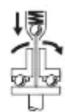
nauuuaananaananaananaananaanana (4) 2u
nuuuuuuuuuuuuuuuuuuuuuuuuuuuuuuuuuuuuuuuuuuuuuuuuuuuuuuuuuuuuuuuuuuuuuuuuuuuuuuuuuuuuuuuuuuuuuuuuuuuuuuuuuuuuuuuuuuuuuuuuuuuuuuuuuuuuuuuuuuuuuuuuuuuuuuuuuuuuuuuuuuuuuuuuuuuuuuuuuuuuuuuuuuuuuuuuuuuuuuuuuuUUUUUUUUUUUUUUUUUUUUUUUUUUUUUUUUUUUUUUUUUUUUUUUUUUUUUUUUUUUUUUUUUUUUUUUUUUUUUUUUUUUUUUUUUUUUUUUUUUUUUUUUUUUUUUUUUUUUUUUUUUUUUUUUUUUUUUUUUUUUUUUUUUUUUUUUUUUUUUUUUUUUUUUUUUUUUUUUUUUUUUUUUUUUUUUUUUUUUUUU
wnnnnnaaannnnnnnnnnn (6) nannn nn
ANGLE EXACT 14CF | 22CF | 29CF
nunnnnnnnnnnnnnnnnnnnnnnnnnnnnnnnnnnnnnnnnnnnnnnnnnnnnnnnnnnnnnnnnnnnnnnnnnnnnnnnnnnnnnnnnnnnnnnnnnnnnnnnnnnnnnnnnnnnnnnnnnnnnnnnnnnnnnnn
mnuuLED aauunnu (aunnuau J)
ANGLE EXACT 2 | 3 | 6 | 7 | 8 | 14CF | 15 |
17|22CF|23|29CF|30
lulunnuuugn nnaaannnnn nn annnnn (17) 0nnnnnnnnnnnnnnnnnnnnnnnnnnnnnnnnnnnnnnnnnnnnnnnnnnnnnnnnnnnnnnnnnnnnnnnnnnnnnnnnnnnnnnnnnnnnnnnnnnnnnnnnnnnnnnnnnnnnnnnnnnnnnnnnnnnnnnnnnnnnnnnnnnnnnnnn
LLED (16) n w LED 18) w w
Keselamatan personnel
Palma Tower 10th Floor
Jalan RA Kartini II-S Kaveling 6
Pondok Pinang, Kebayoran Lama
Thóng tin vê Tiéng on/Dó rung
Gia tri phat thai tieng on duoc xac minh phu hop voi EN 62841-2-2.
Múc áp suát am thanh theo dac tính A că dung cu dien thuong la 70 dB(A). Hé so bát dinh K = 3 dB.
Don nguyen 8BC, GT Tower, Tâng 08,
Duong 169, Tiep Khac Blvd, Sangkat Veal Vong, Khan 7 Makara, Phnom Penh
VAT TIN: 100 169 511
Tel.: +855 23 900 685
Tel.: +855 23 900 660
www.bosch.com.kh
Su thai bo

Dung cu dién, pin, phu kien và bao bi can duoc tí su dung theo quy dinh vê mi o truong.
Ban khong duoc ném dung cu dien vapin vao thung rac gia dinh!

Chi dānh choc cóc quoc gia thuoc khói Lien minh Chau Au (EU):
Các dung cu dien cám tay khong con giá tri su dung theo chi thi chau Au 2012/19/EU va ac quy/ pin bi hóng hoac dā qua su dung theo chi thi só
Ni-MH: Niken-kim loai hydraul
Jjlll llaa ylll oal sic aallll llll lal lal lal lal lal lal lal lal lal lal lal lal lal lal lal lal lal lal lal lal lal lal lal lal lal lal lal lal lal lal lal lal lal lal lal lal lal lal lal lal lal
J 1 a
auiu
Jol
oJg oJg aJg lo Jg Jg Jg Jg Jg Jg Jg Jg Jg Jg Jg Jg Jg Jg Jg Jg Jg Jg Jg Jg Jg Jg Jg Jg Jg Jg Jg Jg Jg Jg Jg Jg Jg Jg Jg Jg Jg Jg Jg Jg Jg Jg Jg Jg Jg Jg Jg Jg Jg Jg J g
Jg .aa aalll Jj 1 j 1 1 1 1 1 1 1 1 1 1 1 1 1 1 1 1 1 1 1 1 1 1 1 1 1 1 1 1 1 1 1 1 1 1 1 1 1 1 1 1 1 1 1 1 1
J 155u .g 2000 g J 155u 155u 155u 155u 155u 155u 155u 155u 155u 155u 155u 155u 155u 155u 155u 155u 155u 155u 155u 155u 155U
J 1 J 1 1 1 1 1 1 1 1 1 1 1 1 1 1 1 1 1 1 1 1 1 1 1 1 1 1 1 1 1 1 1 1 1 1
J L a 1000000000000000000000000000000000000000000000000000000000000000000000
JU JJJJU JJJJU JJJJU JJJJU JJJJU JJJJU JJJJU JJJJU JJJJU JJJJU JJJJU JJJJU JJJJU JJJJU JJJJU JJJJU JJJJU JJJJU JJJJU JJJJU JJJJU JJJJU JJJJU JJJJU JJJJU JUU
Jg jj J 1
Lgolal
Bolaj
Lgolal
Bolaj
Lgolal
Lgolal
Lgolal
Lgolal
Lgolal
Lgolal
Lgolal
Lgolal
Lgolal
Lgolal
Lgolal
Lgolal
Lgolal
Lgolal
Lgolal
Lgolal
Lgolal
Lgolal
Lgolal
Lgolal
Lgolall
aui jsslll pldwlg aolao nssu .i i 1jglll lpsb jai 出 .ii Jia aiaaiaaiaaiaiaiaiaiaiaiaiaiaiaiaiaiaiaiaiaiaiaiaiaiaiaiaiaiaiaiaiaiaiaiaiaiaiaiaiaiaiaiaiaiaiaiaiaiaiaiaiaiaiaiaiaiaiaiaiaiaiaiaiaiaiaiaiaiaiaiaiaiaia
#
JlKl I JdJ
J 1 J
UJd aEg Lg Ebl
jgllg lalolgl 1
. 11 11 11 11 11 11 11 11 11 11 11 11 11 11
aalaaalg aayrddl lalalalalalalal
(aJgSJI 1000 (aJgSJI aJgSJI aJgSJI aJgSJI aJgSJI aJgSJI aJgSJI aJgSJI aJgSJI aJgSJI aJgSJI aJgSJI aJgSJI aJgSJI aJgSJI
JooU UoUoUo
Uu uug U
a a a a a a a a a a a a a a
.
p5joo gjoll jol lawg doloo jwa
aui jwai ojai
aaii j 1000
gol jol j o 20 gil aal jll
jol gjo doolssw j 1
pS|Jol
aI Jolgl go bdd a
.1Jl 10
gwhjgUgUulU
.
auiuJ 11
aai jssal gaii gbi ggi liu uic
jlo jgUlgJolwajg JlaJg
gdd lll dduall jolck
. JJll logasuyu wolalj Uogji
a 1
.1JU 1J1g JIJI
387
g bgsaal jlglloljle
1 13. aui jSUI oJU
jIgJlOJI jLg JUJIJUW UJ
LgUJUuuiuue gUgU UjUc Uguao
a aia 1suiy
.0JbWJ
U. UaLaaS auiuJgSJI oaiI paae
aJUcIab] aJLa o gJaI ayuSJI sJJI
Ug y Su logigj yalll oogu saaill
jIJlUw
Ig aaiJ 109
Jlal 1sJg J
gubj sic ubjI yJl. alusllg
g 1aJUg JlaJl
ggluljglloosg
gjyai gglg jllg

.
JgJgJgJgJgJgJgJg
J
Jusss
2|3|6|7|8|15|17|23| ANGLE EXACT
30
UgU UgBbJdUgSULo
jIiWi oJgajl aLcK joLoRg golgallg
JgSdJlIg wlaJIg Iblj aIg
J. 15 JdSdWdUeSdUe
J 1
.1JUaLbI aJy oJgjo dJyS oJc
14CF | 22CF | 29CF ANGLE EXACT
Lw wIwI yIc aJyIyJyIyIyIyIy
aabdo a jj o jw wll jwll oljy
JgoljI JJI Jlaig. aagdo
:do aag o salg qo lo g! UgogU 50
Lbgs
.ajglaljUogJlJdJLJg
iJ. 1s sssss sssss
ooJgogj JooJooJooJoo
aababaiIgawJl aao 9 oogagall ajuqSJI
ooJol (2)
gJUgUUJU
027 wlao ylaolai (4)
(5)
22 22 aai (6)
w g jslw (8)
LJI UUc -gUJU Jwgo (9)
pJdJw dJgJwgo (10)
oJ 0000g 15gSsw J
.aaaiJ 1
.0sJoljooJl.
.
A
gI UkfoJg mool Joo
.aaJIJIgJJI JIJI 10J 5Jg
glalg aalalJdAuljSll oJl Jaa
doojg oJalgl dio aisIg JgJgJgJol
. b0 dgiwJ
AaJU Luaio Lp
ailllll b
LgjBaoJbI0
ooos
Jaaa aaaa aaa aaa aaa aaa
LJg glwIg JJJ jogjljawu

j1i jia liu
jg
aJLg jgJLgC
.1JauuJU JusuI oXc JooaiSuaa
Ug jIgjI gJgjI gol
.aaJssjI aosoo yic Jswl osc j
1g gJyJyJooJooJooJoo
Lulc Jusj jill Jswll abab cuaai
aaiu| uai jui
gJg jIg
ogg|jUbJWlUwSd aJLWJUJLcA1g

auiuuljglai
:JgJgj
Jcagglll lllllg jgljI yolll
iawgugbllgsswlll jglj
wJg logjIg jjjll
a a lo 0jgb s 0g g y.
oJslol Josll jgbll lalj
(Lc)aawlaiylaaljulgolwglag
1jgl aaaa aaaaa aaii ayao jajl lll
.(Lai aaoa oJl jol JI LJIyj oJilgabuiw,
- gaaJUe Jua
labyI gog Ic labyIg Iaia
pJJI UJU JUJU JUJU
Lg
gJyWll sag auiuJgSJI oaiI gos
.
aag aouuJ
a aaii jw w sdd.
J. a>gall g|gill |gall |gill |g|a|
23(jalwlu jg.
auiJUuJI
| 6 | 3 | 2 | ANGLE EXACT Āgɪljjɪ Ṭɪsɪaɪcɪbɪlɪsɪŋʌŋʌŋʌŋʌŋʌŋʌŋʌŋʌŋʌŋʌŋʌŋʌŋʌŋʌŋʌŋʌŋʌŋʌŋʌŋʌŋʌŋʌŋʌŋʌŋʌŋʌŋʌŋʌŋʌŋʌŋʌŋʌŋʌŋʌŋʌŋʌŋʌŋʌŋʌŋʌŋʌŋʌŋʌŋʌŋʌŋʌŋʌŋʌŋʌŋʌŋ | |
| 0 602 490 652 | 0 602 490 656 | 0 602 490 647 | Jæm Jæn Jæn Jæn Jæn Jæn Jæn Jæn Jæn Jæn Jæn Jæn Jæn Jæn Jæn Jæn Jæn Jæn Jæn Jæn Jæn Jæn Jæn Jæn Jæn Jæn Jæn Jæn Jæn Jæn Jæn Jæn Jæn Jæn Jæn | |
| 6/6 | 3/3 | 2/2 | \( \frac{1}{\text{ bi-j }} \) \( \frac{1}{\text{ bi-j }} \) | \( \frac{1}{\text{ bi-j }} \)/\( \frac{1}{\text{ bi-j }} \) \( \frac{1}{\text{ bi-j }} \) \( \frac{1}{\text{ bi-j }} \) \( \frac{1}{\text{ bi-j }} \) \( \frac{1}{\text{ bi-j }} \) \( \frac{1}{\text{ bi-j }} \) \( \frac{1}{\text{ bi-j }} \) \( \frac{1}{\text{ bi-j }} \) \( \left. \begin{array}{l} \text{ Jæn } \\ \text{ Jæn } \\ \text{ Jæn } \\ \text{ Jæn } \\ \text{ Jæn } \\ \text{ Jæn } \\ \text{ Jæn } \\ \text{ Jæn } \\ \text{ Jæn } \\ \text{ Jæn } \\ \text{ Jæn } \\ \text{ Jæn } \\ \text{ Jæn } \\ \text{ I } \\ \text{ Jæn } \\ \text{ Jæn } \\ \text{ Jæn } \\ \text{ Jæn } \\ \text{ Jæn } \\ \text{ Jæn } \\ \text{ Jæn } \\ \text{ Jæn } \\ \text{ Jæn } \\ \text{ Jæn } \\ \text{ Jæn } \\ \text{ Jæn } \\ \mathrm{{ISO}}{5393}\text{ Å}\text{ a}\text{ s}\text{ a}\text{ s }\text{ a }\text{ s }\text{ a }\text{ s }\text{ a }\text{ s }\text{ a }\text{ s }\text{ a }\text{ s }\text{ a }\text{ s }\text{ a }\text{ s }\text{ a }\text{ s }\text{ a }\text{ s }\text{ a }\text{ s }\text{ a }\text{ s }\text{ a }\text{ s }\text{ a }\text{ s } \) |
| 650 | 420 | 110 | \( \frac{1}{\text{ bi-j }} \) \( \frac{1}{\text{ bi-j }} \) | \( \frac{1}{\text{ bi-j }} \)/\( \frac{1}{\text{ bi-j }} \) \( \frac{1}{\text{ bi-j }} \) \( \frac{1}{\text{ bi-j }} \) \( \frac{1}{\text{ bi-j }} \)\( \frac{1}{\text{ bi-j }} \) \( \frac{1}{\text{ bi-j }} \) \( \frac{1}{\text{ bi-j }} \) \( \frac{1}{\text{ bi-j }} \) \( \frac{1}{\text{ bi-j }} \) \( \frac{1}{\text{ bi-j }} \) \( \frac{1}{\text{ bi-j }} \) \( \text{ Jæn } \) \( \text{ Jæn } \) \( \text{ Jæn } \) \( \text{ Jæn } \) \( \text{ Jæn } \) \( \text{ Jæn } \) \( \text{ Jæn } \) \( \text{ Jæn } \) \( \text{ Jæn } \) \( \text{ Jæn } \) \( \text{ Jæn} \) \( \text{ Jæn } \) \( \text{ Jæn } \) \( \text{ Jæn } \) \( \text{ Jæn } \) \( \text{ Jæn } \) \( \text{ Jæn } \) \( \text{ Jæn } \) \( \text{ Jæn } \) \( \text{ Jæn } \) \( \text{ Jæn }\left. \begin{array}{l} \text{ Jæn } \\ \text{ Jæn } \\ \text{ Jæn } \\ \text{ Jæn } \\ \text{ Jæn } \\ \text{ Jæn } \\ \text{ Jæn } \\ \text{ Jæn } \\ \text{ Jæn } \\ \text{ Jæn } \\ \text{ Jæn } \\ \text{} \\ \text{} \\ \text{} \\ \text{} \\ \text{} \\ \text{} \\ \text{} \\ \text{} \\ \text{} \\ \text{} \\ \text{} \\ \text{} \\ \text{} \\ \text{} \\ \text{} \\ \text{} \\ \text{} \\ \text{} \\ \text{} \\ \text{} \\ \text{} \\ \text{} \\ \text{} \\ \text{} \\ \text{} \\ \text {} \\ \text{} \\ \text{} \\ \text{} \\ \text{} \\ \text{} \\ \text{} \\ \text{} \\ \text{} \\ \text{} \\ \text{} \\ \text{} \\ \text{} \\ \text{} \\ \text{} \\ \text{} \\ \text{} \\ \text{} \\ \text{} \\ \text{} \\ \text{} \\ \text{} \\ \text{} \\ \text{} \\ \text{} \\ \text{ Jæn } \\ \text{ Jæn } \\ \text{ Jæn } \\ \text{ Jæn } \\ \text{ Jæn } \\ \text{ Jæn } \\ \text{ Jæn } \\ \text{ Jæn } \\ \text{ Jæn } \\ \text{ Jæn } \\ \text{ Jæn } \\ \text{ Jæn } \\ \text{} \\ \text{} \\ \text{}\\ \text{} \\ \text{} \\ \text{} \\ \text{} \\ \text{} \\ \text{} \\ \text{} \\ \text{} \\ \text{} \\ \text{} \\ \text{} \\ \text{} \\ \text{} \\ \text{} \\ \text{} \\ \text{} \\ \text{} \\ \text{} \\ \text{} \\ \text{} \\ \text{} \\ \text{} \\ \text{} \\ \text{} \\ \text{}\\ \text{} \\ \text{} \\ \text{} \\ \text{} \\ \text{} \\ \text{} \\ \text{} \\ \text{} \\ \text{} \\ \text{} \\ \text{} \\ \text{} \\ \text{} \\ \text{} \\ \text{} \\ \text{} \\ \text{} \\ \text{} \\ \text{} \\ \text{} \\ \text{} \\ \text{ Jæn } \\ \text{ Jæn }\\ \text{ Jæn }\\ \text{ Jæn }\\ \text{ Jæn }\\ \text{ Jæn }\\ \text{ Jæn }\\ \text{ Jæn }\\ \text{ Jæn }\\ \text{ Jæn }\\ \text{ Jæn }\\ \text{ Jæn }\\ \text{ Jæn }\\ \text{ Jæn }\\ \text{Jæn }\\ \text{ Jæn }\\ \text{ Jæn }\\ \text{ Jæn }\\ \text{ Jæn }\\ \text{ Jæn }\\ \text{ Jæn }\\ \text{ Jæn }\\ \text{ Jæn }\\ \text{ Jæn }\\ \text{ Jæn }\\ \text{ Jæn }\\ \text{ Jæn } \\ \text{ Jæn }\\ \text{ Jæn }\\ \text{ Jæn }\\ \text{ Jæn }\\ \text{ Jæn }\\ \text{ Jæn }\\ \text{ Jæn }\\ \text{ Jæn }\\ \text{ Jæn }\\ \text{ Jæn }\\ \text{ Jæn }\\ \text{Jæn }\\ \text{Jæn }\\ \text{Jæn }\\ \text{Jæn }\\ \text{Jæn }\\ \text{Jæn }\\ \text{Jæn }\\ \text{Jæn }\\ \text{Jæn }\\ \text{Jæn }\\ \text{Jæn }\\ \text{Jæn }\\ \text{Jæn } \\ \text{Jæn }\\ \text{Jæn }\\ \text{Jæn }\\ \text{Jæn }\\ \text{Jæn }\\ \text{Jæn }\\ \text{Jæn }\\ \text{Jæn }\\ \text{Jæn }\\ \text{Jæn }\\ \text{Jæn }\\ \text{Jæn }\\ \text{ Jæn }\\ \text{Jæn }\\ \text{Jæn }\\ \text{Jæn }\\ \text{Jæn }\\ \text{Jæn }\\ \text{Jæn }\\ \text{Jæn }\\ \text{Jæn }\\ \text{Jæn }\\ \text{Jæn }\\ \text{Jæn } \\ \text{Jæn } \\ \text{Jæn }\\ \text{Jæn }\\ \text{Jæn }\\ \text{Jæn }\\ \text{Jæn }\\ \text{Jæn }\\ \text{Jæn }\\ \text{Jæn }\\ \text{Jæn }\\ \text{Jæn }\\ \text{Jæn }\\ \text{ Jæn }\\ \text{ Jæn }\\ \text{ Jæn }\\ \text{ Jæn }\\ \text{ Jæn }\\ \text{ Jæn }\\ \text{ Jæn }\\ \text{ Jæn }\\ \text{ Jæn }\\ \text{ Jæn }\\ \text{ Jæn } \\ \text{ Jæn } \\ \text{ Jæn }\\ \text{ Jæn }\\ \text{ Jæn }\\ \text{ Jæn }\\ \text{ Jæn }\\ \text{ Jæn }\\ \text{ Jæn }\\ \text{ Jæn }\\ \text{ Jæn }\\ \text{ Jæn }\\ \text{ Jæn }\\ \text{} \\ \text{} \\ \text{} \\ \text{} \\ \text{} \\ \text{} \\ \text{} \\ \text{} \\ \text{} \\ \text{} \\ \text{} \\ \text{} \\ \text{} \\ \text{} \\ \text{} \\ \text{} \\ \text{} \\ \text{} \\ \text{} \\ \text{} \\ \text{} \\ \text{} \\ \text{} \\ \text{} \\ \text{Jæn } \\ \text{Jæn } \\ \text{Jæn } \\ \text{Jæn } \\ \text{Jæn } \\ \text{Jæn } \\ \text{Jæn } \\ \text{Jæn } \\ \text{Jæn } \\ \text{Jæn } \\ \text{Jæn } \\ \text{Jæn } \\ \text{Jæn } \\ \text{} \\ \text{} \\ \text{} \\ \text{} \\ \text{} \\ \text{} \\ \text{} \\ \text{} \\ \text{} \\ \text{} \\ \text{} \\ \text{} \\ \text{} \\ \text{} \\ \text{} \\ \text{} \\ \text{} \\ \text{} \\ \text{} \\ \text{} \\ \text{} \\ \text{} \\ \text{} \\ \text{} |
| 9,6 | 9,6 | 9,6 | \( \frac{1}{\text{ bi-j }} \) | \( \frac{1}{\text{ bi-j }} \) |
| 9,6 | 9,6 | 9,6 | \( \frac{1}{\text{ bi-j }} \) | \( \frac{1}{\text{ bi-j }} \) |
| 9,6 | 9,6 | 9,6 | \( \frac{1}{\text{ bi-j }} \) | \( \frac{1}{\text{ bi-j }} \) |
| 9,6 | 9,6 | 1,0 | \( \frac{1}{\text{ bi-j }} \) | \( EPTA-Procedure 01:2014 \) |
| IP 20 | IP 20 | IP 20 | \( \frac{1}{\text{ Jæn } } \) |
| 15 | 8 | 7 | ANGLE EXACT Äggljlll lalssiaeaàalgllll lalssiaeaàalgllll lalssiaeaàalgllll lalssiaeaàalgllll lalssiaeaàalgllll lalssiaeaàalgllll lalssiaeaàalgllll lalssiaeaàalgllll lalssiaeaàalgllll lalssiaeaàalgllll lalssiaeaàalgrlll lalssiaeaàalgllll lalssiaeaàalgllll lalssiaeaàalgllll lalssiaeaàalgllll lalssiaeaàalgllll lalssiaeaàalgllll lalssiaeaàalgllll lalssiaeaàalgllll lalssiaeaàalgllll lalssiaeaàal gllll lalssiaeaàalgllll lalssiaeaàalgllll lalssiaeaàalgllll lalssiaeaàalgllll lalssiaeaàalgllll lalssiaeaàalgllll lalssiaeaàalgllll lalssiaeaàalgllll lalssiaeaàalgllll lalssiaeaàalglll lalssiaeaàalgllll lalssiaeaàalgllll lalssiaeaàalgllll lalssiaeaàalgllll lalssiaeaàalgllll lalssiaeaàalgllll lalssiaeaàalgllll lalssiaeaàalgllll lalssiaeaàalgllll lalssiaeaàal glll lalssiaeaàalgllll lalssiaeaàalgllll lalssiaeaàalgllll lalssiaeaàalgllll lalssiaeaàalgllll lalssiaeaàalgllll lalssiaeaàalgllll lalssiaeaàalgllll lalssiaeaàalgllll lalssiaeaàal | ||
| 0 602 490 650 | 0 602 490 651 | 0 602 490 669 | Jρρρρρρρρρρρρρρρρρρρρρρρρρρρρρρρρρρρρρρρρρρρρρρρρρρρρρρρρρρρρρρρρρρρρρρρρρρρρρρρρρρρρρρρρρρρρρρρρρρρρ | ||
| 15/15 | 9/9 | 7/7 | ηηηηηηηηηηηηηηηηηηηηηηηηηηηηηηηηηηηηηηηηηηηηηηηηηηηηηηηηηηηηηηηηηηηηηηηηηηηηηηηηηηηηηηηηηηηηηηηηηηηη | ||
| 250 | 420 | 110 | ηηηηηηηηηηηηηηηηηηηηηηηηηηηηηηηηηηηηηηηηηηηηηηηηηηηηηηηηηηηηηηηηηηηηηηηηηηηηηηηηηηηηηηηηηηηηηηηηηη | ISO 5393 chpbs lalssiaeaàalgllll lalssiaeaàalgllll lalssiaeaàalgllll lalssiaeaàalgllll lalssiaeaàalgllll lalssiaeaàalgllll lalssiaeaàalgllll lalssiaeaàalgllll lalssiaeaàalgllll lalssiaeaàalglll lalssiaeaàalgllll lalssiaeaàalgllll lalssiaeaàalgllll lalssiaeaàalgllll lalssiaeaàalgllll lalssiaeaàalgllll lalssiaeaàalgllll lalssiaeaàalgllll lalssiaeaàalgllll lalssiaeaàalglllt lalssiaeaàalglllt lalssiaeaàalglllt lalssiaeaàalglllt lalssiaeaàalglllt lalssiaeaàalglllt lalssiaeaàalglllt lalssiaeaàalglllt lalssiaeaàalglllt lalssiaeaàalglllt lalssiaeaàalglll t | |
| 9,6 | 9,6 | 9,6 | ηηηηηηηηηηηηηηηηηηηηηηηηηηηηηηηηηηηηηηηηηηηηηηηηηηηηηηηηηηηηηηηηηηηηηηηηηηηηηηηηηηηηηηηηηηηηηηηηηηΩ | Jn n Jn n Jn n Jn n Jn n Jn n Jn n Jn n Jn n Jn n Jn n Jn n Jn n Jn n Jn n Jn n Jn n Jn n Jn n Jn n Jn n Jn n Jn n Jn n Jn n Jn n Jn n Jn n Jn n Jn n Jn n Jn n Jn n Jn n J. | |
| ΩΩ | ΩΩ | ΩΩ | Jn n Jn n Jn n Jn n Jn n Jn n Jn n Jn n Jn n Jn n Jn n Jn n Jn n Jn n Jn n Jn n Jn n Jn n Jn n Jn n Jn n Jn n Jn n Jn n Jn n Jn n Jn n Jn n Jn n Jn n Jn n Jn n Jn no | ||
| 1,0 | 1,0 | 1,0 | ηηηηηηηηηηηηηηηηηηηηηηηηηηηηηηηηηηηηηηηηηηηηηηηηηηηηηηηηηηηηηηηηηηηηηηηηηηηηηηηηηηηηηηηηηηηηηηηηη | EPTA-Procedure 01:2014 Jn n Jn n Jn n Jn n Jn n Jn n Jn n Jn n Jn n Jn no | |
| IP 20 | IP 20 | IP 20 | Jn n Jn n Jn n Jn no | ||
jg aagaaaagagab20 g
JU 1sW uu wll Jn Gd 1
JG 0
Ll (9°113) 45 g (9°32)
.
95 1% g|lj aclill wllgll cksao s jggj pui yllgll bjj j, j, j, j, j, j, j, j, j, j, j, j, j, j, j, j, j, j, j, j, j, j, j, j, j, j, j, j, j, j, j, j, j, j, j, j, j, j, j, j, j, j, j, j, j, j, j, j, j, j, j
glllglllbjiJj
ANGLE EXACT2 | 3 | 6 | 7 | 8 | 15|4|2|23|p p biaJlly jj j j j j4EXACT.
30
aJglll lI glll I bI y Jy j kJy Jy Jy Jy Jy Jy Jy Jy Jy Jy Jy Jy Jy Jy Jy Jy Jy Jy Jy Jy Jy Jy Jy Jy Jy Jy Jy Jy Jy Jy Jy Jy Jy Jy Jy Jy Jy Jy Jy Jy Jy Jy Jy Jy Jy Jy Jy Jy Jy Jy JyJ yJ yJ yJ yJ yJ yJ yJ yJ yJ yJ yJ yJ yJ yJ yJ yJ yJ yJ yJ yJ yJ yJ yJ yJ yJ yJ yJ yJ yJ yJ yJ yJ yJ yJ yJ yJ yJ yJ yJ yJ yJ yJ yJ yJ yJ yJ yJ yJ yJ yJ
ANGLE EXACT14CF | 22CF | 29CF
aolalagglj acllwlglllcdo ygai ablao jooj,jssw ssc g0oosy aolalal, jalw,pajpab,gawg aqlqall alog gl aablal
aIgll gll lglolg 10000000000000000000000000000000000000000000000000000000000
ANGLE EXACT14CF | 22CF | 29CF
Ld aalldaablaall ojg jy Lj g.0 s yogjall ayglll acliall lgl 1ggull aoliso daalao ju jagjjssay uasiall jullmuu wul elisao .aaalldaablaall Jd .aalall ojqui caileiy
gulll ojq
g jj j j j j j j j j j j j j j j j j j j j j j j j j j j j j j j j j j j j j j j j j j j j j j j j j j j j j j j j j j j j j j j j j j j j j j j j j j j j j j j j j j j j j j j j j j jjjjjjjjjjjjjjjjjjjjjjjjjjjjjjjjjjjjjjjjjjjjjjjjjjjjjjjjj
Jull
J 1000000000000000000000000000000000000000000000000000000000000000000000000000
aIJI I I I pbiJ I aJIO J dJ 1 .JU aJJI aJUgJ A
Jg4EXACT aIbIJI IJI pabIOJI JgA
JgJeOJIJI BJI gNJIJI AJIyRIJI
JIJIJIJI JJIJIJI JJIJIJI JJIJIJI
JU JU. juogj (23) juagj JU wgo J U JU WJUACg g u.JUWJU WJU JU WJU JU WJU JU WJU JU WJU JU WJU JU WJU JU WJU JU WJU JU WJU JU WJU JU WJU JU WJU JU WJU JU WJU JU WJU JU WJU JU WJU JU WJU JU WJU JU WJU
aJgUw-1
eJll
gJJI UJwgo 2
| akswlll lssl jdsj syybbl ydljyckslj (10ks) lskw | aikswlll lssl jdsj ydybbl yckslj (μksw) lskw |
| akswlll lssl jdsj jssj no jno lsblll aikswll sdc allsgn jno jdo cysd ydlj yckslj wg öjrgäll sic nlaalwll | lkblll lssl ydaalj cllj gll aikswlll akswlll jnaalwll |
JooJIaLoc JooSoy
J 1 J 1 J 1 J 1 J 1 J 1 J 1 J 1 J 1 J 1 J 1 J 1 J 1 J 1 J 1 J 1 J 1 J 1 J 1 J 1 J 1 J 1 J 1 J 1 J 1 J 1 J 1 J 1 J 1 J 1 J 1 J 1 J 1 J 1 J
2|3|6|7|8|15 ANGLE EXACT
auiuul uUgU U Kdo n o gill I gjg 10 go Ugl Ugl Uj Uj pJ aolall aygl J UaiuI J) aogj 1/4 Ucl jgbao
glj gJgJgJgJgJgJgJgJgJgJgJgJgJgJgJgJgJgJgJgJgJgJgJgJgJgJgJgJgJgJgJgJgJgJgJgJgJgJgJgJgJgJgJgJgJgJgJgJgJgJgJ
(0607453620)
17|23|30 ANGLE EXACT
acllll lglll kdo ngo glll lge ggo (sglj llgl b j w j pksj aolall agglj l sall) 3/8 c1j gba
(0607451618)
Jshll osc
(2) 11111111111111111111111111111111111111111111111
JsWl osc
(1) jj j j j j j j j j j j j j j j j j j j j j j j j j j j j j j j j j j j j j j j j j j j j j j j j j j j j j j j j j j j j j j j j j j j j j j j j j j j
jolc jlll osc jlsjll lgc joral 1000000000000000000000000000000000000000000000000000000000000000000000
2|3|6|7|8|15 ANGLE EXACT
aclll lgll kdo no ggl l jg ggo (glj glj b jw jp aolal aggljll) aog 1/4 wds
(0607453618)
dolag qJl gLo uSj
gJgJJI Jbl)C(
ANGLE EXACT2 | 3 | 6 | 7 | 8 | 14C
17 | 22CF | 23 | 29CF | 30
JgWJI JIJI JIJI JIJI JIJI JIJI JIJI
J 1
Uggl UwLgD-Sub 9,6,2l9
Jg14,4. gwi dglbLg
(28)
aio d<g g| pksjy jolal lgllll lgllll jg aublaI Iu IpaiaI Iglo kI aublaI CbI paiaI Jn Uusgill uLg (26)
jSJIJI (14) 1JgJlOaJI UJgJia liaiu
(13) 工 工 工 工 工 工 工 工 工 工 工 工 工 工 工 工 工 工 工 工 工 ^ 2
aJU 28) aJU JU
(12)UJlJI JJJJWJLgJGLJ 1. Wgssu UKwAaIyRSLJ OJdJ 0dsJUaJI (26)UJUgUllMwLaJdA 1. uoo aaiuuiu
(27) 2015-2016 (25) 100000000000000000000000000000000000000000000000000000000000000000000000
.25) 100gll lsso o 100gll sL g g g g g g g g g g g g g g g g g g g g g g g g g g g g g g g g g g g g g g g g g g g g g g g g g
GgUgJbJjwJ JLa Jd D (D gJgJJI bJl) Jsuill Jw
jolgl jolw lsc jkjlgl jol 1 ooc bpoj np jl .gul .uol y 1000 g 2000 1000 1000 1000 1000
2|3|6 ANGLE EXACT
acll llll l kdo n eo gill | jg jg 20 po aaiu u llgl b jw j wj y aalolll agll jll fJ) aog 1/4 mss s
2|3|6|7|8|15 ANGLE EXACT
acllll glll kdo jglll ljg jg jg 1000000000000000000000000000000000000000000000000000000000000000
JsWll osc uJ
JdA. pOJI (29) gJUWJU JI UJU 1 (1) JUWJU .JUWJU
1/4)(a)1gulldawlωw-ωg
lalg jzllj 1a
pjc U|UgogU pui UJ kU 13
.ubuagwUJbJI
JdJl dJ
JU 1uO uJgS JooJ Uc pS JI Ejj
1JU01Ksw labw o j (I)gogic psej (J)
a 17 aJ Jd j
.1JUdolio 1
jIbJoo aolaoauiuS sxcuoooswJ!
jli kai joo jg 4,5 g 1j gEXACT
.1jgJl pjc paolil jgUll Jaaa dla aSji
EXACT jIb JgJgS Ss
jElisai jui jgi 7,5Lc aD uo o jUg jos
(ajjJgW) aldo ngly jzda aala kji
Jshll 0s
Jwll ooc Jd)1(wwsdgabao
oJlJUJI)2.1uJaaWuJU
J
(2) 0dJ JnJn (1) JdJdJdJd
gjU lacawloS sawuIg
山
aJauI Jgj
.aaaii i jjgl
.
Jusj joo ayggl eliaS,aa
gjx1j 10aaggl jl0g a
JuswIgBzUwA,2j3JgIgIgJgJg
aJyLxI JbJ 0,duJgSJI oJJI
J
LgJ 1 JyJgJ Ld JyJ Lsic
JgJololjol jol gai jq qjg JgJol
)14(:
olj lglai o1l bog aui jSll Jos
jIgJl)14(jlo)Iwgo
U
F(jgJl jil) jlgjll
(14) jIgJl oJI lIgai liao Jcbea
aaggaaJgJgJgJg
glc bawl, gllj jg
.ajll jj Jwll 14) jgJol jgl
aiaa aai gglg jj
.1411111111111111111
Jusll
Uls l! Ugul uog oL (18) Ua
JgJgJgJgJgJgJgJgJgJgJgJgJgJgJgJgJgJgJgJgJgJgJgJgJgJgJgJgJgJgJgJgJgJgJgJgJgJgJgJgJgJgJgJgJgJgJgJgJgJgJ
jjj jccd dddd d 18
jj Lc J 13(
aui jgSll ooll jaiuai g
.0juiy jaoai jaoiug
a9 JooJIgJooJooJooJoo
.
labylg uuswll
lab! ajjgulgul jua
Lgbu bJgJp Jb
sic yuuiw g. jgdoJlaoj
gww 1JUJgJU pjc UgogJ
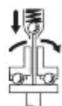
go UJxU yUgU elo oI sWUI sic: sWJ
aalgllll llll aaiill lssw jy y

x_9 = 12
aio bawl ayuysll oosll uusw wjol
lablg qikull13
Ldlu Lglogg ayyss
.ogaiJgJgJpjcUJUGgJLqua
4UJJIJIJIJIJIJIJIJIJIJIJIJIJIJIJIJIJIJIJIJIJIJIJIJIJIJIJIJIJIJIJIJIJIJIJIJIJIJIJIJIJIJIJIJIJIJIJIJIJIJIJIJIJIJIJIJIJIJIJIJIJIJIJIJIJIJIJIJIJIJIJIJIJIJIJIJIJIJIJIJIJIJIJIJIJIJIJIJIJIJIJIJIJIJIJIJIJIJIJIJIJ
(6) aLg jJJJ J 15gjj JaaJcJ
14CF | 22CF | 29CF ANGLE EXACT
aablaall jjll ojjy aagjll logalll cji jll jwuw g l w! Jsw Lw
Robert Bosch Morocco SARL
gjoo oo o jlll 53
JU 20300
+212529314327:JJI
sav.outillage@ma.bosch.com: g_j
jla
p.p. 2gLaJg oJlaU jilo
131gdsuJgds
Jlae ablw 112 (5g)
+968 99886794:
malatanpowertools@malatan.net:JgjS!
j
p.o. uJuU UgUaUgU
.51 ggsu 8gss
+974 40065458:aaJU
+974 4453 8585 :μsLg
csd@icsdoha.com:JgjzJ!
aJgewll aJyJI JdlaJI
(gSuaiaIulssaullalgag
[1] 14.
21431
1528 +966 2 6672222 :
+966 2 6676308:μsLg
roland@eajb.com.sa:JgJlJy
UJgW
aUgSJI UgSJUdawgo
1030 gg s u y ggs
U
+963212116083:
rita.dallal@ hotmail.com:gjgrs!
uig
p.o.3. uuug uogg Ug
SsU UJg gag a jlaI J
LdJlSJJ dUg aJI JU psc J0
.1sao ajjal jIgpojc buo
g aJU
.ugao uuaaaio uig jno baofo
aJyssjooJ Uol Jc aboall
Ulac 0ooggulg jujdojjo
goggJW
aaijbuiiJg
UaIull Uj. aIuI Uc abJoo
.dgjIJI
pIddwJlJluwUg Jdo
aalol aalol alil 1e lallldo jso
ogwJl jIgJI gbl aIyL aIuog
JgIJI gboa aIJI Uloglaolg auuaeill
:gww.bosch-pt.con
Bosch
Llaia oogaa bJwaiwi 1 JnS13
.qljloog
gag gogaa bgl gljIJwaiwi jI JwJ sic
Lg g jolll llll g j oall p j s j jj
aaii gia aagl
jJlJI
Jiww
auiolj uJdai aobio
06000
:cl+213(0)9824009
:LμS Lg+213 (0) $ 420 156
:gJgJ! sav@siestal-dz.com
J
aioiullooloojolpoiaawgo
Jaiiaobio, jyjw ojiw gjjb jyjla aSoo
+97317704257:μs<
h.berjas@eajb.com.sa:gj
jao
RBEG-LLC
Jnnn nn Jll 22
Jggl JgJg
00111799
:gjSJ|JU
boschegypt.powertools@eg.bosch.com
J
LgglgisUuagallacgao
JiaJJJb0EJw
1
+9647901906953:
+97143973851:J
2014w9jc hpsch@sahbatechnology.com:gjgjLJy
J
J-Roots Arabia J
aJ37uolU,uuu uul
Ulac 11194
+962 65545778:
bosch@rootsjordan.com:gjgjkl
aai jollieioo -oaglljluw
aJlU
:J+97165932777
山 山 山 + 9 7 1 6 5 3 3 2 2 6 9
:gjskj, npowertools@centra
J
aJlJI JJIg aWg
JdJlJolJUoJol. JjJgJgJoo
:J+967-1-202010
:1 μS Lg+967-1-279029
:gjU Jytech-tools@abualre
auiy
auiuiei joi joiai
aJb. aJssllg gIgllg sJolg
aI aI I yI aI I gJb Jc AaI I aI I aI
.

:JgJl JgJb
gjgJU gU 2012/19/EUu
wag, jusssu wJ aJl JI JI JI JI JI JI JI JI
gU d gU12006/66/ECgU
o d y e Ls aSlaaasllg aaaall lull/ps
g l g 10g 10g 10g 10g 10g 10g 10g 10g 10g 10g 10g 10g 10g 10g 10g 10g 10g 10g 10g 10g 10g 10g 10g 10g 10g 10
JgLwJlJ 1 Lw g JsSgS L
.1s d j gj oLswjl j 1jol
JiS CwI J Sgwh Jy Iow wlgdsjg
.ogwh laow cwsjl olsw
L
LwUgjyLs .duu dAulggs Jd .si slI Lolaw
. 1000000000000000000000000000000000000000000000000000000
aW aJoo
g g jgl g w,dlg l sioj uol .siS g a.
uusg g noj du uolil g 1sL UaBg 8baw
uJlqI G iRg qy Bn oj ly loa w la
. yU
<ugjuljUgawjzjJd
. 100000000000000000000000000000000000000000
4oJaiwI JyJyol
Jn Jn Jn Jn Jn Jn Jn Jn Jn Jn Jn Jn Jn Jn Jn Jn Jn Jn Jn Jn Jn Jn Jn Jn Jn Jn Jn Jn Jn Jn Jn Jn Jn Jn Jn Jn Jn Jn Jn Jn Jn Jn Jn Jn Jn Jn Jn Jn Jn Jn Jn
jI jI bI jI oI aI aI aI aI aI aI aI aI aI aI aI aI aI aI aI aI aI aI aI aI aI aI aI aI aI aI aI aI aI aI aI aI aI aI aI aI aI aI aI aI aI aI aI aI aI aI aI aI aI aI
gjcblydgljdlgjydoaowl
jlywlaogdjgswjljtaLal
wlaotgsw.
LJGdsgwsLal
LJWLaJgws.
LJGdsgwsLal
LJGdsgwsLal
LJGdsgwsLal
LJGdsgwsLal
LJGdsgwsLal
CwS L O Ss Wl JjI L sJy J jS Wl Sgbl .SiSi o laWl o w SjL dwi I Jpaiio Jc J S J S Wl J SsO O y Dcl Jy J J Gw Wj d jn g SiW L .djw
sLj slos L jil Jljl SjI 1slo 1u wJU JnJr. uJ 1J 1J 1J 1J 1J 1J 1J 1J 1J 1J 1J 1J 1J 1J 1J 1J 1J 1J 1J 1J 1J 1J 1J 1J 1J 1J 1J 1J 1J 1J 1J 1J 1J 1
slososgdojgljlljlggsjg Ssi jlwhljgwsdsw cjsjlw
oogdojgljla slosjldusjds
wi jdydow sjljdu wJksoo .sJuIjelI Jsgw
jwgjw
Jusssaaa a bao jg jjI g Jy Jg Jg Jg Jg Jg Jg Jg Jg Jg Jg Jg Jg Jg Jg Jg Jg Jg Jg Jg Jg Jg Jg Jg Jg Jg Jg Jg Jg Jg Jg Jg Jg Jg Jg Jg Jg Jg Jg Jg Jg Jg Jg Jg Jg Jg Jg Jg Jg Jg Jg J
LgawgSsJGiaI SlaiaI J
J 1 J 1 J 1 J 1 J 1 J 1 J 1 J 1 J 1 J 1 J 1 J 1 J 1 J 1 J 1 J 1 J 1 J 1 J 1 J 1 J 1 J 1 J 1 J 1 J 1 J 1 J 1 J 1 J 1 J 1 J 1 J 1 J 1 J 1 J
Jg i slw g I g Jg Jg Jg Jg Jg Jg Jg Jg Jg Jg Jg Jg Jg Jg Jg Jg Jg Jg Jg Jg Jg Jg Jg Jg Jg Jg Jg Jg Jg Jg Jg Jg Jg Jg Jg Jg Jg Jg Jg Jg Jg Jg Jg Jg Jg Jg Jg Jg Jg Jg J g J g J g J g J g J g J g J g J g J g J g J g J g J g J g J g J g J g J g J g J g J g J g
JJJJJJJJJJJJJJJJJJJJJJJJJJJJJJJJJJJJJJJJJJJJJJJJJJJJJJJJJJJJJJJJJJJJJJJJJJJJJJJJJJJJJJJJJJJJJJJJJJJJJJJJJJJJJJJJJJJJJJJJJJJJJJJJJJJJJJJJJJJJJJJJJJJJJJJJJJJJJJJJJJJJJJJJJJJJJJJJJJJJJJJJJJJJJJJJJJJJJJJJJjj
o slawl l qjul j bao g y sljI J
a d j bi j g u j 1 ggi U sU d s
s jlguo d jia o lqjul j o slaw .slw
. g g jg jgdu
Jl jI JI JI JI JI JI JI JI JI JI JI JI JI JI JI JI JI JI JI JI JI JI JI JI JI JI JI JI JI JI JI JI JI JI JI JI JI JI JI JI JI JI JI JI JI JI JI JI
J JlJua g Jaljgdo d Js Jgag w Jg jio
jui jglguiu lSao L
4o laow uai g yu
.0s0u w1 d s 1j jwsw JSo
duwgu g osi jgjduwgu dduwglj juabo Jds2b,g,swoos
a a 1
.1j j j j j j j j j j j
Jg g w g 10000000000000000000000000000000000000000000000000000000000000000000000000000000
| 172330 | |||
| Nm17/1323/2020/22/22/22/22/22/22/22/22/22/22/22/22/22/22/22/22/22/22/22/22/22/22/22/22/22/22/22/22/22/22/22/22/22/22 | ### | ||
| 560320220 | -1min | ### | |
| V14,414,414,4 | ### | ||
| ### | ### | ### | ### |
| kg1,51,51,5 | ### | ||
| IP 20IP 20IP 20 | ### | ||
| 14CF22CF29CF | ### | |||
| 0 602 490 691 | 0 602 490 693 | 0 602 490 690 | ### | |
| Nm1016200 | ### | |||
| 340440300 | -1min | (A) ### | ||
| V9,614,414,4 | ### | |||
| ### | ### | ### | ### | |
| kg1,01,51,5 | ### | |||
| IP 20IP 20IP 20 | ### | |||
g jj ciu i g uo .dj l jg a j s j j u y j g liu j g d u w u j u u u u u u u u u u u u u u u u u u u u u u u u u u u u u u u u u u u u u u u u u u u u u u u uu uu uu uu uu uu uu
| 14,4 | 14,4 | 12,0 | 12,0 | 9,6 | 9,6 | Ni-Cd bārsi dāsīn |
| 2 607 335 | 2 607 335 | 2 607 335 | 2 607 335 | 2 607 335 | 2 607 335 | shārzō gīn |
| 655 | 881 | 375 | 879 | 659 | 877 | |
| 12 | 12 | 10 | 10 | 8 | 8 | laḥdādāgādābārsi lq |
| 14,4 | 14,4 | 12,0 | 12,0 | 9,6 | 9,6 | V |
| 2,4 | 1,8 | 2,4 | 1,8 | 2,4 | 1,8 | Ah |
| 0,80 | 0,70 | 0,70 | 0,65 | 0,50 | 0,45 | kg |
| AL 2450 DV | AL 2450 DV | AL 2450 DV | AL 2450 DV | AL 2450 DV | AL 2450 DV | dāsīn |
GNTC UJd sOiiS UjjS uD jgoo (s)U JILO 150s Jbq J SjUJJW JJW
jg1 oJ5L
jg10gL)8(uljqdu
.50000000
jg0j8)8(j1jg
JwJdS)15.(xjLy L
<uljqoJg jg
.1JiisIolkissjgI
jjw
:ddSi Ulgoo J Lgul
.iiuui ggaoglwwj
aLwgs L CwI J SsOgJgJgAaLwgs
.duo glao loaw jj|j|a bgo
<siIg jjg jJw
.wwl wluo gjg jgswd julg
jLw oLsw sAL 2450 DVgaa (A
jduu (22) dawgJ L J (21)w oKiw
JU WJU LJI (11) g JU S JU g jjJ U.
.1s olaowl jwj 1 sj y jg
APT(Akku Pack Top) jjwJl l y jyI LgI JgI jgB d s o w dIw gB jjwO kssu Iy
.
Henk Becker Helmut Heinzelmann
Chairman of Executive Head of Product Certification
Management

V.H. M = 90^
Robert Bosch Power Tools GmbH, 70538 Stuttgart, GERMANY
Stuttgart, 05.03.2019