
Professional 180-LI 06019G5123 - Screwdriver BOSCH - Free user manual and instructions
Find the device manual for free Professional 180-LI 06019G5123 BOSCH in PDF.
| Brand | Bosch |
| Model | Professional 180-LI (ref. 06019G5123) |
| Product type | Cordless impact screwdriver |
| Nominal voltage | 18 V |
| No-load speed | 0 - 2,800 rpm |
| Impact rate | 0 - 3,600 min⁻¹ |
| Max torque (hard screwdriving) | 160 Nm (1/4" hex) / 180 Nm (1/2" square) depending on model |
| Tool holder | 1/4" hex socket or 1/2" square drive |
| Weight (according to EPTA) | 1.7 kg (GDR) / 1.8 kg (GDX) |
| Power supply | 18 V Lithium-Ion battery (recommended GBA 18V... or ProCORE18V...) |
| Battery charge indicator | Green LEDs (3 or 5 depending on battery) |
| Technologies | Electronic Cell Protection (ECP), PowerLight |
| Safety | Protection against deep discharge, battery lock |
| Noise level (sound pressure) | 96 dB(A); power 107 dB(A) |
| Vibration level | 9.5 m/s² (screw/nut tightening) |
| Maintenance | Replaceable carbon brushes (check every 2-3 months) |
| Operating temperature | -20 °C to +50 °C |
| Recommended charger | GAL 18..., GAX 18..., GAL 36... |
| Included accessories | Screwdriver bit, universal bit holder, belt clip |
| Rotation direction | Switchable (right/left) via selector |
| Variable speed | Yes, by trigger pressure |
| Intended use | Screwing and unscrewing screws, tightening/loosening nuts |
| After-sales service | Direct online customer service, spare parts on bosch-pt.com |
Frequently Asked Questions - Professional 180-LI 06019G5123 BOSCH
User questions about Professional 180-LI 06019G5123 BOSCH
0 question about this device. Answer the ones you know or ask your own.
Ask a new question about this device
Download the instructions for your Screwdriver in PDF format for free! Find your manual Professional 180-LI 06019G5123 - BOSCH and take your electronic device back in hand. On this page are published all the documents necessary for the use of your device. Professional 180-LI 06019G5123 by BOSCH.
USER MANUAL Professional 180-LI 06019G5123 BOSCH
GDR | GDX Professional
180-LI
Robert Bosch Power Tools GmbH
70538 Stuttgart
GERMANY
www.bosch-pt.com
1609 92A 5XY (2020.07) DOC/229

natural_image
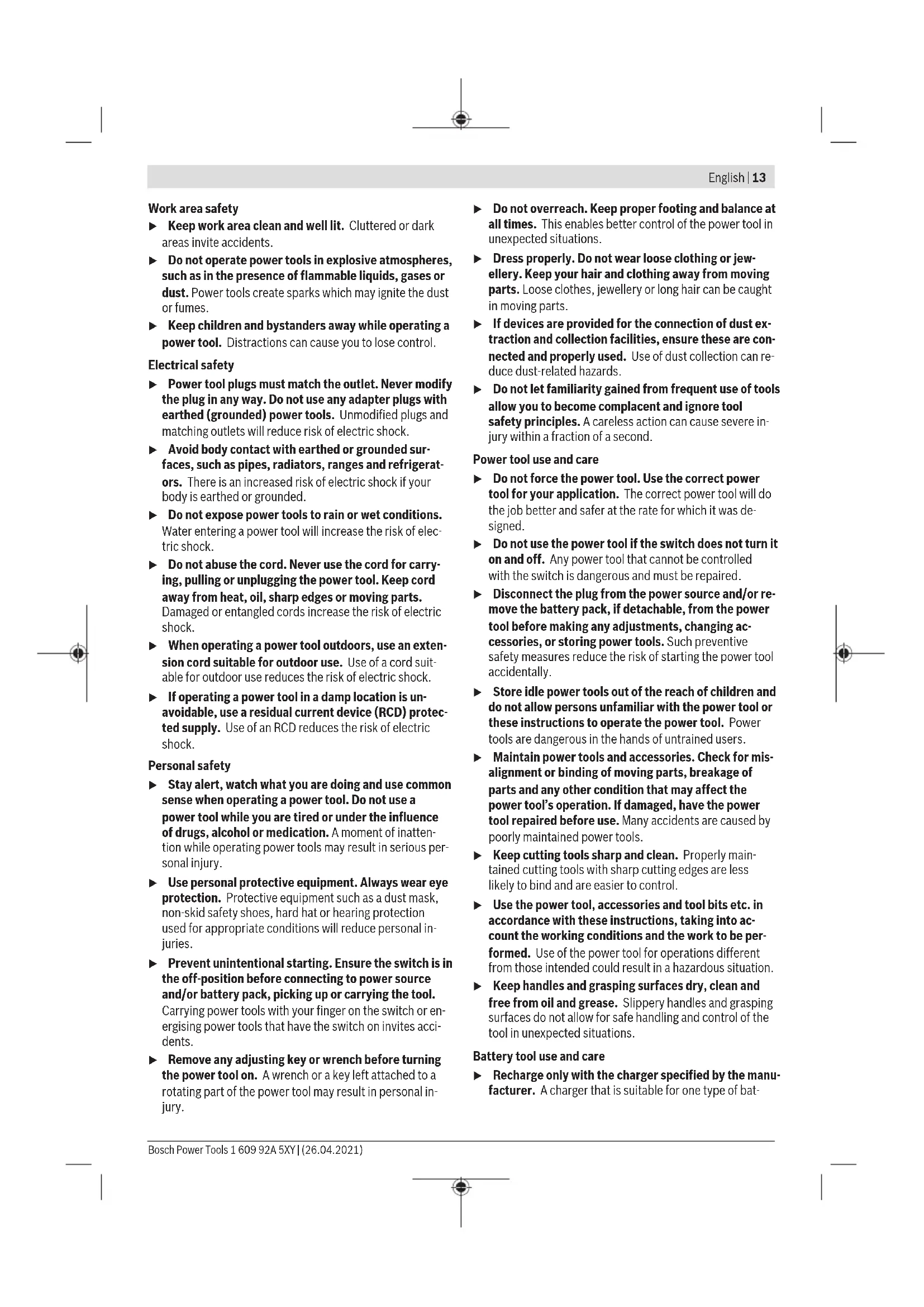
Two identical electric drill press devices with black and gray casing, shown from different angles (no text or symbols visible)natural_image
Technical line drawing of a mechanical device with labeled part (8), no readable text or symbols present.GDR 180-LI
4
Deutsch
Sicherheitshinweise
natural_image
Illustration of hands holding a car interior panel with a numbered arrow indicating step 1 (no text or symbols on the diagram itself)
natural_image
Illustration of hands assembling a mechanical component with a numbered arrow (no text or symbols)www.bosch-pt.com/serviceaddresses
Transport
General Power Tool Safety Warnings
WARNING
Read all safety warnings, instructions, illustrations and specifica-
tions provided with this power tool. Failure to follow all instructions listed below may result in electric shock, fire and/or serious injury.
Save all warnings and instructions for future reference.
The term "power tool" in the warnings refers to your mains-operated (corded) power tool or battery-operated (cordless) power tool.
Work area safety
▶ Keep work area clean and well lit. Cluttered or dark areas invite accidents.
▶ Do not operate power tools in explosive atmospheres, such as in the presence of flammable liquids, gases or dust. Power tools create sparks which may ignite the dust or fumes.
▶ Keep children and bystanders away while operating a power tool. Distractions can cause you to lose control.
Electrical safety
▶ Power tool plugs must match the outlet. Never modify the plug in any way. Do not use any adapter plugs with earthed (grounded) power tools. Unmodified plugs and matching outlets will reduce risk of electric shock.
▶ Avoid body contact with earthed or grounded surfaces, such as pipes, radiators, ranges and refrigerators. There is an increased risk of electric shock if your body is earthed or grounded.
▶ Do not expose power tools to rain or wet conditions. Water entering a power tool will increase the risk of electric shock.
▶ Do not abuse the cord. Never use the cord for carrying, pulling or unplugging the power tool. Keep cord away from heat, oil, sharp edges or moving parts. Damaged or entangled cords increase the risk of electric shock.
▶ When operating a power tool outdoors, use an extension cord suitable for outdoor use. Use of a cord suitable for outdoor use reduces the risk of electric shock.
▶ If operating a power tool in a damp location is unavoidable, use a residual current device (RCD) protected supply. Use of an RCD reduces the risk of electric shock.
Personal safety
▶ Stay alert, watch what you are doing and use common sense when operating a power tool. Do not use a power tool while you are tired or under the influence of drugs, alcohol or medication. A moment of inattention while operating power tools may result in serious personal injury.
▶ Use personal protective equipment. Always wear eye protection. Protective equipment such as a dust mask, non-skid safety shoes, hard hat or hearing protection used for appropriate conditions will reduce personal injuries.
▶ Prevent unintentional starting. Ensure the switch is in the off-position before connecting to power source and/or battery pack, picking up or carrying the tool. Carrying power tools with your finger on the switch or energising power tools that have the switch on invites accidents.
Remove any adjusting key or wrench before turning the power tool on. A wrench or a key left attached to a rotating part of the power tool may result in personal injury.
▶ Do not overreach. Keep proper footing and balance at all times. This enables better control of the power tool in unexpected situations.
▶ Dress properly. Do not wear loose clothing or jewellery. Keep your hair and clothing away from moving parts. Loose clothes, jewellery or long hair can be caught in moving parts.
If devices are provided for the connection of dust extraction and collection facilities, ensure these are connected and properly used. Use of dust collection can reduce dust-related hazards.
▶ Do not let familiarity gained from frequent use of tools allow you to become complacent and ignore tool safety principles. A careless action can cause severe injury within a fraction of a second.
Power tool use and care
▶ Do not force the power tool. Use the correct power tool for your application. The correct power tool will do the job better and safer at the rate for which it was designed.
▶ Do not use the power tool if the switch does not turn it on and off. Any power tool that cannot be controlled with the switch is dangerous and must be repaired.
▶ Disconnect the plug from the power source and/or remove the battery pack, if detachable, from the power tool before making any adjustments, changing accessories, or storing power tools. Such preventive safety measures reduce the risk of starting the power tool accidentally.
▶ Store idle power tools out of the reach of children and do not allow persons unfamiliar with the power tool or these instructions to operate the power tool. Power tools are dangerous in the hands of untrained users.
- Maintain power tools and accessories. Check for misalignment or binding of moving parts, breakage of parts and any other condition that may affect the power tool's operation. If damaged, have the power tool repaired before use. Many accidents are caused by poorly maintained power tools.
▶ Keep cutting tools sharp and clean. Properly maintained cutting tools with sharp cutting edges are less likely to bind and are easier to control.
▶ Use the power tool, accessories and tool bits etc. in accordance with these instructions, taking into account the working conditions and the work to be performed. Use of the power tool for operations different from those intended could result in a hazardous situation.
▶ Keep handles and grasping surfaces dry, clean and free from oil and grease. Slippery handles and grasping surfaces do not allow for safe handling and control of the tool in unexpected situations.
Battery tool use and care
▶ Recharge only with the charger specified by the manufacturer. A charger that is suitable for one type of bat-
14 | English
tery pack may create a risk of fire when used with another battery pack.
▶ Use power tools only with specifically designated battery packs. Use of any other battery packs may create a risk of injury and fire.
▶ When battery pack is not in use, keep it away from other metal objects, like paper clips, coins, keys, nails, screws or other small metal objects, that can make a connection from one terminal to another. Shorting the battery terminals together may cause burns or a fire.
▶ Under abusive conditions, liquid may be ejected from the battery; avoid contact. If contact accidentally occurs, flush with water. If liquid contacts eyes, additionally seek medical help. Liquid ejected from the battery may cause irritation or burns.
▶ Do not use a battery pack or tool that is damaged or modified. Damaged or modified batteries may exhibit unpredictable behaviour resulting in fire, explosion or risk of injury.
▶ Do not expose a battery pack or tool to fire or excessive temperature. Exposure to fire or temperature above 130^ C may cause explosion.
▶ Follow all charging instructions and do not charge the battery pack or tool outside the temperature range specified in the instructions. Charging improperly or at temperatures outside the specified range may damage the battery and increase the risk of fire.
Service
▶ Have your power tool serviced by a qualified repair person using only identical replacement parts. This will ensure that the safety of the power tool is maintained.
▶ Never service damaged battery packs. Service of battery packs should only be performed by the manufacturer or authorized service providers.
Safety Warnings for Impact Wrenches
▶ Hold the power tool by insulated gripping surfaces, when performing an operation where the fastener may contact hidden wiring. Fasteners contacting a "live" wire may make exposed metal parts of the power tool "live" and could give the operator an electric shock.
▶ Use suitable detectors to determine if there are hidden supply lines or contact the local utility company for assistance. Contact with electric cables can cause fire and electric shock. Damaging gas lines can lead to explosion. Breaking water pipes causes property damage.
▶ Hold the power tool securely. When tightening and loosening screws be prepared for temporarily high torque reactions.
- Secure the workpiece. A workpiece clamped with clamping devices or in a vice is held more secure than by hand.
▶ Always wait until the power tool has come to a complete stop before placing it down. The application tool can jam and cause you to lose control of the power tool.
In case of damage and improper use of the battery, vapours may be emitted. The battery can set alight or explode. Ensure the area is well ventilated and seek medical attention should you experience any adverse effects. The vapours may irritate the respiratory system.
▶ Do not open the battery. There is a risk of short-circuiting.
The battery can be damaged by pointed objects such as nails or screwdrivers or by force applied externally. An internal short circuit may occur, causing the battery to burn, smoke, explode or overheat.
▶ Only use the battery with products from the manufacturer. This is the only way in which you can protect the battery against dangerous overload.
Protect the battery against heat, e.g. against continuous intense sunlight, fire, dirt, water and moisture. There is a risk of explosion and short-circuiting.
Product Description and Specifications

Read all the safety and general instructions. Failure to observe the safety and general instructions may result in electric shock, fire and/or serious injury.
Please observe the illustrations at the beginning of this operating manual.
Intended Use
The machine is intended for driving in and loosening screws and bolts as well as for tightening and loosening nuts within the respective range of dimension.
Product Features
The numbering of the product features refers to the diagram of the power tool on the graphics page.
(1) Tool holder
(2) Locking sleeve ^a)
(3) Battery ^a)
(4) Battery release button ^a)
(5) Rotational direction switch
(6) On/off switch
(7) "PowerLight" lamp
(8) Handle (insulated gripping surface)
(9) Screwdriver bit with ball catch ^a)
(10) Universal bit holder ^a)
(11) Screwdriver bit ^a)
(12) Application tool (e.g. screw nut) ^a)
(13) Carbon brushes
(14) Cover cap
a) Accessories shown or described are not included with the product as standard. You can find the complete selection of accessories in our accessories range.
Technical Data
| Cordless impact screwdriver GDR 180-LI GDX 180-LI | ||
| Article number | 3 601 JG5 1.. 3 601 JG5 2.. | |
| Rated voltage V 18 18 | ||
| No-load speed ^A) | min ^-1 | 0-2800 0-2800 |
| Impact rate min | ^-1 | 0-3600 0-3600 |
| Maximum torque, hard screwdriving application according to ISO 5393 | ||
| - 14" internal hexagon ^A) | Nm 160 160 | |
| - ■ 12" Nm - 180 | ||
| Machine screw diameter mm M6-M14 M6-M16 | ||
| Tool holder | ■ 12" | |
| 14" internal hexagon | 14" internal hexagon | |
| Weight according to EPTA-Procedure 01:2014 ^A) | kg 1.7 1.8 | |
| Recommended ambient temperature during charging °C 0 to +35 0 to +35 | ||
| Permitted ambient temperature during operation ^B) and during storage | °C | -20 to +50 |
| Recommended batteries | GBA 18V...ProCORE18V... | |
| Recommended chargers | GAL 18...GAX 18...GAL 36... | |
A) Depends on battery in use
B) Limited performance at temperatures <0^
Noise/Vibration Information
Noise emission values determined according to EN 62841-2-2.
Typically the A-weighted noise level of the power tool is: Sound pressure level 96 dB(A); sound power level 107 dB(A). Uncertainty K = 3 dB.
Wear hearing protection
Total vibration values a_h (triax vector sum) and uncertainty K determined according to EN 62841-2-2:
Tightening screws and nuts of the maximum permitted size: a_n = 9.5 m/s^2 , K = 1.5 m/s^2 .
The vibration level and noise emission value given in these instructions have been measured in accordance with a standardised measuring procedure and may be used to compare power tools. They may also be used for a preliminary estimation of vibration and noise emissions.
The stated vibration level and noise emission value represent the main applications of the power tool. However, if the power tool is used for other applications, with different application tools or is poorly maintained, the vibration level and noise emission value may differ. This may significantly increase the vibration and noise emissions over the total working period.
To estimate vibration and noise emissions accurately, the times when the tool is switched off or when it is running but not actually being used should also be taken into account. This may significantly reduce vibration and noise emissions over the total working period.
Implement additional safety measures to protect the operator from the effects of vibration, such as servicing the power tool and application tools, keeping their hands warm, and organising workflows correctly.
Assembly
▶ Remove the battery from the power tool before carrying out work on the power tool (e.g. maintenance, changing tool, etc.). The battery should also be removed for transport and storage. There is risk of injury from unintentionally pressing the on/off switch.
Charging the Battery
▶ Use only the chargers listed in the technical data. Only these chargers are matched to the lithium-ion battery of your power tool.
Note: The battery is supplied partially charged. To ensure full battery capacity, fully charge the battery in the charger before using your power tool for the first time.
16 | English
The lithium-ion battery can be charged at any time without reducing its service life. Interrupting the charging process does not damage the battery.
The lithium-ion battery is protected against deep discharge by the "Electronic Cell Protection (ECP)". When the battery is discharged, the power tool is switched off by means of a protective circuit: The application tool no longer rotates.
▶ Do not continue to press the On/Off switch after the power tool has automatically switched off. The battery can be damaged.
Follow the instructions on correct disposal.
Removing the battery
The battery (3) is equipped with two locking levels to prevent the battery from falling out when pushing the battery release button (4) unintentionally. As long as the battery is inserted in the power tool, it is held in position by means of a spring.
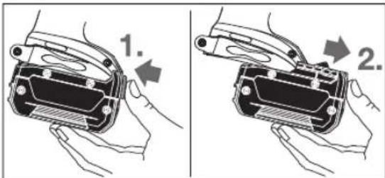
To remove the battery (3), press the release button (4) and pull the battery forward and out of the power tool. Do not use force to do this.
Battery charge indicator
The green LEDs on the battery charge indicator indicate the state of charge of the battery. For safety reasons, it is only possible to check the state of charge when the power tool is not in operation.
Press the button for the battery charge indicator or to show the state of charge. This is also possible when the battery is removed.
If no LED lights up after pressing the button for the battery charge indicator, then the battery is defective and must be replaced.
Battery model GBA 18V...

LEDs Capacity
3× continuous green light 60-100%
2× continuous green light 30-60%
1× continuous green light 5–30%
1× flashing green light 0–5 %
Battery model ProCORE18V...
LEDs Capacity
| 5× continuous green light 80-100% |
| 4× continuous green light 60-80% |
| 3× continuous green light 40-60% |
| 2× continuous green light 20-40% |
| 1× continuous green light 5-20% |
| 1× flashing green light 0-5% |
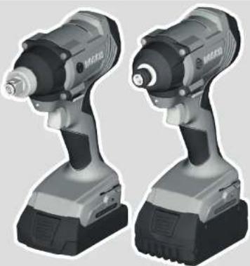
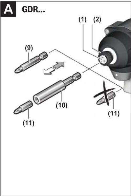
Changing the Tool (see figures A and B)
Remove the battery from the power tool before carrying out work on the power tool (e.g. maintenance, changing tool, etc.). The battery should also be removed for transport and storage. There is risk of injury from unintentionally pressing the on/off switch.
When working with an application tool, ensure that the application tool is connected securely to the tool holder. If the application tool is not securely connected to the tool holder, it can come off during operation.
Inserting
GDR 180-LI:
Pull the locking sleeve (2) forward, guide the application tool (1) into the tool holder up to the stop and release the locking sleeve (2) to lock the application tool.
Only use screwdriver bits with ball catch (9) (DIN 3126-E6.3). Other screwdriver bits (11) can be inserted using a universal bit holder with ball catch (10).
GDX 180-LI:
Slide the application tool (12) onto the square drive of the tool holder (1).
Due to the way the system operates, the application tool (12) will move around slightly in the tool holder (1); this has no effect on the function/safety.
Removing
Pull the locking sleeve (2) forward and remove the application tool.
Operation
Method of Operation
The tool holder (1) (with the application tool) is driven by an electric motor via a gear and impact mechanism.
The working procedure is divided into two phases:
Screwing in and tightening (impact mechanism in action). The impact mechanism is activated as soon as the screwed connection runs tight and load is therefore put on the motor. The impact mechanism then converts the power of the motor to steady rotary impacts. When loosening screws or nuts, the process is reversed.
Starting Operation
Inserting the Battery
Set the rotational direction switch (5) to the centre position to protect the power tool from being switched on accidentally.
Push the charged battery (3) into the base of the power tool from the front until the battery is securely locked.
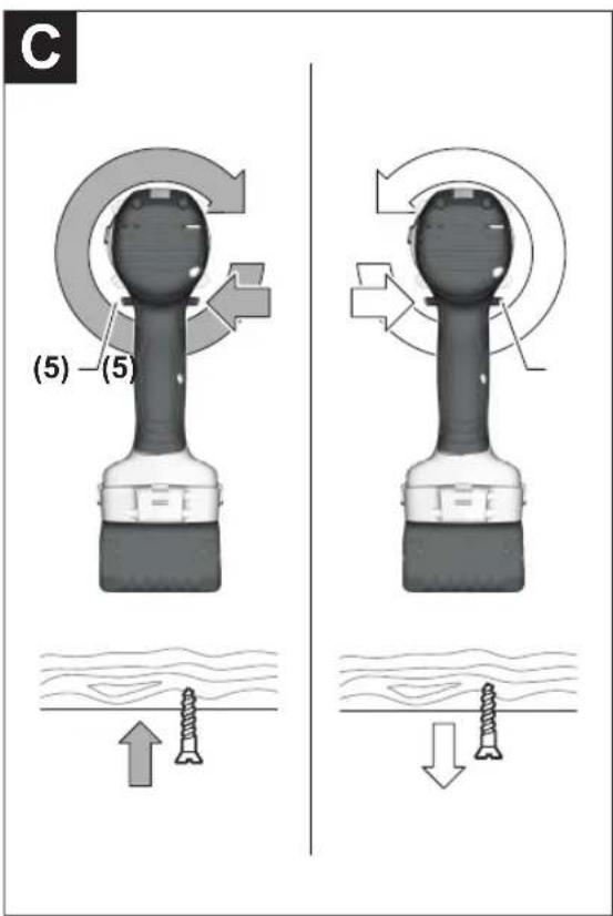
Set the rotational direction (see figure C)
The rotational direction switch (5) is used to change the rotational direction of the power tool. However, this is not possible while the on/off switch (6) is being pressed.
Right rotation: To drive in screws and tighten nuts, press the rotational direction switch (5) through to the left stop.
Left Rotation: To loosen and unscrew screws and nuts, press the rotational direction switch (5) through to the right stop.
Switching on/off
To start the power tool, press and hold the on/off switch (6).
The lamp (7) lights up when the on/off switch (6) is lightly or fully pressed, meaning that the work area is illuminated in poor lighting conditions.
To switch off the power tool, release the on/off switch (6).
Adjusting the Speed
You can adjust the speed of the power tool when it is on by pressing in the on/off switch (6) to varying extents.
A light pressure on the on/off switch (6) results in a low rotational speed. Increased pressure on the switch causes an increase in speed.
Practical advice
▶ Only apply the power tool to the screw/nut when the tool is switched off. Rotating tool inserts can slip off.
The torque depends on the impact duration. The maximum achieved torque results from the sum of all individual torques achieved through impact. Maximum torque is achieved after an impact duration of 6–10 seconds. After this duration, the tightening torque increases only minimally. The impact duration is to be determined for each required tightening torque. The tightening torque actually achieved should always be checked with a torque wrench.
Screw applications with hard, spring-loaded or soft seats When the achieved torques in an impact series are measured during a test and transferred onto a diagram, the result is the curve of a torque characteristic. The height of the curve corresponds to the maximum achievable torque, and the steepness indicates the duration in which this is achieved.
A torque characteristic depends on the following factors:
– Strength properties of the screws/nuts
- Type of backing (washer, disc spring, seal)
– Strength properties of the material being screwed/bolted together
– Lubrication conditions at the screw/bolt connection
Consequently, the following applies in each case:
- A hard seat is used for metal-to-metal screw applications that use washers. After a relatively short impact duration, the maximum torque is achieved (steep characteristic curve). An unnecessarily long impact duration only causes damage to the machine.
- A spring-loaded seat is used for metal-to-metal screw applications that use spring washers, disc springs, studs or screws/nuts with conical seats. It is also called a spring-loaded seat when extensions are used.
- A soft seat is used for screw applications of e.g. metal on wood or screw applications that use lead washers or fibre washers as backing.
For a spring-loaded seat, as well as for a soft seat, the maximum tightening torque is lower than for a hard seat. A much longer impact duration is also required.
Guide values for maximum screw tightening torques
Figures given in Nm; calculated from the tensional cross-section; utilization of the yield point: 90% (with friction coefficient _total = 0.12 ). As a control measure, always check the tightening torque with a torque wrench.
| Property Classes according to DIN 267 | Standard Screws/Bolts High-strength Bolts | ||||||||||
| 3.6 | 4.6 | 5.6 | 4.8 | 6.6 | 5.8 | 6.8 | 6.9 | 8.8 | 10.9 | 12.9 | |
| M6 | 2.71 | 3.61 | 4.52 | 4.8 | 5.42 | 6.02 | 7.22 | 8.13 | 9.7 | 13.6 | 16.2 |
| M8 | 6.57 | 8.7 | 11 | 11.6 | 13.1 | 14.6 | 17.5 | 19.7 | 23 | 33 | 39 |
| M10 | 13 | 17.5 | 22 | 23 | 26 | 29 | 35 | 39 | 47 | 65 | 78 |
| M12 | 22.6 | 30 | 37.6 | 40 | 45 | 50 | 60 | 67 | 80 | 113 | 135 |
| M14 | 36 | 48 | 60 | 65 | 72 | 79 | 95 | 107 | 130 | 180 | 215 |
| M16 | 55 | 73 | 92 | 98 | 110 | 122 | 147 | 165 | 196 | 275 | 330 |
Tips
Before screwing larger, longer screws into hard materials, it is advisable to pre-drill a pilot hole with the core diameter of the thread to approx. 2/3 of the screw length.
Note: Ensure that no metal particles enter the power tool.
Belt clip
You can use the belt clip to hang the power tool on a belt, for example. You then have both hands free and the power tool is always at hand.
18 | English
Recommendations for Optimal Handling of the Battery
Protect the battery against moisture and water.
Only store the battery within a temperature range of -20 to 50 °C. Do not leave the battery in your car in the summer, for example.
Occasionally clean the ventilation slots on the battery using a soft brush that is clean and dry.
A significantly reduced operating time after charging indicates that the battery has deteriorated and must be replaced. Follow the instructions on correct disposal.
Maintenance and Service
Maintenance and Cleaning
Remove the battery from the power tool before carrying out work on the power tool (e.g. maintenance, changing tool, etc.). The battery should also be removed for transport and storage. There is risk of injury from unintentionally pressing the on/off switch.
▶ To ensure safe and efficient operation, always keep the power tool and the ventilation slots clean.
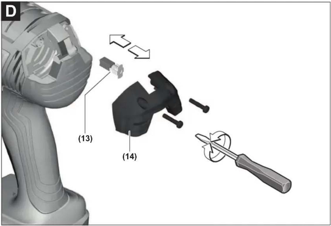
Replacing the carbon brushes (see figure D)
Check the length of the carbon brushes around every 2–3 months and replace both carbon brushes if required.
Never replace only a single carbon brush.
Note: Only use carbon brushes supplied by Bosch and intended specifically for your product.
- Unscrew the caps (14) using a suitable screwdriver.
- Replace the spring-loaded carbon brushes (13) and screw the caps back on.
After-Sales Service and Application Service
Our after-sales service responds to your questions concerning maintenance and repair of your product as well as spare parts. You can find explosion drawings and information on spare parts at: www.bosch-pt.com
The Bosch product use advice team will be happy to help you with any questions about our products and their accessories.
In all correspondence and spare parts orders, please always include the 10-digit article number given on the nameplate of the product.
Great Britain
Robert Bosch Ltd. (B.S.C.)
P.O. Box 98
Broadwater Park
North Orbital Road
Denham Uxbridge
UB 9 5HJ
At www.bosch-pt.co.uk you can order spare parts or arrange the collection of a product in need of servicing or repair.
Tel. Service: (0344) 7360109
E-Mail: boschservicecentre@bosch.com
You can find further service addresses at:
www.bosch-pt.com/serviceaddresses
Transport
The contained lithium-ion batteries are subject to the Dangerous Goods Legislation requirements. The batteries are suitable for road-transport by the user without further restrictions.
When shipping by third parties (e.g.: by air transport or forwarding agency), special requirements on packaging and labelling must be observed. For preparation of the item being shipped, consulting an expert for hazardous material is required.
Dispatch battery packs only when the housing is undamaged. Tape or mask off open contacts and pack up the battery in such a manner that it cannot move around in the packaging. Please also observe the possibility of more detailed national regulations.
Disposal

Power tools, rechargeable batteries, accessories and packaging should be sorted for environmental-friendly recycling.
Do not dispose of power tools and batteries/re-chargeable batteries into household waste!

Only for EU countries:
According to the Directive 2012/19/EU, power tools that are no longer usable, and according to the Directive 2006/66/EC, defective or used battery packs/batteries, must be collected separately and disposed of in an environmentally correct manner.
Battery packs/batteries:
Li-ion:
Please observe the notes in the section on transport (see "Transport", page 18).
Maintenance and Cleaning
Remove the battery from the power tool before carrying out work on the power tool (e.g. maintenance, changing tool, etc.). The battery should also be removed for transport and storage. There is risk of injury from unintentionally pressing the on/off switch.
▶ To ensure safe and efficient operation, always keep the power tool and the ventilation slots clean.
Replacing the carbon brushes (see figure D)
Check the length of the carbon brushes around every 2–3 months and replace both carbon brushes if required. Never replace only a single carbon brush.
Note: Only use carbon brushes supplied by Bosch and intended specifically for your product.
- Unscrew the caps (14) using a suitable screwdriver.
- Replace the spring-loaded carbon brushes (13) and screw the caps back on.
Français
Robert Bosch (France) S.A.S.
www.bosch-pt.com/serviceaddresses
Transport
www.bosch-pt.com/serviceaddresses
Transporte
natural_image
Illustration of hands installing or adjusting a device component with a numbered arrow (no text or symbols present)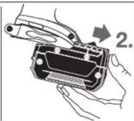
natural_image
Illustration of hands assembling a mechanical component with an arrow indicating step 2 (no text or symbols present)www.bosch-pt.com/serviceaddresses
Transporte
www.bosch-pt.com/serviceaddresses
Trasporto
www.bosch-pt.com/serviceaddresses
Vervoer
- Skruernes/møtrikkernes fasthed
- Underlagets art (skive, tallerkenfjeder, pakning)
Bosch Service Center
Telegrafvej 3
2750 Ballerup
På www.bosch-pt.dk kan der online bestilles reservedele eller oprettes en reparations ordre.
Tlf. Service Center: 44898855
Fax: 44898755
E-Mail: vaerktoej@dk.bosch.com
www.bosch-pt.com/serviceaddresses
Transport
Bosch Service Center
Telegrafvej 3
2750 Ballerup
Danmark
Tel.: (08) 7501820 (inom Sverige)
Fax: (011) 187691
www.bosch-pt.com/serviceaddresses
Transport
www.bosch-pt.com/serviceaddresses
Transport
www.bosch-pt.com/serviceaddresses
Kuljetus
www.bosch-pt.com/serviceaddresses
Μεταφορά
www.bosch-pt.com/serviceaddresses
Nakliye
Robert Bosch Sp. z o.o.
www.bosch-pt.com/serviceaddresses
Transport
Bosch Service Center PT
K Vápence 1621/16
692 01 Mikulov
www.bosch-pt.com/serviceaddresses
Přeprava
www.bosch-pt.com/serviceaddresses
Transport
www.bosch-pt.com/serviceaddresses
Szállítás
www.bosch-pt.com/serviceaddresses
www.bosch-pt.com/serviceaddresses
Транспортування
www.bosch-pt.com/serviceaddresses
Service scule electrice
Strada Horia Măcelariu Nr. 30-34, sector 1
013937 Bucureşti
www.bosch-pt.com/serviceaddresses
Transport
Service scule electrice
Strada Horia Măcelariu Nr. 30-34, sector 1
013937 Bucureşti, România
www.bosch-pt.com/bg/bg/
www.bosch-pt.com/serviceaddresses
Транспортиране
natural_image
Illustration of hands installing or adjusting a device component with a numbered arrow (no text or symbols present)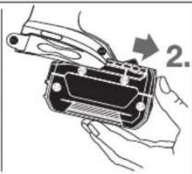
natural_image
Illustration of hands holding a device with a handle and internal components, no text or symbols presentwww.bosch-pt.com/serviceaddresses
Транспорт
www.bosch-pt.com/serviceaddresses
Transport
Akumulatorske baterije koje sadrže litijum jon podležu zahtevima prava o opasnim materijama. Akumulatorske baterije korisnik može transportovati na drumu bez drugih pakovanja.
Kod slanja preko trećih lica (na primer vazdušnih transportom ili špedicijom) mora se obratiti pažnja na posebne zahteve u pogledu pakovanja i označavanja. Tada se kod pripreme paketa za slanje mora pozvati stručnjak za opasne materije.
Akumulatorske baterije šaljite samo ako kućište nije oštećeno. Odlepite otvorene kontakte i upakujte akumulatorsku bateriju tako, da se ne pokreće u paketu. Molimo da obratite pažnju na eventualne dalje nationalne propise.
Uklanjanje dubreta

Električne alate, akumulacione baterije, pribor i pakovanja treba predati na reciklažu koja je u skladu sa zaštitom životne sredine.

Ne bacajte električne alate i akumulatore/baterije u kućno djubre!
Samo za EU-zemlje:
Prema evropskoj smernici 2012/19/EU električni alati koji su neupotrebljivi, a prema evropskoj smernici 2006/66/EC ni akumulatori/baterije koji su u kvaru ili istrošeni, ne moraju
172 | Slovenščina
više da se odvojeno sakupljaju i odvoze na reciklažu koja odgovara zaštiti čovekove sredine.
www.bosch-pt.com/serviceaddresses
Transport
www.bosch-pt.com/serviceaddresses
Transport
Litij-ionske aku-baterije podliježu zakonu o transportu opasnih tvari. Korisnik bez ikakvih preduvjeta može transportirati aku-baterije cestovnim transportom.
www.bosch-pt.com/serviceaddresses
Transport
www.bosch-pt.com/serviceaddresses
Transportēšana
natural_image
Illustration of hands installing or adjusting a device component with a numbered arrow (no text or symbols present)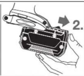
natural_image
Illustration of hands holding a device with a handle and a numbered arrow indicating step 2 (no text or symbols present)www.bosch-pt.com/serviceaddresses
Transportavimas
www.bosch-pt.com/serviceaddresses
운반
ال Ratings Impact: What is the correct.
Robert Bosch Morocco SARL
53.شارع الملازم محمد محرود
20300 aldar البضاء
www.bosch-pt.com/serviceaddresses
النقل
natural_image
Isometric line drawing of a mechanical housing or enclosure with internal compartments and structural elements (no text or symbols)GDR 18 V-LI
2608438007
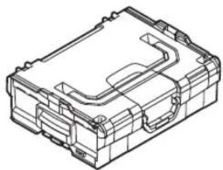
natural_image
Isometric line drawing of a mechanical housing or enclosure component (no text or symbols)L-BOXX 136
1 600 A00 1RR
CE
|
| de | EU-Konformitätserklärung | Wir erklären in alleiniger Verantwortung, dass die genannten Produkte allen einschlägigen Bestimmungen der nachfolgend aufgeführten Richtlinien und Verordnungen entsprechen und mit folgenden Normen übereinstimmen. Technische Unterlagen bei: * | |
| Akku-Schlagschrauber | Sachnummer | ||
| en | EU Declaration of Conformity | We declare under our sole responsibility that the stated products comply with all applicable provisions of the directives and regulations listed below and are in conformity with the following standards.Technical file at: * | |
| Cordless impact screwdriver | Article number | ||
| fr | Déclaration de conformité UE | Nous déclarons sous notre propre responsabilité que les produits décrits sont en conformité avec les directives, règlements normatifs et normes énumérés ci-dessous.Dossier technique auprès de : * | |
| Visseuse à chocs sans fil | N° d'article | ||
| es | Declaración de conformidad UE | Declaramos bajo nuestra exclusiva responsabilidad, que los productos nombrados cumplen con todas las disposiciones correspondientes de las Directivas y los Reglamentos mencionados a continuación y están en conformidad con las siguientes normas.Documentos técnicos de: * | |
| Atornilladora de impacto accionada por acumulador | N° de artículo | ||
| pt | Declaração de Conformidade UE | Declaramos sob nossa exclusiva responsabilidade que os produtos mencionados cumprem todas as disposições e os regulamentos indicados e estão em conformidade com as seguintes normas.Documentação técnica pertencente à: * | |
| Aparafusadora de percussão sem fio | N.° do produto | ||
| it | Dichiarazione di conformità UE | Dichiariamo sotto la nostra piena responsabilità che i prodotti indicati sono conformi a tutte le disposizioni pertinenti delle Direttive e dei Regolamenti elencati di seguito, nonché alle seguenti Normative.Documentazione Tecnica presso: * | |
| Avvitatore a percussione a batteria | Codice prodotto | ||
| nl | EU-conformiteitsverklaring | Wij verklaren op eigen verantwoordelijkheid dat de genoemde producten voldoen aan alle desbetreffende bepalingen van de hierna genoemde richtlijnen en verordeningen en overeenstemmen met de volgende normen.Technisch dossier bij: * | |
| Accuslagmoeraan zetter | Productnummer | ||
| da | EU-overensstemmelseserklæring | Vi erklærer som eneansvarlige, at det beskrevne produkt er i overensstemmelse med alle gældende bestemmelser i følgende direktiver og forordninger og opfylder følgende standarder.Tekniske bilag ved: * | |
| Akku-slagnøgle | Typenummer | ||
| sv | EU-konformitetsförklaring | Vi förklarar under eget ansvar att de nämnda produkterna uppfyller kraven i alla gällande bestämmelser i de nedan angivna direktiven och förordningarnas och att de stämmer överens med följande normer.Teknisk dokumentation: * | |
| Sladdlös slagskruvdragare | Produktnummer | ||
| no | EU-samsvarserklæring | Vi erklærer under eneansvar at de nevnte produktene er i overensstemmelse med alle relevante bestemmelser i direktivene og forordningene nedenfor og med følgende standarder.Teknisk dokumentasjon hos: * | |
| Batteridrevet slagtrekker | Produktnummer | ||
| fi | EU-vaatimustenmukaisuusvakuutus | Vakuutamme täten, että mainitut tuotteet vastaavat kaikkia seuraavien direktiivien ja asetusten asiaankuuluvia vaatimuksia ja ovat seuraavien standardien vaatimusten mukaisia.Tekniset asiakirjat saatavana: * | |
| Akkuiskuruuivn äännin | Tuotenumero | ||
| el | Δήλωση πιστότητας EE | Δηλώνουμε με αποκλειστική μας ευθύνη, ότι τα αναφερόμενα προϊόντα αντιστοιχούν σε όλες τις σχετικές διατάξεις των πιο κάτω αναφερόμενων οδηγιών και κανονισμών και ταυτίζονται με τα ακόλουθα πρότυπα.Tεχνικά έγγραφα στη: * | |
| Μπουλονόκλειδο μπαταρίας | Αριθμός ευρετηρίου | ||
| tr | AB Uygunluk beyani | Tek sorumlu olarak, tanimlanan ürünün aşağıdaki yönetmelik ve direktiflerin geçerli bütün hükümlerine ve aşağıdaki standartlara uygun olduğunu beyan ederiz.Teknik belgelerin bulunduğu yer: * | |
| Akülü darbeli somun sıkma makinesi | Ürün kodu | ||
| II | CE | ||
| pl | Deklaracja zgodności UE | Oświadczamy z pełną odpowiedzialnością, że niniejsze produktyodpowiadają wszystkim wymaganiom poniżej wyszczególnionych dyrektyw irozporządzeń, oraz że są zgodne z następującymi normami.Dokumentacja techniczna:* | |
| Akumulatorowy klucz udarowy | Numer katalogowy | ||
| cs | EU prohlásení oshodě | Prohlašujeme na výhradní zodpovědnost, že uvedený výrobek splňujevšechna příslušná ustanovení níže uvedených smérnic anařízení aje vsouladusnásledujícími normami:Technické podklady u:* | |
| Akumulátorový rázový utahovák | Objednací číslo | ||
| sk | EÚ vyhlásenie ozhode | Vyhlasujeme na výhradní zodpovednosť, že uvedený výrobok splňa všetkypríslušné ustanovenia nižšie uvedených smerníc anariadení aje vsúladesnasledujícími normami:Technické podklady má spoločnosť:* | |
| Akumulátorový rázový skrutkovač | Vecné číslo | ||
| hu | EU konformitási nyilatkozat | Egyedüli felelőséggel kijelentjük, hogy a megnevezett termékek megfelelnekaz alábbiakban felsorolásra kerülő irányelvek és rendeletek valamennyiidevágó előírásainak és megfelelnek a következő szabványoknak.Műszaki dokumentumok megőrzési pontja:* | |
| Akkus ütvefúró | Cikkszám | ||
| ru | Заявление о соответствии EC | Мы заявляем под нашу единоличную ответственность, что названныепродукты соответствуют всем действующим предписаниямнижеуказанных директив и распоряжений, а также нижеуказанныхнорм.Техническая документация хранится y:* | |
| Аккумуляторный гайковерт ударногодействия | Tоварный No | ||
| uk | Заява про відповідність ЄС | Мизаявляємо під нашу одноособову відповідальність, що названівироби відповідають усім чинним положенням нищеозначених директиві розпоряджень, а також нижчеозначеним нормам.Технічна документація зберігається y:* | |
| Акумуляторний ударний гвинтоверт | Tоварний номер | ||
| kk | EO сәйкестік мағлумдамасы | Өз жауапкершілікпен біз аталған өнімдер теменде жзылғандиректикалар мен жарлықтардың тиісті қағидаларына сәйкестігін жәнетемендері нормаларға сай екенін білдіреміз.Техникалық құжаттар:* | |
| Аккумуляторлық Өнім нөміріқағатынбураушш | |||
| ro | Declarație de conformitate UE | Declarăm pe proprie răspundere că produsele mentionate corespundtuturor dispozițiilor relevante ale directivelor și reglementărilor enumerate încele ce urmează și sunt în conformitate cu următoarele standarde.Documentație tehnică la:* | |
| Mașină de înșurubat cu impact cu acumulator | Număr de identificare | ||
| bg | ЕС декларация за съответствие | С пълна отговорностние декларираме, че посочените продуктиотговарят на всички валидни изисквания на директивите и разпоредбипо-долу и съответства на следните стандарти.Техническа документация при:* | |
| Акумулаторен ударен винтоверт | Каталожен номер | ||
| mk | EU-Изјава за сообразност | Со целосна одговорност изјавуваме, дека опишаните производи се всогласност со сите релевантни одредби на следните регулативи ипрописи и се во согласност со следните норми.Техничка документација кaj:* | |
| Батериски ударен одвртувач | Број на дел/артикл | ||
| sr | EU-izjava o usaglašenosti | Na sopstvenu odgovornost izjavljujemo, da navedeni proizvodi odgovarajusvim dotičnim odredbama naknadno navedenih smernica u uredaba i da su uskladu sa sledećim standardima.Tehnička dokumentacija kod:* | |
| Akumulatorski udarni odvrtač | Broj predmeta | ||
| sl | Izjava o skladnosti EU | Izjavljamo pod izključno odgovornostjo, da je omenjen izdelek v skladu zvsemi relevantnimi določili direktiv in uredb ter ustreza naslednjimstandardom.Tehnična dokumentacija pri:* | |
| Akumulatorski udarni vijačnik | Številka artikla | ||
| hr | EU izjava o sukladnosti | Pod punom odgovornošću izjavljujemo da navedeni proizvodi odgovarajusvim relevantnim odredbama direktiva i propisima navedenima u nastavku i | |
CE
III
| Akumulatorski udarni stezač | Kataloški br. da su sukladni sa sljedećim normama.Tehnička dokumentacija se može dobiti kod: * | ||
| et | EL-vastavusdeklaratsioon | Kinnitame ainuvastutajatena, et nimetatud tooted vastavad järgnevalt loetletud direktiivide ja määruste köikidele asjaomastele nõuetele ja on kooskõlas järgmiste normidega.Tehnilised dokumendid saadaval: * | |
| Aku- lõökkruvikeeraja | Tootenumber | ||
| lv | Deklarácija par atbilstibu ES standartiem | Mës ar pilnu atbildibu paziņojam, ka šeit aplūkotie izstrādājumi atbilst visiem tālāk minētajās direktivās un rīkojumos ietvertajām saistošajām nostādnēm, kā arī sekojošiem standartiem.Tehniskā dokumentācija no: * | |
| Akumulatora triecienskrūvgrie zis | Izstrādājuma numurs | ||
| lt | ES atitikties deklaracija | Atsakingai pareiškiame, kad išvardyti gaminiai atitinka visus privalomus žemiau nurodytų direktyvų ir reglamentų reikalavimus ir šiuos standartus.Techninė dokumentacija saugoma: * | |
| Akumuliatorinis smūginis suktuvas | Gaminio numeris | ||
| GDR 180-LI | 3 601 JG5 1.. | 2006/42/EC EN 62841-1:20152014/30/EU EN 62841-2-2:20142011/65/EU EN 55014-1:2017+A11:2020EN 55014-2:2015EN IEC 63000:2018 | |
| GDX 180-LI | 3 601 JG5 2.. | ||
| * Robert Bosch Power Tools GmbH (PT/ECS)70538 StuttgartGERMANY | |||
| Henk Becker Helmut HeinzelmannChairman of Executive Head of Product CertificationManagementjvejse i.v.kwRobert Bosch Power Tools GmbH, 70538 Stuttgart, GERMANYStuttgart, 29.06.2020 | |||