
Dtect 150 SV Professional - Detector BOSCH - Free user manual and instructions
Find the device manual for free Dtect 150 SV Professional BOSCH in PDF.
| Brand | Bosch |
| Model | Dtect 150 SV Professional |
| Product type | Universal detector (detection of objects in walls, ceilings, floors) |
| Dimensions (L × W × H) | 220 × 97 × 120 mm |
| Weight | 0.65 kg (according to EPTA Procedure 01:2014) |
| Power supply | 4 LR6 (AA) 1.5 V batteries or HR6 (AA) 1.2 V rechargeable batteries; battery life approx. 5 h (batteries) / 7 h (rechargeable batteries 2500 mAh) |
| Operating temperature range | -10 °C to +50 °C |
| Storage temperature | -20 °C to +70 °C |
| Protection rating | IP 54 (dust and splash water protection) |
| Sensors | Radar (2200-5500 MHz) and inductive (5.9-6.1 kHz) |
| Object center measurement accuracy | ±5 mm |
| Displayed depth accuracy (dry concrete) | ±5 mm |
| Displayed depth accuracy (damp concrete) | ±10 mm |
| Minimum distance between two adjacent objects | 40 mm |
| Operating modes | Standard, Damp concrete, 8 cm, 15 cm, Metal/water pipes, Wood/drywall, Intense signal, Signal for all materials |
| Main functions | Detection of metals, wood, plastic, live cables; depth and type display; audible and visual signal (LED) |
| Maintenance and cleaning | Clean with a soft, dry cloth; do not immerse; keep the maintenance flap closed |
| Safety | Instructions: do not use in explosive atmosphere; check other sources before drilling; protection against moisture |
| Spare parts and repairability | Parts available via Bosch; repair only by authorized service; do not open the maintenance flap |
| General information | Compliant with directive 2014/53/EU; declaration of conformity available online |
Frequently Asked Questions - Dtect 150 SV Professional BOSCH
User questions about Dtect 150 SV Professional BOSCH
0 question about this device. Answer the ones you know or ask your own.
Ask a new question about this device
Download the instructions for your Detector in PDF format for free! Find your manual Dtect 150 SV Professional - BOSCH and take your electronic device back in hand. On this page are published all the documents necessary for the use of your device. Dtect 150 SV Professional by BOSCH.
USER MANUAL Dtect 150 SV Professional BOSCH
D-TECT 150 SV Professional


Robert Bosch Power Tools GmbH
70538 Stuttgart
GERMANY
www.bosch-pt.com
160992A4G1(2018.08)1/252

1609 92A 4G1

BOSCH
de Originalbetriebsanleitung
en Originalinstructions
fr notice originale
es Vual original
pt Manual original
It Istruzioni originali
nGorsponkelijke gebrusssaanwijzng
da Original brugsanvising
sv Bruksanvisning original
no Original driftsinstruks
fi Alkuperaisotbject
ellquarumoosyuyu x
Original lset metalat
pInstrukturaorynalna
Pvodni novk poutwnl
Povodni naedn pauiitic
huEredei hasnaliutas
ruOpHHAnHHe pyKoBO
AKCTNYATAHU
ukOpinaiaHcpyku3
eKcNyatai
kk aananaHy pckayneFbHbH
TNNHCKACH
roInstruetioni originale
bgOpnnnnaHnHctyKpn
mkOprrnnaio ynarcgoa pabota
sOrinalineuputstya zaraad
1 Lcima nayodila
hr Originaln uput zarad
et Alguparane kasutusuhend
Instacias originalaada
Original Instruksi.
ar (L) (L)
fa 1al(5niml a)i
Deutsch. .Seite 7
English Page 14
Francais.. Page 22
Espanol . Pagina 30
Portugues.. Pagina 39
Italiano . 47
Nederlands.. 55
Dansk. Side 63
Svensk. Sidan 70
Norsk. Side 77
Suomi .Sivu 84
EAAyivka. 2eAia91
Türkce.. Sayfa 99
Polski Strona 107
Cestina. Stranka 115
Slovencina Stranka 123
Magyar .Oldal 130
Pycckn. .. 138
YkpaIHcbKa .........CtoPiHa 147
Kaazak. Ser 155
Romana.. .Pagina 164
Блгарский ... .. .. .. .. .. .. .. .. .. .. .. .. .. .. .. .. .. .. .. .. .. .. .. .. .. .. .. .. .. .. .. .. .. .. .. .. .. .. .. .. .. .. .. .. .. .. .. .. ... ... ... ... ... ... ... ... ... ... ... ... ... ... ... ... ... ... ... ... ... ... ... ... ... ... ... ... ... ... ... ... ... ... ... ... ... ... ... ... ... ... ... ... ... ... ... ... ... ... ... ... ... ... ... ... ... ... ... ... ... ... ... ... ... ... ... ... ... ... ... ... ... ... ... ... ... . .... .... .... .... .... .... .... .... .... .... .... .... .... .... .... .... .... .... .... .... .... .... .... .... .... .... .... .... .... .... .... .... .... .... .... .... .... .... .... .... .... .... .... .... .... .... .... .... .... .... .... ......
MaKeDoHcN. CtpaHua 180
Srpski Strana 188
Slovenscina Stran 196
Hrvatski. .Stranica 203
Eesti. Lehekulg 211
All instructions must be read and observed. The safeguards integrated into the measuring tool may be compromised if the measuring tool is not used in accordance with these
instructions. STORE THESE INSTRUCTIONS IN A SAFE PLACE.
Have the measuring tool serviced only by a qualified specialist using only original replacement parts. This will ensure that the safety of the measuring tool is maintained.
Do not use the measuring tool in explosive atmospheres which contain flammable liquids, gases or dust. Sparks may be produced inside the measuring tool, which can ignite dust or fumes.
The measuring tool may not be 100% accurate for technological reasons. To eliminate hazards, familiarise yourself with further sources of information, such as building plans and photographs taken during construction, etc. before carrying out any drilling, sawing or routing work on walls, ceilings or floors. The accuracy of the measuring tool may be affected by environmental influences, such the level of humidity or there being other electronic devices nearby. The structure and condition of the walls (e.g. damp, building materials containing metal, electrically conductive wallpaper, insulating materials, tiles) and the number, type, size and position of the objects may distort the measuring results.
Product Description and Specifications
Please observe the illustrations at the beginning of this oper-
ating manual.
Intended use
The measuring tool is intended for the detection of objects in walls, ceilings and floors. Depending on the material and condition of the base material, it is possible to detect metal objects, wooden beams, plastic pipes, conductors and cables. The object depth from the nearest edge of each of the detected objects is determined.
The measuring tool complies with the limits specified in EN 302435. On this basis, clarification is required as to whether the measuring tool can be used in places such as hospitals, nuclear power plants and in the vicinity of airports and mobile phone base stations.
The measuring tool is suitable for indoor and outdoor use.
Product features
The numbering of the product features shown refers to the illustration of the measuring tool on the graphic page.
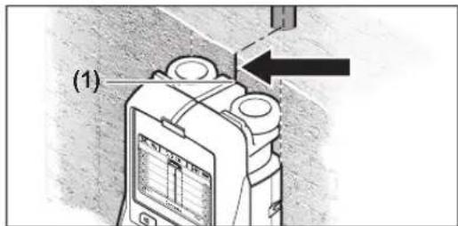
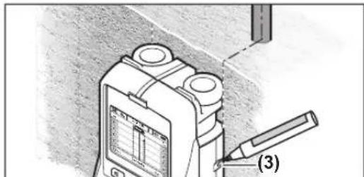
(1) Top marking aid
(2) Wheel
(3) Left and right marking aids
(4) Battery compartment cover
(5) Locking mechanism of the battery compartment cover
(6) Handle
(7) Maintenance flap
(8) Serial number
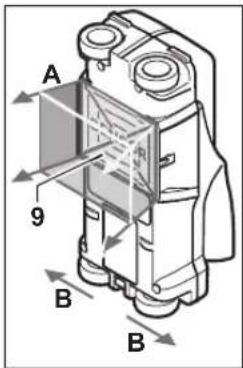
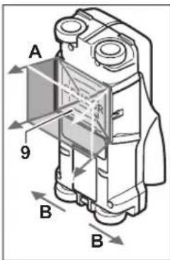
(9) Sensor area
(10) Right select button
(11) Start button
(12) Left select button
(13) Audio signal button
(14) Setup button
(15) On/off button
(16) Display
(17) LED
(18) Protective bag
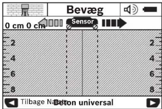
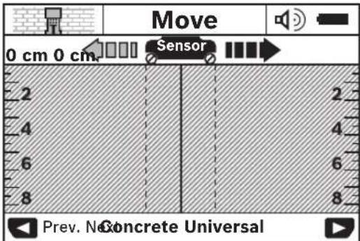
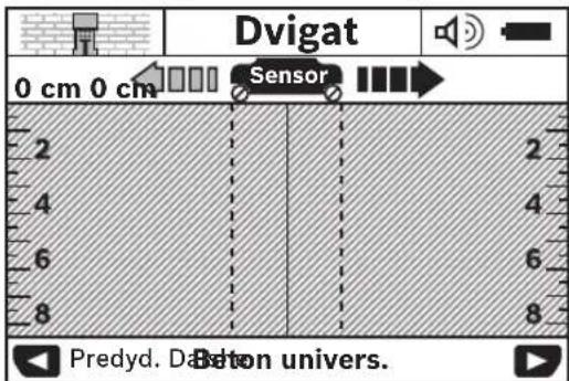
Display elements
(a) Audio signal indicator
(b) Battery indicator
(c) Display for sensor range
(d) Area already checked
(e) Measuring scale for object depth
(f) Area not yet checked
(g) Outer edges, to be marked left and right via the marking aid (3)
(h) Operating mode indicator
(i) Black: Detected object is within the sensor range
(j) Grey: Detected object is outside the sensor range
(k) Centre line, corresponds with the marking aid (1)
(I) Object depth indicator
(m) Object material indicator
(n) Live cable indicator
Technical data
| Universal detector D-rect 150 SV | |
| Article number | 3601 K10 008 |
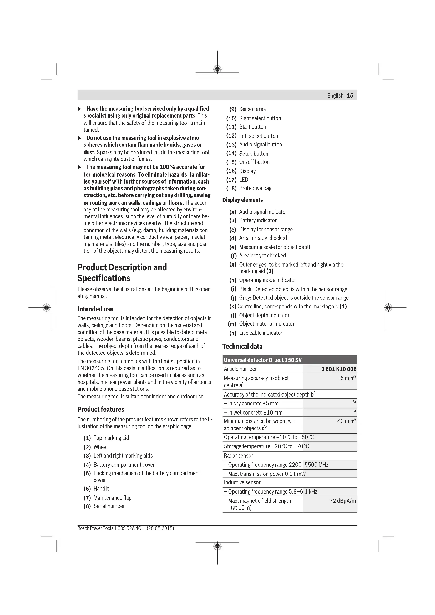
| Measuring accuracy to object centre aA) | ±5 mmB) |
| Accuracy of the indicated object depth bA) | |
| -In dry concrete ±5 mm | B) |
| -In wet concrete ±10 mm | B) |
| Minimum distance between two adjacent objects cA) | 40 mmB) |
| Operating temperature -10 °C to +50 °C | |
| Storage temperature -20 °C to +70 °C | |
| Radar sensor | |
| -Operating frequency range 2200-5500 MHz | |
| -Max. transmission power 0.01 mW | |
| Inductive sensor | |
| -Operating frequency range 5.9-6.1 kHz | |
| -Max. magnetic field strength (at 10 m) | 72 dBμA/m |
16 | English
Universal detector D-tect 150 SV
A) See image
| Max. altitude 2000 m | |
| Max. relative humidity 90 % | |
| Pollution degree according IEC 61010-1 | 2C) |
| Non-rechargeable batteries 4 × 1.5 V LR6 (AA) | |
| Rechargeable batteries 4 × 1.2 V HR6 (AA) | |
| Operating time, approx. | |
| - Non-rechargeable batteries (alkaline manganese) | 5 h |
| - Rechargeable batteries (2500 mAh) | 7 h |
| Weight according to EPTA-Procedure 01:2014 | 0.65 kg |
| Dimensions (length × width × height) | 220 × 97 × 120 mm |
| Protection rating IP 54 (dust and splash-proof) | |
B)Depends on the size and type of the object, as well as the material and state of the base material
C) Only non-conductive deposits occur, whereby occasional temporary conductivity caused by condensation is expected.
The serial number (8) on the type plate is used to clearly identify your measuring tool.
The accuracy and detection depth of the measuring result may be negatively affected if the base material is of poor quality.
For the signal test, which checks whether the measuring tool is receiving a faulty signal, the conductivity criterion and level are used that are defined in ETSI TS 103 361 (V1.1.1) section 9.4.1 for an object depth of d = 60mm .
The following criterion for conductivity is used for the interference resistance test:
Under certain conditions (e.g. electrostatic discharge or application of electromagnetic fields), the measuring results may be lost and it may be necessary to reset the measuring tool by removing and replacing the batteries.
Fitting
Inserting/changing the Batteries
It is recommended that you use alkaline manganese batteries to operate the measuring tool.
Push the locking mechanism (5) in the direction of the arrow to open the battery compartment cover (4) and remove the battery compartment cover. Insert the batteries/re
chargeable batteries. When doing so, ensure that the polarity is correct and corresponds to the diagram in the battery compartment.
The battery indicator (b) in the top status bar of the display (16) indicates the state of charge of the batteries.
Note: Pay attention to the battery symbol as it changes to ensure that you replace the batteries in good time.
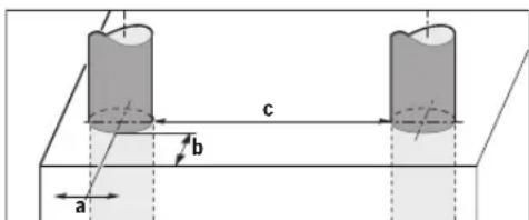
If the warning message
measurements. Replace the batteries.
To remove the battery/batteries, apply pressure to the rear end of a battery as shown in the battery compartment cover diagram (1.). The front end of the battery is freed from the battery compartment (2.), allowing the battery to be easily removed.
Always replace all the batteries at the same time. Only use batteries from the same manufacturer and which have the same capacity.
Take the batteries out of the measuring tool when you are not using it for a prolonged period of time. The batteries can corrode and self-discharge during prolonged storage.
Operation
Protect the measuring tool from moisture and direct sunlight.
Do not expose the measuring tool to any extreme temperatures or variations in temperature. In case of large variations in temperature, leave the measuring tool to adjust to the ambient temperature before switching it on. The accuracy of the measuring tool and the functionality of the display may be compromised if exposed to extreme temperatures or variations in temperature.
Do not attach any stickers or labels to the sensor area (9) on the rear of the measuring tool. Metal labels in particular will affect measuring results.
The use or operation of transmitters such as WLAN, UMTS, radar, transmitter masts or microwaves in the surrounding area may affect the measuring function.
Certain ambient conditions fundamentally impair the measuring results. These include, e.g. the proximity of devices that generate strong electric, magnetic or electromagnetic fields, moisture, metal building materials, foil-laminated insulation materials or conductive wallpaper or tiles. Therefore, also refer to other information sources (e.g. construction plans) before drilling, sawing or routing into walls, ceilings or floors.
How it works (see figure B)

The measuring tool checks the base material of the sensor area (9) in the measurement direction A up to the displayed measuring depth. You can only carry out a measurement while the measuring tool is being moved in travel direction B and with a minimum measuring path of 10cm . Always move the measuring tool in a straight line while applying light pressure to hold it against the wall, so that the
wheels remain in contact with the wall. Objects are detected that differ from the material of the wall. The object depth is indicated on the display, as well as the material of the object, where possible.
Optimum results are achieved when the measuring path is at least 40cm and the measuring tool is moved slowly across the entire area to be checked. The tool's function allows for reliable detection of the nearest edges of objects that run transverse to the direction of movement of the measuring tool.
For this reason, always move crosswise over the area to be checked.
If multiple objects are located over each other in the wall, the display will indicate the object whose surface is nearest to the measuring tool.
The properties of the detected objects as shown on the display (16) may differ from the actual object properties. In particular, very thin objects appear thicker on the display. Larger, cylindrical objects (e.g. plastic pipes or water pipes) may appear narrower on the display than they actually are.
Detectable objects
- Plastic pipes (e.g. water-filled plastic pipes, such as underfloor or wall heating pipes, etc. with a diameter of at least 10mm or empty pipes with a diameter of at least 20mm )
- Electrical cables (regardless of whether live or not)
- Three-phase power cables (e.g. to oven)
Low-voltage cables (e.g. doorbell, telephone) - All types of metal pipe, rod or carrier (e.g. steel, copper, aluminium)
- Reinforcing steel
Wooden beams
Cavities
Possible measurements
-In concrete/reinforced concrete
-In masonry (bricks, porous concrete, expanded concrete, pumice, calcareous sandstone)
-Inlightweightpartitionwalls
Beneath surfaces such as plaster, tiles, wallpaper, parquet, carpet
- Behind wood, plasterboard
Special measuring cases
Unfavourable conditions fundamentally impair the measuring result:
Multi-layered walls
- Empty plastic pipes and wooden beams in cavities and lightweight partition walls
- Objects lying at an angle in the wall
Wet wall material
Metal surfaces
Cavities in a wall; these may be displayed as objects
- Proximity to devices that generate strong magnetic or electromagnetic fields, e.g. mobile phone base stations or generators
Start-up
Switching on/off
Before switching on the measuring tool, ensure that the sensor area (9) is dry. If necessary, use a cloth to dry the measuring tool.
If the measuring tool has been exposed to a significant change in temperature, leave it to adjust to the ambient temperature before switching it on.
Switching on
- To switch on the measuring tool, press the on/off button (15) or the start button (11).
- The LED (17) lights up green and the start screen appears on the display (16) for 4 s.
- If you do not carry out a measurement or press a button on the measuring tool, it switches off automatically after 5 min. You can change this
in the Settings menu (see " ", page 20).
Switching off
- To switch off the measuring tool, press the on/off button (15).
- When the measuring tool is switched off, all settings selected in the menus are retained.
Switching audio signal on/off
The audio signal can be switched on and off using the audio signal button (13). In the Settings menu, select the signal types in the
Measuring process
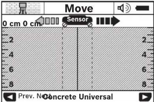
Switch on the measuring tool. The default display screen appears on the display (16).
18|English
Place the measuring tool onto the wall and move it over the wall the direction of travel (see "How it works (see figure B)", page 17) The measuring results are shown on the display (16) after a minimum measuring path of 10cm . To obtain accurate measuring results, move the measuring tool slowly over the entire area you believe to be occupied by an object in the wall.
If you lift the measuring tool away from the wall during the measuring process, or do not use it (movement, press of button) for longer than 2 min, the last measuring result obtained remains on the display. The message <Hold> appears on the display for the sensor range (c). Place the measuring tool against the wall again, move it again or press the start button (11) to begin a new measuring process.
If the LED (17) lights up red, there is an object within the sensor range. If the LED (17) lights up green, there is no object within the sensor range. If the LED (17) flashes red, there is a live object within the sensor range.
Before drilling, sawing or routing into walls, refer to other sources of information to ensure that you eliminate hazards. Since the measuring results can be influenced by ambient conditions or the wall material, there may be a hazard even though the indicator does not indicate an object within the sensor range (the LED (17) lights up green).
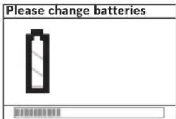
Display elements (see figure A)
If there is an object within the sensor range, it will appear on the display inside the sensor range (c). Depending on the size and depth of the object, the measuring tool may be able to identify its material. The object depth (l) from the nearest edge of the detected object is displayed in the status bar.
Note: Both the object depth indicator (I) and the material property indicator (m) relate to the object shown in black on the sensor screen.
The object material indicator (m) can show the following properties:
Magnetic, e.g. reinforcing steel
Non-magnetic, but metal, e.g. copper pipe
Non-metal, e.g. wood or plastic
Material property unknown
The live cable indicator (n) can show the following properties:

Note: No further property is displayed for live objects.
Unclear whether live or not
Note: Three-phase power cables may not be recognised as live cables.
High relative humidity (>50%) can significantly limit the measuring tool's ability to detect the property "live".
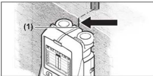
Location of objects
To locate objects, moving the measuring tool once over the measuring path is sufficient.
If you do not find an object, repeat the movement perpendicular to the original measurement direction (see "How it works (see figure B)", page 17).
To identify the exact location of a detected object and to mark the object, move the measuring tool back over the measuring path.
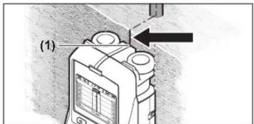
When an object appears in the centre below the centre line (k) on the display (16), as in the example, you can mark it roughly with the top marking aid (1). This marking will only be accurate if the object is straight and positioned exactly vertically, as the sensor area is located slightly below the top marking aid.
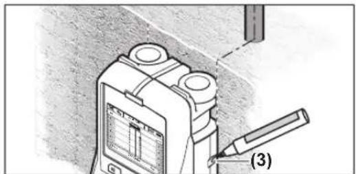
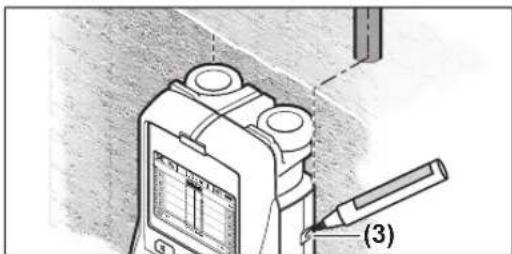
To mark the object accurately on the wall, move the measuring tool to the left or right until the found object is located below an outer edge. When the found object is, for example, shown in the centre of the display (16) below the dashed right-hand line (g), you can mark it accurately using the right marking aid (3).
The course of a detected object in the wall can be determined by covering several measuring paths one after the other (see figure 1) (see "Examples of measuring results",
page 20). Mark and connect each of the measurement points.
Press the start button (11) to delete the display of a detected object at any time and to start a new measurement.
Changing the operating mode
Use the select buttons (10) and (12) to switch between the different operating modes.
- Briefly press the select button (10), to select the next operating mode.
- Briefly press the select button (12), to select the previous operating mode.
By selecting the operating modes, you can adjust the measuring tool to different wall materials. The mode currently set is visible in the (h) area of the display.
(default)
The operating mode
The operating mode
Please note that concrete requires several months to dry out completely.
The operating mode
The operating mode
The operating mode
The operating mode
High relative humidity (>50%) can significantly limit the measuring tool's ability to detect objects.
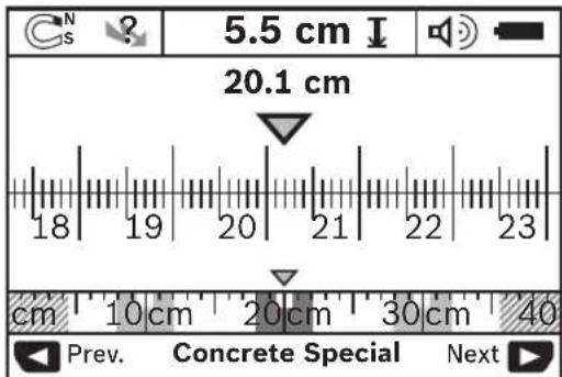
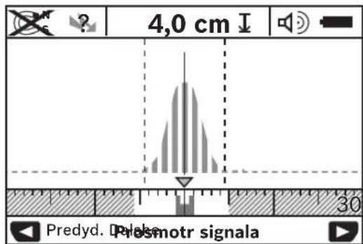
The operating mode
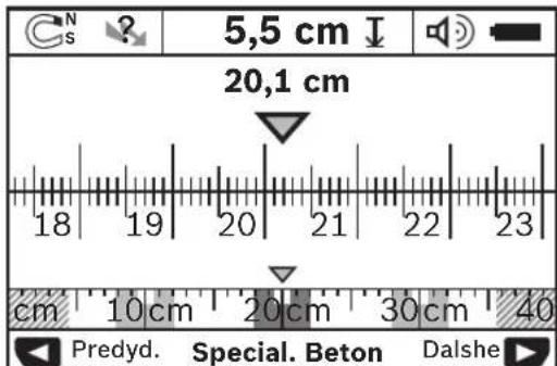
The vertex of the parabolic curve is shown on the small rule above the operating mode indicator (h). The object depth is displayed and, as far as possible, the material properties. The maximum measuring depth is 15cm
The object depth cannot be extrapolated from the signal strength.
Changing the display mode
Note: It is possible to change the display mode in all operat ing modes.
Press and hold the select button (10) or (12) to switch from the default display screen to Metric rule mode.
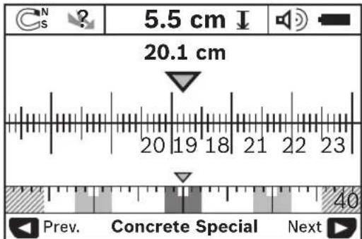
In the example, Metric rule mode shows the same situation as in figure D: Three iron rods, equally spaced. In Metric rule mode, the distance between the centres of detected objects can be determined.
The distance travelled along the measuring path from the starting point is displayed below the object depth indicator (I); in the example, this is 20.1cm
The three detected objects are displayed as rectangles on the small rule above the operating mode indicator (h).
Note: Both the object depth indicator (I) and the material property indicator (m) relate to the object shown in black on the sensor screen.
20 | English
Briefly press the select button (10) or (12) to return to the default display screen.
Note: Only the display is changed, not the measuring mode!
Settings menu
To open the Settings menu, press the setup button (14).
To exit the menu, press the start button (11). The settings that are currently selected are applied. The default display screen for the measuring process is activated.
Navigating in the menu
To scroll down, press the setup button (14).
Press the select buttons (10) and (12) to select the values:
-
Pressing the select button (10) selects the right-hand/ next value.
-
Pressing the select button (12) selects the left-hand/previous value.
In the
In the
In the
<30sec>
In the
In the
The default setting is
- With the
- With the
In the
Advanced settings menu
To open the Advanced settings menu, press the setup button (14) and the on/off button (15) simultaneously while the measuring tool is switched off.
To exit the menu, press the start button (11). The default display screen for the measuring process is activated and the settings are applied.
Navigating in the menu
To scroll down, press the setup button (14).
Press the select buttons (10) and (12) to select the values:
-
Pressing the select button (10) selects the right-hand/ next value.
-
Pressing the select button (12) selects the left-hand/previous value.
The
In the
Examples of measuring results
Note: In the following examples, the audio signal on the measuring tool is switched on.
Depending on the size and depth of the object located within the sensor range, it may not be possible to determine with complete certainty whether the object is live. If this is the case, the symbol 一 appears on the display (n).
Live cable (see figure C)
A live, metal object, e.g. an electrical cable, is located within the sensor range. The object depth is 1.5cm . The measuring tool emits the warning signal for live cables as soon as the sensor detects an electrical cable.
Iron rod (see figure D)
A magnetic object, e.g. an iron rod, is located within the sensor range. Other objects that are outside the sensor range are located to the left and right of the object. The object depth is 5.5cm . The measuring tool emits an audio signal.
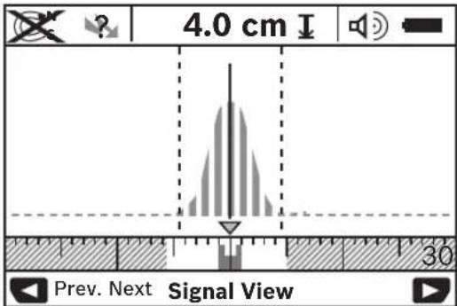
Copper pipe (see figure E)
A metal object, e.g. a copper pipe, is located within the sensor range. The object depth is 4cm . The measuring tool emits an audio signal.
Plastic or wooden object (see figure F)
A non-metal object is located within the sensor range. The object is plastic or wooden and is located close to the surface. The measuring tool emits an audio signal.
Large flat object (see figure G)
A large, flat metal object, e.g. a metal plate, is located within the sensor range. The object depth is 2 cm. The measuring tool emits an audio signal.
Numerous unclear signals (see figures H-I)
If numerous objects are shown on the default display screen, the wall probably contains a large number of cavities. Switch the operating mode to
ities. If the measuring tool continues to display too many objects, take multiple vertically offset measurements and mark the displayed objects on the wall. Offset markings are an indication of cavities, whereas markings in a straight line indicate an object.
Errors - causes and corrective measures
| Error Cause Remedy | ||
| Measuring tool cannot be switched on. | Batteries drained Change the batteries | |
| Batteries are inserted with incorrect polarity | Make sure batteries are inserted correctly | |
| Measuring tool is switched on but not responding. | Remove and reinsert batteries | |
| Measuring tool too warm or too cold | Wait until it reaches the permitted temperature range | |
| Display: <Slipping Wheel> | Wheel losing contact with wall. | Press start button (11) and move measuring tool, ensuring lower two wheels stay in contact with wall; on uneven surfaces, place thin piece of paper between wheels and wall |
| Display: <Speeding> | Measuring tool moving too fast | Press start button (11) and move measuring tool slowly over wall |
| <Temperature over range> | Wait until it reaches the permitted temperature range | |
| <Temperature under range> | Wait until it reaches the permitted temperature range | |
| <Strong radio signal detected> | Measuring tool switches off automatically. If possible, remove the interfering radio waves, e.g. WLAN, UMTS, radar, transmitter masts or microwaves, then switch the measuring tool on again. | |
Maintenance and Servicing
Maintenance and cleaning
Check the measuring tool before each use. If the measuring tool is visibly damaged or parts have become loose inside the measuring tool, safe function can no longer be ensured.
Always keep the measuring tool clean and dry to ensure optimum, safe operation.
Never immerse the measuring tool in water or other liquids. Wipe off any dirt using a dry, soft cloth. Do not use any detergents or solvents.

Ensure that the maintenance flap (7) remains securely closed at all times. The maintenance flap must only be opened by an after-sales service centre authorised to work with Bosch power tools.
Only store and transport the measuring tool in the protective bag provided.
If the measuring tool needs to be repaired, send it off in the protective bag.
After-sales service and advice on using products
Our after-sales service responds to your questions concerning maintenance and repair of your product as well as spare parts. You can find explosion drawings and information on spare parts at: www.bosch-pt.com
The Bosch product use advice team will be happy to help you with any questions about our products and their accessories.
In all correspondence and spare parts orders, please always include the 10-digit article number given on the nameplate of the product.
Great Britain
Robert Bosch Ltd. (B.S.C.)
P.O.Box 98
22 | Français
Broadwater Park
North Orbital Road
Denham Uxbridge
UB95HJ
At www.bosch-pt.co.uk you can order spare parts or arrange the collection of a product in need of servicing or repair.
Tel. Service: (0344) 7360109
E-Mail: boschservicecentre@bosch.com
Ireland
Origo Ltd.
Unit 23 Magna Drive
Magna Business Park
City West
Dublin 24
Tel. Service: (01) 4666700
Fax: (01) 4666888
Australia, New Zealand and Pacific Islands
Robert Bosch Australia Pty. Ltd.
Power Tools
Locked Bag 66
Clayton South VIC 3169
Customer Contact Center
Inside Australia:
Phone: (01300) 307044
Fax: (01300) 307045
Inside New Zealand:
Phone: (0800) 543353
Fax: (0800) 428570
Outside AU and NZ:
Phone:+61395415555
www.bosch-pt.com.au
www.bosch-pt.co.nz
Republic of South Africa
Customer service
Hotline: (011) 6519600
Gauteng - BSC Service Centre
35 Roper Street, New Centre
Johannesburg
Tel.: (011) 4939375
Fax: (011) 4930126
E-mail: bsctools@icon.co.za
KZN - BSC Service Centre
Unit E, Almar Centre
143 Crompton Street
Pinetown
Tel.: (031) 7012120
Fax: (031) 7012446
E-mail: bsc.dur@za.bosch.com
Western Cape - BSC Service Centre
Democracy Way, Prosperity Park
Milnerton
Tel.: (021) 5512577
Fax: (021) 5513223
E-mail: bsc@zsd.co.za
Bosch Headquarters
Midrand, Gauteng
Tel.: (011) 6519600
Fax: (011) 6519880
E-mail: rbsa-hq.pts@za.bosch.com
Disposal
Measuring tools, battery packs/batteries, accessories and packaging should be sorted for environmentally friendly recycling.

Do not dispose of the measuring tools or rechargeable/non-rechargeable batteries with household waste.
Only for EU countries:
According to the Directive 2012/19/EU, measuring tools that are no longer usable, and according to the Directive 2006/66/EC, defective or used battery packs/batteries, must be collected separately and disposed of in an environmentally correct manner.
Français
Robert Bosch (France) S.A.S.
Calle Robert Bosch No. 405
C.P. 50071 Zona Industrial, Toluca - Estado de Mexico
Tel.: (52) 55 528430-62
Tel.: 8006271286
Taend/sluk signaltone
Med knappen Signaltone (13) kan du aktivere/deaktivere lydsignalet. I menuen Indstillinger kan du i untermenuen
Maleprocedure
Taend for malevarktojet. Pà displayet (16) vises standardskarmbilledet.
66 | Dansk
Bosch Service Center
Telegrafvej 3
2750 Ballerup
Pá www.bosch-pt.dk kan der online bestilles reservedele el-ler oprettes en reparations ordre.
Tlf. Service Center: 44898855
Fax:44898755
E-Mail: vaerktoej@dk.bosch.com
70 | Svensk
Bortskaffelse
Bosch Service Center
Telegrafvej 3
2750 Ballerup
Danmark
Tel.: (08) 7501820 (inom Sverige)
Fax: (011) 187691
Avfallshantering
Evpeyoroion/anevepyoroion
PvTvEvpyooinTou opyavou mptponc Bbaowte, ot npoxn Tou aonmpa (9)evivu uy. Evexoyovocouniote e eva oeyvo nvl to opyavo mptponc.
Eeepintwnnou to opyavo metponnc ntrav eKTEemuvo oiaxupc diakumavoeic cepokpaia tote, npv to teae o aeiouvia, apnoTe va anokriocraoepn cepokpdaia.
OeogcAetroupyia
TnveevpyoioiOn Tou opyavou metponc nntote To nKtpo On-Off (15) nTo nKtpo ekkivonc (11).
-HpwoTobiooc(LED)(17)avapei npaoivn kai oyn apxkn oovn epaaviotai yia 4s (16).
- Σe neplwnou nou yia 5 min (λemá) δev nαπθeikaveva nληκτρο, tóte to opyavo μετροιnc anévepyonoietai autóμata. Στο μενον Puθμiαic μnopeite va aλλεεte autov Tov xpov0
Anevpyooinon
- Tn anepeponoin tou opyavou metpno nntote to nKto On-Off (15).
- O'Tav to opyavo metpnon anevepyonoiEi, oTo meou diatnpovvraloec oI emayevecpuOuioic.
EvpeynoinAnEvepyoonn tou nxtukoi oumuoc
Me to nKto Hxntko oHa (13) npoetre va evpyonouaote hva anevpyonouaote To xnTko oHa. TTo evou Puioic kai oTo unopevou
Aiaubkaiaaieptponc
Evpyonoiote to opyavo metpnoc. TnV oovn (16) epaaviotan otavap oovn evoeiEevv.
TOnoTeHnote to dpyavo pEtponc naw oToV toxo kai knote to onv kateuovn obynonc (Bene «TpOnc aeoupyiac (Bene eikova B), Zelida 93) naW oToV toxo. Ta anotaleaupata nC pEtonc mTa ano ia elaxiOnn anootaan pEtonc 10 cm epavicovra atny oOvN (16). Tia va enituxete apota anotaleaupata npenei va kiveite to opyavo pEtonc apya evteAoc naW ano to avtikepevo, nou unoTeTe, ot Bioketai oToV toxo.
'Otav kata tn diapkeia tnc metponc aavaankwaete to opyavo metpnanc an tov toxio n otav dev to xeiipoteire nepiaooTepo and 2 letna (klvn, nattma nAnktpou),toTe toteutalo anotaleaua nnc metponc napapeve oyn oovn. Tnv evdeiEn nnc nepioxnc tou aoqntnpca (e) eupavicetai to npvupaHold> (Suykpatpan).OTav tonoethnoete to opyavo metponc dava naVw oTov toxio, auvexioe va to petaivelte n nathe cTo nAnkpto ekkvnaoc (11),Eekivd n metpnao nto tv apxh.
AahaynTwvTponwAetroupyiac
Me ta nAkpTa enAooyic (10) kai (12) mOpoei te va aAldete petaDiaopopetikw TpOiw Aeioupyiac (Modi).
-πaHote auVToa to nAHToPo eUOyNc (10), va va enIaeTe roe oevToPOno aeToupyiac.
-πaHote ouvtoua to nAHTPO eiuoynic (12), ia va enIeTe ro nponyouevo tropo aeioupyiac.
Me tyn emoyi twpionw aeitoupyiac nopetre va npoapuoeTe to opyavo metponc oia diaipopetika uka
96|EALnVik
Toxou. H EKOATOte p0HmI mOpel va aaywpiotel onoteohnote otny nepioxEvdeEewy (h) nC oOvnc
AALLayntpnonouevdeIeNc
YnobexMia aalaynTwvTpOnw evdeEnc eivat duvat noe olouc touc pronouc aeitoupyiac.
Pnntne napateraev to nAHTPO enuoync (10) (12), va aAaeTe ano tn oavap oovn evoeiEew otn aeitoupyia klaikac.
H letoupyka kaiakac dcexyve oto napadeiyma tvn lida kataaanaon onwocntny eikova D: Tpeic oipnepc paiboi otny lida anoataan. Me tn letoupyka kaipakac mnpetre va Eaekpiobote nvo anoataon avaeoea ota kevtpa tuxov avxveuevuvavtikeevuv.
Katw ano Tny evdeiyn ia daoc avtkejevou (I) avaepepaia n diavuieia anotaan metponanc an to oneio ekivnonc, oto napedeya 20.1 cm.
Tn mki np klaipaka naw ano Tny ev6e1n tou pnonou
Aetoupylac (h) epaivocvat Ta avxvemuva Tpia avtkiepeva
WC opoywvia.
YnodEgN: Too ng evbEeTou eItnpenoevou bOouc avtkemuevou (l) 0o enioc kai n idiotna tou uAikou (m) avapepovta tO paupo epaviQevo avtikemuovo tOv aio0ntpa.
Tia va eniTppeyete otntavtap oBovn evbEiEev, nntote ouvto Ta nAikpto eIaoync (10) (12).
YnOeEg: Mov ngvEoEg n aAaCe, oXn aeoupyia pTnponC!
MevoPouoioe
Tia va nepdoete oTo pevou PuOmuic, anpOCTe to nAHTPO Setup (14).
Tia va eykataleipete to mevo, narnote to nAkrpo ekkivnang (11). OI pexouoe enieyvee oepuioeic epapuoovra. Tia ngdiadikaaia metponc evpyonoeirat noavrapoovn evdeieewv.
Tlhoynono o evo
Tnntote to nktpo Setup (14), ia va tegakivtheire npoc ta kATW.
Tnntote ra nktpa emooyic (10) kai (12), yia va eneEeTe TIC TmuEc:
-Me to nAikpto eiuoyn (10) enieTe Tn deia n Tny enouev n tni.
-MeTnAikpo eunoync(12) eunaeTe nV apoteepn Tny nponyouevnTuH.
(Fawoo)
T0evo
(Xpovoc anvepeyoinoŋnc)
T0eov Cut-off timeXpovoc anevepyooinc)
mopetve va putheta epe opiaeva xpvika diaotmuata,eta ta
onola to opyavo metponc npenei va anevepyoointhetai
autouata,otav nepaatonoinkai kajla diaokaia
metponc n kajia puthetaan. Exovnpopoit<5 min>
(5Aemra).
(Δαρκεια φωτισμου)
Robert Bosch Sp. z o.o.
Bosch Service Center PT
K Vapence 1621/16
692 01 Mikulov
Na www.bosch-pt.cz si si muzete objednat opravu Vaseho stroje nebo nahradni dily online.
Data n3roTOBneHn yka3aHa Ha noCleJeHc CTpaHnue 0bIokKnykoBOcTBa HnHa KOpNcy H3dEHH.
KoHTaKTHa HnΦopMaun OTHocTeNbHO HmnpTepa coepKHTcHa ynaKOBKe.
Cpok cnky6bln3dennr
Cpok cnky6b H3dennn coctabnet 7 net. He pekomehnyet cKcnnyataun no ncteehnn 5 net xpaehnca dbl n3roTOBNEHn 6e npedapntenbHO npOBepKN (daty n3roTOBNEHn CM. Ha 3TNKeTke).
Ipeueenb KpHTHuecknx OTka3OB H OoHbOuHbIe DeiCTBnepcoHaHa HIN NOnb3OBaTeN
-HeNCIb3OBaTbPnIOBLeHINDbIMaHENOCpeCTBeHHO H3 KOpNyCa H3dEHH
-HeHCIOB30BaTbHaOTKpbITOMPPOCTpaHCTBEBOBpeMdoJRA(BpaCnblAeMoBBoe)
-He BKNIOUaTb pni NOnaHaHH BOBbl B KOpNyc
KpntepnnpeenbhbixcoctoHH
- noBpeKdEe KOpNc H3deJIINr
TnH N nepHOuHOCbTexHHueCKOrO 6cnyXBaHHN
PekomeHyetycOuHCTnTb HNCTpyMeHT OT bIIN NocIe KaK-DOHOHCNOB30BaHH.
Xpahenne
-Heo6xOJMO XpaHnTB B cyXOM MeCTe
-Heo6xoJMO XpaHntb BdaIIN OT HCTOCHKOIB NOBblieHbIX TemnepaTpy IN BO3dEInCTBnCOnHEhBix nyuei
- npxpaHHeHH Heo6xoHMo H36eRaTb pe3KOrO nepenada TemnepaTp
-eCNHnCTpyMeHT NOCTaBnIeTCB MMRKO CymKE HIN PnACTKOBOM KeCe peKOMeHnyETC XpaHHTb INHCTpyMeHT B3TOI 3aUHTHOYNAKOBKe
- noDpO6HbIe Tpe6oBaHnK yCNOBnM XpaHeHHcMOTpnte BFOCT 15150 (YcNoBne 1)
TpaHcnpTnpoBka
KaTeROpUeCKn He DOnyckAeTc NaJeHHe N IIObIe MExaHueCKe BO3dEInCTBn Ha yNaKOBky pN TpaHCnOpTIpOBe
-npi pa3py3ke/norpy3ke He onyckaeTcHcnoIb30BaHne IIO6oR Bua TeXnKn,pa6OtaOeJ no pInHunny 3aKMa yNakOBKn
-ⅠΟДРБИБLE Tpe6OBaHINK YCNOBbAM TpaHcNtPnPOBKN CMOTpHTe B FOCT 15150 (YcNoBne 5)
Yka3aHnno TeXnke 6e3oNaCHOCTN

IpoHTaTe N BbINONHnTe BCE yKa3aHHN. McNoB3OBAHHe N3MePHTeBHO HcTpyMeHTa He B COOTBeTCTBMn C HAcTOAHHM YKa3aHHMaH NpeBaTo NOBPEXKeHHem HHTe
rnpoBaHHbix 3aunTHbIX MExaHn3MOB. IOKANYIcTA, HADEXKHO XPAHNTE 3TN YKA3AHNR.
PemOHnH3MePHTeBHOHcHtpyMeHTa pa3peeaetc BbINONHrTb TOnBKO KBANHΦNpOBAHHOMY Nepcoany HToBko CHCNOB3OBAHmOpHnHaJIbHbIX 3AnuCTeN.3TNM OecneuBaETcB630NaCHOCTb H3MePHTeBHO HOHcHtpyMeHTa.
He pa6otaTe Cn3MePHTeNbHbIM HNCTpyMeHToM Bo B3pbIBOONaCHOcpe, No6nH3OcTH OT rOpHux KIOKCTe, ra3OB Nblnn. B n3MePHTeNbHOM HNCTpyMeHTo MOryT Obpa3oBaTbCn HCKpbl, OT KOtOpbIX MOKeT BOCIIa-MEHHTbCnblnlnPaBbl
TExHONruecknmpuHnHaM3MepeTebHbH HNCTpyMeHT He MoKET rapaHTpOBAt bCTOnpoeHTHyIOcTOBepHOCTb.Bo 36EkaHne OaChOCTn nepe CBepeHHem,paCNHbAHem HnΦpe3epoBaHHem B CTehax,NOTOKkA H NONY o6e30anctbe c6a HnFOpMaueH N3DOnONHTeBbHX NCTOuyHKOB,TAKHX,KAK CTPOENTbHbIE CHPTeK, HrTOBNeHHe BO BPEMa CTPOENTbCTBa FOToRpaHn H.T.P.AkTopbl OKpyKaU OIe CpeB, HApP.,BnaXHoCTb BO3dYa, HnPaCNoLoKeHHbI NOJIb3OcTH DpyHe 3NEKTPueCKne np6Opbl MOryT OTPuCaTeBbHO BnHbTa Ha TOOHCTb H3MepeTebHo IHOHTpyMeNTa. KOHCTpyKua IN COToTHne CTEN (HapP., BNaXHOCTb, CTPOENTbHbIe MaTePhaJIbIc CODepXaHHem MetaIIa, 6oHN CTOKONPOBOJIMN CBOINCTBaMn, H3OJIa
HONHbIe MaTePnAbl, PNTKa), a TaKxke KOJIyueCTBO, BND, pa3Mep H NOnOKeHHe OBeKToB MOrY T NCKaKaTb pe- 3yNbTaBtN3MepeHH.
Onncahne npoodykTa n ycnyr
Ptoxanycta,co6nlaTe nlloctpaunB hauane pykoBOCDBa no kcnnyataun.
PpHMeHeHne No Ha3HaueHHIO
N3MepntbHn HnCTpymEn TnpaHa3NaueH nIy noncka
obkeTOB B CTeHax, NOTONKx NnONax. B 3aBNCMOCTN OT
MaTePHNA N COCTOHN NOBepXHOCTe Cero NOMOJIbIO
MOxHO HAXoNTb MeTaNlHuECKHe obkeTb, DepeBHHbIe
BaIKN, PnAcTMaccOBBe TpybI N Ka6enN. InybHa 3aneraHn
HaJdEHNO obekTa OnpeDJIeTcN o BEpXHemy KpaIO
obkeTa.
H3MePHTbHbHn HnCTpymEn COOTBcTBye TnpedHbHBM 3HaueHHa BCOoTBcTbHN c EN 302435.Ha 3OM OCHOBaHHnpeepnPHMeHHenEM B6OblHuaX,A3CN B6ln3n a3poNpOToB, a TaKKe cTAHcN Mo6bHbHO CBA3n CnEyET BbHCHTb, DOnyCTMn Nn HCNoJIb3OBAHne DaHNO HnCTpyMeTa. H3MePHTbHbHn HnCTpymEn pPiroDe nIpaBoTb BHyTpNIOMeUeHHn Ha OKpbITOM BO3dyXe.
1306paxeHHbIe coCTaBHbIe qACTH
HymepaunippectabnEHbIXcoCTaBbIXuacteBbINOnHeHa no 1306paKeHHIO h3MepeHTbHO HOHCTpyMeHTa Ha cTpaHnCe C HNIOCTpaUNM.
(1)BepxHnIpa3IpaMapKpObKn
(2) PoJHK
(3) Nebbl/npabblnazdlnMapknpoBKN
(4)KpbIka6batapeHoroOtceka
(5)Фнкатop крblшкбатapeиHorToO orTecka
(6)PyKoRTHa
(7)OTKnHaJ KpbIkaDnTexHueckoroO6cnyKaBaHHa
(8) CepinHbI HOMep
(9) CencopHan 30Ha
(10) Khonka Bbibopa npaba
(11) Khonka «ctapT»
(12) Khonka BbIbopa neBa
(13) Khonka 3BykoBoro ciHana
(14) Khonka Hacptpoikn
(15)BbiknloaTeIb
(16)Диспел.
(17) CBeToDnOa
(18)3aunthbnyyexon
3nEMeHTbI HnHnKaun
(a) INHINKAtop 3BYKOBOrO CnHnHa
(b)Индикатор заразда 6атAPEn
(c) INHINKAtop ceHCOPHO30HBi
(d) Yke HCCJIeIOBaHbIyUaCTOK
(e) ⅢkaIaIIN3MepeHHrIy6HbI o6beKTA
(f) Eue He HncIeNoBaHnHy yUaCTOK
(g) BheuHne Kpa,OTmeauoTcNo neBOMy/npaBOMy na3y (3)
(h) INdikatoppekHMa pa6oTbI
(i) UepHbI: 6bHaayKeHHbI 6bEket B CeHCOPHO3OHe
(i) CepbI: 6hApyKeHHbI O6BeKT BHe ceHCOPHOH30- Hbl
(k) CpeHnHnHH, COOTBETCTByeT na3y nIa MapKnpoB
(1) INHnKaTopIy6HbI3aIerAHnI O6bEka
(m) INHdkatop MaTePnHa o6BeKaT
(n) INHdikaTop TokoBeyuieepnpoBodkn
TexHHueckne daHHbe
OHaHnHnHnHnHnHnHnHnHnHnHnHnHnHnHnHnHnHnHnHnHnHnHnHnHnHnHnHnHnHnHnHnHnHnHnHnHnHnHnHnHnHnHnHnHnHnHnHnHnHnH
PnHe6NaornpHrTHbIX CBOCTBax OCHOBAHHpe3yNbTaI 3MpeHnMoKet OKa3aTbC TcOKN 3peHHTOoHOCTN rny6HbH HCCNEOBAHHxYKe.
ДлгИнсblытаньпремннka,В рамкax кOTopoRo npOBepETcBBO3dIeCTBnE CHrHaI NOMEXHа H3MepTeIbHbINHCTpymENT,ИСПОЛБ3уETcKРТЕРиИуPoBeHbpa6OToCNoCo6HocT,ONpeJIeHbBTEXHueckoCneuФКaцYNETSI TS 103 361 (V1.1.1) pa3d9 9.4.1dЯ rny6Hb3anerahnna obBeKaTa d=60 MM.
B OTHOWeHH NOMExOyCTOnuHBOCTn pPmHeHETc CNeDyO- ⅢKpIeRn pa60ocncobHcTn:
Pn onpeeneHHbIX ycnoBHX (Happ., 3eKtpocTaTHueckn pa3paed nn B03deTcBne 3eKeTpoMaHTNHbIX nOen) Ha pe3yIbTaBt b3MepeHn MoKet OKa3bIBatbC8 B03dECTBNE, TEKUyIepe3yIbTaBt b3MepeHn MOYr 6bTb YTpaeHbI MoKet Notpe6oBaTbC9pe3aRpy3Ka N3MepNTelbHorO HNCTpyMeHTa Nytem h3BleueHn 6bataeek H yCTaHOBKn IX Ha Me-CTO.
C6opka
BCTaBa/3aMeHa 6aTaapeek
B H3mepnteHbHom IHcTpyMeHTe peKoMeHnyETcHcNoIb30BaTb ⅡeNoUHO-MapraHcEBBie 6aTapeKN Nn aKKyMylrTopHbIe 6aTapeN.
YTo6bIOTKpbTb KpbWky 6batapeHoro OTeCka (4), npHKMnte fHKCaTOp (5) B HnPaPbNeHH CTePKN CHMHTE KpbWky 6batapeHoro OTeCka. BCTaBtE 6batapeHKn Nn AkkymnTophie 6batape. CneHTe npn 30m 3a npaBnHOB NOJAPHOCTbBO CORNACHO N3O6paXeHH BO TcKe 6batape.
Hndkatop 3apra6baTapei (b) B bepxne cTPOKe DnCnnen (16) oTo6paXaet CTepeh 3apra6baTapei/AKKymytnaTOPOB.
Yka3aHHe: CnDHTe 3a n3MeHEnHm CnMBONa 6aTapei, UTO6bI BOBpEm 3aMeHtB 6aTapeN/akkMyJrAToPbI.
Pozh.,pomenyayte batareyu

国
PnnoBnHnHa nncnnee (16) npdynpexk<PoHz.,pomenyate
batareyu> HacpoiKn coXpaHAROTc IN 3MepHTenbHbINHCTpymeHT ABtOMaTHueCKNOTKlnOuaTcR. IpOdoJKeHne
H3MepeHH 60nee HeBO3MOxHO.3aMeHInTe 6atapeKn HnAkkymyIATOpHbIe 6atapen.
UTo6bI H3BNeYb 6aTapeN/aKKyMylrTopbI, HaKMMte Ha 3aHn KOneuc 6aTapeN/aKKyMylrTopa, Ka NOKa3aHo Ha pCynKe C 3IO6paxKeHHem 6aTapeHOrO OTceKa (1.). IpePeHn KOneuc 6aTapeN/aKKyMylrTopa BbIXoHIT N3 6aTapeHOrO OTceKa (2.), TaK UTo 6aTapeU OIN aKKyMylrTop MoXHO C neKOCtBu H3BNeYb.
Bcerda 3aemeHnTe Bce 6atapeKn/AKKymyIaTOpHbIe 6atape OndHOBpeMeHHo. IcnoIb3yIte TolkbKO 6atapeKn/AKKymyIaTOpHbIe 6atapeOn OndHOro pOHN3BOIHTeN c OOnHaKOBOI emKocTbIO.
H3BnkeaTe 6bapen HnN aKkyMnyTOpbI H3 N3Mepe TELbHO HOHCTpyMeHTA,ecnn npOOnNXTeNbHO Bpe MHe 6ydeTe pa6oTaTc Hm. PnDnITeNbHOM XpaHEn HNO3MOXHa Kopp03H Nn CamopaaPdka 6bataeek/ aKkyMnyTOpHbIX 6bapaei.
Pa60Ta c HhctpyMeHTom
3aunuatae H3MepeTebHbHn HnCTpyMeHT O BnAHN PnPmblcxOnHeuBix Nyuei.
He noDBepraIte H3MepHTeBbHINHCTpymENT BO3-DeiCTBHO 3KCTpeMaIbHbIX TempeaTpH IN TEMpeaTpybIX nepenAOB. PnH 3NaHTeBbIX KOneBaHHX TempeaTpby DaTe HNCTpymEny PepeB KBNIOeHNH E Chauana Cta6HIN3HPOBat TEmpeaTy. 3KCTpeMaIbHbIe TEMpeaTpby H INTEMpeaTpHy IpepeaDbl MOrTy OTPiuTaTEbHO BInrA Tb HA ToUHOCTb H3MepHTeBbHO INHCTpymEHTa INHINKaUHO Ha DnCnIee.
He npHKpenIe BceHcOpHo 3Ohe (9) Ha o6paTHO CTOPHO H3MEpHTeBHoro HnCTpyMeHTa HAKNeKn HnTa6nueKn. BOC6eHHocn MeTALnueckne Ta6nueKn MoRyT OKa3bBaTb BNnHHe Ha pe3yJbTat H3MepeHN.
Pa6ota nepepaiox yctpoiCTB, TaKx KaK WLAN, UMTS, abnapadapOB, paHOMaHT HMKPOBOHOBbIX neeH, MOKeT NOBnATb Ha N3MePHTeBHyIO fYHKuHn HHCTpyMeHTa, ECIN OHN PaCpONOKeHbI B HeNoCpeDCTBeHHo 6hN30cTH.
B cnny npnunna pa60tby n3mepehtenbHoro nHcTpyMeHTa HeKOTOpbIe ycIOBn OKpyKaUoJe Cpebl MoRyt BnNtB Ha pe3yNbTaB I3mepeHH. CioDa OTHOCHTc, HApP, 6n3OCTb np6bOpB, 3n7yauOuXs CNbHbIe 3NeKTPhueckne, MaHTHbIe HIN 3NeKTpOMarHHTbIe NnI, BNara, CTponTeMbIe MaTePhaNbIc COepJxAHem MeTaN, H3OnuONHbIe MaTePhaNbI, KaHNPOBaHHbe AInOMHHem, TOKOpBOJaune o6o HnnNTka. Ito TnpUnHe pPmnte BO BnHMaHne nepeCBepeHHem, pacININBaHHem HnI fpe3epOBaHHem B
CTehax,NOTOKkxHnNnOly TaKke NdpyrHe HcToUHKnHHΦopMaun(HaNP.,CTpOnTeNbHbIe YepTeKn)
PpHnHn nn deiCTBna (cm. pnc.B)
C NOMOUIbIO H3MEpHTeBHO
TO HCTpyMeHt NaPObepReT
C OCHOBaHHe IOD CeHCOP
HO 30HOJ (9) B HApPaBHe
HIN A DO OTo6paKaemr Iy
BnHbI H3MEpeHn. H3MEpe
Hne BO3MOKHO ToIbKO pN
DBHXeHN H3MEpHTeBHO
HCTpyMeHt BA HApPaBHe
HIN B, MHHMaJIbHa JINHa
yAcTka CoCTaBnE10 cm.
BOJIne H3MEpHTeBbHM
HcTpyMeHToM BcerDa npA
MOHHeHbIO No CTHe, Cner
Ka HaxmHa Ha Hero, YTO6bI
KonechknXopo0o conpHKacannbc co tcnH. Paon03HaOTc8ObekTb, OTnHauOunecr OMTapehnaCTenbl. HaDncnnee oTObpaKaetc rny6nHa 3anerHn8ObekTa nNo BO3MOxHOCTMapehnaOBekTa.
OnnmaHbIe pe3yIbTaTbIoCTraIOTcKorDaIINHa yuaCTka H3MepeHHa COCTaBnIeMHN.40 CM H3MePHTeB hHy INCHTpymEt MeIeHNO IepMeUaETcN IO Bcemy O6 cJeMyOMy yuaCTky.Bcny fynKuHOHaNbHixOCoBeHooCTeH HAnBoJe HaeJxHO 6hApXHBaIOCTeBepxHKe pAObEkoB,paIIOJOKeHHbIe NonepeuHO K HapBaJIeHHIO dBIXeHHa H3MePHTeBHO INCHTpymEtA.
ItoTOnPiuHHepeKoMeHdyetcHccneDobatb yactok, nepemueaH3MePHTeNbHbHnHCTpyMeNTBpa3hbIX HanpabNeHHx (kpect-hakpect).
EcnBCTeHaeHXoDNTcHecKoNbKOObbKeTOBdpyHaIpyROM,HaIcnPeeOTobpaKaETcObBeKT,HaxoDnHiC86nJKeBCeroKnOBepxHOCTN.
OTo6paKaembIe Ha nHcNpee (16) CBOiCTBa HauDeHHbIX oBekTOB MOYr OTINuATbCRAOT INx paKTHueCKNX CBOiCTB. B OOCoEHocHTn 3TO KacaetcO uChb TOHKX oBekTOB, TOniHa KOTOpbIX HA dncnnee 60JIbWe, YEM B DeIECTBtNEbHOCTH. KpyNHbIe cinnHPrueckne oBekTbI (HapP..PiactMacCOBble NIN BOIOpOBoHNbIe Tpy6bl) MOYr BblrJdTeH h DaNC- nIIee TohSe, YEM B DeICTBtNEbHOCTH.
06hapyxNbaemble 06bekTbl
-ⅡnactMaccOBbie Tpy6bl(Happ..3aONHeHHbB BOOII nIacTmaccOBbie Tpy6bl,TaKne KaK Tpy6bl OTOnJIeHN B NOIy,CTeHax H.T.D.C MHN. DnAmETpOM 10 MM, Nyctble Tpy6bl C MHN. DnAmETpOM 20 MM)
-3NeKtpoPBOJka(He3aBcHMoOTHaIHHNIOITCTBNAHapXeHHN)
- npoBODka Tpexpa3HOro nepemehHoro ToKa (HaNP., npoBODka KxOHHO nnHtBi)
-HN3KOB0BbTHaH npOBoKa (HaNP..npOBoKa DBePHO 3BOHka, Tenefoha)
-MetanHueckne Tpy6bl,CTepKHH,baKNBCEX BNDOB (HaNP.,n3 CTaHH,MeHH,aIOMHHH)
- apmAtypa
-DepeBHHbIe 6aIKn
-nycTOTbl
N3MepeHHB03MOXHbI
-B6eTOHe/JKeEnE3oBeToHE
-BCTeHOBo KnaKe (KnpnH, npOpCTbH n NeHo6eToH, NEM3OBbI KAmEh, CNINKaTHbI KNPnH)
-BCTeHAXIeKHXCtPOINbHBIX KOHCTpyKuN
-IOJ TAKHMN IOBepxHOCTMy KAK UTyKaTpyKa,KepaMnueCKaI NHTka,O60,NapKET,KOBpOBeI NOKpbITnA
-3aДревснов,ГИСКОТОН
Ocobie cnyan
B cnny npnHunpa paoTb H3mepntbHoro HNCTpyMeNTa Ha pe3yNbTaH3MpeHHN MOrTy OTPnuatEnbHO B03dEChTBoBaTb TAKHe He6IarOpnRTHbIe yCIOBnA: -MHOROCNoHnKaOHCTpyKUaCTeH
-nytble nnaactmaccobble tpybblnpebeHHbte 6aKINB PNOCTRX hCTeHAX JERKHX KOHCTpyKUH
-06bekTbI,3aJIeraIOUe BCTeHax NO DaHOHaHH
-BAJXHbIMaTePnaJICTeHbI
-MetannHueckne NOBepxHOCTN
-ПОJOCTNВСТЕ;ОнMМOTOTOBpaKaTbCakOБьektb
-5NIOCTb K pnp6opam C cnHbHbIM MaHHTbIMn HnI 3NeKTPOMaHHTbIMn NOIaMn, Hap., 6a3aMa paIIOTepeHOHBn IehePApam
BkIIOUeHHe 3NeKToPOnHCTpyMeHTa
BkIIOueHne/ByIKIOueHne
Peped BkIOeHHem H3MePHTeBHO HOHCTpyMeHTa 063aTeBHO y6eINTecbBTOM,TOceHCOPHA 30 Ha (9) cyxA. PnH Heo6XoHNMOCTn PpOTpHTe H3MePHTeBbHIn HcTpyMHT HaCyXo.
Pocne pe3Koro H3MeHHe TEmpeaTpybl H3MepHTeBbHb HnCTpyMeHT CnEyET BbIepKaTb NpeD BKIOUeHHem Do BBipAHHBaHna TEmpeaTpybl.
BknIOueHne
-UTo6bIKNIOHTbI3MEpHTeBbIHHCTpyMeH,HAKMnTe BbIKIOATeB(15)ININ KHOKNKY(CTapT)(11).
-CBToIOHOI(17)3aIopaeTc3eENbIM,HHa4cHaIIN- nnee(16)noBnRETCHauAIBHOeH3OpaXeHne3KpHa.
-ECnBbHe npOBoHte H3MepeHHaMeHTbHbIM HnCTpyMeHTOM He HaKHaMaTe Hn Ha KaKHe KHOKN,Yepe3 5 MIn. H3MeHTeHbHbI NnCTpyMeHT aBTOMaTHueCKn BbIKIOaETc.B MeHIO HAcTpoKn Bbl MoKeTe H3MeHNTb 3TO BpEMr
BbIKIOueHne
-UTo6bBbIKHOHTbH3MePHTeNbHbINHCTpyMeHT,HaKMTe BbIKIOaTeNb(15).
-Пи ВькИоуeHHи H3МерпгельHOrO ИСHTpyMeHTa BCEпОнЗБeDEeHHbE B MeHIO HAcTpoHKn COxpaHЯTOcR.
BkJIOUHHe/BbIKIOUHHe 3ByKOBOrO cnHaHa
C NOMOUIKHOHNIK3BYKOBOORCNHana(13)BKNIOUaETCRN BYIKIOUAETCR 3BYKOBOI CNHAI.BMEOHACTPOKNB NO
142 | Pycsckn
MENoZvuk. Signal> MoKHO BbIbpaTb BnD CnHana (CM. “
Ipoezypa n3mepenna
BkIOUHTe H3MpeHtBbI INHCTpyMeH. Ha IINCnIee (16) NOBnREcT cTaHdapTHoe 306paXeHne 3KpHa.
Pnctabte H3mepHtBbHnHCTpyMeT K CTHe H npeMeaIe ero B hAnpaBneHH DnBxKeHn (cm. PnHnH DeCTBn (cm. pnc. B), CtpaHnca 141) no CTHe. Nocne npoxKdEHH MmHMaJIbHO rYactKa dHnHO 10 cm Ha nCnnee (16) oTo6paxaIOTcpeyNbTaBtB H3MepeHn. UTo6blOCTNbPiABHbHbIX pe3yNbTaTOB H3MepeHn, MeDnHNO nepemeaIe H3mepHTenbHbHnHCTpyMeHNT NO BCMeIPOJNlaraEMOMy ObekTy B CTHe.
EcnB npocece H3mepeHnBa y6bepe H3mepeTebhBn HNCTpyMeHT CO tHeBn HnHe 6ydtene NtB30BaTcH M6O-nee2 MNHT (He 6ydtene ERO BOHTb Hm HnHaKHMaTb Ha KhoNKn), Ha DCnIe octaHabNbaeTcNocneHn pe3yblTaH3mepeHn. Ha HnHkAtope cecHcPOH 3OnbI (c) NOBnETcCOo6eHnE
EcHnCBToIOHO(17)ropHTKpaCHbIM,ObEeTpacOnaeraT CBAceHCOPHO3OHe.EcHnCBToIOo(17)ropHT3eneHbIM,BceHCOPHO3OHeobEeKTOBHeOBHapyKeHo.EcHnCBToIOHO(17)MIRaETKpaCHbIM,BCeHCOPHO3OHe HaJDenOHObEeKT,HaxOJaunCnIPOHaPjaKeHem.
PpexyemocyueceTBbCEpeHHe,pacnHnBa Hne HnΦpe3epoBaHne BCTHe,Bam Heo6xOJMo 0e3onacntbce6nHfopmaueHnDpynxHctouHH
KOB. NockoIbky Ha pe3yIbTaIbI N3MepeHn MOKeT BINrB OKpykaIOaJcpeA INN CBOICTBa CTHe, BO3-MOxHO CyueCTBOaHHe ONACHO,JaKe ECNI HNDKaTOp He OTo6paKaET ObEeK T CeHCOPHO 30He (CBETOHO(17)CBETCAeNEHbIM CBETOM).
3nemEmtbi Hndkaun (cm.pnc.A)
Ecni noi ceHCOPOM 6ydt ObHApyKeH ObBeK, OH OTo6paKaaTcB CeHCOPHO 3OHe (c). B 3aBnCmocTH OT pa3MepaObBeKa HnyBnHb ero 3aIerAHn BO3MOxHo PaCIO3HaBAnHe MaTePnAna. TnyBnHa 3aIerAHn ObBeKa (1) no erOBepxHemy KpAHO OTO6paKaaTcB CtATyCHO CTPOke.
YkaaHHe: KaK OTObpaKaemr rny6nHa 3anerHnH OBeKeTa (I), TaN CBOHCTBa MATEpHnA (m) OTHOcat K OBeKtY, NOKa3AHOMy IOD CEHCOPOM YepHbIM CBETOM.
HIMKaTOp MaTePnAna OBeKta (m) MoXeT OTo6paXaTb CJeDyIOUHe CBOICTBa:
MaHHTHbH,HaPp.apMaTypa
He MaHHTbI, HO MetaJIInuecKn, HAp., MeHaTpy6a
Hemetaannueckn, Happ., dpeBecnHa Hnn nnaCTMaCCa
CBOYCTBA MaTePnAna HEN3BecTHbI
HnHnKaTOp TOKoBeNyueI npOBoDkn (n) MoKet OTo6paKaTaB cnEduOuIe CBOiCTBa:
-нованрахкehиem
Yka3aHHe: PnTOKOBeDyuXxObEKTax DpyrHe CBOICTBa He OTo6paKaIOTc.
He aCHO, NOI HanpXeHHem HHT
Yka3aHHe: IPOBOkA TpExΦa3HOrO NpeMeHHOro TOKa MoKTe OT6paKaTbCa Ka K PPOBOkA 6e HApJKeHn.
Cnocoboctb onpeJeNtB CBOHCTBO NOHaPraKeHHem] npBbICOKO OTHCHTBHO BnaXHOCTN BO3dyxa (>50%) MOKET 6bTb CNbHO OOrpaHueHa.
Iokann3aunna 06beKTOB
YTo6bI nokaiH3oBaTb 6ObeKtbl,IOCTaTOUHO OINH pa3 npoiTHcB no yAcTky.
EcHnObEeKHe OeHapUyKeH, NOBtOpHTe DInKHe HneNopeK npEnIduIyIero HanpAbeHnHaMepeHn (cm.,PiHnIe nIeNCTBn (cm.pnc.B"),CTpaHnca141).
ECIN BixoHTe CTOUHOCTbIOIOKAIH3OBaTb IOTMEHTb 06- HApyKeHHbI O6BeKT, PObEaTe N3MePHTbIbHbIM INHCTpy MEHToM No yAcTKy N3MepeHHB O6pAthOM HanpaBHeHH.
Ecnn ObteK, KaB B npimepe, oTo6paKaTe C b cHTpe nO cpEnHe nnHne (k) Ha nCnIee (16), MoXHO HauepHO OTMeTb ero MeCTOnaXoxDeHne C NMOUbE BPXHeRo na3a dIn MapKnPOBKn (1). ODaHko DaHnaMapKnPOBKa RBNIEc TOnHOr ToJIbKO B Tom Cnyae, ecn peHuDeT O cTporo BEpTKaJIbHO 3aJIeAkoUeM ObBeKeT, NocKONbky CeHCOPHa 30Ha HaxOHTcR HeCKoBko Hxke BePxHeRo na3a Dn MapKnPOBKn.
ДлгTOHOrO O603HaueHnI O6bEkaTHa CTeHne NpeMeaIte
N3MepHTeNbHbINHCPTyMeNTBNEBOININBpaBO,NOKa
HaJIeHHbI O6bEKT He OKaXeTCaIOI BHeUHM KpaEM.EcII
OBHApYKeHHbI O6bEKT OTo6paxaetC HAnCnPee (16),
Hap.,BcHTpeIOIpyHKTNpHOINpaBOININHei(e)G),MOKHO TOUHO O603HaHTb ERO MecTopacNoIOXeHne C NOMoUbIO npABOrO Na3a DnMapKnpoBk (3).
PacnooxeHne Bcero o6hanykeHHoro BCTHe o6bekTa MoxHO yCTaHOHBt, npOJaCb NO HeckoBKM CMeueHHbIM NO OTHoWeHIO dpyr K dpyr pa3nHybIM yAcTkAM (cm. pnc.1) (cm..PpImepbl pe3yIbTaOB n3mepeHH"CTpaHnua 145).06o3HaYbTe H coeHNHTe COOTBeTCTBYIOJIe TOOKn N3mepeHH.
HaxaTHeM KHOKNKCTAPT11MOxHO BIOBOOMoMeHT ydaJIbTb OTObpaKaemyIOHNikKaunHO HaJeHHbIX ObekToB HauTaHOBoe N3MepeHne.
IpeeknIOueHne pexkma pa6OtbI
BbMoKTe Bb6bPaTb pa3nHbIe peXmbl pa50tbl, nCnObl- 3yR KONKn Bb6opa (10) n (12).
-KopoTko HauKMTe KhoNky Bb6opa (10) nIy Bb6opa CneDyUoOero peXHMa pa6otbl.
-Kopotko Haxmte KhoNky Bb6opa (12)IINBb6opa npeDbNyUeO peKIma paBoTb.
Ipeeknuehepekma pa6oTbI NO3BOJAEt HAcTPONTbN3-MepntbHbI INHCTpyMeHT Ha COOTBETCTByIOUIM MaTePHaCTeH. TeKyaan HAcTPOKa BCerda BUNHa HA INHINKAtopepeKMa pa6oTb (h) Ha DCnnee.
(npedbapntelbnohactpoehnbl)
YHnBepcaIbHbI pexm pa60tI
Pexn paobtby
PonanyIcTa, yunTBaHKe, YTO 6eTOny dINNONHO BbCbIXa-HnHEo6xOIMO HeCKoJIbKO MeCAUEB.
Pexm pa60tby Special.Beton> PpeHa3HauhenIINcKa rnybokpacnoonKeHHbxObeKToB BKeJe3o6eToHe.B HEM OT6paXaETCA apMaTypa,IIaCTMaCCOBBe H MetaJIInueckne Tpybbl, a TaKke 3neKtpnpoBoKa. MAcC. rnybHaH3MepeHncoCTaBnert 15 cm.
ECNHHTpymENT NOKa3bBaet Bam CnHxKOM MHORO 06bekTOB,3TO MOKET 6bITb BbI3BaHO TEM, UTO BbI BeTeDE INHCTpyMeHToM HENOCpeDCTBeHHO BDOJIeKeNaHApMaTyPbI. B TAKOM CNyAe CMEcHTe H3MePeTEnbHbN INHCTpyMeHt Ha HECKONbKO CaHTmEtpOB HNONpoSyte eue pa3.
Pexn ma6oTb pa3pa6oHa n CneuHb-HIOIpaCnO3HaBaHnMaTeAInuecknx,MeTaNIOIaCTN-KOBbIX 3aONHeHHbIX BO0I pAcTMacCOBbIX Tpy6,aTaKke 3NeKtpOnpOBoDKN. PycIbe INaCTMacCOBbIe Tpy6bI He OTo6-paxKaOTcMakc. rny6hna H3MepeHncoCTabJIe8 cm.
Pexm pa60tB
PexnMa 50bTb
Cnoc6hOCTb 6hApUxHn npn BbICOKo OTHCHTbHOB BnaKHOCTN Bo3dyxa (>50%) MoXeT bIbCHbHO OrpaHueHa.
PexnmaoBtbnbOBAHnBnIOb3OBaHnBnBnO106bIX MaTePhaIax. Hdncnne oTo6paKa-ETc CnHa CNrHnA B COOTBeCTByUoHe TOnKe H3MepeHHN. 3TO pexnmaoBtbnBO3BONReT OTOHO ONPeDeJIb NO KpHBOIN CnHnA MeTOHAXOxJHHe ObEeKToB, paCNOJOKeHHbIX Dpyr BO3Ne Dpyra, n LyuWe OueHNBaT CNoXhBi e KOHCTpyK- mATEpHaIOB.
144|Pycckn
BepnHa KpHbO OTo6paKaTcB He6oJbUOM MacuTaBe HAD HnDnKATOpom pexnMa pa60tBu (h) B U-6pa3HOfopMe. HaDCnPee OT6paKaTcR fly6nHa 3aIerAnH N o6bEkaN H - HacKnBko BO3MOxHo - CBOICTBa MATEpHaJa. MaKc. rny6nHa n3MepenH coCTaBnT 15 cm.
Chna ChnHana He roBOpHT O rny6HHe 3aIerAHn06bekTa.
Ipeeknloueenne cnooc6aHnDkaun
YkaaHHe:IpeKeIIOueHHe cnoO6a HnDnKaunn BO3MOxHO BIObOM peKHMpepa0Tbl.
Haxmte HydepKbAaTe HaxaTbMn KhoNky BblOpa (10) nnn (12),TO6bI nepeKIOuTHc CO cTaHdapTHOro 3KpaaB pexMMetPnuueckO nnHeKN.
PexnM MeTpnuecko nnHeeKn Noka3bIbae T B npImpe Ty Je CHTyaHIO,TO H a PNC.D:TPnMeTaNHeuecknx npTyHa paBHom paccToHHN dpyr OT dpyra. B pexnme MeTpnuecko nnHeeKn MoXHO ONpeJeHtbpacctOHN HeJy ceHTpAMn 6hApHyKeHHbIX oBeKTOB.
IoiHnDnKaTOpOM rny6hNb3aJIeAHnO6bEkTa (I) OTO6paKaTeCn PpoIeHHoe OT HcXoIHHO TQKn paCCTOHHne, B pNMepe 20,1 cm.
B manom macuatabe haidnHdkatopom pekima pa60tbi (h) HainHHbte pOnobekta nokaaHb npmoyronbHKAMn.
Yka3aHHe: KaK OTO6paKaMaem rny6nHa 3aIerAHHO o6bekTa (I), TAK H CBOHCTBa MaTePnAna (m) OTHOCTCA K O6bEKTY, NOKa3aHHOMy NOc CEHCOPOM YepHbIM LBTOM.
YtobBnOBbIpeeHTN KCTaHApTHOMy H3o6paKeHHIO,KoPOTKO HAKMITE KHOKNky BblOpa(10)nn(12).
Yka3aHHe:PepeKIOUaETcTOnbKO CnOCo HNnKauHn,a HepeXm NMepeHn!
Mehko HactpoKu
UTo6blIpePteINBMeHIOHaCTpoNKHAXMMTeKHOKNy Ha-CTpoNk (14).
YtobbBnH3MeHHO,hXMITEKONKY(CTAP)(11).Bb-6paHHbE K3OTMy MOMeHTy HAcTPOKNIpeHmHaTc.ДЯ onepaunN3MepenA kTNBpyETc CAndapThbNkpaH.
HabraaB MeHo
HaKMTe KHOKNy HAcTPOHKn (14), YTO6bl nepemecHTbCBAHN3.
HaKMTe KHOJKN BbIbopa (10) n (12), YTObblbIbpaTb 3Ha-ueHn:
-KhONKOyBb6opa(10)Bb6epTe npaBoe/cneIyoOee 3HaueHHe.
-KhONKoBb6opa(12) BbIbePte IeBOe/npedbyuuee 3HaueHne.
B MeHIO
B MeHIO
B MeHIO Podsvetka ekrana>3aJaeTcBpeMeHHOH HHTepBaI, B TeueHne KOTOPOR NOcCBeHbAeTc DnCnNei (16).PepyctahOBnHHeO BpeM -<30sec>.
Yarkost>
B MeHIO
.
B MeHIO
- PpeBapnteBho 3aHaHHa HacTpoKa
: 3BykoBo CNrHn pa3daetc pnp KaKdOM haxaTm KHOKN BcERDa B CnyaX, KOrJa NOD CEHCOPHO 30HO B CTeHe HaxoDITcO obKeT. DOnONHTeBHO B CNYae OBhApYKeHH npOBQKn NOD HanpJKeHEm pa3daetc KOPOTKI INpepbIBCTbIN ppeyInpeNTbHb CNrHn.
-Пин haCTpoIke
-ПинпсгоКe
B MeHIO
MeHIO DOnonHHnteNbHbIe HAcTpOKn
Tc0bI nepeHTN B MeHIO DonOHHTeNbHbIe HAcTPOKn, HAKMITE pN BbIKIOUeHHOM N3MePHTeHOM HcTpyMeTe OJHOBpeMeHHO KHOIIky HAcTPOKn (14) N BBIKIOuA-TeB (15).
TObbBbHn3MeHNO,HaxMITE KONKY(CTAP)(11).IOnOeapuNn3MepeHHaKTHBpPyETcTaHdApTHbI 3KpaH,HactpoKn pnpHmHaOTc.
HabraaB MeHo
Haxmte KhoNky HacpoiKn (14), UTo6bl NepemecTntbCn BHN3.
Haxmte KhoNk Bb6opa (10) n (12), yTo6bl Bb6paTb 3Ha-ueHHa:
-KHONKOBb6opa(10)Bb6epTe npaBoe/cneyouoe 3naueHe.
-KhONKoBb6opa(12)BbIbepTe neBOe/npebdyuuee 3aueHne.
B MeHIO
B MeHIO
PpHmepbpe3ynbTaTOB H3MepeHH
Yka3aHHe: B HnHexcIeJeUOxN x npImepax y h3MePntbHO- ro IHCTpyMeHTA BKIOueH 3ByKOBo CnHaJ.
B3aBNCMOCTHoP4a3MepeHnIpybHbHaxOJaUeROcnoDceHCOPHO3HOHO6BeKTA BcERdaMOKHO6E3 COMHeHHyCTaHOBHTb,HAXOJNTcHnI3OT OBeKTNoHAnpKaHeHEM.B3TOM Cnyae OT6paXaETcCMBON 2Ha HNdkatope (n).
3neKtponpoBoka noid HanpJxehHem (cm.pnc.C)
BceHCOPHO30He HaxoHITcMaTALHueCKn Ob6eK T NOI HaprJKeHEm, HApN. 3NeKTPoka6ebN. Tny6Hna 3aJIeraHnN O6bEka CoCTaBnE1 1,5 CM. N3MePHTeBbHn HnCTpyMeNT NOaET npDynpTeINbHbN CnHaN O6HApYKeHHN PNOBKn NOI HaprJKeHEm, KAK ToIbKO CEHCOP pAcNo3Haet 3neKTPoka6ebN.
Metanlneckn ctepkehb (cm.pnc.D)
BceHCOPHO3OHe haxoJITcMaHHTbI bokt, HAp.. metaJIuueckn ctepKeHb.CneBa n cnpaba OT HeRo haoDITcDpyTHe 06bekTbBHE CEHCOPHO30bI.1y6Ha3aneRanraOBekTa coCTabIeT 5,5cm.13MePntbHbHnHcTpymENT NOaet 3ByKOBo CnHaI.
MeDnaTpy6a(cm.pnc.E)
BceHCOPHO30He HaxoHITcMaTeaJIuueckn Obbekt, Hapr.,MeHaTpy6a.Γny6bHa 3aIerHaHbOBeKtA CoCTABIeT 4 cm. N3MepHTeNbHbH INHCTpyMeHT NOaet 3ByKOBOCHrHAn.
TnactMaccobbHnn DepeBHHb06beKT (cm.pnc.F)
B CenCnHOH 30He HaxoJITc HEmeTALIueckn O6bekt. PeYb NEDOT HAXOJaEcm6 6NtKo K NOBepxHocTH nIaCTMaccOBOM INI DepeBAAHOM O6bekt. I3MePHTJIbHbINHCTpymENT IOnaet 3ByKOBOB CNHAn.
06bnpblne nnoaan (cm.pnc.G)
B cehcnpoh 30he haxoJntca 6bHnphar metaanueckar nobepxhoctb, Hanp., metaanuieckar nnta. ny6nha 3ane raHn o6bekta coctabnre 2 cm. H3mepntelhbln Hnctpy- MEHT NOaet 3ByKOBOI CnHAn.
MHOXeCTBOHERCHbIXCHRHaIOB (CM.PHC.H-1)
EcHnHa cTaNapTHo KAPTHKHe 3KpaHa OTo6paKaaetcA OueHb MHOro 06bKeTob, BO3MOXHO, CTeHa COCTOH N3 MHOJcKCTBa NcyTOT. IpeKlIOHHTecb B pEKM pa6Otbl
HenonadaKa-PnpuHHbHy uYcTpaHeHne
HnKorda He norgykaTe h3MepeTebHyi HnCTpyMeHT B BO- DnN DpyrE XnKDcTn.
BbIpaIte 3aIp3HeHnCyO H MArKo TprIKo. He nC- noIb3yIe KaKne-Ni6o UInCTBa Hn PaCTBOpI-TeII.

Cneinte 3a Tem, yTO6bI OTKnHnHa Kpblka
TnTEXHueCKoro OcbnyXHBnHa (7) Bc
rrda 6blna xopoio 3akpbita. OTKnHyO
Kpbkky dIra TexHueCKoro 0cbnyXHBnHa
pa3peWaeTCA OTKpbIBaTb TolbKO cOTpyHNi
kam ABTOPiHOBnHO HcNyXbI cepBnCa
dI 3NEKTPoHnCTpyMeHTOB Bosch.
XpaHHe HnepeHOCTe N3MepHTeNbHbN INHCTpyMeHT TOnbKO B pHnIraIOUcEMCAuTHOM YexNe.
Ha pemOH T OINpaBnIte H3MePHTeHbHn HnCTpyMeH T B 3a- uTHOM ueXne.
CepBn KOncynbTnpoBaHne no BOpocam npmeneHH
CepBnchbOtJenOTBetHTHaBCEBaHBNPocbI no peMoHTy nOBcnyKbAHNoBaWero npOyKa, a TaKKe no 3aNactM. H3o6paKeHnC npocTpaHCTBeHHbIM pa3deneHemDenateHnHfOpMauIO No 3aNactm MOxHO NOCMTpeTbTaKKe NO aDpECy: www.bosch-pt.com
Kollektiv COtpydnkOB Bosch, npedocTabnou
KONcylbTaunn Ha npedMeN cnoB3oBaHnnpOkyu, C yD0BnbcTBnem OTBeHT Ha BCE Baun BOnpocbl OTHOCNTenb HOrO HaWei npOykUnn ee pinnnaeXncten.
Ponayncta,BOBcex 3anpocax 3akazax 3anactei 06raTeIbHO yka3bIbaIe 10-3HaHbI TObApHbI HOpE p No 3aBODCKO Ta6nueKe n3dJIIN.
Дяретона: Pocca, Beapycb, Ka3axctan, Ykpanha
TapaHTHnHOe 06cnykHBaHHe npeMOHT 3neKtpOHNCTpyMeH Ta, c CobIOJeHm TpeBOaHn HOpM NfTOToBtEnI npO hNOB4TaHc H TePPHTOPn B CEX CTpaH TOnBko BΦpMeHHbX IIN ABTOP3oBAHbIX cepBNCbIX ceTpax PObepT BoW). IPEyIPEXJEHNE! NcOJb3oBaHme KOHpTaPpAKTHoI npO dyKUn OAnCHO B3CKnIyatauHm, MoKeT pNBecT K yUepeSy dIbaHero 3dOpOBb. NzotOBtNeHn n pacnpocTaPAHHe KOHpTaPpAKTHoI npOyKUn pncEneYetc NO 3aKohy B aMHNCTpaTHBOM H YrTOBbHM NOPAKe.
Poccn
yIIOHOMOeHHaN3rTOBbTeJIeM OpraHn3aJIN:
000《Po6epB5ou》BaWytHnKoe Wocce, 24
141400.r.XHMKn.MOCKOBCKAn 06n.
Ten.: +78001008007
E-Mail: info.powertools@ru.bosch.com
www.bosch-pt.ru
Benapycb
HIN《Po6epT 50w》OOO
CepBnChbI ueHrpo 106cbnyKBAHHIO 3neKtpOHNCTpyMeHTa yI. Tmnp3eBa, 65A-020
220035,Γ.MHHCK
Ten.: +375 (17) 254 78 71
Ten.: +375 (17) 254 79 16
akc:+375(17)2547875
E-Mail: pt-service.by@bosch.com
Ophiunahnbcn canT: www.bosch-pt.by
Ka3axCTah
LcHrKoHCyIbTIpOBaHnI npHeMa npTeH3n
TOO «Pobepr Bow» (Robert Bosch)
r.AmMaTbI,
Pecny6nkaKa3axCTaH
050012
yn.Mypat6aeba.d.180
BIL «Fepmec», 7иЗтak
Ten.: +7 (727) 331 31 00
_aKc: +7 (727) 2330787
E-Mail: ptka@bosch.com
PonHyIO nAKTyalbHyIO HHOpMaUIO pacnOIOKeHHN cepBHCbIX CEHTPOB IN PNHEMbIX NYKTOB Bbl MOXe NOIyHtBaHOdHuaJIbHOM caITe: www.bosch-professional.kz
MondoBa
RIALTO-STUDIO S.R.L.
N3MePHTeBbHm HnCTpyMeH, AKKyMnyIaTOp/6aTapeKn, npHaNDJIeXHOCTn HynakOBky HxKHO CdaBaTb Ha 3KOLOrHuCeCKNCHCTyO yTHIN3aUHO.

He b6pa6b8aTe aKymyTopHbE 6atapeu/6a- TapeKN B 6bTOBO Mycop!
TolboKoIaIcTpaH-ueHeOB EC:
B COOTBeTCTBn C eBpOneIcko dIpeKTHBOI 2012/19/EU HERODHbIe N3MePHTeNbIbe IpiN6Op IN B COOTBeTCTBn C eBpOneIKCKo dIpeKTHBOI 2006/66/EC HerODHbIe Hn OTCnykHBWNE CBOI cPOK aKKyMnIaTOhpe 6aTaPeH/6aTapeHN DNJXHbI C6bHpTaCB PA3dJIbHO n CdaBaTcBAHa 3KO-ONrueckn UChTyIO peKynepauHIO.
YKpaiHcbka
Bka3iBkn 3Texhikn 6e3neKn

IpoHTaTe BcI Bka3IBKn IOTPNMyTEcex. BHKOPHCTAHN BHMIPIOBbHOrO IHCTpyMeHa 6e3 D0TPMaHHa UHX IHCTpyKuIMoKe Pn3BecTHdo
noikokxehnIHTERpoBaanHX3axhCmXMexaH3MIB. HADINHO 36EPIGAITE U BKA3IBKN.
BidaaBe BmipobanbHn iHcTpymeHa peMOHT nIe KbanipikOBaHm qaxibqMa Ta IINe 3 BkOpHCTAHM opirihbNx 3aHactNH. TinbKn 3a TAKNX yMOB BaW BmipobanbHn npinad i Hadai 6yde 3aHuaTCA 6e3neuHm.
He npaiothe 3 BmipobalbHm IHctpymentom y cepeoBnui, de ichye He6e3neka B6yx BhaCniok npcythocti ropouhpiin, ra3ib a60 niny. Y BmipobalbHOMy npnadi Moxyt bYbopOBaTnc ickpn, BiJHKX MOKe 3aMaTHcNnI a60 napn.
3TexHONORIyHHN pINH HBMIPBOAbHBn IHCTPymENT He dae CTOBIDcTkoBoi rapaantII 63neKn. Uo6 yHNKHyTN He63neKn, nepe CBepeJenHnM, po3nnIOBaHHm a60 fpe3epyBaHHm B CTHX, cTei a60 nio3i ndpaxyteca IHopMaJIeO 3 IHnx Dxkepe, TaNX, Ra 6yDIBbHI KpeCNEHH, BnTOBNeHni qac 6yDIBNHTBa FOptarffio ToIO. PaKTOpH NABKOnHbTO cepeOBnUa, Hanp., BONORCTb NobITpy, a60 iHNI eNEKTPnHi npnaIaN, IIO 3hAXoJrTaCBn NobIn3Y, MoKyTB HerATNBHO BnINHYtn Ha TOHICTb BmIPoBAIbHOro IHCTPMeNTA. KOhtpyKuJra TcAn CTIN (Hanp., Bonoric, 6yDIBbHI MATEPIAN 3 BMICOM Metany, uNaIepn 3I cTPymOpBoJDnHM BnACTHBocTAM, I3ONJIHMI MatepiAn, PnHTKa), aTAKOX KINbKiCTb, BND, PO3MIP Ta NONoXeHHo5EKTMBoMyt CNOTBOPHTn pe3yNbTaTH BmIPIOBaHHa.
CBOI TEMnepaTpy. EkctpeMaJIbHI TemnpaTpyn Ta TEMnepaTpyH I nepeana Moxyb NoripuByaTH ToCHCTb BIMIOBAJbHO IpnIaNy Ta BINBaTH Ha KICTb 3o6paKeHHHa Dncnnei.
He habiuyite B cencophi 30ni (9) 3aDhbo 60ky BmipobalbHoro npnady HiaKnx HAKneok a60 Ta5nHcOK. OcoBnBO metaJIe Bi TabNk MOKytB BNHyTH Ha pe3yIbTaTN BmipobAHHa.
BHKOPNCaHnA6oEcknyatauiaB6e3nocepdi H 6n3bKocTi nepeDaauib,Taknx,AK Hanp. 6e3npoDnI NOKaBHi OuchcNIOBaHbHI Mepexi, YMTC,papn KOHTponIO nobITpHoro npocTpy, paoorAn A6oMikpoxBnBoi Neui,MOKe BnnHyTu Ha pe3yntbTaTH BmipOBAHH.
3BaKaIOH Na npINuH pO6OTn IHCTpyMeHTy,NEBHI OTOuyOci yMOBN MOxTyb NO3HaunTnCnHa pe3yNbTaTAX BHMIPOBAHn. Do HNX HanExKaTb, HAnpNKnAa, 6nn3bKcTb npNnAaIB, 0o rHepeYIOb CNbHi eNEKTPnHi, MarHtHi a6o eNEKtpomarHtHi nONa, Bonora, 6yDBeNBHi MatepiAn, 0o MictTb Metan, 13ONaH Hi MatepiAn, NOKPti AnOMiHcE, eNEKtponpoBDHn WnanePn Ta KaxNi. Tomy nepe CBePdIHnM, PO3NIIOBAHHm a6o dpe3epyBaHHm y CTInax, cTei a6o NiIOs3 3BaKaIte TAKoX i Ha Inui DKepeNa IHOpMaII (Hanp., Ha 6yDInBnHn nnH).
PpHnHn po60TH (DHB. Man. B)
3a donomoroo BMIpOBAIbHOro IHcTpymeHTy MoxHa nepeBipn NOBepxHIO n ceHCOPHO 30HO (9) HAnpMky BMIpOBAHHa 3aHaueHO ITINH BMIpOBAHH. BMIpOB MOKNIBI IINe iNc qac nepecyBaHH IcTpymeH AnpMky B MIMAmhHa DOBXHn BAIMPiOBAHd DInHK -10 CM. BodITI IHCTPymeHTOM, 3nerKa HAHTCKAOU Ha Hboro,
PnPMOniHINHO nO CTHI, uO6 koniuaTka Do6pe TOpkAnnc CTHH. IHCTPYMEHT PO3NI3Hae 06'ekTH, MATEPIAN KHX BIDPI3HNTBCB iD MATEPIANY CTHH. Ha DCNNEI BIDo6paXaETbC Hn6Ha 3anraHHo 6'ekTa i, 3a MOKNBOCTi, MATEPIAN 06'ekTa.
Длдяdoягнго ONTIMaIbHnx pezyntaTIB DOBxHa BmipOBaIbHOДIJIANK Ma CStaHOBHTn npHaNMIH 40cm i npnaIOM Tpe6a NobInbHO BoNTn NO BcII ObcTeXyBaHIN dIINHci. 3BaKaIOUHa npIHcNp PobOTn BmIPOBaIbHOrO npnaIdy,BiH HAIINHO 3hAXOITb NIIe BepxHi KpaI o6'ckTiB, Ⅲo pO3TaWObAH BiOnepek Do HanpMy nepeCyBaHH npnaIvy.
3üiei npnHHH 06ctexyBaHy dInnKHy Tpe6a 3abXnn npoxoHTn Habxpect.
150|YkpaHcbKa
KIO BCTHI 3HAXOINbCdEKINbKa O6'KTIB OHN HAD OHN, HA DnCnIe NOKa3yEbCra NIIe ToT 3 HIX, IO pO3aWOBAHn HnBnNKe BCBoTo Do nobepxHi.
306paXeHHBnactHBOCTe3HaJeHIXoEKTIB Ha DnCnnei(16) MoKe BiDpi3HATnCBAIix CnpaBXHIX BnactHBOCTe. OocBnBOyJxTe TOKl o6'kTN NOKa3YIObTcB TOBmHa nCnnei. BeNki, uINIHpNH iO6'kTN (Hap., nAactMacobI a6o BOonpoBIDH Tpy6n) MoxyTB 3'ABNTCA HdNCnneI ByKuHMn, HIX BOHn E Hacnpabdi.
06'ekTH, 10 Mo kOxyb 3HaxoDHTC npHnlaDM
- nlaactmacobitpy6n (Haap..3anOBheHBOdoIOI nlaactmacobitpy6n,3OKpema tpy6n DIA NIJNOROBOTa naHeBHorO onaJIeHHN, 3MIHImaBHM DIAMetPOM 10 MM, nopoxHi Tpy6n 3 MINIMAbHM DIAMetPOM 20 MM)
-eneKtpponpoBOKa(he3anexKHO BID TORO, nHnpyroUH Hi)
-tpboxpa3hi niiH (hanp., eneKtpponpoBOKa BiD nnHTH) - enektpponpoBoka Manoi Hanpyu (Hanp., BiD3BiHa, TenefoHy)
-pi3hi metanebi npy6n, npytkn, 6anKn (hnp.. ctaIb, mIb, anHomin)
-3anisHa apMaTypa
-DepeB'hHi 6aJIKN
-NTCYCTOTN
BmipobAHMaKnBe
-B6eToHI/3aJIi3o6eToHi
B KAM'HNHX CTIHAX (UerN, NOPHCTOMy 6eTOHI, NIOHOEToHI, NEM3OBOMY KAMEHI, CNIKAHTNI UERNI)
-BCTIHAX nERKnx 6ydiBENbHnx KOHCTpykui
- nID NOBepxHAMN, KANp., NID WTYKaTpyKPOK, KAXNEM, UNaJIePAMN, NapKeTOM, KNHMOM
-πiD DepeBOM, rincOKapTOHOM
Oc6nBbBnAKn
3BaKaIOUH Na pINHcI npOToN npInaLy, HAp e3yNbTaTAX BmIPIOBAHHaMOKyb N03aHTnCraTaki HeCpHrTnBi 06ctabHH:
-6araToaapoBi CTiHHI KOHCTpyKuii
-nopoxnI nactmacoBITpy6n i depeB'HNi 6aKNB nycToax i cTINAX 3nerKx 6yDIBeNBHX NNT
-06'ekTH, kpi pO3MiueHbCTiHi HABKOCn
-BONOTMATEpian CTINH
-MeTaneBIBIOBepxHi
-NTCYCTOTN BCTHI;IX PnnaM MoKe NOKa3aTN K06'ekTN
-6n3bKa BicntaHb Do npnaIbI, IIO rehepyoTb CnblHi marHITHi a6o enektpomarHITi noJI, HAp., cHaJI mobIbHorO 38'3ky a6o rehepatOpn
Pouatokpo6oTH
BMHKAHH/HBMHKAHH
PepB BMKAHMM BmIPHOaBbHOrO npnady nepebiTe, 06ceHCOPHa 3oHa (9) He 6yNa BOnorO. 3a Heo6xidHCTIO HAcYxo BHTPiB BmIPHOaBbHn Ppna raHuipKOIO.
HeBMkaTe BmipobanbHn npnaicnepenady Temepatyp neBn qac,doKNtemepatyp npnady He cta6in3yctcb.
BMKahH
-06yBIMKHyTNBMIPIOBaIbHHINHCTPymENT,HaNCHITb Ha BIMNKaU (15) a60 KNONKy Nycky (11).
-CBITNOIOI(17)CBITbC3eNEHMMKoJIbOpOM,Ha4c 3'ABNIEbCnOaTkoBnEkpAHaDnCnPei(16).
-RAIO Bn He 3diHcTe HIXN BmIPHOBaH 3a DOnOMOrO BmIPHOBaHbHO ICHpMeHTy I He HAncKyte Hi HaKJ NOro KhoIKN,Yepe35 XBn. IHCTpyMeHT 3HOBy ABtOMaTHO BmHKaEbCBA.B MeHO HanaWtYBaHH MoXHa ue Yac BmHKHaHH
BmmKaHHa
-Ⅲo6BmKHyTH BmipIOBaIbHn IHCTpyMeHT HaTCHITbHa BmNKaU (15).
-ПсЯВIMKHeHnBIMIpKBaIbHOrO npHnady BcI HanaHTyBaHHMeHO 36epiraotbC8.
BbIMKHeHHa/BmKHeHHa3ByKOBoO CHHany
3a DOnOMOrO KHOJIKN 3ByKOBORo CnHany (13) BMNKaETCBa
ab6 BmNKKaETCBa 3ByKOBn CnHnA. B MeHO HanaWtBuHa
B DOnOMIXHOMy MeHO
BV3HaHaCTCBnD CnHnAIB (INB.
(3ByKOBn CnHan). CtopiHa 153).
Ppoeypa BmipioBaHHa
YBIMKHTB BMIPHOBAIbHH INCTPYMEH. HaIcTnei (16) 3'RBIAETBCA CTaHapTHN ekpaH.
PnncTaBe BmipOBAhBn HcTpyMeH Do CTIN I BeiB H B HaprMky nepeCyBaHHa (DnB. ,PiNunppoBtN (DNB.MaI.B), CToPIHka 149) no CTHI. Pe3yIbTaH BmIPoBAHH 3'ABHnOTbcHa Da nCnnei (16) niCn npoxOJHHeHH MinImaHBoHO DOBXHN BmIPoBAhBOH iINHKN, IO CTAHOBHTb 10 cm. Jn OdePaxHH npAByhHX pe3yIbTatB BMIpOBAHH BeITb BmIPoBAhHM npnIaOM nobInbHO Ta No BCIN NOBepXHi 06'KTA, kKn BN ouikyTe B cTIH.
Rkio Bn iid qac BmipHOBAHn BiCyHETBmipHOBaIbHN IHcTpymEt BiD CTINa 6o He 6yTe HN KOpCTyBaTnC 6bnbe 2 XBNHN (He 6yTe Horo nepeCyBatn a60 HAHTCKYBATn HA KHONK), Ha dnncne3aIIHaaetcbocctAHHI
pe3yIbTaB MIMIPoBaHHa. Ha IIndkatopci CcHcOpHO 30HN (c) 3'ABNTbCnOBIDOMeHHA
KcBIOIOID(17)CBITbCyaepBOHMMKoNBOPOM,y ceHCOPHI 30Hi 3haxOHTbcra 06'KT. Kaio CBIIOIOID(17) CBITbCAeHENM KOblpOM, y CEHCOPHI 30Hi HeMaoc 06'kTA. Kaio CBIIOIOID(17) 6nHMAe YepBOHMM KOblpOM, y ceHCOPHI 30Hi 3haxOHTbcra 06'kT niD HanpyroIO.
Pepu Hix Cbepnntn, po3nnIOBATn a6o
fpe3epybatn B CTNI, nOpi6ho NiCTpaxyBatncn
inHopmaicno 3 iHnx Jxpeen. OckInbKn ToHnicb i
rN6Ha BmIPBOBaHH BmIPBOaBHO rTOHcTpyMeHTy
MOKe noripuyBaTNC NID BnINBOM 3OBHIwHix yMOB a60
BnactnbocTe CTINH, ICHYE MOKJIbICtB TORO, IO B
ceHCOPHI 3OHi 3hXaoJatbcn OB'kTN, XOVA IHNKATOp i He
BiobpaKae ix (CBITNOIqD (17) CBITNTBC 3eNEHM KOJbOpOM).
Elenentn iHdkauii (mB. man. A)
KkuoPi CEHCOPOM 3haxOHTbC06'KT, B1H BiTbOpOCTbCBA CECOPHI 30Hi (c) iINkAtopa. 3aEnKHO BID po3MpIy Ta rN6HH 3hAXOJXeHHo 06'KTA BHMIpOABnHn npnIad MoKe pO3NI3HaTn TAKOK i MATEPIA O6'KTA. fN6nHa 3aIraHHo 06'KTA (I) Do BepXHBoro KpaHO 3HaIeHOro 06'KTA 3'RBnEbCbaY BepXHBompy PAnky DnCnner.
BkaibKa:3a3aueHaTn6nHa3aIraHHo6'kTa(I) Ta BnactNbOCTi MaTepiany (m) nocnaiotbcn Ha 3o6paXeHn YOpHM KOnbOpom o6'kTn iN ceHcopom.
IINHkAtop MATEpiany 06'ekTa (m) MoKe NOKa3yBaTH NaCTynH BnactnBOcTi:
MaHHTHmO6'ekn,Haap.,3aI3Ha apMaTypa
He MarHITHN,ane MetaIeBn 06'K,HaP.,MiHa Tpy6a
HemetaeBn oEKT, HAp., DepeBo aO bnaTMcaca
BnactnbicMbtepiany HebiDoma
IHINKATOP eNEKTPPONPBOOKn (n) MoKe NOKa3yBaTH NaCTynH BNaCTNbOCTi:
- nana npyroto
BkaibKa:YpasiobKribnHanyroioHni BnaCTHBocTHeBIDoppaKaHObCra.
He rcho, nid HanpyroIO uH He nID HanpyroIO
BkaibKa: Tpboxpa3hi liHII npnnaM oMe He po3ni3HaTn k eneKtpnpoBOky.
3daTHICTb BN3HaHTH BnACTHBICtB «πiD HanpyTO» y pazi BnCOKoi BiJHOCHOI BONORCTI NOBITPRA (>50%) MoKe 6yTu 3HaUHO 3MeHWeHa.
Iokani3aizio6'ekTrib
Uo6BnBn06KT,IOCTaTHbO OINHpa3 npOBecn npnaDm no 06ctexyBaHin dinaHci.
KkOoOB'KT He BnBnEHH, NOBTOPIb npOeIpy BnOpeKdo nOpePdHbO rHaNpAMky o6TeKyBaHHa (INB. "PnHmPi pOBoTH (INB.MaI.B)CToPiKa 149).
Kxu Bu xouyete BnBHTn ToHne Muc3e3haxOxdKeHHa 6cKaTa Ta No3Haunr Horo, PpOBedTb BMIpOBAIbHM pPnIaOM No 06ctexybaH iDinH u BStPOTHMy HapRMky.
Akuo 06'kT3'RnBnTbCra, kB npnKnai, nocepeHni nD cepehboIO nHIIEO (k) HaIcNPei (16), MoXHaNo BepxHi 3apy6u (1) NoCTaBHT np6bn3Hy no3HaKy. Lno3HaKa Inwe Toi TouHa, KOHN o6'kT pO3MIueHn cyTo nepneHnkynPaHO, TOMy 10 ceHCopHa 3OHa 3hAxOntbcr deo HnKHe BepXbOI 3apy6Kn.
ДяTOUHOro HaHeceHHaMICe3HaXOJxEHnOB6'KTA Ha CTiHi npOBeIb BmIPIOBaIbHM nPnIaOM IIBOPuy a60 npabOpuy,POK 3HaJdeHHo6'KT He ONHHbCn iD 3OBHIhIM KpaEM. AkuO 3HaJdeHHo 6'KT 3'HBIAETBCnHa dncJIeI (16), HAp.. NocpeDiHHi NiNpyHKTINPHoIO npABIOI niHIO (g),NoRo MICe3HaXOJxEHn MOKHa TOHOn ONaHHTno npAbTI 3apy6ci (3).
Po3miueHn 3aHneHOro 06'kTaB CtiHIO MoXHa BCTaHOBHTN, KIIO npOITcB DeKInbKa pa3IB p3HMn TpaEKTopiIMN (INB. Man.1) (INB. "PpKNaJn pe3yblTarIB BMIpHOBaHH"
CTopiHa 153).P03HauaTe Ta 3'eHaIte BiINOBiHi TOUKN BIMIPHOBaHH.
HaTnCKaHrMa KhoNky Nycky (11) MoXHa B 6yNb-RAHMMoMeHT CTePTN 3O6paXeHHraHaJeHO rO6'KTA Ta NoaTHBmIPIOBaHHcNoaTKy.
IpeemkaHHpeXHMiBpo60TH
3a donomoroo KHONOK Bn6opy (10)i (12) moxha nepemknatcmaik pi3Hmnpexkmm npoTo.
-KopoTko HATNCHITb KHNKBy Bn6Opy (10),Oo6 Bn6paTH NaCTynHH peKHM po6OtN.
-KopoTko HATNCHITb KHOHkY Bn6Opy (12),uOb Bn6paTH nonepedHH peKm mpoToN.
IINAXOM B6Opy peKmMy po60TH npHnAD MOXHa npNCTOCOBByATn DO p3HNx MATEpianIB, 3 KHX MoKyTb 6yTN 3po6NeHi CTHH. BcTaHOBneHn peKmPo60TH 3aBKnBuNDHO y 3OHi HnKaui (h) Ha dncnnei.
152|YkpaIHcbKa
(BeToH yHibepcaIbHH) (nonepenho HanaTobAHn)
Pekmpo60n
(Beroh Bonorni)
Pexmpoobn
(BeToH cneuaIbHH)
Pexn mpo60n
(Pahenbhe onaneHHH)
Pexmpo6oTn
Bka3iBa: 3a3NaeHa rInbHa 3aIraHnHa 06'kTa (I) Ta BnactNbOCTi MaTepiany (m) NoCnHaTbcH Ha 3o6paXeHn YOpHM KOnbOpom 06'KT NiCeHcOpom.
IO6 NOBEPHTNCBCTAHdAPTHNekpaH, KOPOTKHaTNCITb KHOKNKY Bn6OpY (10) a60 (12).
BkaibKa: Pepemkaecbca nIe cnci6 iNnkaui, a he peKIM BmipioBaHH!
Meho HanaunyBaHHa
Uo63aHTBMeHHOHaauTyBaHHaHTCHITb KHONKY HanaTuBaHHa(14).
Uo6BnHtI3MeHIO,HaTNCHTbKHOKNyNcKy(11).PpnaI nepeMaC BnbpAHapasi HanaWtyBaHH.ДЯ BmPiOBaHHaKTHByCTbCa TaHdApTHNeEkpA.H
HabirajB MeHO
HaTnCHITb KONKy HAIaHTyBaHHA (14). 06 npeHn BnH3.
HaTNCHTb KHONKN Bn60py (10)i(12),o6Bn6paTn 3haueHHa:
-3aDOnOMOIOKHOKNBb6Opy(10)Bb6npaETbcn npabe/ HAcTyIHe 3HaueHH.
-3a donomoroKhoNKn Bn6opy (12)Bn6npaetbcnibe/ nonepedhe 3haueHH.
(MoBa)
Y MeHIO
(Yac BMMKaHHA)
YMeHIO
HanaTobYIObC npomixknyacy,yepe3rki BmipOBaIbHN IHCTpyMeHT ABTomauHO BmKnaETbCRA KIO He BVKOHyETCBnMIpOBAHH afo He 3diCHIOCTcBn HAcTPOBAHH.B MeHIO nonepHbO hAcTPOCH<5min> (5XB).
(Tpmbanictb nidaebuybaHn)
Y MeHIO Display illumination> (TpBAnicb niCbiuyBaHH) HanaTObyEcbnPOMIXOK acy, npTROM AKO 6yde NiCbiuyBaTHCA DcNpNei (16). B MeHIO NOpepdHbHO HAcTPOChi <30 sec> (30 c).
(RcKpabictb)
YMeH0
(3BykoBm CnHan)
Y MeHIO
HanaTOBByTbcra, KOHNBMIPIOBaIbHH INCTpyMeHT NOBHeH IOdaBaTH 3ByKOHN CnHaN 3a yMOBNI, OIO CNHaN
HE BUMKHeHn 3a DOnOMoTOK KHONK 3ByKOBOCnTHany (13).
-NonepdHbHO HAcTpoEHN
-yaanauybaHHn
- y pa3i HanaHTyBaHHa
(PexkM 3a3amOBuyBaHHAM)
Y MeHIO
PonepeHbO hAcTpoCnH hAcTynHn peKmPo60tH:
Meho DogaTkoBihanaWtBuHH
IoopeNtBMeHIOoatKOBiHaanawyBaHHaTnCHITb HbHMkHeHOMByBMIpHOBAhOHy IHCtpymEtIOHOHouacHO KhoNKy HanaWtYBaHH(14)IBMmKau(15)
Uo6BnHt3MeHO,HaNTCHITbKHOKNyIpyCKY(11)AKTHyEeTcSTaHdAPTHmekpaHJnI npOBeHeHHBIMIOBaHH,iHCpymENTpeepMaHanaTuBaHH.
Habirajia B MeHO
HaTnCHiB KbONKy HanaWtyBaHHa (14), 06 npeeHTn BnH3. HaTnCHiB KbONKn BbOpy (10) i (12), 06 BbpaTH 3HaHeHHa:
-3aDOnOMoTOKHOKNBb6Opy(10)Bb6HpaeTbcnPpBe/ HactynHe 3HaueHH.
-3aDOnOMOrOo KHOPIKIN Bn6opy (12) Bn6HpaETbcn iBe/ nonepedHe 3haueHH.
(Ihφopmaia npo BnMipioBbHn IHctpyment)
Y MeHIO
yMeHIO
PpHKnlaH pe3yIbTaTIB BmipIOBaHH
Bka3iBka:YHactynHHx npKnIaJax Ha BmIPHOBaIbHOMy IHCTpyMeHTI BBIMKHeHN 3BYKOBN CHrHaN.
B 3anexhoCTi BID pO3mipy Ta Tn6Hn H06'kTtIB, 10
3hAXoTbCn iN CEHCOPHO 30HOIO, He MoKHa 3aBXn 6e3
cMHIIB BCTAHOBHTu, 3hAXoTbCn dAHn O6'kT nI
154|YkpaHcbKa
HanpyroU. ycbomy Bnpanky 3'raBnEcbc Cnmbon Ha iHnkaTopi (n).
EneKtpponpoBoka nHnpyroIO (mB. man. C)
Bcehcpni 30hi 3haxoDnbcra MetaneBn 6Kt NiI Hanpyro, HAp., eektpokabeB. TnbiHna 3aIraHH na6KTA ctaHOBt 1,5cm.BmipobbHn npnaI npdae nonepdKyBaBn HcHn dnn eneKtpnpoBoKn iN Hanpyro, kTilbKn ceHcop pO3ni3Ha eektpokabeB.
MetaneBm ctpnHexb (nB.Man.D)
BceHCOPHI 30HI 3hAXOHTbCA MRHITHNI 06'KT, HANp.. MeTaneBn CTPNKHe. IIbOpyu Ta npabOpyu BID Hboro 3hAXOHTBCI INI 06'KTN NO3a MEXAMN CEHCOPHOI 30HN. IIN6Ha 3aJIraHHN 06'CKTA cTAHOBNT5,5cm. BMIPKOBAHbN pPnad Nocnnae 3ByKObN CNHAn.
MiHa trpy6a (DnB. Man. E)
BcehcoPi 30H 3haxoDnbcra MetaIeBn 06'kT, Happ. MiHa Tpy6a.Fn6bHa 3aIraHHN 06'kTa cTaHOBnTb 4 cm. BmipKobalbHn npnilad nocnnae 3ByKObn CnHai.
Tnactmacobn a6o depeb'ann06KT (Hb.Man.F)
BceHCOPHI 30H3hAXoDHTbc HEmeTaeBn 06cKt.Lc nactMacOBn a6o DepeB'raHn 06cKt, 103haxoDHTbc8bn3bKO 10 NOBepxHi. BmipIOBaIbHn npnaJnocnnae 3ByKOBn CnHaHn.
Benki nobepxhi (nB.Man.G)
BcehcoPi 30i 3naOoIbCBA Bnka MetaneBa NOBepxHn, Hap., MeTaeBa Pnnta. Tn6Ha 3anraHHn 06'Kta cTaHOHTb 2 cm. BmipOBaBn npnaad noCnlae 3ByKOHNrHnA.
Barato hepo36ipnBnx cHrHanib (nB. Man. H-1)
AkuHa cTaHapTn KApTHuE kpaHa 3'ABNcTBc4 DyKe 6aRato 06KtIB,TO B CTiH,MOJINBO,6aRATOyCTOT. IpeHdtbB pexHM (Metan),Uo63aHUnTH nyCTOHT 6e3 yBarH.AkuO BCE uie 3'ABNcTBc4 DyKe 6aRato 06KtIB,3dInCHITb DEkInbKa BmIPHOBaH haPi3Hn BnCOTI Ta nO3HaHTe 3HaDeH iO6KtHn H CTiH.Io3HaKn HaPi3Hn BnCOTI CnyrIOb Bka3IBKOHO HaNyCTOTn,No3HaKN Ha ODiH niH Bka3yIOb HA 06Kt.
Hecnpabhocti -PmuHHn i ycyhenHH
He BnKnJaTe BnMipOBaIbHi IHCTpyMeHTn i akymyIaTOpHi 6atapei/6atapaeKNB No6yToBe CMITr!
Пишдя Крайс:
BidnoiHO do eBponecboi DnpeKTHBN 2012/19/EU BmipBOaHbHI iHCTpyMeHTN, 0o BnWlnI 3BXHBaHH, Ta BiNoBIOHO do eBponecboi DnpeKTHBN 2006/66/EC nowkOxehi a6o BiInpaocBoaHi akymyIATropHi 6atapei/ 6ataeKn NobHHI 3daBaTnc OKPem o IytNI3yBaTnc ekonoruho nctHM cnocobom.
Ka3ak
Eypa3Ha 3KoHOMnKaIbIK OdaFbIHa (KeJeH OdaFbIHa) Mywe
MmneKeTepayMafbInda KoIHaHbIInaDbI
HdyinHcHim yHIn KapaTbPfHa naDalaHy
KxTaTapbHbN KypambHnaaDanahy XeHHneri Ocb
HcyAynBc,cohBmEh bipre KocBIMuaanap da bonyMymKi.
CKeckti pactay kaiNb aKnapat KocBIMuaa 6ap.
EHmDi eHipreH Memleket TypabI aKnapat EHmHi
kopnyCbHda JHe KOcBIMuada KepcTeiReH.
EHdiipiren Mep3i Myckayblk MykaabcsbHbH COHfbl
6etiHe JHe Hm KopnyCbHda KepcTeiReH.
HMnpotrep KaTbCTb BaJNaHbc aKnapat EHm
KaTAmacBnDa KepeTinReH.
HnIMdi nai danany Mep3imi
OhimHnKb3MeTetyMep3iMi7Xbl.NHdpinreHmep3iMHHe 6actan(ohnpy KyHi 3aybIt TaKaTHaHaJx3bIraH) icTeNne5XblCaKaTaFaHHaOH,ehIMDi TeKcepyci (cepBnCTIK TeKcepy) naDanahy CyblnMaIdbl.
KbImETKeHemece naDanaHyBbHbH KaTeiKTePi MeH icTe HbHy ce6entepinH ti3imi
-ehim Kopnycbihan TikeeNe TyTih 乌bikca,naiDanaaH6aHb3
-kaybin-wwuibnKe3iHc6bipta(daana) naDanaHaB3
-Kopnyc iuhe cy Kipce KypbIbIbIbKocSybl60MaHb3
Uekri Kny 6enrinepi
-0HIM KOPNcBHH3aKbIMdanybl
Kb3met Kepcety Typi MeH Xniniri
OpaandaanhydAncoEHimDiTa3aIayyCbHbIaIbI.
CaRTay
156|Ka3aK
KpyfKaKjepde caKaTay KepeK
KofapbI TempepaTypa KeiHeH KAne KyH CayneepiH acepiH anbcakayKepek
- cakay Ke3iHne TemnepaTypaHbIH KeHET ayblKyblHaH KoprFay KepeK
-erep Kypal Kymcak Cemke HEmce nactK KeiCTe XekTki3ince Ohbl OcbI e3HH KopfAbl Ka6bHa caKTay YcbHbMaBbl
- cakTay wapTapbI typanbi KocbIMa aKnapat any yuH MEMCT 15150 (Wapr 1) kKapahB
TacbImaJay
-TacbMaIay Ke3iHne OHHMki Kynatyfa KAnHe Ke3KeTRe MExaHKnBik BkNan Etye KaTaH TbiBIM CaBHaDa
-6ocaty/kykTey Ke3iHne nakeTki KbIcTaBH MaunHaapdbn naDanaHyra pyKcat bepimMeNi.
-tacbImaay wapTapbTaanTapbH MEMCT 15150 (5wapt)KxKaTbHOKbHb3.
Kayinci3ik HycKaynapbI

BapnbK KcyckaynbkTapdbokbIn,opbHday Kepe. Onwey KypanbIn ocbHyckaynapra cai naDanah6ay enwey KypanbHaRbI kipictipinre Hayincidik wapanapbHa
KafbIMcbI3 acepeTeidi.OCblHYCKAYnbIKTAPdbI TObnIKOpbIHDAhbl3.
Onwey KypanbIH TeK 6iNtMiMaHa XeHApHaynbI 6nweKtepeMeH XeHdeti3. Con apKbInbI onwey Kypan KayinciairH caKaTaeCb3.
KahatbH cyhbiKTbIkap,ra3ap Hemece wan XhbnfAH kapblbc Kayni 6ap optada enwey KypabH naidanaH6aHb13. Onewe Kypably WkBn HbIfapbIn,waHbI KaHdbpBn,epT ydbpybMyMKH.
OJnwey KypaIbI TexHONorra 6aIIaNbIcI bKy3 naIbI3bIK Kayinci3dikke KeninDik 6epMeNi. Kayinti XaFdaIaNapbl ecentEn WbIrApy yWIn ep Ka6bIpra, Tebe Hemece eEeHdi 6pyfBnay, apanay Hemece fpe3epneyden 6ypbH KypbIbIC Xocnapbl, Kypblnic Faa3acIbIaBbl foTOcypeTep Xane T.6. Aknapat Ke3epIN naiDaIaNbHbI3. AyaHbI bINFaIbFlbH He Mece 3JIeKtp acnIaTbpHa JxKaBbl BOny CnKtbl KOpwaH opTa acepIepi enWey KypaIbHbIH dAnirHe acep etyi MymKiH. Ka6bIpraIaNbpH cInaTbM MeH Ky (MbCaIb, BinfA, MetaII KaMTnTBH Kpyblbc 3aTbpbl, TOK ETKeTIH KInEMep, OKwauayMATEpnaIaDpaI, PnITkJaP) XeHe HbCaIaDpaH caHb, TyPi, enWeM MeH Ky Ienwey HTeNXeIepHe Tepic acep etyi MyMKH.
Θhim xəhe KyaT cnaTamaCbI
PainanaHyckaynbihbH anfbl6enirHHcpeTepin ecepiH3.
Taraihany6oibihwaKoJdany
Onwey KpyabI Kabipfa, Te6e MeH eenepn Hbcanapb 13eyre aphanra. TaahdbmATEpnaBm EKnyiHa 6aNaHbCTbMetn HbcanapbH,
nactkky6bpnapbH,cbmXheKa6ebpepi aikbHday Mymki. Ta6bnfah Hbcanadpahn Hbcan Kofapfb Wetineh pyKcat etireh hbcan tepehdiri anbKTanaabbl.
OJIeuy KpyaIbHbI HweKTI MAnepi EN 302435 caI. OcbI Heriade, MycIaIbI, emXaHaIaNpda, atOM 3neKtp CTaHnIaIbPaIbHa JxHe 8yexKaIaNpFa XHe Ynbl CTaHnIaIbPaFxaKbIH KaIaNpDa enIeuy KpyaIbH naJaIaNahy MYMKIHirH anbIKay Kepek.
OJiuy Kypanbi iwiKi MeH cbipKbI aMakTapda naJaAnaHyFa apHaIraH.
BenneneHren Kypamdbi 6nweKtep
Kepcetinre Hcpamactap hempi cypertep 6ap betteri enlwey KpaBbHbCnAaTamaCbHa KaTbCTbl.
(1) Benriney Kemeri Kofapbda
(2) Dehnenek
(3) Benriney Kemeri conda hemece onda
(4) Barapen 6enimi KaKnaFbI
(5) BaTapeB6enimi KaKnaFbHbH 6eKITinyi
(6) Kon'tykacbi
(7) Kbi3mET KepeTy KaKnaBfI
(8) CepnaybIK Hmip
(9) CenCop aMafbl
(10) OHJXAK TaHday TYHMeci
(11) Icke Koc TYImeci
(12) Con KaK TaHday TyHmeci
(13) CnHnAnDbIb6bcI TyMmei
(14) PeTney TymEci
(15) Kocy/ewipy Tynmeci
(16)Диспел.
(17) Kapbik,Диовд.
(18) KopFaiTbH KaTaN
HnHKatOp 3JemeHTepi
(a) CnHnIbIbIcIbHnIkaTOpbi
(b) BaTApEa KePcTeKtiWi
(c) Cencopbik aImak ywih KepceTki
(d) TeKcepeiInreH aMakTap
(e) Hbican terependiri yin hnewe kanaacbi
(f) TeKcepiJIMerEaIMaK
(g) Cbiptkbl knekeptep, con HeMece OH kak 6nriiny KEMekwi KypalbHda (3) 6nriiny yuih
(h) Kymblc TypiHIN INHdkatopbi
(i) Kapa: Ta6bunfAH Hbcac HceHcOpnap aHaMaFbHda
(j) Cyp: Ta6b1fAH HmCaH CEHCOP aMnMaFbHaH TbIC
(k) Opta cblb, bennirey kemeki kypanbHa (1) cai keeji
(1) HbicaH TepehdiiriyuH KepceTki
(m) HbicaH MaTePnAbIbHbKepcTeKici
(n) ToK eTki3eTIH cbIMdap KepcETKiCi
TexHnKanbIK ManimetTep
| Фмббал поатop D-TECT 150 SV | |
| Ониемпí | 3601 K10 008 |
| Нысаньи optасьн ошейу далдгіа | ±5 MM8) |
| Керсетигren hyбсан тереньдигин далдгіа bA) | |
| - Крразк бetoюда ±5 MM | B) |
| - bilfasлы betoюда ±10 MM | B) |
| Екihші iprelес hyбаньи MinHMалды apakашьктыfы cA) | 40 MM8) |
| Жуmbіс Temператypась -10°C...+50°C | |
| Сату вуtemператypась -20°C...+70°C | |
| Радap сениcopei | |
| -Жуmbіс киінік aymaftы 2200-5500 Mrц | |
| -Тарaty куші мамс. 0,01 MBt | |
| Иndуktв'tі datчник | |
| -Жуmbіс киінікт佩 діпалазонь 5,9-6,1 кГц | |
| -Мамс. Магнitsік epic куші (10 Mшamacьнда) | 72ДБМКА/M |
| Herizri biiktičTKIH yctinderi naïdaniану biiktiRi | |
| Салыстырмалы aya billyanlduыfы мakc. | 90% |
| Лостану дөрөсci IEC 61010-1 бòынша | 2C) |
| Батуарлар 4 × 1,5 B LR6 (AA) | |
| Аkkумунларлар 4 × 1,2 B HR6 (AA) | |
| Пайдану узakтыflы sham. | |
| -Батуарлар (сintini марганец) 5 car | |
| -Аkkумунларлар (2500 mA-car) | 7 car |
| Салмafы EPTA-Procedure 01:2014 крахын cap | |
| Олшем徴 (усындьflы × ehi × биiktirì) | 220 × 97 × 120 MM |
Om6ean nokatop D-tect 150 SV
KopfaHbIc Typi IP 54 (waHkHe
WuBbipaBtBn CyDn KOpFaNFAH)
A) rpaФнканы kapaи3
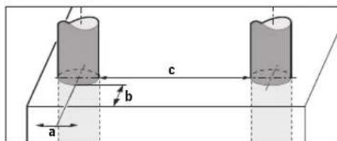
B) HbcaH oJIeMe MeHTyPiHe XeHe TaHaHdbIH MaTePnAbI MeH KyHHe 6aIINaHbCTbl
C)TeKaHaToK oTKi36eHIN lac naJa bOanDa, bipak KeBipk Xaardnapna epy HtHKecinHe Toe 0K13y KaOInerI naJa BOnby KyTneJi.
Onwey KpyanbHbH 3aybTTbK TAkTnuaaFb CepnBHK HEMpi (8) OHbyDpbc aHbKTayFa KEMeKTecei.
Taban KyiDpybc60nMaCa,enueyXHeaHbIKTay TepeHdiI dypbic 60nMaDbI.
Keepri CnHAnDbH eWey KpaBbHa acepi TeKcepeTIN KaBnaybcbHaFby yuH KyaTbHbE TESI TS 103 361 (V1.1.1) Tapay 9.4.1 d=60 MM HbCaH TepeHirimEn BemrIneHReKpTePmJxHe DeHreMeH TeKcepeDi.
Akaybikka Te3imdiniKcbHaBbyuHTeMeHderi wap KOnDaHbIaIbI:
Benrini wapTtapa (Mbicanb, 3neKtpocatnKaIbIK 3apdcb3aHMyece 3neKTPomarHHTTKepicTeKxykTenyi) enwey hntnxenepeine cepetiny MymKIN, afBmdaFbE nwey Hntnxenepi Kofanbin enwey kypabin 6atapnnapdb IbFabin KaHa opHaty apkbIn KaNbHa KeTTipy Kepek 6onybMYMkiH.
XnHay
Batapeanapdbicany/anMaTbipy
Oiwey KpaIbI yuiH aIkanHmapraHeu 6aTapecBn Hemece aKkymIaTOpbIH naiDaIaNHy YcbHbIaIbI.
BaTape6BnIMIHKaKNaFBH(4)awyWihbCbIpMaHb(5) KepcTeKiBaftbImEHacbH,6TaPae6BnIMIH KaKNaFBH anbTactaHb3.BaTapeHHHeMeCEakMyIaTOpbl canbH3.OcbHda nonIOCTapb 6TaPae6BnIMiHerI cypeTTe KepcTeInrReHdNpybIC6OByHaKe3KetK3iH3.
3apTay KyyHH HnHkAtopb (b) DnCnnneIeri (16) KofapFbky KJyKoNaFBHda BatapeaRanpBHy Hemece aKKMyrAToPnapBHy 3apTay KyHH KepeTei.
Hcyay:6ataperaapnblHeMeceakkymaTOpnapdbdep Ke3iHne aybictpy yuih aybcnabl 6atapera6enriche H3a3ap aydpabhl3.
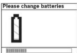
Диспейдe(16)<Please
change batteries>
(BaTapeJapdbi
aybICTbIbIHb13) eckepTyI
Kepcetince, petreyep
caKanbln,enWey Kypanbl
158|Ka3aK
ABTOMaTbI Typne eWIn Kanadbl. Elnweynerdi opbHday MmKIN hEmec. Batape Hemece akkymnTopnpabla aImactbPbHb3.
BatapeanapdbHemecAkkymyIaTnpapdbIbIbIpyuWih
6atape8eiminiHkaknafbIHdabfcypTekepcetireHei
6atapeHHbH/akkmyIaTOpdbHapKbJXaFbHa6acbHb3(1.).
6atape/AkkymyIaTOpdbHandbHfbJXaFb6atape
6eimineH(2.)axbpainbEidi6atapeHeakkymyIaTOpdb
Ohai bIbIpyfa6oanaDb.
Bapbik,6atapenernap HeMece akKymnTOpnpabi 6ipdeiAImactbipbH3.Tek 6ip eHdpyWihinKHe KyaTbI 6ipdeB6atapenernap HeMece akKymnTOpnpabI naDaanahbH3.
Onwey KypanbH y3aK yakBIT naDanaH6acahB3, 6ataperaHH HeMece aKKymnTOpnpabIe Onwey KypanbHaH bHfapbnAblHb3. Y3aKaYakBt KaTkaH 6ataperaNap HeMece aKKymnTOpnap TOT bacybJxHe 3apdH KOFAntybl MyMKIH.
PaiandaHny
Onuwey KypanbIH cbI3dAH XaHe TIKeNei KyH caynepeipHe caKaTahB3.
Θnwey Kpabiba anbkiu Tmemepatypa Hemece temepatypa Tep6nynepi acep etneyi Tnic. Temepatypa aibpmaibblktpabi yken 60nca,ohbi Kocy anbHda TmemepatpaTpcahin Tehciptipia. Aynbkua Tmemepatya Hemece Tmemepatypa Tep6nynepi ke3iHne enwey Kpablbihd andiir MeH dncnne KepecTeiui TeMeHNy MyMkh.
Θnwey KypanbHbH apTkbl XaftbHdaFb ceHCop aHaFbHa (9) eWkaHdA JxancbIpMaIap Hemece TaKaIwanaP opHaTnAb3. Ocipece MeTaIbbl TaKaIwanaP oJwey HtHexeepine acep etedi.
Xi6epyKa6dbkTapbH,MbicanbL,WLANUMTS,yuy paadapbI,paHnoJeHReKHeMece MHKpoToNkbHap cnAaTbI,kaKaBH KOpwaDa naJdAnany enwey fynKcncbHa acep etedi.
OJnwey HtHexeepHIn canacbI aphaBk Kopway
XaFdaBHnA TeMeHDeYi bKTHmAn. Bynapra, Mbicabbl, KYWIT3NEKTP, MarHNTHEMEc 3NEKTPoMaHT epiciH TYdbpTaBH KypandapBih XKaBihDbfBn, BinFaBbl,
MetanBb KaMTNtBn Kypblbc, pOnbrameOpanfah
Texey MaTePnAdepBnH, XKeH ToKtizetIH
TcKaFa3ApDnH HeMece PnNTkAnapBn, Bonybl
XaTadbl. Con yuHn Ka6bpfa, Tebe Hemece eEneHe
6yPbInay, apanay Hemece 4pe3aMeH eHcydEHN anbH
BaCKaMnnimet Ke3dePihe de Haazap aydpabHb3 (Mbicabbl, Kypblbc Xocnpapnb).
KymbicpekHmi(BcypetinKapaHb3)
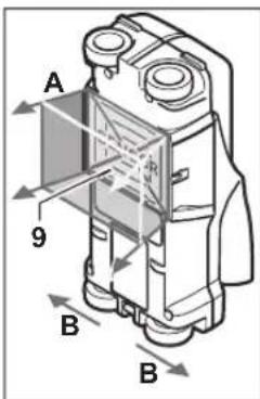
Oney KpaIbIme ceHCOPnap aMafbHbH (9)
actbHfB6eTIA eHwey 6aftbHnda Kepcetiriren eHwey Tepenirine dein Hekcpinei. hwey kypabih
B6aftbIMeH XblNkltKaHaJXaHE 10cmMHMaMnDaIeUwe KaWbIKTbIFbIHdFaHa eUwe MymKIN6oAdbI.
Onwey Kypabih Tpya a3 6acbl XblnKblTbHb3, dehrenektp 6ekem Ka6bipfara Thin Tpybi Kepek. Ka6bipfa
MaTePhaIbHaH aHbIpMaWbIbIbFb 6ap HbICaHdap aKbHdanaDb. DcNneJe HbICaH TepeHdi I XaHE MymKIn 60nc, HbcAH MaTePhaIb KepCetinei.
OHTaINbI eINwey HATNXepeine eINwey KaBbIKTbfI KEMIHDe 40cm BonFaHda Xane eINwey KypanblakbpHbYTH IN TeKcepiTeH JAAnda KblNkbTbINFaHa dn KKTiEneJI. FHKnraFbaMnaHbCTb peTte eINwey KypanblHbHpeketIH KeJeHeH KAtKaH HbCaHapDbH XOFapBfWETepinH eINWeMepe ceHmDi bonaBl.
Con yuin TEKcepietih aMakTbI apdaibim Kpct TAp3di XblkbltbIn TEKcepiH3.
ErepKa6bIpyda 6ipHeWe HbICAH 6ip 6ipiHIn YCTINDe KaTKAH 60nca, DnCnneJe KofapFbI 6eTKe eH KaKbIH XaTkaH HbICAH Kepcetinei.
TabinHan HbicaHbIH DnCnneJe (16) Kepcetiren CnattapbHaKaTb CnatapdaayBtKyb MyMKiH. Ocipece Kyka HbcanHapnneJe KaBhlbpak Kepcetinei. YIKeH, UINHdpNIK HbcaHdap (MbCaJI, nactHK HeMece cy Kybipnapbl) dncnneJe hakTb KyiHeh XhiJiKe KepiHyi MymKiH.
Ta6bInaTbHbicaHap
-ⅡnactNK Ky6bipnap (Mbicanblc, cy etki3eTIN nactNK Ky6bipnap, eENH mEH Ka6bipraIbIK Kxblity Kxynepe CnKtB, KEMIHDe 10 MM dHaMeTPMeH, 6oc Ky6bipnap KEMIHDe 20 MM dHaMeTPMeH)
-3NeKtpcBIMdap (TOK eTKi3eTIN He eTKi36eTIN)
- YuΦa3aJIbKcBIMapMbICaJIb,PiNTaYuIN)
Kiwi Kepheyni cblmap (MbicaIb, KoHbipay, Tenefoh)
-MetanIkybipnap, TaKTap, TacyuBnap (Mbicanbl, 60nat, MbIC,aHOMHHN)
- Apmatypalbik temip
-Afawbankanap
-6oc6eimep
OnweyTeMeHderineMymKIn60nabI
-BeToHda/6oNaTbIK 6eToHda
Ka6bipfana (kipniu, tecikti 6eToH, ra3dbi 6eToH, nem3a, i36cti Kym tac)
-ΓnncokapToHdbKKa6bipfpanapda
-CbIay,IIITKa,TyCKaFa3,napKeT,KINEM CnKtB6eTep aCTbIHda
-Afaw,rncokapToH apTbHda
Aipbikwa eIwey kafdainapbi
KaFbIMCb3 KaFdaInap enuey HaTnxecine Kepi acep etyi MYMKIH:
-KeiKaabTbI Ka6bpFapJap
- Boc nactnKy6bIpnap MeH KyblcTbIK aFaW apKaanbIKTapBtMeH rncokapTOH Ka6bIpFanap
-KabbpfandaKcbkTypFaHbicaHaDap
-blnranbkiabipfmaatepnanbl
-Metandb6eTep
Ka6bipyfadaFbkyiCTap; onap hbcHnap petiHe Kepcetiny MyMkiH
-KaTbMarHHTIKHEMee3NEKTPomarHHTIKepictepi TydbipatbIK KypbIFbInapFaXaKbH6Oy,MbICaJIb,YnblcTaHcunnapHEMee reHepaTopnap
Paindanahya ehdpy
Kocy/ewipy
Θnwey KypanbH KocyaH anDbH CehcOp aMafbHbH (9) bInran 60nMaybHa Ke3 XeTki3iH. KaKer 60nca, eNwey KypanbH Wsy6peKeH N KpyFaTbH cyptiH.
Erep enuey KypaIbI KaTbI TemnepaTypa 63repicinde 60nc aOnbIKocyuaH andbIH TemnepaTypacbIH Tehectpiik3.
Kocy
-Onuey KypaBnKocy yuiH Kocy/ewipy Tymecin (15) Hemece icke Kocy tyMecin (11) bacbH3.
- Kapbik IIObI (17) Xacbl TycneH XaHbIn, 6actanKbI kpaH 4cekyH iHHe dncnneJe (16) KepcetineJI.
-Erep 0Iwey KypalbImen 0Iwey opbHdamaCahB3 Hemece ew6ip Tymmei 6acnacaHb3, on aTOMaTTb Type 5 MHyTTan coe eWei PeTeynp Me3iPiHe ocb
Θwipy
-Onwey KypanbH eWipy yWIn Kocv/ewipy TyMecin (15) 6acblb3.
-0nuey KpyanbH eWipreHne 6apnbKa TaHaFa H peTeynepi M3iPnppe caKaTaIaBl.
CnHAn DbIbIcBIn Kocy/ewipy
CnHAn Db6bcI TyMecinH (13) KEMerImeH CNrHan Db6bcH Kocyfa Hemece 8iipyre 6oana. PeTeynp M3piHderi iki Ma3piHne
Oneey aici
Onwey KpyanbH KocbH3. HcnpneJe (16) cTaHapTbI Kepctinim 3kpaHb naJa 60ana.
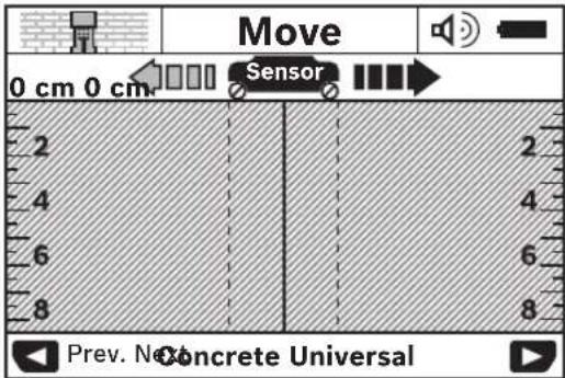
Oniwey KpaBbH Kabipfara opHaTbIn, OHbl K03FaBlc
6aftbIbMeH (KapaHb3, KymbicpeXHHMI (BCypetIH
kapaHb3), Bet 158) KaBpFadaH ATK31IN KxNkBiTBHb3.
Oniwey HtNkeepi 10 cm IaMaCbHdAbf MHNMaMnBik
KaBbKbTA DnCnneJe (16) KepcTeineDi. Dpybc enWey
HtNkeepie Xety yuH INwey KpaBbH TOnbIFMeH XHe
Kai KyTInRe HbCaHAp KaBpFA YCTHe HxNkBiTBHb3.
Erep Enwey KpaBbH ENwey KezHe Nde KaBpFadaH
KeTepceH3, Hemece 2 MNHyTTaY3ak NaDanaHbAcabaH3
(apeKet, nephe B6c) coFbI enWey HtNkeci DCnneJe
CaTaTaNb. CeHCopNbA aMak HNDNKATOpbHda (c)
(Kty) xAbapBo KcpCteineDi. Oniwey KpaBbH Kabipfara
KaTaNan HOCAHb3, OHbl ODaH api XblNkITcaHb3 Hemece
icke KocTymecin (11) baccahb3, enWey KaTaN icke
KocblNaBbl.
ErepKapbIKIIOBbI(17)Kb3blTynceHJkaHca Hbcah ceHCOPbIKaMakTa6oana. ErepXapbIKIIOObl(17) Xacbl TycneH JxHaCa, ceHCOPbIKaMakTa Hbcah 6oMaNb. ErepXapbIKIIOObl (17) Kb3blTynceH JxblbIKTaCa, ceHCOPbIKaMakTaKepeHyETki3etIH Hbcah 6oana.
KabipraHb6yfbinay,apanay hemece ppe3amen eHdeyeH andbin bacaaknapaKe3epi apkblkyainterpencaKaTahyibn3 Kaxet.Onwey Hntkelepihe Kopuaan opta acepneipi Hemece ka6bipra CnatablbknaneTyI Mymkh6bnkaHnndkaTop HbcnbeCencoAmaFbHda KepeTne caKayin TybHdabybl MyMKH (KapbIKIOB1(17)Xacbl Tycne HkaHaBbl).
Hdkatop 3nementepi (Acypetin Kapaib3
ErepceHcOpactbHaHbCaH6ap60nca,ceHCopaMaFbIHda (c) HINHKATOP naJa 60nAbl. HbcAan enIeMei Xane TepeHdiHie 6aNaHbCTbl MaTePnAn AHBkTAY MymKIn. AnbKaTaNFaH HbCAHHJXOFApFbXnerIe DeHHr HbcAH TepeHdiI (1) Ky konafbHaDA Kepctinei.
Hcykay: PyKcat etinre 6yPfnay TepeHirin H Kpcetkici (1) MeH MaTePhaI CnataB (m) ceHCopdaFb KaPa TycTe Kpcettinre HbcCaHa Heri3dienre.
HbCaH Maepnabl HndkaTopb (m) TEmeHderi CnnaTapdbkepceTei:
MaHTHITIK, MbicaIbI, apMaTypaIbI 60nat
MaHHTIK eMec, bipak MetaIbI, MbicaIbI, MbIC Ky6bIbI
160|Ka3aK
MetanbIeMec,MbicaIb,afuHHeMecePiactMaCCa
MATEPHAN cHnatabBenrini emec
Kephey etki3etih cbImap HnHkATOpbi (n) TEmeHderi cnnaTAPdi Kepcetei:
-TOKETKI3edi
Hcykay: TK 0TKi3eTIN HbCaHnpda eUkaHdaa KocBIMua CnnaTap KepcetImmeNi.
TexHKnblk Kytim XKHe Kbl3MeT
Kb13MeT KepcTeY KHe Ta3anay
- Θηωeу kypaŋbɪn āp naiŋdənaHáydaH 6þyɪbɪn TeKcepiɪz.
OJUeY KpaIbHbH, iHIne 3aKbIMnap Hemece 6oc 60neKTeP KePiHcH 6oNca, OHINXyMbICbC cHIMdi 60nMaHbl.
Kacbpi cHimdi Kymblc icTey yuH enuwe KypanbH Ta3a
KeHe Kypfak YCTaHb3.
Ouwe KypaBn CyFa Hemece Baca CytbKTapra 6atbpMaH3.
NactaHynapbIkypFAK,xymcaKy6peKeHN cyptiH3. Kfbl3aTAPbpHHeMeceepkITePn naDanaHaB13.

Kb3Met Kcpcty KaKaNafB(7) aApdaBIM
XaKcbi Ka6bIraHbIN TEKcepiH3. Kb3Met
Kcpcty KaKaNafBIn TEK Bosch 3eKeTp
KpaIaDapbHbH EKInTe K3Met Kcpcty
opTaNfBbAawbyMymKinH
Onwey KypalbH TeK XeTkiinreH KopraTbH Ka6bHaCaKaTaH3 HeMeCe TacbMaJaHb3.
KeHney yin Hneey KypanbH Kopfay KaTacbHaKaIepiH3.
TytbHybIfa KbI3MeT KepcTeY XHe naIdaIaNy Kehectepi
Kb3met Kepcety We6epxahacbI OhmDi JxHNey XHe KYTy, coHaan-ak KocAnkbl 6nWeKTeP TypaIbI CypaKTapFaXayan 6epei. KapbIy cy36bnapbI MeN KocAnkbl 6nWeKTeP typanbl mAmimetepdi TEmHderi MeKeHHkaJaTa6acbl3: www.bosch-pt.com
Bosch 6aFapIamacbKeHcTob6bi3iHemdepXHe OanapblKepeK-kaapKaTpbyTypaBlycpaKaTpbl3faXayan 6epeji.
Cypakap KOKO XHE KOCAKbI 6eIIueKTEpre Tancbipc 6epy KeiHde MInTeTI TypEeEHIMDl3ayBtBk TaKTaWacbHdaBf10-caHbI eHIM HEMipih Ka3bHb3.
OhdpyTtanaTaptbMeH HopMaapbIbHcKaTanybMeH 3nEeKtp KpaBbH KHeHey KHe KeiNdi Kbi3MeT KepCteTy 6apbIK MemKeTep ayMaftbHaTeK "Poept B0w" HpMaBbH HeMece ABTopHaunFaHfA Kb3MeT KepCteTy optaBkTapbHaOpBHaDaB.ECKEPTY!3aHcb3X konMeH aekinireh eHimdepni NaDanahy Kayinti, deHcaynbfbHb3fa 3HH KENTipyMmKIn. OhImepDi 3aHcb3Xacay XHe
164 Romana
TapatyekiminiikxaneKbIMbIcTBkTepin6oHbHua 3aHMeN KydanaHaDb.
Ka3aKCTAH
TybHybIcapFaKeHec6epyKaheWafBIMapDbKa6blnay optanblfbl:
"PoBept Bow"(Robert Bosch) KUIC
AJIMATbIK
Ka3aKCTaH Pecny6nKacbI
050012
MyparbaebK.,180y
"RepMec" BO, 7 ka6aT
Ten.: +7 (727) 331 31 00
ΦaKc: +7 (727) 2330787
E-Mail: ptka@bosch.com
CepBntKk3MET KepCeTy opTaNbIKTapbMeH Ka6blIay nyHKTePiH MeKeH-KaMbI TypaNb IToNbIKKaHe e3EKTi aknapaTb Ci: www.bosch-professional.kz pecmN caTTan ana anacbi3
Kadere kapaTy
Oney KpyaBn, AkkymTOpbH/6aTapeNaPbH, OHbH Ka6bIKTapbMeOpamacBH KopwaaH opTaHb KopFaHTbH peTe KeereKapatyOpbHaTancbipyKaKeT.

Oniwey KypanapbH kHe aKkymyIaTOpnpabI/ 6atapeepnapbl ykOKbcHa TaTaMaHb3!
Tek KaHa EO endepi yuin:
Eypona 2012/19/EU epexeci bohihwa japaamcb3 eniwey Kypaandapb khepe Eypona 2006/66/EC epexeci bohihwa 3aKbIMdIahn Hemece eckkkymnyTOp/batapennap 6eNek KHHaBn KaDere JapaTbNykaXET.
Româna
Instruţiuni de siguranta

Service sculelectric
Strada Horia Macelariu Nr. 30-34, sector 1
013937 Bucuresti
H3no3BaHe/cmHa Ha 6aTepuHte
PpenopbUba ce 3a pa6oTa c H3MepeBaTeHnIypeI da ce non-3BaT aKaklHO-MaHraHOBu 6aTeepu nnAkyMylaTopn.
3a OTbapnHe Ha Kanaka Ha The3dOto 3a 6atepnn (4) HATNC-Hete 6yToHa (5) B NocOKATA, yKa3aHa CbC TpeNkA, H MAXHE-Te Kanaka. IocTabete obHKHOBeH INN AkymyIaTOPH 6atePNn. PnTOBa BHIMaBAte 3a npaBnIHATA NOJIpHOCT CbIacHo N3o6paKeHHeTO B The3dOto 3a 6atePNn.
CMBONbT3a6aTePNB(b)Ha rOpHnPeD3aCbCTOHNHeTo Ha ypeDaHa nCINPnEe (16) nOKa3Ba CTeNEHTa Ha 3apeDeHOCT Ha 6aTePNHe,peCn.Ha akymNaTOPHNHe 6aTePNn.
Yka3aHHe: CneTe Te npomHaTa Ha cHbOJa, 3a Da 3aMeHrTe 6aTePHnTE, pecn. akymyIaTOpHnTe 6aTePHn CBOeBpeMeHNo.
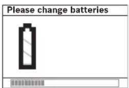
AkoHaDcPnE16)ce noKaXe npdynpExdHEnTeo
KINOBA.He e Bb3MOxHO No-HaTaBtHHTO H3BbPbBaHe Ha N3MepBaHH.3aMeHETe 6aTePHNTe,peCn.akymyIaTOpHNTE 6aTePHN.
3a n3BaXdahe Ha 6ateHnTe, pecn. akymyNatopHnTe 6ateHH, HATNCHEte 3adHnKpA HA HnKoR OT 6ateHnTe, KaKTo e NOKa3AH Ha fHpyata Ha KANaka HA rHe3dOto (1.). PpeHnRT kpaH Ha 6ateHnTa/AkymyNatopHnTa 6ateHnCe OCBOxKaDaBt O TDeJIeHNrTo 3a 6ateHn (2.), TaKa Ye 6ateHnPa, pcn. akymyNatopHnTa 6ateHn MoKe IeCHO Da Ce n3Ba- dN.
BHHaHmCmHaJIte BCnKb6aTePnH,peCn.akymyNaTOPnHTe 6aTePnEeNHOBpEmHeNo.H3noJ3BaIte cAmo 6aTePnHnn aKymyNaTOpH6aTePnHa eHN npon3BOHITeN C eEdHaKbB KanaunTeT.
Korato HMaJa H3NONBATE H3MepBATEHnHa ypei npOdbJnxHTeNo BPeMe, H3BaXdaTe 6aTePHte, pecn. akymnatopHtSe 6aTePHn. Ppi npOdbJnxHTeHnO
cbxpanhaBHe BypeJa 6aTeepHnTe n AkymyataOpHTne 6aTePnMoT Ja KopoDnpat N da Ce caMopa3peJr.
Pa6ota
Pepnna3BaIteH3MePbATEENHn npH6OpOTOBnAaKHaBAHe HdpeKTHo NOnaDaHe Ha CbHuEeBn Pyu.
He n3naraTe H3MepBaTeHnna ypeHaekCTpeMHn TEMnepaTyPhnHn pe3KN TemnepaTyPhn npomEnn. PnHrTolemn TemnepaTyPhn pa3NKn H3uKaAteYpeBbT da Ce TemnepHpna, ppeHn da Ro BKlnouHTe. PnEckTpeMHn TemnPaTyPhn Hn pe3Kn TemnPaTyPhn H3MeHeHn ToHocTtHa H3MepBaTeHnna ypeHn H3o6paKeHneTo Ha DCINIE MoT a Da CE BNOwAT.
He nocTabrae neneneHKn H Ta6eKN B 30HaTa Ha Cen30pa (9) Ha rpb6a Ha n3MepBaTeHNH ype. Ta6eKn OT Metal (metan) BnnaT CNHHO Ha pe3yntaTne OT n3MepBaHETO.
PpoecbHa H3MepBaHe MoKeJa 6bDe IOBnHnO t pa6oTaB 6nh3ocT Ha H3NbUbaaHpaNOBbHn yctPoHCTBa,Hanp.6e3KHN MPexOBn yctPoHCTBa, UMTS-ycToPcTBA,Bb3dyuHn PaapH, npedabaua aHTehn HNN MKNPOBbJIHOBN FyphH.
Popadn npnncnna ha pa6ota pe3yntaTbT ot H3mepBaHeTo ce BnHReOT ONpeDeEnn npaMeTpHa OOKnHaTa cpeA. KbM TxCe pnuChnBat Hanp. 6n3ocTtHa ypei, KOnto rHeepnpat CnHNo eKeTPuecko, MaHHTHO HnEeKTPomarHTHO NOle, BlaXHoCTTA, HAnuHeTO Ha cbDbpxaun Meta CTPOENTHN EmeHTN, KaUnpaHn C anyMNHeBO FOHNO H3OnauHNN MaTePhaN, KaKTo N TokOpOBExDaU TanETn HnNnOouKn. PpeDn da zaoHte np6nbAhe, pa3p3BaHe nn Phe3ObaHe B CteHata, Noa Hn TaBaHa, ce ocBeDoMeTe n OT dpYrH n3TouHnU, (Hanp. cTPOENTnPiNaHOBe).
HaHH Ha fynKuHoaHpaHe (Bx. fHr. B)
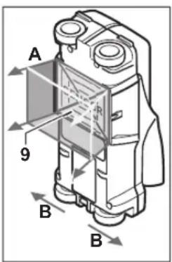
Cn3mepBaTeHHy ypeI ce npOBeRbA oChOBaTa B3oHa-Ta Ha cEH3OpHte (9) no HanpabNeHHe HA n3mepBaHTo A do nocOeHATA bIb6OuHn. N3mepBaHTo E b3MOxHO camo npn npMeCTBaHe Ha n3mepBaTeHHy ypeB nocKaTa, 03HaueHa c Bn npn HmHaBaHe Ha MNHMnHo pa3ctOHHne ot 10 cm. PnH-BNXBaHTe N3mepBaTeHHy ypeD BNHaHn No npBaVA HHN C neKo npNTnCKaHe KbM CTeHaTa, Taka Ye KOnEnata
Ja KOHTAKTYBAT CHRyphO C Hea. Pa3No3HaBAt ce 06eKTH, KOHTo ca OT MaTePhAa, pa3NHeH OT To3n Ha CTeHata. Ha DcCnIeCe yKa3Ba Dbl6OuHnAha Pa3No3HaTHn 06eKTH, Ako E Bb3MOxHO, MaTePhAaBT My.
OnTHMaHnpe3yIaTn ce nOlyuBaT, aKo OTceUkata, no KOrTo Mepnte, e Hau-MaIko 40 cm n H3MePbATEJIHHrT ypeD CE npEmecTBa 6abNO no UraNATA n3CneBdAha 30Ha. Nopadn pInHua Ha DeiCTBHe HaDeEJHO ce OTKPBAt p6OBe Ha oEkTu, KOTo Ca HanpeH Ho Ha HapBaIeHHe To npEmecBaHe Ha H3MePbATEJIHHrY ypeD.
3aTObaBHHaHnPpemHHaBaHTePpe3HcneEBAHaTa 30Ha B DBe B3aHMHO nepneHnKyIpaHn HappaBHeHH.
Ako B cteHaTMA HraKoJIko pa3nONoXeH eINH HAnDpyr o6ekTa, Ha nCnpea ce h3o6pa3raBa Hau-6nH3KnT Do NOBbP XHOCTTa.
Ioka3BaHHTe Ha nCnner (16)Ha ypeDa CBOCTBa Ha OTKPNITE oBekTH MoRt Da Ce pa3nHauBat OT DeHCTBNTENHTE CBOCTBa Ha oBekTA.CneuHaHO MHOro TBHKn OBekTH CE H3Opa3aRbTa Ha nCnner C NO-ronMaDe6EHHa. No-ronEM UHNHPrHnO bekTH (HaP. INaCTMacOBn TpbHn BO-DonpOBoD) MoRt Da Ha nCnner No-TECHN,OT KONKOTO Ca B DeCTBNTEnHOCT.
OTKpHbAeMH o6eKTH
-Пл actmacOBHtpb6H(haip.ПлactmacOBHBOOIpOBODHn Tpb6H,KATO NOIODOB HINCTEHNOOTONNEH N.T.H.C MHNMaJIeHДHAmETbp10mm,PpA3HnTpb6HcMHNMaJIeHДAMetbp20mm)
-Enektpueeckn npoBoHnU (He3aBncMo daHn ca nOHa npneKeHn Hn He)
- Tpna3HH eneKtpnpoBOHn (HaNP. KbM MoUHN KOHCyMaTOpN KATO KOTNI Hp.n.)
Cna60KOBn npoBDHnU (Hapr.3a 3BbHeu,Tepeoh)
-MetaJIHn Tpb6n,MetaJIHn ⅢaHrN,MetaJIHn TpeReepn OT BcKaKbB BnD (HaPiC. CTOMaHa, MeI, aIyMHHn)
-ApMnpoBbUHa CTOMaHa
-ДьрБЕнИ ГпДи
KyuHHH
H3MepBaHeTo e Bb3MOxHO
-B6eTOH/CTOMaHO6eTOH
-B3napn(tyxnn,nopect6eToH,neho6eToH,nem3a,BaPobwK)
-BCTEHNOTJIeKNTPOINTeHnMATEPHaHn
-NOJ NOKPHTH N NOBbpxHOCTHH CIOeBE KaTO 3aMa3KN, NIOUKN, TANET, NapKET, KINHM
-3aDbPBO,rHnC-KapTOH
CneuaJIHH H3MePBAHn
Iopadn npHnuaHa nHa 3MepBaHe cbseCTByBat He6NaorponpTTHN 6OToAeTcBA, KOTo MoT aDa BNoWat TOHOCTa:
- Ckpntn Tpnn3MePH KOHCTpykTHBHN eJeMeHTN
-ПраЗн плacrмocи Тьби Идрбен Грд В Кухи npoctpaHCTBaИ Стени OT lekn CTponTeHH MATEpnaJI
-06eTK, KOHTO ca pa3nIOJXeHN KOCO cnprMo CTHeHaTa
-BnaxHa CTeHa
-MetaHHIOBbpxHocTH
-KyXHHBCTeHaT;TeMOraTa6bDAtH3o6pa3eHN KATO 06eKTH
-5n3oCTdo ypeDn, KOHTO cb3daBAT CnHnMaHHTHN HnneKTPOMaHTHN NOIeTa, HAp. 6a3CHN CTaHnHa Mo6NIH TeneKOMyHKauNOHm MpeXn
IyckaneBeknnoataa
BKnIOUbaHe H N3KIOUbaHe
PepnBkNoUBaHe Ha H3MepBaTeHHN ypeI ce yBepeTe,ye cEH3OpHaTa 30Ha (9) He e BnaXHa. Pnp Heo6xoDnMOCT NocCyWeTe ypeJa C MeKa Kbpa.
Ako ypeBt e 6nn noJnoKeH ha pe3Kn TEMnpaTyPHn npomeHH, ppeH da ro BKNIOHTe, roocTaBeT da ce TEMnpHa.
BknIOuBaHe
-3a BKNIOUbaHe Ha N3MepBaTeHnHapei HaTNCHeTe NycKO-BBn PneKbCBaU (15) HN CTapT 6yToHa (11).
-CBetoHOBt(17)CBETBa3eEHO3a4sHaDnCn-(16)ceH3o6pa3raBaHaayannHHTekpan.
-AKHe H3BbPbATEH3MepBaHnH He HaTHcHETe 6yToH, H3MepBaTeHNHTypeC H3KNIOBA ABTOMaTHHO CNEd 5 min.B MeHIO HAcTPOKNMOKETe Da IpOMeHNTe TOBa
N3KIIIOUBAHe
-3a n3KJIOUBaHe Ha n3MePbATEHnYpeD HATNCHTe NycKOBnI pKeBcBaay (15).
-ПиИЗКИLOУBAнHaИЗМерВATEHЯурсЕЗANA3ВАВ BCNUKINACTpOKNHAMeHIOTaT.
BkIIOUBaHe/N3KNIOUBaHe Ha 3ByKOBaTa CnHannHaau
C6yToHa3ByKOBcHnHa1(13)MOxTe DaBKnIOuHTeNINHnIKIIOUHTe 3ByKOBaTa CnHnHa3aun. BMeHIO HAcTpoKN MoKeTe BNoDMHeo
№MepBaHe
Bkniouhe N3MepBaTeHnHrype. Ha nncnner (16) ce n3o6pa3ra BcTaNapTHnRTekpah.
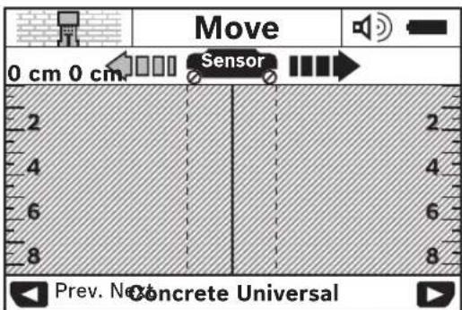
IocTabete H3MepBatenHn ypeHa cteHata n ro npemecTe B NOCOKATA Ha DbHXeHne (Bk. .Haunn Ha fynHKuHOHaPHe (Bk. fng.B), CtpaHua 174) had cteHata. Cede Kato 6bde H3MNHTO MmHMalno paoTOnHne 10 cm peyntaHTe OT H3MEpBaHeto Ce H3o6pa3raBt Ha dncnner (16). 3a da noLuynte Bepn pe3yNTaTH, npemecTaTE H3MEpBATENHn ypeBabHo n HAD CEINH npeDnonaraem oEeK TcHetaTA.
Ako nBpeMe Ha n3MepBaHe OTdJIeHTe N3MepBaTeHnHa ypeDOTCTeHATA HnHE ro nON3BaTe 3a NOBeue ot 2 MNHytn (npe
176|bIrapckn
MeCTBaHe,HaTnCKaHe Ha 6yToH),Ha DnCnner ce 3ana3Ba pe- 3yNTaTbT OT NocneDhOto H3MepBaHe. B 3oHata 3a ceH3Opa Ha DnCnner (c) ce H3NtCBa Cbo6uEHHeTO
Ako CBETOIOBt (17)CBETHE C cepBeHa CBETINHa, B 3OHa- ta Ha CEH3OpTE Ce HAMnpa OTKPHT OeKT. AKO CBETOIOBt (17)CBETN 3eNEHO, B 3OHaTn HA CEH3OpTE HMA OeKT. AKO CBETOIOBt (17)Mnra C cepBeHa CBETINHa, B 3OHaTn Ha CEH3OpTe Ce HAMnpa oEKT NOEeKTPnuecko HanpeKeHne.
PpeHn da 3anoHete np6bHahe, p3aHe nHn fpe3oBaHe B cTeHa, Tp6Ba da ce HnHOpMnpate H ot dpYn N3TOUHN 3a HANHHeTo HA ONACHOCTN. Tb kato pe3yIaTHte OT hMEpBaHeTo MOrAT da 6bDaT NOBnHn OT OKONHaTa Cpea HnC TpyKtypaTa HA CTeHaTa, e BB3MOKHO Da CbIeCTByBa ONACHOCT, BBIpeKeH Ye Ha IINcIIe He Ce N3Opa3raBA oBeKT B 3OHaTa Ha CEh3opa (CBeTOnIOBt(17) CbETn Cbc 3eNeHa CBETInHa).
ElenentHaHcnnner(BK.ΦnA)
Ako noi ceh3opa ce hAmipa o6eK, toi ce n3o6pa3raB b O6-actTa (c) ha DCnner. B 3aBNCmOCT OT rOenMHATA N dbIbOuyHATA Ha o6eKa e Bb3MOXHO CbIO TAKa H pa3IO3HaBaHe HA MaTePnHa My, Dbl6OuHATA Ha o6eKa (I) DO rOpHnMy Pb6 ce Noka3Ba Ha peDa 3a CbCToAHneto.
YkaaHHe: Poka3aHnraTa 3a DoNyCTmMa Ta bIb6OuHa Ha npoBnBaHe (I) n 3a BnDa HA MaTePnAna (m) ce OTHacATdo N306pa3eHH B UepHo 06eK T 3oHaT a H cEH3Opa.
Poka3aHnTa 3a MaTepHaNa Ha o6eKaT (m) MoRat da 6bDat:
MaHHTHH,HaP. apMPOBbUHa CTOMaHa
HemaHHTHNHOMeTALHHaNp.MHaTtpb6a
- Gal HemetaH,HaP. DpbBO HnI nIaTmCa
BnBbHa MaTePnae HEN3BeCTeH
Iokaahnra 3a eektpnueckn npoBODHn (n) Moat Da 6bDat:
- Yka3aHHe: Pn o6eKTH nOJ eNEKTPnuecKO HanpeKeHHe He Ce NOKa3BaT dpyr TExH CBOICTBa.
HannneToHa HanpeKeHHe He MoKe Da 6bJe yCTaHOBEHO eHNo3HaHNO
Yka3aHHe:B HnKoN CnyuAn IPOBODHNuHa TpHpa3eH ToK ce pa3no3HaBAt KaTo IPOBODHNu, NO KOnTO HMa HAnpeXeHne.
OnpeenHeTo Ha CBoHCTBTo "eneKtpoPBOOJaM"MOKe npn BnCoka OTHocHTHa BlaXHoCT Ha Bb3Dyxa (>50%) da e CnHO OrpaHueHO.
IokanH3npaHeHa 06eKTHTE
3a lokaHnHaHTo Ha o6eKHTe eIOCTaTbUHO eNHOkpaHoTO IpemHHaBaHe HAD TAX.
Ako He OTKpHe Te oBekt, NOBTope TnpOBepkata Ha CbItoMRCTO B nepENHnkyIaPno HapPaBnEne (Bx. ,HaunHaФyHKUHOHaPAne (BX.ΦnB.B),CTpaHnua 174).
Ako nckaTe da noKaunn3npate tooH no ot6eKeHte macto To hOtKpHT o6eK, BbPheT H3MePbaTeHHy ypeD ha3aJ.
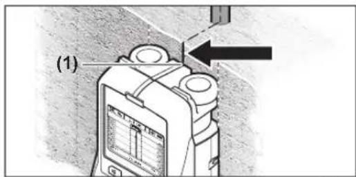
Korato obektbc H3o6pa3n IIOI ueHtpanHata nnHn (k) HaDCINNEA (16), c NOMOHTa Ha TropHna HAppe (1) MoKTe Da HAHeceTe rpy6a MapKnPOBa. Bce Na Ka3n MaKpOBKa e ToHa cAmo Ako obektbepa3noJxeh CToPo RBeTnKaIIHO, TB KaTO 30HaTa Ha ceH3opa Ce Hmnpa ManKo PoD TropHna HAppe 3a MapKnIPAhe.

3aTOHOTO O3HaUaBaHe Ha r6apHTne Ha o6eKa TIpemecTe H3MEpBaTeHnH ypeH hAraBO HnHnAraCHO,doKATO o6eKbT 3actaH NOBbHnH p6.HanPmep ako o6eKbT 6bIeN3o6pa3en HA DCnPiE (16) UcHTpAnHO nOu PPhXOBaHaTa DnCHA NHHg (g),MOKeTe Da ITo MapKnPaTe TOHNO No DecHNHaPe3 (3).
Pa3noJooKeHHeTo Ha OTKpHTHa 6oekt B CteHaTAt MoKeTe Da yCTaHOBInTe, KATO IpeMnHEc Cypeia No HAKOJIKO OTMeCTeHN eHdA CnpMa Dpyra OTCeUKN (Bx. fNur. I) (Bx. ,PiPmepn 3a peyntaTH OT N3MePbAhe", CTpaHua 178). MapkpauTe n CbeDnHETe CbOTBETHTE TOKKn.
C HATNCKaHe Ha 6yToHa CTApT (11) MoXeTe Da N3TPnTe OT DnCIIe NOKa3AHnTa 3a OTKpNTte ObkTN Da 3aNoCHHe HOBO N3MepBaHe.
CmHa Ha pexkMa ha pa6oTa
C 6byToHnTe 3a H36op (10) n (12) MoKTe Da CMeHrTe pa3-
-3aДаИЗберетe сдБацьпpeжмHa pa6oTa,HaTHСHTe KparKOTpaHNo 6yToHa 3aИЗбop(10).
-3aДаИЗбетепрдхODнг ржм Ha pa6ota,HaTNCHeTe KpaTKOTpAHO 6yToHa 3aИЗБOP(12).
Upe3 n3bopa Ha pexHM Ha pa6oTa moKeTe da hAcTPOte H3-MepBaTeHnHa yPeD 3a pa6oTa cbc CTehN OT pa3nHu MATEpHn. TekyIurat peKmCe H3O6pa3Ra HeIpeKbChato B3OHATA (h) Ha DCnPnE.
(BetoH yHbepcane) (npeBaPteHno Hactpoen)
Pa60THrTpeKHM
(BeToH BnaXeH)
Pa60THHrpeKHM
Mon,OTHTaIte,ue6eToHbTceHyxJaeeOT HAKoKO Meceua 3a IIbIHOTo CN HcBxABaHe.
(BeToH cneuMaJeH)
Pa60THnTpeKHM
Ako ypeBt NOKa3Ba TBbpIe MHOro 06ekTH, e Bb3MOxHO da ro npnDnBkBaTe HENOCpeDCTBeHO Ha apMnPOBbueH npbT ycnpoepHo HA Hero. B TaKb Cnyau OTmecTe H3MePbAten Hya peHa HAKO KaHTmETpa BCTpAHn ONITaTe OTHOB.
(Панелно отоненье)
Pa60THrTpeKHM (PAnenHOr otOnnHeH) e CNEuaIHO npedHa3NaueH 3a OTkpBaHe Ha metaJIHH, KOMno3HTHn HA metaIHa OCHOBa H3aBnHEHc BODa nactMacoBH TpbH n eneKtpueckn npoBOHNu. Ppa3Hn nlaCTMaCOBH TpbH He ce OTkpBAt. MakcmaHata dbbOuHa Ha n3MepBaHe e 8 cm.
(Cyxo ctpontenctbo)
Pa60THHrpeKHM (Cyxo cTPONTenCTBO) e noiXoJH3aOTkPNBaHe HaDbPBENI rpeHN MeTALHNbPjAHN HneKTPnueckn PpOBDoHNu B CTeHN, H3pa6OteHN Upe3 Cyxo cTPONTeNCTBO (DpBPO, HnckapTOH nDp.). 3aJIbHHeHN pAACTMacOBn Tp6Bn HdbPBENI rpeHN Ce H3o6pa3ABAT NO EHN HcBt NaHIN. PpaHN IAACTMacOBn Tp6Bn He ce pa3No3HabAT. MakcmaHnata Dbl6OuHn HA n3MepBaHe e 8 cm.
(MeTan)
Pa60THHr pexHM (Metan) e noxOJaI 3a oKpHBAhe Ha metaJIHn OBekTN n eneKTprueckn npoBOHNu nOHa napeKeHne, KOrato dpyrHTe peXHMn Ha pa60ta npn pa3LIHHn BapnaHTn Ha cTeHnTE He DaBAt 3aOBONHeHn pe3ynTaTn. Bno6Hn Cnyaun npn No3BaHe Ha To3n peXHM Ha pa60ta yBCTBntENHOCTTa KbMa pa3No3HaBAHe Ha o6kTu n O-ToJMA, Ho TOUHOCTTa e NO-MaJa.
CTeTeHtHa OTKPbBaHe MoKeJa e CnHNo HamaJIeHa Ipn BnCOKa OTHCHTENBA BnaJXHOCT Ha Bb3aYxa (>50%)
(Изгелд ha carhan)
Pa60THHrPexHM
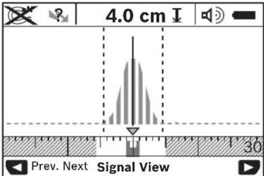
ToKaHa Ha anekca Ha Kpmbata Ce npedCTab B mAbk Maa6bHa nncnner Ha pa6oTHna peKHM (h) B U-06pa3Ha fOpMa. Poka3Bat Ce nb6OuHa Ha o6eTa N DOKoNtO e Bb3MOxHO CBOCTBa Ha MATEPnA. MaKcMnHata Dbl6ouHa Ha H3-MepBaHe e 15 cm.
CnataHa CnHana He MoKe Da 6bDe yKa3aHHe 3a DbN-60uHata Ha o6eTa.
CmHa Ha n3o6pa3raBaHaTa HhΦopMaun
YkaaHHe:CMHa Ha H3o6pa3BaHata HhOpMaun e Bb3- MoKHa BB BCNUpeKMMHa pa6ota.
HaTNCHe npOdbIaKHTeHNO 6yToHnTe 3a H3bOp (10) HII (12), 3a da npeBKnIOuHte OT cTaHdApTHnE ekpaH haek paH pyNETka.
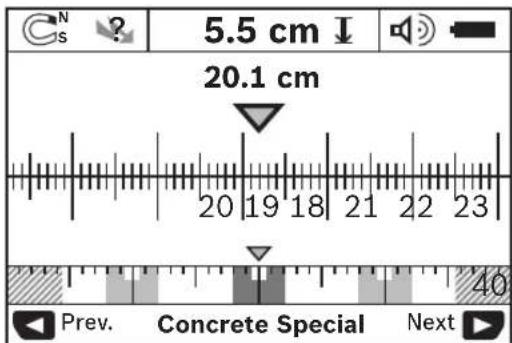
HaФг. De nokazan npnmepeh ekpan tnpyntka: Ha Hero ce BnKdT pnc CTOMaHEn apMaTyPi Ha paBn pa3ToHHa. B To3n peXm MoKe da Ce onpeEe nn pa3ToHHeTO MeJky HamepeHte 06kTH.
178|Блгарский
IpoI noneto 3a IbIb6OuHnata Ha o6eKa (I) ce H3o6pa3raBa n3MnHaTHr OHTaHauNTo HA H3MePBAHeTO nbT, Ha NOKa3aHnnpHmep 20.1 cm.
Ha mankata MeptenHa HnHna Hnd noka3aHneTo 3a peKnMa Ha pa6ota (h) Tpnte OTKpHTN o6ekTa ce H3o6pa3RbAT KaTO npAbOBgblHnU.
YkaaHHe: NokaHaHTa 3a DoNyCTMaTdaBb6OuHa Ha npoBaHe (I) n 3a BnDa HA MaTePnAna (m) ce OTHacr do H3oPa3eHn B YepHo 0eKb B 3ohTa HcEH3Opa.
3a da ce BbpHeTe KbM cTaNapTHnE kpaH, HATNCHe TkpatKOTpaHNO HrKOI OT 6yTOHnTE 3a N36Op (10) HIN (12).
Yka3aHHe: Cmehr ce camo BnDa Ha n3o6pa3raBaHe Ha H-ΦopMaIHTa, He npeXIma Ha pa6ota!
Meho HactpoKu
3a D BnE3e B MeHIO HAcTpoKn, HAtNCHe 6yToHa (14).
3a da n3ne3eOT MeHIOTo, HATnCHete 6yToHa CTapT (11).
H36paHHTe Do MOMENTA OIaHc Ce 3ana3BaT. AKTHBnPa Ce CTaHdapTHHaekpah 3a peKHM Ha H3MepBaHe.
Habhrpane B MeHIOTO
HaTCHete 6yToHa 3a HactpoiKn (14), 3a da ckponipate ekpaHa Haonly.
HaTnCKaIte 6yToHInTe 3a n36op (10) n (12), 3a da n36npate CTOnHOCTN:
-C6byToHa3aH36op(10)H36bnpateJraChata,pecn.cneBaIaTaCToHocT.
-C6byToHa 3a n3bOp (12) n3bnpateIyBaT, pecn. npedXoHATA cToHocT.
(E3MK)
B MeHIOTo
(Bpeme Ha n3KnouBaHe)
B MeHIOTo
(Ocbetbahe Ha ducnne)
B MeHIO TO
(apkoct)
B MeHIOTo
(3BykoB cmHan)
B MeHIOTo
-Ппсдваретндахсторкe
Ha 6ytoH KOrato B3oHaTa Ha CeHc0pa 6bJe OTKpnt oBeKT. BdoBnHeHne npn OTKpNBaHe Ha npOBODNk POp HappeKeHne Ce n3daBa YecTo NOBtApAa Ce 3ByKOB CnHaI.
-Ako 6bIe H36paHa CToHnOCTa
-Пин HabtpoKata(Keyclick>(UpaKaHc c 6yToH) ce n3-ДаВа 3ByKOB CnHaJ CamO Пин HaTnCKaHETo Ha 6yToH.
MeHIOOnbHHHTENH NaCTpOKn
3a da Bne3eTe B MeHIO DoIbHnHTenHn HAcTPOKn, npn H3KIOueH n3MepBaTeH eyped HATNCHe eNHOBpeMeHHo 6yToHa 3a HAcTPOKN (14) nIpyCKOBnPiEkbCbau (15).
3a da h3ne3e OT MeHIO, HATNCHEte 6yToHa CTAPT (11).
H3BbPweHHe NaCTPOIKn Ce 3ana3BaT n Ce AKTHBnPa CTAH.
dapTHNt EKpaH 3a peKHM Ha h3MePBAHe.
Habrnpahe B MeHIOTo
HaTnCHeTe 6yToHa 3a HAcTpOuKn (14), 3a Da CkPOnIpaTe ek paHa HaDony.
HaTnCKaIte 6yToHInTe 3a n36Op (10) n (12), 3a da n36uPate CTOnHOCT:
-C6byToHa3aH36op(10)H36npaTeIaChata,pecn. cneBaaata cToHocT.
-C6byToHa 3a H36bOp (12) H36bnpate IaBaTa, pecn. npenXoHaTAtcOHHocT.
(HnΦopMaunz3a ypeDa)
B MeHIO
(BpeMeHa pa60Ta).
B MeHIO
PpHmepn 3a pe3yntaTH OT h3MepeBaHe
YkaaHHe:BnpMepHTeNo-DoIy3ByKOBnTcHHaHaH3-MepBaTeHNH ypeE BKnIOueH.
B 3aBNCMOCT OT rOJEMHnHa T NbIb6OuHnHa HAHAMpuAe Hc B3OHATA Ha CEH3OpHTe OBeKT He BnHaH e Bb3MOKHO da ce ONpeEN DaHn TOBa e npOBOnHK NoI HAnpeKeHHe HnH He. B TaKB CnyaH CNMBonbT ? Ce Noka3Ba Ha HHnKaTo- pa (n).
IpoBODHnK nO HAnpeXeHenHe (Bx. fHr.C)
B30HATA HcEH3OpHTe CeHAMPMeTAnEh 06KTnOHNappeXHeH,HAnp. EEnKTPuYeCKN pPOBoHNIK.DbIbOuHNaHa 06kTa e1,5cm.H3mepBaTeENHrATypeDn3DaBApneDyn
peHTeHHa 3ByKOB CnHAn 3a npOBoHNk NOp HnpeKeHne,
om TaKbB 6Be peHCTpnpaH OT CEH30pa.
Jen3haaHaRa(Bx.ΦnR.D)
B30HATA HA CEH3Opa HMA MaHHTe HOBKT,HaNP. CTOMaHEH npbT.BnBO N BACHO OT Hero HMA npyRn O6EKN 3HBN 30Hata Ha CEH3Opa.DbIbOuHHATA Ho 6EKAe 5,5 cm. M3MepBaTeHNHRTypeH3MbUBA 3ByKOB CnHAn.
MeHaTpb6a(Bx.ΦnR.E)
B3ohata Ha ceh30pa Hma MetaIeH o6ekt,HaP. MeHa Tpb6a.ДьБочнATA Ha o6ekt a 4 cm.ИЗмepBaTeHnHrt ypeI n3bYBa 3ByKOB CnHAn.
PiactmacOBnnnDpbbeno6eK(Bx.ΦHr.F)
B3ohata Ha ceh0pa Ce hAmnpa HemetaeH o6ekt. Toba e 6bn3bk DO nobpxhoctTa nactMacOB nIbpbbeH o6ekt. N3mepBaTeJIHHT ypeD n3nbVBA 3ByKOB CnHAn.
ObTeHaTnOBbpxHocT(Bx.ΦnG)
B3ohata Ha ceH30pa HMa metaJIe H o6Kr C rOJIa HIOU, HAp. metaHa IIooua. IbIb6OuHHata Ha o6KeTa e 2 cm. H3-MepBaTeHNHT ypeD N3lbYBa 3ByKOB CNHAn.
MHOKeCTBO HeaCHn CHrHaHn (Bx.ΦHr.H-1)
AkoHa cTaNdapTHNnEepanCe NOKa3BAt TBbpDe MHORO 06eKTN, e Bb3MOXHO BCTeHATA da HMa MHORO KxHHN. PpeKBIOueTe ypeNaBpeKmHa
TpeuKN -PnHnn3a Bb3HNKBaHe nHaunHH 3a OTcTaPaHBAHe
| Гразшka Пrinчина Помош | ||
| Измерваелейnet урете не мочьда се вклочи. | Баатерпente са Источени Смая на Баатерпente | П探测ete дали баатерпente са поставени правлино |
| Измерваелейnet урете вклочец, по не рeaунpa. | Изваде т и отныю поставete bataperпente | |
| Измерваелейnet уретe върдегoreц и по Тьрдег STUDEN | Изчakайte,doesko toьддяdoctinngatdoptychimnettempe-paTypepen INTepbaI | |
| Инданcaшина дисплен: <Slipping Wheel> (Припльба-цио се колени) | Коленито неkontak'tуba добpeсьс STEDATA. | Натс��ete bytoha StapT(11)и рprпriдвжвае на Измерваелейnet уретд по Stedata Вимаовite doLHINITEDEКOLELA da KOHTAKTYBAT NOCTOYHNO CHER;пprп He-pabHNCTeHnno PoSTABeTe Mekdny Kolelenata n Stedata TbH-Ka xapTIN |
| Инданcaшина дисплен: <Speeding> (Повишава-неборocтta) | ПreamecstВate Измерваелейнay уретд по Stedata C Tьрдег Всoco-ka Stkopocst | Натс��ete bytoha StapT(11)и рprdвжвае Измер- Вatehenya уретд по Stedata sbavho |
| <Temperature over range> (Повишен Tempepa-ten duana30n) | Изчakайte,doesko toьддяdoctinngatdoptychimnettempe-paTypepen INTepbaI | |
| <Temperature under range> (Heiocthrnat tem- nepaTypepen duana30n) | Изчakайte,doesko toьддяdoctinngatdoptychimnettempe-paTypepen INTepbaI | |
| <Strong radio signal detected> (Сл Jen padinoСнгнал OTKPNT) | Измерваелейnet урете се Источа AVTomatchno. Спете,akoe bьзожно,смуцашипес радимьн, нанр.отбezжуна мржа,UMTS,вдушени радар,иЗ- льчышиа Anteigenи лл МИКРOBblIOBи peckи,И Вклочe- te Измерваелейнay уретд оТноBO. | |
PoiDbpxKaHe n cepBn3
PoaBpKaHe n nouHCTBaHe
BnHaH npEn ynoTpe6a npOBepBaTe n3MePbaten Hnyep. Pn BNDmN NOBpeH nn pa3xna6eHn eneMENTH BbTpe B HERO 3NoI3BaHTo My He e630napHO.
3a da pabotte KaecTeBHe H CnrypHo, DpbXte n3MePbatenHHypeBnHaHn uCTn Cyx.
He notonbaIte H3MepBaTeHHypeB BbB BOa IIN npYrTeuHOCTN.
N36bpcBaIte 3aMbpcBaHnBc cyxMa Kbpna. He n3- non3BaTe NOUCTBaun npenapatnn paTBPoNTeIN.

BHHMabaiTe npedna3HnT Kanak (7) BnHaI Da e 06pe 3aTBopeH. Donycka ce npedna3HnT Kanak Da 6bDe OTBaPnH cMo B OToPi-3npaH cepBn3 aeneKtpOnHcTpymeHTn Ha Boi.
CbxpnaHbAte N npEhaeYpea cMo BBB BKIOueHa B OKOMNKeTbKata npedna3Ha YaHTa.
Pn Heo6xOIOMOCT O TpeMOHT PpeOCTaBnTe N3MepBaTeHnYpeD B YaHtata.
KnHeTcKa cnjx6a H KOHCyIaHn OTHOCHO ynotpe6ata
CepBn3bT 0e OTROBOPn HA BbnpocTe Bn OTHOCHO peMOHTn I NOIpbXkHa 3akyneHnO rBac npOyKt, KaKTo HOTOC HO pe3epBNuactn. POKOMIOHEHTN UePteKn HnHΦopMa- 3a pe3epBNHe TcACh n 0e OTKpIe N Ha: www.boschpt.com
EkntnoKocnytaaOnOTHOCHOynotpe6ataHaBoschue Bn NOMORHe cyIOBOJCTBHe npN BbnpoCH3aHaWHTe npOdykTN TexHNTe akcecoapn.
Monn, npn Bbnpocn n npn npopbuBaHe nape3epBnH acTn BnHaHn NocOuBaIe 10-ncppeHna KATAIOXeH HOpE, H3nnCah Ha TabenKaTa Hya ypea.
BbIrapna
Robert Bosch SRL
Service sculelectric
Strada Horia Macelariu Nr. 30-34, sector 1
013937 Bucuresti, Romania
Ten.: +359(0)700 13667 (Блгарский)
_Akc: +40212331313
Email: BoschServiceCenterBG@ro.bosch.com
www.bosch-pt.com/bg/bg/
Бракувае
C orne ona3BaHe Ha OKoHnHa cpeHa H3MepeBatenHny ypeD, 6bKnHOBeHnTe Nn AkymyNaTOpHN BatePnN, DOnbHnHTeHNrTE pInnaHnIeKHoCTn H onakOBKnTe TpRbBA da ce npedabat 3a onon30TbOPBaHe Ha cbDbpxKaunTe CE TBx CypoBNH.

He n3XbBpIaIe n3MepBaTeHInTe ypeDn n Aky MynatopHInTe 6atePn/6atePnTe npn 6ntOBInTe OTnadbu!
Cama 3a cTpaHn OT EC:
CbINaCHO eBpOeNcKa dHpeKTHBa 2012/19/EC n3MepBaTeHNHe ypeH, KOHTo He MoarTa ce non3Bat noBeYe, a CbI NaCHO eBpOeNcKa dHpeKTHBa 2006/66/EO nobpeHn HnHxAbEHn ObHKHOBEHn HnN akymatopHn BatePHn TpRbHa da Ce cbbpat N ppeDaBA 3a onoNtBOpRaHe Ha CbDbPkaUHTte Ce TBx CypOBHH.
MaKeDoHcKn
Be36eHocnHaNoMeHN

CnTe ynatCTBa tpe6a Da ce npouHTaAT N da CE BHIMABA Ha HNB. DOKOKy MEPHNOtype He ce KOpHCTn corNaCHO npHNOxEHNTe HHCTpyKuHH, MoKe Da ce HApUH
fynkuijata Ha BrpadeHnTe 3aunTHM MexaHH3MBO MePHNOyep. IO6PO yBAJTE HN OBNE yIATCTBA.
MepHnot ypeD cmee da ce nonpaBa cAmo od ctpaHa KaBnHnKyBaH CTpyen nepcoHa n cAmo co opHHaHnPe3epBHN DeOBn. CaMo Ha ToJ HauNH Ke 6nTe CnryPHN Bo 6e3eHnOCTa Ha MepHnot ypeI.
He pabotete co MePHNOT ypeI BO OKOIHa KaIe NOCTOn ONaCHOCT OJ EKCNIO3Ja, KaIe HMa 3aapanHBn TeuHOCTn, rac Hn npAunHn. MePHNOT ypeI cO3dAbu NCKPN, KOH MoKe Da Ja 3anaIat npBaTn HIn napeTa.
IopadnTexnHcN yCNOB,MeHNOTypeHe MoKe da rapaHTnpaTcTOnpoeHTHa CnryPhoCT.3aDa n36BerHete onaChocTH,IPedceKoeDyUpeHe,ceYebeCo Hnna HnI rnoBaBe BO sNDOBn,IIaFOHHnIOOBn, 06e36eTe dpyr H3BOp Ha HHΦOpMaunn KaKo Ha np. rpaExHN IIaHOBN,foTOrpaHnOg rpaexHata 43a HT.BnJaHjata Ha OKONHATA,KaKo Bnarata Ha BO3dyXOTnHbN3HnHATA CO Dpyr EneKTPNHnYpeDN MOKe Da BnJaat BP3 TOHOCTa HA MePHNOType.
CocTABOTncoTojbataHaSHIO(Ha np.Bnara,rpaJexHH MaTepnjannTO COpKAT MetaI,cnPObOuINBnTaNETn H0naJna,nOouKn)kakoH6poJOT,BNDOT,FoneMHATA n NOnoXbataHa ObjektMeKxDa BnJaAT Ha pe3yntaTNTe Ond Mepeheto.
Onnc Ha npoN3BOOTo n nepOpMaHcnte
BHHMabajte Ha cInKIne BO npEHNOT dN ha ynatCTBTO 3a KOpHCTeHe.
YnOTope6a co COoDBeTHa HameHa
MepHnOT ypeE hameHeT 3a 6apae He o6jekTH BO sNDOBN, nlafoHN H NOOB.N Bo 3aBnCHoCT O MATEpHjaNt I COctOJbata Ha NoDnIorata, MoKe Da ce npeno3HaBaat
MeTALH NObjTeN, DpBEnH rpeiN, PnactuH uceBKn, CnpoBODHmN KabIn. OJ npohajdeHnte ObjTeN Ce odpeyBa dnaobOunHa ta ha pabot Ha objKeTOT.
MepHnOT ypeI rH nCpONHyBa rpaHnHnTe BpeHocTn cnopeEN 302435.Bp3 oChOBa Ha OBA Mopa Da ce paJacNI dAIIM MEPHnOT ypeI cMee Da ce yNtpe6yBa Ha np. BO 6OHNi, HKJIeapHn CEHTpAln BO 6IN3Ha Ha aePOIpOMH Mo6INHn CTAHu.
MepHnOType noroqeh 3a KOpHeBe BO BHaTpeWeH HADBopeWeH npocToP.
Nlyctpaunja Ha KOMNOHEHTN
HymepnpaheTo Ha cInKHe Co KOMNoHEHTn Ce OJHecyBa H npKa30Ha MePHNOT ypeH Ha rpaMukata CTpaHua.
(1) Topenobengybuay
(2) Tpkano
(3)ПевODн.Десенбенижван
(4) Kanak ha nperepaata 3a 6abeepnn
(5)ФИКСИРаБЕHAΚΑΝΑΚΟΤΟПЕРДАТаЗБATEPINA
(6) PaçaKa
(7) CepBnCeH nokloneu
(8) Cepnckn 6poj
(9)Полна сензор
(10) Konque 3a n3bpahe, DeceHO
(11) Konue 3a cnap
(12) Konque 3a n3bnpahe, neBO
(13) Konjue 3a CnHJIeH ToH
(14) Konue 3a noeceybahe
(15) Konque 3a BknyyBaBe/ncknyyBaBe
(16) Ekpan
(17)LED-CBETNkA
(18) 3aunTHa yaHTa
Elenmtn 3a npka3
(a)Пикадза сгнанIHOTON
(b) Pπρικαз ha 6aTeρηjata
(c) Pnkaa 3a noneto Ha ceH30pO
(d) Beke npe6apano noJe
(e) MepHa cKaHa 3a dJa6OuHnHa Ha o6jEeKToT
(f) Cé yuīte Hénpèbāpàno nolé
(g)HaBOpEunHpa6oBN,da ce oBeJnHa 0beJexyBaOT(3)JeBOOHN.DecHO
(h)Пинka3а 3aВиДOTHapeЖIM
(i) LpHO: npohajdeh Objekt BO noneto Ha ceH30pot
(j) CnBO: npoHajden ojekt haBOp od noneto Ha ceH30pO
(k) CpeHa nHHja, oJroBaPa ha oBeNeKyBaHOT (1)
(1)Пикада Ндлбочинда Н objektot
(m) Pnika3a MaTepejajHa 06jeKToT
(n) Pnka3 od eJektpuHn Ka6n noH anOH
Texnukn noaotoi
| YunbeprazanHH detektorp H-d-150 SV | |
| Бpoj на дeI/apтнкп | 3601 K10 008 |
| Мерна точноч на средида на objektot aA) | ±5 mmB) |
| Точноч на п riрахдана Ддобочини на objektot bA) | |
| - BO cyв сбетон ±5mm | B) |
| - BO влажен сбетон ±10mm | B) |
| Минимално pactодане мени大腿а сореди объektу cA) | 40 mmB) |
| Оператива temпература -10°C...+50°C | |
| Temпература рри скадираные -20°C...+70°C | |
| Сеньзор на радарот | |
| - Осser на оператива Фразковецima | 2200-5500 MHz |
| - Лачина на ИсторICALs Maks. 0,01 mW | |
| Инданов сениport | |
| - Осser на оператива Фразковецima | 5,9-6,1 kHz |
| - Маск. лачина на магентно поle (при 10 m) | 72 dBμA/m |
| Маск. оретатива Висна пеку рedingента Висна | 2000 m |
| Релатива влажноct на ВOSTDHOT Maks. | 90 % |
| Стосян на Ист Bankаност сорoped IEC 61010-1 | 2C) |
| Бatepin 4 × 1,5 V LR6 (AA) | |
| Актулatorsькпьatepin 4 × 1,2 V HR6 (AA) | |
| Веретраеве на работа okoly | |
| - Бatepin (алкалин-mанганскп) 5 h | |
| - Актулatorsькпьatepin (2500 mAh) | 7 h |
| Текина сordласno EPTA-Procedure 01:2014 | 0,65 kg |
| Димензinn (должinaх ×ширина × Висна) | 220 × 97 × 120 mm |
182|MaKeEOHcKN
YHnBep3aHn DeTeKToPn D-tect 150 SV
BnHa3aWntaIP54(aWntaO
IpaB H npckahe Ha BOda)
A)BnDrrpaDnKn npnKa3
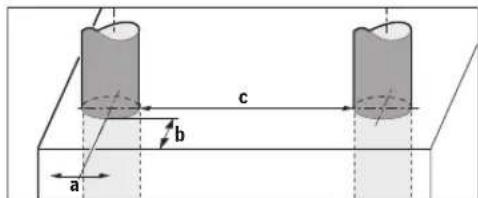
B) 03abHCHOCT OJ rONEMHHATA H BNDOT HA ObjKTOKAKOMATEPHJANOT H COCTOJBATA H NOINORATA
C) HactaHyBaat cAmO HeCnpoBODnHBr HeuNCTOTmH, HO NobpeMeHo ce OeKBya npHBpeMeHa CInpOBODnBOcT pPei3BnKaHa oJ KOHeHa3aJa.
Cepnckhot60j8Ha cneuHnKaunohata nloka cnky3a jacha HndHTnHnKaunha BaHOT Mepeyepd.
PezyntaToT Od MepeHbeto MoKe Da 6nDe nOnow Bo norneHa ToUHOCTa H perHcTpHpaBeto Ha dna6OuHHaTa DOKONky CBOJCTBaTA Ha NoDnOrata ce HENOBONH.
3a TcT Ha npHemHnKOT, KOJ ro npOBepyBa BnJaHHeTO Ha CnHAnOT 3a npeuKN Bp3 MepHnOT ypeN, CE KOpHCTN KpItePHyMOT HnBOTO Ha KaNaUHT, KOJtO e DeΦHHpaH Bo ETSI TS 103 361 (V1.1.1) nornabje 9.4.1 co dnaobounHa ha objekt od d = 60mm
3a TcnpaBe 3a eNktpomarHHTATA KOMnTH6HIOCT Ce KOPnCT CNEHNOT KpHTePHyM 3a KaNAuNTET: POn OpeHn OKoHOctn (Ha np. eNkTPOCTaTuKo npaHebe HIN H3NoxyBaBe Ha eNkTPomarHHTH NOINbMoKe Da c BeBnJae Bp3 pe3yIaTne OJ MepeBeTo, AKTyEInHtpe3yIaTn OJ MepeBeto MoKe Da c H3ry6at N MoKe Da e Notpe6Ho Da ce pceTnpa MePHnot anat Co OTcpanhyBaBe H NOBtropHO BMETHyBaBe Ha 6aTePnTE.
Mohtaxa
Ctabahe/Mehybahe Ha 6atepn
3a pa6oTa co MEPHnOTypeCe npenopayBa KOpIcTeHe Ha ankAnHO-ManraHcNk 6ateHH.
3a OTbopahe Ha KanaKOT oN pnerpaData 3a 6atepn (4) npntncheTe Ha MexaHn3MOT 3a 3aknyuBahe (5) BO npabeu Ha cTpekata H n3BaTe Ro kanaKOT oN pnerpaData 3a 6atepn. CtaBeTe r6atepnte OHN. AkymyNatopckite 6atepn Bnatpe. BHHMaBajTe Ha tOHOCTa Ha noNoBITE corIacHo npKa3OT Ha NOKJoneoT Ha pnerpaData Ha 6atepn.
Pnka303a6aepnjata(b)BOrnpHATA CTATycha HeHTaHa ekpaHOT (16) ja npKaKxyBa Coctoj6aTa Ha HAnONHeTOCT Ha 6aTePNITE OHN. AkymyNatOpCknte 6aTePN.
HanomeHa:BHMabajTe Ha 03hakata 3a 6atepujata uTo ce MeHyBa, 3a HABPemeHo Da rN 3aMeHIne 6atepuIne oH. akymyIatopckIne 6atepn.
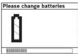
AkoHaekpaHot ce nojabyBa(16) npedynpybaheToo
NCKnyuBa.He MoKe Da ce N3BpM MepeHe.3aMeHete rN 6aTePnnte OAn.akymyIatopcKeTe 6aTePnN.
3aBaenehe Ha 6atepnte nptnchete Ha 3aHnOT KpaJ Ha
edHa 6atepnaJa/akymnatopcKa 6atepna, KaKo Ito e
npkaKaHO Ha cInKaTa Ha KaNakOT Ha npePadaT a3
6atepnn (1.).IpeDnnot KpaJ Ha 6atepniata/
akymnatopckata 6atepna ce ocnoodyBa od npepadaT
3a 6atepnn (2.), Taka ITO Taa MoKe NecHO da Ce I3BaIN.
CekoraawamEnybaTe rH CNTe 6atepnn OeDnHa. KopncTeTe
camo 6atepnn OeEN npOnBODnTe IN CO HCT KanaunTe.
Dokonky He CTo To KopHCTeMe MepHnOT ypeN NOBeKe Bpeme, H3BaTeTe r6BatePHTe OD Hero. DOKONKY ce IIOJOnTO Bpeme cKnaIpaHn, 6atePHTe Moke da KopoDnPaAT N da Ce nCnpa3HaT.
Ynotpe6a
3aHTTeTo MepHnOT ypeoBnA HnHpeKTHO HNOxyBaBe Ha coHcEBN 3pau.
He ro n3noxybajte MEPnOt ypeHa ekctpeMHN TEMnepaTyprn Hn TMnepaTyprn ocunnaHn. Pnir ROlemn TEMnpaTyprn ocunnaHn,ocTabeTe ro MEPnOt ypeHa hajnPBO da ceakHMath3Hpa, nped Da ro BKnyHTe. Pnri ekctpeMHN TEMnpaTyprn Hn TMnpaTyprn ocunnaHn, peneuHocTa Ha MEPnOt ypeHa pknKa30t Ha ekpahOT moke da ce hapyuaT.
Bo noneto ha ceh3opot (9) Ha 3aHaTa CTpaHa Ha mepHnOT ypeI He neTe HaneHHu Nnn 3HaUN. OcoBeHO 3HaHTe oM metan BnJaat BP3 MepHnTe pe3yntAtn.
KopncTeheTo Hn pa6oTaHa npedaBateH, KaKo Ha np.WLAN,UMTS,pap3a Bo3dyxOnIOBCTBO, TeneKOMyHnKaunckn KyHn HnMnKpOpaHOBn,Bo 6n3Ha, MoXe Da BnJae Ha cyHKuJaTa Ha MepeIbeto.
Mepnhtpe3yntaTH MoKeJa 6Hnat Hapyuene HnpaOn OpeDenH OkonHocTH uCNoB.N Obde cnaFaaT Ha np.6HmHa Ha ypeN, KOH co3daaat jaKn eNeKTPnHN, MaHTEH Nn ENEKTPOMaHRHeTH NONHbA, Bnara, rpaexHH MaTePmaJAnu To COpJXaT MeTaN, H0NaUcKN MaTePnaJAN KaUnpAHn Co anyMHnHymcKa fOnJa Kako H cnpoBoDnBn TanETn NnoOKn. 3aToa, npedynueBeTo, ceueHeTo nnn IroDaBeTo BO SIOBn, PAnfoHn Hn IOOBn, IpOBepeTe N dpyrHn hBOPn Ha HnΦopMaunn Ha np. rpaedxHn PnaHOBn).
ФункшонаннocT(BmDn CnkaB)

Co MEPHOT ypeI ce
npOBepyBa noDnOrata Ha
noDpaJeyoHa ceH3OpOT (9)
BO MEPHa HAcoka A do
PnKaxKaHATA MEPHa
dNabOChHa. MepeBeto e
MOxHO cAmO 3a BpEme Ha
DBHXeBeto Ha MEPHNOT ypei
BO npabeuB n npH
MNHMaJIHa MEPHa JHHJa oD
10 cm. NocToJano DbXkete
ro MEPHOT ypeI
npABONHHCKn Co Iecen
npTHCOK KOH SIOt, Taka
UTo TPKanata Ke Hmaat
6e36eHEN KOHTAKT CO sNDOT. Ce npeno3Haabaat ObjekTH, KOHtO ce pa3NkkyBaAT od MATEpHjANOT Ha sNDOT. Ha ekpanot Ce npKkaxyBa dna6oHHATA ha Objekt, DOKOLy eMOxHO, MATEpHjANOT Ha ObjektOT.
Ako MephaTaNHnJa H3NecyBa MNHmym 40cm MePHNO ypei neCHO ce DnKnIO eoNTo MeCto WTO Tpe6a da ce nCTpaKn, ToraawceIeHN KOH ONTMaHIN pe3yITaTH. CnryphOe cHaofaatyHKUHOHaHInTe rOpHN paBOHN Ha objektu, KOnlsto NOMHyBaat nonpeHNo Ha npabeoT Ha DBNXeBe Ha MePHNO ypeI.
3aToa cekoraaw nomnhybaje BkpcTeHO hAD noneto wTo Tpe6a da ce nctpaxn.
Ako ha e en h n ce haoraat nobekoe objekt, ha ekpaHOT Ke ce npkaKe oejkT0t, uja noBpwnHa e HajbIncky. IpTeCTaByBaHbeto Ha kapaKepnCTNKe Ta npohajdeHnte objekt Ha ekpaHOT (16) Moke Da ce pa3NIkyBa OD pKaTHuKte KapakTePnCTNHa ojektHe. Oco6Ho MHORY TeKHTE objekt Ce npTeCTaByBaat Ha ekpaHOT Kako NoDe6Ben. Iporonemte, UINHHdpnuHn Objekt (Ha np. PnaTCHH IN BODOBDHueBKN) Moke Ha ekpaHOT da HrIeDaAT NOTcHn, OTKONKy wTO HabCtHnCe.
3a6eJenBn ojeKTH
-Пл actuни ueBkn (Ha np. BODOBdHn PnactuHn ueBkn, KaKo nOHO n SuDHO rpeeHe nTH., CoДиJaMeTap OJ Hajmky 10 mm, npa3Hn ueBKn DjaMeTap OJ hajMaNky 20 mm)
-EnektpnHn cnpoBnHn(He3aBnCHO od Toa,daHn Ce noHnOHnn He)
- TpOpa3Hn cTpyJHn Ka6JIH (Ha np. do pepHaTa)
- CtpyjHn Ka6n Co man HanoH (Ha np. SboHO, TenefoH)
-MetalHHueBKN, npaKn, Hocauo od cekakOB BnD (Ha np. 电HK,6akap,anyMHNYM)
- ApMaTypa
-Дрвенгеди
-
Moxho e mepehe
-Bo6eTOH/apMnpaH 6eTOH
-Bo sHnH KOHCTpyKuHH (unrnn, np6eToH, rac-6eToH, nEm3a, BapOBHNK)
-BoJeCnHsIOBn
-ПОД NOВРИИКAKO rHnC, nIOUKN, TANETN, napKeT, TEINX
-3aDpBO,rncKapToH
Ioc6HH MePHn cnuyan
HEnOBONHTe yCNOB MoKe cyuTHNCKn Da BnJaT Bp3 MEPHNOT pe3yNTaT:
-NoBekeCnojHn SdHn KOHcTpkyuHn
-Ⅰpa3HH pnaactnHn ceBKn ndpBeHN rpeHN BO Wynnn HneCHN SNOBn
-06jekTN, KOHJTO CE KOCO NOCTaBeHN BO SHIDOT
-BnackhenMaTepnjanHaSNDOT
-MetaHINIOBpuHHN
- Lwynnnn BO snd; Tne moke da ce npkaat kaoko objekt
-5n3y do ypei, konIto npOn3BeyBaat cnHIMaHTHN mEneKTPomarHTHN nONHbA, Ha np.6a3HnCTAHmHa MObHNN ONepaTOpn HreHepaTopn
CtBaBbe Bo ynOtpe6a
BknyBaBe/ncKnyyBaBe
PepBknyBaBeHaMepHnOType, npOBepTe nIeTo Ha cEn3Opot (9) da He e BnaXHo. DOKoKny e BnaXHo, IcyuTe Ro MepHnOType Co Kpna.
ДOKONКМЕРНOTурб6нн3нoxKeHHa rolemn TemnepatypnHa pa3nKN,octaBeTe ro da ce npnaorOHa Temnepatypata npedda Ro BKnyHTe.
BknyBahe
-3a BknyyBaBe Ha MePHNOT ypeI npHTNCHe Ha KOnyTe 3a BknyyBaBe/HckNyYBaBe (15) HnHa KOnyTe 3a CTapT (11).
-LED-CBETNkata(17)CBETEN3eNEHOce nojAByBaCTAPTHNOTEKPAH3a4sHaekpahOT(16)
-Ako co MEPHNOt ypeH He BpHnTe MepHe H He npHTNcKaTe HeKoe KOne, Toj ABToMaTcKN Ce NCKnyyBa NoCne 5 MNHyTN. Bo MeHnTO NocTaBKn MoKTe Da ro npOMeHnTe OBA
NcknyyBaHbe
-3a NcknyyBaBe Ha MEPnO t ype n pntnche Ha KOJIeTO 3a BknyyBaBe-NcknyyBaBe (15).
-ПинСКЛУЧВАБЕHAМЕРНNotypedOctaHyBaAT COДРЖAHN CHTE N3бранNIOCTABKN BO MEHJaTa.
BknyBaBe/HcknyBaBeHa CnHannnTOn
CoKoJIyTeO3ByuHcRHaI(13)MOxTe Da rBO KJlyUHTe HnN NCKJyUHTe 3ByuHnOT CnHAn.Bo MeHToIOCTaBKn MOxTe BO NOdMeHtO
Ppoec Ha Mepehe
BknyeTe ro MEPHnOypeJ. Ha ekpanOT (16) ce nojabyBa CtanhapdEn ekpan 3a npKakyBaHe.
184 MaKeDoHcKn
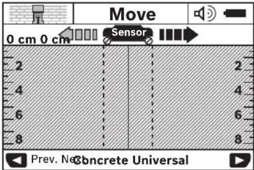
Noctabete ro MEPHNOrypeHa sHn dNBHXeTe ro Bo npabeu Ha dBHXeBe (BnD,ФyHKUHOHaHOCr (BnD CNka B), CtpaHnca 183) no shoT. MepHnte pe3yntatn ce npkKaKyBaAT no MNHMnHaHa MEPa NnHJa od 10 cm Ha ekpaHOT (16).3a da ce do6njar TouHm MEPn pe3yntatn, DNBHXeTe ro MEPHNOrypeIeIOcHo n IoneKa Hn npETnoCTabEHNOrObjectKBO SHoT.
Ako 3a BpeMe Ha MepeBeTo MePHNOTypeI NOINHByBaTe OD SNIO TNI Hr O Ro KOpNCHTe 3a NOBEKe O2 MNHyTH (DNHXKeHe, PnTHNcKaHe Ha KOuHbHa), Ha eKpaHOT OCTaHyBa nocneHNOT peyntaO MepeBeTo. Ha npka3oT ha noPaJyTe HA cEH3OPOT (c) ce nojAByBa nopakata
AkoLED-cBETNIKATA(17)CBETNUPBEHO,ToraWBO noneto HAceH30POTCEHaORAobjKT.AKOLED-CBETNIKATA(17) CBETNEHEO,ToraWHEMAobjKTBONONETOHAceH30POT. AkoLED-CBETNIKATA(17)TPENKAUPBEHO,ToraWBO noneto HAceH30POTCEHaORAobjKTnoHaHO
PpeJa dynuHTe BO sH,ceyete HnHrOaTe,tp6a Da ce 3aHTHTe OJ ONaCHOCTn CO NOMoH Ha Dpyn H3BOPHa HnHΦopMaun. Bndejkn Ha MepHtene pe3yTaNMOKe Ja BnJaAT OKoJIHNTe BnJaHnJa HncoCTaBOT Ha SNDOT,MOxHa e ONaCHOCT,naKo npKa3OT He nokkyaBa ojeKT BO nolTe Ha CEH3OpOT (LED-CBETNkata (17)CBETn 3eNoHO).
Elenentn3a npka3 (BNDn CnkaA)
Ako noC ceH3OpOT ce haof a ojeKT, ce nojabyBa BO
noDpaJyToHa ceH3OpOT (c) Ha npKka3OT. Bo 3aBnCHocT OD
rOleMHATA nIa6oHHATA Ha ojeKTOT MOXHO e
npeno3HaBaBe Ha MaTePnJAt. INa6oHHATA Ha
oJEKTOT (1) Do rOpHnOt paHa npohajDeHnOt ojeKT ce
pNkKaKyBa BO CTATyChata NHHJa.
HanomeHa: Pnka3OT Ha dna6ouHHata Ha dyuHbe (I) kako H KapaKeTpncHTKHe Ha MaTePnJaT0 (m) ce OJHeCyBaat Ha objektot PnkaKaH co CpHO BO cEH3OpOT.
Pnka30 3a MaTepuJanoT Ha Objekt (m) MoKe Da rH HMa CneHnTE CBOJCTBa:
MaHHeTn3HpAHH,Ha np.apMnpaHO Xene30
HemarHeTn3npaHn, Ho MetaHn, Ha np. 6akapn HcBKN
HemetaeH,Ha np.DpBO HnN nactka
KapakTePncTHKnITeHaMaTePnJanoTceHeno3HaTH
Pnka303aeneKtpnHnKaBnNoHaHOH(n)MOKe Da HmAcneHNHe CBOJCTBa:
-NonHANOH
HanomeHa:Kaj objekTn Iod HanoH He ce PnIkaKaYBaat OctaHaTH KapaKTepNCTKN.
HejacHO,dannCe nOHaONnHnHe
HanomeHa: EBeHTaHnT PtoFa3HnTe CtpyJn Ka6n He ce npeNo3HaBaat KAcO eNeKTPmHn Ka6n NoI HAnOH.
OndpeyBaBetoHaKapakTePncTHKaTaNODHANOHOMOKeJa 6nDE MHOry OrpAHueHo npu BnCOKa penaTNbHb BnaXHOCT HA BO3DyXOT (>50%)
Iokann3npaheHa o6jeKTHTe
3a da ce nokanmnpaat ObjekTHe,doBONHO eHOKpaTHO NOBKeYBaHe Ha MePnata HnHja.
Ako He hajdeh objekt, nobTopete ro DnHexeBoTo nonpeHHO npTeXoDHOT Mepe npabeu (BnH,ФyHKUHOHaHooCT(BnD cnka B), CtpaHua 183).
Ako cakaTe TouNo da ro nokaiin3npate ngobeneKeite npohajdeHnot objekt, DBnKete ro mepHnot ypeJ ha3aI no MEPHata nnHna.
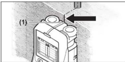
Ako ce nojabn objekt kako ha npimepoT noCpeHaTa nnHna (k) Ha ekpaHOT (16), toraaw moKTe da HappaBHT rpybo Mapkpapahe ha rohpHOT oBeJeKyBaU (1). Cenak Oba oBeJeKyBaHBe e touHo cAmO toraW, kora ce paBoTu 3a objektTo koJ e ToUHO BePTKanHO NoCTaBeH, bNejeKnNoIeTo HA cEH3OpOT ce Haofa HeHTo noD rohpHOT oBeJeKyBaU.
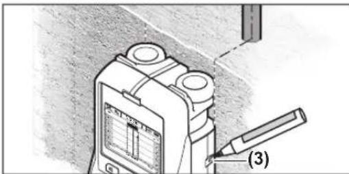
3aTOHObENeKyBaBeHaOBjekTOTHaSHOTDBNKeTe rO MEPnHOT ypeKo KON HeBO NIN DeCHO,IOeKa IPOHajDeHnOT oBJKT He ce HajiNe IOd HADBopeuHNOT pa6.Ako Ha ekpaHOT (16) ce npkKaKe IPOHajDeHnOT oBJKT Ha npHMep BO CpeHHATA NOI O3HaueHATA DecHa NInHja (g), TOraw MOKeTe Ha DECHNOT ObENeKyBaTuHO da Ro OBENeXHTe (3).
Moxete da ro yTbpnte npocecot Ha npohajdennot objekt, co Toa wTO HAn3MeHnHcKe NOBHeTe NOBeKe MEPHN
Hn Hn EHa No pyra (BnDn CnkaI) (BnuN,PiHmepn 3a MePHn pe3yntaTn", CtpaHnca 187).O6eJekete n I NOBP3ETe r COoDBETHne MePHn TOCKN.
Co npntnckaBe Ha konyeto 3a cTapt (11) Moxete Bo ceke BpeMe da rH 36pnWte npohajdeHnte ojeKTn Da CTapTyBaTe HOBO MpeHe.
PpomeHa hapexHmHa pa60Ta
CoKoNCHbTa3aH36Op(10)H(12)MOKeTeJaMeHyBaTe Ha paJIuHnpeKmHa paBoTa (Moyn).
-Пинсichte ro kpaTko KOnyeto 3a n36bp (10),3a da ro n36pepe cneHnOT peKHM Ha pa6ota.
-ПинсHTeRo KpaTko KOnyTe 3a H36Op (12),3a Da ro H36peTe PpTeXOuHnOT peKmHa paBota.
Co n360pOT Ha pexkHmTe Ha pa6oTa MoKTe Da ro npnnaOgnte MePHNt ype3a pa3HN MaTepnjAln Ha sIOBn. Ondocnata NoctabKa MoKe da Ce BnDn Bo ckeoe BpeMe BO nOpaJyeto Ha npKka3OT (h) Ha ekpaHOT.
(YHnBep3aen 6eToH) (npetxodno noctabeh)
PexmOT ha pa6ota
(Bnaxhen 6etOH)
PexnmoHa pa6oTa
BHHMabajte Ha Toa, DaKa Ha 6eToHOT My ce Notpe6HN NOBeKe Meceu 3a cIIOCHO da Ce HcyuN.
(CneunjaneH 6etOH)
PexnmoHa pa6oTa
Ako ce npinkakyybaat nobekoe objektu, moke da 3naHn deka ondte npiektho donx apmatypata. Bo oboj cnuyaj npemecteTe ro mepHnot ypeD 3a HeKONky caHTIMetpn n npobajte ONDBO.
(3arpeBaHbHe naOBpuHHa)
PekmOT ha pa6ota
(Cyba rpaδa)
PexmoHa pa0ba (Cyba rpa6a) e HameHc 3a npohaoarhe Ha dpBeHHrpeH,MetaHn WnKn H eneKtpuHn CnpoBODnHs 3a cyBa rpa6b (dpBO, nnc nTH.) PnonHeTn pactnHn UeBKn HpBeHHrpeH ce npkaKyBaat ndentHNO. PpaHn pactnHn UeBKn He ce npkaKyBaat. MaksmaHata dna6oHHa Ma MepeHbe n3HeCyBa 8 cm.
(Metan)
PexmOT ha paOta(Metan)eHaMeHET3a
IOuipaHe Ha MetAnHObjTeN KAbn NOD HAnOH,DOKONky
Dpyrnte pexmm Ha paOta BO pa3nHn ycNoBn Ha SuOBn
He daBaat 3aOBoJNTeHN pe3yntaTn. Bo OBne cnyan
pe3yIATnTE 3a npEno3HaBaHBe BO OBOJ pexm Ha paOta ce
NOBcOKH,HO NOMAnky PpeU3HN.
IocanHOCTaMOKe MHORYaCe HAMnnprRONema penatNBbBnaXHcTHaBO3dyxOT(>50%)
(Передна сгнанн)
PexnMOT ha paBota
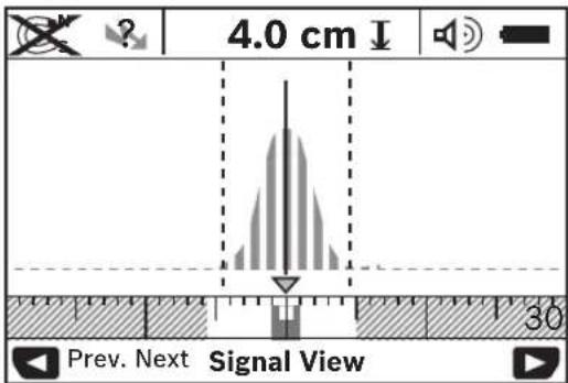
BpBOT Ha KpHbata Ce npKaKyBa BO Man pa3Mep HAD npKa3OT Ha pexHMOT Ha paboTA (h) BO U-ΦoPMa. Ce npKaKyBaAT dna6ouHHATA Ha Objektot NdoKoKy e MoXHO n CBOjCTbata Ha MaTepnJaIOT. MakcmanHa Tda6OuHnHa MepeHe 3NecyBa 15 cm.
Длабочинаха obektot He moke da ce 3aknyn cnopej jaunHata ha cHraHnot.
PpomeHa HbIDOBHTe Ha npka3
Hanomeha: Moxha e npomeha Ha BnOBeHe Ha npka3 Bo CHTe peKIMHa pa6ota.
IpxeTe rno npntncatn konuHbata 3a n36op (10) Hnn (12), 3a npcepnyBaBe oC tAndapHnOT eKpaH Ha npKaKyBaBe BO pexHMOT CO MetapCKo MepeHe.
186|MaKeDoHcKn
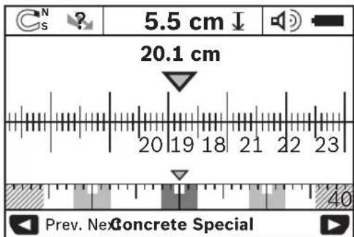
PeknMOT Ha Metap Ha npnMepot Ja npnkaxyba nctata CHTyaunjka kako Ha cnkata D: TPNKeene3n npauchnHa ncto pactojahne.Bo pexnMOT Ha metap moke da ce odpein pactojahneto mety cpeHNHe Ha npohajdeHte ojeKtn. Pnd npkazot 3a dnaobounhata Ha objekt (I) ce npkaxyba pactojahneto onpateho od noeHTa TOka,Ha npnMep 20.1 cm.
Bo manata Mepha npaqua npeky npka30 3a pekim Ha pa6ota (h) Tpnte npohajdeHn ojeKtN ce npKaKyBaat KaKO npaboarHnHn.
HanomeHa: Pnka3OT Ha 03BOHeHATA nla6OuHbHa HaIyueHe (I) KaKo HkapAtePcHKeHTe Ha MaTepJAnOT (m) ce OndecyBaat Ha ojeKTOT npKaKaH co UPHo BO CEH3OpOT. 3a Da BpaTHe BO cTahdApDcH ekpan 3a npKaKaYBaHe, KpATKO pNtNCHEtHa KOnyeto 3a N36Op (10) HIN (12).
Hanomena: Ce MeHyBa caMo npKa3oT, a He MEPHnOT peKIM!
MeHnIOCTaBKn
3a da ro OTBOPHTe MeHTo IocTABKN, npNTNCHe Ha KOnHTo 3a noDecyBaBe (14).
3a da ro hanyuHTHe MeHHTo, pNTHCHETe Ha KOnHTO 3a CTAPT (11). Ce npe3emaat NoCTaBKNTe N36paHH Do OBOJ MOMENT. Ce aKTHBnPa cTaHdapHNOT ekpaH 3a PnKkaxyBaBe 3a MEPHNOT IpOuec.
HabnnpaBe BO MeHHTo
PnHTCHETe Ha KonHcTe 3a noDecyBaHe (14), 3a da nIzrata HADONY.
PnHTNCHeHa KOnHbTa3a H36Op (10) H (12), 3a Da Hn36epTe BpeHocHTte:
-
Co konueto 3a n36op (10) ja n36hpate Dechata OHN. cnEHaTa BpeHocT.
-
Co konjteo 3a n36op (12) ja n36npate nebata oH. npTeXOHNATA BpeHOCT.
(Ja3nk)
Bo MeHTo
(BpeMe Ha ncknyyBahe)
Bo MeHnTo
ce npabaT MepeHa Hn NOCTaBKn. FabpnuKne nocTaBeHO <5 min> (5 min).
(Ocbetnehoct Ha ekpahot)
Bo MeHHTo
(Ocbetnehoct)
Bo MeHHTo
(3bvyHH cnrhaH)
Bo MeHnTo
-Фаврик e noctabeho
-Пи NOCTaBkata
-Пи noctabkata(Keyclick)(KlnKHyBaBeHa KONHbata)ceДаBa3BvyeHcHnIcMaO npn eHOn pHTNCKaBe Ha KONue.
(CTaHdApEnpeXHM)
Bo MeHHTo
MeHH DononHHTeHN NoCTABKN
3a da ro OTbOpHTe MeHTo IOnOJIHHTENH NOCTABKN, npTHCHETe, cAmO kaj NCKnyeH MEpe HyeD, hCTOBpEmHO Ha KONUeTO 3a NoDecyBaHe (14) n KOnUeTO 3a BKNyUyBaHeNCKNyUyBaBe (15).
3a da ro hanyuHTHe MeHnTo, pInTHcHTe Ha KOnyeto 3a CTapT (11). Ce akTHBnpa CTAHdApDnHOT EKpaH 3a npKaKaByBaIbe 3a MEPnHOT nPouec H ce npeSemaat NOCTaBKHTe.
HabnnpaBe BO MeHHTo
PnHTCHETe Ha KonUeTo 3a NoDecyBaHe (14), 3a Da IIN3rAte HADONY.
PnHTNCHEtHa KONUHbTa 3a H36op (10) n (12), 3a Da n H36epTe BpeHocHTte:
Co konyeto 3a n36op (10) ja n3bnpate Decnata oH. cnednata BpeHocT.
CoKoJnueTo 3a H36Op (12) jaH36npaTe neBaTa OHN. npTeXOHaTbpeHocT.
(MnΦopmaun 3a ypeod)
Bo MeHTo
Bo MeHTo
PpHmepn 3a Mepn pe3yntaTH
HanomeHa:Bo cIeHnIte npImepnHa MePnHTypee e Bknyeh 3ByHnOT CnHnJ.
Bo 3aBnCHOCT OJ TOnEMHATA HnaBocHHATA Ha ojekTHTe, KOHTo CE HAoAaT NOI nonTo HA ceH3OpOT, He cekoraw MOKe CO ciYrpyHOCT Da CE yTBpH DAHI OBOj ojekTe nOHO.Bo OBOJ Cnyaj Ce nojAByBa O3HaKaTa Ha npka30 (n).
EeKeTpHcH Ka6en noH HANOH (BnH cHnKa C)
Bo noleto Ha ceh30pot Ce haofa metaleH ojeKT noHaon, Ha np. eneKtpuueH Kaben. InaobouHHata Ha ojoektot n3heCyBa 1,5 cm.MepnhotypeNcnpaKa npedynpyBuayKn CnHah3a cnpoBOHNiNoD HAnOH BeNaH wTOM ceH30pot Ke npeno3Hae eJeKtpuueH Kaben.
Kene3Ha npauka (BnH cnka D)
Bo nppaueTo Ha ceH3OpOT ce Haora MaHnTeH ObjeKT,Ha np.Keene3Ha npaayka.Bo Herobata IeBa H n Deca cTpaHa CE
HaofaatpyrHnOjektnHaDbOp oN noDpaujeto Ha ceh30pot. IanaobounHata Hoa jektot n3hecyBa 5,5 cm.MepHnotypeed nCnpaka 3ByeH cnHnI.
BakaphauebKa(BnHcnkaE)
Bo nopajueto Ha cen3opot ce haora metaneh objekt,Ha np. 6akaphauebka.Dnaobouhata Ha objektot n3hecyba4cm. MepHnOT ypei Hcnpaka 3Byueh cnHan.
TnactuHnn dpBHeo6jeKT (BnDn CnHaF)
Bo noneto ha ceH30pot ce haora hemetaneh objekt. Ce pa6oTH 3a nactuhen npn dpBEN objekt bNcKy do nobpwnHata. MepHnotypeHncpaKa 3ByeH cnHan.
Umpoka noBpuHnHa (BmH cnHka G)
Bo nopajeTo Ha ceH3OpOT ce HAOHa METAnHa, npoWnpeHa NOBpUHa, Ha np. MetaHa nOua. Dna6OuHaTa Ha ObjekTOn H3HeCyBa 2 cm. MepHnot ypeNcnpaKa3ByeH CNrHan.
Mhory hejacn cnHann (BnH cnnKn H-1)
Ako BO cTaHapHnOT ekpaH Na pNkKaJyBaHe ce nokKaYBaat PpemHory objekt, BepoJaTHO BO SIOt NOctojat MHORY wUynHH. Cmehete BO peKIMOT ha pa6ota
DeΦeKT - PnHnnn nnomou
| Грешик Пришина Помош | ||
| Мернот уreed не моче на ce вklуч. | Празни батерни Менивање на бateрниte | |
| Вмет国安се се батерни co和完善сян поюяпа на бateрниte | ||
| Мернот уreed вklучен и-he pearupa. | Istваде тиSBateрнип и nobсторноставete ng | |
| Мернот уreed вklучен noюл паден | Почекajte,doeska he ce nocturnal dozbolentata Tempepaурна ралпца | |
| Прида на ekpanот: <Slipping Wheel> (Лизрачко Трkanо) | Трkanotro go ryби kohtakot co smdт. | Причеснete go konqueto zaстар (11) и рprдвженье на Мернот уreed вимаовке на контакт о co smdot co дveite doлин Трkanla; kaj helamn sinobni poctabete TeHOK Kapton Mefy Дveite Tpkana n smdot |
| Прида на ekpanот: <Speeding> (3a6рзваьe) | Мернот уreed се двожи co nperefolma sbpэиha | Причеснete go konqueto zaстар (11) undвожete ro Мернот уreed поlexа no smdot |
| <Temperature over range> (Temnepatypata e надMinнatable) | Почекajte,doeska he ce nocturnal dozbolentata Tempepaурна ралпца | |
| <Temperature under range> (Temnepatypata ne e доctrngнatable) | Почекajte,doeska he ce nocturnal dozbolentata Tempepaурна ралпца | |
188 | Srpski
Tpeoka PnpuHnI pomoi
cnHe npHaNo cnHnA
(ДeTeKтнан e
MepHnOT ypeI abTOMaTcN ce HcknyuBa. Dokonkye BO3MOKHO,OTcPaHete rnpaHOBpaHOBITE KOuTo rnpedn3BKnkyBaAT npeKHTe,Ha np.WLANUMTS,padap 3a Bo3dyXoONIOCTBO,TeneKOMyHKaUNCKN Kynn HmN MKNpObpaHOH NOBTOPO Bknyute Ro mepHnOTypeI
OdpKyBaBe H cepBnC
OdpxByabe n qHCTebe
PpOBepeTe ro MePhHnTopey nped cekoja ynoTpe6a.
PnBnINNBOWTeYBaHaNnOaBaBENdNOBN BO BnATpeHIOCTA H MePNHOyE,6e36eHnTO ΦHKUHOHPaHe He e NOBeKe 3arapaHTpaHO.
OndjyajeHCTOTataHaMepHnOType,3aDaMOKe 106po H6e36eHNO da pa6oTne.
He ro notonybajTe MepHnOT ypeD BO BOnn npynteuchn.
I36pHwTe rH HeuHCTOTnHTe co cyBa, MeKa KpNa. He KopHCTe TcpeCTBa 3a uHCTHe Hn pactBOpN.

BHHMaBajTe Ha Toa, cepBnCHHOT nokloneu7 cekoraaw da e do6po 3aTbOpeH. CepBnCHHOT nokloneuCme da ce OTbOpHc mo O od ObnaCTeHa cepBnCHA cnYkBa 3a Bosch-eneKtpnHn anatn.
MepHHOT ypeD cKlaIpaJte ro I TpaHCnOpTpJaTe ro caMO BO HcnpaHaHaTa 3aHTNTHa YaHTA.
Bo cnuyaj da Tpe6a da ce nonpaBn, npateTe ro mepHnotypeB Do 3aunTHata yHaT.
CepBncha cnjx6a n COBET npn KOpNCTehe
CepBnCHa cny6ka Ke OJROBOp Ha BaWHTe npaaBa BO BpCKa co nonpaBkata NOpjyBaHeTo Ha BaWHTnpo3BOKaKo Hpe3epBNHte DeIOBN. O3HAKN 3a EKcIINO3Ja HnΦopMaun 3a pe3epBNHte DeIOBN HCTO Taka Ke HajTeHa: www.bosch-pt.com
TMMOTa coBetyBaIbe npn KOpHcTeHe Ha Bosch Ke BN NOMORHe DOKOKy HMaTe npaHaBa 3a HaWHTe PpO3BOOnnOPema.
3a cnte npaaaba n hapaunn ha peaebpnn denobn,Be monme habeTe ro 10-umpehenot 6poj od cneuqkaauhoata nouka h npon3bodot.
MaKeDoHnja
Д.Д.Енектпс
CabaKobayek47H,6poj3
1000 Ckonje
E-nowta: dimce.dimcev@servis-bosch.mk
HHTEPHEt: www.servis-bosch.mk
Ten./pa:Kc:02/2467610
Mo6.:070595888
Д.П.T.Y "POJKA"
JAnI NyKpOBcKn 66;T.U ABTOKOMaHaJaNOKaI 69
1000 Ckonje
E-nouta: servisrojka@yahoo.com
Ten: +389 2 3174-303
Mo6: +389 70 388-520, -530
OtcpaHyBahe
MepHnTe ypeHn, akymnataopckne 6aTeepn/H6aTePnHTe, onpemata n ambaJaxnTe Tpe6a da ce oTcpaHat Ha ekOLOWNI pnpfaTINB HauHH.

He nФрпajte Мернite урdenи 6aTepeHnTE BO DOMauHnATA KaHTa 3a OTnadoOn!
Cama 3a 3emjnte oEY:
CnopeE EBpONckata DnpeKTHBa 2012/19/EU MepHne ypeiTo ce BOH ynotpe6a n deFeKTHte HnN NcKOpHeTHe 6aTePNn CnopeDnpeKTHBaTa 2006/66/EC Mopa OndenHO da ce co6epa n da ce peuKnnpaat 3a NOBtPha ynoTpe6a.
Srpski
aagagbll jno wlaal oacayp 4 .6wlaIuauW
auiIul
| 3601 K10 008 | ### |
| ±5 po | ### |
| ±10 po | ### |
| 40 po | ### |
| p°50+...p°10- | ### |
| p°70+...p°20- | ### |
| ### | |
| jüssen 5500-2200 | ### |
| blg lgl 0,01 | ### |
| ### | |
| jüssen 6.1-5.9 | ### |
| gk jürgen S. Jürgen 72 jürgen S. Jürgen | ### |
| p 2000 | ### |
| % 90 | ### |
| (C)2 | ### |
| (AA) LR6 lgl 1.5 × 4 | ### |
| (AA) HR6 lgl 1.2 × 4 | ### |
| ### | |
| aclu | (###) ### |
| aclu | ### |
| ρ≤0.65 | ### |
| ρ≥0.65 | ### |
| ρ≥0.65 | ### |
| ρ≥0.65 | ### |
aawwllg jssj0s yds wlll jol ealaw
jll jll jll jll jll jll -
a.bj1s0
auiuoggaw
(n) 1g s s s s bgs g sbgs a lal alal alal alal alal alal alal alal alal alal alal alal alal alal alal alal alal alal alal alal alal alal
1000000000000000000000000000000000000000000000000000000000000000000000000000
joljoloo
J So Jn Jn Jn Jn Jn Jn Jn Jn Jn Jn Jn Jn Jn Jn Jn Jn Jn Jn Jn Jn Jn Jn Jn Jn Jn Jn Jn Jn Jn Jn Jn Jn Jn Jn Jn Jn Jn Jn Jn Jn Jn Jn Jn Jn Jn Jn Jn Jn Jn Jn J n Jn Jn Jn Jn Jn Jn Jn Jn Jn Jn Jn Jn Jn Jn Jn Jn Jn Jn Jn Jn Jn Jn Jn Jn Jn Jn Jn Jn Jn Jn
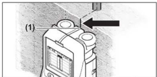
la Jaii aaiia I g jaoa 11g
gao gao los.16) awu w (k) aoii
Luo ic axaw jao doe gao elkso, liall
doal oogj uuslg.(1) glll jauill
gac kuiu uoi jai
- -s#ulogjglwqalI
g j 15 uL bc baiy p9 g wiaa lac 15 qj
1u uuiu uu uu>Cut-off time(Lab) Cg)<,Jai)>Cu (Lab) Cg) aaoJI,239. Lab - Jauill JJ Lc baiy U
Lab
lab sic lgaos oJluu ssaal bai kao -
aagaijLwI Labg
jLJUgI gI JI JI JI JI JI JI JI JI JI JI JI JI JI JI JI JI JI JI JI JI JI JI JI JI JI JI JI JI JI JI JI JI JI JI JI JI JI JI JI JI JI JI JI JI JI JI JI JI JI JI
wlaa a
aWwI 0gJb. wai I 6c Jswy p (16) aWuU y gail
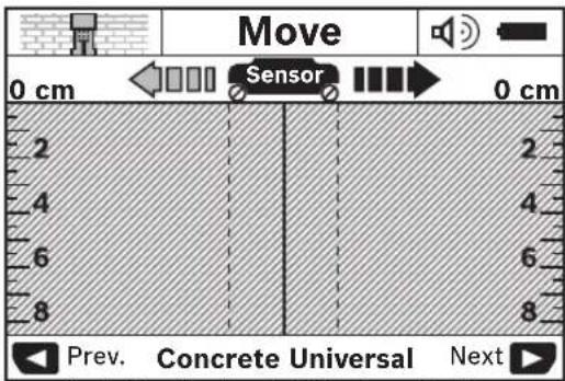
JWl oJI g Lsag bll Jc wll 0sc 236 aall, "(B ojgall jail) Jall aab, jail) agw s y wll g iu jy p u Jd lgl 0sc J (16)awll gpw 10 wu q Jolksu wll Jg gai I y gai I y wll .aayw gai I y uagau Jn J. 2g J u wll I y gai I y wll aui Jy uu Jg Wgai I y uagau Jy uu Jy wll (jgI y gl bc wll, kssu) JgJg Jull (c) juuuall Joo nn Jy uu Jy uu Jy uu Jy uu Jy uu Jy uu Jy uu Jy uu Jy uu Jy uu Jy uu Jy uu Jy uu Jy uu Jy uu Jy uu Jy uu Jy uu Jy uu Jy uu Jy uu Jy uu Jy uu Jy uu Jy uu Jy uuu U (17) uuu U (17) uuu U (17) uuu U (17) uuu U (17) uuu U (17)
Jn Jn Jn Jn Jn Jn Jn Jn Jn Jn Jn Jn Jn Jn Jn Jn Jn Jn Jn Jn Jn Jn Jn Jn Jn Jn Jn Jn Jn Jn Jn Jn Jn Jn Jn Jn Jn Jn Jn Jn Jn Jn Jn Jn Jn Jn Jn Jn Jn Jn Jn
(duauiwj
aiwj)
aaoaJUcUuUoUuU (aa
SsOeP aUauauai uUauu Ugogall
Igbluaguiuaguiuuguul
uw15uuaqocuolduuuj
Jauoll qoJQJn oossc ope j
duJluooLcUuall oocuuuogai
alalooJG uauull oocdajguuill
(5J0JUgagluyiai
(panl heating>
(8bawai aio)
(aJJJJJ)
(aolcaiwj)
(duuw)
aiwj)
J 10
239
(duu)
aJIu ciSao (aJI)
m = 311
C
te
spee
C
一
H
C
aJU JuaJI 10uJU Lc g
jjaw|gaaawllg|Sawwlaaasj
172 × 25
(Dogall jail)
a:100 jnunll lJy uynblio 0jz d 5j 100j oJUu Uc ag aoy Lc 9o 15 40 5,5 oJol Igac gI y. Jnnnall Joo aJia .agoo Jw! wal
(Egjgl)wlaalnog 10000000000000000000000000000000000000000000000000000000000
aiiall usall jllal pala awwgo
Sall aabio. jwll ojiu yjbn jnlaa
aJySll oSsI Jou
ylll/psjllg wlll sdc no jalll l gnnnabla aagbclgglgogayosullaalolg alall jslall lgaow yipnne aill
a/psal/ajg 1jai jai

20300 1
:gjkiJ sav.outillage@ma.bosch
la
p.p.μgglaljailil
gdsu 131
159j 112 Jlae abluw
:+96899886794
:gJU malatanpowertools@mal
j6
p.o. liJgJgJJ
gdsu uug51.
aaa+974 40065458
:U5+974 4453 8585
:gjskJyjcsd@icsdoha.com
aJgawll aJall aSlooll
(gSuaaillseallgag
gI gI aabio,aiwJl 14gSJI
21431
1528c+96626672222:
:U5g+96626676308
roland@eajb.com.sa:gjgjSJ
UJgW
auiu gulw
1030 ggsuμgss
U
+963212116083:
rita.dallal@ hotmail.com:gjgjj
U
p.0.3.μwμgiμgμg
UgagJwZ.l.abgbjIaaj7
yolj jyao
2014wgej
+21671427496/879:
+21671428621:UuS
sav.outillage@tn.bosch.com: 已 _ 1 ^ 已 gjSJ s
dJdJIyJUJlJxJ
g gio.o.1 1000Jg UJUuUaJxJoll
1984 1g
aai 0oio -oagglg
aJwI
:+97165932777
+971 6 533 2269:Uu≤Lg
powertools@centralmotors.ae:gjSJ
aJlJIJIJIgJawwgo
dai jaljll qo paoi. gui jgulw
+967-1-202010:
:Uu+967-1-279029
tech-tools@abualrejal.com:gjgjj
oljwJjal
oLuo yu jds oBsws |jal sLoJaw
ds wU Gy jol jjg u bjo, g uu
.owl Oxol lai Jd j J
S>0g20j1c1o2w a9p>:sJws
(1)JisioLcSosUcwI Jawg bK
> (1)
> ≥slant 山 (m)
()
wJl
iai! 1jgsw
jg jglgjI J L glaiml S daom
S oJil jIj dS jgog Jd.
gwi jy jj Ojgiw
sggo jblao jqn CwI Jkso
I JlaioiJ .siu wJj

yjggi
aia 1
JlJlwgglg 1
gcbbljclwolsso0jdlgs
Jusw s w d o sii c ju Jy j 1s y ETSI Jd s g w o laaw jgi g j 20
gac y 9.4.1 w TS 103 361 (V1.1.1
cwl o w juiu 60=d
jUg jSj jJUoO UjUu 0uoi
L Sjilui L jsi Jy dai sijlo) ola bjuw ly
L W CwI Jsao (uublioo slqil sdo y
Sjol jil g uoi jg jg w cyo ojl si
Soo CJiwl jlg g sigw Scl w osoo
Ljul ojgl jgl g jg jg l Ss oJl jj
uai
j/
1sgljI 0slai sJg oJl jI JSL Sg
.og Ggj SjIu L gjjio-llSjI
SdoS (4) SjU S daaoo wag Jus Jg
g SjIu Gg JIg J (5) Osiis Jg
Jg I I SjU .SjU J SjU S daaoo wag
aao JI Jg d, Lg SjU Slae I pSia
Jal Jdgg Gg Gg SjU Slae
aagj sljla
(16)gaaa aai bai jb (b) (jui jai lai
1sjjw syl y golg slj jlw c
.
sjiu sisi agi jagai jgo sijui slai a:dis iis oge gao ayj sjjw yol
julai daa jda liq
Please>Jw (16) <change batteries
jogcI L (sjiy la)
paoaogwosu (204 sigwgoaaiaai
a jg jj jj g
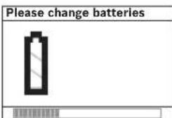
yJ 1sOla sSjS SjS oJl si Cua J. .gW jgsjL sJw L cal g slu .sw L qai
Jos 0s w os1s Jocai paa (9) aonig Jols
C
(gj jol jol jol jol jj
da 59j SjS oJ ai dai jai sii jg Js Ogdo Jsi lai j. sio gul
jla liu. gw o o s (Lg)
jU CJSa dU JglgJlgSgJogJgJg
JUJUeLoI (11) JUJUWdssLdoS
gug Lg E9j gjj 5u ojl
j0g(17)(5)(1)()()
jwg jggo s. CwJ Ssa oSg oo j j
j()
sui jaiu jgooj .uuu oogoo
jSLSjjgLSSLSOJSLsALgWjl
Jus 10g J J L Jw Jw laj
Gggo goo liu w g) d o jlu
.(gugj juwaj (17)ssl g
(Aj gai duiis egaj) jgi daa o j slaoi
gaw o01 jluw wai (c) jwa gaa
y
uU (1) 5jSgW goc. CwU SsO oos
013 uww Cuaog bbs osw Gw
.
g g (1) gaw gac jw loj po :aiSj
0s1 sai o w wai lai do bjo (m)
wJoo
aI 1 aJgJgJgJgJgJgJgJgJgJgJgJgJgJgJgJgJgJgJgJgJgJgJgJgJgJgJgJgJgJgJgJgJgJgJgJgJgJgJgJgJgJgJgJgJgJgJgJgJgJgJ
:
yio yuolisi 0
aolgljolgblzlo
SauuUg sio sj
glo gai liu j
100000000000000000000000000000000000000000000
:duwduwls
jL > jLj_L
uuiy
J 1
gwhugicdyjwjlawuyslss:aisi
UgJgJgUJg"UjUJg
.5wJg0oJyW(%50<)2Lμuugb
pluul 1y Lso oogai
J 1
.
olss jg gjol
jSjwgoa g jwogj o
j. .wui jgbjo (9) jsws gdo d sygwh
Jlaaos 1j j0j sljjl jui
.
jiofo 5o jol jj
Uwgi jfoa0o 5u
a0jS jg (sloj L loo)los s
gwhjjJyJlslaiuuii
ggbuysloJUjgsojlgl
gjil dsi jiu
jSjS jwgj
J11)JwlaS 15)
- 12ab + 12ab = 0
-5s|U1)17gsgw
jLwJygQsTgRgBb4
gwho16.
aosu u uui jusui 5u ouiui juiu
a5jUy y oJ|j|jUy u
wjg j. gw L wgo JSGa
bui jg jj g uu u u u u u u u u u u u u u u u u u u u u u u u u u u u u u u u u u u u u u u u u u u u u u u u uu uuuuuuuuuuuuuuuuuuuuuuuuuuuuuuuuuuuuuuuuuuuuuuuuuuuuuuuuuuuuuuuuuuuuuuuuuuuuuuuuuuuuuuuuuuuuuuuuuuuuuuuuuuuuuuuuuuuuuuuuuuuuuuuuuuuuuuuuuuuuuuuuuuuuuuuuuuuuuuuuuuuuuuuuuuuuUUUUUUUUUUUUUUUUUUUUUUUUUUUUUUUUUUUUUUUUUUUUUUUUUUUUUUUUUUUUUUUUUUUUUUUUUUUUUUUUUUUUUUUUUUUUUUUUUUUUUUUUUUUUUUUUUUUUUUUUUUUUUUUUUUUUUUUUUUUUUUUUUUUUUUUUUUUUUUUUUUUUUUUUUUUUUUUUUUUUUUUUUUUUUUUUUUUUUUUU
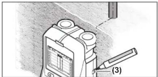
0jil jjgl jg y paas g 5jisiole 5j
1ypaaiu i, syy cksj CwJ U cy dU y
daa o aqily. y jg Jla u y j o
gj16(jj j0o jUio jg
0w osuus cwlj b)g(g,sgw g o 1
Ejugj (3) CwJ JIsioLc Sos (Sg) gij .sis (SjIsioLc
Jgds Jy jn jn jn Jn Jn Jn Jn Jn Jn Jn Jn Jn Jn Jn Jn Jn Jn Jn Jn Jn Jn Jn Jn Jn Jn Jn Jn Jn Jn Jn Jn Jn Jn Jn Jn Jn Jn Jn Jn Jn Jn Jn Jn Jn Jn Jn Jn Jn Jn Jn Jn Jn Jn
Jl Jw loj jg 11) oJw dss n jw g Jg Sg oJol g g Jnloj j0 w Cg L .S Eg