
FPA-2000-SFM - Detector BOSCH - Free user manual and instructions
Find the device manual for free FPA-2000-SFM BOSCH in PDF.
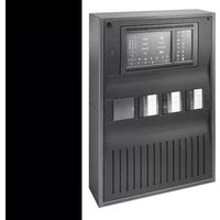


| Product Type | Flame Detector |
| Brand | Bosch |
| Model | FPA-2000-SFM |
| Dimensions (Diameter x Height) | 100 mm x 50 mm (approx.) |
| Weight | 0.5 kg (approx.) |
| Power Supply | 24 VDC (typical) |
| Detection Principle | Infrared (IR) or Ultraviolet (UV) sensing |
| Detection Range | Up to 30 meters (depending on flame size) |
| Response Time | < 10 seconds (typical) |
| Operating Temperature | -10°C to +55°C |
| Humidity Range | 0% to 95% (non-condensing) |
| Protection Rating | IP65 (approx.) |
| Housing Material | Aluminum or Lexan |
| Mounting Type | Wall or ceiling mount |
| Maintenance | Clean lens quarterly; test monthly |
| Safety Compliance | EN 54-10, UL 268 (as applicable) |
| Spare Parts | Lens kit, filter, mounting bracket |
| Repairability | Field replaceable optics and electronics |
| Warranty | 2 years (typically) |
| General Information | Part of Bosch FPA-2000 series; compatible with fire alarm panels |
Frequently Asked Questions - FPA-2000-SFM BOSCH
User questions about FPA-2000-SFM BOSCH
0 question about this device. Answer the ones you know or ask your own.
Ask a new question about this device
Download the instructions for your Detector in PDF format for free! Find your manual FPA-2000-SFM - BOSCH and take your electronic device back in hand. On this page are published all the documents necessary for the use of your device. FPA-2000-SFM by BOSCH.
USER MANUAL FPA-2000-SFM BOSCH
FPA-5000 | FPA-1200 | AVENAR panel 8000 | AVENAR panel 2000 | AVENAR keypad 8000
FPE-8000-SPC | FPE-8000-PPC | FPE-2000-SPC | FPE-2000-PPC | FPE-8000-FMR

en
User Guide
Table of contents
| 1 | For your safety 7 | |
| 1.1 | Operating the touch screen 7 | |
| 1.2 | Maintenance 7 | |
| 1.3 | Usage in accordance with regulations 8 | |
| 1.4 | Skills required by personnel 8 | |
| 2 | For your information 9 | |
| 2.1 | What is new 9 | |
| 2.2 | Open Source license agreement 10 | |
| 2.3 | Calling up the start menu 10 | |
| 2.4 | Changing language display 10 | |
| 2.5 | Warranty and liability 10 | |
| 2.6 | Copyright 10 | |
| 3 | All functions at a glance | 11 |
| 4 | In overview | 13 |
| 4.1 | Operating elements | 13 |
| 4.2 | Status LEDs | 14 |
| 4.3 | Touch screen | 16 |
| 4.4 | Standby screen | 18 |
| 4.5 | Display support information | 19 |
| 5 | Operating principle | 20 |
| 5.1 | Switch on and switch off | 20 |
| 5.2 | Initial setup | 21 |
| 5.3 | Logging on and off | 22 |
| 5.3.1 | Logging on 22 | |
| 5.3.2 | Logging off | 22 |
| 5.4 | Access authorization | 22 |
| 5.5 | Calling up the start menu 23 | |
| 5.6 | Personalized menu | 23 |
| 5.7 | Selecting the menu | 23 |
| 5.8 | Returning to the previous selection | 23 |
| 5.9 | Working with lists | 24 |
| 5.9.1 | Scrolling through lists | 25 |
| 5.9.2 | Various states of list fields | 25 |
| 5.9.3 | Assigning mode | 26 |
| 5.10 | Search Function/Element 26 | |
| 5.10.1 | Search by name | 26 |
| 5.10.2 | Searching by number 27 | |
| 5.11 | Entering numbers and text | 27 |
| 5.11.1 | Changing an entry | 28 |
| 5.11.2 | Deleting all numbers | 28 |
| 5.12 | Changing language display 28 | |
| 5.12.1 | Entering by shortcut | 28 |
| 5.12.2 | Change language by menu 28 | |
| 5.13 | Switching between status bars | 29 |
| 5.14 | Standby | 29 |
| 5.15 | Logical and physical addressing | 29 |
| 6 | Networking via Ethernet | 30 |
| 6.1 | IP settings | 30 |
6.2 Diagnostics 30
7 Remote keypad 32
7.1 Operation and display 32
7.2 Connecting to remote panel 32
8 Alarm 34
8.1 Types of alarm 34
8.2 Entry delays 34
8.3 Day and night mode 35
8.4 Alarm message to the panel 36
8.4.1 Optical and acoustic signals 36
8.4.2 Displaying the detector zones in alarm state 36
8.4.3 Sequence of the alarm messages 37
8.4.4 Information about logical zones in the alarm state 37
8.4.5 The newest message 38
8.4.6 Displaying the individual detectors in a logical zone 38
8.4.7 Information about individual detectors 38
8.4.8 Displaying additional information 39
9 Fire alarm 40
9.1 Evacuation 40
9.2 Optical and acoustic signals 41
9.3 Acknowledging a message 41
9.4 Silence internal buzzer 41
9.5 Activate and silence signaling devices 41
9.6 Resetting signaling devices and transmission devices 41
9.7 Triggering fire verification 42
9.7.1 Alarm verification 42
9.7.2 Starting time to investigate 42
9.7.3 Triggering alarm manually 43
9.8 Resetting alarm message 43
9.9 Bypassing detectors 44
10 Fault message 45
10.1 Calling up fault indication 45
10.2 Fault message on the panel 45
10.2.1 Acknowledging a message 45
10.2.2 Sequence of the fault messages 46
10.2.3 Information about malfunctioning element groups 46
10.2.4 The newest message 46
10.2.5 Displaying individual elements of an element group 47
10.2.6 Information about individual elements 47
10.2.7 Displaying additional information 47
10.2.8 Signals 48
10.3 Resetting fault message 48
10.4 Blocking an element 49
11 Bypass 50
11.1 Menu overview 50
11.2 Bypassing and un-bypassing elements 50
11.3 Displaying and un-bypassing bypassed element groups 50
11.4 Displaying list of all bypassed elements 51
11.4.1 Using the menu 51
11.4.2 Via the status bar 51
11.5 Bypassing/Un-bypassing buzzer 51
11.6 Bypassing/Un-bypassing the output to fault warning routing equipment 52
11.6.1 Bypassing the output to fault warning routing equipment 52
11.6.2 Un-bypassing the output to fault warning routing equipment 52
12 Block 54
12.1 Menu overview 54
12.2 Blocking and unblocking elements 54
12.3 Displaying list of all blocked elements 54
12.3.1 Using the menu 54
12.3.2 Via the status bar 55
13 Diagnostics 56
13.1 Menu overview 56
13.2 Element details 56
13.3 Modules 57
13.4 Hardware 57
13.4.1 Display 57
13.4.2 CAN-Bus 58
13.5 Panel Passport 58
13.6 LED Test on modules 58
13.7 Network services 58
13.7.1 Routing table 58
13.7.2 Consistency check 59
13.7.3 Ethernet ports 59
13.7.4 Send ping command 60
13.7.5 Remote services 60
13.8 Voice alarm systems 61
14 Maintenance 63
14.1 Menu overview 63
14.2 Change language 63
14.3 Activate Outputs 63
14.4 Activate Transmission Device 64
14.5 Bypassing/Un-bypassing buzzer 64
15 Maintenance – walktest 65
15.1 Walktest groups 65
15.1.1 Adding or deleting elements 65
15.2 Starting and ending walktest 67
15.2.1 Starting the walktest 67
15.2.2 Ending the walktest 68
15.3 Ending walktest for all elements 68
15.4 Displaying tested or untested elements 68
15.5 Assigning tested elements to a walktest group 68
16 Maintenance – history log 69
16.1 Selecting filters 69
16.2 Setting filters 69
16.3 Change Filter 70
16.4 Combining several filters 70
16.5 Status bar functions 70
16.6 Printing out data 70
17 Day and night mode 72
17.1 Switching between day and night mode 72
17.2 Showing details 73
17.3 Changing the time for resetting to night mode 73
18 Configuration 75
18.1 Menu overview 75
18.2 Physical node address (PNA/RSN) 75
18.3 Group setting 75
18.3.1 Adding or deleting 75
18.3.2 Change name 77
18.4 Detector sensitivity 77
18.5 Operator 77
18.5.1 Change password 78
18.5.2 Change universal password 78
18.5.3 Set Default Password 78
18.6 Rename elements 78
18.7 Network services 79
18.7.1 Ethernet 79
18.7.2 Change date/time 79
18.7.3 Remote Services 79
18.8 Overview 79
19 Further functions 81
19.1 Menu overview 81
19.2 Change Date / Time 81
19.3 Master password 81
19.3.1 Enter the master password that is valid indefinitely 81
19.3.2 Enter the 24-hour master password 81
19.4 Remote Services 82
19.5 Change password 83
19.6 Performing a fire drill 83
19.7 Alarm Counters 84
20 Reset 85
20.1 Menu overview 85
20.2 Resetting elements 85
21 Control / Monitor 86
21.1 Menu overview 86
21.2 Activate doorholder, control element or HVAC 86
21.3 Go to element 86
21.4 Search for function 86
22 Boot menu 88
Index 89
1 For your safety
Before using the device, familiarize yourself with these instructions. If you do not read and understand these explanations, you will not be able to operate the device faultlessly.
The operating instructions do not do away with the need for training by authorized personnel.

Notice!
The device may only be operated by trained personnel. See Skills required by personnel, page 8.
This user guide does not contain any general or special knowledge about safety issues.
Information on such issues is only given to the extent that it is needed for operation of the device.
Ensure that you are familiar with all safety-related processes and regulations in your area. This also includes how to behave in the event of an alarm and the initial steps to take if a fire breaks out.
The user guide is a statutory part of the system and must be made known to the new owner if the system is ever sold.

Notice!
The personal access code (consisting of user ID and password) must not be made known to third parties.

Warning!
The device must be shut down by power button. Don't unplug the device from power supply while the system is in operation. This could result in the damage of the device. After shutting down the device correctly restart it via the power button.
1.1 Operating the touch screen

Caution!
Do not use any pointed or sharp objects (e.g. screw drivers, pens, etc.) when operating the touch-sensitive display. The touchscreen may not be exposed to direct sunlight. Both can seriously damage the touchscreen.

Caution!
The recalibration of the panel touchscreen must be performed at least once a year. Otherwise the operation of the panel may be limited or become even impossible without prior recalibration.
1.2 Maintenance
Clean the touch screen and surfaces with a slightly damp soft cloth only. Do not use any cleaning agents and make sure that no liquid enters the inside of the device.
1.3 Usage in accordance with regulations

Notice!
Terminology
The term Walktest, which is used in the fire panel and in the documentation, corresponds to the EN54-2 standard term Test condition.
The panel controller is designed for operating the AVENAR panel 8000/2000 fire panel. It can perform the following tasks:
- Displaying and processing various message types such as alarm and trouble messages
- Bypassing, blocking and resetting elements – Monitoring and controlling of sounders and outputs
- Performing a walktest
- Display diagnostic information about every LSN element
- Configuration of detectors (short texts and detector sensitivity)
- Performing a drill
- Saving, displaying and printing out events
- Switching the system to day or night mode.

Notice!
The manual control of evacuation zones and the outputs connected to fire protection equipment (e-Matrix) are user features without regulatory requirements, as these features are not within the scope of EN54-2.
1.4 Skills required by personnel
Display of event messages on the panel controller must only be processed by trained personnel.
The system walk test and detector configuration must only be performed by trained, authorized personnel.
2 For your information
This operation guide contains important information and notes on operating the AVENAR panel 8000/2000.
Using the step-by-step directions, you can familiarize yourself with the individual functions:
- In overview, page 13 provides an overview of the operating and display elements and the touch screen.
- In Operating principle, page 20, you will learn how to navigate through the individual menus and which selection possibilities are available to you.
Each function is described in detail in an individual chapter.
You will find specific topics in the table of contents. If you are already practiced in the handling of menus, you can use the overview of all menus in All functions at a glance, page 11.
2.1 What is new
The AVENAR panel 8000/2000 is the successor panel of the FPA-5000/FPA-1200 modular fire panel. AVENAR panel 8000/2000 combines a new and powerful panel controller platform with all the well-known stable safety features.
When operating the AVENAR panel 8000/2000 please note the following important innovations:
Physical node address (PNA/RSN)
The physical node address of the panel is set in the panel firmware when switching on the panel for the first time. The physical node address dialog replaces the mechanical rotary switches.
For details see Initial setup, page 21.
Power button
The panel must be switched on and off with a power button which is located at the right side of the panel. Also a reboot of the panel is done via the power button.

For details see Switch on and switch off, page 20.
Calibration of the touchscreen
The calibration of the touchscreen is started via the boot menu, which can be called up during the boot process of the panel, for details see Boot menu, page 88.
Refer to
- Boot menu, page 88
2.2 Open Source license agreement

Notice!
Bosch Sicherheitssysteme GmbH uses open source software within this product. The declaration of the components and their respective licenses can be found on http://www.boschsecurity.com/oss/.
2.3 Calling up the start menu
Press

You can use this key to return from any submenu back to the start menu.
2.4 Changing language display
The panel language can be changed quickly with a shortcut:

- Press to open the start menu.
- Press 1 on the alphanumeric keypad.
- Select OK to confirm the entry or Cancel to cancel the operation. A list of the existing languages is displayed.
- Select the language you require. All display elements are now shown in the selected language.

Notice!
After a system reboot following a power cut or battery failure, the default language set in the FSP-5000-RPS is displayed again.
2.5 Warranty and liability
Warranty and liability claims for personal and property damage are excluded if these were caused by one or several of the following causes:
- Use of the fire panel contrary to the regulations
- Improper set-up, installation, start-up, operation or maintenance
- Disregarding of the user manual – Subsequent constructional changes
- Faulty repairs – Catastrophes, influence of foreign bodies, and force majeure.
Without the permission of Bosch, no changes or additions to or rebuilding of the panel including the panel controller may be undertaken.
Rebuilding requires written permission. In case of non-approved constructional changes, any warranty claims against Bosch are voided.
2.6 Copyright
Bosch Sicherheitssysteme GmbH, Robert-Bosch-Ring 5, 85630 Grasbrunn, Germany retains the complete copyright to the whole documentation. Without the express written permission of Bosch, no part of these documents may be duplicated or transmitted in any form.
Bosch reserves the right to make changes to this manual without prior notice.
3 All functions at a glance
Main menu
| Bypass Block Diagnostics | |
| Maintenance Configuration | |
| Switch to day mode Further functions | |
| Control Monitoring Reset |
Bypass/Block
| BypassBlock | -> Show blocked/ bypassed devices | Select by number | Bypass buzzer Printer | |
| NAC Transmission device | HVAC Doorholder | |||
| Detector Logical zone Extinguishing system | Annunciator | |||
| Bypass/ Block group | More... -> Control element Interface | module |
Diagnostics
| Diagnostics -> | Element details | Modules |
| Hardware | Panel passport | |
| LED test on modules | History log | |
| Network services | VAS |
Maintenance
| Maintenance | -> | Walktest | Change language |
| Activate outputs | Activate transmission device | ||
| History log | Bypass buzzer |
Configuration
| Configuration | -> | Set Physical Node Address (PNA/RSN) | Set groups |
| Detector sensitivity Operator | |||
| Rename elements | Overview | ||
| Network services | About ... | ||
Further functions
| Further functions -> Change | date / time Master password | |
| Remote Services Change password | ||
| Drill Alarm counters |
Control / Monitoring
| Activate doorholder Activate HVAC | |
| Activate control element Search function | |
| Go to element |
Reset
| Reset -> Event type Scope | |||
| Logical zone Detector | |||
| This panel | |||
4 In overview
This chapter contains information about the following elements of the panel controller:
- Operating elements, page 13
- Status LEDs, page 14
- Touch screen, page 16
- Display support information, page 19

1 Status LEDs 6 Display a list of the networked panels and establish a remote connection with a networked panel 2 Information bar 7 Display and control all alarm zones 3 Status bar 8 Log-in to the panel and call up personalized menu 4 Open start menu 9 Silence internal buzzer 5 Go back 10 Function keys, programmable 11 Display support information
4.1 Operating elements
Fixed keys
To select a function, touch the appropriate key.
The following functions can be executed with the fixed keys on the bottom of the display:
![graph TD A["House"] --> B["←"] B --> C["Pine Pyramid"] C --> D["Right Arrow"]](/content/2026/06/1365663/images/d7451ec22ece507c2447cc10cc9abb6f954a79ce83c74a2b8ded1145cead0518.jpg)
"Home" key. Call up the start menu.
Return to the previous selection.
Display a list of the networked panels and establish a remote connection with a networked panel or a remote keypad.
Display and control all alarm zones.
 | Log in and out: Enter user ID and password or call up personalized menu, if you are already logged in. |
 | Temporarily silence the internal buzzer. |
 | "Left arrow" key. Move the cursor one place to the left on the search screen. |
 | "Right arrow" key. Move the cursor one place to the right on the search screen. |
 | "Double arrow" key. Switch between status bars if two or more are available. Call up the status bar to scroll rapidly through lists. |
 | "Enter" key. Confirm an alphanumeric entry. Confirm an entry that is not confirmed by selecting the OK field on the touch screen. |
Alphanumeric keypad
Entry of letters, special characters, and numbers.
Function keys
There are three function keys F1, F2 and F3 which are freely programmable with frequently used functions of the panel via the Programming Software. If a function key is active it is marked with a green bar.
Alphanumeric keypad
Entry of letters, special characters, and numbers.
4.2 Status LEDs
18 status LEDs show information on the operating status of the fire panel.
| Color* Meaning | |
 | R Fire alarm |
 | R Evacuation ongoing |
 | R Fire alarm transmission activated |
 | R Fire protection equipment activated |
 | Y Maintenance mode |
 | Y Day mode/delays active |
 | Y General disabled |
 | Y General fault |
 | Y** Fire detector fault / disabled |
 | Y** Signaling device fault / disabled |
 | Y** Alarm transmission device fault / disabled |
 | Y** Output to fire protection equipment fault / disabled |
 | Y Power fault |
 | G Power available |
 | Y System/panel fault |
 | G System in operation |
 | R Programmable LED for a self-defined alarm |
 | Y** Programmable LED for a self-defined fault/diasablement |
| *Y=yellow, R=red, G=green**blinking: fault, steady: disabled |
The LEDs for the status of devices like detectors, signaling devices, alarm transmission devices, and the outputs to fire protection equipment always light up in combination with the general fault or general disabled icon according to their status. Additionally, in case of a fault, the LED of the respective element blinks while the LED indicating the general fault lights up steadily yellow.
Example:


1 Fault indication for a device 2 Device disabled 3 Device disabled and in fault status

Notice!
As neither the panel nor the power supply can have the status "disabled", the system fault

and the power fault icon light up steadily in yellow in the status "fault".
4.3 Touch screen

Caution!
Do not use any pointed or sharp objects (e.g. screwdrivers, pens, etc.) when operating the touch-sensitive display. The touchscreen may not be exposed to direct sunlight. Both can seriously damage the touchscreen.

| 1 | Information bar 4 Fixed operation keys | ||
| 2 | Menu field | 5 | Alphanumeric keyboard |
| 3 | Status bar | 6 | Function keys, programmable |
Information bar
The information bar displays general information as text or icons.
| Icon | Meaning |
 | No connection established.Only displayed on the panel. |
 | No connection established.Only displayed on the keypad. |
 | Remote connection established.Operator has restricted use of the remote panel: no control, only monitoring. |
 | Remote connection established.Operator is in full control of the remote panel. |
 | Remote connection established.A remote operator is in full control of the panel.The panel is locked for local access. |
 | Ground fault detected. |
 | Operator logged in. |
| Text Meaning | |
| Panel 4-1 Logical node address | |
| Level 3 logged in Access level of | the operator who is logged in.Possible levels: 2, 3 or 4Only displayed in the main menu. |
| Bypass Block\Block\Detector Menu | nu path of the selected menuFor reasons of space it is not always possible to display the complete path. |
Menu field
To select a main menu, touch the corresponding menu field on the touch screen. In All functions at a glance, page 11, there is an overview of all main menus with their respective submenus.
Status bar
| 0Fire | 0Control | 8Fault | 0Bypass Status |
This status bar is available on each menu. In addition, other status bars are offered in some menus; see also Switching between status bars, page 29:
The leading number specifies the number of elements in the respective state:
Fire Number of groups that have triggered a fire alarm
Control Elements that are activated
Fault Elements that have reported a fault
Bypass Disabled elements
In addition it is possible to display an overview of the type and nature of all message types received by the panel:
Status Display of a list of the various message and status types and the number of elements in the respective state
To display the individual elements, touch the relevant field with your finger.
The Control and Fault status fields are identified by the letters "B" and/or "C":
- "B" means that controllers for type B fire protection equipment (G-B) are affected (e.g. control elements without acknowledgement).
- "C" means that controllers for type C fire protection equipment (G-C) are affected (e.g. extinguishing systems).
4.4 Standby screen
When the touchscreen is not operated, its backlight switches off after 5 minutes.

Notice!
In case of an active alarm or fault message, the backlight switches off after 60 minutes. The display switches back to this message from any other element of the menu after 30 seconds.
If the screen is black, touch it gently to display the standby screen. The following information is displayed on the standby screen:
- Date

Depending on the configuration, additional information may be displayed.
In a networked fire detection system, further icons can be displayed in the standby display depending on the network setting.
4.5 Display support information
To display the address of the company providing the support, please press the company logo in the upper right corner of the panel screen.


Notice!
Information concerning support is only displayed if the information has already been entered in FSP-5000-RPS.
5 Operating principle
5.1 Switch on and switch off
Power button
The fire panel must be switched on and off with a power button which is located at the right side of the panel. Also a reboot of the panel is done via the power button.


Warning!
Don't unplug the panel for restarting it! Always use the power button. Unplugging the running panel can cause a serious damage of the hardware and software.
The functions of the power button are:
- Press once shortly: Start the panel
- Press once shortly at a running panel: Shut down the panel

Notice!
A confirmation sound is played when the shutdown-sequence is starting. The shutdown is
completed when the “general fault” and the “system/panel fault” status LEDs light up. Wait until the shutdown is completed before you interrupt the power.

Notice!
After having shut down the panel please interrupt the power supply. If a panel was shut down but is not unplugged, after 10 seconds a warning tone will sound as a reminder.
- Press for 8 seconds: Interrupt the panel and reboot it (for example in case of a software failure).

Warning!
You must only use this way of interrupting the panel if the system does not react anymore or if you are asked to do so in case the panel ran into the safe state.
Safe state

Notice!
To avoid the panel running into a safe state, do not reboot the panel twice within 100 seconds.
If the panel reboots twice within 100 seconds (either because of a system error or intentionally for example during the initial set-up) it runs into a safe state which can be ended by a manual restart only. A warning tone sounds and a message appears on the screen. In this case, please follow the instructions on the display.
5.2 Initial setup
When you start the panel for the first time, you must perform the following steps:
Calibrate touch screen
When initially starting the panel, first of all you must calibrate the touch screen:
- Switch on the panel by applying power or pressing the power button. The touchscreen calibration procedure will start automatically if required.
- Perform the calibration by following the instructions on the screen. The boot process will automatically continue after the calibration was completed.
Set time and date
Touch the field you require and enter the correct value. For details see Change Date / Time, page 81
Set physical node address (PNA/RSN)
You must set the physical node address (PNA/RSN) when switching on the panel for the first time.

Notice!
There are no mechanical rotary switches.
The physical node address must be identical with the number configured in the programming software. After a change of the physical node address, a reboot of the panel is required. To change the physical node address enter a number between 1 and 64. Choose OK and reboot to make the change effective.
Use Ethernet settings
Check Use Ethernet settings if the panel is used within an Ethernet network.

Caution!
If you check Use Ethernet settings it is absolutely necessary to set the panel IP address via Configure Ethernet.
Use RSTP
Check Use RSTP to activate Ethernet redundancy. For details see Ethernet redundancy.
Configure Ethernet
Check Configure Ethernet to use the standard IP address of the panel.
Reboot
After having made all the necessary settings, reboot the panel by pressing Reboot.
5.3 Logging on and off
To gain access to access levels 2 to 4, it is necessary to log on. The prerequisite is that you have access authorization.
Notice!

To log on, you need a user ID and password. Depending on your access authorization, you can use only particular functions.
In the following cases, you will be asked to enter a password:
You are not logged on and want to select a function for which a password is required.
You are already logged on but a higher access authorization is required for the function you have selected.
5.3.1 Logging on
To log on to the panel controller:
Press the login key

The login window is displayed:
- Enter your user ID in the first field. Refer to Entering numbers and text, page 27 for information on how to enter numbers.
- Enter your password in the second field.

Notice!
The default password is: 000000. For security reasons please change this password, see Change password, page 83.
- Select OK to confirm the entries or Cancel to cancel the operation.
Refer to Change password, page 83 for information on how to set up your own password.
The standby display is shown.
As long as an operator is logged on, the key icon will be displayed on the information bar. In addition, the user ID of the user who has logged on is displayed on the start page on the information bar.

Notice!
In the FSP-5000-RPS programming software, a time span can be specified after which an operator who is logged on to the panel controller is logged off.
5.3.2 Logging off
- To log off from the panel controller, press : An input window with the request Log off? is displayed:
- Select Yes to confirm the request or No to cancel the operation.

5.4 Access authorization

Notice!
Depending on your access authorization, you can only use certain functions of the panel controller.
If you select a function for which a particular access authorization is required and no user with the appropriate authorization is logged on, you will be asked to enter your user ID and password.
Access authorizations are assigned for access levels two to four. Only a few functions can be used on access level one, while all functions can be used on access level four.
To check the access authorization of the person who is logged in, press after logging in:
The relevant access authorization is displayed.
5.5 Calling up the start menu
Press the "home" key to return to the start menu from any submenu.


Notice!
The display changes from each menu element to the standby display if no entries are made after 5 minutes, in case of an alarm or a fault message after 60 minutes, see also Standby screen, page 18.
If the screen is black, touch it gently to display the standby screen.
5.6 Personalized menu
Via the FSP-5000-RPS programming software you can configure your personalized start menu which displays up to eight functions you need most often directly when you log in to the panel.
To retrieve the personalized menu log on to the panel: Press the login key and enter your user ID and password.

To change back from the personalized menu to the common main menu press the "home" key.

To change back to the personalized menu from any other screen, press the login key.

5.7 Selecting the menu
In order to select a menu in the main menu, touch the field you require with your finger:
The submenus are displayed.
To select a submenu, gently touch the required field.
5.8 Returning to the previous selection
To return to the previous selection, press the "Back" key:

5.9 Working with lists

| 1 | List 4 Scroll up / scroll down | ||
| 2 | List field 5 Function fields | ||
| 3 | Search mask |
In many menus, elements are displayed in lists. The elements are sorted either by description or address. Up to three different sorting criteria can be offered:
- By description: sorted by description in alphabetical order; address allocation also given.
- By number: sorted in ascending order by number (logical or physical address); description also given.
- By number (no description shown): by number (logical or physical address) in ascending order; the numbers are displayed in number blocks and the description is not given. This list is only offered when detectors and logical zones are being selected.
Example:
To display a list of all existing detectors sorted by description in the Bypass submenu, select the following in the start menu:
- Bypass Block
- Bypass
- Detector
Three sorting criteria are offered for selection:
- By description
- By number
- By number (no description shown)
Select By description.
A list of all detectors is displayed, sorted in alphabetical order.
5.9.1 Scrolling through lists
On the display, only a limited number of list fields can be displayed.
Select the "up arrow" key to scroll back through a long list:

Select the "down arrow" key to scroll forward through the list:

An arrow is only displayed if scrolling is possible.
Rapid scrolling:

To scroll quickly through a list, press the "double arrow" key on the keypad or on the status bar of the display.
A scrollbar appears on the status bar:

Gently touch the horizontal line to jump to a particular place.
To jump to the beginning of a list, touch:

To jump to the end of a list, touch:

5.9.2 Various states of list fields
Various states can be assigned to an element or an element group, depicted by a list field. The following table provides information about the possible states:
| List field State of list | field | Meaning |
 | normal Element in normal state | |
 | marked Selected element | |
 | Mode assigned The element was assigned the bypassed mode; seeAssigning mode, page 26. | |
 | Mode assigned and marked | The selected element has already been assigned a particular mode. It is selected in order to reset it to the original mode; a bypassed element is unbypassed, for example. |
 | In reset mode The resetting of the element is not yet complete. | |
"Bypass" menu
In the Bypass menu, list fields can display additional information; see the following table:
List field In the Bypass menu

The bypassed element is in alarm mode. If it is un-bypassed, it triggers a fire alarm.
To display more information, press the right-hand field.

Display a bypass group that consists of several elements. In order to display a list of all elements of the bypass group, press the right-hand field.
5.9.3 Assigning mode
A mode like Bypassed, Walktest etc. can be assigned to selected elements.
To assign a mode to selected elements, select the corresponding function field.
In the following example, a detector is assigned bypassed mode in the Bypass Block menu:
- Select the list fields you require from the list.
The list fields are marked.
- Select the Bypass function field.
The detectors are bypassed. The list fields are highlighted in a dark color.
The sand glass icon indicates an entry that is still being processed by the system.


Notice!
In the Bypass submenu, the function fields have an additional selection option; see Displaying and un-bypassing bypassed element groups.
5.10 Search Function/Element
In lists, a particular element can be searched for and displayed using the search screen. The following search criteria are offered:
- By description: The element is searched for in the list by its description.
- By number: The element is searched for in the list by its number. In some menus, the By number (no description shown) search function is offered.
In the Search function / element main menu, it is possible to search for all elements connected to the system and all functions offered in the panel controller, as well as device descriptions, regardless of which menu they appear in; see Search Function/Element.
5.10.1 Search by name
To search in the By description list for a particular element, enter the name of the element in the search screen.
Entering numbers and text explains how to enter text.
Enter the initial letter and, if necessary, other letters.
The name is automatically completed once it has been uniquely recognized. The list field of the element you are searching for is displayed at the beginning of the list.

Notice!
The more accurately the description of an element is entered in the FSP-5000-RPS programming software, the easier the search by name will be.
5.10.2 Searching by number
To search in the By number and By number (no description shown) list for a particular element:
- Enter the first digit, for example 1.
- Press the "Enter" key to confirm the entry.
If the entry of another number is possible, a second search window is displayed.

Notice!
If you are not offered another field, there is no element with the addressing you have searched for.
- Enter the next digit and confirm your entry with the "Enter" key.
- If necessary, enter further digits until the number is shown in full. You must confirm each entry with the "Enter" key.
The list field of the element you are searching for is then displayed at the beginning of the list.
5.11 Entering numbers and text
| Key Character | |
| 0 -,-_ | ,-_0 |
| 1 □ | □ 1 |
| 2 ABC | ABCabc2 |
| 3 DEF | DEFdef3 |
| 4 GHI | GHIghi4 |
| 5 JKL | JKLjkl5 |
| 6 MNO | MNOmno6 |
| 7 PQRS | PQRSpqrs7 |
| 8 TUV | TUVtuv8 |
| 9 WXYZ | WXYZwxyz9 |
| * | * |
| # | |
You can enter letters and numbers with each of the keys depicted.
Press the corresponding key on the keypad until the required letter or number is displayed.

Notice!
Only numbers can be entered in the search screen for the By number and By number (no description shown) lists. In the search screen for the By description list, both letters and numbers can be entered.
Quick entry:
In order to enter text quickly, press the "Enter" key after entering each letter.
This takes the cursor to the next free character and you can continue with entering the next letter.
5.11.1 Changing an entry
- In order to change a number, press the "left arrow" or "right arrow" keys until the cursor marks the number in the search screen that is to be replaced.
- To overwrite the marked number, press the key with the required number until the number you require is displayed in the search screen.
5.11.2 Deleting all numbers
- In order to delete all numbers in the search screen, press the "left arrow" key until the cursor marks the first number.
- Enter a new number using the number pad. All numbers up to the digit entered are deleted.
- If you wish to, continue entering the numbers.
5.12 Changing language display
There are two ways to select another language display:
- By entering a shortcut
- Via a menu selection
- By entering a shortcut - Via a menu selection
5.12.1 Entering by shortcut
The panel language can be changed quickly with a shortcut:

- Press to open the start menu.
- Press 1 on the alphanumeric keypad.
- Select OK to confirm the entry or Cancel to cancel the operation.
- Press to open the start menu.
- Press 1 on the alphanumeric keypad.
- Select OK to confirm the entry or Cancel to cancel the operation.
A list of the existing languages is displayed.
- Select the language you require.
All display elements are now shown in the selected language.

Notice!
After a system reboot following a power cut or battery failure, the default language set in the FSP-5000-RPS is displayed again.
5.12.2 Change language by menu
- In the start menu, select Maintenance
- Change language
- In the start menu, select Maintenance
- Change language
A list of the languages which can be selected is displayed.
- Select the language you require.
All display elements are now shown in the selected language.
5.13 Switching between status bars
The status bar offers further functions, display and selection options.
If the "double arrow" symbol is displayed in the status bar, it is possible to switch to the
status bar of the start menu. To do this, press the "double arrow" key on the keypad.
5.14 Standby
When the touchscreen is not operated, its backlight switches off after 5 minutes.

Notice!
In case of an active alarm or fault message, the backlight switches off after 60 minutes. The display switches back to this message from any other element of the menu after 30 seconds.
If the screen is black, touch it gently to display the standby screen.
5.15 Logical and physical addressing
When addressing elements, there is a distinction between logical and physical addressing:
| Physical | |||
| Elements Modules Loop Element | |||
| Numbers 5 1 4 | |||
| Logical | |||
| Elements Zone Element | |||
| Numbers 3 4 | |||
Examples:
Element with physical addressing: 5.1 - 4
Element with logical addressing: 3 - 4
6 Networking via Ethernet
6.1 IP settings
To modify values for Ethernet settings or to configure these for the first time, select in the start menu:
- Configuration
- Network services
- Ethernet. The Configure Ethernet screen is displayed.
- Activate the checkbox Use Ethernet settings.
- Select IP settings. The values for IP address, network screen, default gateway, multicast address and port number are indicated. When you commission the panel controller for the first time, all values are set to "0".
- Select Default settings to overwrite these values with the default settings saved in the panel controller (recommended!). The IP address in this case corresponds to the stored default IP address, the last number of which matches the physical node address (PNA/RSN) that was set during installation at the panel controller.
- If the planned configuration requires a change to the default values:
Touch the field containing the value to be changed. Use the arrow keys on the operating panel to select the desired numbers and modify the values using the number keys on the alphanumeric keypad.
Or:
Touch the Change field. Touch the field containing the number block to be changed. Use the arrow keys on the operating panel to select the desired numbers and modify the values using the number keys on the alphanumeric keypad.
Touch OK to apply the changes or Cancel to discard the changes. You are returned to the initial Configuration IP screen.
- Select OK to apply the changes to the IP settings or Cancel to discard the changes. You are returned to the Configure Ethernet screen.
- Select OK to confirm application of the Ethernet settings (Use Ethernet settings) or Cancel to exit the screen without activating the Ethernet settings.

Notice!
Changes to Ethernet settings take effect after restarting the panel.
6.2 Diagnostics
Diagnostics information and help materials for pinpointing problems in a network can be found under menu item Diagnostics - Network services. Information is provided on the following topics:
- Routing table
Information concerning the accessibility of all nodes within the system network via the respective interface.
- Ethernet ports
Information concerning different parameters and the status of the two Ethernet interfaces available at the panel controller.
- Send ping command
Sending of a ping command to a specific IP address to check the availability of other nodes in the network.
- Consistency check
The check performed determines whether the Ethernet configuration from FSP-5000-RPS corresponds to the configuration entered at the panel controller. In the event of discrepancies, a fault message is displayed.
- Ethernet redundancy
Information concerning redundancy. The RSTP parameters of the RSTP panel and those of the root bridge are displayed.
- Remote Services
Information concerning the features and the status of the Remote Services.
Further information can be found in Network services, page 58.
7 Remote keypad
7.1 Operation and display
A remote keypad is by default programmed so that messages are displayed, even if no operator is logged in. In this case, the operation of all functions with permission level =1 is possible.

Notice!
It is possible to specify in the FSP-5000-RPS programming software that if no operator is logged in, only the standby screen is displayed. In this case, no LEDs are activated and no messages are displayed. In order to activate the LEDs and display messages, an operator with an access authorization >1 has to log in.
If the remote keypad is not connected to a panel, the following symbol is displayed on the standby display and in the status bar:

Notice!
In the FSP-5000-RPS programming software, a time span can be specified after which an operator who is logged in to the panel controller is logged out.
7.2 Connecting to remote panel
Through the remote keypad, it is possible to establish a connection to a remote panel.
- Press .

The display shows a list of available network nodes.
- Select a node and press OK.
- Press OK again.
The connection to the remote panel is established.
Depending on the type of connection, a symbol is displayed on the standby display and in the status bar:

- : The operator is in full control of the remote panel

- : The operator has restricted use of the remote panel: no control, only monitoring.

Notice!
When another operator is already locally logged in to the remote panel, a connection with restricted use is established. The local operator has to log out first before a connection with full control can be established.

Notice!
When a connection with full control of the remote panel is established, the remote panel is locked for local access. The standby display and the status bar of the remote panel indicate
locked access by this symbol:


Notice!
It is possible to establish a connection to a remote panel through another panel as well.
Closing the connection to remote panel

- Press .
- To confirm press Yes.
√ The connection to the remote panel is closed.
8 Alarm

Notice!
Information on how to handle a fire alarm can be found in Fire alarm, page 40.
This chapter contains information about the following points:
- Types of alarm, page 34
- Entry delays, page 34
- Day and night mode, page 35
- Alarm message to the panel, page 36
Refer to the Fire alarm chapter for the following topics:
- Acknowledging a message, page 41 – Silence internal buzzer, page 41
- Activate and silence signaling devices, page 41
- Resetting signaling devices and transmission devices, page 41
- Triggering fire verification, page 42
- Resetting alarm message, page 43
- Bypassing detectors, page 44

Notice!
Depending on the configuration, the manner in which alarm displays are shown and handled in this guide may differ from the guide on the system.
8.1 Types of alarm
On the panel controller, a distinction is made between the following types of alarm:
- Fire
- Heat
- Smoke
- Water
- Supervisory
Depending on the configuration, external transmission devices (e.g. fire department), notification appliances (e.g. sirens and/or strobes) and fire protection systems (e.g. sprinkler systems, fire doors) are activated.

Notice!
If an alarm delay is set for the detector triggering the alarm, the alarm signal is not transmitted immediately and the message can be checked; see Entry delays.
8.2 Entry delays
To prevent false alarms, it is possible to delay the transmission of the first alarm signal. The transmission device to the fire department is not activated immediately in this case. During the delay, the message can be checked to ensure it is correct.
The FSP-5000-RPS programming software can be used to program various strategies for avoiding false alarms. These strategies are principally used in fire detectors but can also be assigned to any other detector, depending on how it is configured.
The alarm delays that can be shown in the panel controller display are explained below.
Alarm verification
When the alarm message is acknowledged on the panel controller, a time to investigate is started. During this time, the message in the place where the detector generating the alarm is located must be checked to ensure it is correct. The duration of the verification time can be freely configured for every detector. See also Fire alarm and Triggering fire verification.
If it is determined during the test that the alarm is genuine, an alarm can either be triggered manually or by activating a manual call point. The transmission device to the fire department is activated.
Depending on the configuration, a pre-alarm is displayed for the following alarm delays:
- Intermediate alarm storage
If a detector with intermediate alarm storage triggers an alarm, this is displayed as a pre-alarm on the system. The transmission device to the fire department is not activated. The detector generating the alarm is reset after the first signal.
The pre-alarm becomes an alarm if the same detector triggers an alarm signal again within a set time. The time until a main alarm is triggered is shown on the display. The transmission devices and signaling devices are activated.
– Dual-detector dependency
If a detector triggers an initial alarm within a dual-detector dependency, then this is displayed on the system as a pre-alarm. The transmission device to the fire department is not activated. The detector generating the alarm is reset after the first signal.
The pre-alarm becomes the main alarm if a second detector in the same logical zone triggers an alarm. The transmission devices and notification appliances are activated.
- Dual-zone dependency
If a detector triggers an initial alarm within a dual-zone dependency, then this is displayed on the system as a pre-alarm. The transmission device to the fire department is not activated. The detector generating the alarm is reset after the first signal.
The pre-alarm becomes the main alarm if a second detector in a different logical zone triggers an alarm. The transmission devices and signaling devices are activated.
8.3 Day and night mode

Notice!
Depending on the configuration, the manner in which the difference between day and night mode is displayed may differ from that on the system.
Depending on the configuration, an incoming alarm is handled differently in day and night mode:
Night mode

Night mode has the highest security level. Depending on the configuration, the alarm message is generally transmitted to the fire department without a delay.
Signaling devices (e.g. sirens) and transmission devices to the fire department or fire protection systems are activated.
If the transmission device to the fire department is activated, the icon lights up red. Depending on the configuration, a detector in night mode triggers a pre-alarm if intermediate alarm storage is used as an alarm delay for this detector.
Day mode


Notice!
Depending on the security level in question, not all detectors can be switched to day mode.
Depending on the configuration, a distinction is made between the following possible alarm delays in day mode:
- Alarm verification
- Pre-alarm
A pre-alarm is displayed for the following alarm delays:
- Intermediate alarm storage – Dual-detector dependency
- Dual-zone dependency
For a detailed description of the various alarm delays, see Entry delays.
- Internal alarm
An alarm that is reported to the panel in day mode. No transmission devices to the fire department are activated.
8.4 Alarm message to the panel
The following description has been written on the basis of a sample fire alarm message.
8.4.1 Optical and acoustic signals
- The LED alarm icon lights up red.
- An internal buzzer sounds; see also Silence internal buzzer, page 41.
- Depending on the configuration, sounders and/or visual notification appliances (e.g. sirens, strobes) are activated.
If the transmission device to the fire department is activated, the LED icon lights up red.
8.4.2 Displaying the detector zones in alarm state
The number of messages in question is displayed on the status bar.

Notice!
First of all, the logical zones in which one or more detectors have triggered an alarm are listed. To display the individual detectors, select the logical zone you require. See also Displaying the individual detectors in a logical zone, page 38.
The individual messages are shown in the display:
- List fields with white background: unacknowledged alarm messages
- List fields without distinction: acknowledged alarm messages
Logical Zones

Notice!
A maximum of four alarm messages can be displayed on the display simultaneously. Only fields that can be operated are displayed (e.g. Acknowledge and Reset).
If more than four alarm messages have been received, scroll through the list in order to display the next messages.

Notice!
The latest message is always displayed at the end of the list.
Display during an alarm
The buttons located beneath the alarm message on the display can be used to initiate the corresponding actions:
| Acknowledge | Signals off Signals | on Reset |
- Acknowledge: Touch this button to acknowledge all of the alarm messages shown on the display; see also Acknowledging a message.
- Signals off: Touch this button to switch off activated external notification appliances; see also Switching external signaling devices on and off.
- Signals on: Touch this button to switch on deactivated external notification appliances; see also Switching external signaling devices on and off.
- Reset: Touch this button to reset all of the alarm messages shown on the display; see also Resetting alarm message.
8.4.3 Sequence of the alarm messages
The messages are displayed in chronological order.
- The newest alarm message of a logical zone is always displayed at the end of the list.
- The first and oldest alarm message of a logical zone is displayed at the beginning of the list. The next three messages are displayed as you scroll through the list.

Notice!
30 seconds after the last entry (e.g. after scrolling through the list), the first and oldest alarm is displayed at the beginning of the list again.
8.4.4 Information about logical zones in the alarm state
The alarm message contains information about:
- The element category
- The message type
- The address of the detector group
- The number of detectors that have triggered an alarm in the respective logical zone
- The message number
- Depending on the configuration, additional information such as the installation location
Example:
| Fire Zone 00005 | |||
| #001 Office 1 (6) |
Message type
The message type Fire is reported.
Depending on the configuration, the message type may be defined more specifically, e.g. Fire PAS for a fire alarm with alarm verification.
Address of logical zone
00005: the fifth logical zone triggered the first fire alarm.
Number of detectors
(6): In the fifth logical zone (00005), six detectors (6) triggered a fire alarm.
For logical zones that only consist of one element, no number of detectors is displayed.

Notice!
Depending on the configuration of the system, either the logical or physical address of the detector is displayed.
Message number
The alarm messages are numbered chronologically.
The message number in the second line indicates the sequence in which the alarm messages arrived.
001: The first alarm message that came in.
Depending on the configuration, additional information is displayed in the second line, such as the installation location of the logical zone.
8.4.5 The newest message
The latest message is always displayed at the end of the list.
The message number (e.g. #008) of the latest message indicates the total number of logical zones in which one or more detectors have triggered an alarm.
8.4.6 Displaying the individual detectors in a logical zone
To display the individual detectors in a logical zone, select the logical zone you require.
The alarm messages for the individual detectors are listed.
8.4.7 Information about individual detectors
Each alarm message contains information about:
- The element category
- The message type
- The detector address
- The message number
- Depending on the configuration, additional information such as the installation location
Example:
| Fire Detectors 000 | 05 - 004 | |
| #002 Office 1 |
Message type
Refer to Information about logical zones in the alarm state for information on the type of message.
Message address
In this example, the following detector has triggered a fire alarm:
0005 - 004: the fourth detector (004) in the fifth logical zone (00005).
If the detector number, in this case (004), is not displayed, this is the alarm message for the logical zone.

Notice!
Depending on the configuration of the system, either the logical or physical address of the detector is displayed.
Message number
For information on the message number (#002), see Information about logical zones in the alarm state.
Depending on the configuration, additional information is displayed in the second line, such as the installation location of the detector or the detector type.
To display more information about an alarm message, see Displaying additional information.
8.4.8 Displaying additional information

Notice!
By way of example, an action text can be entered for every detector type in the FSP-5000-RPS programming software.
To display further information about the individual detectors, select the alarm message you require.
The following information is displayed:
- Element category
- Message type
- Date and time of the message
– Physical and logical addressing of the detector
- Only for LSN detectors: specification of the detector type
- Action text (depending on the configuration)
9 Fire alarm

Notice!
Detailed information about types of alarms, alarm delays and the panel controller display can be found in Alarm, page 34.
This chapter contains information about the following points:
- Optical and acoustic signals, page 41
- Acknowledging a message, page 41 – Silence internal buzzer, page 41
- Activate and silence signaling devices, page 41
- Resetting signaling devices and transmission devices, page 41
- Triggering fire verification, page 42
- Resetting alarm message, page 43
- Bypassing detectors, page 44
Signaling fire alarms
A fire alarm is signaled optically and acoustically on the panel through:
- Displaying the logical zones on the display

- Lighting up the "Alarm" LED icon
- An internal buzzer sounds on the system.

Notice!
Alarm messages have the highest priority compared with all other message types. If a fire alarm is reported, the system switches automatically to alarm indication.
9.1 Evacuation
You can manually control all available evacuation zones.

Press the evacuation button to open the list with all available evacuation zones. To search for a specific zone, enter the number of a group of notification appliances and press


Notice!
The individual control of each group is only possible for panel controllers with a premium license.
Select the required group to start or stop the evacuation of this zone immediately. Use

and to scroll through the list. The group entries change their background color according to their current state.
Select All On to control all evacuation groups or All Off to stop the activation of all groups at a time.
The background colors of the groups have the following meaning:
- Red: Groups which are actively being controlled in case of an alarm
– Fuchsia: Groups which are actively being controlled without a real alarm, e.g. in case of a fire drill – Green: Groups which are not active – Yellow: Groups in fault or disabled, no control is possible.
9.2 Optical and acoustic signals

- The alarm LED and the evacuation LED light up red
- An internal buzzer sounds; see also Silence internal buzzer, page 41.
- Depending on the configuration, sounders and/or visual notification appliances (e.g. sirens, strobes) are activated.
If the transmission device to the fire department is activated, the icon lights up red:
9.3 Acknowledging a message
There are two ways to acknowledge messages:
- Select Acknowledge. Only those alarm messages which are visible in the display are acknowledged.
- Select a message and then press Acknowledge. Only the selected message is acknowledged.

Notice!
If Go to Acknowledge is displayed, select this field in order to display the messages that have not yet been acknowledged.
9.4 Silence internal buzzer
Press the following key to temporarily silence the internal buzzer:

The internal signal tone is silenced.
9.5 Activate and silence signaling devices
Sounders and optical signaling devices which have been activated can be switched off.
▶ Select Signals off.
The sounder and/or optical signaling device is switched off.

Notice!
On the next alarm message, all signaling devices that have been switched off are switched back on automatically.
To switch the notification appliance back on, select Signals on.
The signaling devices are switched on again.
9.6 Resetting signaling devices and transmission devices
To reset control or transmission devices, select Control in the status bar

Notice!
The display automatically changes back to alarm indication after 30 seconds. To return to the alarm indication before 30 seconds have elapsed, select Fire.
▶ Select the signaling device. Only the activated signaling devices are displayed.
- Select one or more list fields.
The list field is marked.
- Select Reset.
The control units are reset to the initial state.
In the Control field on the status bar, the number of control elements is reduced by the number of reset elements.
To reset transmission devices, carry out the same steps, but select Transmission device in step 1.
9.7 Triggering fire verification
9.7.1 Alarm verification
The transmission of the alarm is delayed. The alarm message must be checked to ensure it is correct in the place where the detector generating the alarm is located.
An internal buzzer sounds on the panel. The signaling devices (e.g. sirens) and transmission device to the fire department are not activated.
The time for checking the fire alarm is called the time to investigate. The duration of this time can be different for every logical zone. The time to investigate is started if the fire alarm is confirmed on the panel within the time to acknowledge.

Caution!
If another fire alarm is reported during the time to investigate, all alarm messages are transmitted to the fire department. The time to investigate is canceled.
If a real fire alarm is detected during the on-site inspection, the alarm must be forwarded to the fire department; see Triggering alarm manually, page 43. Alternatively, a manual call point can be triggered at the location.
If it is a false alarm, the triggering detector can be reset or bypassed; see resetting alarm message or bypassing detectors.

Caution!
All alarm and fault messages from bypassed detectors are no longer displayed.
9.7.2 Starting time to investigate

Caution!
If another alarm is triggered during the verification time (external alarm), the verification time is suspended until the queued fire alarms are reset.
If there is the possibility of testing, the following time spans are displayed. The counters count to zero:
– Time to acknowledge The alarm must be confirmed within the specified time span. - Time to investigate The alarm must be verified within the specified time span. This time can be specified differently for each logical zone or detector. - Reset possible in : Time span after which the detector can be reset. For information on resetting, see Resetting alarm message, page 43.

Caution!
If the time to acknowledge or the time to investigate is exceeded, the alarm is immediately forwarded to external stations.

To initiate alarm verification, select Acknowledge within the time shown to confirm the alarm.
Caution!
If the alarm is not confirmed within this time, it will be forwarded to external stations.

The time to investigate will be displayed. The alarm verification is initiated. Test the fire alarm onsite within the specified time.
Caution!
If a second alarm is triggered during the alarm verification, all alarm messages are automatically forwarded to external stations.
If, after conclusion of the alarm verification, a second alarm comes in — assuming alarm verification is also possible for this alarm — then a time to investigate is initiated automatically again.
9.7.3 Triggering alarm manually

Caution!
If, during the check, a real fire alarm is detected, then this alarm to the panel must be manually forwarded to external stations such as the fire department. Alternatively, a manual call point can be triggered at the location.
- To forward the alarm to external stations, select Manual alarm.
- Select OK to confirm the operation.
The alarm is forwarded to the fire department:
In the LED display, the icon turns red.
9.8 Resetting alarm message

Notice!
The detector can only be reset once the Reset time has elapsed. The reset time is configured via FSP-5000-RPS.
When an element is reset, its initial status is restored. The activation of transmission devices such as fire department or extinguishing devices is reset.
Depending on the configuration, three different variants are offered for resetting:
- Standard
Resetting all message types of the same message type:
All types of messages within the selected message type, such as Fire, are reset.
- Resetting all elements that are not in the normal state
- Displaying a submenu with four different selection options
Each displayed component can be reset individually:
- This panel
To reset all elements that are not in the normal state
- All elements in this event
to reset all elements that have triggered a fire alarm, for example
- Logical zone
a list of the logical zones is displayed
- Detector
a list of the detectors is displayed
To reset an alarm message, select either
- Reset on the message display
or
- The alarm message and Reset in the detailed view:
Depending on the variant that is offered (see above), all elements that are not in the alarm state or all types of message within the same message type are reset.
If different elements are offered for resetting:
- Select an element. At the menu items Zone and Detector, a list with all the logical zones and detectors concerned appears.
- Select the list field you require. Refer to "Scrolling through lists" on page 25 for information on how to scroll forward and backward through a list.
The list field is marked.
3. Select Reset.
The selected element / element group is reset.
TEXT R
If a list field is marked with an R, the process of resetting is not yet complete for this element.
If an element cannot be reset, it will continue to be displayed in the list.
After the successful resetting of all elements, the standby display is shown.
9.9 Bypassing detectors
To bypass a detector that has triggered an alarm:
- Select the alarm message you require.
- Select Bypass.

Notice!
The system does not transmit any information as to whether it was possible to bypass the selected element. To monitor the operation, please check the element.
10 Fault message
This chapter contains information about the following points:
- Calling up fault indication, page 45 – Fault message on the panel, page 45
- Resetting fault message, page 48
- Blocking an element, page 49
10.1 Calling up fault indication

Notice!
If a fire alarm is reported, the system automatically switches to alarm indication. To return to the fault indication, select Fault on the status bar. In the event of a fire alarm, the display automatically switches back to the alarm indication after 30 seconds.
To display the fault messages from the alarm indication or any other menu, select the following on the status bar:
- Fault: A list of all reported fault types and the number of faulty elements are displayed.
- Status: A list of all current messages, grouped by message type, is displayed. The number of elements is also given in each case.
To display the fault messages, select the message category you require — in this case, Fault.
| 0Fire | 0Control | 8Fault | 0Bypass Status |

Caution!
If a message does not have to be reset, it is removed from the display as soon as the fault has been rectified.

Notice!
If individual elements that are combined with other elements in a group are malfunctioning, the respective element group is displayed first of all. To display the individual elements, select the element group you require. See also Displaying individual elements of an element group, page 47.
10.2 Fault message on the panel
10.2.1 Acknowledging a message
There are two ways to acknowledge messages:
– Acknowledging all displayed messages: Select Acknowledge. – Acknowledging an individual message: First select the message and then press
Acknowledge.
Element groups
All addressed logical elements are displayed in a list.
List fields with yellow background indicate unacknowledged fault messages.
List fields without distinction indicate acknowledged fault messages.

Notice!
A maximum of four fault messages can be displayed on the display at any time. Only fields that can be operated are displayed (e.g. Acknowledge and Reset).
To display further fault messages, scroll down through the list.
The next four fault messages are displayed.
10.2.2 Sequence of the fault messages
The messages are displayed in chronological order.

Notice!
15–30 seconds after the last entry (e.g. after scrolling through the list), the first and last fault message is displayed at the beginning of the list again.
10.2.3 Information about malfunctioning element groups
The trouble message contains information about:
- Element category
- Message type
- Address of the element group
- Number of individual elements that have caused a fault in the respective element group
- Message number
- Additional information (e.g. the installation location)
Example:
| Fault Zone 00005 | |||
| #001 Office 1 (6) |
Element category: Different detectors in one logical zone
Message type: Fault
Address of element groups 00005: The fifth logical zone caused the first fault.
Number of individual elements (6): In the fifth logical zone (00005), six detectors caused a fault. For element groups that only consist of one element, the number of elements is not displayed.
Message number The fault messages are numbered chronologically. The message number in the second line indicates the sequence in which the fault messages were received. 001: The first and oldest fault message received.
Installation location of the Office 1 logical zone

Notice!
Depending on the configuration of the system, either the logical or physical address of the element is displayed.
10.2.4 The newest message
The newest message is displayed at the end of the list.

Notice!
15–30 seconds after the last entry (e.g. after scrolling through the list), the first and oldest fault message is displayed at the beginning of the list again.
10.2.5 Displaying individual elements of an element group
To display the individual elements in an element group, select the element group you require.
The fault messages of the individual elements are listed.
10.2.6 Information about individual elements
The trouble message contains information about:
- Element category
- Message type
- Element address
- Message number
- Additional information (e.g. the installation location)
Example:
| Fault Transmission device 00026-004 | ||||
| #002 Cafeteria | ||||
Element category: Transmission device
Message type: Fault
Element address The following transmission device has caused a fault:
00026 - 004: The fourth transmission device (004) in the 26th group (00026).
Message number The fault messages are numbered chronologically.
The message number in the second line indicates the sequence in which the fault messages were received.
002: The second fault message to be received.
Installation location of the Cafeteria element

Notice!
Depending on the configuration of the system, either the logical or physical address of the element is displayed.
10.2.7 Displaying additional information
To display further information about the individual elements, select the fault message you require.

Notice!
The information displayed is entered in the FSP-5000-RPS programming software.
The following information is displayed:
- Element category
- Message type
- Date and time of the message – Physical and logical addressing of the element
- Only for LSN detectors: specification of the detector type
- Action text (depending on the configuration) Select OK to return to the list of all fault messages. Reset, see Resetting fault message, page 48. Block, see Blocking an element, page 49. Select Details (if available) to go directly to the respective Diagnostics window for troubleshooting, see Diagnostics, page 56.
10.2.8 Signals
Optical signals
The "fault" icon lights up yellow.
Depending on the type of fault, an additional yellow signal light lights up (see also Status LEDs, page 14):
- Fault system (LED steady)
- Fault power (LED steady)
- Fault detector (LED blinking)
- Fault signals (LED blinking)
- Fault transmission device (LED blinking)
- Output to fire protection equipment fault (LED blinking)
Acoustic signal
An internal signal tone sounds on the system.
To temporarily silence the internal buzzer:
Press

10.3 Resetting fault message

Caution!
If a message does not have to be reset, it is removed from the display as soon as the fault has been rectified.
Depending on the configuration, three different variants are offered for resetting; see Resetting alarm message, page 43.
There are two ways to reset a fault message:
- Select Reset in the message display or
- Select the fault message and then press Reset in the detailed view. The selected element/element group is reset.
If a list field is marked with an "R", the process of resetting is not yet complete for this element.
| TEXT R |
If an element cannot be reset, it will continue to be displayed in the list. After the successful resetting of all elements, the standby display is shown.
10.4 Blocking an element
In order to block an element that has caused a fault:
- Select the fault message you require.
- Select Block.

Caution!
The system does not transmit any information as to whether it was possible to block the selected element. To monitor the operation, check the element.
11 Bypass
This chapter contains information about the following points:
- Bypassing and un-bypassing elements, page 50 – Displaying and un-bypassing bypassed element groups, page 50
- Displaying list of all bypassed elements, page 51 – Bypassing/Un-bypassing buzzer, page 51
- Bypassing/Un-bypassing the output to fault warning routing equipment, page 52

Warning!
All alarm and fault messages from bypassed detectors are no longer displayed.
11.1 Menu overview
| Bypass Block | -> | Bypass -> Show | bypassed devices | Select by number | Bypass buzzer Printer | |
| Block NAC | Transmission | device | HVAC Doorholder | |||
| Detector Logical zone Extinguishing | system | |||||
| Bypass group More... -> | Control | element |
11.2 Bypassing and un-bypassing elements
Select the element you require in the submenu.

Notice!
Partly bypassed elements, such as loops or bypass groups, can be displayed and completely bypassed; see Displaying and un-bypassing bypassed element groups, page 50.

Notice!
The menu structure may be different depending on the configuration in FSP-5000-RPS.

Notice!
Depending on the configuration and the structure of the panel, it is possible that signaling devices cannot be bypassed individually but only all at once. In this case, the NACAII list field is offered instead of a selection list.
11.3 Displaying and un-bypassing bypassed element groups
- There are two ways to display all partly or completely bypassed loops, logical zones etc.:
- Select Bypass on the status bar. A list of various states is displayed. Or
- Select Bypass Block in the start menu.
- Select either Bypassed or Bypass and then Show bypassed devices.
A list of various element categories is displayed. The listed number displays the number of bypassed elements or element groups in the relevant element category.
- Select the list field you require, e.g. logical zone.
- Select:
- Partly bypassed to display all partly bypassed logical zones
- Completely bypassed to display all completely bypassed logical zones
Depending on which option you select, all partly bypassed or fully bypassed logical zones will be displayed. The number in parentheses, e.g. (5) specifies the number of bypassed elements.
To remove the bypass from all elements in one or more logical zones, select the logical zone you require and select Un-bypass.
11.4 Displaying list of all bypassed elements
11.4.1 Using the menu
To display a list of all bypassed elements, select the following in the start menu:
- Bypass Block
- Bypass
- Show bypassed devices
A list of various element categories is displayed. The listed number displays the number of bypassed elements or element groups in the relevant element category.
- Select the element category you require, e.g. Detector.
A list of all bypassed detectors is displayed:
To un-bypass bypassed elements:
- Select the element you require.
- Select Un-bypass.
The element is un-bypassed.
11.4.2 Via the status bar
To display a list of all bypassed elements:
- Select Bypass from the status bar. A list of various states is displayed.
- Select Bypassed.
A list of various element categories is displayed. The listed number displays the number of bypassed elements or element groups in the relevant element category.
- Select the list field you require, e.g. Detector.
A list of all bypassed elements is displayed.
To un-bypass bypassed elements:
- Select the elements you require.
- Select Un-bypass.
11.5 Bypassing/Un-bypassing buzzer
In order to prevent an acoustic warning tone being sent to the panel during maintenance work, for example, the panel's internal buzzer can be permanently bypassed.
To bypass the internal buzzer, select the following in the start menu:
- Bypass Block
- Bypass
- More...
- Bypass buzzer
The buzzer is bypassed and the text on the user interface changes to Unbypass buzzer.
To remove the bypass from the buzzer, select Unbypass buzzer in step 4.

Caution!
If you switch the internal buzzer off permanently, no acoustic signal will sound on the panel in the event of an alarm or fault!
11.6 Bypassing/Un-bypassing the output to fault warning routing equipment
In the FSP-5000-RPS configuration the fault relay of the ENO 0000 A - Fire Service Interface Module is configured as output to fault warning routing equipment according to EN54-2.
Note: To display and bypass/un-bypass the output to fault warning routing equipment, you have to know the address (Group and Sub Address) and the label, which have been assigned to the fault relay in the FSP-5000-RPS configuration.
11.6.1 Bypassing the output to fault warning routing equipment
To bypass the output to fault warning routing equipment, select the following in the start menu:
- Bypass Block.
- Bypass.
- Select by number.
- Enter the address (Group and Sub Address) that has been assigned to the fault relay in
the FSP-5000-RPS configuration and press the Enter key. A list of various states is displayed.

- Select the output to fault warning routing equipment from the list and press Bypass. If necessary, enter your user ID and password to log on to the panel controller. The output to fault warning routing equipment is bypassed.
11.6.2 Un-bypassing the output to fault warning routing equipment
There are two ways to un-bypass the output to fault warning routing equipment:
– Un-bypassing using the start menu
– Un-bypassing via the status bar
Un-bypassing using the start menu
To un-bypass the output to fault warning routing equipment using the start menu, select the following:
- Bypass Block.
- Bypass.
- Show bypassed devices.
A list of various element categories is displayed.
- Select the output to fault warning routing equipment from the list and press Un-bypass. If necessary, enter your user ID and password to log on to the panel controller.
The output to fault warning routing equipment is un-bypassed.
Un-bypassing via the status bar
To un-bypass the output to fault warning routing equipment via the status bar, select the following:
- Bypass.
A list of various states is displayed.
- Show bypassed devices.
A list of various element categories is displayed.
- Select the output to fault warning routing equipment from the list and press Un-bypass. If necessary, enter your user ID and password to log on to the panel controller. The output to fault warning routing equipment is un-bypassed.
12 Block
This chapter contains information about the following points:
- Blocking and unblocking elements, page 54
- Displaying list of all blocked elements, page 54

Caution!
All alarm and fault messages from blocked detectors are no longer displayed.
12.1 Menu overview
| Bypass Block | -> | Bypass Show | blocked devices Select by number | Block Group Printer | ||
| Block -> Sounder Strobe HVAC Doorholder | ||||||
| Transmission device Detector Extinguishing system | Annunciator | |||||
| Logical zone More... | -> Control | element | Interface module | |||
12.2 Blocking and unblocking elements
Select the element you require in the submenu.
Example:
To block a detector, select the following in the start menu:
- Bypass Block
- Block
- Detector Various selection criteria are displayed. See also Working with lists, page 24.
- Select a selection criterion, e.g. By description. A list of the detectors is displayed. Refer to Scrolling through lists, page 25 for information on how to scroll forward and backward through the list.
- Select the required list fields. The list fields are marked.
- Select Block. The selected elements are blocked. To unblock the elements again, repeat all previous steps but select Un-block in step 6.
C
A C after a detector means that this detector is part of a closed group and cannot be blocked individually. In order to block a detector marked in this way, please select Logical zone in step 3.
12.3 Displaying list of all blocked elements
12.3.1 Using the menu
To display a list of all blocked elements, select the following in the start menu:
- Bypass Block
- Block
3. Show blocked devices
A list of various element categories is displayed. The listed figure indicates the number of blocked elements or element groups in the relevant element category.
- Select the element category you require, e.g. Detector.
A list of all blocked detectors is displayed.
To unblock elements:
- Select the element you require.
- Select Un-block.
The element is unblocked.
12.3.2 Via the status bar
To display a list of all blocked elements:
- Select Bypass from the status bar.
A list of various states is displayed.
- Select Blocked.
A list of various element categories is displayed. The listed figure indicates the number of blocked elements or element groups in the relevant element category.
- Select the list field you require, e.g. Detector.
A list of all blocked elements is displayed.
To unblock elements:
- Select the element you require.
- Select Un-block.
The element is unblocked.
13 Diagnostics
This chapter contains information about the following points:
- Element details, page 56: Diagnostic information about an LSN module and about elements of a selected LSN module
- Modules, page 57: Diagnostic information (software version) and hardware diagnostic data about modules
- Hardware, page 57: Information about released addresses, statistical data for the transmission, and the execution of display tests – Panel Passport, page 58: Diagnostic information about the panel controller
- LED Test on modules, page 58: Testing the LED display of modules
- Network services, page 58: Information on the availability of other nodes within the system network
- Voice alarm systems, page 61: Diagnostic information about a connected voice alarm system (VAS)
13.1 Menu overview
| Diagnostics -> | Element details Modules | ||
| Hardware Panel passport | |||
| LED test on modules History log | |||
| Network services VAS | |||
13.2 Element details
To display diagnostic information about the elements in a particular module:
- In the start menu, select Diagnostics
- Element details
A list of the LSN modules is displayed.

Notice!
The numbers before the module names indicate the slot of the module on the panel.
- Select the list field you require.
On the display, various possibilities for selection are offered:
- Select:
- All info for one element to display all diagnostic information about an element on one loop of an LSN module.
- Info for element group to display particular diagnostic information about several elements of the selected LSN module.
- Info for all elements on the module to display particular diagnostic information about all LSN elements of the selected LSN module. The subsequent procedure for all three selection possibilities will be presented by means of an example. The other two possibilities deviate only slightly from this.
Example:
- Select Info for element group.
A list of the elements of the selected LSN module is displayed.
- Select the required list fields.
The list fields are marked.
3. Select Yes.
A list of various data types is displayed.
4. Select the field you require.
The field is marked.
The data of each selected element is requested.
5. Select Start.
To cancel the operation, select Cancel.
A status bar appears.
6. Select the arrow keys to display further information.
7. Select Refresh to update data if necessary.
13.3 Modules
To display diagnostic information about a particular module:
1. In the start menu, select Diagnostics
2. Modules
Two different lists are offered.
3. Select a list, e.g. By number. Refer to chapter Scrolling through lists for information on how to scroll through a list.
A list of all used modules is displayed.
4. Select the list field you require.
A list of various information options is displayed:
- Module passport
- Module Compatibility
- Module status
For an LSN module, the following selection fields are also offered:
- Module status and counters
- Reset counters
5. Select the information option you require, e.g. Module status.
Diagnostic information about the module status is displayed.
A status bar appears.
6. Use the arrow keys to display further information.
7. Select Refresh to update data if necessary.
13.4 Hardware
13.4.1 Display
Four different functions are offered:
- LED test: Test the LED display.
- Display test: Test the operativeness of the display.
LED test
To test the LEDs in the LED display:
- In the start menu, select Diagnostics
- Hardware
- Display
- Select LED test.
For the duration of approximately five seconds, all LEDs on the LED display light up.
Display test
To test the operativeness of the display:
- In the start menu, select Diagnostics
- Hardware
3. Select Display test.
First the buzzer is switched on for a short time. Then the display is filled with the colors black, white, red, green and blue. After this, line by line, the display turns to these colors from the top to the bottom and then changes again to the Hardware menu.
13.4.2 CAN-Bus
Select CAN bus to display the status of the CAN interfaces.
13.5 Panel Passport
Select Panel passport to display the following diagnostic information:
- License model of the panel controller (premium or standard)
- CAN ID
- Production date
- BOM revision
- PCBA material number
- Material number
- Software version
- Build type
- Build number
- Serial number
- MAC Address
13.6 LED Test on modules
To test the LED display of selected modules:
- In the start menu, select Diagnostics
- LED test on modules
A list of various selection criteria is offered:
- Select LED test all modules to test the LED display of all modules.
- Select By number or By type to test the LED display of individual selected modules.
Example
To test the LED displays of an LSN 300 module:
- Select By type.
A list of all module types is displayed.
- Select the LSN 300 module.
A list of all LSN 300 modules is displayed.
- Select the list field(s) you require. The list fields are marked.
- Select Activate LEDs.
The LEDs are activated for the duration of approx. five seconds.

Notice!
The numbers before the module names indicate the slot of the module on the panel.
13.7 Network services
13.7.1 Routing table
To display routing information:
- In the start menu, select Diagnostics
- Network services
3. Routing table
A table with routing information is displayed.
All networked nodes that can be reached via the node currently being operated and that are recognized within the system network are displayed under Node.
CAN1 to USB1 designate the interfaces on the currently operated panel node. In this example, it is the node 1 interfaces.
The type of interface on the panel node currently being operated is listed under interface. The following interfaces can be designated:
- CAN 1 interface
- CAN 2 interface
- Ethernet 1 (IP multicast or UDP tunnel)
- Ethernet 2 (IP multicast or UDP tunnel) – Ethernet 3 (IP multicast or UDP tunnel)
- Ethernet 4 (IP multicast or UDP tunnel)
- USB 1 interface
The number of nodes that need to be passed in order to reach the listed node is entered under distance. For nodes that are directly reachable via IP multicast, the value is 1; for nodes that are connected via other interfaces (e.g. CAN) to nodes reachable via IP multicast, the value is increased in increments accordingly (e.g. connected via IP multicast + CAN1/CAN2, value = 2).
A physical node number from 1 to 64 can be assigned to panels.
13.7.2 Consistency check
Inconsistencies between the network settings configured in FSP-5000-RPS and those set in the panel controller are displayed under Diagnostics - Network services -
Consistency check.
- In the start menu, select Diagnostics
- Network services
- Consistency check
Where inconsistencies are identifiable between the network settings saved in the panel controller and those configured in FSP-5000-RPS, these are indicated. You can use the arrow key on the display to alternate between displaying Problems of active configuration: and Problems expected after restart:.
Problems of active configuration:
The table indicates inconsistencies between the network settings of the panel controller's active configuration ("active") and the settings configured in RPS ("configured").
Problems expected after restart:
The table indicates inconsistencies between the network settings that have already been configured on the panel but which do not take effect until restart ("saved") and the settings configured in RPS ("configured").
13.7.3 Ethernet ports
To display a table listing the various parameters and the status of the two Ethernet ports:
- In the start menu, select Diagnostics
- Network services
- Ethernet ports
Information on Ethernet port 1 is displayed.
You can use the arrow key on the display to switch to details of Ethernet port 2, port 3 and port 4.
To update the information displayed, select Refresh.
Information on the following parameters is displayed in the table:
- Port status
- Link status: Checks the operativeness of the network cable
- Speed: Speed of the network connection
- Tx Frames: Number of transferred data packages
- Rx Frames: Number of received data packages
- Connected to: Indicates neighboring available node
13.7.4 Send ping command
To check the availability of other nodes in the network, a ping command can be sent to a specific IP address:
- In the start menu, select Diagnostics
- Network services
- Send ping command
- Enter the IP address of the network node you wish to assess as regards availability and select Send ping command.
To enter an IP address:
Touch the field containing the IP address. Use the arrow keys on the operating panel to select the individual numbers and modify using the number keys on the alphanumeric keypad.
Or:
Touch the Change field. Touch the field containing the number block to be changed. Use the arrow keys on the operating panel to select the desired number and modify using the number keys on the alphanumeric keypad.
If the addressed network node is accessible, a success message is displayed.
13.7.5 Remote services
Remote Services offer a secure remote internet connection to AVENAR panel 8000/2000 for system integrators. The following features are available:
- Remote Maintenance
- Remote Connect
- Remote Alert
For these services the secure network gateway for Remote Services is required. For detailed instructions on setting up any of the Remote Services please refer to the Networking Guide.
Remote Maintenance
If the Remote Maintenance feature was activated via the remote programming software FSP-5000-RPS data of relevant LSN devices and AVENAR panel 8000/2000 modules are collected and sent either to the Bosch RemotePortal or a central management server system (CMS) over a private secure network where they can be analyzed in order to offer customers preventive services.

Notice!
The Remote Maintenance feature over private secure network is only available in Germany together with a service agreement with Bosch Energy and Building Solutions.
Remote Access
With Remote Access all maintenance and service functions possible with the Remote Programming Software FSP-5000-RPS can be done from remote (e.g. Remote Terminal, configuration of the panel, trouble shooting).
Remote Alert
If you enable the Remote Alert service, an AVENAR panel 8000/2000 system pushes relevant status information and events (e.g. alarms or fault messages) to the Bosch Remote Portal. In case of an unexpected event, an alert can e.g. be delivered to a technician in form of SMS or Email (if configured in the Remote Portal) so that relevant actions can be started at once. Additionally to sending notifications, all events exported by the AVENAR panel 8000/2000 network are stored in the Bosch Remote Portal. This accumulated information can be processed and analyzed to detect potential failures in the AVENAR panel 8000/2000 network in advance.
In the Remote Services window you find information concerning the features and the status of the Remote Services:
- In the start menu, select Diagnostics
- Network services
- Remote Services
A list with information concerning the configured feature is displayed, where RM stands for Remote Maintenance and RA for Remote Alert. Please note that you may need to scroll down in the list to see all information:
- System name: Name given to the system configuration in FSP-5000-RPS. If no name is configured, the serial number of the panel is used as the system name.
- Remote ID: Identification number for a specific service contractor. The Remote ID is generated and provided by the RemotePortal. To enter or change the Remote ID, see Remote Services.
- System ID: Identifies one AVENAR panel 8000/2000 system representing one FSP-5000-RPS configuration. It is assigned to the panel by the RemotePortal server.
- Status of Remote services: Shows whether a remote connection to the RemotePortal server is configured (Enabled/Disabled).
- Connection state: Only available at the panel configured as the gateway panel. Shows whether the connection to the RemotePortal server is active (OK/Waiting for feedback/Connection failed).
- State of Condition Monitoring / State of Remote Alert: Shows whether the respective feature was activated in the programming software FSP-5000-RPS.
- RM/RA: State of last transfer: State of the last data transfer from LSN devices connected to the fire panel to the RemotePortal server (OK/Failed/Authentication failed).
- RM/RA: Date of last transfer: Date and time of the last data transfer from an LSN device connected to the fire panel to the RemotePortal.
For private secure network:
- Server IP address: IP address of the server collecting and receiving data.
- Server port: Port number of the server collecting and receiving data.
If a Remote ID is set in the panel, it automatically tries to connect to the RemotePortal. For a manual connection attempt, select Connect to server.
13.8 Voice alarm systems
Two different kinds of voice alarm systems can be connected to the AVENAR panel 8000/2000:
– Voice alarm system via serial interface module (Plena)
– Voice alarm system (VAS) over IP (PRAESENSA, PAVIRO, Praesideo)
The diagnostic information displayed depends on the voice alarm system configured for the AVENAR panel 8000/2000.
To display a list of all connected voice alarm systems that are used for voice evacuation:
- In the start menu, select Diagnostics
2. VAS
A list of the available voice alarm systems is displayed.
To display information on an available Plena voice alarm system:
Touch one of the systems displayed in order to select it. The following information is displayed:
- Trouble (yes/no)
- Emergency (yes/no)
- Failure (yes/no)
- Internal monitoring (yes/no) – Supervision time (sec).
- Boot-up phase is finished (yes/no) – Failure at controller (yes/no)
- Failure at router (yes/no)
To display information on an available VAS over IP:
Touch the voice alarm system displayed in order to select it. The following information is displayed:
- Connection status: Shows whether an IP connection to the VAS over IP exists.
- Status of VAS over IP: In case of trouble please check the VAS over IP.
- Trigger configuration:
Mismatch: A VAS Virtual Trigger programmed in the AVENAR panel 8000/2000 configuration cannot be matched to an equivalent trigger on the VAS over IP side. Please check the mapping of the virtual VAS triggers/virtual control inputs configured in the FSP-5000-RPS programming software and the VAS over IP configuration.
- Compatibility: Shows whether the version of the connected VAS over IP is released for the connection to an AVENAR panel 8000/2000. If a warning is displayed please check the version of the VAS over IP.
- Connection fault counter: Shows the number of connection errors to the VAS over IP until the last reboot of the panel.
– Address of VAS over IP: IP address of the VAS over IP.
- Port of VAS over IP: VAS over IP port number. The default value is 9401.
To check the availability of the VAS over IP in the network, choose Send ping command to send a ping request to the VAS over IP IP address.
14 Maintenance
This chapter contains information about the following points:
- Walktest: see Maintenance - walktest, page 65
- Change language, page 63
- Activate Outputs, page 63 – Activate Transmission Device, page 64
- Detector removal – History Log: see Maintenance – history log, page 69
- Bypassing/Un-bypassing buzzer, page 64
14.1 Menu overview
| Maintenance -> Walktest | Change language | ||
| Activate outputs Activate transmission device | |||
| History log Bypass buzzer | |||
14.2 Change language

Notice!
The fastest way to change the language display is via a shortcut; see also Changing language display, page 28.
There are two ways of selecting a different language display:
- Using the menu
- Entering a shortcut; see Changing language display, page 28.

Notice!
After the system starts up following a power cut or battery failure, the default language defined in the FSP-5000-RPS programming software is set again.
Making a selection via the menu
- In the start menu, select Maintenance
- Change language
A list of the languages which can be selected is displayed.
- Select the language you require.
The displays are displayed in the selected language.
14.3 Activate Outputs
- In the start menu, select Maintenance
- Activate outputs Various element categories are displayed.
- Select a category or Select by number and enter the number of the element into the search screen; see also Search Function/Element, page 26
- Select the required list fields. The list fields are marked.
- Select On to activate the selected notification appliances. The selected signaling devices are activated.
- Select All to activate all notification appliances.
- To end activation of the selected elements, repeat the same steps but select Off in step 5.

Notice!
In the HVAC element category, the Auto function field is also offered. Select this function field to assign automatic mode to a fan, for instance.
14.4 Activate Transmission Device
To activate a transmission device:
- In the start menu, select Maintenance
- Activate transmission device
A list of the elements is displayed. Refer to Working with lists, page 24 for information on how to navigate through a list.
- Select the required list fields.
The list fields are marked.
- Select On.
The selected transmission devices are activated.
To end activation of the selected elements:
- In the start menu, select Maintenance
- Activate transmission device
- Select the list fields of the activated transmission devices.
- Select Off.
The transmission devices are no longer activated.
14.5 Bypassing/Un-bypassing buzzer
In order to prevent an acoustic warning tone being sent to the panel during maintenance work, for example, the panel's internal buzzer can be permanently bypassed.
To bypass the internal buzzer, select the following from the start menu:
- Maintenance
- Bypass buzzer
The buzzer is bypassed and the text on the user interface changes to Unbypass buzzer.
To remove the bypass from the buzzer, select Unbypass buzzer in step 2.

Notice!
If you switch the internal buzzer off permanently, no acoustic signal will sound on the panel in the event of an alarm or fault!
15 Maintenance – walktest

Notice!
Terminology
The term Walktest, which is used in the fire panel and in the documentation, corresponds to the EN54-2 standard term Test condition.
This chapter contains information about the following points:
- Walktest groups, page 65
- Starting and ending walktest, page 67
- Ending walktest for all elements, page 68
- Displaying tested or untested elements, page 68
- Assigning tested elements to a walktest group, page 68. A walktest is indicated by a yellow LED display on the panel.

Caution!
Alarm or fault messages from detectors switched to walktest are not forwarded to transmission devices or extinguishers.

Notice!
If a signaling device is activated during a walktest, it emits a different signal tone to the one it emits in the alarm state.
15.1 Walktest groups
The following options are available for switching elements to walktest:
- Select individual elements from lists and/or
- Select previously defined walktest groups consisting of at least one element.
There are 12 pre-defined walktest groups. The number of possible walktest groups is predefined: January to December.
Example:
Detectors which are to be tested in May, can be grouped together in a group called May.
New elements can be added to a group, and elements that have already been added can be removed.

Notice!
Even if the elements in a group (e.g. January) have been completely deleted, this group will still be displayed in the list.
15.1.1 Adding or deleting elements
In order to add elements to a walktest group or remove elements from it:
- In the start menu, select Maintenance
- Walktest
- Create / Change walktest group
A list of the walktest groups is displayed.
- Select a walktest group, e.g. February.
You can choose from a number of options:
- Delete all: Delete all elements in the selected group.
- Show / Change: Delete all elements in the selected walk test group and delete individual elements.
- Add: Display all elements that have not yet been assigned to a walk test group, and add individual elements.
- Cancel: Cancel the operation.

Notice!
The deleted elements are assigned to the Unassigned elements group.
Toggle function
New elements can be added and existing elements deleted in every submenu.
Add
When one of the function fields is selected, the display changes and a new function can be performed.

Select this function field to add one or more new elements.
Only those elements which have not been assigned to any walktest group yet will be displayed.
Various element categories are displayed.
- Select the category you require.
A list of elements is displayed. See also Working with lists, page 24.
- Select an element.
The element is marked.
- Select Add.
The selected element is added to the group.
Delete

Select this function field to delete one or more elements.
Only elements from the selected walktest group are displayed.
- Select an element.
The element is marked.
- Select Delete.
The selected element is deleted from the group.
Example:
- Select Show / Change.
To delete one or more element(s) from the selected group:
- Select one or more list fields.
The list fields are marked. Refer to Scrolling through lists, page 25 for information on how to navigate through a list.
- Select Delete.
The element is deleted from the selected group. The list field is no longer displayed.
In order to add new elements:
- Select New.
The display changes. Various element categories containing elements which have not been assigned to any walktest group yet are displayed.
- Select the element category you require.
- Select one or more list fields.
The list fields are marked.
- Select Add.
The selected element is added to the selected walktest group.
Change name
To change the name of the input or output group:
- Overwrite the name; see Entering numbers and text, page 27.
- Select OK.
The new name is confirmed.
15.2 Starting and ending walktest

Notice!
The information about the date and time of every walktest is stored in the history log. You can print this information on a printer. See Maintenance – history log, page 69.
15.2.1 Starting the walktest
To select the elements for the walktest and to switch them to walktest:
- In the start menu, select Maintenance
- Walktest
- Start / End walktest
Various element categories are displayed.
- Select:
- More... to display further categories or
- one of the displayed categories or
- Select by number and enter the number of the element into the search screen; see also Search Function/Element, page 26.

Notice!
If you select the element category Loop, Logical zone, Detector or Walktest group, you will be asked to select the type of walk test. Select Sequential walktest to check each individual sensor (optical, chemical or thermal) of the detectors you are testing, or select Simultaneous walktest to test combination detectors using a test device with combined trigger substances for simultaneous testing of multiple sensors.
Example:
- Select Walktest group.
- Select Sequential walktest or Simultaneous walktest
A list of walktest groups is displayed. Refer to Scrolling through lists, page 25 for information on how to navigate through a list.
- Select the list field you require.
The field is marked.
- Select On.
The selected walktest group is switched to walktest.
15.2.2 Ending the walktest
To end the walktest for this walktest group:
- Mark the selected walktest group.
- Select Off.
15.3 Ending walktest for all elements
To end the walktest for all walktest groups and elements:
- Select End from the status bar.
Various possibilities are offered on the display:
- Select Yes in order to end the walktest for all walktest groups and elements. Select No to cancel the operation and return to the previous display.
The walktest is ended for all walktest groups.
15.4 Displaying tested or untested elements

Notice!
You can choose to display either the untested or tested elements in the current walktest.
Select Exit from the status bar.
The following options are offered for the walktest currently being performed:
- Select Not tested to display the elements that showed no reaction during the test or that have not been tested.
- Select Tested to display the elements that were tested and showed a reaction.
15.5 Assigning tested elements to a walktest group

Notice!
Only those elements in the current walktest that have been tested can be assigned to a different walktest group.
On completion of the walktest, you can assign the tested elements to a different walktest group (for the next walktest, for example):
- Select Exit from the status bar.
Various possibilities are offered on the display:
Select Assign tested elements to walktest group to assign the tested elements from the current walk test to a walk test group for the next walk test:
A list of the walktest groups is displayed.
- Select a walktest group from the list. Refer to Scrolling through lists, page 25 for information on how to navigate through a list.
Two possibilities are offered on the display:
- Select Add to walktest group to assign the tested elements from the current walk test to a selected walk test group.
- Select Overwrite walktest group to replace the elements in the selected walk test group with the tested elements from the current walk test.
16 Maintenance – history log
In the history log, all data about particular events or device types is stored sorted by date and time. To display only particular data, filters can be set.
In addition to a menu overview, this chapter contains information about the following points:
- Selecting filters, page 69
- Setting filters, page 69
- Change Filter, page 70
- Combining several filters, page 70
- Status bar functions, page 70
- Printing out data, page 70
16.1 Selecting filters
The following filters are available:
| Filter Data, filtered by... | |
| Without filter All data | |
| Show all Delete filter Display | all data with specification of event number, date, time, element number and message type. Existing filters are deleted. |
| Period Starting date, end date and time | |
| Event types Message types, such as Fault | |
| Device types Device types, such as Detectors | |
| Address range Address range within a system | |
| User commands | Selected function fields, such as Acknowledge or Reset. |
| Walktest Elements switched to walktest mode |
If one or more filters have been set, the Change filter field in the status bar is highlighted in a dark color.
16.2 Setting filters
To display only particular data, a filter can be set.
Example:
To display only data that was stored in connection with a particular event, such as Fault:
- In the start menu, select Maintenance
- History log
- Select the Event types filter. A list of all event types is displayed.
- Select a list field, e.g. Fault.
In the status bar, the Change filter field has a black background. See also Change Filter, page 70.
- Select Show in history log.
A list of all fault messages is displayed. The events are sorted in ascending order by date and time.
The fault messages are numbered chronologically. The leading number indicates the sequence in which the fault messages were received.
16.3 Change Filter
On each filter menu, another filter can be set using the status bar:
- Select Change filter from the selection bar below.
The various filters are displayed.
- Select one of the filters displayed.
A list with filtered data is displayed.
16.4 Combining several filters
It is possible to set several filters and to display all filtered data in a list:
To combine the Device types filter with the Message types filter:
- Select Maintenance from the start menu
- History Log
- Select a filter, e.g. Device types.
- Select Change filter in the selection list.
- Select the desired device types from the displayed list.
- Repeat steps 4 to 5 until all desired filters have been selected.
To display all filtered data of the combined filters:
- Select Show filter result.
16.5 Status bar functions
The following functions are offered:

To switch to the status bar on the start page, press the "double arrow" key in the status bar or on the membrane keypad.
Change filter If the field has a black background, a filter has been set. Select this field to set a different filter.
Go to no. Enter the number of a specific event.
The event with the selected number is displayed at the start of the list.
Go to day Enter a date.
All events with the selected date are displayed in the list.
Print Print the complete displayed list or only a part of it.
Exit End the entry and switch to the menu overview for the
Maintenance menu.
16.6 Printing out data
Either the complete list or a specific part of it can be printed out.
To print out data that is displayed on a list:
- Select Print from the status bar.
Two possibilities are offered:
- Entire list: The complete list is selected.
To print the list, continue with step 6.
- Define range: Specify a particular area within the list.
The following two possibilities are available to specify the area of the list to be printed out:
- Limit the number of events, counted from the newest event.
- Specifying a particular area via the entry of the event numbers.
- Select Define range.
Two possibilities are offered on the display.
- Activate the checkbox in front of one of the two options:
– Number of events to be printed starting from latest event:
For the printout, enter a particular number of events, counted from the most recent event.
- Event numbers to be printed:
To print out a particular range, specify by entering event numbers.
A checkmark is placed in the selection field.
- Enter the numbers you require.
- Select OK to confirm the entry.
A list of the printers that can be selected is displayed.
- Select a printer.
- Select Print.
The list is printed.
Event numbers
To display the event numbers again:
- Select Show event numbers.
- To exit the display, press .

17 Day and night mode
This chapter contains information about the following points:
- Switching between day and night mode
- Changing the time for resetting to night mode
The manner in which an incoming alarm is handled depends on whether the system is in day or night mode; see Fire alarm, page 40.

Caution!
Night mode is the highest security level as every incoming alarm is forwarded to external stations.

Notice!
Depending on the security level in question, not all detectors can be switched to day mode.
The following symbols on the status bar show which mode the panel is switched to. In the case of networked panels, a night-/day combination icon is displayed on panels in night mode, if at least one panel in the network is in day mode.
| Standalone Network | |||
| Night mode Panel is in night mode All networked | panels in the network scope are in night mode | ||
| Day mode Panel is in day mode - | |||
| Night-/day combination | - Panel is in night mode | but at least one other panel in the network scope is in daymode | |

Notice!
Please note that following a transmission fault it may be necessary to synchronize the day/night mode of the other panels manually in order for the current mode to be displayed correctly.
17.1 Switching between day and night mode

Notice!
Depending on the programming, the panel automatically switches from day to night mode at the preset time.
There are two ways to switch between day and night mode:
- Switching over via the menu
- Switching via the status bar
Switching over via the menu
Depending on the mode to which the panel is switched, Switch to day mode or Switch to night mode is displayed in the start menu.
- The panel is in night mode: Select Switch to day mode to switch to day mode:
- Confirm your selection with Switch to day mode.
The panel is switched to day mode.
To cancel the operation, select Cancel.
If the panel is in day mode, select Switch to night mode to switch to night mode.
Switching via the status bar
The panel is in night mode. To switch it to day mode:
Press

Select Switch to day mode to confirm the request or Cancel to cancel the operation.
The panel is in day mode. To switch it to night mode:
Press

Select Switch to night mode to confirm the selection or Cancel to cancel the operation.
17.2 Showing details
It is possible both in day and night mode to display a list of all logical zones on the panel that are currently switched to day mode.
To display a list of all detector groups in day mode
- In the start menu, select Switch to day mode or Switch to night mode, depending on which mode the panel is currently in, or select the "day mode" or "night mode" icon on the status bar.
- Select Show details.
A list of all logical zones that are switched to day mode is displayed.
17.3 Changing the time for resetting to night mode

Caution!
After the system starts up following a power cut or battery failure, the default set back time in FSP-5000-RPS is reset.

Notice!
Depending on the configuration, the set back time can be changed. It is only possible to make a change for the current day. It is only possible to make a change if a specified time has already been set for the current day in the programming software.
The set back time can be changed in day or night mode.
To change the time for resetting in night mode:
▶ On the status bar, select

or
In the start menu, select Switch to day mode.
- Select Change time.
- Enter the numbers you require.
Select OK to confirm the entry or Cancel to cancel the operation.
The entries are confirmed.
To change the set back time in day mode to night mode:
- On the status bar, select

- or
In the start menu, select Switch to night mode.
- Select Change time.
- Enter the numbers you require.
Select OK to confirm the entry or Cancel to cancel the operation.
18 Configuration
This chapter contains information about the following points:
- Physical node address (PNA/RSN), page 75
- Group setting, page 75
- Detector sensitivity, page 77
- Operator, page 77
- Rename elements, page 78 – Network services, page 79
- Overview, page 79
18.1 Menu overview
| Configuration -> Set | Physical NodeAddress (PNA/RSN) | Set groups | |
| Detector sensitivity Operator | |||
| Rename elements Overview | |||
| Network services About ... | |||
18.2 Physical node address (PNA/RSN)
The physical node address (RSN) of the panel is set in the panel firmware when switching on the panel for the first time; there are no mechanical rotary switches. It must be identical with the physical node address configured in the programming software. After a change of the physical node address (RSN), a reboot of the panel is required.
To change the physical node address, enter a number between 1 and 64. Choose OK and reboot to make the change effective.
18.3 Group setting
Different kinds of groups can be created using the FSP-5000-RPS programming software:
Bypass, isolate, and walktest groups, and input/output groups.
Each group can consist of one or more element(s).
Input groups consist of several detectors and/or logical zones; output groups consist of signaling devices and transmission devices. Specify which input group activates which output group by using the programming software.
You can use the panel controller to carry out the following:
- Adding elements to or removing elements from groups.
- Renaming groups.
18.3.1 Adding or deleting
In order to add elements to a group or remove elements from it:
- In the start menu, select Configuration
- Set groups
- Select the required type of group.
Two different lists are displayed.
- Select a list, e.g. By description.
A list of the various input groups is displayed.
- Select the list field you require.
The list field is marked.
You can select various options:
- Delete all: Delete all elements in the selected input group.
- Show / Change: Display all elements in the selected input group and delete individual elements.
- Add: Display all elements that have not yet been assigned to an input group, and add individual elements.
- Cancel: Cancel the operation. To change the name of the input group, see Change name.
Walktest Group
To display the elements in a walktest group and to delete or add elements, see Walktest groups, page 65.
Toggle function
New elements can be added and existing elements deleted in every submenu.
When one of the function fields is selected, the display changes and a new function can be performed.
Add
+ New
Select this function field to add one or more new elements.
Only those elements that have not yet been assigned to an input group will be displayed.
Various element categories are displayed.
- Select the category you require.
A list of elements is displayed.
- Select an element.
The element is marked.
- Select Add.
The selected element is added to the group.
Delete
- Old
Select this function field to delete one or more elements.
Only elements from the selected input group are displayed.
- Select an element.
The element is marked.
- Select Delete.
The selected element is deleted from the group.
Example:
- Select Show / Change.
To delete one or more element(s) from the selected group:
- Select one or more list fields.
The list fields are marked.
- Select Delete.
The element is deleted from the selected group. The list field is no longer displayed.
In order to add new elements:
- Select New.
The display changes. Various element categories containing elements which have not been assigned to any walktest group yet are displayed.
- Select the element category you require.
- Select one or more list fields. The list fields are marked.
- Select Add. The selected element is added to the selected walktest group.
Refer to
- Scrolling through lists, page 25
18.3.2 Change name
To change the name of the input or output group:
- Overwrite the name
- Select OK.
The new name is confirmed.
18.4 Detector sensitivity

Caution!
Detector sensitivity is automatically reset to the default setting When the entire panel or the individual detector/logical zone is reset When the detector is replaced
Two different sensitivities can be assigned to detectors and logical zones in the FSP-5000-RPS programming software — a default setting and an alternative setting.
It is possible to switch between the default and alternative setting on the panel controller.
To change the setting:
- In the start menu, select Configuration
- Detector sensitivity
Various lists are offered. Select one of the detector or logical zone lists that are offered. A list of elements is displayed. Depending on the list you have selected, enter the number or the name of the element into the search screen.
- Select the list field you require, e.g. a logical zone in this case.
Two settings are displayed: There is a checkmark in the selection field in front of the active setting.
- Select the selection field of the detector sensitivity you require.
A checkmark is set in this field.
- Select OK to confirm the selection or Cancel to cancel the operation.
The selected detector sensitivity is confirmed for the detector.
18.5 Operator
Depending on whether the same password is used per access level, or whether each user has a different password, one of the following two options is offered:
If the same password is used per access level:
- Change universal password: The same password can be configured for each access level in the FSP-5000-RPS programming software. This means that all operators with access authorization for the second level receive the same password, for example. The password for access levels two to four can be changed.
If each user uses a different password:
- Change operator data: Change the password for an operator.
- Set default password: Reset a user password to the following number sequence: 000000.

Notice!
The password must contain at least three digits.
18.5.1 Change password
- In the start menu, select Configuration
- Operator
- Change operator data A list of all operators is displayed.
- Select the list field you require.
- Enter a new password. Repeat the new password in the bottom field again. On the display, each digit of the password is indicated with an asterisk so that nobody else can see the password.
- Select OK to confirm the entry or Cancel to cancel the operation. The entry is confirmed.
18.5.2 Change universal password
- In the start menu, select Configuration
- Operator
- Change universal password
- Depending on the access level for which the password is to be changed, select the list field you require.
- Enter a new password and repeat the entry in the bottom field again. On the display, each digit of the password is indicated with an asterisk so that nobody else can see the password.
- Select OK to confirm the entry or Cancel to cancel the operation. The entry is confirmed.
18.5.3 Set Default Password
- In the start menu, select Configuration
- Operator
- Set default password A list of all operators is displayed.
- Select the list field you require. The list field is marked.
- Select Reset. The operator's password is reset to his/her previous password.
18.6 Rename elements
To change the name of an element:
- In the start menu, select Configuration
- Rename elements
A list of all elements is displayed.
- Select the list field you require.
An entry screen is displayed.
- Enter a new name.
- Select OK to confirm the entry or Cancel to cancel the operation.
The event with the new name is displayed on the list.
18.7 Network services
18.7.1 Ethernet
You can modify and activate the network settings (IP settings, Ethernet redundancy) of panels and remote operating panels that are networked via an Ethernet connection under
Configuration - Network. Further information can be found in Networking via Ethernet, page 30.
18.7.2 Change date/time
If starting the panel for the first time enter the current time and date. The setting of the correct date is a prerequisite for connecting the panel to the RemotePortal server.
For details please see Change Date / Time, page 81.
18.7.3 Remote Services
The Remote Services Remote Connect, Remote Alert and Remote Maintenance offer a secure remote Internet connection from AVENAR panel 8000/2000 to the RemotePortal. For these services the secure network gateway for Remote Services is required. For detailed instructions on setting up a connection to the RemotePortal please refer to the Networking Guide.
To configure a connection to the Bosch Remote Portal in order to enable Remote Services perform the following steps:
- Connect the secure network gateway for Remote Services with the panel and the internet access point.
- Go to Configuration - Network services - Ethernet - IP settings: Enter the IP address of the panel. Check the Use Ethernet settings box. For details please see IP settings, page 30.
- Restart the panel by removing the power supply or using the reset button
- Go to Configuration - Network services - Change date / time. Enter the current date. For details, see Change date/time, page 79.
- Go to Configuration - Network services - Remote Services - Remote ID: Enter the Remote ID (10-digit) via the alphanumeric keys on the keypad. To delete a Remote ID entry, choose Clear. Confirm with OK and return to the Network services screen. To leave the screen without saving changes, choose Cancel.
- The System ID is assigned to the panel by the Remote Portal. Normally it is not necessary to change it. In case you need to change it, choose Change System ID. Enter the System ID via the alphanumeric keys on the keypad.
- Confirm with OK and return to the Remote Services screen. To leave the screen without saving changes, choose Cancel.

Notice!
Only change the System ID if you want to reuse an already existing System ID.
18.8 Overview
To display important information on the valid configuration of the system:
- In the start menu, select Configuration.
- Overview
The following information is displayed:
- Configuration and additional information on this
- Date
- Configuration version (Config. version)
- Number
- Name
- IP address
- Scope
- Country
- Time zone
- Menu name
19 Further functions
This chapter contains information about the following points:
- Change Date / Time, page 81
- Master password, page 81
- Remote Services, page 82
- Change password, page 83
- Performing a fire drill, page 83 – Alarm Counters, page 84
19.1 Menu overview
| Further functions -> Change | date / time Master password | |
| Remote Services Change password | ||
| Drill Alarm counters |
19.2 Change Date / Time
To change the date and time:
- In the start menu, select Further functions
- Change date / time
- Touch the field you require and enter a new value.
- Select OK to confirm the entry or Cancel to cancel the operation. The new values for date and time are accepted into the system.
19.3 Master password

Notice!
With the master password, all functions can be operated and passwords and names can be changed.
One of the following two options is offered:
- Entering a master password that is valid indefinitely. This password cannot be changed and is available from the relevant Bosch branch on request.
- Entering a master password that is valid for a specified period of time.
This password is only valid for 24 hours. The panel controller can issue a number on request. This number must be forwarded to the Support department. The Support department can then issue a 24-hour password.
After the password has been entered, various options are offered.
19.3.1 Enter the master password that is valid indefinitely
- In the start menu, select Further functions
- Master password
- Enter the master password.
- Select OK to confirm the entry or Cancel to cancel the operation. The master password is accepted and the operator is logged in. The user passwords can now be changed: Select Change password. Additional options may be offered.
19.3.2 Enter the 24-hour master password
The following procedure must be followed in order to obtain a 24-hour master password:
The panel controller generates a number on request. Please forward this number to the after sales support department by telephone or e-mail. A password which is only valid for 24 hours will be provided.
- In the start menu, select Further functions
- Master password
- Create number
- Request password. A number is displayed.
- Give the number issued by the system to the Support department.
- Once you have received the 24-hour password from the Support department, select Enter password!
- Enter the password. The 24-hour master password is accepted and the user is logged on.
Change password
To change passwords, select Change password.
Additional options may be offered.
19.4 Remote Services
Remote connection

Notice!
If another menu is called up while the remote connection is still active, Teleservice Active is displayed. To blank out the text, touch the screen. The text re-appears every 30 seconds for as long as the remote connection remains active.
To create a remote connection via telephone:
- In the start menu, select Further functions
- Remote access
- Enable call
The system can now be called from remote. Afterwards, the connection is disconnected.
- Active is displayed when a connection has been made.
To disconnect the connection, select Stop remote access.
Remote Maintenance
To stop the data transmission of Remote Maintenance:
- In the start menu, select Further functions
- Remote Services
- Select Block Remote Maintenance.
The transmission of data to the Remote Portal is stopped until the next restart of the panel controller.
- To unblock the service select Unblock Remote Maintenance.

Notice!
The Blocking/Unblocking of Remote Maintenance is done for all panels in the network. You cannot block/unblock this service for a single panel.
Remote Alert
To stop the transmission of Remote Alert messages:
- In the start menu, select Further functions
- Remote Services
- Select BlockRemote Alert.
The transmission of messages to the Remote Portal is stopped until the next restart of the panel controller.
- To unblock the service select Unblock Remote Alert.

Notice!
The Blocking/Unblocking of Remote Alert is done for all panels in the network. You cannot block/unblock this service for a single panel.
19.5 Change password

Notice!
If all operators with the same access authorization have the same password, this function cannot be used.
- In the start menu, select Further functions
- Change password A list of all operators is displayed.
- Select the list field you require.
- Enter the password. On the display, each digit of the password is indicated with an asterisk so that nobody else can see the password.
- Enter a new password and repeat the entry in the bottom field again.
- Select OK to confirm the entry or Cancel to cancel the operation.
19.6 Performing a fire drill
During a drill, all signaling devices are activated.

Caution!
If a genuine alarm is reported during a fire drill, the fire drill is abandoned. The fire drill can only be restarted when the alarm is ended.
To start a drill:
- In the start menu, select Further functions
- Drill
- Confirm Start drill with OK
The drill is started.
To end the drill, select Stop drill.
During the fire drill, fire alarms, fault messages and supervisory alarms are displayed.
To switch between the fire drill display and the message display in question, select Return to message screen or Return to drill screen on the status bar.
If an alarm or a fault/supervisory alarm is sounded during a fire drill, the panel controller reacts as described in the table below:
| Fire alarm Fault/ supervisory alarm | ||
| The drill signaling devices are switched off. | Yes No | |
| The drill is automatically terminated. | Yes No | |
| Display switches to Alarm indication | Fault indication | |
| Fire drill after event ends Must be restarted manually | Continue | |
A new function cannot be selected until the fault/supervisory alarm and/or the fire drill have been completed.
19.7 Alarm Counters
Show Lifetime Event Counters
During the lifetime of the panel, the following alarm conditions and messages are counted locally for each panel (Local) and in scope for all panels within the complete network or a network group, depending on the configuration (Scope):
- External alarm: all fire alarm conditions which triggered an external device
- Internal alarm: all fire alarm conditions which did not trigger an external device (e.g. if the alarm occurred in daymode)
- Maintenance alarm: all alarm messages from detectors in walktest mode.
To display the number of alarm conditions and messages which have been counted so far:
- In the start menu, select Further functions
2. Alarm counters
The figure after the message type shows the number of conditions and messages counted so far for the individual panel (Local) and summed up for all panels in the complete network or a network group, depending on the configuration (Scope).

Notice!
The scope of the counters depends on the configuration of Scope of the node in the FSP-5000-RPS programming software. If Group is set, conditions and alarms of all panels within a particular network group, depending on the logical node address, are counted. If
Network is set, all conditions and alarms of all panels within the complete network are counted.
Reset counters
You can reset the alarm counter for individual alarm types to 0.
To reset alarm counters
- In the start menu, select Further functions
- Alarm counters
- Mark the alarm counter you require (e.g. external alarm)
- Select Reset
- Confirm the message "Attention: Counter will be reset" with OK to reset the alarm counter to 0 or select Cancel to cancel the operation.
- Reboot the panel to display the reset values.

Notice!
In order to reset alarm counters, you need authorization level 4.
20 Reset
This chapter contains information on how to reset elements.
During resetting, the selected elements are reset to the initial state.
- Event type: Display a list of all message types. The message types can be reset for the entire Scope.
- Scope: Depending on the Scope set in FSP-5000-RPS, the current panel, all panels in a group, or all the panels in the entire network are reset.
- Logical zone
- Detector
- This panel: All elements of the panel that are not in standby mode are reset.

Notice!
If the Scope refers to one panel, the list fields This panel and Scope have the same function.
20.1 Menu overview
| Reset -> Event type Scope | |||
| Logical zone Detector | |||
| This panel | |||
20.2 Resetting elements
To reset a detector or logical zone, for example:
- In the start menu, select Reset.
- Select the element you require.
- Select the detector or zone.
- Select the required list fields. The list fields are marked. A list of the detectors or zones is displayed.
- Select Reset. The selected elements are reset.

Notice!
As long as the elements are still in the process of resetting, no other entries can be made.
If a list field is marked with an R, the process of resetting is not yet complete for this element:
| TEXT R |
If an element cannot be reset, it will continue to be displayed in the list.
After the elements have been reset, the standby display is displayed.
To reset a manual call point, use the reset key or replace the glass window.
To reset an automatic detector: If there is still smoke in the detection chamber, please ventilate.
21 Control / Monitor
This chapter contains information about the following topics:
- Activate doorholder, control element or HVAC, page 86
- Go to element, page 86
- Search for function, page 86
21.1 Menu overview
| Control Monitoring -> Activate doorholder Activate HVAC | ||
| Activate control element Search function | ||
| Go to element | ||
21.2 Activate doorholder, control element or HVAC
You can manually activate doorholders, control elements or climate systems.
- Press Control Monitoring
- Press the required button (Activate doorholder, Activate control element or Activate HVAC) to open a list with all available elements of the required group.

Notice!
The individual control of each group is only possible for panel controllers with a premium license.
Press the required element to start or stop the activation of this element immediately. Press All On to activate all elements or All Off to stop the activation of all elements at a time. Use

and to scroll through the list. The element entries change their background
color according to their current state.
The background colors of the elements have the following meaning:
- Red: Elements which are actively being controlled in case of an alarm – Fuchsia: Elements which are actively being controlled without a real alarm
- Green: Elements which are not active – Yellow: Elements in fault or disabled, no control is possible.
21.3 Go to element
To search for an element which is connected to the system:
- In the start menu, select Search function / element
- Go to element
Three different lists are offered.
- Select a list, e.g. By description.
A list of the detectors is displayed.
- Select the list field you require.
Different selection fields may be offered for the selected element (e.g. OK, Bypass). What is displayed depends on:
- the message types (e.g. fault, alarm etc.) that can be assigned to this element.
- the mode (e.g. bypassed, reset etc.) that the selected element is in.
21.4 Search for function
To search for a:
- In the start menu, select Control Monitoring
2. Search function
A list of all functions is displayed.
- Select the list field you require.
The submenu of the selected function is displayed.
22 Boot menu
To enter the boot menu of a running panel:
- Press the power button briefly to shut down the panel. Wait until the panel has completely shut down.
- Press the power button briefly to start the panel.
- Immediately place your finger on the touch screen and keep it there until the boot menu appears.

Notice!
The functions accessible via the boot menu are intended for trained experts only.
The boot menu offers the following functions:
- Start: Continue the boot process and exit the menu.
- Start with Default Configuration: Press to start the panel with a hardcoded default configuration.
- Reset to Factory Settings: This function is currently not implemented.
- Calibrate Touchscreen: To calibrate the touchscreen, press the button and follow the on-screen instructions. If the touchscreen is completely miscalibrated and pressing the button does not work, touch the screen at any position for at least 4 seconds and then release. Releasing also starts the calibration process.
- Update Firmware: Update the panel firmware via a file on an SD card. Copy the SWU file provided via the Extranet to an SD card and insert it into the SD card slot. Then press Update Firmware.

Notice!
Please ensure that only one SWU file is available on the card. To make the new firmware effective, press the Toggle Firmware and Reboot button.
- Toggle Firmware and Reboot: Press to use the firmware uploaded via the SD card. If this is already in use, you can also use this function to switch back to the previous firmware version of the panel.
Index
Symbols
"Double arrow" function key 14
"Enter" function key 14
"Left arrow" function key 14
"Log in" function key 14
"Right arrow" function key 14
A
Access authorization 22
Activate Outputs 63
Activate signaling devices 41
Activate Transmission Device 64
Alarm Counters 84
Alarm delay 34
Alarm message 36
Alarm message, information 37
Alarm message, sequence 37
Alarm verification 35,42
Alarm, displaying further information 39
Alarm, individual detector 38
Alarm, logical zones 37
Alarm, message number 38
Assigning tested elements to a walktest group 68
B
Blocking an element 49
Boot menu 88
Build number 58
by description 24
by number 24
by Number (no Description shown) 24
Bypassing detectors 44
Bypassing elements 50
Bypassing/Un-bypassing buzzer 51, 64
C
Calibrate touchscreen 88
Calling up the start menu 10, 23
CAN ID 58
CAN-Bus 58
Change Date / Time 81
Change operator data 77
Change password 78,83
Change universal password 77, 78
Changing entry 28
Changing language display 10, 28, 63
Changing time for resetting to night mode 73
Checking access authorization 23
Configuration version 80
Consistency check 59
Country 80
D
Day mode 36,72
Day/night mode, showing details 73
Day/night mode, switching 72
Default language 63
Deleting numbers 28
Description, search by 26
Detector sensitivity 77
Diagnostics 56
Diagnostics, All info for one element 56
Diagnostics, element details 56
Diagnostics, Info for all elements 56
Diagnostics, Info for element group 56
Diagnostics, modules 57
Display Test 57
Displaying bypassed element groups 50
Dual-detector dependency 35
Dual-zone dependency 35
E
Ending the walktest 68
Enter Password 22
Enter the 24-hour master password 81
Enter the master password that is valid indefinitely 81
Entering numbers 28
Entering text 28
Ethernet configuration 30
Ethernet ports 59
F
Fault message 45
Fault message, acknowledging 45
Fault message, further information 47
Fault message, information about element group 46
Fault message, information about elements 47
Fault message, latest message 46
Fault message, resetting 48
Fault message, sequence 46
Fault, element group 45
Fault, signals 48
Finished Good Material Number 58
Fire 34
Fire alarm, acknowledging message 41
Fire alarm, signaling 40
Fixed keys 13
Function keys 13
G
Group setting 75
H
Heat 34
History log, changing filter 70
History log, combining filters 70
History log, event numbers 71
History log, filter 69
History log, printing out data 70
History log, setting filter 69
History log, status bar functions 70
|
Input group, adding elements 75
Input group, deleting elements 75
Input/output group, changing name 77
Interfaces 59
Intermediate alarm storage 35
IP Address 80
IP settings 30
L
LED Test 57
LED Test on modules 58
List fields, states 25
List, assigning mode 26
Lists 24
Lists, scrolling 25
Logging in 22
Logging off 22
Logical addressing 29
M
MAC Address 58
Master password 81
N
Network 59
Night mode 35,72
Number, search by 27
O
Operator 77
Optical/acoustic signals 36
Overview 79
P
Panel Passport 58
Password, default setting 22
PCB Material Number 58
PCBA Revision Level 58
Performing a fire drill 83
Physical addressing 29
Physical node address (RSN) 75
Physical node number 59
Ping command 60
Power button 20
Production Date 58
Q
Quick entry of text and numbers 28
R
Remote keypad, display 32
Remote keypad, operation 32
Remote Maintenance
State of Remote Maintenance 60
Rename elements 78
Reset counters 84
Resetting alarm message 43
Resetting external signaling devices 41
Resetting, detectors 85
Resetting, elements 85
Resetting, message type 85
Resetting, scope 85
Resetting, this panel 85
Resetting, zone 85
Routing table 58
RSN 21
S
Safe state 21
Scope 80
Search Function/Element 26
Search mask 26
Searching, device description 86
Searching, element 86
Searching, function 86
Selecting the menu 23
Set Default Password 77,78
Show Lifetime Event Counters 84
Silence internal buzzer 41
Silence signaling devices on 41
Smoke 34
Standby display 18, 29
Starting the walktest 67
Starting time to investigate 42
Status bar 18
Supervisory alarm 34
Support information, support service, address 19
SW Version 58
Switch off 20
Switch on 20
Switching status bars 29
T
Time to acknowledge 42
Time to investigate 42
Time zone 80
Touch screen 17
Triggering alarm manually 43
Triggering fire verification 42
Types of alarm 34
U
Unblocking elements 54
Un-bypassing bypassed element groups 50
Un-bypassing elements 50
V
Voice Alarm System
Plena 61
VAS over IP 61
W
Walktest Group 76
Walktest groups 65
Walktest groups, adding elements 65
Walktest groups, deleting elements 65
Walktest, displaying tested elements 68
Walktest, displaying untested elements 68
Water 34


- FPA-5000 | FPA-1200 | AVENAR PANEL 8000 | AVENAR PANEL 2000 | AVENAR KEYPAD
- DIAGNOSTICS
- REMOTE KEYPAD
- ALARM
- FIRE ALARM
- FAULT MESSAGE
- BYPASS
- DAY AND NIGHT MODE
- CONFIGURATION
- FURTHER FUNCTIONS
- RESET
- CONTROL / MONITOR
- BOOT MENU
- INDEX
- FOR YOUR SAFETY
- NOTICE
- WARNING
- OPERATING THE TOUCH SCREEN
- CAUTION
- MAINTENANCE
- USAGE IN ACCORDANCE WITH REGULATIONS
- TERMINOLOGY
- SKILLS REQUIRED BY PERSONNEL
- FOR YOUR INFORMATION
- WHAT IS NEW
- PHYSICAL NODE ADDRESS (PNA/RSN)
- POWER BUTTON
- CALIBRATION OF THE TOUCHSCREEN
- REFER TO
- OPEN SOURCE LICENSE AGREEMENT
- CALLING UP THE START MENU
- PRESS
- CHANGING LANGUAGE DISPLAY
- WARRANTY AND LIABILITY
- COPYRIGHT
- ALL FUNCTIONS AT A GLANCE
- IN OVERVIEW
- OPERATING ELEMENTS
- FIXED KEYS
- ALPHANUMERIC KEYPAD
- FUNCTION KEYS
- STATUS LEDS
- TOUCH SCREEN
- INFORMATION BAR
- MENU FIELD
- STATUS BAR
- STANDBY SCREEN
- DISPLAY SUPPORT INFORMATION
- OPERATING PRINCIPLE
- SWITCH ON AND SWITCH OFF
- SAFE STATE
- INITIAL SETUP
- CALIBRATE TOUCH SCREEN
- SET TIME AND DATE
- SET PHYSICAL NODE ADDRESS (PNA/RSN)
- USE ETHERNET SETTINGS
- USE RSTP
- CONFIGURE ETHERNET
- REBOOT
- LOGGING ON AND OFF
- LOGGING ON
- LOGGING OFF
- ACCESS AUTHORIZATION
- PERSONALIZED MENU
- SELECTING THE MENU
- RETURNING TO THE PREVIOUS SELECTION
- WORKING WITH LISTS
- EXAMPLE
- SCROLLING THROUGH LISTS
- RAPID SCROLLING
- VARIOUS STATES OF LIST FIELDS
- BYPASS" MENU
- LIST FIELD IN THE BYPASS MENU
- ASSIGNING MODE
- SEARCH FUNCTION/ELEMENT
- SEARCH BY NAME
- SEARCHING BY NUMBER
- ENTERING NUMBERS AND TEXT
- QUICK ENTRY
- CHANGING AN ENTRY
- DELETING ALL NUMBERS
- ENTERING BY SHORTCUT
- CHANGE LANGUAGE BY MENU
- SWITCHING BETWEEN STATUS BARS
- STANDBY
- LOGICAL AND PHYSICAL ADDRESSING
- EXAMPLES
- NETWORKING VIA ETHERNET
- IP SETTINGS
- ETHERNET REDUNDANCY
- REMOTE SERVICES
- OPERATION AND DISPLAY
- CONNECTING TO REMOTE PANEL
- CLOSING THE CONNECTION TO REMOTE PANEL
- TYPES OF ALARM
- ENTRY DELAYS
- ALARM VERIFICATION
- NIGHT MODE
- DAY MODE
- PRE-ALARM
- INTERNAL ALARM
- ALARM MESSAGE TO THE PANEL
- OPTICAL AND ACOUSTIC SIGNALS
- DISPLAYING THE DETECTOR ZONES IN ALARM STATE
- LOGICAL ZONES
- DISPLAY DURING AN ALARM
- SEQUENCE OF THE ALARM MESSAGES
- INFORMATION ABOUT LOGICAL ZONES IN THE ALARM STATE
- MESSAGE TYPE
- ADDRESS OF LOGICAL ZONE
- NUMBER OF DETECTORS
- MESSAGE NUMBER
- THE FIRST ALARM MESSAGE THAT CAME IN
- THE NEWEST MESSAGE
- DISPLAYING THE INDIVIDUAL DETECTORS IN A LOGICAL ZONE
- INFORMATION ABOUT INDIVIDUAL DETECTORS
- MESSAGE ADDRESS
- DISPLAYING ADDITIONAL INFORMATION
- SIGNALING FIRE ALARMS
- EVACUATION
- ACKNOWLEDGING A MESSAGE
- SILENCE INTERNAL BUZZER
- ACTIVATE AND SILENCE SIGNALING DEVICES
- RESETTING SIGNALING DEVICES AND TRANSMISSION DEVICES
- TRIGGERING FIRE VERIFICATION
- STARTING TIME TO INVESTIGATE
- TRIGGERING ALARM MANUALLY
- RESETTING ALARM MESSAGE
- LOGICAL ZONE
- DETECTOR
- RESET ON THE MESSAGE DISPLAY
- SELECT RESET
- BYPASSING DETECTORS
- CALLING UP FAULT INDICATION
- FAULT MESSAGE ON THE PANEL
- ACKNOWLEDGE
- ELEMENT GROUPS
- SEQUENCE OF THE FAULT MESSAGES
- INFORMATION ABOUT MALFUNCTIONING ELEMENT GROUPS
- DISPLAYING INDIVIDUAL ELEMENTS OF AN ELEMENT GROUP
- INFORMATION ABOUT INDIVIDUAL ELEMENTS
- SIGNALS
- OPTICAL SIGNALS
- ACOUSTIC SIGNAL
- RESETTING FAULT MESSAGE
- BLOCKING AN ELEMENT
- MENU OVERVIEW
- BYPASSING AND UN-BYPASSING ELEMENTS
- DISPLAYING AND UN-BYPASSING BYPASSED ELEMENT GROUPS
- DISPLAYING LIST OF ALL BYPASSED ELEMENTS
- USING THE MENU
- VIA THE STATUS BAR
- BYPASSING/UN-BYPASSING BUZZER
- BYPASSING/UN-BYPASSING THE OUTPUT TO FAULT WARNING ROUTING EQUIPMENT
- BYPASSING THE OUTPUT TO FAULT WARNING ROUTING EQUIPMENT
- UN-BYPASSING THE OUTPUT TO FAULT WARNING ROUTING EQUIPMENT
- UN-BYPASSING USING THE START MENU
- UN-BYPASSING VIA THE STATUS BAR
- BLOCK
- BLOCKING AND UNBLOCKING ELEMENTS
- DISPLAYING LIST OF ALL BLOCKED ELEMENTS
- SHOW BLOCKED DEVICES
- ELEMENT DETAILS
- SELECT YES
- SELECT THE FIELD YOU REQUIRE
- SELECT START
- SELECT THE ARROW KEYS TO DISPLAY FURTHER INFORMATION
- SELECT REFRESH TO UPDATE DATA IF NECESSARY
- MODULES
- IN THE START MENU, SELECT DIAGNOSTICS
- SELECT A LIST, E.G. BY NUMBER. REFER TO CHAPTER SCROLLING THROUGH LISTS FOR INFORMATION ON HOW TO SCROLL THROUGH A LIST
- SELECT THE LIST FIELD YOU REQUIRE
- SELECT THE INFORMATION OPTION YOU REQUIRE, E.G. MODULE STATUS
- USE THE ARROW KEYS TO DISPLAY FURTHER INFORMATION
- HARDWARE
- DISPLAY
- LED TEST
- DISPLAY TEST
- SELECT DISPLAY TEST
- CAN-BUS
- PANEL PASSPORT
- LED TEST ON MODULES
- NETWORK SERVICES
- ROUTING TABLE
- CONSISTENCY CHECK
- PROBLEMS OF ACTIVE CONFIGURATION
- PROBLEMS EXPECTED AFTER RESTART
- ETHERNET PORTS
- SEND PING COMMAND
- REMOTE MAINTENANCE
- REMOTE ACCESS
- REMOTE ALERT
- FOR PRIVATE SECURE NETWORK
- VOICE ALARM SYSTEMS
- VAS
- CHANGE LANGUAGE
- MAKING A SELECTION VIA THE MENU
- ACTIVATE OUTPUTS
- ACTIVATE TRANSMISSION DEVICE
- MAINTENANCE – WALKTEST
- WALKTEST GROUPS
- ADDING OR DELETING ELEMENTS
- TOGGLE FUNCTION
- ADD
- DELETE
- CHANGE NAME
- STARTING AND ENDING WALKTEST
- STARTING THE WALKTEST
- ENDING THE WALKTEST
- ENDING WALKTEST FOR ALL ELEMENTS
- DISPLAYING TESTED OR UNTESTED ELEMENTS
- ASSIGNING TESTED ELEMENTS TO A WALKTEST GROUP
- MAINTENANCE – HISTORY LOG
- SELECTING FILTERS
- SETTING FILTERS
- CHANGE FILTER
- COMBINING SEVERAL FILTERS
- STATUS BAR FUNCTIONS
- PRINTING OUT DATA
- EVENT NUMBERS
- SWITCHING BETWEEN DAY AND NIGHT MODE
- SWITCHING OVER VIA THE MENU
- SWITCHING VIA THE STATUS BAR
- SHOWING DETAILS
- CHANGING THE TIME FOR RESETTING TO NIGHT MODE
- GROUP SETTING
- ADDING OR DELETING
- WALKTEST GROUP
- DETECTOR SENSITIVITY
- OPERATOR
- CHANGE PASSWORD
- CHANGE UNIVERSAL PASSWORD
- SET DEFAULT PASSWORD
- RENAME ELEMENTS
- ETHERNET
- CHANGE DATE/TIME
- OVERVIEW
- CHANGE DATE / TIME
- MASTER PASSWORD
- ENTER THE MASTER PASSWORD THAT IS VALID INDEFINITELY
- ENTER THE 24-HOUR MASTER PASSWORD
- REMOTE CONNECTION
- PERFORMING A FIRE DRILL
- ALARM COUNTERS
- SHOW LIFETIME EVENT COUNTERS
- RESET COUNTERS
- RESETTING ELEMENTS
- ACTIVATE DOORHOLDER, CONTROL ELEMENT OR HVAC
- GO TO ELEMENT
- SEARCH FOR FUNCTION
- SEARCH FUNCTION
- SYMBOLS
- A
- B
- C
- D
- E
- F
- G
- H
- L
- M
- N
- O
- P
- Q
- R
- S
- T
- U
- V
- W
Brand : BOSCH
Model : FPA-2000-SFM
Category : Detector