
0 607 350 199 - Sander BOSCH - Free user manual and instructions
Find the device manual for free 0 607 350 199 BOSCH in PDF.
| Brand | Bosch |
| Model | 0 607 350 199 |
| Category | Pneumatic orbital sander |
| Power source | Compressed air |
| Maximum working pressure | 6.3 bar (91 psi) |
| Air connection | 1/4" NPT |
| Hose inner diameter | 10 mm |
| Air consumption at idle | 8.5 l/s (18.0 cfm) |
| Idle speed | 12,000 rpm |
| Stroke amplitude | 5.0 mm |
| Sanding pad diameter | 150 mm |
| Weight (according to EPTA 01:2014) | 0.68 kg |
| Sound pressure level (LpA) | 76 dB(A) (uncertainty 3 dB) |
| Vibrations (ah) | < 3.1 m/s² (uncertainty 1.5 m/s²) |
| Main functions | Dry sanding of wood, plastic, metal, putty and varnished surfaces |
| Switch | On/Off with maintained pressure |
| Speed regulator | Yes, continuously variable |
| Dust extraction system | External (via connection on the housing) |
| Abrasive attachment | Hook-and-loop (Velcro) |
| Interchangeable sanding pad | Yes (extra soft, soft, hard) |
| Lubrication | Recommended: SAE 10 or 20 motor oil, or Bosch special grease for gears |
| Preventive maintenance | Cleaning of air intake filter, periodic check of idle speed, regular lubrication |
| Spare parts | Available at Bosch or authorized dealers (use genuine parts) |
| Repairability | By an authorized Bosch after-sales service |
| Conformity standards | Directive 2006/42/EC, EN ISO 11148-8 |
Frequently Asked Questions - 0 607 350 199 BOSCH
User questions about 0 607 350 199 BOSCH
0 question about this device. Answer the ones you know or ask your own.
Ask a new question about this device
Download the instructions for your Sander in PDF format for free! Find your manual 0 607 350 199 - BOSCH and take your electronic device back in hand. On this page are published all the documents necessary for the use of your device. 0 607 350 199 by BOSCH.
USER MANUAL 0 607 350 199 BOSCH
OBB.BUCH-1326-005 book Page 1 Monday, October 10, 2016 3:25 PM
Robert Bosch Power Tools GmbH
70538 Stuttgart
GLIMM
www.bosch-pt.com
160992A39N(2014.07)AS/298UNI

1609 92A 39N
0607350...
...198|...199|...200

BOSCH
enOriginal instructions
Inoliceignale
A
eOocokolkng
daOgrrnng
Executive Vice President Engineering
Helmut Heinzelmann
Head of Product Certification PT/ECS

Robert Bosch Power Tools GmbH
70538 Stuttgart,GERMANY
Stuttgart, 01.01.2017
Montage
General Safety Rules for Pneumatic Tools
WARNING Before installing, operating, repairing, maintaining and replacing accessories as well as prior to working near by the pneumatic tool, please read and observe all instructions. Failure to follow the following safety warnings may result in serious injury. Save all safety warnings and instructions for future reference, and make them available to the operator.
Work area safety
Pay attention to surfaces that may have become slippery from using the machine, and to tripping hazards from the pneumatic or hydraulic hose. Slipping, tripping and falling are main reasons for workplace injuries.
Do not operate the pneumatic tool in explosive atmospheres, such as in the presence of flammable liquids, gases or dusts. While working the workpiece, sparks can be created which may ignite the dust or fumes.
- Keep children and bystanders away from your workplace while operating the pneumatic tool. Distractions from other persons can cause you to lose control over the pneumatic tool.
Pneumatic tool safety
- Never direct the airflow against yourself or other persons close by, and conduct cold air away from your hands. Compressed air can lead to serious injuries.
- Check the connections and the air supply lines. All maintenance units, couplers, and hoses should conform to the product specifications in terms of pressure and air volume. Too low pressure impairs the function of the pneumatic tool; too high pressure can result in material damage and personal injury.
Protect the hoses from kinks, restrictions, solvents, and sharp edges. Keep the hoses away from heat, oil, and rotating parts. Immediately replace a damaged hose. A defective air supply line may result in a wild compressed-air hose and can cause personal injury. Raised dust or chips may cause serious eye injury.
Make sure that hose clamps are always tightened firmly. Loose or damaged hose clamps may result in uncontrolled air escape.
Personal safety
- Stay alert, watch what you are doing, and use common sense when operating a pneumatic tool. Do not use a pneumatic tool while tired or under the influence of drugs, alcohol, or medication. A moment of inattention while operating a pneumatic tool may result in personal injury.
Use personal protective equipment. Always wear eye protection. Wearing personal protective equipment - such as a respirator, non-skid safety shoes, hard hat or
hearing protection - according to the instructions of your employer or as required by the provisions for work and health protection, reduces the risk of personal injury.
Prevent unintentional starting. Make sure that the pneumatic tool is switched off before connecting it to the air supply, picking it up or carrying it. When your finger is on the On/Off switch while carrying the pneumatic tool or when connecting the pneumatic tool to the air supply while it is switched on, accidents can occur.
- Remove any adjustment tools before switching on the pneumatic tool. A wrench or key left attached to a rotating part of a pneumatic tool may result in personal injury.
Do not overreach. Keep proper footing and balance at all times. This enables better control of the pneumatic tool in unexpected situations.
Dress properly. Do not wear loose clothing or jewellery. Keep your hair, clothing and gloves away from moving parts. Loose clothes, jewellery or long hair can be caught in moving parts.
If devices are provided for the connection of dust extraction and collection facilities, ensure these are connected and properly used. Use of dust collection can reduce dust-related hazards.
Do not directly inhale the exhaust air. Avoid exposing the eyes to exhaust air. The pneumatic tool's exhaust air can contain water, oil, metal particles and debris from the compressor. This can cause damage to one's health.
Pneumatic tool use and care
Use the clamping devices or a vice to secure and support the workpiece. Holding the workpiece by hand or against your body will not allow for safe operation of the pneumatic tool.
Do not overload the pneumatic tool. Use the pneumatic tool intended for your work. The correct pneumatic tool will do the job better and safer at the rate for which it is designed.
Do not use a pneumatic tool that has a defective On/Off switch. A pneumatic tool that cannot be controlled with the switch is dangerous and must be repaired.
- Disconnect the air supply before making any adjustments, changing accessories, or when not using for extended periods. This safety measure prevents accidental starting of the pneumatic tool.
Store idle pneumatic tools out of the reach of children. Do not allow persons unfamiliar with the pneumatic tool or these instructions to operate the device. Pneumatic tools are dangerous in the hands of untrained users.
Maintain the pneumatic tool with care. Check for misalignment or binding of moving parts, breakage of parts and any other condition that may affect the pneumatic tool's operation. Have damaged parts repaired before using the pneumatic tool. Many accidents are caused by poorly maintained pneumatic tools.
Use the pneumatic tool, accessories, application tools, etc. according to these instructions. Take into consideration the working conditions and the activities to be
carried out. This reduces the development of dust, vibrations and noise to the greatest extent.
The pneumatic tool should be set up, adjusted or used exclusively by qualified and trained operators.
The pneumatic tool may not be modified in any way. Modifications can reduce the effectivity of the safety measures and increase the risks for the operator.
Service
Have your pneumatic tool repaired only through a qualified repair person and only using original replacement parts. This will ensure that the safety of the pneumatic tool is maintained.
SafetyWarnings for Pneumatic Random Orbit Sanders
In case of breakage of the workpiece or an accessory, or even of the pneumatic tool itself, parts can be thrown about at high speed.
During operation, repairs or maintenance, and when replacing accessories on the pneumatic tool, always wear shock-resistant eye protection. The degree of the required protection should be separately evaluated for each individual application.
Wear a hard hat when carrying out work overhead. This prevents injuries.
- Keep bystanders a safe distance away from the work area. Anyone entering the work area must wear personal protective equipment. Fragments of the workpiece or of broken cutting discs may fly away and cause injury beyond the immediate area of operation.
Caution! Application tools can become hot during prolonged operation of the pneumatic tool. Wear protective gloves.
The operators and the maintenance personnel must be physically capable to handle the size, weight and power of the pneumatic tool.
Be prepared for unexpected movements of the pneumatic tool that can develop owing to reaction forces or breakage of the application tool. Maintain a firm grip on the pneumatic tool and position your body and arms to allow you to resist such movements. These precautions can prevent injuries.
- When working with this pneumatic tool, assume a comfortable stance, hold the tool securely and avoid unfavourable positions or such positions, where it is difficult to keep your balance. For prolonged work, the operator should change the stance or posture, which can help avoid discomfort and fatigue.
In case of an interruption of the air supply or reduced operating pressure, switch the pneumatic tool off. Check the operating pressure and start again when the operating pressure is optimal.
Use only the lubricants recommended by Bosch.
Do not use any damaged application tools. Before every use, check application tools for chips and cracks, abrasion or excessive wear. If the pneumatic tool or the
application tool falls, check whether it is damaged or use an undamaged application tool. When you have checked and inserted the application tool, keep yourself and bystanders away from the vicinity of the spinning application tool and leave the power tool to run for a minute at maximum speed. Damaged accessories usually break during this test time.
Never place your hand near rotating application tools. You could injure yourself.
Do not use the pneumatic tool without an abrasive. Otherwise the sanding plate will wear down and abrasives will no longer be able to be securely fastened.
The pneumatic tool can electrostatically discharge if you sand plastics or other non-conductive materials.
- When using the pneumatic tool for the performance of work-related activities, the operator may experience unpleasant sensations in the hands, arms, shoulders, neck area or other body parts.
Should the operator perceive symptoms such as persistent nausea, discomfort, throbbing, pain, tingling, numbness, burning or stiffness, these warning signs should not be ignored. The operator should notify his employer about the symptoms and consult a qualified physician.
Do not use cutting discs.
The permitted speed of the application tool must be at least as high as the maximum speed specified on the pneumatic tool. Accessories rotating faster than their permitted speed can break and fly around.
Make sure that self-adhesive sanding sheets are fitted concentrically on the sanding plate.
WARNING
The dust developing during sanding, sawing, grinding, drilling and similar
operations can act carcinogenic, teratogenic or mutagen
ic. Some of the substances contained in these dusts are:
-
Lead in lead-based paints and varnishes;
-
Crystalline silica in bricks, cement and other masonry work;
-
Arsenic and chromate in chemically treated wood.
The risk of disease depends on how often you are exposed to these substances. To reduce the risk, you should work only in well ventilated rooms with appropriate protective equipment (e.g. with specially designed respirators that filter out even the smallest dust particles).
By working with certain materials, dusts and vapours can form, which can create an explosive atmosphere. By working with pneumatic tools, sparks can be produced, which can ignite the dust or the vapours.
- When working on the workpiece, additional noise can develop, which can be avoided through appropriate measures (e.g. by using damping materials on occurrence of ringing noise from the workpiece).
When the pneumatic tool is equipped with a silencer, always ensure that it is available and in proper working condition when operating the pneumatic tool.
Vibration effects may cause damage to the nerves and blood circulation disorders in the hands and arms.
16|English
Wear close-fitting gloves. The flow of compressed air makes the handles of pneumatic tools cold. Warm hands are less sensitive to vibrations. Loose fitting gloves can be caught by rotating parts.
If you notice that the skin of your fingers or hands becomes numb, tingles, hurts or turns white, stop working with the pneumatic tool, notify your employer and consult a physician.
Hold the pneumatic tool with a not too firm yet secure grip, compliant with the required hand-reaction forces. The vibrations can be intensified the firmer you hold the tool.
When universal rotary couplings (bayonet couplings) are being used, retaining pins are required. Use Whip-check hose restraints to protect against failed hose connections or the connection between hose and pneumatic tool.
Never carry the pneumatic tool by the hose.
Symbols
The following symbols could have a meaning for the use of your pneumatic tool. Please take note of the symbols and their meaning. The correct interpretation of the symbols will help you to use the pneumatic tool in a better and safer manner.

Before installing, operating, repairing, maintaining and replacing accessories as well as prior to working near by the pneumatic tool, please read and observe all instructions. Failure to follow the following safety warnings and instructions may result in serious injury.
Symbol Meaning
| W | W | a | t | t | P | o |
| Nm Newton metre Unit of energy (torque) | ||||||
| kg | Kilogram | Mass, weight | ||||
| Ibs | Pounds | |||||
| mm Millimetre Length | ||||||
| min | Minutes | Time period, duration | ||||
| s | Seconds | |||||
| \( \mathbf{m}\mathbf{i}^{-1} \) | Revolutions or motions per minute | No-load speed | ||||
| bar | bar | Air pressure | ||||
| psi | pounds per square inch | |||||
| l/s | Litres per second | Air consumption | ||||
| cfm | cubic feet/minute | |||||
| dB Decibel | Unit of relative loud-ness | |||||
Symbol Meaning
| QC Quick-change chuck | ||
| ○ | Symbol for hexagon socket | |
| ■ | Symbol for external drive | Tool holder |
| UNF | US fine thread (Unified National Fine Thread Series) | |
| G | Whitworth thread | Connecting thread |
| NPT | National pipe thread | |
Product Description and Specifications

Read all safety warnings and all instructions. Failure to follow the warnings and instructions may result in electric shock, fire and/or serious injury.
While reading the operating instructions, unfold the fold-out page with the illustration of the pneumatic tool and leave it open.
Intended Use
The pneumatic tool is intended for dry sanding of wood, plastic, metal, filler and varnished surfaces.
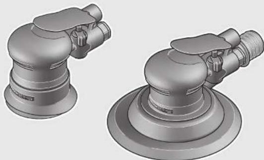
Product Features
The numbering of the product features refers to the illustration of the pneumatic tool on the graphics page.
1 On/Off switch
2 Air outlet with silencer
3 Connection socket at air intake
4 Hose fitting.
5 Speed regulator
6 Extraction hood
7 Open-end spanner (21 mm)
8 Washer
9 Sanding plate
10 Sanding sheet
11 Dust extraction
12 Clutch
13 Hose clamp
14 Supply-air hose
15 Exhaust-air hose
- Accessories shown or described are not part of the standard delivery scope of the product. A complete overview of accessories can be found in our accessories program.


Technical Data
Noise/Vibration Information
| Pneumatic Random Orbit Sander | ||||
| Article number 0 607 350 ... | ... 198 | ... 199 | ... 200 | |
| No-load speed n0 | min-1 | 12000 | 12000 | 12000 |
| Stroke | mm 2.5 | 5.0 | 2.5 | |
| Sanding sheetø | mm 80 | 150 | 150 | |
| Max. working pressure for tool | bar | 6.3 | 6.3 | 6.3 |
| psi | 91 | 91 | 91 | |
| Thread size of hose connection | 1/4" NPT | 1/4" NPT | 1/4" NPT | |
| Inner diameter of hose | mm 10 | 10 | 10 | |
| Air consumption at no-load | l/s | 8.3 | 8.5 | 8.5 |
| cfm | 17.6 | 18.0 | 18.0 | |
| Weight according to EPTA-Procedure 01:2014 | kg | 0,62 | 0,68 | 0,72 |
| lbs | 1,3 | 1,5 | 1,5 | |
Sound emission values determined according to EN ISO 15744. The noise level when working can exceed 80 dB(A). Wear hearing protection!
| Typically the A-weighted noise level of the pneumatic tool is: | ||||
| Sound pressure level LpA | dB(A) | 73 | 76 | 76 |
| Uncertainty K | dB | 3 | 3 | 3 |
| Vibration total values ah (triax vector sum) and uncertainty K determined according to EN 28927: | ||||
| ah | m/s2 | < 2.5 | 3.1 | 3.1 |
| K | m/s2 | 1.5 | 1.5 | 1.5 |
The vibration emission level given in this information sheet has been measured in accordance with a standardised test given in EN ISO 11148 and may be used to compare one pneumatic tool with another. It may be used for a preliminary assessment of exposure.
The declared vibration emission level represents the main applications of the pneumatic tool. However if the pneumatic tool is used for different applications, with different accessories or insertion tools or is poorly maintained, the vibration emission may differ. This may significantly increase the exposure level over the total working period.
An exact estimation of the level of exposure to vibration should also take into account the times when the pneumatic tool is switched off or when it is running but not actually doing the job. This may significantly reduce the exposure level over the total working period.
Identify additional safety measures to protect the operator from the effects of vibration such as: maintaining the pneumatic tool and the accessories, keeping the hands warm, organisation of work patterns.
Declaration of Conformity
C
We declare under our sole responsibility that the product described under "Technical data" complies with all applicable provisions of the directive 2006/42/EC including its amendments and is in conformity with the following standards: EN ISO 11148-8.
Technical file (2006/42/EC) at: Robert Bosch Power Tools GmbH, PT/ECS, 70538 Stuttgart, GERMANY
Henk Becker
Executive Vice President
Engineering
Helmut Heinzelmann
Head of Product Certification
PT/ECS

m = 32
Robert Bosch Power Tools GmbH 70538 Stuttgart, GERMANY Stuttgart, 01.01.2017
Assembly
Connecting the Air Supply (see figureA)
- Ensure that the air pressure is not lower than 6.3 bar (91 psi) because the pneumatic tool is designed for this operating pressure.
For maximum performance, the values for the inner hose diameter as well as the connection threads must be adhered to as listed in the "Technical Data" Table. To maintain the full performance, only use hoses with a maximum length of 4m . The compressed air supplied should be free of foreign material and moisture to protect the tool from damage, contamination, and the formation of rust.
Note: The use of a compressed-air maintenance unit is necessary. This ensures proper function of the pneumatic tools.
Observe the operating instructions of the maintenance unit. All fittings, connecting lines and hoses must be dimensioned for the pressure and the required air volume.
18|English
Avoid restrictions in the air supply, e.g., from pinching, kinking, or stretching!
When in doubt, check the pressure at the air inlet with a pressure gauge with the pneumatic tool switched on.
Connecting the Air Supply to the Pneumatic Tool
- Screw hose fitting 4 into the connection socket at air inlet 3.
To avoid damage to interior valve components of the pneumatic tool when screwing hose fitting 4 in or out, it is recommended to counter-hold the projecting connection socket of air intake 3 with an open-end wrench (size 19mm ). - Place the supply-air hose 14 with the appropriate clutch 12 onto the hose fitting 4.
Note: Always mount the supply-air hose to the pneumatic tool first, then to the maintenance unit.
Exhaust-air Guidance (seefigure B)
With exhaust-air guidance, the exhaust air can be diverted through an exhaust-air hose away from your workplace, while at the same time achieving optimal sound-proofing. Additionally, your working conditions are improved, as your workplace can no longer be contaminated though oil-containing air and dispersed dust or chips.
- Unscrew the silencer at air outlet 2 and replace it with a hose fitting 4.
- Loosen hose clamp 13 of the exhaust-air hose 15, mount the exhaust-air hose to hose fitting 4 and retighten the hose clamp.
Changing the Tool
Use only flawless tool bits that are not worn. Defective tool bits can break, for example, and cause injury or damage.
Replacing the Sanding Sheet
- When attaching a new sanding sheet, remove any dust or debris from the sanding plate 9, e. g., with a brush.
The surface of the sanding plate 9 is fitted with Velcro backing for quick and easy fastening of sanding sheets with Velcro adhesion.
- Press the sanding sheet 10 firmly against the bottom side of the sanding plate 9.
0607 350 199]...200:Make sure that the punched holes in the sanding sheet are directly over the holes in the sanding plate to ensure optimum dust extraction.
Selecting the Sanding Sheet
Depending on the material to be worked and the required rate of material removal, different sanding sheets are available:
| Material Application Grain size | |||
| bestPaint | - Paint - Varnish - Filling compound - Filler | For sanding off paint | coarse 40 60 |
| For sanding primer (e. g., for removing brush dashes, drops of paint and paint run) | medium 80 100 120 | ||
| For final sanding of primers before coating | fine 180 240 320 400 | ||
| expertWood | Expert for Wood - All wooden materials (e. g., hardwood, softwood, chipboard, building board) | For coarse-sanding, e. g. of rough, unplanned beams and boards | coarse 40 60 |
| For face sanding and planing small irregularities | medium 80 100 120 | ||
| Best for Wood - Hard wood - Particle Board - Building board - Metal materials | For finish and fine sanding of wood | fine 180 240 320 400 | |


English | 19
| Material Application | Grain size | ||
| - Automotive paint | For pre-sanding | coarse 80 | |
| - Masonry, stone | For shaping and braking edges | medium 100 | |
| - Marble | 120 | ||
| - Granite | For final sanding and forming | fine 180 | |
| - Ceramic | 240 | ||
| - Glass | 320 | ||
| - Plexiglas | 400 | ||
| - Glass-fibreplastics | For polish-sanding and rounding off edges | very fine 600 | |
| 1200 | |||
Selection of the Sanding Plate
The pneumatic tool can be equipped with sanding plates of different hardness depending on the application:
- Sanding plate, extra soft: Suitable for polishing and sensitive sanding, incl. on convex surfaces.
- Soft sanding plate: Suitable for all sanding applications and general-purpose use.
- Hard sanding plate: Suitable for high sanding capacity on flat surfaces.
Replacing the Sanding Plate
Note: Replace a damaged sanding plate 9 immediately.
- Pull off the sanding sheet 10.
- Slide the open-end spanner 7 under the height-adjustable extraction hood 6 and hold the grinder spindle in place with the open-end spanner.
Turn the sanding plate 9 counterclockwise from the grind er spindle. Remove the washer 8, place it on the new sand ing plate and turn the plate on again clockwise with the washer.
0607 350 199|...200:The second washer 8 can be used additionally so that the random orbit sander does not adhere to the workpiece when the dust extraction is activated.
Dust/Chip Extraction
Dusts from materials such as lead-containing coatings, some wood types, minerals and metal can be harmful to one's health. Touching or breathing-in the dusts can cause allergic reactions and/or lead to respiratory infections of the user or bystanders.
Certain dusts, such as oak or beech dust, are considered as carcinogenic, especially in connection with wood-treatment additives (chromate, wood preservative). Materials containing asbestos may only be worked by specialists.
- As far as possible, use a dust extraction system suitable for the material.
- Provide for good ventilation of the working place.
- It is recommended to wear a P2 filter-class respirator.
Observe the relevant regulations in your country for the materials to be worked.
Prevent dust accumulation at the workplace. Dusts can easily ignite.
Sanding without dust extraction (0 607 350 198)
- Use sanding sheets with no holes.
External Dust Extraction (0 607 350 199|... 200)
- Connect the extraction hose (accessory) directly to the dust extraction 11.
The vacuum cleaner must be suitable for the material being worked.
When vacuuming dry dust that is especially detrimental to health or carcinogenic, use a special vacuum cleaner.
Operation
Starting Operation
The pneumatic tool works optimally at a working pressure of 6.3 bar (91 psi), measured at the air inlet when the pneumatic tool is switched on.
- Remove application tools before you start operating the pneumatic tool. An application tool which is left attached to a rotating part of the power tool may result in injury.
Note: If the pneumatic tool does not start, e.g. after an extended period of rest, interrupt the air supply and turn the sanding plate 9 repeatedly. This will eliminate adhesive forces.
To save energy, only switch the pneumatic tool on when you are using it.
- To switch on the pneumatic tool, press the on/off switch 1 down and keep it pressed during operation.
- To switch off the pneumatic tool, release the On/Off switch 1.
Preselecting the Speed (see figure C)
With the speed regulator 5 you can preselect the required speed also during operation.

- For maximum speed, slide the speed regulator 5 away from the connection socket 3.

- For minimum speed, slide the speed regulator 5 towards the connection socket 3.
The required speed depends on the material and the working conditions and can be determined through practical testing.


20|English
Working Advice
Always wait until the pneumatic tool has come to a complete stop before placing it down.
Make sure that self-adhesive sanding sheets are fitted concentrically on the sanding plate.
In case of an interruption of the air supply or reduced operating pressure, switch the pneumatic tool off. Check the operating pressure and start again when the operating pressure is optimal.
Sudden loads cause a sharp drop in speed or a complete stop, yet do not cause damage to the motor.
Sanding Surfaces
- Switch the pneumatic tool on, place the entire sanding surface on the surface to be sanded and move it over the workpiece with moderate pressure.
The material removal rate and sanding result are primarily determined by the choice of sanding sheet, the pre-selected speed and the contact pressure.
Only immaculate sanding sheets will deliver good sanding performance and protect the pneumatic tool.
Pay attention to apply uniform sanding pressure; this increases the working life of the sanding sheets.
Excessively increasing the contact pressure will not lead to increased sanding performance, rather it will cause more severe wear of the pneumatic tool and of the sanding sheet.
A sanding sheet that has been used for metal should not be used for other materials.
Use only original Bosch sanding accessories.
Rough Sanding
- Attach a sanding sheet with coarse grain.
- Apply only light pressure to the pneumatic tool so that it runs at higher speed and a higher material removal rate is achieved.
Fine Sanding
- Attach a sanding sheet with fine grain.
- Move the pneumatic tool with moderate pressure flat on the workpiece in a circular motion or alternately along and across it. Do not tilt the pneumatic tool in order to avoid sanding through the workpiece, e.g. veneers.
You can reduce the sanding plate speed by lightly varying the contact pressure or changing the speed, although the random orbit motion is retained.
- Switch the pneumatic tool off after completing operation.
Maintenance and Service
Maintenance and Cleaning
Have maintenance and repair work carried out only through qualified persons. This will ensure that the safety of the pneumatic tool is maintained.
Regularly measure the no-load speed of the grinder spindle. If the measured value of the specified no-load speed exceeds _0 (see "Technical Data"), you should have the pneumatic tool checked at a Bosch after-sales centre. If the no-load speed is too high, the application
tool can break; if the speed is too low, the performance decreases.
An authorized Bosch after-sales service agent will carry out this work quickly and reliably.
Use only original Bosch spare parts.
Regular Cleaning
- Clean the sieve at the air intake of the pneumatic tool regularly. For this, unscrew the hose fitting 4 and remove any dust and debris from the sieve. Afterwards, retighten the hose fitting again.
Water and debris particles in the compressed air cause rust and lead to wear of plates, valves etc. To prevent this, fill several drops of engine oil into the air intake 3. Reconnect the pneumatic tool to the air supply (see "Connecting the Air Supply", page 17) and run it for 5-10 seconds, while catching/picking up the escaping oil with a cloth. Always carry out this procedure when not using the pneumatic tool for a longer period of time.
Scheduled Maintenance
Clean the gearbox after the first 150 running hours using a mild solvent. Follow the solvent manufacturers directions for use and disposal. Lubricate the gearbox using Bosch gearbox lube. Repeat the lubrication procedure every 300 hours after the initial gearbox service.
Special gearbox grease (225 ml)
Article number 3605430009
- The motor plates should be checked regularly by specialised personnel and replaced, if required.
Lubrication of Pneumatic Tools that do not belong to the CLEAN Product Line
For all Bosch pneumatic tools that do not belong to the CLEAN product line (these have a special type of compressed-air motor that functions with oil-free compressed air), oil mist should be added continuously to the flowing-through compressed air. The compressed-air oiler required for this is included in the compressed-air service unit on the line side of the pneumatic tool (for more details, please refer to the compressor manufacturer).
For direct lubrication of the pneumatic tool or admixtures to the service unit, use SAE 10 or SAE 20 engine oil.
Accessories
For more information on the complete quality accessories program, please refer to the Internet under www.bosch-pt.com or contact your specialist shop.
After-sales Service and Application Service
In all correspondence and spare parts orders, please always include the 10-digit article number given on the type plate of the pneumatic tool.
Our after-sales service responds to your questions concerning maintenance and repair of your product as well as spare parts. Exploded views and information on spare parts can also be found under:
www.bosch-pt.com
Français|21
Bosch's application service team will gladly answer questions concerning our products and their accessories.
Great Britain
Robert Bosch Ltd. (B.S.C.)
P.O.Box 98
Broadwater Park
North Orbital Road
Denham
Uxbridge
UB95HJ
At www.bosch-pt.co.uk you can order spare parts or arrange
the collection of a product in need of servicing or repair.
Tel. Service: (0844) 7360109
E-Mail: boschservicecentre@bosch.com
Ireland
Origo Ltd.
Unit 23 Magna Drive
Magna Business Park
City West
Dublin 24
Tel. Service: (01) 4666700
Fax: (01) 4666888
Australia, New Zealand and Pacific Islands
Robert Bosch Australia Pty. Ltd.
Power Tools
Locked Bag 66
Clayton South VIC 3169
Customer Contact Center
Inside Australia:
Phone: (01300) 307044
Fax: (01300) 307045
Inside New Zealand:
Phone: (0800) 543353
Fax: (0800) 428
Outside AU and NZ:
Phone: +61 3 95415555
www.bosch.com.au
Republic of South Africa
Customer service
Hotline: (011) 6519600
Gauteng - BSC Service Centre
35 Roper Street, New Centre
Johannesburg
Tel.: (011) 4939375
Fax: (011) 4930126
E-Mail: bsctools@icon.co.za
KZN - BSC Service Centre
Unit E, Almar Centre
143 Crompton Street
Pinetown
Tel.: (031) 7012120
Fax: (031) 7012446
E-Mail: bsc.dur@za.bosch.com
Western Cape - BSC Service Centre
Democracy Way, Prosperity Park
Milnerton
Tel.: (021) 5512577
Fax: (021) 5513223
E-Mail: bsc@zsd.co.za
Bosch Headquarters
Midrand, Gauteng
Tel.: (011) 6519600
Fax: (011) 6519880
E-Mail: rbsa-hq.pts@za.bosch.com
Disposal
The pneumatic tool, accessories and packaging should be sorted for environmental-friendly recycling.
Observe all applicable environmental regulations when disposing of old grease and solvents.
Dispose of motor plates according to regulations! Motor plates contain Teflon. Do not heat them beyond 400^ , otherwise vapours hazardous to one's health can develop.
If your pneumatic tool can no longer be used, deliver it to a recycling centre or return it to a dealer - for example, an authorized Bosch after-sales service agent.
Subject to change without notice.
Français
Executive Vice President
Engineering
Helmut Heinzelmann
Head of Product Certification
PT/ECS

i. v.k = w .
Robert Bosch Power Tools GmbH
70538 Stuttgart,GERMANY
Stuttgart, 01.01.2017
\section*{Caracteristiques techniques}
Robert Bosch (France) S.A.S.
Executive Vice President Engineering
Helmut Heinzelmann
Head of Product Certification PT/ECS

Robert Bosch Power Tools GmbH
70538 Stuttgart,GERMANY
Stuttgart, 01.01.2017
Datos téncicos
Henk Becker Helmut Heinzelmann
Executive Vice President Head of Product Certification
Engineering PT/ECS

Robert Bosch Power Tools GmbH
70538 Stuttgart, GERMANY
Stuttgart, 01.01.2017
Montagem
Fascicolo technician (2006/42/CE) presso:
Robert Bosch Power Tools GmbH, PT/ECS, 70538 Stuttgart, GERMANY
Henk Becker Helmut Heinzelmann
Executive Vice President Head of Product Certification
Engineering PT/ECS
f( 2) = h - u1
Robert Bosch Power Tools GmbH
70538 Stuttgart, GERMANY
Stuttgart, 01.01.2017
Montaggio
Executive Vice President
Engineering
Helmut Heinzelmann
Head of Product Certification
PT/ECS

Robert Bosch Power Tools GmbH
70538 Stuttgart,GERMANY
Stuttgart, 01.01.2017
Technische gegevens
Executive Vice President Engineering
Helmut Heinzelmann
Head of Product Certification PT/ECS

Robert Bosch Power Tools GmbH
70538 Stuttgart,GERMANY
Stuttgart, 01.01.2017
Montering
Tilslutting til luftforsyningen (se Fig. A)
Bosch Service Center
Telegrafvej 3
2750 Ballerup
Pá www.bosch-pt.dk k an der online bestilles resededele erer oprettes en reparations ordre.
TIf. Service Center: 44898855
Fax: 44898755
E-Mail: vaerktoej@dk.bosch.com
Bortskaffelse
Unified National Fine Thread Series)

Whitworth-ganga

National pipe thread
Executive Vice President Engineering
Helmut Heinzelmann
Head of Product Certification PT/ECS

i. V. h = u_c
Robert Bosch Power Tools GmbH
70538 Stuttgart,GERMANY
Stuttgart, 01.01.2017


Svenska 73
Montage
Bosch Service Center
Telegrafvej 3
2750 Ballerup
Danmark
Tel.: (08) 7501820 (inom Sverige)
Fax: (011) 187691
Avfallshantering
Executive Vice President
Engineering
Helmut Heinzelmann
Head of Product Certification
PT/ECS
kn i = 1^na_in^i - 1
Robert Bosch Power Tools GmbH
70538 Stuttgart,GERMANY
Stuttgart, 01.01.2017
80|Norsk
Montering
Executive Vice President
Engineering
Helmut Heinzelmann
Head of Product Certification
PT/ECS

Robert Bosch Power Tools GmbH
70538 Stuttgart, GE
Stuttgart, 01.01.2017
Asennus
Henk Becker
Executive Vice President
Engineering
Helmut Heinzelmann
Head of Product Certification
PT/ECS

Robert Bosch Power Tools GmbH 70538 Stuttgart,GERMANY Stuttgart,01.01.2017
Texvika xapaaktnpioiuka
Euvtnponk kal Service
Suvtnpnonkakαaipiaoic
Na avaTeTc epyoic ouvtnponk kal emokueh npovoe apotaeknalecupevo npoowuK. Eto EaopaA Lietai diatnpon nca opaaleia tou epyaieiou aeoc.
Metpate TAKtKa Tc Ovoaotike cTPOpeC Tou eOVAe avoC.Eav neptnpevTu npBipoketai naw ano nv kaTaxwnpnevTuiv Ovoaotukov Otpoovn (Bene «Texvika Toxieia),npenla vavaoeceTou eAeyxo Tou epyaleiou nmeqevou aepa o eva Kevtpo oepicTc Bosch.1e nepimwn evoc nou uynlou apioou ovopatikov atpovmupoei va anaoi to eapntma,oe evanoluxaunAo apioo atpovmupoei vevetain anodoo npayac.
'Eva eouao6o7nuevo katoanpa Service nC Bosch ekTeAelTc epyaoc autc ypnoopa ka aopaaoc.
Na xnpaonoiieite anokleiotik yvnoia avtalaktka ano Tnv Bosch.
TuktkocKaBapiao
Na kaBapiciTe taktka to naeyma otnv eio do aepoc tou epyaleiou aepoc. I' auto npenei va Eeibiodote pakop oawlya 4 kalva apaipoeetra owariidia okovnc kalpwouidano to naeyma.Akoolouwoc npenei va biiodoete nla KaAto pakop awhya.
-Ta oaiatia vepou kai bpwiaacnou nepiexovt aotov aepa npokalouv oleidoeic kai onyouv oe φopata waauadav,baibowk. Tia va emnoiaete kati tetoio penei va balete otny eioo aepoc 3epikec otayovec laoiu kvnTpa. Uuvdeote nai to epayaleio aepoc otnpoxh aepoc (Bene «Uvcon otny tropoosoaia aepoc), olaiba 95) Ka aphtote to va leitoupyae1 5-10 s. Zpouyilte tautoxpo

98|Türkce
va to eepxoyoevo lao eva navi. 2e nepinwnou to epyaleio aepoc dev npoketai xnpaonoinei yia apketok Kaipo, tote npenei va eapopcete navtoe tv npanaVw diaikaoia.
Tepiodikouvtipn
KaaploTe o npxavioo metaboong kvnoc met ao tic npwtec 150 wpcce aeioupyiaic evav nio diautn. Tnpote tic oxetikc me tn xphon kal anoupon tou diautn umoeiEiec tokataakeuaotn tou.Akoloobwc aabowote to npxaviOo metaboang kvnoc me to ebiok yia npxaviouoc kvnanc linoc ts Bosch. Na enavaaete tvnapanawdiabla kaolakatapiaouo peta ano 300 wpcce aeioupyiae metavot npto kaqapiao.
EioKIOIIOcYiaunxavioouc kivnOc (225 ml) Apoocupertnpou 3605430009
Ta eaojata Tou kivtnpia penei va eeyovta oe taktikxovika diaonata ano eikka eknaideeuevo npoomegako Ka, av xpeiaotei, va aalazovta.
Ainavon twv epyaleiw nemeoeevou aepa nov dev avn KOUV OTNV KATAOKEUAOTIK oipd CLEAN
Se ola ta epyaleiaepeoc nC Bosch nou dev avnkov an katakeuaotkih oeipc CLEAN (evac ciikk ckvntnpac eepoc nau letoupyel me aepa xwlplc ad) 0a npenei va npoetete diapok cva vepoc laiou stov peovta aepa. To anapalntno y au to laobwnpiaepoc pbioketai onn mova dbnponnc apoc nou eliva uovdejev n ev epia je to epyaleio aepoc (neipaootepec oxetukc npanpoopiec thnapete an tov katookeaatou ouptieon).
Na xpaonpoieire lai kivtnpaa SAE 10 n SAE 20 yia va lamve to epyaleio aepoc aepoa n ia npoepen otn povda ouvtponnc.
Egaptjmuata
To nApeoypapa ma eapntmuatw nootntac o to Bpeite otnyn Aektpovikni diuoyvwn www.bosch-pt.com n otov apuo- bio yia aoc ciko eumopa.
Service kalapoxn oupouov xpionc
Otav zntate nnpoopoeic kaooc kai otav npayvevete avtalakata napakaloue va avapepete onwohnoto 10-psiapo tepetnpiou nou avapepetai otny nivakiia kataaekuaotn Tou epyaleiou aepoc.
To Service anavrta otic epwtnoeic oac oxytka me tny eniokeun kalntouvtponan tou npoiovoc aoc kaowc yia ta katalaanaa avtaalaktkia:
www.bosch-pt.com
H ouda napoxic ouuouawv nC Bosch anavta euxapiotw otic epwtnoeocacxetikae ta npoiovta mac kal a vtaa- kTtka Touc.
EAAa
Robert Bosch A.E.
Eoxelac 37
19400Kopwnl-Aθηγα
Tel.: 2105701270
Fax: 2105701283
www.bosch.com
www.bosch-pt.gr
ABZ Service A.E.
Tel.: 210 5701380
Fax: 2105701607
Anoupon
Ta epyaIeia aepoc, Ta eApntmuata kai ouakueoic npenei va avakukawovtai pe TpOIO piko npoc To nepiBaaov.
Na anooopete Ta uka iinavoc kai kaqapoiou pe tpo no pfuk npoc to nepiaalov. Na aauabave unoyn oac tic oxetukc voukc diataeic.
Na anoopete kavovika Ta eaojata Tou kivtnopa! Ta eaojata Tou kivtnpa nepieoxu Teflon. Mny ta cepaave nepiaotepo ao 400^ diaopocetik maopei va p ynOouv avuyieivec avaouidoeic.
O'Atv To epyaIeio aepoc axpnoTeutei, npene va poookoHotei oe eva keVtro avakkawc uAikwv naEITpaepol oTo einopio n e eva eoouoiobotnevo kataonma Service tC Bosch.
Tnpoue to 6ikaiwa aalayov.
Türkce
Güvenlik Talimatu
Haval Aletler icin Genel Güvenlik Talimatu
4UYARI
Montaj, isletme, onarim, bakim, aksesuar deigistirme islerine ve haval aletinin yaki
Executive Vice President Engineering
Helmut Heinzelmann
Head of Product Certification PT/ECS

Robert Bosch Power Tools GmbH
70538 Stuttgart, GERMANY
Stuttgart, 01.01.2017
Montaj
Hava ikmalinin baglanmasi (Bakiniz: Sekil A)
Basincli havanin 6,3 bar (91 psi) altinda olmamasina dikkat edin,cunku havali alet bu isletme basincina gore tasarlanmistir.
Bosch San. ve Tic. A.S.
Ahi Evran Cad. No:1 Kat:22
Polaris Plaza
80670 Maslak/Istanbul
Bosch Uzman Ekibi +90 (0212) 367 18 88
Isiklar LTD. STI.
Kizilay Cad. No: 16/C Seyhan
Adana
Tel.: 0322 3599710
Tel.: 0322 3591379
Executive Vice President Engineering
Helmut Heinzelmann
Head of Product Certification PT/ECS

Robert Bosch Power Tools GmbH
70538 Stuttgart,GERMANY
Stuttgart,01.01.2017
Dane techniczne
Executive Vice President
Engineering
Helmut Heinzelmann
Head of Product Certification
PT/ECS

Robert Bosch Power Tools GmbH
70538 Stuttgart,GERMANY
Stuttgart, 01.01.2017
118| Cesky
Technická data
Bosch Service Center PT
K Vapence 1621/16
692 01 Mikulov
Na www.bosch-pt.cz si muzete objednat oprava Vaseho stroje online.
Tel.: 519305700
Fax: 519305705
E-Mail: servis.naradi@cz.bosch.com
www.bosch.cz
Zpracovani odpadu
Pneumaticke na radi, prislusenstvi a obaly by mely byt dodany k opetovnemu zhodnoceni neposkozujicmu zivotni prostre di.
Executive Vice President Engineering
Head of Product Certification PT/ECS

Robert Bosch Power Tools GmbH
70538 Stuttgart,GERMANY
Stuttgart, 01.01.2017
Montáz
Henk Becker
Executive Vice President
Engineering
Helmut Heinzelmann
Head of Product Certification
PT/ECS
kn//x 且 kn > 1 �恒成立
Robert Bosch Power Tools GmbH 70538 Stuttgart,GERMANY Stuttgart,01.01.2017
Összeszerelés
Be3oNaChOcTb Ha pa6ooyem MecTe
CneHte 3a NOBepxHOCTHM, KOTOpbIE BCNEcTBHe HcN0JIb3OBAHHHNCTPyMeHTaMOrY CTaTb CCKoJIb3KHMn,a TAKKe IpeDToBpaAaHte OAnCHOCTb CNOTbKaHHo NHEBMATHueCKHe HnI rIpaBnueCKHe UHaTHn. NockaJIb3bIBaHHe, CNoTbKaHHe nIpaHHe ABJIOTCr OCHOBHbIMn pInuHAMn TpABM Ha paBOeM MeCTe.
He pa6oTaIe C nHEBMaTHueckHM HhCTpyMeHOM BO B3pBbBOONACHOpeE, B K TOPOJI HxOaDcTc RopU- HE XHKOcTHn, Ra3bl NnN PbIbI. PnO pb6oTKe o6pa6aTbIbAeMOI 3a0rTOBKNMOrY O6p3a0bIBaTcNCKpbIOTOKOpBX B03MOXHO BC0nJaMeHENe Nbln NnPiAPOB.
Pn pa6ote c nHEBMATHueeCKM HHTCPyMeHOM He NOIpyKaTe Kpa6oey MeCTy 3pHTenE, Detet H nocTeHTeN. Ecn Bac OTBNEKyt NocTOPOHHne, Bb MOxTe NOTepaTb KOHTpOb HAD INHEBMATHueeCKM HHTCPyMeHOM.
TexHka 6e3oNaChOCTn npnaPbOte c nHeBMaTHueCKMMN HcTpyMeHTaM
HnKOrda He HnPaBnIte NotoK Bo3dyXHa Ce6n Hpyrnx IIOe H He HnPaBnIte XoNODhBn BO3dyX Ha pyKn.CxAtbI B03dyX MoKeT PnIBecTH K cepBe3HbIM TpaBMam.
PpOBepeIe coeHHHeH Hnnn HnTahna. Bce y3nbTexo6cnyKbAHnMyfBtHn HuaHn DoJnxbl 6bItb paCunTahbHa daBnHeH n o6bem Bo3dyxa, yka3aHbHe B TexHNuecknx DaHHbx.CnHxKom Hn3Koe daBneHne OtnpaTeNbHO cKa3bBaetcHa fHyKuHOaHbHo CnOco6HocTHNHEBMONHCTpyMeHTA, CnHxKom 60nlbWoe daBneHne MoXet HaecTN MaTePnaHbHy uep6 n npBecTN K TpaMam.
3aunuaine 7nnaHnOT n3r6a, cyxhen, pactbopnten HoctpbxkpaEB.3auuuaite uhaHHn OT tenna, MaCna hbaaaouxxcn detanei. HeMeDneHO MeHnE NOBpeXdHnh bnaHr. NOBpeXdHeN IINHn IITAHN MOKeT npBeCTN K 6neHIO INHEMaTHueCKO rIaHa r TpaBMam. NpHrtar nbInh cTpyKka MOrY nOpAHNb rna3a.
Cneinte3aTEM,HTo6bI 3axHMnIg IuaHra Bcerda6bn Xopo0o 3aTAYr. BcneCTBnE PNOXO3aTAKKINN NOBpeKHeHn3axHMOBIIaIHaRbO3MOKeH HeKOHTPONiPOBaHHb BixOqBO3dyxa.

Pycckn139
Be3oNaChocThIIODei
Bybte BHNMaTeNbHbI, cneHe 3a TeM, yTo BbI denaeTe, npoDymHaNo noXoHnTe K paOte C nHEBMATHeCKMN HNCTPymeHOM. He paOtaIte C nHEBMATHeCKMN HNCTPymeHOM B yCTaIOM COCTOHHN HN ECNNBbI HaxoHnTEcb NOD BnHHmE NapKOTKHOB, CNHPTHbIX HAHTNKOB HNNEKapCTB. MHyTHaRE HEBHMaTeNbHOCTb npn paOte C nHEBMaTHueckm HNCTpymeHOM MOKeT npNBecTN K cepBe3HbIM TpaBMam.
OeBaTe pa6oyo oexny no63aTeNbHO hadeBaIte 3auHTbIe ouKn. HnBnaybHbIe cpeCTBa 3auNTbI, TaKae Kc 3auNTa OprAHOB DbIXaHIN, 3auNTHaHECKOJIb 3aUaJyOBb, 3auNTHaJ KAcKa NnH HayuHKn, -B 3aBN CmOCTN OT HnCTpykun pa6oTaTeNn Tpe6oBaHn TEXHHK6e3oNaChOCTn HnCaHnTapHbIX HopM -CHXkaOT PnCK TpABM.
H36eraTe HnpeDnHapeHnO RKnIOueHn. NpeTe TEM, KAK NOKNIIOHTb INBEmATNueCKn HNCTpyMeT K TOCHNYK BO3dyxa, NOHNTb NIN NpeHeCt erO, y6eHNTecb B TOM, YTO INBEMATNueCKN HNCTpyMeT BblKIOUeH. NpeHOCKa NHEBMATNueCKOr HNCTpyMeTa C NaIbCeMa HBaIKIOUATEne NIN NOKNIIOUEHNE BKNIOUeHHo TNO INBEMATNueCKOr HNCTpyMeTA K HNCTOUHky BO3dyxa MORYT PnHBECrN K HeCuaCTbHM CnyaAM.
Ipeed BkIOueHHeM INHEBMATNueCKOrHO HCTpyMeHTa y6epHTe HAcTPOeHbIe HHCTpyMeHTb.HAcTPOeHbI HnCTpyMeHT, HaxOJaUncB BO BpaAioUeCn DeTann INHEBMATNueCKOrHO HCTpyMeHTa,MOKET CTaTB pINuHOB TpaBMbl.
He nepeoehuBaItece6B.Bcerda3aHMaIteyctoiyHBOE NOIOXEHNE COXPAHHTe paBHOBecne.YcOnuHBOE NOIOXEHNE I COOTBeTCTByIOUeI NOIOXEHNE TenaIO3BOJAT BamNyUe coXPaHbKoHTpOJIb HAD INHEBMTuueCKHM HCHPTyMEHOT B HEOKDaHHbIX CITyaUNX.
HocHTe noxOaIyO oExdy. He hocHTe npocTophyO odexdy H yKpaWeHH. DePckhte BOnocbl, odexdy H pyKabNbI Ha pacCToHHN OT BpaaiouXcraTeanE. IpocTOpHa OExka, yKpaWeHH N dInHHbIe BOnocbl MoRyt Nonactb Bo BpaaioUHeCraTeaII.
Ecn npedycmptepaBo3MOXHOCTbMOHTaxa yctpoCTB DnAOTcCObHc60paNbHH,npOBepTe npaBnHbHOCTbHX NOKNIPOeHH NcNoJIb3OBAHH. cNOIb3OBAHH TAKNXyCTpoCTB COKPaAaETPCK BO3HNHOBEHHOnaCHbIX CHTyaUN H3-3a PbHN.
He BbixaIte Hapmyo Otpa6oTaHHb BO3dyx. N36eraTe nonadHnO Otpa6oTaHHo BO3dyxa BRna3a. Otpa6oTaHHb BO3dyx, BbxOJaUH N3 INHEBMATuecKOrOHCTpyMeHTa, MoKeT COepKaTb BOy, MaCIO, MetaJIHueCKHe YactuKN H 3arpa3HeHHN H3 KOMnPecccopa. 3To UpeBaTO yIep6om nIra 3IopOBbI.
PpabHbHoe 6paueHHe c nHEBMaTHueckHM HnCTpyMeH TOM HeroHCNoB3OBAHHe
NcnoB3yIte 3aXHMhIe yctPoHCTBa HnTHCkN DnA 3akpenenHHn NIOIpOpKn Oba6aTbIbAemOro MaTe pHa. PnpdepkxNBaOcbpaTaIBaEMyIO DeTanb pyKoi nnn npKmam ee K Tely, HeIb3o oBeceNeHTb 6e0Na- CHOCTb PnPaBoTe C NHeBMAtuYeCKM INHCTpyMeHToM.
He neperpykaTe nHEBMATHueckn HNCTpymENT. NcNoIb3yIe nHEBMATHueckn HNCTpymENT, KOTOpBINcEuaNbHO npEHa3Hauen dA BaWero Bua da pa6oT. IOnxOJaI INHEBMATHueckn HNCTpymENT pa6oTaET NyUwe I HaedKHee By yKa3aHHOM dIra Hero dInaNa3oHe MOuHOCTH.
He hcnb3yIte nHEBMATHueckn HNCTpyMeT C NOBpeXeHHbIM BbIKIOaTeIeM. IHeBMATHueckn HNCTpyMeT, KOTOpbI He BkIOuAeTCr NIN He BbIKIOUaETcR, onaceH Tpe6yeT pEmoHTa.
OTKIOUaIte Noauy Bo3Dyxa NepeH NactpoKoi HNCTpyMeHTa, 3aMeHO npHaJnxHOcte Hnnc EcnB BbI DOnrOe Bpem He 6yTe ero hCnObl30BaTb. 3Ta Mepa IpeIOCTOpOXHcTn PpeIOTBpaUaETHepeHaMepeHHe BKNIOUeHHe INHEBMATueCKOrO HNCTpyMeHTa.
XpaHHTe HEnCNoB3yEmbIe INHeBMaTHueCKne HnCTpyMeHTbI B HeoctynHom DnA DeTeMce. He pa3peMaTte NOnB3OBaTbCn INHeBMaTHueCKm HnCTpyMeHToMnUcAm, KOTOpBle He 3HaKOMbIC Hm Hm HnHTaAMHactounx HnCTpyKuN. INHeBMaTHueCKne HnCTpyMeHTbI ONaCHbI B pyKaX HeoNtBHy XnL.
TuaTeNbHO yXaXHbAte 3a NHeBMaTHuecKm HnCTpyMeHTOM.CneIeTE 3a TeM, YTO6bI NOBHXKbIe TaeTNIHCTpyMeHTa paOtaTI HcnpBaHO He 3aedAnH YTO6bI DeTANI,KOTOpBE Moryr BnHrTa Ha paOby NHeBA mTHueckOro HnCTpyMeHTa, He bSIHN CnOMaHIbI HNNOBpexDeHJI. NepED NcONb3OBaHHem NHeBMaTHueckOro HnCTpyMeHTa NobPexDeHHBe Detani Heo6xOJHMO OTPeMoHTPiPoBaTb.MHOxECTBO HeCuaCTbIX CnyuaeBNPOINCKOJIT No NPnHHe NIOXOTo yXoJa 3a NHeBMaTHueckKIM HnCTpyMeHTOM.
McnoB3yTe NHEBMATHueckm HnCTpyMeHT, npHHaNexKHOCTKN Hemy, CMeHHbIe paOoune HnCTpyMeHTbI N. D. B COOTBETCTBHN C HAcTOAUM N yKa3aHNNM. YuHtBaIe TPN 3OM YCNOBn H CneUΦKy BInONHEmo pa60bI. 3TO NMOXET MAKCMaJIbHO CHIN3NTb O6pa3OBAHNE PbIMN, BN6paUNIO N yWM.
HactpaHbTa,perynnpoBaTb HcnoB3oBaTb NHeBMaTHueckne HHCTpyMeHTb pa3peWaaTc TOJbKO KbaHNΦHnnpoBaHHbIM O6yehhhim onepaTopam.
BHOCTb H3MeHHeHH BTHEBMaTHueckn HHCTpymENT 3anpeaetc. IIO6hIbe H3MeHHeHH MOYr CHN3HT bΦeKTHBHOCTb Mep NO TEXHKe 6e30NaCHOCTn NOBbICHTb PnCKdIg ONepaTopa.
CepBnC
Pemont BaIero INheBMOHCTpyMeHTa NOpyaHTe TOnbKO KBAHINHIOPOBAHHOMY NepCOAHNY TOBko C HNOJ30BaHNEM OPHNHAHBx 3AnCTeH.3TNM 06ecneuBaTc 6eOanachOCTb INHeBMOHCTpyMeHTa B DAJIbHEIWEM.
Yka3aHnnoTexHnke6e3onacHOCTnIINHEbMaTHuecknx 3KcueHTpHKOBbIX WlnΦmaunH
B cnyae nonomkn 6pa6a5b1Baem 3arotOBKN, npnHaIeXHocTH HnC amoro nHEBMATHueCKORO HNCTpyMeHTa 6bnOMKn MOrYt pa3neTaBCr C BbcOKo CKopoCTbIO.


140|Pycckn
PnKcNpyataun, aTaKxBe BoBpeMpeMOHTa, Texo6CnyXHBAHn 3aMeHb npHaJNeXHoCTe INHeBMATHecKOrO HnCTpMeHTa BcERda 063aTeNbHO HocHTnpOTnBOyDapHbte 3auNTbIe ouKn. Heo6xoHmna CTenHb 3auntbOpPeJeHReTc nKaKdOro OTdEBHorO CnyuA HCnonb3OBAHn HnCTpMeHTa KOHKpETHO.
PnBbINHeHHpaobHdTolOBHaDeBaTe3aHTHbI WEM.TakmO6pa3OM,Bam ydaCTcN36eKaTb TpaBM.
CneHTe 3a Tem, UTo6bI dpyrHe Hnca HaxOHNncb Ha 6e3oNachom pacCToHHN OT 30hbl pa60tbl. KaKdbn, KTO 3AxoND T BpaOouyIO 3OHy, DOnXeH NMeTb Ha Ce6E HNHBdYaNbHbIe CpeCTBa 3aUHTbl. O6lOMKn 3aToBKN HIN IIOJOMaHHbIX OTEp3HbIX NDCOK MOYr OTNeTeB H CTatb PnUnHOH TENEChbIX NOBpEXDeHn TaKKe H3 a npedeJaMn HeNoocpeCTBeHHo PA6Oue 30HbI.
Octopoxho!PnDINTenbHO3KcNpyataunHHBMaTHueCKoro HhCTpymeTAcmHbIpa0ouHnHCTpymeHTMOKeT HarpeBaTbC. OeBaHTe 3aunThbIne nepuAtKN.
OnepaTopn6cbnykmbauoynnepcoHAndoJXhbl6bitb B COOTBETCTBYOuEe n3NueckoF opme, Heo6xOmoMnnpa60tbC INeBMATNuueckHM HnctpyMeHTOM daHHoro pa3Mepa, BEca N MoUHOCTN.
6 BybTe rOToBBk HeoXHaHbIM DnHexHm nHeBMOHCTpyMeHTA, Bbl3BaHHbIM peAKTHBbIMn CHnAmn HnNn NtOMKo CmEHORo paOoero HHcTpymeTA. KpeKoepKHTe NHEBMaTHueckn HnCtpyMeHn npHeBeNTe KopnycH pyKn B Takoe NOnoxKeHne, pN KOtopom BblcmOxete npOTMBOEJCTBOBaT 3TN M DBHXeHHM. 3TN MEbpI ppeDOCTOPOXHOCTN NOMOYr PpeDTbPaNTb TpaBMbl.
Длpa60tbyc3THM INHEBMATHueCKHM HnCTpymENTOM npHmTE yO6HyIO No3y, cneHTe 3a CTOKHM NOOXKeHNEM Tena N H36eraIte Heyo6hBIX No3 HIN No3,B KOTopbIX CNOXHO YdepKHBaTb paBHOBecHe. PpN pOdoJIKNTHenbHOn pa6ote onepatOp dONxEH MeHbTb NOOXKeHNE Tena BO H36exKaHHe Heyo6ctBa HycTaNoCTH.
Pnnepe6oXcnoaueB03yxaHnpymeHbWeHH pa6oerydaBnEHH BblkIOHTNEHBMaTHueckn HCTpymENT. PpOBepTe pa6oee daBnEHNE IOrTB BKIOUHTe HnCTpyMeHT, KOrDa pa6oee daBnEHNE CHOBA bDeT OITTMALbHIM.
McnoB3yHToIbKO peKOMeHOBaHHbE HnPMoB Bosch cma30HbE BueCTBA.
He nnonb3yIte nobpexdenHpyo pa6oyo ochactky. KaJdbI pa3 nepeIpa60To npOBepaTe pa6oyo ochactky Ha npEpmETCKOIOB HtpeHH, aTAKKc CnIbHO ro h3Hoca.B cnyae naDEHN IHEBMATueckoro HNCTpyM enta Hn pa6oue OCHACTKN pOBepbTe Hx Ha npEpmET BO3MOXHBIX NOpEXDEHN, HCNOb3yTE ToBko HenoBpexdeHHy pa6oyu ochactky. Nocne npOBepKn MOHTaKa pa6oey OCHACTKN Bby H haxOJaUncsnoBn3OCTN IOIDONKbHbI depKAtcBHe NIOCKOCTN BpaueHHra Pa6oey OCHACTKN; BKIOUHTe JNEKTPOMHCTpymENT Ha 1 MHHTy Ha MaKChMaIbHyO qAcTOTy BpaueHH. PoBpexDeHHa pa6oay OCHACTKA, KAK IpABINO, NOMaETCB TEueHHe NTOrO p6hOHO OTPe3A BpeMeHH.
HnKorDa He NoDhOncTe pyKy K BpaauoUeMycc cmEHOMy pa6ooyem HNCTpymEny. Bbl MoKeTe IopaHITbcra.
He hCnoB3yIte nHEBMaTHueckn HNCTpyMeH 6e3 mHNOBbHorO MaTePnAna. HNaYe onOpHra IINFOBaBbHa TaPeNka H3HocHTcN IINFOBaBbHbMaTePnAn HeB38 ByET HaJeXHO 3aKpeNTb.
PnHnnHOBaHHnnNtMacc HnnpOuHX HeNPoBOyAnxMaTePHaONB03MOKeH 3NEKTPocTaTHueckn pa3- PAHnHEBMATUeCKOM HHCTpyMeHTe.
BoBpempa6o8bIcNHEBMaTHueCKHMnHCTpyMeHTOMy onepaTopaMoryT B03HNKaTb HEnPnTHbIe OuyuEHHBA KKnCTax,pykax,nnecax,nee nnDpyRnx qactx Tena.
Onepatopy Heh33 HnHopnpoBaTb TaKHe CmTTOMbl, KAK HApP.,DHTeBHO HeDMOrAHHe,NOBHeHKe KaNo6,yuueHHoe cepdue6neHHe,60nn,3yD, rnyOta, XxKHe Hn OHemHe. Oepatop DoJKeH Coo6uHTb 06 3om pa6otoaTeHIO 6paTHbc3a KBaHnHPObaHHo MeHnHcKo KOHCyIbTaunHe.
HeHcnoB3yIteOtp3HbIeKpyrH.
DonyctHMOE uHcNO 6OpOTOB pa6oOer HcHTpyMeHTA DOnJXHO 6bTB He MeHee yKa3aHHOro Ha NHEBMONHCTpyMeKcHMaJIbHorO YcNcA O6OpOTOB.OcHaTka, Bpaauoaaacr c 60nbwe, Yem DonyctHMo CKOPoCTbHO, MOKeT pa3OpBaTbCn Hpa3neTeBcB IIPOCTPAHCTBe.
Cneinte 3a tem, yto6bI cAmokKeIOuece IINHfoBaBnHbI NcTbI 6bn paONoXeHbI Ha onOpHOINHFOBaBbHOI TapeNke KOUeHTpHNO.
PENPYUNPEXDEHIME
尼 ,Kotopan6pbayer
c npOBapOke HaxdaKOM,paCNHnBaHH,shNΦOBKe,CbpeHnH NOdoBbIXpa6oTaX,MOKet 6bIb KaHcePOReHH,BpeHOn Ia NIOda HmMeHTb ReHtueckn MATEpHa. BactHOCTn, Nblb MoKET COePKaTb CneJeUOuNe BeUecTa:
- CBINHEU B Kpackax Nnakax;
KPNCTaJIINuueckn KpeMHe3EM B KpnpNue, LemeHTe INIPOUHX MaTePnaJax, KOToPbIe IpiMehHOrTc Ipn KlaDQHbIX pa6oTax;
MblbHK XpOMaTbI B o6pa6oTaHHO XHMnKaTaMn DpeBecHe.
Pnck 3aboneBaHHa3BNCHT OTO, KaK qacto Bbl noDBpeRaIINb BO3dEChTBNO 3NEX BWeECTB. Iy yMeHbSeHHaONACHOHe6XOJIMMo paOToB b XOpOIO npOBetPnBaEMbIX NOMeueHHx N ODeBaTb COOTBCTBYOuNE CpeCTBa 3aunTb (HaNP., cneuaHbHp pcennpaTOp, KOtbp oTbnTpBoBBAET MeBuAnHe qactuHbI bIN).
Pn pa6ote c onpeeneHHbIM MaTePhaAMn MoKet 06pa30BBiBaTcBn BInb Nnapbl, KOTOpbIe MOrYt 6pa30BBiBaTb B3pblBOOnaChyO aTMocpepy. Pn pa6ote c nHEBMATUeCKHM HHTpyMeHToM MOrYt 6pa30BBiBaTcBn HCKpbI, OT KOTOpbIX BO3MOXHO BOCIIaMeHeHHe NblNn NapOB.
Pn pa6ote c 3arotOBKO MORYT BO3HNKHYb DOONHHeBHBie Wymbl, KOTOpble MOXHO ppeoTbpATNb Pn NOMOuN COOTBECTBYOUHX MEP, HAp., NYTEM HCNOB-30BaHHN H3OJUHNHbIX MATEpHaIOB DnI 3aunTbI OT Dpe6e3KaHHN BO BpEMK KOHTAKTa C 3arotOBKO.
EcnnHneBMaTHueckm HnCTpyMeHTOcHaeHNrnyuHNTenEM,BCerda npOBepaIte ero HAnuHe Ha CBOEm MeCTe HncpabHoe pa6ooyee coctoHne.
Pycckn | 141
Bb6paunMoKET BpeHOb Bo3deHCTBOBaTb Ha HEPBb IN KpOBoo6paueHne KcTeH npK.
OeBaTe NnToHO o6neraOnne nepatKn. H3-3a Notok Ka BO3Dyxa pyKoRTKn INHeBMaTHuecCKNX IHCTpyMeHTOB MOrTy OXnJaTaBcT. TEnIbIe pyKn MeHee NOBepKeHb BnAHRIO Bn6paun. IInpOKne nepatKn MOrTy NOnaDaTb BO BpaauuieceJdTann.
EcnKoKaHa nAnbux HnH KnCTx HMeet,3yHNT,60- HnH 6nEHee, npekpaHTpe paOby c nHEBMaTHueCKHM HnCTpyMeHToM, coo6uHTe o6 3tOM paBotoDateIIO H o6paTHTecb K BpaUy.
DepxKHTe NHEBMaTHueckn HNCTpyMeHt He CnHsKOM Kpenko, Ho YbepeHHo BCOOTBeTcBHN CCHMaH peAun pyKn. Yem Kpenye BblepxKHTe HNCTpyMeHt, TEm 60nbIe MoKeT yCNIMTBcR Bn6paun.
Ecnnnncnbl3yOTcH yHHBepcAblbHbIe BpaauoUHece coounenHn (KynauKOBbIe MyfTbI), Heo6xOJnMo yCTaHABNMaBtC TOnOpHbIe WTHFbI. HcNoB3yIte npedoxpHaHTeNbHbI TPOCHK dJa IuaHra Bo N36EkaHne HApuHHeN CoeHNHeHn IaHaRa C PHeBMaTHueckm HCTpyMeHToM nn HapuyHeHn CoeHNHeHn IuaHroB MeXdy cO60i.
HnKoIaHe NepeHoCTe NHeBMaTHueCKN HhCTpyMeHT 3a WnHaHr.
CNMBOJIbI
Cnedyue CMBONbMOrT MEmtB 3HaueHene IINcnoB30BAHNA BaIero NHEBMONHCTpyMeHTa.3aONMHTe, NOXaNHyCTA,3TN CMBONbH INx 3HaueHene.IPaBnBHOe TOKOBaHNE CMBONB NOMOKeT Bam LyuWe HAdexKHee pa6oTa b cTmNHEBMONHCTpyMeHTOM.

IpeepMOHTaXOM,3KcnnyatauHne, pemOHtOM,TexHNueCKHM 06cnyxHBAHnEM H3aMeHO npHaadNEXKHOCTe IHEBMATueCkHX HnCTpyMeHTOB,aTakkepepepaOToB BnHnHHX,BHHMaTebHo npoUHTaNE HblNONHHe HnHexeJeDyUoHx HnCTpyKUnn yKa3aHnNo TExNHKe 6eOanchoCTn MOKeT NOBNeYb 3a C06o CepBe3HbIe TpaBMbl.
CNMBON3NaueHne
Henk Becker
Executive Vice President
Engineering
Helmut Heinzelmann
Head of Product Certification
PT/ECS

Robert Bosch Power Tools GmbH 70538 Stuttgart,GERMANY Stuttgart,01.01.2017
TexHHueckne daHHbe
Bb6op onopnoH nnfoBaIbHOI TapeKn
B3aBNCIMOCTHO6bactnPpHMeHHeNHEBMATueckn HHCTpyMeHT MoKET pa6oTaTb COIINFOBaJIbHbIM TapeIKA-Mn pa3HHOH TBepDOCTn:
3KCTpaMRAKAnOpHAnIINFOBAHbAraTapeKa:INnIOIINPOBaHHN AKKypaTHOrO IINFOBaHHBKNIOaH N BblNYKnblX NOBepxHOcTei.
MraKanOnOpHnIINΦoBaIbHaTapeNka:HCIOB3yTeC HnBepcAIBHOJnIIO6bIXIINΦoBaIbHbIxpa60T.
TBePdA ⅢHIOFOBaIbHaI TapeNkA: o6ecneuBaet BbICO KyIO pOnn3BODInTeNbHocTb pa60tbi npH o6pa60Ke nIOCKNX NOBepxHOCTeN.
3aMeHa onopHOH mHΦOBaIbHO TapeKKn
YkaaHHe: HEmdIeHHo MeHrTe NOBpeXeHHyIO onOpHyO uHFOBaHbHyTOapeNky 9.
- CHHMMTe WnDFOBaBbHyIO Wkypky 10.
BCTaBbTe BnIOuHbIraeHbIKNo7nopeynpyemb No BbICOTe BbITAKHOKoNpak6HpiupeXHTe WnHPOBaJIbHbI WnIHDeB C NOMOsbIO BnIOHOro RaeyHOro KNoya.
C H M M Φ O B A J B H Y O TapeNky 9 co I I NΦO B A B H O R O I I N H D E I, NOBOPaUHBA ee npoTHB uacOBH CTpeKN. Bo3bMNTe IOKnAadHyO Waa6y 8, NOIoxNtE ee Ha HOByIO I I NΦOBAJbHyTOapeNky H CHOBA HAkpyTHe ee BMeCTe C I OIKnAadHO Waa60B No YACOBH CTpeNke.
0607350199|...200:Испьзугдолнгелв ВTOpyu NOДКиадHyоша8,YTOБы ПпВКИОЧEHOMOTCOCEпINNOKCUENTPKNKOBAR WIMФmaUNHa He PnCocanacb K3a-ROTOBKe.
OToCnblHnCTpyxKn
PbIbHEKOTOpbIX MaTePiAnOB, KaHanp., KpaocK c COepeKaHHem CBnHa, HEKOTOpbX COPTOB dpeBeCnHbl, MHepeAIOB HMetaJIIOB, MoKet 5bITb BpeHOndJ4DopOBB. PInKOCHOBEHHe K bIyN I NOJaAHne PbIN B DbIXaTeBbHBe NITM MoKet Bb3BaTb AnIeprHuYeCKHe peAKuHN H/INN 3a6oBaeHnBdxTaBbHbNpyTeonepaTopaHn HaxoJUeOcBbNnHepcoHaJia.
OnpeHeneHHbIe Bnbl nbHn, HApI. dyBa n 6yKa, cunTaIOr CaKaneporeHHbIMN, Oco6eHHo COBmecTHc I pncAkaMn dIg o6pOToKN dpeBeCInHb (xPOMaT, cpeCTBO dnn3a- uHTbI dpeBeCInHb). MATEPNACoepjKaHHem ac6bcta pa3peWaeTc8 o6pa6aTBiBt Tohko CneuHaNTam.
- No BO3MOXHOCTH NcNoB3yTe npHrOHNbI dIa MaTePnHa nblneOTcC.
XopoOIO npOBeTpBaIte pa6ooye MeTo. - PeKOMeHnyETcNoIb3ObaTbcpeCnHpToPHOm MaCKoI C pInbTpOM KnaCa P2.
Co6nOdaIte DeNCTByUoIe B BaIeI cTpaIne npEtnicaHnnIy o6pa6aTbIbAembIX MaTePnaIOB.
H36eraIteckonneHHaHapaoemMeTe.1bIMMOKETNEFKOBOCnnaMeHrTcR.
UHnfoBaHne63nbIeOtCaScbBAIOuOero yctpoCTBa(0607350198)
- McnoIb3yTe HenePphiOpHbHbIe IINHΦOBaNbHbIe Kypkn.
Bheunra cnctema nblneotcoca (0 607 350 199|...200)
IopKnIOHTe IJNAHOTcOca (nPnHaNEXKHOCTH) HenoCpeCDBeHHo KblneOTcacbIBaIOyEMy yctpoiCTby 11.
IbneocdoJxeh6bytbnprodeHnO6pa6aTbBaemor0 MaTeprana.
PpHMeHnTe CneuHaBbHbPiIeocOg OTCaCbBaHnO c06 BoepHbIX dN3DopOBbBnIOB nbIN -Bo36yDnteNe paKa HnCyO hnn.
Pycckn145
Pa60Ta c HcHcTpymeHTOM
BkIoueHne
Пнебматчесн ИСТРМЕNT pa6Otae TОПМАльно npи pa6OуEM давлени 6,36ap (91 psi),ИЗмepEHOM Ha BXode BO3dya npN BKNIOUeHHom ПНБматчесКOM ИСТРМЕNTe.
Peped BknoeHem NHEBMONHCTpyMeHTa y6epHTe yctahOBouhB HcTpyMeHT, HaxoJnHcBO BpaAHOueCra CACTN NHEBMONHCTpyMeHTa,MOXET PnHBecNT KTPaBMam.
Yka3aHHe: EcnH, HApN, Nocne dInnteBHO nay3bl, INeBMaTnueckn INCTpyMeHT He BKNIOaETCRA, nepeKpOte NOauy BO3Dyxa HnckoIbKO pa3 nepeBepHrte UINFOBaIbHyIO TapeKy 9. 3TM CHMaeTcAadre3n.
BcIeX3KoHOMn 3Heprn BkHouaHTe NHEbMaTHueckn HCTpyMeHT, TOLbKO KOrDa BbI paBoTaTe C Hm.
-ДЯВКИJOUHINI HEBMAtNUeCKOHOHCTPymEtA npIKMITE BbIKIOUaTeB1 BHN3N yDEpKINBaHTe erO HaKaTbIMBO BPemBbINONHeHHpaBOOeyonepaun.
-ⅡIaBbIKIOueHHoTnYcTneBbIKIOuAtenb1.
HactpoKa uhcna o6pOToB (cm.pnc.C)
C nomoubpopeyntopau uhcna ooboptOB 5 Bbl mokeTe bblbnpahtheo6xodmoe uncno ooboptOB daKe H a paobtaioHcem Hnctpymente.

-ДяУCTaHOBK MaKCHMaJIbHOrO YcNcA O60poTOB CdBnHbTe peryIaTOp YcNcA O6oPoTOB5B HAnpaBNeHnO OT npHoCoeINHITeBHOrO 8TuYucepa3.

-ДяуctaHOBKN MHHMaNbHorO YnCna O60pOToB CdBnHbTe peryIaTOp YnCna O6OpOTOB5B HAnpaBnEHN PnHCOeHHHTeNbHorO WTyuepa3.
Heo6xOJHMOe YnCNO 06OpOTOB 3aBNCHT OT MaTePnAHa n pa-6Ouyx yCNoBn H MoXeT 6bTb OnpedeNeHO npo6HbIM IINHPOBaHHem.
Yka3aHaNo npImeHEnHIO
PpeKdyeemnooXHTbHHeBMATnueckn HnCTpyMeHT, NOOxDHTe, NOKa OH NIOHOCTbO He OCTaHOBTCA.
CneHTe 3a Tem, yTO6bI cAmOKNeIOUncEa HNΦOBaBnHbI WkypKn 6bIMn pacNOXeHbI Ha WnHΦOBaBnHO TaPeNKe KOHcENTpHuO.
Pnnepe6oX c noaey Bo3yxa H npynMeHbWeHH pa6oery daBHeHH BbIKIOHTe NHEBMaTHueckn HCTpymEn. PpOBepTe pa6oee daBHeHne H ONrB BKIOHTe HNCTpymEn, KOrDa pa6oee daBHeHne CHOba Bydet OITHMaJIbHbIM.
Pe3KHe HaRpy3Kn, BbI3bIbAIOHne NaDeHne YcNcAo6OpOTOB HnOCTaHOB HcTpyMeHTa, He HaHOcT Bpea MOTopy.
UHFOBaHne NOBepxHOcteN
BKNIOUHTNEBMAHTNueCKHNCHTPymeH,IPnCTaBBteero BcEN WnHPOBaJIbHOI NOBepxHOCTbK O6paBaTbBAEMO IOBepxHOCTN BeNTe HMC yMepeHHbIM HaxKaTHm NO 3a- IOTOBKe.
IpoDyKTHBHOCTbpaObTbHXapaKTepeUHOBaHHoN NOBepXHOCTNaBHCnT,BOCHOBHOMOTb6paHHoUHOBaHHoN UkypKN,yCTAHOBLeHHORuCnaObOpTOB uCNbHaKaTNA.
Tolko63ynpeHbIe 1nfoBaIbIbe 8kypKn 06ceNBA-OT BICOKyIO pOn3BOIHTenBHOCT bIINFOBaHn H 7aJrT NHEMaTHueckn HCHTpymEHT.
CneIte 3a paBHomePbHbIM ycHnHem npNkATHy, YTO6bl NOBbICHTb cpoK cnYkbblnHFOBaBbHbIX Kypok.
Upe3MepHoe HaxaTne pINBOuNT He K NOBbIeHNO IPOn3BO DntenBHOCTN UHFOBaHNA, a K CINbHOMy H3HOcy PHEBMATHeCKOIO INCHPTpyMeHTA N HINFOBaHbHOJ WkypKN.
He nCnoB3yIte ⅢnΦoBaIbHyO WkypK, KOTopoB Bbl o6pa-6aTbIaII MetaII, DnO6pa60TKDpyrnx MaTePnaOB.
PpHMeHrTe Toblko OpnHnHaBhble npHaIeXHOCTN Bosch.
Tpy6oe uHnfoBaHne
HaonxHte uHnfoBaIbHyu Kypky c 60onee KpyHno3ep HNCTOCTbIO.
HaKIMMaTe HaIINHEBMATNueCKH NHTpyMeHT TOnbKO CnERKa, YTO6bl OH pa6OtaI C BbICOKM YNCIO M O6OpOTB H CHMaJI MHOrO MaTePnAna.
ToHKeUJHΦOBaHne
- HANOXHTe ⅢHNOPOBaIbHyIO WkyPky CMeIKoAepHHCTOCTbIO.
-BoHTe NHEBMATNueCKHM HnCTpyMeHTOM nIOCKMn Kpyramn HnpeMeHHo BOnb HnnepeKn 3aTOrTOBKe, yMepeHHo HaxKMn Ha Hero. He nepeKaunBaTe NHEBMATNueCKMn IHCTpyMeHT, 4TO6bH He npope3aTb HACKB03b 6pa6aTBaEMyO 3aTOrOBky, Hanp.. mnoH.
He6oIbIbIMBapbIPOBaHMeCNbIbHaxaTHINnepeKIOUeHNMeYACToTbBpaAeHNBbMOKeTeymeHbIHTbCnIOO6OpOTOBIImFOBaBHOHpaeKNpNcoXpaHENH3KcEHTPNKOBOODBHXKeHN.
-П OOKOHuaHn pa6oeye onepaun BBIKIOUaTe NHEBMATHueckn HNCTpyMeHT.
Texo6cnyxHBaHne n cepBnC
Texo6cnyxmbaHne H ouhctka
PopyaHTe BbINONHHe Texo6cnyXHBAHn H pemOnTa TOnbKO KBaHnHpOBAHmO npcohany.3TNM o6ec- neuBaetc coxpaHHocTb 6e0nacHOCTn IHEBMOnHCTpyMeHTa.
Perynphno H3MepnTe YncNo O60pOToB Ha XoNocTOM xOy Ha WnHPOBaNbHM WnHHdene. Ecnn H3MepeHHOe 3aueHne PReBbIaet Yka3aHHoe 3aeHaeHne YcHcna o60pOToB Ha XoNocTOM xOy n (CM.《Texuueckne daHbies), Bam cNeYer OTaMbTHueckn HHcTpymEn HA npOBepky B cepBNCbI ueTp Bosch. Pn CnHKOM BbcOKOM Yncne O60pOTOB Ha XoNocTOM xOy pa-60yaa OCHCTKa MOKET NOnMaTbC, Pn CNHKOM H3-KOM Yncne O60pOTOB CHNKAeTC PaON3BOIDNTb HOCTb Pa-60tbl.
CepBnchar MaCTepckar qHmBosch BInonHReTakyio pa-boty bictpo n HadeXHO.
IcnoIb3yTeToIbKOOpHnHaIbHbIe3aIuactn npOu3BOcTBA Bosch.

146 | Pycckn
Peynpnay ouctka
-PerynphoOuyuaneCTkyHaBXOeCxatoroBO3dyxa NHEBMONHCTpymEnTA.1y3T0rOOTBHNHTTeUHaHRObbi HnPiJIb4N OOHCTNeCTkyOTNbIHNUACTn3aqrpa3HeHNI.Pocne3TOPOBNHTTeUHaHRObbi HnPiJIbHaMe- cTo.
-CoepejkaunecB CxatOM Bo3dyxue qactuBi BObI 3a- rpaHHeH Bb3bBAKOT o6pa3oBaHne KoppO3n H BeyT K n3hocy nonacte,KnanaHOB n.Д.ДЯ npedotBpauHnE 3TOCnEyET kanaNATb HA BcOJe BO3dyxa 3 HEckONbKO Kaenb MOTOPHOro MaCna.INoCte STOrO NOkInoue NHEB MOHNCTPymENT KNTAHIO CxAtbIM BO3dyxOM (cm.«IOnkInoueHne KCTOChNYKcXaTOrO BO3dyxa》,ctp.143) IN BkLNQUHTe MOTOp Ha 5-10c,co6npaR npi STOM BblTeKaUo Uee MacNO TpAko. PnpnoDOnNXtEnbHom npocToe NHEBMONHTCPymEtA CnEpyet Bcerda npmuMeHb 3TOT MeTOd.
IpeHnoDnueckoe texo6cnyxHBaHne
- Pocne nepBbix 150 pa6oHx qacOB ouHCTHe peyKTop cnaBbIM pactBopHTeEM. CnEyIte yka3aHHM hTOTOBnTeNpaTbOPHTeNIO pnpMeHHIO uYTHIN3aHH. Pocne 3TOc mKaJIbTe peyKTop cneuHaIbHOpeyKTopHO mA3KO Bosch.Pocne nepBoO uHCTKN IOBTOPIE 3Ty npoueDpyC nHTepBaIOM B 300 pa6oHx qacOB. CnueHaIbHrapeyKTopHcMa3Ka (225m) TobapbN No 360543009
-ⅠIopACTH MOTOPaDOnIKHbpeRyIpaHO npOBepaTcA CneuAnCTAMN INpu HAdo6HOCTn 3aMeHHTbcra.
Cma3bBAHHe NHEBMaTHueCKHX HNCTpyMeHTOB, He OTHOcAUXxCR cepHH CLEAN
Дя BCex INHEBMONHCTPymENTOB Bosch, KOTOpbIe He OTHOCAT C KEpHn CLEAN (CneuaJIbHbI BnIN INHEBMOMOTOPa, KOtOp pyabotaet H cKaTOM Bo3dye 6e3 MacaIa, B cTpyo cKaTOTO BO3dyXa CNeYETIOCTOHNHO IOaBaTb MaCJHbI TyMaH. Heob6xOIMmaI D ITO rMaNcHka CKaTOTO BO3dyXa HaxoITcB B6IOKe BO3dyXoONIOPTOBKN, KOTOpbI HaxoINTcNEpeI INHEBMONHCTPymENTOM (NoDpo6hIe DaHIIhble Bbl NOnyHTe OT h3r0TobNTeKOMIpceccopa).
HnHeNoCpeDCTBeHHORO CMA3bIbAHN HnHEBMOHcTpyMeHTa HnI IIOaH N6IOK BO3dyXoNOIOTOBKN CNeyET HcNONb-3OBaB MOTOPHOe MacNo SAE 10nnSAE 20.
PpHnHaJIeJXHoCTN
PonHbI accoTmEHT BbICOKOkaeeCTBeHHbIX npHaJnEeKHOCTe Bbl MoXeTe NocMOTpeB INHTepHeTe no aDpcCy: www.bosch-pt.com mnn CnpochtB B cneuaHn3npobAHHom Maar3nHe.
CepBn KOncynbTHPOBaHHe Ha npEmdet Hcnonb3OBaHH npOdyKuHH
Ipojanynta,BO Bcex 3anpocax n 3akazax 3anacteio6ra3aTeJIbHO yka3bBAIte 10-3haHbI TOBAPHy HOpem IO 3aBOckO Tabnue KHeBMOHCTpyMeHTa.
CepBnchmaMactepckar OTBETH Ha BCE Baun BONPOCSI no pemOHTu 06cnyKbAHIO BaWero npOyKaTu No 3aNaCTAM. MoTAXHbIe YpeTeXn HnHΦopMaUNo 3aNuaCTAM BbHaNdTe TaKke No aDpecy:
www.bosch-pt.com
KoNtBnCtpyHnKOB Bosch, npoocTabnIOuH KOnCyIbTaun Ha npedMeNcNoIb3ObaHn IpoDyKUn, cyDoBONCTBnEM OTBeHT Ha BCE Baun BOpocbI OTHOCHeBHOHaew npodykun H e npnaHApneXHoTe.
Дпа PernoHa: PocChn, Benapycb, Ka3axCTan, YkpanHa
IrapaHnHoe 06cIyXnBaHne I pEmoHT 3JIeKtpoHHCTpyMEnHa, C coBIOHeHEM Tpe6ObaHn HOpM HrTOBHTeN I pOn3BOJATC H Ta TeppITOpHN BCEx CTpaH ToIbKO BΦpHMeHHbI Nn ABTopH3OBAHHbIX cepBnChbIX ΒeHTpax «PoBept BoII).
PPEyIPEXJEHNE!NcnoJIb3OBAHne KOHTpaKaTHoN npOdyKuIN ONaCHO B3cKnIyatauIN,MOKe TpNBecTN KUepe6yJnBaWero 3ApOpOBJ.13rOToBNeHne n pacnPoCTpaHHeNKeOHTaKaTHoN npOdyKuIN pSecneDeYerT NO 3aKHOBy aMHHnCTpaTHBOM H yrOIOBHOM NopRKe.
Pocchra
3o6paXeHi KOMNoHEnTHi
Hymepaia 306paekehnx KOMIOHEHTIB NocnHaetbcra Ha 306paakehna PHeBMaTHHO PrnAaHy HcTOpIHu 3 MaIIOHKOM.
1BIMMKAU
2 OTrbipnBxOy noBtpr3 uymoNpyuHnKOM
3 CnonyuHHn 7tUyeep Ha BxOdi NOBITpr
4UlnahroBn Hinenb
5 Perynatop kInbKocti oebptiB
6 BnTJxHHKOBNaK
7BnIKOBnraIKOBNKnIOU(21MM)
8Плкаднаша6а
9 Onopha wniidybanbTaapanka
LOUniΦyBaBnHaUkypka
11 BiDcMoKtYBaIbHn npNCTpii
12 Mydta
13XomyT
14 ⅢnaHnIpynoaui nobitpr
15IbnHgIyBipnpaobBaHOro nobitpr
36pahe 60 oncahe npnaia He BXoHb B CTnaptnn 6cra noctabkn. Nobn acopntmeht npnaia Bn 3naeTe B naipnpamipnpaia
3aHb npo BiNobiHictb

Mn 3aBnMo nI hAwy BKnIOuyHy BiINOBiJaBnHcTb, IOnNCaHm B《TexNiuHNx DaHnx》PNOyKT BiNOBiJaE BCIMBMOram DnpeKTHBu 2006/42/EC,BKnIOuAIOU 3MIHnDo Hei, itakm HopMaM:ENISO11148-8.
TexhiHaDokyMeHTaia (2006/42/EC): Robert Bosch Power Tools GmbH, PT/ECS, 70538 Stuttgart, GERMANY
Henk Becker Helmut Heinzelmann Executive Vice President Head of Product Certific Engineering PT/ECS

i. V. h = m_c
Robert Bosch Power Tools GmbH
70538 Stuttgart, GERMANY
Stuttgart, 01.01.2017

152|YkpaHcbka
Texhi dani
Cnikkyte3aTMM,06bTNC nobITpy 6yB He MeHHM 3a6,36ap(91 psi),oKINbKN NHEBMATHHIN IHCTpymEt PO3paXOBAHN HAeepo6OHNTHCK.
ДяdoCRAHHeHHMAKCMaJIbHOI NOyXHoCTiMaHOb 6yTH BHTPMaHI 3aHaueHiB TaBnUc「TexHiHdAHI 3HaueHH NCTORO dAmETpa WNaHra I npEHyBaNbHOI p3I. Uo6 OTPMaTH NOBHy NOyXHlCTb, BKNOpHcTOByTe NIIe WJAnHr DOBxHHOIO MoMkC.4M.
106 ha IINHEBMATNUHOMy IpNnadi He YTBOPIOBAnOcno NooKoJKeHb,3abpydHe bipxI Haniphe NoBITpRe H NOBHHe MICTHTuYkOpiDHX uactHNOKIBONH.
Bka3iBa: Tpe6a KopnctybaTnCBy3nom Texo6cnyroByaHHn DnTCHCYTO NOBITp. TaKn By30J 3a6e3neue 6e3DorAHHe yHKIOHyBAHH NHEBMATHnHX npnadib.
Iodepkytece iHctpykui 3 ekcnnyatau Byana texo6cyrobyBaHH.
Bc a pMaTpya, cnoNyHi Tpy6i Iwnahn NobHHI 6ytn pospaxoBaHHa BiNobiDnTHckI Heo6xHy KInbKiCTb nobITpy.
YHnKaIe3BvKeHHN liHn, HAp., BhAcIIOK npHnDaBnIOBaHHN, npeRnHaHHn a6o po3rTaYBaHHn!
Ypasi cymhibinpeepiTe TnCK Ha BXoDi NOBITpr npyBIMKHYOMI INEBMaTHHOMy PpINaI 3a DOnOMORO MaHOMETpa.


YkpaHcbka 153
PikKIOUeHH NOBITpRdo NtHEBMATHNHO npHnady
3akpyitb wnaHroBN HInenB 4 B cnoNuyHH uTyep Ha BXoDi nobITpR 3. llO6 3an06iITn NooKoJKeHHIO BVHTpiHix qACTIN KnaIaHa, np3akpyuBaHHi i BiDkpyuBaHHI uNaHROBOr HIne4 Tpe6a npntpmyBatn BNCTyauOHc nOnyHH mTucep Ha BXoDi NobITpR 3 raiKOBm Kluqem (po3mpPi KluOu 19 MM).
Hadihhe 1nHaHr nnaqi noBipra 143 BiNobiHO Mytoo 12 Ha IaHaRbOHNHeIb 4.
Bka3iBa: LnaHnI naNoaui NobirpTrpe6a 3aBKnD CnoaTky MOHTyBaTHo nIOHEBMAtuHOro npnady i IInwe nicra zuBo Do By3a Texo6cnyroByBaHH.
BIDBeHHeBHApbObaHO NOBITPA (MBA
LinepcnpoMoBAHBMBIDBeDEHHBMIDnpaBoHaHO NOBITpB MnOMeTe BIDBOHTBIDnpaBoHaNE NOBITpee3wHaT3 BaWOro pOboQrO Micu, ONDouacHO 3abeNeuyuOn OTNMAIbHe IywnHbUymiB. KpIM TORO, UMN Bn NOKpaunTE BAI yMOBn POBoTH, OCKInbKn BAwe pOboue Micse 6InbWe He 6yde 3abpyHOBATNCXKHPNMM NOBITPMIBNOBITpi He 6yde nnny Ta TnPCN/CTpyKKn.
-BiKpyTbIyMOrnyUHnKa HnXoNi nobitpa 2 i nocabte Ha Ioro Micue UaHaRBOHn HineB 4.
- Pocna6TeXOMyT 13 wHaHaIaB iDnPauBaOHaHO NOBITPA 15 i3akpinitb wHaHr Ira BIDnpauBaOHaHO NOBITPA HA WNaHROMy HInenI 4, Tyro 3aTARHyBm WNaHROBm XOMYT.
3amHa p06o0rO iHcTpymeHa
BHKOPNCTOByIte IINe 6e3OraHHi, He 3HOWeHI po6oqi iNCTpymEnTH. NnKoJKeHHn po6oHH nIHCTpymEH MoKe, HAp., NepeMaTcH Ta CnPnHHn TpaBMn Ta IOKKoJKeHH MaTePiJIbHx UInHoCTe.
3aɪnɪaɪiɒfəyəbʌhɔfɪkɒpɪ
Ipeep3akpinHnHMHOBIuHyBaBHoUkypk npouhcTb onOpHy uHy TaipKy 9 Bd 3abpyHeh i nny, Hap., 3a DonomorOIO JITOUKN.
PobepxHOnopHOIwniFyBaBbHOI TaipINKn 9 NOKpTa IInnyuKOIO, zoOIO3BOJNE WBNkoTA6e3 ycklaDHeh 3aKpInIIIOBAtn abpa3MBHy Kypky.
- PnHnCnHb abpa3nBHy uKpyk 10MiHO IO HxHhBoO 60ky onopHoI uNipyBaHbHOI tapiKn 9.
0607350199|...200:ДЯЗБЕЧЕН ONTHMÁNBHO BIDCMOKTYBAHнСИКУЛТЕ 3a THM,ЦБ OTBOPN B WNIΦYBAHbIsh Wkypci 36IraIINc 3 OTBOPAMHa ONOPHII WNIΦYBAHbIh TapInci.
Bn6ip a6pa3HBHOI wkypkn
B 3anexknocti BiD o6pO6nIOBaHO MATEpIaNy i INTeHCNBHOCTI 3HIMAHHa MATEpIaNy 3 NOBepXHi icHyOt bPi3Hi WlndyBaJIbHi
0607350199|...200:BnKOpNCTOByTe DoaTkoBO Dpyrny niiKnadny waiby 8, uo6 npu yBIMKHeHomy 3bpaHHi NnIy eKcEHTpNKOBA uipmaunHa He pncMOKTaIacra do 3aTOtOBKN.
BicmOKTyBaHHnHny/THpch/CTpyKKn
IIITAKHX MATEPIIIB, KANp. IAKOphi6OBHX NOKPHTB, IO MICTABCBHHeB, DEKHX BINID DEpeBHN, MIHEPAIIB I METAY, MOKE 6yTN He6e3neuHMM nIa 3doP08'
TopkaHHa 60 BuxaHHa Hny MoXe BnKnHkTaN y Bac a6o y oci6, 303haxoJbTcNo6nn3y, anepriHi peakii ta/a60 3axBopIOBaHHaHXaJIbHnxIINxIB.
IeBHI BnHnnny, HnHAp., DyobBn a6o ByOBn nnn, BBaxaIObTcKaHaePOReHHMn, OcObNBO CnOlyeHHi 3 DoabKam dna obo6Kn DepeBHN (xPOMAT, 3ac0bN dna 3axHCTy depeBHN). MATEPIAn, 10MiCtTa b a36ct, Do3BONCTbCnObo6bLnTHnne CneuaianCTam.
-3aMOKINBICTO BHKOPHCTOByTe npHaTHN DnMaTepiaIy BIDCMOKTyBaIbHHn pNCTpii.
CniikkyTe 3a do6poIO BeHTnIaIeIO Ha pOboOmy Micu.
- PekomehnyetbcBraTnpecnipatophy macky3 pfjbTpOMKlacyP2.
IopepkytecnpnnciB 0do o6p6noBaHmX materian, 0o iotb y Baui kpaHi.
YHKaTe HAKONuHEnHa Na HoPo6Omy Micu. MoKe JERKO 3aMaTHcR.
UinifyBaHH6e3BicCMOKrtyBaIbHOro npctpo0 (0 607 350 198)
BnKOpncTObyIte 1nIpyBaIbHI Kkypkn Be3 nepΦopaaii.
3OBHIHc BIDCMOKTyBaHHa (0607350199|...200)
-Пиклioчы BiDcMOKtByaBbHn WJNaHR (рпнадя) 6e3nocepeHbdo Do BiDCMOKtByaBbHO rnpctpo11.
Пиновдсмокува NOВИЕн 6уТи ппдатнIM ДЯ рбOTи 3 06рбюнOBаHM MATEPIANOM.
IINBIDMCOKTyBaHHOOC6JIbNOUkIKINIBOROIN3DOpOB'KAHcpeoreHHoro a6o cyXOroNNyNOTPi6HN CneiaIbHNINIOBIDCMOKTyBa.
Eknyataua
Pouatokpo60tn
PHEBMATNUHIN IHCTPYMEHT ONTMMALBHO IpaIOE npn pOboUOMy TcCKY 6,36ap (91 psi), BIMIPAHOMy Ha BXoDi NOBITPN Pny yBIMKHeHOMy PHEBMATNUHOMY IHCTPYMEHI.
PepedTMK,AKBMKHATNHEBMATHNNPiHnad, npnbepiB hanaorodkybanbi iHCTpyMeHTN.
3haoxoJHHe HanaorOxyBaIbHorO IHcTpyMeHaB Detani, 06epeTaBcA,MOKe pN3BODHTn Do TpaBM.
BkaibKa: Kaio, Hanp., Nicra TpHbAooi nay3n, HEBMaTHuHm IHCTpyMeHT He BMKAeTbCn, nepeKPM NOCTaAHHa Nobitpa i KeiNbKa pa3i NEpeBepHtB on WlifyBaIbHy tapinky 9. UIm 3HimaetbC aadre3i.
3 MToIO 3aOuaJaKeHHe IeKTePoepHeprii BMnKaIte nHEMaTHuHm IHCTpyMeHT, Hsue KOni Bn 6yDte npauoBAtn 3 Hm.
IIO6yBIMKHyTN INHEMaTHUHN IHCTpyMeHT, npHtncHITb BMMKaH 1 BnH3 i TpMaHte HOro nD qac po60TH HAITHCHYTM.
-106BHMKHYTHnHEBMATHNN npnla,BiDnyctitb BMMKaay 1.
YkpaHcbka155
BCTAHOBNEHHKINbKOCTIO6ePTIB(MVB.MAN.C)
3a donomoro pepyrnapa kibkocti oebiptb 5 moxha BCTaHOBnOBaTH Heo6xIDHy KINbKICTb oebptb TaKoX i nJ vac po60tn.

-ДЯВCTAHOBHNEHMAKCHMANbHOI KINbKOCTIO6ePTIB NOCYHbTe peryaTOp KINbKOCTIO6ePTIB 5 y HAnpMky BiCnOlyuHoro WtYuepa3.

-ДЯВCTAHOBENHIMIHIMANbHOI KINbKoCTIO6eptIB NocyHbTe peryNtOp KINbKoCTIO6eptIB 5 y HApPmKy Do cOnyHoro Wtuepa3.
Heo6xinda KInbKictb 06epTIB 3aEnKtB BID MATEpiany i yMOB pO6ToH, II MOXHa Bn3HaunTH PpaKTHyHM CnOC6OM.
Bka3iBKn 0oO p6oTn
Ipeep THM,IK BIXKnaCTN HNEBMaTHuHHn IHcTpymENT, 3auekaTe, nOKn Bin He 3yHHHTbcR.
CnIDkyIte 3a TMM, uo6 HnnKl WnifyBaIbHI uKypKn 6ynn po3aWobani Ha onopHni WnifyBaIbHI tapinci KOHcHTpHNo.
Pnpe60x 3 noctaunHm nobitpripn 3MeHHi pOboQOr TCKy BHMKHTb NHEBMTuHIn IHCTpymET. PpeBipTe poOouN TCK i3HOBy YBIMKHITb IHCTpymET, KOHpoOuy Ntck 3HOBy 6yde ONTMajlbHM.
HecnojibaHe habaTaKeHH np3BOJntb Do cInhHoro 3MeHweHH KInbKocTi o6eTIB i HabITdo 3ynHKn pHnAky, ane ce He WkOJNTb MOTopy.
UniyBaHHna nobepxohb
- YbIMKHTIb NHEBMATUHH INCTpyMeH, npNCtABTe NoRO BcIe 1nifyBaJIbHOIO NOBepXHeIO Do Obo6JIbOBAHO OCHOBTa BOITb Hm3 NOpiHm HAtCKyBaHHM NO Obo6JIbOBAHI 3arotOBci.
IpoDyKTHBnHCTb pOoTn I xapaTeP wNlifObaHOI NOBepxHi icToHO 3aJIeKaTb BID o6paHOI wNlifyBaHbHOI WkUpyKn, BCTAHOBHeHOI KINbKOcTI OeptiB i Cnnn PnITNCkyBaHHa.
JIHWE 6e3oRaHHI WNIiPyBaNbHI WkypKn DaIOTB BnCOky notyHKHCTb WNIiPyBaHHa Ta 6pejKyt NHeBMaTHHIN IHCTpyMeHT.
106 7nifyBaIbHoi 7KypKn BnCTaHNo Ha DOBHe, cnIKyIte 3a pIBHomipHM HATNCKyBaHHM.
HaMipHO CnIbHe HATNCKaHHB BeHe He Do nIBuHcHn npOyKTHBHOCTi 1nIiFyBaHHa, a HATOMICTb Pn3BOHTb DO 6IbS CnIbHO rCpauIOBaHHr INHEBMAtuHOro IHCTpyMeHTy i nnifyBaIbHOI uKypKn.
He BnKOpIcTOByTe WnDyBaNbHy WkpyK, AkoO 6oPo6nBcR Metan, dna iHnx MaTePianB.
BukopncToByteIneOpriHaIbHe WnifyBaIbHe npnaDn Bosch.
UphoBe uinidyBaHHa
Hadiinthe 6pa3nBHy uKpykpy rpy6oi 3epHnctocti.
- NIIe 3nerKa HATNCKyIte HA INHEBMaTHHIN IHCTpyMeHT, IO6 BIn npauIOBab Ha BnCOKIN yactoti o6epTaHH Ta 3HIMAB 6arato MaTepiany.
ToHke wliDyBaHHa
Hadihheabpa3nBHykpykpytohko3epHncTocti.
Boditb nhe Bmatn yHm IHctpymrTOM nOCKMn Kpyramn a0bnaepemHHo y3doBx i nopek NO BCiN o6p6nIOBAHI nOBepxhi, NOMIPHO HAnckyoun Ha HbOrO. He nepekooyte nHeBMaTHHNI IHcTpymeHT, IO6 He npopiaTH hACKpi3b 6p6nIOBAHy 3arOTbKy, Hanp., uONOH.
HeBENKHM BApIOBAHHCM CINN PnHTNCKyBAHHA 60 nepeMnKAHHM qactOnH o6eTahn Bm moKeTe 3MeHNTH KInbKiCTb o6eTb WnifpyBaIbHOI TAPIKn npn 36epeKeHHi EKCueTpKnOBOro pyxy.
Iicna3aikinyehnpo6ooyi onepauiBmKHiTb IHEBMATuHHHINCTpyMeHT.
Texhue 06cnyrobyBaHHaicepBic
Texhihe o6cnyrobyBaHHi ouHneHH
Texo6cyrobyBaHHaTapeMOHT npnady Do3BOHETcB HKOHByaTH NHee KBaIiFIOBAHM paxibum.1nue 3a TaKnx yMoB BaW nHEBMATuHOro npnadi I hanaI 6yde 3aHuaTc863neuHm.
Perynpho Bmipre Te kibkictb oeptib Hxonocotmy xodi ha wniybanbomv uinieni. Raoo Bmiphe 3naehnnepe6nbwye 3a3haeney Kibkictb oeptib Ha xonoctomy xodi n0 (DHB. Texhihi daHI), NHEBMATHHINCTpyme Tpe6a BiDaNHa nepeBipky B cepicnhu chtp Bosch. Pn3aHaTo BENIKIK KINbKOCTI oepTIB HxA XONOCOTMY xodi 3MIHNH pObooun HcTpyMeT MoKe POzmaTHC, Pn3aHaTO HNbki KINkbOci oepTIB MHeWyEBCa npOyKTNBHcTb po6toH.
ABTOpH3ObaHa MaIcTePnB Bosch BnKoHye Taki pOboTH WbNko I HadiJHo.
BnKOpNCToByTe NmIe opRHaJIbHI 3aNuaCTHn BnPo6HnTBA Bosch.
Perynephe NusenHH
Perynphopnpouuauite cuneko ha bxodi nobitpr.ДпьOTO BIDKpyITb wnaHROBn HIneB 4 i npoucHITb CNTeYKO BID niny Ta 3a6pydHeB. Nicra bTOBO 3HOBy npNKpyITb wnaHROBn HIneB.
Boda i 3abpydHHe, IIO MCTaTbC y CTNCHyTOMy NOBITpi, cnPHINHObY TBOpEHnI ipKi I pN3BOJrB Do 3HOCy nAactnHOK, KnaanHIB T. I. IO6 3aONoBITn CbOMy, HbXoDi NOBITp3 Tpe6a KpanHyTH DeKInbKa KpanOK MOTPOHOnII. 3HOBy NiEHNHeTI NHEBMONpHnAD Do Jxepena NOBITp4 (INB. «PiKnIOueHHNo Dxepena NOBITpR, cTrop. 152) i daHTe MY nonpaOBoATn 5-10c, 3bpaouH raHvipkoio onllo, IO BNTiKa. NobTOPIoTE u npoeDpy KoxHHn pa3 NepeT PTHBaIOU nepePBOu B KOPHCTyBaHHI NHEBMATHMm PnHaDM.
156|YkpaIhcbKa
PepioaHneTexHueo6cnyroByaHHa
- Pnicn nepunx 150 roynp oboT npochttb peyktop M'KHM po3HHNKOM. BHKoHyTe BKA3iBKN BnpoBHnKa po3HHNka 1OoKO KOpHCTyBaHN H BVDaENH. Notim 3MaCtTBpeykTbPceiaJbHM TpaHCMIcIMH MaTNIOM Bosch. NOBTOPOIe IpoUeDpy OOnuEHN KaXHi 300 royn pobTo, nouaHauOn 3 nepuro OOnuEHN. CneiaJIbHe TpaHcMicIHe MaCTHNo (225 m) ToBapHn Hmep 3605430009
-Пл actHIMMOTOPAONBHHIpeyRnPHo nepeBiprTcNc phaxibm13a He06xndHCTIO mHITNC.
3mauBaHHN INHeBMaTHUHNx IHCTpyMeHTIB, Aki He HanexKaTb Do cepii CLEAN
Bycix nheBMaTHuHNx npnaJax Bosch, 0o He haneKaTdo cepiCLEAN (cneuaJIbHn BnD nHeBMaTHuHO rOtoPota, 0o npaoHe na HeknPHOMY NOBtiPi), Do npOTouHO rOBITp Tape6a NoCTIHO DoaBaTHOnIHHr TMaH. Heo6xHa DnA bOTo Ma3HnU3 HxOaONtBCa Ha By3NI TexHiHO O6- CNYROyBaHHK KomPecOpa, 0o 3HaXoNDCBaNONepedy nHEBMaTHuHO pNpNaJy (DOKlaHny IHOPMaIO MOKHa OTPMaTH y BnTOBOHBOa KOMPecOpa).
ДлпрmaTо 3MaUyBaHн NHEbMaTHuHOro Пинаду a60дл прмИswBaHн OIJI uepe3 By30f TexO6cNHyroBvBaHn Tpe6a ВнКОпСТОВУВАН MOTOPHY OIIO SAE 10 a60 SAE 20.
Ppnnnaa
IobHH acopTmHETBcOKoKICHOrO npHaJra Bn MoKeTe noHBHTnCBA HInepHetIa aDpecoIO: www.bosch-pt.com a60 3aNHTu B Cneuiian3oBaHOMy Mara3Hi.
Cepbic Ta HadaHHa KOHCyBtaui uo BoHKOpHCTAHNn npOdykui
PnB Cix DoaTkoBNx 3aHHTAHHx Ta 3aMOBHeHHI 3aHuaCTNH, 6yNb NaCkA, 3aHaayte 10-3haHn HOpE pIra 3aMOBHeHHI, 1O CToITb Ha 3aBODcbKi T6hNuci PnHEBMATNUHO npnilady.
Cepbicha MaJIcTePbI BiINOBiCTb Ha 3aIIHTAHH CTOCOBHO pemOHTy I TEXHIVORO O6cNYROBYBaHH BaWOrO BnPOby. ManIOHNKBr DetAraX IHΦOpMaHIO UoDo 3aIpaCTNH MoXHa 3HaHTN 3a aDpeco10:
www.bosch-pt.com
Komahda cnibpo6tHnKIB Bosch 3 hadaHH KOHCyIbTauii
IOO BHKOPHCTAHN IPOdykii i3 zaoBOnEHHM BiINOBiCtb
Ha BaWl 3aHHTAHCTOCBO HAAoi npdykTu npnAa
do Hei.
IapantHne 06cnyrobyaHHn I pemOH teneKtpoHCTpymEny 3dIChHObC BIDNOBIOHO DO BHMOr I HOPM BIROTOBIOBaHa aHe TepTOPi BCIX KpaIH NHEu YE PIPMOHX a6o ABTOH2OBAHnx CepBICNHx CEHTpax FipMN «POsept BoW」. IONPEPEDEHN! BHKOpNCtAHN KOthpaKaTHOI npodykuii He63neueh BEKcnlyataci i MoKe MATn HeratNBH i Hacndkn dIeDopOB. BIRTOBNEHN I pO3NBOCHDKeHNK KOthpaKaTHOI npdykuii nepeCNIyEybCSa 3a 3akOHOM B adMIHCPTaBHOMY I KPMImHaJIbHOMY NOPdKy.
YkpaHa
TOB «Pobeprt Bou»
CepbicnIeHTpeEnktpoiHCTpyMeHTIB
Byn.KpaHr,1,02660,KiIB-60
YkpaHa
TeN.: (044) 490 24 07 (6araToKaHaHbHn)
E-Mail: pt-service.ua@bosch.com
OphiuiHn caH: www.bosch-powertools.com.ua
Apeca PeriohahnRapaHTINX cepBICHN MaCTepenb 3a3haeHa B HaioHbHOMy rapaHTINHO TaHOI.
Ytni3aui
ThebmatnHnn npnna, npnna i ynakOBky tpe6a 3daBnHa ekONorIuHO nuCTy NOBtOpy nepepo6ky.
Budanrte MaTnai ouChi 3acobn ekonoriuho nCTHM cnoc6om. 3BaXaIte Ha 3akohodabui npnnncn.
ΠλactHMMOTOPaTpe6aBnDAnrTHHaJIeXHHM ΦHOM!
NactHHMOTOPaMICTbTeΦnOH.He harpibaTeix noHa4 400^ ,ockibkneMoKePn3BOHnDo yTBOpEHnWKiDnBHXdIy3doPoB'napiB.
Kaio BaI NHEBMATNHN IpnnaO octatoHNO BnIOB3 naHy, Ioro Tpe6a 3dAn BnyHKT 3bpy BTOPHHO CPOBHH a6o B Maar3HH, HAp., B ATOHP3OBAHy MaHCTepHIO Bosch.
Moxnmbi3miHn.

Ka3aKa7a157
Ka3akwa
OHyipWihHcHIM yiwH KapactbPraH naDanahy KxattapbHbKypambHa naDanaHy XeHideri OcbI HcyaybIK, cohBMHe bipre KocbIMwAnap da 60ny MyMkiH.
Caikeki pactay kaihny aknapat KocbImada 6ap.
EHIMdi eHdpreH MeMeIeKer TpaJIbaknapat EHHIN
kopnycbHda XHe KocbIMada Kepcetiren.
OHyI HcykaybIKbH COHfbl, MykaBa bTeHHe KepcetirreH.
HmnpTaybKOHTAKTTIK MAnimetIH opamada TaBy MymkH.
HIMni naiandahy Mep3imi
OhimHn Kb3met ety MEP3iM 7 Xbl. Ohdpinre Hmep3imHeh
6actan (ehnpy Kyhi 3aybT TaKaTHaacBHa Jx3b1FaH)
ictne5Xbl cakTaFAHH coH, EHMdi TeKcepyc3 (cepBntk TeKcepy) naDanaHy ycHbImaBl.
Kb3MeTKeHemee naDanaHyubihhKnatenikTepi MeiTeH bIyfe ce6entepinH ti3iM
TytKacbMeH Kopnycb6y3bnFaH 60nca,ehimni naDanaHa6aHb3
EHIM KOpnycbHAn TikeNe TyTIN WbIKCa, naJaIaNbHaBbI3
TOKcMb6y3bIFAHHEMeceOKuaynaycbI360nca, naDalaHb3
jaybH -wabih Ke3iHc bipta (daana) naDalaHaBb3
Kopnyc iuihe cy Kipce KypblfBbHb Kocybl 60maHb3
- Ken yWKBiH WbIKca, naJaIaHa6aHb3
KaTbI Dipin Ke3iHne naHaan6aHb3
Uekriky6enrinepi
-TOKcbIMbIHbIHTO3ybIHEMeCE3aKbIMDaHybl
EHIMKOpnycbHbIH3aKbIMdAnybl
Kb3MeT Kcpcty Typi MeH XhIniri
p naiandahydaoncoeHimDiTaanayycbHbnaDb.
CaKray
KypfakkepaKaTayKepek
KoFapbI TemnepaTpyKae3iHeH XaHe KyH caynepeHH acepiHAnbcCaKtayKepeK
- cakTay Ke3iHNe TemnepaTypaHbIH KeHeT aybITkybHaH Kopray KepeK
-opa macb3caKaTay MyMKiHemec
- cakTay単apTapbI TpyaIbIKocbIMua AknapaTany yuH MEMCT 15150 (単apT 1) KxKaTbIH KapaHbI3
TacbImaay
TacbIMaIay Ke3IHe EHMId KyIaTyFa KAnHe Ke3 KeIReH MExAHKaNbIK bIKnAETyRe KaTah TbIM CaJIbHaIbI
-6ocaty/JxKTEy Ke3iHne naKeTTi KbCaTBH MaunHaanapBn naindaNaHyFa pyKcat 6epinmei.
TacbImaaywapTapbTaanTapbH MEMCT 15150 (5 wapt) KxKAtbIKbIb3.
Kayinci3ik HycKaynapbI
IheBMaTHKanblk KypaIapdbH Jaannbl Kayinci3dk HcyckaynbkTapbl
ECKEPTY
KabdkTapdbI opHaty, naDanahy, XeHdey XeHe anMaCTbipydAn anDbH
KHe NHEBMATHKanbIK KypaJI KKaBbHbIHdA KymbIC icteyden andbin bapnbkyckaynbITapdbIOkbn opbHdKaH3.TemHderi Kaynciaik HcykaybIKTapBH opbHdAmay KaTbJxapaKaTaTHyFa anBIn Kenyi MymKiH.
Kaynciaik Hycaynbiktpabln Dypbc caKtan onapdbn naDanahybifa bepiH3.
XyMbic opHbHbH kayinci3di
KypbInfblnaiDanahybHda cbipfahan60bn KanHan 6BETepHeXaHEyAHAmeceIHpapBnKa nHaHrtapbHaCypHydAb6aB60bnB3.CbpFaan Kety, CpyHJxKeHeXbIFbNjYxMycbOpHbHafbl XapaKaHTaHnyapbHHerizr ce6e6i60nbJa.
XaHaTbH cyhikTBkTap,ra3ap Hemee WaH Xnblfah Xapblc Kayini 6ap Kopayda NHEMaTHKanblk Kypanbl naDanaH6aHbI. NaBInDaMaHbI eHcye Ke3iHde yuKbH uBIfbn,waH Hemece bynapbl KaHdbipybl MymkIH.
PHEBMATKANbIK Kypanbl naDanaHy Ke3iHcKepywi, 6ananap Xane KenywnpejixymbcOpBbHdAn KaBbIK YCTaHbI3. Baca anaamap anaehce PHEBMATKANbIK Kypan 6kblnaybiXoFANTbHb3 MyMkiH.
IheBMaTHaKbIK KypaIaIap Kaynci3diri
Aya afbihin ekwahn 03iH3re Hemece baca anaamapra 6aftTamaHb3 XHe cybk ayahk kondaan apkapan 6ackapbHb3. IHEBMATKa KaTbI kapaatahynapra anbln KenyIMKIn.
Kocbiny xhe xerictipy nnahrtapbn Tekepei3. Bapnbik Kbi3met Kepcety 6eiktepi, tipkcey xhe nnahrtap KbiCbIM XHe aya KeNemi BoBihua TexHKnalbIK MAmimTeppre caPeTte opHaTbIybl KaKeT. KaN KbCbIM NHEBMATKaNbIK Kypan JxMlbIC ICTeyiHE HeratNBtO cep etedi, TbIM KaTbI KbCIM MaTePnaIbIK 3nH XHe XapaKaTaTHynapFa anBn Kenyi MYkIn.
UHaHTapbHiny,cbfbyepitkiwXHeOTkip KbpnapdAn cKaTahbI3. UHaHTapdbI bICTbK,maJxHe 3aHAnatbH6nIKTepeH KaBbYcTaHbI3. 3aBIMDaFAnH uHaHTbI 6ipDe AnMACTbIPbIHbI3. 3aBIMDaFAnH Xetictpy UHaTapbI nHeBMAtNka UHaHBrHbIHcoFByblHy TdybPbIN JkapaTaHynapFa anBIn KEnyi MymKIN.KeTeipInEr HaaHemEe XOHKa aByb Ke3 XapaKaATapbHa anBIn Kenyi MyMkiH.
UNaHrKaMbITapbI6eKemTypbHaKe3XeTki3iH3. KaTb TaTpBIMaHaH HeMeCe 3aKbIMdaFaH UNaHr KaMbITapbI ayaHb Xi6epei.
Aaamap kayinci3di
Cak60bn,he icten ktaKahbHb3ra aHpbkwa Kein 6enin, nHEBMaTHKaIbIK KypanDbI petimeh naJanaHbHb3. WapwaraH XaFdaiHa Hemece eniKi, ankoronb HeMece npi ecepI actbHa nHEBMaTHKaIbIK KypanDbI naJanaHaBHa3. NHEBMaTHKaIbIK KypanDbI naJanaHaYda cekyHtBik a6aHcbIbIK KaTbI xapaKaTaHynapra anbl Kenyi MYMKIH.
Xeke caKaTbH KIMDi Xehe apDaHbIM KopRaHbI W KeinipikTi KIni3. XyMbIc 6epuHi YckaynbKapbl HEmecce XyMbIc OphBHH XeHe DeHCayNbKbTb KopFay


158|Ka3akwa
epexenepi 60bHua WHTKbI, CbIPydaH caKaTaNtBHe 6eHKe, CaTaIbTH WEm Hemece Kynak CaTaFbIbI bCnKbTI Xeke KopFaHbc Ka6blkTapbH KNHO KapaKaTTAH kayinH TeMeHTeJI.
BaiKaycbn naDanaanyan aynak 60bnbi3. NHEBMATHKANbIK KypaNbI aya ketictipyHe Kocydn, OHb KETepreHdEN HeMece anblk KypreHdEN anblH eipyni 60nyiba Ke3 KETki3i3.IheEBMaTHKaBik KypaNbI Kepin TyPfAHa, 6apMaKbI KockBli/ewipriTe Ycay HEmeCE NHEBMATHKA KypaNbIH Kocybl Kynde aya KETCTIPYHe Kocy, XaataBbIM OKHfAre anbln Kenyi MYMKH.
PHEBMATKANbIK KypanDbIKocydaH anDbIH petTey KypanDapbIH anbICTbIHbI3. PHEBMATKANbIK KypanDbIH aHaNaTBH 6enirHde opHaTbnFaH petTey KypaBJI XapaKaTaHynapra anbIN Kenyi MymkiH.
33i3di acbipa 6aranaamhb. Tipek Kynde Typbin, apkaan 33i3di cehimdi yctahbi. Bekem typ JHe caKec dehe Kyni nHEBMATnKabIK KypaIdbI KytINmEr HJapnnapda 6akbnayfKaMeKTecedi.
Kymbicka JapaMdbi KHM KNIH3.KeH HeMece cHdi KHM KMIeH3. WauBbH3DbI, KIM XHe KOFnTbI Ko3FaMnbl6enweKTepeH anbc yctahb3.KeH KMIm, aWekeH HeMece y3bH Wau K03FaMnbl6enweKTepre THOI MymkiH.
HaHcopfbHxHe wAnTyKbHxKa6DbkTapdbkyFaHda,OnapbHIOcBnFaHbHbHaXHeDypbnaaDaIbHybHaKe3XeKt3iH3.OcbKa6DbkTapdbnaaDaHaWahKayntepiTHemHTeNi.
AnapbinaTbH ayahbTiKenei KytnaHb3.AnapbinaTbH aya K03re Xetneyi KaXeT. TheBMATnKaBk KypaIbH anApbinaTbH ayacbHbKypambHaJa KOMnPecCOPdbH cybl, MaHb, Metan6eKeTePi HeMeCe nac 6onybl MyMKH. BydncaybIKKa 3HHb6Oybl MyMKH.
TheBMaTHKaIbIK KypanbldypbcKapay KHe naIanaHy
JaBHdAmHb6ekc yctan tipey yuH KbcIy Xa6dbkTapbH Hemece KbcIKbUHTb NaDanaHbHb3. DaBHdAMHbKoMEn YCTACAHb3 Hemece DeHere 6ipceeh3, NHEBMATKaJIbK KypaJIb Dypbc NaDanaHaHaMaCb3.
PHeBMaTHKaIbIKKpaIbI aca KeJ KykTeMeH3. KymblbIbI3 yuHJapambl PHeBMaTHKaIbIK KpaIbI naJaHaBbIbI3. KapaMbl PHeBMaTHKaJIbIK KpaIbIKepeKTIyMbIC aMaFbIHdA dypbicepceHIMJI KymblcICTeHcI3.
KockbIw/owipriiuypbc60nMaHaH NHeBMaTKaBk KypanblnaiDanaH6aB3.KocyFa Hemece eWipyre 60nMaTbH NHeBMaTKaBk Kypan Kayinti 60bn, OHb XeHdye KaKet 60nAbl.
Ka6bIkpappeTey,6enweKeTePiAnMaCTbIpy Hemece KypandbY3ak YAkbl NaidanaHbAcab3 ay a KetictipyTHOKTaBH3.5yncBtIKuapacbl IHEBMATIKaJIbKypandbHKe3deEcoICTeN KeTyIHn anDbH anAbbl.
PnainanhbnmaTbHnHEBMATNk Kypanapdb6anapan konblxetnein HkaJFaKoibH3.Ocbnapdb6inmein Hemece ocb ecKeptnenepe Okimafah
aamnapra 6yn nHEBMATKanblk Kypanbln naananahyra kon 6epmei3. Takiipieci3 aamnap kObnna nHEBMATKanblk Kypannap Kayinti 6oana.
PHEBMATHKANbIK KypanapdIy KyblntbI KYTIN3. KypandbH KO3rMaNbI b6enweKTePdIH Kepeprici icteyiHe XeHe KeNTEnI KAnMaybHa,6enweKTePdIH aKaycbI3 Hemece 3akBIMdaNmaH 6onybHa, NHEBMATHKANbIK KypanDbH 3aKbIMdaNMAfHaBHaKe3 XeTKi3iH3.3aKbIMdaNraH 6enweKTePi 6ap PHEBMATHKANbIK KypanDbH naDanaHyadnAnbH XeHNHei3. PHEBMATHKANbIK KypanapdIbH Dpybc KytinMeyi JxasataBm OKFanapra ce6bn 6nybI xataBbl
PHEBMATKANbIK KypaNbI, Xa6bIKTapbl, AnMaNbICAMnblacnTapblXeHTe.6.OcbHyckaynapraCai naDnAHaBbH3.COBImEHxMbIC WAPTTapbIMENOpHdAHTbIHopeKeETpePre Ha3ap ayApbH3.OcbNaWan naDa 60nybl, Tep6enynep XeHe 7ybn NaJa 60nyblTMeHdTeJIeJI.
PHEBMATKANbIK KypandbI TEK KaHa MaMaH XeHe KaTbIKKaH naDanaHyBbInap opHAtybl, petreyi Hemece naDanaHbYkXaTe.
PHEBMATHKANbIK KypanDbI e3repy MymkIH emec. 03reptyep caKbIK wapanapbHbIH acepiH TemeHdetin naDanaHybIKayInTepiH KeTepyi MymkIH.
Kb13Met
NHEBMATKanbIK KypaNbHb3DbIe TK 6nKiTmMaHaFkXhe apHaynbI 6enweKtepmH XeHneTin3. Conapkbbln PHeBMATKanbIK KypaN Kayinci3dirIH caKaTcbI3.
TheBMaTHKanbIK 3KcUeHTpNI tericteriu Kayinci3dk HycKaynbikTapbl
JaBInDamaHemeceXa6bIKHeMeCE NHEBMATKANbIK Kypan 6y3bnca 6oIikTeP Xofapbl XbINDaMdbIKneH yin keryi MYMKH.
PnIaIaNahyda,KeHneye HeMece KbI3MeKepcTeyke XHE NHEBMATHKAJIbIK Kypan Ka6bIKTapBH anMaCTbIpya COkBfA KapCbI Ke3 KopFaHbICbIH KMIO KaKet. KaKetTI KopFaHbIC deHreIH e6ipin naIaNahydaH anDbH 6arany KepeK.
BacXofapbcbHdaXymbicIctyeDeKe3iHne Wnem KniH3.OcbnaiJkapakattahynapdbH andbH anacbi3.
BaKa aMaJaApBbH Kymblc KeHicTirHeH KaBbK TyFaHbHa K93 XeTKe3i3J3. Kymblc KeHicTirHe Kipre H apa dAaHKe KopraHbW Ka6bIKapbH Khoi KaKeT. DaBbHdama HeMece 6y3blnFaH Kecy DnCKinePiH CbHFAh B6nWeKepa atbN JxMBC KeHicTirHeH Tbc KepDe da 3aKbIM KeTIpyi MymKH.
A6aB6bIbI3!AnMaIbI-canMaIbIacnTap NHEBMATHKANIK KypaNDbI y3aK yaKbIT NaDnAHFaHHaH coH KbIbIN KeTyIMyMkiH. Kopray KONFa6bIH KNIH3.
Pnanahybnap MeKb3Met KepcTe MaMaHdapbl nHEBMATHaIK KypanDbIH KeDemH,aybpNbfbH XeHe KyatbHa Wama Kenyre Dehenik Kywi XeTepnik 6onykaxet.


Ka3aKa7a | 159
Peaknblk KyuTep Hemece anmablcannanb acnantbH 6y3inyb ce6eineh naJa 6onatbIn nHEBMaKanblk KypandbH KYtinmeren opekeTepHe a6aB 60nbHbI. IHEBMaKanblk KypandbI 6ekem yctan deheni 6en konapbHb3dbI opekeTepdi yctaTbH KanbinkKaentipih3.OcbI CaTbIK WapanaPbI apKbNbI JapaKaTTaHynapDbH anDbH any MyMKIH.
By nIheBMaHKanbIK KypamMeH Xymbcic tcy yuih KaNbl Kynde TypbIN 6eKem TypbHb3, an Tene-TeHdiKTyCTAN typy KnbIH 6onatbH deHe KynepeHde TypMaHb3. PnaiDanahybbl y3ak yakblTbI XymbCTapda DeHe Kyin aybICTbpIn XaKbIMcb13dbIK Xane wapaydbln andbH anybl Kepek.
Aya Kenyi TokTaca Hemece Xymbicka Kepekti Kbcmbi TMeHdence NHEBMATKaNbIK Kypan oWeidi. Xymbicka Kepekti Kbcmbi TEKcepIN ONTMaNDbkCbIM KaFdaBHnKaIa Xymbic iCTeYdb6actha.
TeK Bosch apkblbI ycbHbInFaH MaNay KypaBnH naDanaHbHb3.
6y3bnfah anmblcannblacnntbnaandaanhaib.0p6ip naananahyaanbih anmblcannblacnanTapnbcbhItapxhe xapkIapfa,etnec 6onbl kanyra xane kaTbTo3ydbHbapKorbfHbTKcepiH3.IHEBMAnKanBk Kypanbl Hemece anmblcannblacnntbly Tycipin ancaHb3,Obl TEckepiH3,TE 3akBIMdAmafah anmblcannblacnblnabdaanbHb3.AmanblcannblacnntbNTeckepin naDanahyKe3iHe 03iHaHxne 03re aadamapdbih aHaHaTaBH anmblcannblacnantah KaWbIK KepeIe TypaHbHda fHaNA NHEBMAnKanBk KypanblbipMHHT iHInDe MaKCHMaNblaAhAnbIMdapCaHbHa KocbHb3.3akBMDaHaH amnblcainanlbp Taekcepy Ke3iHe daHbKTanabl.
KoJIbHbIaHaHaBbINKaTkaH KypaPbIbH KaHbIHda 60mMaybKepek.03iH3iJxapaKaTaHbHbIMyMkiH.
PHEBMATKANbIK KypanDbI a6pa3HBCi3 naDanaH6aHbI3. OITnce terictey Tepkeci To3bl, abpa3nBti 6ekity MmKIN 60nMaJbI.
PiactMacca Hemece ToK eTki36eHtIN MaTeepaIaNap eHdEnrEHe NHEBMaTHKaIbIK Kypan 3NEKTPOCTaTHKaIbIK 3apAdbH XoFAITybl MymkIn.
IHEBMATKANbIK ABOTMAITBI NAIADANHYDA XyMbIC OpeKeTepIN opBnAY Ke3iHne NaiDAnAHyBIs AnakAH, KOI, HbIK, MoBH HEMeCE 6oCKa DeHe 6enikTepiHc JAKbIMCbI3 TYiCkTEpDi ce3yi MYMkiN.
Erep naDanaHyyb y3ak yaKbTTb KaKbIMcbI3dbk, apyy, ypy, KaKcay, Kbiyyu, ybiN kany, deHe Kyirehi Hemece cipein kanyb ChnKTb CHMITOMdapDb ce3ce 6yn bEnrine pdi bkiBna3cbi3 KOIO MymKIn hEmec. PAnDanaHyyb JxMbc 6epyuine xa6ap 6epin maman dapirepre xa6apnacyb KaXeT.
Kecy nckinepi nai danan6aHb13.
AnmaIb-canMaIb acnantbH pyKcatetirenAHaHaBIMdap caHb KEMIHne NHEBMaTHKaBik KypaPaJa6enrinehren MaKcMaNdbai HaHaBIMdap cHaHa
caikc6onybkepek.PykaTeiRHeHEnKbIaMa aHaTaBnKa6Dbk63bInBn,waabInBn Ketyi MyMkiN.
33i kabicatbH terictey dckinepi wofbpnap cpeTETerictey tepenkeinhe ophatbnybmyMKIN.
ECKEPTY YuKipney,apanay,tericTey,6pyfbinay Xahe YKcac apKeTepdi opbHday KeiHne naJa 6onatbH wAn KOnceporeHdi, TepatoReHd Hemece MyTareHdi acep etyi MymkiH. Ocb waFap
TMeHderi3aTTKeTepDi KaMTnDbI:
JaK Hemece 6oynapdaFbI KopfacbiH;
Kipniu, cemnt Knehe baca tac 3aTKeTePiHderi KpictaIbI KpmHe3m;
XHMNnblk EHNenReh afaWtA KUHMeH MeH xpomT.
Abyipn Kany Kayni ocb 3aTKeTpre Dnyap bonyfa
baNaHbIcTb. Kayinti TeMeHdetyuWiyh Aypbic XeJTeiNetIH
6bnmepTe Ntict CaTbIK XabIdkTapbIHKnIN Kymbic ICTHei3 (Mbicanb apnaBkypaCTbIpNlFaH eKiwI WAn BbnweKeTpIn cyrineHIn wAnTykbIwTap).
Benrini MATEPHANMEIcTeY HtNKeCInHe KApBnIy KAYIN TYbipatbH WAn MeH 6ynap naJa 6Onybl MYKIN. IHEBMATHKaJIbIK KypAImeH JyMbIC icTeye da Hemece 6ynapbl KaHbipatbH YsKnHnp aNa Da 6Onybl MYMKIN.
DaihhdamaiaicteyKeiHdeKocbImwaWybinnaD a6onybiMymkih,OhblTnictiapanapapkbnblandbiny Mymkih,Mbcanbl daibHdamaanda cbHfbipnHaH nn6bcic wbiKaHaOkwaynAtpaTbH MaepnIadpbl naDanahy.
ErepnEBMaTHKanbIK Kypanda6aceHdetKiWi6ap 6oNca on nHeBMaTHKanbIK Kypandbi naIaIaNahy Ke3iHde6ap 6oNbIN dpybc Kymbic icTey KyinHde 6onybH KamTAmacbIe1H3.
Dipineyacepi anakAH men KOndapdbH HEPBXHEKAn aHaHbIcI 3aKbIManyBaHa ce6en 6onyMymKIn.
Tap KonfantbI KNIH3. INHEBMATKANbIK KypaNbIH TYKanapblcBflbIFNAHraAPkbInbMy3aH6OlybMYMKH. XbInbI KOJIaP dipindeye acepeHri60MaJbI.KeH KONFANTbAIHNbIN TyPhA6NIkTepeop KanYIMKIN.
Erep6apMaKTapdaBfTepeiYbnKanca,KbIbica, KaKcaca Hemece OK peHdi 6oBnKanca NHEBMaTHKaNbIK Kypandbl XyMbIC iTeyDi TOkTaBIn XyMbIC 6epywire xa6ap 6epin dApirepre xa6apnacbl3.
PHEbMaTHaBik KypaIbIe TE KaTbI eMec,6ipak 6epik yCTan tan erinre anakaHbIK peAkuny KUwTePiCakTaHbI.Erep KaTbIpaK YCTacaHbI3 Tepbenynep KyweoI MymkiN.
Erep yHnBepcndbai aHnMaIbI tipKecimdi (XydbipbkuWbI tipKecim) naDanahy Kepek 6oNca, 6ektiwepdi naDanahy Kepe. UHaHr Mehen nHEBMaTHKaIbIK ABOTomat HeMece IuaHHTap KocbInFaJ XepiaXkpanybi KaFdaiBuHa kOprAhnbc 6onybu Yin Whipcheck KopraHbIC Kypanbln naDanaHbHb3.
PHEBMATKANbIK KypaIbIeewKaaHwHaHrbIHAH yCTan KeTepeMei3.


160|Ka3a3kwa
Benrinep
TemeHderi 6nirinep nHeBMaTHKaIbIK KypalnbI naIaNanahyda MaH3db6OnybMyMKIH. BnirinepeMeH eonapbl H MaBHaNapbH JAtTan anbHb3. Bnirineepdi Dpybc Tyciny C3re nHEBMaTHKaIbIK KypalnbIDypbic api ceHIMdi naIaNanAHyFA KEMeKTecedi.
Benri Marbina

Xa6bikTapbl opHaty, naDanaHy, XeHcy XHe anMaCTbpydAn anBn XHe nHEBMATKanBk Kypan KaBHnHaJa XyMbc icTeyDen anDbH 6apBnk HcKaynbKTapbl OkbnOpbHnDaH3. KaynciDik HcayNbTAPbnHemece ecKeptnenePbOpbHnMay KaTbJ kapaKaTTaHyra anBn Kenyi MYmKIn.
| Вт.Бац.Куат | ||
| НМ.Нь�ToH-MeTp | Знepгия Бірліri (аиналымдар саны) | |
| КГ ΦУNT | КИлограмM ΦУNT | Масca,ауырлыfbl |
| ММ.МиллМeTp YБындык | ||
| МИH c | МИнуT Cekунd | Уakыт.apалыfbl, узakтык |
| МИH-1 | Бір мИнуТTERi aiналыМДap hemecе apekeTETeP | Бoc aiналу сati |
| Барпси | Бар ФУNTшаршы дюмfa | Aya КысыМы |
| Л/c | Лиtrp секун'dta | |
| ТeКшe ΦУNT | ТeКшe ФуТ/МИнуТ | Aya пайдану |
| МИнуТТa | ||
| ДБ.ДeцИбeн | Арн.Кeелem салыICTырмалы дaybic KUшi ушin | |
| SWF | Жылдам олмacr'tыр'lal'tbɪn na trpoH | |
| ○ | Iшki щаны Кырны ушiн běnlī | |
| ■ | Сыртыket Кырны ушiн běnlī | Аспал паHTрныl |
| UNF | КШ-kiшойьk (Unified National Fine Thread Series) | |
| G NPT | Whitworth-оьыfbl National pipe thread | БіріКітіріу оьыfbl |
Θhim XəHe Kbɪ3MeT cHnʌTtAmacbl

Bapnik Kayinciik HcKaynbkTapbih
Xhe eceptneepoiokbH. TexnKanblk
Kayinciik HycaynbkTapbih XeHe
ecKeptneepi cakTamay TOKtbH COFyHa,epT
Xhe/Hemce aybip KaKaTaHynapFa anbIn
Kenyi MyMKIH.
IheMaKabik KypandbH cpei 6ap 8ti aibin
nAaany HcckaybIfbH Oky Ke3iHde OHb aBbIK YCTaHbI3.
Taraihndany6oibihwaKoIdany
IHeBMaKanblk KpaI aFaI, nIaTMcca, MetaI, cBnaFbII
KHe NaTaNFAH 6eTepi KpyfA tericteyre apHaNHaH.
BeHHeneHReH KypamdbI 6eIweKTeP
Kepcetiren Kypamactap Hemipi cypertep 6ap 6teri nHEBMATIKaIbIK KypanDbIH CnataMaCbHa KaTbIcTbI.
1 Kockbiw/ewiipriw
2 BaeHertkiWteriaya wbfbcbl
3Aya kipiciHne bipikTipetin KeTe Ky6bp
4UHaHKeTe Ky6bIpy
5AHHbIMapcaHbHbHpeTteriui
6 Copy ky6bplbl
7COMBIH KIIT (21 MM)
8 ApaBikIeHbep
9 Terictey tapankeci
10 Terictey dncki
11 HaCopfbll
12 Tipkecy*
13 Wnahr KambitbT
14Aya kyibnybi*
15 1bifaTbHaaya anaHbI
*GeHHeHReH HEmec HecapTAnFaH Xa6bIkTp cTaNapTbI
TeKt3y KenemimH KAMTBnMaBb. TOnbIK Xa6bIkTpabIb 63dH
Xa6bIkTp b4afdpamAmBa3dHa Ta6ac3b.

Ka3aKa7a|161
TexHnKanbIK mAnimetTep
| ПОНБМATИКÁLVÍKÉCUENTРÍTERICTERIŠ | ||||
| Öhm Hümipi 0 607 350 ... | ... 198 | ... 199 | ... 200 | |
| Бос ictey aihaibimdap canbɪ n₀ | MHN-1 | 12000 | 12000 | 12000 |
| Журс | MM 2,5 5,0 2,5 | |||
| ТerICTey дисið | MM 80 150 150 | |||
| Даиblдамаfa Мас.ЖуMbIC KBICMbI | 6ap | 6,3 | 6,3 | 6,3 |
| пси | 91 | 91 | 91 | |
| Шанг Кocьлвih Кocьлvy оььfы | 1/4" NPT | 1/4" NPT | 1/4" NPT | |
| Шангън яарьктafы ehi | MM 10 10 10 | |||
| Бос icteyderi ayaшьlbIMbI | π/c | 8,3 | 8,5 | 8,5 |
| Текше Фунт Мнунтta | 17,6 | 18,0 | 18,0 | |
| ЕРТА-Procedure 01:2014 Кчхатиha сай салмаы | Кг | 0,62 | 0,68 | 0,72 |
| Фунт | 1,3 | 1,5 | 1,5 | |
UybnXehe dipindey typanbaknapa
Uy 3MnCCnBcHbH MHepei EN ISO 15744 60bHua ecntenreH.
Uybl Kyyjckmbic icteye 80 d(A) apTyb MyMknH. KnyakTb KopFay KypanapbHKnHia!
| A-Men 6BnirineHren 1NHeBMaTHKakbIK KypaIbIH,dbIbIC kyu i aJeTte TEmeHderire TeH bOlaDbI Дыбic kyu i LpA Оишey dAnci3diRi K | ДБ(A) | 73 | 76 | 76 |
| ДБ | 3 | 3 | 3 | |
| Жиbltвik dipin məhi aH (ysh 6aftbIbH BektopbIK kocbIbIcBi) xəHe K dAnci3diRi EN 28927 staHapTBHa cai anbiktalFaH: | ||||
| acar | M/c2 | <2,5 | 3,1 | 3,1 |
| K | M/c2 | 1,5 | 1,5 | 1,5 |
Ocbeceptnenepe6epireh dipireny napmei EN ISO 11148 epexecinhe meuneprenre Hneuey aici 6oBbHwa ecenTtenre 3neKtp Kypanapabih 6ip-6ipimeh canbctbpy yui naiDanahya bona. On dipirey kyatbH waamanan onwey yuih de kapaMdb.
Bepiren dipin kelemi nheBMATnKaIbIK KypandbH eri3i kymblctapuyuih 6epiren. Erep nHeBMAtnKaIbIK kypan 6aca kymblctapuyuih typiKepek-kapaKtapMeH backa anMaIb-canMaIb acanTap MeH HeMece KeTic3 Kytyme naDana hbnca dipirey Keemdepi 3eREPdi. Bykmbc 6bpbcibdafpipin kytaBH apTbpaDi. Dipin kyaTBH haktbEcTey yuih nHeBMAtnKaIbIK KypandbEipiriren Xhe Kocbinfah Kynde naDanaHaIMFaH aykbTAPDa da eckepy KaKet. Bykmbc yaBtBHaDbf dpin kyatah TemeHedeti.
Painanahybl dipinney acepiHcKaTaHy iHH KocbMwa
Kayinciik wapanapbH KOndaHybl KaKet, Mbicnbl:
NHEBMaTKaBk Kypanbl XaHe aImaBl-CanMaBl
acnTAPbl KYTy, KOndapbl bCTbIK YCTay, KMybc adictepiH
YbIMDaTbIPy.
Caikectik manimdemeci
C
Keke kayankepwnikneh 63, TexnkanbMamimTep" de cnattanfah OhimHIN 2006/42/EG epexeneiHderi bapblk Ticta hktamanaiba ha3repictepi Mehen bipe caKec eekHH JHe TEmeHderi Hopmnapra cai ekehn KenindeHipem3: EN ISO 11148-8.
TexnkaIbIK KyKaITap (2006/42/EC) TEmeHneriJei: Robert Bosch Power Tools GmbH, PT/ECS, 70538 Stuttgart, GERMANY
Henk Becker
Executive Vice President Engineering
Helmut Heinzelmann
Head of Product Certification PT/ECS

i. V. h = u_c
Robert Bosch Power Tools GmbH 70538 Stuttgart,GERMANY Stuttgart,01.01.2017
162|Ka3aKaJwa
XnHay
Aya kerticipy Kocbiny (A cypetih KapaHbi3)
Aya Kbcmbi6,36apdah (91ncn) TEmeH 60mMaybHa Ke3 XETK3IH3, eHTKeH INHEMaTHKanbIK Kypan OcbI XyMbIC KbCbmbiHa apHaHa.
MaKcMaIaKyatKaKetyuWihUaHHTbHJxapbKaTbEHI MEH KocBny OhyfBi KeNemi, TexHKaBik MmIMeTep" keCTecInHe KepCetinReHne60nyb KaXeT. TOnbIK KyaTTb CaTay yuH WnAHTapDbH MaKcMaIaBiy3bHbFb4M 60nyb KaXeT.
Ketik3inreH cbfBnFAH aya 6eIne DeHe MeH bInFaIbIKaTH 60c 60nyk KaKET, eTKeHI nHEBMAtHKaIK KypaIbI 3akBIMdaHydAn, NaCTaHydAn HEmeCe 3eHDeH KopFay KaKET.
Eckptne: CbIbIaNFa h aya Kbi3MeT KepeTy KpyblNfBiCbiH naIanaHny Kepe. Byn KypblNfApkbl NHEBMAtKanBik KpaIaNbH MHCi3 XyMbIc ICTeyIH KaMTAmacbi3 etY MyMKH.
Kb3MeT KepeTy KypblfBcHbHn naDanaHy HcyKaynbkTapbHOpbHdaHb3.
Bapbik apmatypa, 6ipiktipy Kybipnapbi MeH Wnahrtap Kbcim Jkane tanan etinreH aya Kelemie caH peTte opbHdanyb KaKet.
Ketki3y uHaHTapbHbHxHaHbIMaybHa, nInmeyiHe Hemece KApTbIMaybHa Ke3 KETk3iH3!
KaKet Bonca aya KipyiHne MaHOMeTpeMn HEmaTHKaIbIK KypaIbl KoCbl KblcBIMbl ΘIWeH3.
Aya xetictipyinH INHEBMATKanblk KypanFa Kocblnybl
-ⅢaHTbIK KeIe Ky6bpB4 4aya kipiciH3 6ipiktiperH KeIe Ky6bpHa 6ypan Kpri3H3.
IheBMaKabik KpaanbH iKi Knaanah 6enweKeTepi3 aKaBmamay yIH, IaHaHTbIK KeTe Ky6bpbl 4 aya kipicinH 3 anDbHnfaB bipiktipetih kence ky6bpHa 6ypan Kpi3y Hemece WbFapke3Hde Ka3bIma KInTTMeH (knt KeNem19 MM) tipeH3.
Aya 14caKec tipKecIMMeH 12 11
Eckptne:Aya KybIy IuaHaBtih aIaNbIMeH INHeBMaTnKaIbIK KypaIfra CocBih KbI3MeT KePcTeY KpybI/NfbICbHa KOCbHbI3.
UbifbH aya kyneci (B cypetin KapaHb3)
Ubifabih aya kyyiecimeh ubifabih ayahbl uhaHnTHe yMbIC opbHaH apb6abfTTan bip yaKbTTa ONTMaNDbI dbic 8TKi36eByre Kety MyMKH. CoHdA-aKyMBC wapTAPBH da JxakcapTacB3, eHTKeHIyMBC OPbMaJbI ayamEn NaCTAHbI Hemece WAn MeH KOHKa KeTePInMeNi.
-6aceHdtkiTiaya bIbybHaH 2 bIbFapBIn,7naHTbIK KENTe Ky6bIPbIMeH 4 anMaTcbPbHb3.
- Wnahr KambitapbH 13 aya wibfapy WnahrbHda 15 6ocatbIn ayaa wibfapy WnahrbH KeTne Ky6bip 4 yctiHeH Wnahr KambtBHTaptbIn 6ekitih.
Kymbic Kypanbih aybictbipy
TeKaHaMinci3,To36aHaH anMaIbIcAmanbl acnantapdbi naDanaHbHb3.Akaybi 6ap anMaJIb- canMaJIbI acnantap 6y3blIn, japaKAT neH 3HH KeNTipyi MymKIN.
Terictey duckin anMaTbipy
XaHa tericTey dnciH canydah andbH TericTeY TepenkeciH 9nacneHwHaHHaTa3aHaHb3,MbCaJIb,KaKkbIuHnE.
Terictey Taepkeciin6e9Xa6bckak Matameh Xa6biktafah 6oyn terictey dckin Kbldam Xhe Ohaiekitei.
TericTey DnckiciH 10 TericTey TaepKecciH 9 actbHa 6acblb3.
0607350199|...200:OHTaMbIuHaCOpyDbI KaTAmacbIeTyUwIHTeRicTeY DnCKiHderiOnbIKTapdbH TericTeY TaepEnKecIHOnbIKTapbIMeCNkEc 6onybHaKe3 XekTi3iH3.
Terictey nnckin TaHay
OHeIeTIN MATEpHAn XaHae KaKETTI 6etTIn aBHybHa 6aIaNbHcTb TyPi TeryiTeY nnckinepi YcbHbIaDb:
| bestPaint | Materpahn | Падалану | Турихтінік | |
| -баяу -лak | Баяды тeringітушin | дөрөк 40 | ||
| - толъ рьш - калakшa | Баялдан beTTeRdi TeringiTey yuSHIN (MbICalb, КаБындылары, Баяу tamblalapbHЖэHe aKKaH i3dprjжою) | optaшa 80 100 120 | ||
| Пakсын ТECеМЕ Баяун TeringiTey | майda 180 240 320 400 | |||
1609 92A 39N| (10.10.16) Bosch Power Tools


Ka3aKa7a1 163
| Materiel | Падалану | Тулштейнik | ||
| expert Wood | Expert for Wood -张家界,张家界 (Mысалы, КATы, Жуmsak, XAT, Кръль, паненьдөр) | Сурегенбеген 6рүс hemеся takтыарны ралы палы гэрicingу ушin | Дерек 40 | 60 |
| Жаллak тэрicingу көдүхадахан кeding -сыдөрд тэрicingу ушin | optаш 80 | 100 | ||
| 120 | ||||
| Best for Wood - Каты оafs -张家界,张家界 Жасалfax. - К ръль, - Металл матер | Агшты akръь көдүхуksалл тэрicingу ушin | майда | 180 | |
| 240 | ||||
| 320 | ||||
| 400 | ||||
| best Stone | - Астонам - Тас - М ормар - Ганит - Кыш - Эннекиглac - Эннекит талшыкты, пл actmaccanap | Адын са тэрicingу ушin | Дерек 80 | 120 |
| Пшин онлайн щжар naу щөн Крларын сындану ушin | optаш 100 | 180 | ||
| 240 | ||||
| 320 | ||||
| 400 | ||||
| Жынлару мени Крларын жумырnaу | ete назik | 600 | ||
| 1200 | ||||
Tericreyapenkeecin taay
KymbcbHa Kapa IINBMAkKaIbIK KpaIbI TypI KaTbIbIKbTI Tericty TApEnKepeImeH Ka6dbkTay MyMKiH:
TericTey TaepKeci Ee KymCaK: XbIbTbPaTy MeH H3iK TericTeyre aPhaHaH, DeHeC aMakTapDbI Da.
TericTey Taenkeci KymcaKapnKtericTey KymbCTapbiHa caikec, am6ean naaanaHbna.
TericTey Taenkeci KaTbI: Teric aHaMaKTapDbI KaTbI TericTey KyaTbI yuH.
Terictey tapenkecih anMaTbipy
Eckptne:3aKbIMdAanFaH TericTey TapeNKeciH 9 6ipdeH aMaCTbIpbHb3.
Tericey DnckiciH 10 wewiH3.
CombH KInTH 76nKtIe eReptinTcH copy KybipbHbH 6 actbHa XblXbItBn TericTey WnHdienH COMbH KInTIMeh KaTbI YCTaHbI3.
Tericey Taenkein 9 carat tinihe Kapcb tericey nnHnieniH 6ypan anbH3. TbfipbKTapdb 8 WbFapbin Xana tericey Taenkeepin OpahtbH3 Da TbfipbKtn E bipre cafat tiniem 6ypanb3.
060735019|...200:EkiHui TbIbIbIbIKI8 naIaIaNIn, 3KcUeTpniTeiTeiTeiHin6eNciHdi Iwacopyda daIbHdamaF aKaTbI Ka6bCyBaHa KON 6epMeCi3.
UaHdbjXkHeKoHkanapDbicopy
KopfaBH60y,KeBip aafu copTapbl,MnhepaIap XHe MeTannIap 6ap KeBip MaTePnAaIapdbH WAnb DeHCaybIKKa3HHbI60nybIMMkH.uaHaTIO KHe WAnDb JkyTu naDaNHyUda HeMece KaHbHdFb IaAMnpa aJnepnBbIK peakunnapbl KHe/HMece TbHcKoNbpabHbH aypynabH Tybipyb MyMkiH KeBip waTypnepi acipece eme HKeHe WAmWat aafbHbHwAh, cipece, aafTb eHdey KaNbltapbIm (XpOMaT, aafTb Kopray 3aTb) bIpre KauepeoreHep 60bn incenTenei. Acbcetik MATEpnaT Tek KaHa MAmadpMeH eDenyi KepeK.
MymkhiuiinirihueocbiMaTeepnaiyuiinCkeKcKeetIH 1aHc0pfbuTbnaDanaHbHb3.
- KymbocpmbihhKakcbkxeenietinyihe Ke3KeTki3iH3.
P2 cy3ri cblbihbnhdaflra3kafapnbnaaanahyycblnabbl.
HdeneiH MaepnAnap yuih enih3e KOndaHbInatbH yfapbIMApbl naDanaHbHbI3.
KymbicopbHbHaWHHbHNHHanybH6oNdbipMaHbI3. 1aH OHa TYaHyb MyMKH
UaHcopycb3 tericTey (0 607 350 198)
Tecikci teri tey dckineipn naaandaHbHb3.
Cbiptkbl copfbll (0 607 350 199|...200)
-Copfblwunahrti(kepek-kaTap)tikeen 1aHc0pfbuKa11KocbHb3.
UHaHcOpFbIeHdeneTIn MaTePhaNfCaKeC 6OyblKaKet. DeHCayBbKk3nH,ObbIP TyFb3aTBHeMece KpyFaKuHaHap yIH apHaHbI WaHcOpFbIbTI naDanaHbHbI3.

164|Ka3akwa
PaiandaHny
Paindanahya ehdpy
TheMaTHKaIbIK KpyBfIbKocBfHaH JxAaJa aya KipiciHe 6,36ap (91 nC) xMybc KbcMbHia icTei.
PHEBMATHANbIK KypanDbicKeKocyaH andbin pettey KypanDaBbH anbictaTbHb3.AhanaTbH 6eirInpeOpHaTbIFAH pettey KypanblkapaKaTTaHynapFa anbIN KeJyIMMKIH.
Eckptne:Erep nheBMaTHKanbIK KypaI MbicaJIy3aK yakbl naIanaHb6aFahHH coN KocblIMaca aya Xeteciptpydi TOKtaTbI teriTeY TepenkeciH 9 6ipHewe pet aHaJIbIpbHbI. OcbImeHTacy KyUtepi KoiBlaNbI. 3HeprnHbI yHemdey UHH nHeBMaTHKanbIK KypaIbI naIanaHapda Faha KocblHbI3.
-ПпьБМАнКалык Кралды Коку win KOKыш/ошipriшТ 1TeMeHRE6abInKyMbICKe3iHdeOhbl6acbInFaH KyIe caKTaHbI3.
-Пнебматикалык Кралдын eшу wih Kockblw/ewipriwti xibepihi3 1.
AHaHbIMdap caHbH TaHday (C cypTeH KapaHbI3)
AHaHbIMap caHbIN peTteriwi apKbIbI 5KaXeTTi aHaHbIMdAP caHbIN Kymbc Ke3InDe da petteyre 6oJaIbI.

-MakmmandbaHahbIMap cahbyuH HAHbIMpaCaHb peTteriH 5KocbH KENTe K6bipbHaH 3 apbXblXbItbHb3.

MHHMaIbIaHnBIMap caHbIyWIn aHaHbIMap caHbI peTteriWIn 5 Kocbl W KeTe KBybipbHa 3 XbINbTIbHbI3.
Tanan etinH aHaHbMdap caHb MATEpHaJIMeH KymbcKacayKaFaDaBHa 6aHaHbCTbTaXipn6e apkblbI aHbIKTayfa60ana#.
Painanany HcyaynapbI
PnheBMaTKaIbIK KypaIbI KOJIbIbIaH 6ocatap andbIH, OHbIH TOJIbIK TOKaybiH KYTIH3.
03i JkabicatbH Terictey nckinepi wofbpnap pette terictey Tepenkecihe opHaTbiny MyMKIN.
Aya Kenyi TokTaca Hemece XyMbicka Kepekti Kbicmbi TMeHEnCe NHEBMAtkAnbIK Kypan oEeDi. XyMbicka Kepekti Kbicmbi TEKcepin ONTHMaIbbl KbICbIM KaFai bHda KaTt AYMbic ICTeybl 6actb3.
TocHHaHn naHa bH JxKTeyIep KaTbI aHaHbIMap CaHbIH TEmeHEniHe HeMece ToKtaybHa ecep eti bi PaKa K03FaTbIKbUka 3nHn XeKtki6eJI.
AimakTapDbI Terictey
IINHEBMATIKaJIbIK KypanDbIKocBnTOnbIK axApnay6etIH OHJENETIH Jepre KOHbIK KyWNHe KaTbI 6acbln daBihDama YCTIHHe HbJNkbltBhl3.
Kwipy deHreJxHe tericTeIren 6et canacb tericTeY dnckin TaHay, TaHdlanf anHaIbIMap caHbXhe 6acy Kyyi apKblpeTenei.
TeK MInci3 terictey dNCKIMeH fana dypbic tericteye, con apkbln HneBMATnKanbIK KypaIbn cakTayfa 60naIb. Axapnay nckhiH kbi3met Mep3im y3apTy yuih 6ipKaIbITb 6acyra TaIIbHbIbI3.
TeKaTb6acy nHEBMaTKaBk Kypan MeH TericTey HnCKHH Te3To3ybiH TyblpaBl.
MaTann EHNderen Terictey Dnckin 6acka MaTepeannap yuHn naDanaHbHbI3.
TeK TynHcyKaanb Bosch axapnay ka6bikTapbiH naJaanaHbIb3.
Ipi terictey
IpiTiyipwiktiniktk akapnay dncckicih opHaBbHb3.
- INHeBMaTnKaIbIK KypaIbI TeK Jai 6acblHb3, OHJa ON Xofapbl aHaNbIMdap CaHbIMeH XyMbIC ICTEN Ke6ipeK MaTePnaI anHbIaBl.
Maɪda terictey
MaJaTaTynipwikTinikTKeTicTeyDnckiciHOpHaTBHbIa.
- NHeBMaTHKaIbIK KypaIbIa3 KbIcBIMMeH,6eTKe napaIIeH HeMece IiHaP aKEnDeH eKHe TIK BaftTa daIHdAmAra Kapa XblXkblTbHb3. Wpe cNtKbI eHdenTeH daIHdAmAh KaTbI TeriTeMeY yuHIN NHeBMaTHKaIKypaIbIbIK KcAtnaHb3. Bacy KaTbIbIFbIH HeMece aHaHbIMap caBHn A3eReptin TeriTeY TaepenKecICIHH aHaHbIMap caBHn TeMeHdTeY MymKiH, OHda 3KueHTPKTI apKeT E3rePeMdi.
Kymbc aicih anKaTaFaHH COH nHEBMaTKaJIbIK Kypalnbl Ewipin3.
TexHnKaIbIK KyTIm XəHe Kbl3MeT
KbI3MeT KepcTeY KHe Ta3anay
KbI3MeTKepeTyXHeXeHDeYxMyBtApbIH Tek MAmah OkbIFaH KbI3MeTKepeNOpbHAcbH. Co apKbIbI pHEBMAtnKaIbIK Kypan Kayinci3irIH caKaTcbl3.
Akapnay wHnHdieninH 6oc aHany MOMENT H Kynei type enwehi3. Erep enwenreH konem 6epirenH 6oc aHany MOMENTHEN _0 (TexHKANbIK MAnmETTeppi KaPahBis) XOFAPBI 6oNCA, INHEBMATHKANbIK KypandBi Bosch cepBnCTIK optanbIFbIHDA TeKcpeTI Kepek. XOFAPBI 6oc aHaHy MOMENTHDe anMaJIb-CanMaJIb acnAn cbHybl MyMKIIH, TEme aHaNAbIMdap caHBnDa XMyBIC KyaTb TEMeHeDNI.
Kineti Bosch cepnictk optanbIfbyynxmbctapdb kbnam Xe himpiTe opbHdaBbl.
Tek Bosch Tynhyckanbik kocankb6nwekterin naaanaHbHb3.
Kyuienik typderi tazanay
IHEBMaHKnAbIK KypanDbHaya KipiciHderiTopbHxynenik TypDe Ta3anaHb3.Byn yuin WnAnHtbK KeTe Ky6bp4 4 wewin TopdbwHaJdAn KHe NaCTAH Ta3anaHb3.CocBn WnAnHtbK KeTE Ky6bp4 KaTAt OPhaTBH3.
Cbfbnfaa ayiaiinderiy men nac 6nnekeptie 3eHdey ce6eb60bn kTnp, knanah T.6.To3ybn aanbin Kenyi Mymkn. Andbn any yuih ayaa kipicine 3 6iphewe tambl MOTOP MaBH TaMb3y Kepek. PHEBMAtKaNbIK Kpyanbl KaTaaya xetictipyine KocBn (Aya xetictipyere Kocby" 1626tih kapaBb) onbl 5-10 c icterin, wifatbn MaBn u7bepeken cyptiH3. Erep nheBMAtKaNbIK KpaN y3ak yakbl naDanaanbInMaCA 6Kn adicti apdaBIM opbHday kepk.

Ka3aKa7a|165
Mep3imdi Kbl3MeT Kcpctety
-5ipinui 150 naDanaHy cafaTbHAn coh 6epinic kopa6bH
XeHepiKuIeH Ta3AnaHb3. EpiKuE HdpywiHn
naDanaHy XHe KaDeE Xapaty HcyKaynbKapbH
OpbHaHb3. Bepinic kopa6bH apHaBb Bosch 6epinic
kopa6bMaBImEH MaJNaHb3. BiPiWi Ta3aJAYd hactan
Taanay aicih ep 300 naDanaHy cfaTbHAn coH
KaHTaJAHb3.
ApaHb6epinic kopa6bl Mau (225 m)
OHIM Hempi 3 605 430 009
Ko3FaNTKbIiKaTnapnapbHmep3iIMDipeTMeMaHaN Kbi3MeTKePnepTekepeinkekBcnaamactbpykaXeT.
CLEAN-HyckanapbHaTHiCTI60nMaFaH NHeBMaTHKanbIK KypanapdbMaHny
CLEAN-KatapbHaTHiCtB60MaFaH6apbIK Bosch
NHEBMATKAnbIK KpyanDaPbIHJa (MaChb3CbFbIFNaH ayamEH
XyMbICI CTeTIH NHEBMATKAnbIK KO3rAITKbIuTbIHApHaBbl
Typi),aBfIITypAH CbIFbINFaH ayafa aPdaBm MaJIbTuMHaNb
KocyeKepek60BanJ. Tanan etinTeH cbIFnFAh ayamaIapbl
CbIFbINFaH ayaneBEBMATKAnbIK KpyanFa KcBbINFaH KbIMET
KepecyKpybIFbcHIdaBap (KcBIMua MAnimetrep
KomnpcecOp eHdipyicHeHany MyMKIn).
IHeBMaKanblk Kypanblb Tikeenm Mana yin Hemece Kb3MeT KepeTe KybpInfbcHnDa Kocy yinSAE 10 Hemece SAE 20 MOTOP MaNapBn NaJdAnanyKepeK.
KepeK-kaPakTap
Canalb KocankbkypaanapdbHTobnkaykbmbTypanbl HHTepHeTc www.bosch-pt.com MekehkaibHa HeMece catyubd an binyre bona.
Tytbinybifa Kbl3MeT KepceTy XaHe naJaIaNHy Kehectepi
BapbIKcypaynap MeHKocakbl6eIweKtepeTancbipbc 6epy Ke3iHneMiHedTI Type IHeBMaTHKaBik Kpyan 3aybTTbIK TaKaTaNacbHaFb10-opbHbI eHIM HemipH Xa3bHbI3.
Kb3MeT KepcTeY We6epxHaCbe EHMdi KeHDey KeHe KYTy, coHdai-ak KocankbI 6enweKTeP typanbl CypaKapTa fXayan bepei. KaKetti Cb36anap MeH KocankbI 6enweKTeP typanbl aknapaTbMbHa MEKeHkaDaH Tabacbi:
www.bosch-pt.com
KeHec 6epyui Bosch Kbi3MeTkePepiEHHimDi naiDanahy XaHe onapBnKocanBb6eIWeKTePi TpaKaTpabHb3Fa TnHaKaTbXayan 6pepi.
EHnpyui TanaTapbMeH HopMa npbHn CaKtanybIme HneKp KypabHn KHeJeY KHe KeinDi Kbl3Met KepcTe 6apbIK MemKeTep aymaBHaTeK Po6epT Boi" dmpaik HeMece ABToPi3aunFaH Ka3Met KepcTeOp TaBkTapbHda OpHdAnabl.
ECKEPTY!3aHcb3KoJmehekenirehEnHMdepi naDanahy Kayinti, deHcaynbfbHb3ra 3nH KENTipy MymkIn. OHImdepri 3aHcb3Xacay XHe Tapaty Akimuiik XHe KbIMbICTbIK TaTtin 60bHua 3aHmeh KydanaHaBbl.
Ka3aKCTan
KUJC,Po6epT B0w3NeKtp KypaIapbHa KbI3MeT Kcpcty opTaIbIbI AnMaTb KaIacblKaazkctah 050050 PaBIM6ek DaHfbIbI KomMyHabHna KeWecinH bypbIb1,169/1 Te..:+7(727)2323707 ΦAcks:+7(727)2330787 E-Mail: info.powertools.ka@bosch.com PecmH caTbI: www.bosch.kz;www.bosch-pt.kz
Kadere kapaTy
IHeBMaTnKaIbIK KypaIbI, OHbIH Ka6bIbKapbI MeH KaITaMaCbIH KopWaaHOpTaHbI KopFaIbIH Kdere Kapaty OphBaHa TaNcbIpy KaKeT.
Maiayxhe Ta3anay KypanapbH KopuaH opTaHbI KopfAubH peTte Kaede Xkapaty KaKe. 3aHbIK HcKaynbKapdbOpbHaB3.
Ko3rTbIi KATnapnabH TICHTy peTe KaDere XapatbHbI! Ko3raTTbIi KATnapaHbH KypaMbHda TePioh 6ap.400°C-TaH apTBIK Kb3bITNaHb3,9Tnece DeHCaynbKa 3HH KeTIpeTIN 6ynap naDa 6onybl MYMKIH.
ErepnHeBMaTHkAnbIK Kypanbl NaJdaNahBIn 60maca OHb KaDere JapAty optaIbFbHa TancbIpHb3 Hemece Dnepre, MbCanbl, ekinetti Bosch cepBntik KbImTeH, X6epiH3.
TexHKnabik 63repictep enri3y KyKbIfb1 caTtanaDbI.
166 | Romania
Româna
Henk Becker
Executive Vice President
Engineering
Helmut Heinzelmann
Head of Product Certification
PT/ECS

Robert Bosch Power Tools GmbH
70538 Stuttgart, GERMANY
Stuttgart, 01.01.2017
Montare
Racordarea la instalata de alimentare cu aer (vezi figura A)
Tel. service scule electrice: (021) 4057540
Fax: (021) 4057566
E-Mail: infoBSC@ro.bosch.com
Tel. consultancy@clienti: (021) 4057500
Fax: (021) 2331313
E-Mail: infoBSC@ro.bosch.com
www.bosch-romania.ro
Eliminare
Scula pneumatica, accesoriile si ambalajul trebuie direc tionare catre o statie de reciclare ecologica.
Eliminati ecologic lubrifianti si detergentii. Respectati prevederile legale.
Eliminati in mod corespunzator lamelele rotorului! La mele rotorului conjin teflon. Nu le incalizi la peste 400^ deoarece in caz contrar se pot degaja vapori daunatori sanataji.
Daca scula dumneavoastr pneumatica nu mai estin stare de fonctionare, va rugam sa o direc tiona caret o staje de recic lcare sa s o predati unei unitati de distribuţie, de ex. unui centru de service si asistenţa post-vanzari autorizat Bosch.
Subrezerva modificarilor.
Былrapскn
yka3aHnna 3a 6e3oNaHa pa60Ta
06uynka3aHna 3a 6e3oNaHa pa6oTa c nHeB-MaTHn HnCTpyMeHTn
IpeiMoHTnpaHe,pa6oTa c nHEB
MaTHUHHH HHTPYMEHT,peMOHT,TEX
Hnuecko 06cnyBaHe n 3aMaHa Ha npncnoc6neHH Moyn, KaKTo n npdePa6oTa B6n3ocTdo Hero npoeTe TECNkYka3aHH.AKe He cna3BaTe yKa3aHHraTa 3a 6e3- ONaCHOCT NO-DONy NocLeIcTBnTA Morat da 6bDat TeKKn TpaBMn.
CbxpnaHbAaTe yka3aHnHa 3a 6e3oNa cha pa6oTa Ha chpyrno MRCTo Hn DaBaTe Ha pa6oteu nHeBMaTHnHnHnHCTpymEnT.
БezonaCHOCTHa pa60HTO MRCTO
BHMMaBnTe 3a NOBbpxHocTH, KOHTO MOKeJa ca cTaHaNH Xlb3rABN BCNEcCTBne NON3BaHeTO Ha MaunHata, KaKTo H Da He Ce CbHeTe OT Bb3dYWNH HnH XnDpaBnHnHn Hn. IOnXlb3BaHe, IpenbBaHe n NaJaHe ca rnaBnTe PnUnHn 3a HapaHraBnHa pa6oTHo MRCTo.
174|Былгарский
He pa6oTeTe c nHEBMATHHn HnCTpyMeHT B Cpea c NOBHHeHa ONaCHOCT OE KcIIO3HN, KbDETo HMa NECHO3aNaHmTEuHOCTn, Ra3OBe Hn npax. Pn p 6pa6oTbA- He HaDeTaJMaORa Da Ce o6pa3yBaT NCKpn, KOtO da BB3- IJaMeHrnpax Hn NapHe.
Dpbxte Ha6nOaTeH, DauHa NocetHe Ha 6e3oNaHo pa3ctoHHne Opa60HTo MRCTo, DOKato nonBate HHEBMATHNNHcHCTpMEnT. AKOOTKIOHNBaTE BHNMaHNEtO CN CdpTuNnUa MoKeTe Da 3arybTe KOHTpoI HaI HHEBMATuHHN HcHCTpMEnT.
Cyrpnoct npn pa6ota c nHeBMaTHHnHCTpyMeHTn
HnKora He HacoBaIte HxOJaTa Bb3DyHaCTpy KbM Ce6e Cn HN NkMbdpYrHnHa;OTKnHOBAIte CTyeHaTbB3DyHaCTpy OTpbTe Cn. Bb3dyXbT noHaHa- rAHe MoKe Da pNHH TeKKN TpaBMn.
PnOboepBaTe CbeHHeHH H Tp6bOpOBoHN. BcHKn peDyUe-PBeHTHNI, OMACNTeH, CbeHHeHH N MapKyuN Tp6Ba Da CbotBETCTBat Ha TexHueckte NapaMeTp HIO OTHOWeHHe Ha HAnraHe H De6HT Ha B3dyxa. TBbpDe HnCKO HAnraHe BNOwAba Pabotata Ha NHeBMaTHHn H-CTpyMeHT, TBbpDE BnCOKo HAnraHe MoKe da IpeH3BnKa MaTePhaHn UeTn HapaHBAHn.
PpeNa3BaIte MapkyUte O TnpBbAbe,CBHbAe,OT KOHTaKT Cpa3TbOpHTEN H octPh pb6ObE. IpbXTe MapKyuTE Ha pa3CToHHe OT N3TOHNHn HA ToNNHa H BpTtNc Ce eEnEMTHn Ha MaunHH, nppeNa3BaIte rO tOMacnBaBe. BeHara 3aMeHnIte MapkyUte, Ako ce nobpeJr. NobPeBa B 3axpaHbAua TpaKT MoKe Da IpeDn3BnKa CkbcBaHe H yCKOpRAuCe B pa3NHyn NocOKN BCJeCTBHe Ha peAKTHBHe TcNn Cbo6OeH KpaHa MapKyu, KoTo Da npuHnHn HapaHbAHn. BInrHATn 3aBxpeHn O T B3dUnHata CTpy n PAX n CTpyKKMOrat da npHHT TeKKn TpaBMn HA OYHe.
BHHMaBaTe BChuKn CkO6H Ha MapkyuHa Ca NaocToH H0 3aTeRHaTH. He3aTeHaTH mH NOBpeHn CkO6H Ha Mapkyu MoT Da npuHHT HeKoHTpOlnpaHO n3TuH aHe Ha Bb3dyx.
Chryphocth hanepecohana
BbTe BnMaTeHN, CbpeToOaBaIte Ce Bbpxy DeHocTtA, KOrTO H3BbPwBaTe H6bTeTe npEJa3NHB, KOrato pa6oTne C nHeBMatuHn HnCTpyMeHTn. He 3- non3BaIte INeBMATuHn HnCTpyMeHT, KOrato CTe H3- MopeHH NnKorATO CTe NOB BnHaHHeTo Ha yNoBaun CpDECtBA, ANKoON NnH MeKnKaMeHTn. EINH MNr HeBnMaHne npi pa6oTa C nHeBMAtuHn HnCTpyMeHT MoKeJa npEIN3BnKcepNO3Hn TpaBMn.
Pa6oTeTe cnnHn npEpa3HN cpeCTBa H BnHa n C npEpa3HN ouHn. HoceHeTo Ha LNHy npePna3HN cpeTb, HApN. DnxATEH MaCKa, 3dpaBn pa6oTHn 0byBKn CbC cTa6HnH rpaFepn, npEpa3eH WlEm HnH yMo3aTnyuHTEN (aHTNoH) cbrNaCHO yKa3AnHrTa Ha pa6oTdoTeI HnC bFrNaCHO npEpaNCaHrTa HA BnDnHte paopeDb no OxpHa HA TpydHa ManAra BAonACOCTTA O HA paHbAHA.
B3HMaHTe MepKn 3a H36aRbAe Ha BKNIOuBaHTo NO HeBHNMaHHe. YBepRaIte Ce, Ye NHEBMaTHuHHT HcTpyMeHT e H3KnUOeH, INpeH Da rO CbPb3BeT KbM 3axpaHBaTaMpeKa 3a Bb3dYx NOD HAnraHe.AKO IbpxKe
PbCTa Cn Bbpy NcckOBn NpeKbCBAu, DOKaTO PneHacrTe HEBMaTHyHn HcTpyMeH, INN AKO TO CbBp3BaTe KbMpeKaTa 3a Bb3dyx NOD HaIraHe, DOKaTO e BKIOueH, MoT a Da Bb3HHkHaT pyDObN 3JOnOlyKN.
PpeHn Da BKNIOHTe NHEBMaTHUHHN HCTpyMeHT Ce yBepraBeTe, Ye BCHKN NOMOuHN HCTpyMeHT Ca OTcPaHeHH OTheR. HCTpyMeHT 3a peryInpaHe, 3abpaEH BBB BbPTAIO Ce 3BEHO Ha NHEBMaTHUHH NCTpyMeHT, MoXe Da PpeH3BnKa TeKKn TpaBMn.
He HauceHbAte Bb3MOxHcTHe Cn. 3aemaTe BHaar CTa6HbHO NOOKeHHe HA TnOTo CN N OoDbPkaTe NOCTHOPOBBOeCHE.CbHIOHO NOOKeHHe HA TnIto, Cbo6pa3eHO Cn3BbPbBaHaTa B MOpMeHTa DeHOCr, Ue Bn No3BOIN Da KOHTpONipate No-Do6pe NHeBMaTHuHHNIAHCTpyMeHT PnBb3HNKBAHe Ha HeoayKaBHn CHTyaCmH.
Pa6oTe c nOxOJIO oBNeKNO. He HocTe WpOKn DpExn Hnn yKpaWeHn. DpbXte KcOHTe CN, dPexNTe CN NpbKaBmHa 6e3OnaCHO pa3ToHne OT BbPTaUe Ce 3BeHa. WpOKnte dpExn, yKpaWeHn Hnn Dbltn KcOHNOT Da 6bDaT yBNeueHn OT BbPTaUeCe 3BeHa Ha THeBMaTHNHNCTPYMEHT.
AkoMOratda6bDatMOHTnpaHn npaxoyOBHTenHa Hn acnnpaunHOHa cHCTema,ceyBepraBte,yeTe ca BKNIOUeHN HfHKUNOHHPaT npabNHO.3nOJ3BaHTo Ha TAKINBA CNTEm HAAMJIIBa BpeDnTE NOCLIcTBn, PpeIN3BkBAHn OT BnCOKA 3aPpWeHocT.
He BmWbaTe HEnocpeCTBeHO OTPa60THNnCRbCTeH B3dyx.H36BaTne NOnaHaTe HA B3dyuHATA CtpyB OoHTe Bn.CtpyTA OTPa60THn CRbCTeH B3dyxMO-Ke Da CbIbPka BOHN, MacNeHH INH MetaJIH YactNUKN INN 3aMbpcBAHnOT KOMnPecopa. Te MoRaJa npeJINBHKaT yBpeKaDa He Ha 3dpaBeTo.
PnKlnBO OTHoWeHne KbM INHeBMaTHuHHe NHTpyMeHTN
H3non3BaHTe npncoc6nHHa 3a 3axBaUaHe Hm MeHRe, 3a da063dBXKHTe 6pa6O7BaHHaTeH. Korato dbpxkHTe detaIa c pbKa nHTo pNtncKe TbM TANOTO CH, He MOKeTe Da KOHTpOInPate CnHyrPo NHEBMaTHuHn HnCTpyMHTE.
He npetobapbaTe nheBMaTHHnHnHCTpyMeHT.3a BcKa Opeaun, KOTO H3nbHnBATE, NOn3BaHTe PneBdHnEH 3a cENTa nHEbMaTHuHnHCTpyMeHT.C NOxODIu nHEbMaTHuHnHCTpyMeHT INIOcoUeHHoT pOn3BOJntenpaBOTeh DnAa3OH ue paBOTte no-cu- rypoN No-KaueCTBEHO.
He h3no3BaTe nHEBMaTHue HnHCTpyMeHT, uHTo nyCKOB npeKbcBa e NobpeH. HHeBMaTHue HnHCTpyMeHT, KOTo HE MoKeJa b6Je BKNIOUe HnN H3KNIOUe NnPpeBnDEHnO TPOIN3BOIDNTe HaHH, e OnaceH.
PpeHn Da H3BbPbBaTe HAcTpoKn No nHEBMaTHHHN HNCTpymENT, Da 3aMeHrte npncnoc6neHHn KOraTO npObIbXHTeNo BPeMHa Da Ro H3NONBaTe, PpeKbCaBte NoDaBaHeTo Ha CrbTeH Bb3dyx. Ta3n MRAka PpeOTBpaTaBA BkIOuBaHeto Ha nHEBMaTHHHN HNCTpymENT No HeBHUMAHne.
CbxpaHbBaTe NHEBMaTHuHH HcHTpyMeHTHa MeCTa, HeoctbHNH 3a deca.He donyckaTe NHEBMaTHHHAT


BbIraPckn175
HHTPmENTa6bdeNON3BaHOTnua,KoHTO HAMAT ON HTnnHe Ca npouenTeyKa3aHHa 3a6e30anachct. Korato6bdaton3BaHNOT HeOnTHNNotpe6ntEN, nHE-MaTHHNTe HHTpymENTCaONACHN.
OTHACHTe CgPnXnBBO KbM NHEBMATuHHN HNCTpyMeH. IpOBepBaIte DaH NODBHXHTE MoynfHyKcNoHpaT HopMaHIO He Ce 3aKINHBaT, daH NMA NOBpeDeHN HNCHyEnH ENEMeHTN, BCNECTBHe HA KOETO NHEBMATuHHN HNCTpMeH DA He FyHKUHOHPa, KaKTo e npEbnDEHO. PpeH Da non3BaTe NHEBMATuHHN HHCTpyMeH OPraHn3paHT peMOHTpHaTe HOBpeEH MOyH. MHorO OT TpyOBeTze 3noNOnyKn CeIbJxTa Ha NoLo NODlbPkaH NHEBMATuHHN HNCTpyMeHTN.
H3non3BaHTe NHEBMATHN HNCTpyMeHT, DOnbHHTeHHTE PnCnOc6NeHH, pa60THNE HnCTpyMeHTn T. H. Cbrrncho Te3n Yka3aHH. PnT ToB aCna3BaHTe pa60THte YcNOBHe N NocOeHHe CTbKN 3a H3nbHHeHHe Ha onepaHHe. Taka OTdienHeTo Ha npax, B6paHHTe H UyMa ce OrpAHu4abAT, DOKOLKOT e Bb3MOXHO.
PHEBMATHHHT HCTPYMENT Tp6Ba da 6bde MOHTPAH,06cnyKBAH NNON3BAH CAMO OT KBANHnHnHPaH nCbOTBeTHO 06yueHn nepcoHn.
He ce donycka H3meHnHTo Ha INHEBMaTHUHHN HnCTpyMeHT. H3meHnHrTa IIO INHEBMaTHUHHN HnCTpyMeHT MOrAT Da BnOuAt 6e3oNaCHOCTTa My N Da yBEnuAt PnCKOBete 3a nepcoHaHa.
CepBn3
DonyckaTe BaunrTnHeBMaTHueHnHCTpyMeHT da 6b- De pEmOHTPaH cAmO tKBAHNFOHpAHnTExHHuNc HcMo C opurHnAHH pe3epBHH qactH. CToBa ce rapaHTnpa, ye CnrypHOCTTa Ha nHEBMaTHUHn HnCTpyMeHT ue 6bde 3ana3eHa.
Yka3aHn 3a6e3oNa cha pa6oTa c nHeBMaTHuHn ekCueHTpKOBu WnfoBaun MaHHN
PnchuybHaHe Ha 6pa6oTBaHn DeTain,Ha enEmeHT Ha DoIbHInTeHNo PnHcNtOc6JeHne Hn Ha CamHnHEBMaTHueHHCTpyMeHT Morat da OTXBpbKHAT qACTn, yCKOpEHn DO BNCOKa CkopoCT.
PbpeHa pa60aC nHeBMaTHHnHnHCTpyMeHT, KaKTo H npN 3BbPbBaHe Ha peMOHT HnTexHnuecko 06cnyKBaHe Hn CMHa HaONbNHnENTHN pncnOco6NeHH Tp8Ba BnHarHa da ce Hocn yToHbHa hydApn 3aunHa Na OHTe. CteneHa Ha Heo6xOHMata 3aunHa Tp8Ba Da 6bDe oueHbHa BBB BCEKn OTdeHn CnYaH.
Korato n3mbnBaTe deHocTH B TabHaHa No3uHa, pa6oTeTe c npednaHa Kaca. Taka n36raBate eBEHTyaHn HapaHaBaHn.
BHHMabaTe dpyrH nHa da ca Ha 6e30acho pa3ctoHnHe O T0hata Ha pa6ota. BceKn, KOTo ce HAMnpa B3OHa Ta Hpa6ota, Tpa6Ba Da 6be C nHn Pnpa3Hn CpeCTBa. B3MoKHO e OTXbPcAHeTo Ha MaIKn NapChu,OTkbTbaun Ce oOBpTaBaan Detai nn OI npEeUINNck, KOTo Da ppeDnBkAT HapaHbAHnCbIO N3BBH HeNocpeCTBeHaTa 3OHa Pa6ota.
BHMaHHe!Pnp npObJnKHTeHH H3non3BaHe Ha nHEMaTHuHmHnHCTpMent pa60THTE HnCTpMeHTM MoRt Da ce HaroPeIaT. H3non3BaTe npEpa3Hn pbKaBnU.
Pa6oteuHte C nHEBMATHHn HNCTpyMeHT H nepcoHaNbT NO NODpbKkata My Tp8Ba Da ca Fm3Hueckn rO-DH DA CE cnpaBt C paaMepTe, MaCATA H MOUHOCTTa Ha nHEBMATHHn HNCTpyMeHT.
BbTeNoIroTBeHH3aHeoAkaBaHO OTCKaaHae Ha NHEMaTHuHHN HhCTpyMeHT, Bb3HKnBaIO BCNeDCTBHe Ha peAKTHHN CnHn npn o6pa60BaHTeHO DaTeaHaNN CuYnBAHe Ha pa6Othn HhCTpyMeHT. DpbXte NHEMaTHuHHN HhCTpyMeHT 3dPaBO, a TAnToHO pBuTe cH - B No3uHa, PnH KOrTo DA MoKTeDA IpPoTHBoEJeCTBaTE Ha OTcKaaHETo Ha NHEBMaTHuHHN HhCTpyMeHT. Tea nppeNa3H MEPKN MorAT Da npDeOpTBPaTHT HapaHaaBHn.
Pn pa6oTa cTo3n HneBMATuH eHHCTpymeT 3aemai Te yO6Ha No3nH, BHNMaBaTe Da cTe BcA6HNo noLoXeHHe Ha TnIOTo H36BraHte HeyO6HNe TNO3nHn Hn TaHb, Pn KOnTO NOdBpKATE paBHOBeCHe C ycHn. Pn H3BbPbBaHe Ha NpOdbJNKeTHn DeHocTH pa6oTeUHT C NHEBMATuHH HcTpyMeT Tpa6Ba nepHOuHNo da npOMeH NpOxKeHHe To HA TAnO To CN, KOEt Onomara 3a HamanBaHe Ha HenpHArTHHe YceuaHHn Hymopata.
PnnpkebcBaHeHaNoaBaHToHaCbCTeH Bb3dyx mnn Pnnp NoHHKaBaHe Ha HAnraHTo NkIOuBaTe nHEBMATHNnHCTpyMeHT. IpOBepete HAnraHTo n 3anouheTe OTHObaOta npn DoCTnRaHe Ha ONTMaHn CTOnHOCTn.
H3NON3BaIe cAmO cMa3OuHN MaTePHaHn, npenOpbUBAHn ot BoW.
He h3non3baIte NOBpeHn pa60THN HcTpyMeHTn. BHa npEHN non3BaHne npOBepBAIte pa60THNE HcTpyMeHTn 3a OTKbPTeHH napueHua NnyKHATHH, H3- HocBaHne Hn CnHIO NoXa6BAHae.AKO NHEBMATuHHAT HcTpyMeHT Hn pa60THN HcTpyMeHT NaHAT, npEHN da FN non3BaTe, nnpoBepBAIte daHn ca NobpeEH Hn H3non3BaIte HOB pa60Te HHcTpyMeHT. CNeD Kato cTe npOBepHn MOnTHpAHH p60THN HcTpyMeHT, BKIOUeTe MaHHaTn H octaBeTe Da ce BbPTH B PNOdBJIxHHe Ha eJHa MmHYTa CMAckMaHa HcKOpCT Ha BbPTHe, Kato cTOHn NbpxHt HeabH3o HaMpaHn Ce NIIHa N3BbH paBHHATA Ha BbPTHe. Hai-ueCTo NOBpeHn pa60THN HcTpyMeHTe CE yUnat npE3 To3n np6oH nepHOi.
HnKora He NoctaBnTe pBuTe Cn B 6n30c Do BbpTaU n ce pa6oTH HnCtpmEn. MoKeTe da ce HapaHtE.
He H3noB3BaTe NHEBMaTHHnHcHTpyMeNT 6e3 MoTHpaH nIcT uKypKa. B npToHBEN cnyau WlnHFOBaUaTa IIOuCa CE H3HOBCa HIKyPKHTe He MOrTa Da bDaT aXBAuaHN CnYpHO.
Korato ce 6pa6oBtBat nactMaH Hn Dpyr Hn HnpBExKaaTOK MaTePmaHn, NHeBMaTHuHnT HcTpymEHT MoKe Da ce 3apeHn CbC CTaTHNo EeKTPnueCTBO.
PnH3N0N3BaHe Ha NHEBMATMHNHCTpyMeHT pa6oTeuHrT cHero MOKe Da HMa HENpHrTHO yceuaHe Ha


176|Блгарский
pbceTe,paMeHETeB3oHaTaHa BpaTa HnB DpyrHuactn Ha TAnOTO.
Ako pa6oTeuHrC nHeBMaTHnHnHCTpyMeHTyceua CmTTOMN KATO Hepa3nONKeHHe, TeKecT, cbpu6He, 60kKa, cbp6xHaBe Ha yWnte, naphe HnCKOBaHOCT, Te3n pIn3Haun He Tp6Ba Da 6bDat Hr HopnpaHH. Pa6OHTNKbT Tp6Ba Da HHΦOpMnPa pa6oToDaTeHn Da ce KOHCytHpca CKBaHnΦnHpaHo MeHHcKO Jnue.
He m3non3BaIte duCKObe 3a p3aHe.
- DonyctHmata CKOpOCT Ha BbPteHe Ha pa60THn HNCTpyMENT Tp8Ba Da e Hau-MANKOTO paBHa HA NOCoeyHATA Ha Ta6eIKaTt HA NHEBMATuHHN HNCTpyMENT MAKcHMnHaCKOpOCT Ha BbPteHe. Pa60THn HNCTpyMEnTH, KOHTo Ce BbPTAR C NO-BvCOKA CKOpOCT OT DonyctHmata, MORATA Da CE CyJNTI NapyEt OTRx DA OTXbBpyAT C BVcOKA CKOpOCT.
Pn3axBaAaHe Ha caMo3aIenBaHc cIhCTOBe WkypKa BHHMaBaiTe Te Da ce 3axBaHaT KOHcHTpHNo HaWnHΦoBaAuaN dNck...
BHIMAHHE
OTeJnTc npH mHnPrteHe, p3aHe, HnHpObaHe, npoBaHe
Др.П. Дейнocгпрах може дбьдe Канцероен,дувpeжда плда на БSpecemнн кенинддпрдзВнквиЗMeнн Ha HacneDCTBeHATA HhФopMaц.н.Hakon ot cbIbржшITE ce BTo3n прах BeSejcTBA ca:
-0nOBOBONOBocdbpbkaaun6oHnaKOBe;
-KPNCaJIeH CINHcHeB DByOKc B TyXn H KepeMnI, LIMeHT NDPYTH 3NapCKMaTePnaH;
apceHXPOMATXIMMHHOOBpaOteHaIbPBeCHHa.
PcKbT OT 3a6oJIbaHe 3aBnCH OT TOBA, KOJIKO YecTo CTe H3No-KeHH Na BnHHeTo Ha Te3N BeIeCTBa. 3a Da orpaHnUHTe OnaCHOCTa, Tp8Ba Da paBOHTe CaMo B Do6pe PpOBETPAHn NOMEeEHn H Cbc CbOTBeTHte NnHn PpeNa3HN CpeCTBa (HaNP. CbC cneuHaHO KOHCTpyHn DnxAteHNn Anapatn, KOnTOΦnTPnPATn HAI-MaMKHe YacTuKN Ipax).
Pn pa6ota c onpeeneH MaTePhaH MoRat da ce 06pa3yBat npaxOBe Hn NapH, KOHT Da 06pa3yBat B3pHBOONACHa CpeHa. Pn pa6ota C nHEBMATuHN HNCTpyMeHTM MoRat Da Bb3HKnHAT NCKPN, KOHT Da Bb3PiMaEHRTnpaxa Hn NapHtE.
PnO6pa6oTbaHe HaTeaHIMMOKe B DoNbHHeHa HMa CnHHO HAToBaPaHe Ha cnyXOBHna apaT O reHepaHnIyM, KoETo MoKe Da 6bDe HAManeHo 4pe3B3MaHeTo Ha NDoXoAun NpeDnA3HN MePKn, HAnp. H3NON3BaHeTo Ha WymONOrNbuaaM MaTePhANn Bb3NHKBaHe Ha KAM6aHeH eFekr PnO 6pa6oTbaHe To Ha DeTaHn.
Ako NHEBMATHHHTNCTPymeT e cbopbXeH cbc WMyo3aRnyuHTen, no BpeMe Ha pa6Ota ToH Tp6Ba Da e HAnuHcH, da 6bDe Bn3p4HO CbCTOaHHe Ha yHKUHO HnpaBnHO.
TenehpapnHTe B6paHm MORaT da npHnHrT yBpeKdaHe Ha HepBnTe n CmyueHHraCnPKynaunrTa Ha KpbBaHa pbuTe.
Pabote c nntbTH npkABn. PkoBxBatKHe h HneBMaTHHn HCTpyMeHTe oxJaT BcNECTBHe Ha NtOKa CbCTeh Bb3dyx. TOnlnte pbue noHACAT NO-NeKO HatoBap
BaHnraToBn6paun.卍poknte pKabuHmMoraTda6b- Da3aXbaHaTuN YBleueHHoT BbpTuaCe 3BeHa.
Ako yceTne,ye KOxata Ha pBuTe Bn cTaHe HeuYBCTBHTenHa,yceUaTe cbp6exn Hn 6oNk AHH Ce OUBET N 6HNO, npeyctahOBe pa6oTata C nHEBMATnHn HHCTpyMeH, yBeOmepepa6oToaTeHN Hn CE KOHCynTHpaIte C nekap.
DpbkTe nHEBMaTHHnHnHCTpMEnTCHpyHo,HO He npeKaaneHO 3dpaBO,KaTO pOtnHBoJeCTBaTe Ha Bb3HNKBAuHTe peAKUHOHH Cnnn.Bu6paunTe MORAT da ce 3acnIAT,aKO DbpxHe nHEBMaTHHnHCTpMEnT TBbpDe 3dpaBO.
Ako ce m3non3Bat yHnBepcannn CbeDnHtenn (naIOBn CbeDnHtenn), Tp8Ba Da ce noCTABT 3actOnopraBauN uHΦToBe. M3non3BaTe oChryPraBauN Bpb3Kn Whipcheck 3a 3aunTA B cnyaHa OTKa3 Ha CbeDnHeHHeTO Ha Mapkya 3a CbCTen Bb3dyX KbM NHEBMATuH HnHCTpyMeHT Hn Ha Bpb3KN MeKd MyMapkyu.
HnKora He npenacnte NHEBMATHNHA HCTpyMeHT, KATO rDpXkNTe 3a Mapkya.
CHMBOJIH
CMMBOJNTe NO-DOy MOrat Da 6bDat OTHaueHHe npn H3non3BaHe Ha Baunr INHEBMATuH NHTCPMEn. MoN, 3anOMHeTcMMBOJNTe n TAXHOTo 3HAueHHe. IpaBnHOTo INHTepPpTeNaHe Ha CMMBOJNTe Ue Bn NOMOHe da H3non3BaTe Baunr INHEBMATuH INCTPmEn No-Do6pe nNo-CnHyPHO.
CNMBON3haueHne

PpeHMOHTHPaHe,pa6oTa c,peMOHT,TexHmuecko 06cnyBaHe n3AMHa Ha npHCnOco6BneHHN MoDyN,KAKTo HnpEpa6oTa B 6Hb3OCTdo NHEBMATHHnHnCTpy-MeHT npOuyTe BCHKu yKa3aHHA.AKO He cna3BaTE yKa3aHHa 3a 6e3oNacHOCT NO-DOUY NocJEnCTBnTaMoRat Da 6bDat EKKTpaBMn.
| W Bat Moцноct | ||
| Nm Hótoh-Metbp | Единиça 3a eheprŋa (Вьртуц мочent) | |
| kg | Килограм | Maca, terno |
| Ibs | Пayнд | |
| mm МилнметрДьлжина | ||
| min | Минутн | Вре'me, |
| s | Секундìn | п探测лжинтелноct |
| min-1 | Обороти плд движения за mИнчta | Сkopocst на Вьртоны на пра三点нхod |
| bar | bar | Вьзduшно налаяганe |
| psi | Палунда на Ква对接ten Ич | Pa3xOD на Вьзduyx |
| l/s | Плtrа за секунда | Беразмерна[eini- нizuza з отсителпа сида на Звуka |
| cfm | Кубочни Фута/Mинчуta | |
| dB Децибени | Беразмерна[eini- нizuza з отсителпа сида на Звуka | |
BbIraPckn177
CMMBON 3haueHne
| QC | Патронник за бурза Замяна | |
| ○ | Симborл за втушиен шосточen | |
| ■ | Симborл за втушиen чет四项�ен | Гнебу за павOTEN Инстумен |
| UNF | Фина цлова peзба по амеркианскп стандт ( Unified National Fine Thread Series) | |
| G | Whitworth-peзбa | Присьединтелна peзбa |
| NPT | National pipe thread |
OncanHe Ha npodykTa N Bb3MOXHOCTHTe My

Ipooyete BHHMaTeHNO BCHKnyka3aHn. Hecna3BaHTo Ha npBHeHte No-dony yKa3aHn MOKe Da DOBeDe ITOKOB yDap, NOxAp n/nn TeKKn TpaBMn.
Mon,OTBOpTe pa3rPbUaUaTa CE KOpHua CnO6paKeHHeTOn HA NHEBMATNUHINHCTpyMeHT H OCTaBe Taka,DOkATo YETe pkoBODCTBOTO 3a EKcNIOaTuH.
IpeHa3HaeHne Ha HNCTpymeHa
IHEBMATUHHTNHCPTyMENTePpeHa3Naueh3aCyxoIINΦoBaHe HaDbpBeCHMaTepaHn,PiactMaCh,MeTaN,3aMa3KN,KaKTo H NaKnpaH NOBbPxHOCTN.
H3o6pa3eHH enemeHTn
HomepnpaHToHa enemEnTte Ce OTHACo IHO6paKeHHeNo HA NHEBMATNUHINCHPTyMeHT Ha CTPaHnUaTcC Hpynte.
1 NyckOB npekbcba
2 O TBOP 3a n3xoJAAH Bb3dyx C yM03aflnyuHTen
3PncbceHNHTeHnuyepHaOTBopa3aBXOJaBn Bb3DyX
4 Hnne3a Mapkyua
5Ioc3a perynipahe Ha ckopocTaHa BbpteHe
6PpaxoynoBteHn npedna3eKoKyx
7 Taeehen kIou (21 mm)
8IopnojkaaJ6a
9UHnfoBauaNck
0Kypka
11 甲uep3a npaxoynoBHTHa CnCTema
12 CbeinnHtnen
13 Cko6a 3a Mapkyua*
14 Mapkyu 3a npdahe Ha cBCTeH Bb3dyx
15 Mapkyu 3a n3xOJyIu Bb3dyx"
H3o6pa3eHNHe Na hIpynTe H OINcAHNe TOnbInHTeHH INPnCnO
TexHueeCKn daHHN
| Пнебматоча ekсцентroidsшлифова машниа | |||
| Каталожен Homep 0 607 350 ... | ... 198 | ... 199 | ... 200 |
| СкорOST на Вьртene на пазенхod n0 | min¹ | 12000 12000 12000 | |
| Xод | mm 2,5 5,0 2,5 | ||
| Диаметер на Шлковая дисфг | mm 80 150 150 | ||
| Мakс. оботно налariapane по Иструmentа | bar | 6,3 | 6,3 |
| psi | 91 | 91 | |
| Прис bdени滥пна рezба за симпела за марку | 1/4" NPT | 1/4" NPT | 1/4" NPT |
| Свettingл otвор | mm 10 10 10 | ||
| Консу мана на Вьдунх на пазенхod | l/s | 8,3 | 8,5 |
| cfm | 17,6 | 18,0 | |
| Маса съласно EPTA-Procedure 01:2014 | kg | 0,62 | 0,68 |
| lbs | 1,3 | 1,5 | |
HnfoMaJHa 3a H3bYBaH wum HnB6paHH
CtoHocHTeHaI3bUbaHnIyMaCaonpeDeneHcBflacHOENISO15744.
IbBpemeHa pa6oTa paBnUeTo Ha yMa Moke Da HAnxBpIn 80 dB(A).Pa6oTeE c yMwOarnyuHTen (aHThoH)!
Henk Becker Helmut Heinzelmann
Executive Vice President Head of Product Certification
Engineering PT/ECS
fxx ≤ g0 - i.V.k = u
Robert Bosch Power Tools GmbH 70538 Stuttgart, GERMANY Stuttgart, 01.01.2017
Mонтуранe
BkIIOUbaHe KbM CNCTeMaTa 3a CbCTeH Bb3dYx (BnKTeΦnR.A)
CneTe HnraHTo Da He Nada No6 3 bar (91 psi), TbKATO INBMaTHuHHaTnHcTpymEt npoeKTHpaH3a TOBa pa6oTHO HnraHe.
3a NOCTHraHEto HA MAKCImHaIPOIN3BOIDTeHIOCTe Heo6XOIMO CnA3BaHTo HA NOCOeHIne T BaTbNua "TexHueCKnDaHHN" CTOHOCTH 3a CBeTbN OTBOP Ha MAPkyu, KaKTO H aPnscBedeHNHTenHata pe36a. 3a 3ana3BaHTo Ha TbHnTaMoUHOCT HnON3BaNte Mapkyu c MAKCImHa Obua DblnxHa4m.
3a da 6bde npednaeHnheBMATNHHTNHCPTyMeHOT OYBpeXdaHe, pbXda H3aMbpcaBaHe, NOaBAHHCTCBCTEH Bb3-dyx He Tpa6ba Da cbDbpka TBbpDn qactuH IN BnaXHOCT.
YnbTbahe: Heo6xoJMOe n3nONBaHETO Ha KOMbHnpan Hnpdna3HTen (0e3BnaxKnHTeN, OMACnHTeN, npedna3EH n/nnpeyucp-Bentn).ToOcHrypRaONMaHIn yCIOBn 3a 6e3abapHa pa6ota Ha nHEBMATHNHe NCHpymENTH.
CnabaTe yKa3aHnTa BpbKOBoCTBTO 3aekcnpoatauHa KOM6HHpaHnIpeDna3HTe.
Lanata H3non3BaHa apMaTypa, cBeHHHTeHH 3BeHa HMapKyu Tp86Ba Da Cb0TBcTcBA Ha HOMHAnHHe HAnrAHe HdeBHT Ha CbCTeHH Bb3dYx.
H36rBaTe CTcHbAHnHa Bb3yXoIaBaUHTe Mapkyu, HAp. Bpe3yIaT Ha npErBbAHe, npITnCKaHe nn CnHO 07raHe!
PnCbMHeHne npOBepBaHte C MaHOMeTbp HApIraHeto Ha BXoJa HA NHEBMaTHUHHN HcTpymEt NO BpEme Ha paBota.
BkHouBaHe Ha ChcTeMaTa 3a CfbCTeH Bb3dyx KbM INHeB-MaTHNHH HnCtpyMeHT
-HaBnTe HnEna 4 B uyeepa Ha OTbopa 3a BXoJnBb3- DyX 3.
3a da n36erHete yBpeXdHnHa BbTpeuHInTe dTaHnHa BeHTnHa HnEBMaTHNnHnCTpyMeH, pHn HABBaHe Ha pa3BnBaHe Ha HnEla 4 KbM NOdaBaunCe eUyep Ha OTBopa3a BXoJnBnBb3dyx 3 TpRbBA Da 3aBbpKATE KOHTpa Craeueh KIOU (pa3Mep Ha KIOUa 19 mm).
BkapaTe Mapkya 3a noJaBaHe Ha cTbCTeH Bb3dyx 14c nOxDnAqCbeDnHInTe 12Ha HnneIa 4.
YnbTaBe: BnHaH 3axBaAaIte Mapkya 3a IOnDaBaHe Ha CbCTeH Bb3DyX PbBO KbM PHeBMAtuHIN HcTpymEHT, a CneT OToBA KbM KOMBnHpaHn npednaHTen.
OTbExdane Ha oTpa6oTHnna Bb3dyx (BnxTe qhr. B)
Moxete da OTBeTe Otpa60nHb B3dyN 3BbH 3OHaTa Ha pa6oTa C Mapkyu, KOIto Da BkIIOUHTe BOTopa 3a H3xOJaHH B3dyN, I Taka CbIeBpeMeHHo Da NOCTINHEte YAcTHNO 3aNyUbaAbe Ha UyMa. OCBEN TOBA NDo6pRABaTe YCNoBnTA Ha pa6oTHO Macto, TbKATO To He CE 3AmbpcBaO tCbDbPkaa MaunHHo Macno B3dyN H Ce YEblNHAT npax H CTpyKK.
-Pa3BnTe yM03arnyuHTenr OT OTbopa 3a HxOJaBb3- DyX 2 nTO 3ameHETe C HnEna 3a Mapkyu 4.
- OcbobodecckobataHaMapkya133aHxOoJiBb3dyX 15n3axBaHeteMapkya3aHxOoJiBb3dyX KbM HInpeLa 4,KATO3aterHeTe3paboCkoBataHaMapkya.
BbIrapckn | 179
Cmha ha pa60THHnHnCTpymENT
H3NON3BaHTe cAmo HnEH3HOceHH pa60TH HnHCTpyMeHTN B63yKOpHO CbCTOHNHe. NObpeHn pa60TH HnHCTpyMeHTN MoTAT HaNP. Da ce CuYnT NO BpeMe HA pa60Ta N da PpeIN3BHKaT TpaBMn MATEpHaJIH NteTn.
CmHaHaWKypkata
-Претида noctabHTe HOB nIcT shKypKa noUHCTe shNFOBaunnDAck9,OT npax H 3aMbpcBAHnHaHp.C cETKa.OT npax H 3aMbpcBAHnHaHp.C cETKa 9 e C NOBbpxHOCT《Benko》,3aДа moKeTe 6bp3O n NecCHO da 3axBaunate shKypKa c«Benko
-ПиТИСНЕЛИСТаИКУРКa10ЗДРАБОКБМДОЛHATACTPаHAшИнФОВАЙДС9.
0607350199|...200:3a da ochrypnte onTNMaHnHa cTeHn Ha npaxoynaBHeTO, BHNMAbaIte UaHcOBAHnTe OTBOpHn HnIcTa IKypka Da CbBnJaT HeNOCpeCTBeHo C OTBOpTe Ha IINΦOBaUIMn
№HaWKypka
B3aBcHmocT O6pa60TaHHaMaTepeHaJI HKeJaHaTa HHTeH3NtBnOCT Ha OTHemaHe pa3NoIaTe C pa3NIuHr THNOBE 1kypka:
BkIIOUyTe NHEBMATNUHINHCTPymET, NOCTaBeTe rO CuaNATA PIOUHa WNIΦOBaUNI DnCK Bbpxo6pa6oTbaHata NOBbPxHOCT ITO pNDbNKBaTe No He yMepeHo pInTHCKaHe.
HHTeHbHOCTHa OHtHeMa H MaTePnI K aKeCTB0To Ha NOBbPxHOCTTa Ce ONpeDEnT OCHOBHO OT N36Opa Ha uKypKa, CKOPOCTTa HA BbPTHe H cNlata Ha pNTmCKaHe.
CamaIIOCTOBeIKyPkaBOTINHNOcBcTOrHHeOCHyprBaTdo-6pa npOn3BOIDTeHnOCT HnpEJa3BaT PHEBMTuHHnIH-CTpyMeHT OT pexJeBpeMeHHo 3HOCBaHe.
IbBpeHa pa6oTa npTnCKaTe eNkTPOHcTpymeHTa paBHOmePHO,3a Da yBENuHTe DblrTOpaHHocTtHa uKypKaTata.
Ipekaheo yBeiunuBaHe Ha Cnnta Ha npntncKaHe He BoDIO NOBNIeHa IPON3BOIDTeHOCt, a cMo IO No-6bp30To H3-HocBaHe Ha UKyPKaTn HA NHEBMATHHINHTpyMeNT.
He n3n0n3BaIte 乌Kypka, cKOToCTe 6pbaoTBAHm MetaI, 3a WnfoBaHa He aDpyr HINBOe MaTePnA.
H3noJI3BaIe cAmOOpRHHaHnHnKypKn, npOn3BOcTBo Ha BoI.
Tpy6o wlnfoBahe
- NocTabete HnCT Wkypka c no-e npa 3bpehctocT.
IpnTnCKaTe NHeBMaTHUHINHCTpyMeHT CaMOJeKO,Taka Ye Da CE DBNJKC NO-BNCOKA CKOPOCT N Da Ce NoCTHaNo- HNTeH3NBHOOTHEMaHe HA MatepHaJ.
ΦHNOUINHOBaHe
-IOCTaBeteNtSUKpKaCNo-MaKna3bPHeCTOCT.
- PnIaBnKbAte NHeBMaTHuHrN HcTpyMeHT No o6paOtBAHATA NOBbPbXHOCT CIIaBHN KpbFOo6p3HN DIBHXEHINnpeyBaUNCe HADNbXHHN HAnpeuHN DBHXeHIN.3aDaN6BerHete IpoTPNBaHEn HnHapaHbAHe Ha O6paOToBAHaTa NOBbPxHOCT, HApN. npn FpyHpN, BHIMaBaeT Da He BpExeDnCKa CTpaHNUO C p6ba.
Upe3 neK npomehHe Ha Cnata Ha npntncKahe, pecn. peYnnpaHe Ha ckopocTHa BbptHe MoKeTe Da HamaHte CKOpocTHa BbptHe 6e3 da npomehTe ekcuehtpkoBOTO DnHexHe.
Cne npKIOUbaHe Ha paOta H3KIOUeTe INHEBMaTHHINHCTPYMEHT.
IopdbpxkaHe n cepBn3
PnDpKHaH NooumCTBaHc
DonyckaTeXHnueckOTo 06cnyBaHe npeMOHTbT Da6bDat N3BbPbAHn cAmo OTKBAHNHnpuHaTHexHn. CTOBa ce rapaHTnpa,Ye CNpyHocTTHa HnHEBMATNHY NHRT INHCTpymeHTIe 6bde 3ana3eHa.
PepnoHNo npoBepBaIte ckOpocTHa H BpTeHe Ha npa3eH xOHa Bana. Ako n3MepeHata cToHocTe hAd nocouHATA ckopocT Ha BpTeHe Ha npa3eH xOHa (BnXte pa3dena «Texnueckn daHHN»), Tpa6BaJa npedaTe MaunHata 3a npoBepKa B oToHnPaHc cepBn3a eEnkTponhctpymentHa Boi. Pnp TBbpDe BnCoka ckoPocT Ha BpTeHe Ha npa3eH xOdaBoTHnT IHCTpyMeHT MOKe Da Ce pa3pyu, npbTBpDe HnCKa -HaMaJIraBa npoH3BOHNTENHOCTTa.
Ta3n DeHOCT MoKe da 6bDe n3nBHeHa 6bp3o N KaueCTBeHO B OTOPIHAPaH cepBn3 a HNCTpyMeHTn Ha Boi.
H3noJ3BaIte cAmO opnHaHnpe3epBHN qactHa Boi.
Tekyso nouchtbahe
PepOBHO NOUHCTBaHTe CNTOTO Ha Bb3dYxOIOaBaTeHNH 0TBP HA NHEBMATNUHINHCTPYMEHT.3a cIeNTa pa3BNIte HnIeNa4NIOuHCTETe CNTOTO OT npax H 3aMbpcBAHH. CneI TOBa HABHITe OTHOB 3aterHete Do6pe HnIeNa 3a Mapkya.
- CbDpkaaHTe Ce BcBCTEHnBb3dyx BOda N TBbpHn qactNknpEIN3BKNBAT KOpO3H IN BOJrTO yBeInuHeno H3HOCAHE HaIaMeIN, BeHTINn I T. H. 3a da npedOTbpatHe TOBa, Tp6BaJa kAnHete HAKONK KaIKN DIBrAteHNO MaCNo pE3 Bb3dyXoN0DaBaTeHNH OTBp 3. BKIOUeTe NHEBMATNUH INCHTPMENT OTHOB KbM CNTeMaTAta 3a CbCTe Hb3dyx (BHXTe «BKnIOUbaHe KbM CNTeMaTAta 3a CbCTe Hb3dyX), cTaPHaNA 178) nTo octabeTe da pa60tn 5-10s, Kato nonNaBte nIIN3aIoTO mACLo cKbpNa. KoRATO INHEBMATNUH INHCTPymENT HmAm Da 6bde n3-Non3BAH npOdbNXHTeHNO BpeMe, Tp6Ba BNHaRa nHa n3- NbHHBaTe Ta3n IpoueDypa.
IepnoDmHNO nouchTbahe
CneI npBnTE 150 pa60TH uaca noocntepe pykToppa c meK pa3TBOPHTen.Cna3BaIte yka3aHnraTa ha npOn3BOInTeIHa pa3TBOPHTen OTOCHO HauHMa My Ha mNOrn3BaHe N3XbPnHE. CneI TOBA cMAKeTe peykToppa cbc CneuAnHATA cMAzA Ha Boa 3a peykTOpn. CneI TOBA NOtApTae Ta3n PnoEpypa Ha BceKn 300 pa60TH uaca. CneuaJHnCA MzAka 3a peykTopp (225 ml) KaTaoKeH Homep 3605430009
- NaMeHnTe Ha TpybHnata Ha DmBiratEnT py6Ba peoBOHa 6bDat npOBepBaHNOT KBaHnHnHnpa TeXHHK 3a H3HO BAnE H pN He06xOJIMOCT Da 6bDat aMeHnH.
Cma3BaHe Ha NHEBMaTHuHHTe HnCTpyMeHTN, KOHTo He ca ot cepnra CLEAN
PnBcHKnIhEBMaTHNuHINCTpyMeHTNa B0W, KOHTo He ca ot cepnraCLEAN (cneuane HbN TpyBHeH DBrHrTeN, KOt To pa6oTn Cbc CTbCTeH B3dYx 6e3 MaunHHO MacNo), Tp8Ba NOcTOHNO KbM npeMHHaBuaIIH Npe3 TRe XCBCTeH B3dYx Da Oobabe TaepaPaeHo MaunHHo MacNo. Heo6xoHmNt3 a TOBA OMACNTHe HA CbCTeHn B3dYx CeHAMnpa Ha BKIOueHn Pnpd NHEBMaTHNuH INCTpyMeHT KOMbHnpuH npedna-3HTen (no-nOpDpo6Ha HHopMaUN MoXeTe da nOnyUte OT npOn3BOvntEHa KOMnpecopa).
3aДиректнСмаЗВаеHaПНБМATУHINHHCTPyMeHTNIN3a ДобавгHeКьмСгБСTeHЯВьЗdYxпpe3KOMбИнраHЯпpeI nAsHTeTРбБаДинОПЗВATEMOTOPHO MacNo SAE 10 NIN SAE 20.


182 | MaKeJoHcKn
DobhlntenH npncnoc6nenn
Moxete da noIyUte noIpO6Ha uHfOpMaun3a nblnata rama BnCOKOKaueCTBeHH KOHCymATNB NOnbHnTeHN npncnocobneHn BnHTepHeT Ha aDpe www.bosch-pt.com nn npn Baun cneuaan3npan Tbprobeu.
CepBn3 n texHnueckn cbbetn
BnHaH, KOraTo Ce 06pbUaTe KbM pIeCTabHTenITE Ha BoW c Bbnpocn, MoJI HeIpeMeHHo NocOuBaIte 10-UIΦpeHHa KaTANOJKeH HOpE, I3IIcAH Ha TaBeKkAa HA INHeBMaTuHIN AHCTpyMeHT.
OTROBOPHa BbIPOCHTcOOTHOCHOpeMOHTaNOIDpBkKaT aHaBaINrnpOyKT MoKTe DaNoIyUHrTe OT HaINrCeBPu3e HOTen.MoTHaxHHuePteKmHnHfOpMaun3apeepBNuaCTM MoKTe Da HAmePHTe CbIoo Ha aDPEC:
www.bosch-pt.com
Ekmbt Ha B0w 3a Texnueckn CbBETN n npnoKeHHn Oe OTOBOPn CyDBOJCTBnE Ha BbnpoCte BN OTHOCHO HauNTne npOyKTn NdoBnHHTenHnTe pncnocobEnnna 3a TAX.
Po6epr Bow E0OД -Блгарь
BoiS CepBn3 ZeHtp
TapaHcHOnHHn H3BbHrpaHcHOnHHn peMOHTn 6yI. YepHn Bpbx 51-6
FPI Bn3HeC zHbP 1407
1907 Codner
Ten.: (02) 9601061
Ten.: (02) 9601079
a c (02)9625302
www.bosch.bg
Бракувае
C orne ona3BaHe h oKoHnHa cpea nHEbMaTHnHHT nHCTpyMeHT,doBnHInTeHNHe TnHCnOc6nHn H onaKOBknteTp8Ba da ce npedabat 3a peuKnHpahe.
N3XbPnIe CMAOHNIOHCTBaUN npenapaTH no NaHH, KOITHO 3aMbpcaBA OKOHATA cpeA. Cna3BaTe 3aKoHOBHTe pa3npope6h.
H3XbPnIe Naemnte Ha Typ6nHa Ta ABnRaTeNcBnacHO BnHnHte Pa3npoe6n! Naemnte CbBpKAtTeΦnoH. He Hn HarpaBaIte Ha400°C, TbKnato Ha Ta3NTEMpePaTpaMoraT Da Ce OTenrT OTPBn Napn.
Korato Baunr TneBMaTnHnCTpyMeHT He MoKe Da Ce n3- non3Ba NoBeue, MoI, PpeaTe Ro 3a peuKnHpae Hnro BbPHeTe B CnEuaN3HpAHaTa TbProBcKa MpeJa, HAnp. B topon3Hp an cepBn3 3a HnCTpyMeTHn Ha Boi.
IpaBaTa 3a N3MeHeHH 3ana3eHH.
MaKeDoHcKn
6e36eHocnHaNoMeHH
OnHTH HAnOMeHH 3a 6e36eHOCCT 3a INHEBMATCKn aIaTH
A INPEYINPEYBAHBe
PpoountajTe rH BHHMaBaJte Ha cHTe
HAnomeHH PpeMOnTaKaT, yNoTe6aT, nonpaBkata, OpJxBaBeTo H3aMeHa T aDeIOBbO nOpemata KaKo npa6oTebe 6n3nHa nHeBMATckte anat. IOKONky He BnMaBate Ha cIeHNITE 6e3eHcHn HAnomeHH, MoKe Da HactaHt Cepno3H NOBpei.
Iobpouybajte ro ynataCTBOTO 3a6e36ednoHN HAnomeHH aJate HNHCHTHe HA NmTeo WTO rH KOPHcTH.
6e36eHooCT ha pa6oTHoT MeCTo
BHHMaBaJTe Ha NOBpuHHHe, KOH pN KOpNCteBoTo Ha MAuHNHaTAMoKe Da CE CKIN3HaT, KAKO H HA ONaCHocTa OJ CONHyBaBe WTO MoKe Ja JpeH3BnKa BO3DyWHO To Hn XnPaayNuHTo UpeBO. N3raHeto, COINhyBaHo To INpeBpTyBaHbTo Ce rnaBHn PnPHn 3a NoBpeHn Ha pa60THo MeTo.
He pa6oTeTe co nHEBMATCKHOT anat BO OKONHnKaKe NOCTOH ONaCHOCT OJ EKCNIO3NJa, KaHe HMa 3aAnAHNB TeHOCHT, rac HnI npAunHa. Pnp o6pa6Oka Ha denot MOKe Da HactaHaT NcKpH, KOH Moke Ja ja 3aAnanat PpaBt A nn Napeata.
Jpxte Hnoanekynyeto WTO NOcMatpaat,deaata NocetHTENTE,DOeKa rKOPHCTNE INHEBMATCKNOT anat.10KOJIkyDpyrTeNyfeBnroNOnpechatBHMaHHeTo, MOKe da ja H3rybnte KOHTpOnat HaYpeoT.
Be36eHocT Ha IHeBMaTCKHe aNaTH
Bo3dyuHaTcTpya HnKoraW he ja HacouyBajTe KOH ce6e HnH HacnpoTH npYH nua HpXeTe r nnAhnKeI NOhActpaHa oN aHnOt Bo3dyx. KOMnPecnpaHnO T B03dyx MoKe Da NpeDn3BnKa cepNo3HH NobpeHn
KoHTpOlnpajTe rH npHKnyUoHTe KABnHTe 3a HanojyBaBe.Cnte cepBnCHN KOMHOENTH, CnoJKN UpeBa MOpA Da Ce NOCTABN O OJHC NpTHCOKOT N KOHNHaTHa BO B0DyX BO COIaCHOCT CO TexHNKHTe NOaTOuN.PpeHNCKnot pTHCOK rH HApuyBa FyHKnHTe Ha NHEBMATCKNt aNt, a PneBnCOKNOT pTHCOK MOKe Da DObEe Do MaTePnJaHH NITe N NOBpeH.
3aHTTeTg nIpeBaTa oJnpeBnTKyBaBe, CTechyBaBe, cpeCTBa 3a pactBopAbe H octPh pa6oBn. UpeBaTApXeTe rH daneKy od TOnnnHa, MaCno h potHpauKn denOBu. BeDna 3aemeHeTe ro OHTeHOTUpeBO. OITETEHOT KabE 3a HanojyBaHe MOKe Da IOBeE Do 3aMoTyBaBe Ha IHeBMaTCKOTo UpeBO N da npEni3BnKa NobPeN. PpaHnHaTaNCTpyrTOHNITE ITO JETaAT MoKe Da npEni3BnKaat TeWK NOBpeDN Ha OOUte.
BHHMaBaJte,ДрЖаHTe 3a ueBa cekoraw da 6nDaTdo6po 3aterhN. HeaBpCTeHIn Nm OwTeHn

MaKeDoHcKn | 183
ДржанузацpeBOМожедппсИЗВИКаAT неконтponиранончытбуНБОЗДУXOT.
Be36eHNOCTHaIina
BnTe BnMaTeHn KaO paOHTe npa3ymo KOpCTe Ro nHEbMaTcKnOT anat. He nKOpCTe THeBMaTcKNte anaTH,doKoNKy CTe yMOPHN NOBnJaHHe Ha pora,anKoxon nn NekOBn.EeH MOMeHT Ha HeBHnMaHHe npu ynTpeBaTa HnHEbMaTcKnOT anat MOKe da DoBeDe Do cepNo3H NoBpei.
Hocete 3aHTTHa ONpeMa HceKorau Hocete 3aHTTHu OunHa. HocheTo Ha Nmua 3aHTTHa ONpeMa, KaKO 3aHTTtA npn DnIeHe, 6be6dHocnH YeBn3a 3aHTTtA oJ nIINrTaHe, 3aHTTten IJNem INn 3aHTTtA 3a CnyXOT, CnopeD yNaTCTBaTa HA BnOH To pa6OToDABeU INn BO cOrnaCHOCT co pa6OHTHe INn IpOnNCte 3aHTTtHa Ha 3dpabJeTo Ro HAmanyBa Pn3NKOT OJ NOBpeNI.
H36erHyBaJte HeKoHTponHpAHO KopHebe Ha anaHTte.OcnrypeTe ce DeKa NHEBMATCKNtAnat e NCKnyuH npE da FO npKnYuHte H a HanojyBaBe co B03dyx, npE da 3eMeTe HnHocHe. JOKONky npi HOceBeto HA NHEBMATCKNtAnat, cTe FO CTABnle pCtOT Ha npekHHyaQOT 3a BKnYuBaHe/NCKnyuBaBe HnH CTe ro npKnLyuHne NHEBMATCKNtAnat DOKe Ka E BknyuHa HanojyBaBe co CtpyJa, OBA MOKe Da npEIN3BnKa HecpeKa
H3BaTe Tn anatte 3a noecyBaHe, nped da ro BknyuTne nheBMATCKNt anat. Anatot 3a noecyBaHe UTO ce Haofa Ha potnpaKn DeH NaHEBMATCKNt anat, MOKe Da NOBeDe Do NoBpeH.
He npeuenybajte cbonte cnooc6hctn.3actahe Bo ctabnna noonx6a H noctojaHO dpkete paMHOTexa.CtbnHata noonx6pa npn CTOebe Hnpkxebe Ha TeIOTO OBO3MOxyBaa NOobpdo Da ro KOHTPOIpaTe INHEBMATCKN0T Aalat npn Nojaba HneouekyBaHH CNTyaun.
Hocete cooDBetHa 6nEka. He hocete uPoka 6nEka Hnna KaHT. TprHete ja Kocata, 6nEka n paKaBnUte NoaKeO NOBnKHNTe DeNoBn. Nechata O6nEka, NaHTOT HIN DOnIgata KocA MoKe Da ce 3apatot OIOBnKHNTe DeNoBn.
Dokonky tpe6a da ce HHctanHpaat ypeHn3a BwmyKyBaHe npab, ochrypete ce deKa Tne npabHnHO ce npknnyehn n pknndno ce Kopnctat. KopncTeheTo Ha OBHe ypeDi ja HAManyBa onacHocTa npedn3BnKaHa od npaBtA.
H3ne3HnOT B03dYx He Ro BnHyBajTe npeKTHo. BHHMabajTe Da HE BN BnE3e H3ne3HnOT B03dYx BoOte.H3ne3HnOT B03dYx OJ INHEBMATCKHOT anaT MoKe Da COdpKb BOda, MaCNo, YecTHKn MeTaN HeNCTOTHa oKOMnPecopot.OBa MoKe da npedHBkA 3pAbCTBeHN Tero6n.
PnKnHBO KOpHebe H NoCTanyBaBe co NHeBMaTCKHTe anatn
KopHCTeYpeiHa 3aTeHyBaBe HnM MeHReMe 3a da ro 3auBpCTHe HnN NotnpTe Denot uTo ce o6pa6Obya. DOKONky denot uTo ce o6pa6OtyBa rDpKHTe UBCPTo co pAkata HnI r npHTnCKaTe Ha TeNoTo, Hema Da MoXKeTe Camn Da Iro KOHTponHpate ypeDoT.
He npneontOBapyBajTe NHEBMATCKHOT anat. KopnCTeTe ro cooDBETNHT NHEBMATCKH ANAT 3a Baaata pa6ota.Co COoDBETNHT NHEBMATCKH ANAT Ke pa60Tte noO6pno nocnryphHO BO 3aadeneHOT DOMEH Hpa6ota.
He ro Kopnctete NheBMATCKHOT anaT,doKONky Hma DepekTeHNpkeKNHyBaU 3a BknyyBaBe/HcknyyBaBe. IHeBMATCKHOT anat Koj NOBKe He MOKe Da CE BkLyuHn HcN LyuH, ja 3arpo3yBa 6e6dHocTa H mOp a da ce nonpaBn.
PpeKHeTe Ro HanojyBaHeto Co Bo3uX, PpeJa NoHTe Da Ro NODecyBaTe yPeDTo, Da MeHyBaTe DeOBn OOnpMaTa HN DOKONKY DOIRO BPeMe He CTe Ro KopCTene anatoT. Obne IpeBENTHBn MepKn Ro CnpeyBaat HeBHnMaTeHNOT CTaPT Ha INHeBMaTCKNOTypei.
UybaTe Hn noDaneky Odofoatot Ha deua NHEBMATCKNte anaTH KOH He HKOPNCHTe. OBOJ NHEBMATCKH anat He Cmee da FO KOPNCTAT Hnca KOH Ce 3aNo3Haehn CO Hero HnHe Hn HMaat npouHTaHO OBne ynatCTBa.IHEBMATCKNte anaTH CE ONaCHN,DOKOKNY Tn KOPNCTaT HENCKCYHnIuca.
OdpkyBaJTe rH prnKNo NHEBMATCKHTe anaTH. PpOBepTe dAnN NOBHHNTE DeNOBn FyHKnOHNpaat 6ecnPekOpHO He ce 3arNaBeH, daH CE CKPweHNn OWTeHn, wO MoKe Da ja nonpeu FyHKnJaTa Ha eNEKTPNHOT anat. IOnPaBe Tn OWTeHNTe DenOBn nped KopHCteHeTo H NHEBMATCKHOT anat. Mhory HecpeKn CBojata npuHa Ja HMaat Bo NoLo ODpKyBaHITe NHEBMATCKN anaTH.
KopHCTeTe Hn HHEBMATCKHTe anaTH, onpemata,doaTOuHTe 3a anaHTe HTN. BO cOrnaHocT co ObaynatCTBO. PnHToa 3emTe rH Bo o6bnp pa6oHTHeYcNOBn HdeJHOCTa WTO Tpe6a Da ce H3BpuHN. Ha Toj NaHH CO3daBaHbeto NpaB, Bn6paunHTe H CO3daBaHbeto 6yUabaKe CE HAmAlaT WTo e MoXHo NOBeKe.
IHeBMATCKNt anat tpe6a da ce ynotpe6yBa nNoDECyBa HCKJyHBO Od CtpaHa HA KBaHnΦHKyBaHH N KOKJyBaHN KOpNCnHn.
PnmeHHTe MoKeJa haMaNaT DeNtBOPHOCTa Ha CnryPHoCHHTe MePKn H Da rO 3rOJeMaT Pn3NKOT 3a KOpNCHNTe.
CepBnC
NonpaKaTa Ha BaHnot nHEBMATCKn anat cmee da 6He n3BpWeHa cMo oD cTpaHa Ha KBaHnΦnKyBaH CTpyeH nepcoHAn cMo co KOpNCteBe Ha opHHannpe3epBHN denOBn. CaMo HA ToJ HauNH Ke 6HTe CNpyHn BO 6e36eHocTa Ha nHEBMATCKNOT anat.
Be36eHochn HAnomeHH 3a NHeBMaTcKNeEKCsEHTpHnH 6pCnKn
Dokonky ce cckpn denot wto ce 6papobya nn ene H od dnoBHTe Ha onpeMATA Nn NAK nHEBMATCKNOTypei, dnoBHTe MOKe Da h3neTaat co rOema 6p3Ha.
PnKopncTeHe KaKo HNONpaBKn HnOdpKyBaHe, KaKo Hnp pa3MeHa HaJeOBn OOnpeMaTa Ha

184 | MaKeJOnHcNk
NHEBMATCKNOT anaTceKORAW Tpe6aJa HocHTe 3awNTtataOuHTe OTNOPHa Ha ydApn.CTeeneHOT Ha nOTpe6hata3awNTtA Tpe6aJa ce npouen Hoce6Ho 3a cckojaNoeInHeuHa pinnMeHa.
Hocete 3aunthe Hnem,doKOnky pa6oHTHe Ha nnafoh. Ha doJ hauin Ke r n36erHete nobpeDte.
Dokonky HMa DpyrH Nnca Bo pa60THOTo NOne, DpxKeTe rHa 6e36edno pactoJHne. Cekoe Nnue wTo Ke BnEze BO pa60THOTo NOne, MOpa Da HOCH NnUHa 3auHTHa onpeMa. NapuHbata od denot wTo ce o6pa6OyBa nn 6pychnte nnoh 3a ceyehe MoKe da neTha HaOKOny n da npedn3BnKaat NoBpeDi n HnBOp od npeKTHOTo NOne Ha pa6ota.
BHMaHHe!AaTHTE WTO CE BMETHyBaAT MOKe Da Ce BxKeWtT npn noOnra yNtpe6a Ha NHEBMATCKNOT anat. KopHCTe 3auTTHN paKaBnU.
Kopncnnte n nepcoHanot 3a odpxyBahe Mopa da 6Hnat H3NcKN NoTROBeHN 3a da MoKe da ja noDHeca TOnEMHHata, TeXHHata N jaHHata Ha IHeBMATCKNOT anat.
BnTe NoTBoHn HHeOeyBuHaN DnBxKeBa Ha nHEBMATCKHot anat, KOH MoXe Da HactaHt KAKO nocneuca oD peakucckata CNH NnKpWebeto Ha anatot WTo CE BMETHyBa. DpXeTe rno HBeBMATCKHot anat UBCPTo H3actaHete Co Teno To HpaTe BO nO3njuBA BO Koja Ke MoXe Da rH 3aDpxhnte OBne DnBxKeBa. Co noHTyBaHa He ONBe MepKn 3a npdynpedyBaBe moXe Da ce H36erHat nobpeHn.
I Odoeka pa6oHTne co 0OBJ nHEBMATCKn anat,3aCTaHete BO yOo6Ha No3HnJa, BHHMaBajte Ha dpXeBeTo H N3eTHyBaJIte HENOBONH N03HnHn N03HnN BO KOn e TeWko Da pKHe TaPAMHOTeKa.3a BpeMe Ha DonroTpajHa pa6ota, KopCHNKOTpe6a NObPeMeHo Da ro npomEHn DpXeBeTo HA TENO, UTO MOKe Da NOMORHe npn N36erHyBaBeTo HA HenpnjATHOCTN YmOpCyBaBe.
Pn npneKnHa HanojyBaBeTo Co BO3dyx HnH Hamaen paBOTeH pINTCOK NCKnyTe Ro nHEBMATCKHot ypeI. PpOBepTe ro paOHTNtPnTcOK N OHOBO CTAPTyBajte CO ONTMaEN paBOTeH pINTCOK.
KopncTeCaMo CpeCTBa 3a IIOMaUkyBaHepenopauanO Bosch.
He Kopnctete owTeHen anaTHa BMETHyBaBe. Ppei cekoja ynotpe6a npOBepete rH anaHTe wTO ce BMETHyBaAT dann CE HCKHN, CO NkHN HNN MHOY h3a6eHH. DOKONKY Bn NaHne HHEBMATCKNOT anat HN ANAOT WTO CE BMETHyBa, npOBepete dann e OWTeHEN NH NK ynotpe6e HeoWTehen anat 3a BMETHyBaBe. OTKAO CTE rO npOBpHne n CTABHne anATOT 3a BMETHyBaBe, He NM Do3BOyBAjTe Ha NncaTa Da 6HdT Bo 6nHnHa HA HBOTo HA POthpaKHTanat WTo CE BMETHyBa H OCTabeTe rO Anot Tda BPTn Edha MNHYa Ha HajBCoc 6poj Ha BPTEXH. Nobeketo od OWTeHENe anaTHa BMETHyBaBe Ke ce CKPwAT BO TEKOT Ha OBOJ npoben nepnoi.
HnKorau He n npHecyBaJte dnaHKnte Bo 6n3Ha H a potnpaKhot anat wTo ce BMetyBa. Moxe da ce noBpeDte.
PHEBMATCKNOT anat HNKORAaH He ro ynotpe6ybaJte 636pycho cpeCTBO. HAnky 6pyCHNO TnCKKe ce nCTPOuH 6pyCHO TO CPeCTBO Hema da MoKe CNrpyHO da ce npuBpCTH.
PHEBMATCKHOT anat moKE eNEKTPoCTaTHUKN da ce Hcnpa3HN,doKONky 6pyCHTe PnactKHa n Dpyr HecnpoBODNB MaTepnjAn.
PnKOpHcTeHeTo HA NHeBMATCKHOT anaT,Ha KOpCHNKOT npH paOteHeTo MOKe Da My ce nojABn HEnpJathaO yBCTBO DONaHKHTe,paTe,paMeHaTa, rPnO To Hn Ha DpyrD DenOBn OD TenoTO.
DOKONky HA KOPCHNKOT My ce nojabat CHMNTOMn KaKo Ha np. TpaJha Cna60ct, Tero6h, 60ka, 60kahe, rnyBOCT, XeHTHNA HIN BKOaHETOCT, OBne PpeynpeyBaKHN He Tpe6a Da CE rHOpHpaaT. KopCHNKOT Ha anatoT Tpe6a OBne 3Nau Da My TN COONTH Ha pa60toDaBeoT Nn da Ce KOHCYNTPa co CTpyHO MeNtncKo NHue.
He Kopnctete 6pycnnn nnoyn 3a ceuehe.
Do3BONEHOT 6poj Ha BPTEKHa anaTOT wTO CE BMETHyBa MOpa Da 6nIe HcTo TOnKy BHCOK KaKO HajBHCOKHT 6poj Ha BPTEKHaabeDen HA NHEBMATCKHOT anat. Pnib6pOt KoJ ce BPtn No6p3o od Do3BOJeHOT MoKeJa Ce cKpUnn Da JeNteThe Od anaTOT.
BHHMaBaJTe Da rH 3aJIeNTe CaMOENINBBte 6pyCHN HCTOBN KOHcHTPNHO Ha 6pyCHNOT NCK.
AIPNEUYINPEUYBAHBe
PpabTa wTo hactaHyBa npH mHrpnahe, nHebe,
6pycebe,dyupebe H cnHnJejHocTH MoKe da DenyBa KaHeporeHo,da ja HAMnn NIOndocTa Hn Da DenyBa MyTareHo. HeKoN Oc cyntaHNTe WTO rN codpKaT OBHe ueCTNuKn npab ce:
-ONOBO BO 60HTe H NaKOBHTe ITO COpJkaT ONoBO;
-KpncTaneH KBapC BO CHTN, CEmeHT N DpyrH rpaedxHn MaTePnJAn;
apceHxPOMaT Bo xEMnCKo6paBToYBaHOTo npBO.
Pn3HkOT OJ 3a60nyBaHe 3aBnCH OJ Toa KONky cecto CTE
N3NOKENH HOBNE CyNCtAHU. 3aJa JHaAMNHte ONACHOCTA,
Tpe6aJa pAbOTHe CaMO Bo DObO npBOBeTpeHN npocToPHN CO COoDBeTHa 3aHTHTHa ONpema (Ha Ip. Co CneuJalHO
KOHCTpyHpAHy yPeDN 3a 3aHTHTa Pnp DNlHebe KOI r
fHNTpPaat N HAJCHTHNe YecTHNKn PnAB).
Pn pa60ta co onpeHm MATEpHjAn MHoKe da ce co3aadat npab Hnapea, KOH MoKe da co3aadat EKINIOBbA tMocepea. Pn pa60ta co INHEMaTcKn anATM OMeJa Ce CO3aadat NCKPi, WTo MOKe da ja 3anAn npaba Hn Napeata.
Pn 6pa60rkata Ha napyeto MaTeHjAn MoKe da Hactane DononHntHa 6uyaba, wTo MoKe da ce N36erHe co COoDBeTHM MepKn, KaKo Ha npHmep KOpNCteBe Ha hOlaunHO MaTepnJann, DOKONky ce NojaByaAT 3ByuHa sBOHebe Ha denot wTo ce 6pa60ryBa.

DOKOKKY INHEBMATCKNOT anat HMa npduywyBa, Tpe6a NOCTOJAHO DA KOHTponHpaTe, daHn pN KOpHCTeHbeto HA INHEBMATCKNOT anat HCTNOT e Ha MecTo H daHn ce Haora BO do6pa pa6oTHa coctoj6a.
BnnaJahneTo Hb6paunnte MoKe Da nped3Bnka ouTetyBaHa Ha HepBnTe, npeKN Bo KpBHata uPKyunaJa BO dIaHKnTe H paTe.
Hocete npnnneHH paakBn. DpkiKte oI INHEBMATCKITE aIaTH cTaNbHaat naHN nOpaIN cTpyebeTo HA KOMPncipAH BO3dyx.TOnNIte dNAnK ce nomanky yBCTBnEHn Hb6paunTE. IInpOKTe paKaBnM OKe da ce 3apataO od potnapKte denOBH.
DOKOKy yTbpnte DeKa Koxata Ha BaWHTe npCTH Hn DnAHN e Tbpda,Be cewa,60nn HnN Ce 60nna Bo 6eno, 3anpete ja pa6oTa co nHeBMatcknot ypeD, N3BecTe ro BaWnO p6oToDaBeu NKcynTpajte nekap.
PHEBMATCKNt ypeD pKTe rO co CnHypenΦaT, no ODHOC h peAKUckNTe CNH HdAHaKHATA. Bn6paunnte MOKe da ce sajakHat, DOKOLky nouBpcto rO dpKHTe ypeD0T.
DOKKcyce KOpNCTaYHHebp3aannn potHpauKn Cnojkn (KaHueCTn Cnojkn), MopA da Ce BMeTHaT NKNHOBn 3a 3aknyBaBe. KopHcTee Whipcheck-ocnrypyBaU 3a ueBO, 3a Da HMaTe 3aHTTA Bo cnyaj Ha deFeKT Ha NOBp3yBaBeTo HA ueBOTO CO INHEBMATCKNOT anat Hm MeYce6Ho CnojYBaBe Ha UpeBata.
He ro hocete nheBMATCKNOT anat dpXKejKn ro 3a upeBoto.
O3HaKn
CneHnTE O3HnCe oI rONeMo 3HaueHe 3a KopncTeHeto Ha BaHnOT NHEBMATCKn anat. Be MoNMe 3anametete n O3Haknte HNBHO tO 3HaueHe. BnCTHHckata HHTepnpetaJa Ha O3Haknte BN NOMa nOIO6p Ho nObe3eDho da TnHEBMATCKnOT anat.
OshaKa 3Hauebe

IpouHTajTe rH bHHMaBJte Ha CHTe HAnOMeHN pPeD MOHTaKata, yNtpe6ata, nonpaBkata, OdpxyBaBeTo 3aMeHaTa Ha DeNoBH oD onpemata KAKO n pa6oTebe Bo 6n3nHa Ha NHEBMATCKHe aNaTH. DOKoKHy HE BHHMaBate Ha cneDNHTe 6e36eHocHN HAnOMeHN yNaTCTBa, MoKe Da hactaHaT cepno3Hn NOBpeH.
MaKeNoHcKn | 185
| W | В | a | T | и | Jaуна |
| Nm | БутHMetap | Единиça eheprNiJa (BртExKEN MOMENT) | |||
| Кг | Килограм | Маса,Tekинha | |||
| ФуHTa | ФуНTa | ||||
| Мм | МилHMetapДолжинha | ||||
| Ознaka 3начени | ||
| Min | Mнуtn | Перiod. |
| c | Секун | Вразметраеbite |
| min-1 | Вртуки по Двигке на BO Мнута | Бpoj на праим Вртуки |
| бар psi | бар фунта сида на Квадраген Инч | Воздuyшен праимсок |
| n/c | Литри по секунda | Потroшувачka на Воздух |
| cfm | Кубнистankи по мнута | |
| dB Deцибelli | Бес. Маса на релатиногларноct | |
| SWF Бзоза terачка галава | ||
| ○ | Ознaka за ватрешина шебагонна галава | Прифат на алатOT |
| ■ | Ознaka за наювoreшna Четирагонна галава | |
| UNF | Ознaka за метрички спени Наво ( Unified National Fine Thread Series) | |
| G (Lишин рочen цевен наво) | Винвортов habов | |
| Наво на приклuyокOT | ||
| NPT | Кончesen цевен habов | |
Onnc ha npon3BODOT mokhocta

IpoountajTe Hn CHTe HANOMENH yNATCTBa 3a6e36eHNOCT. IpeuKInTe HacTaNtHaKo peayntaOD HenpndpxyBaHe do 6e36eHNOCHTe HANOMENH yNATCTBA MOKe da npEni3BnKaat eEkeTpneH yDap, noXap n/nn TeuKn NOBpeH.
Be monnme otBopete ja npeknonehata ctpaHua co npka3 Ha nHEBMATCKNOT anat, Hdpkete ja otBopeHa Doeka ro yntate ynatCTBOTo 3a ynoTpe6a.
YnOtepe6a co cooDBeTHa HameHa
IheMaTcknOt anat e HameHET 3a cyBO 6pyceHe Ha npBO, nactnka, Metan, nnaxTeN Maca KaKo NnaknpaHn NOBpHH.
Hnyctpaunja Ha KOMNOHEHTN
HymepnpaheTo Ha cInKHe Co KOMIOHeHTn Ce OJHecyBa Ha npka3OT Ha nHEBMATCKNt Anat Ha rpaDnKaTc TpaHmua.
1 PpeKHyBaayBaBkyBaBe/HckNyBaHbE
2 V3ne3 Ha Bo3dyx Co pnpdyuBau
3ДржачиЗапнклунokOTЗа DOBOODT3a BO3dyx
4 CnojHnua 3a ueBO
5 Perynatop Ha 6poj Ha Bptexn
6 Xayba 3a BlUMyKyaBaHe
7 Bnnyukact Kny (21 MM)


186 | MaKeJoHcKn
8NoDnOuoka
9БусенДиСК
10Бусенпct
11BwmykyBaay3a npab
12 Cnojka
13Држачзuapebo*
14LpeBO3aIOBOnHa BO3dyx
15LpeBo 3a oBDoHa Bo3dyx
*OnHnHaTAp onPema pNkKaHa Ha CNKHTe He e den od cTaHdpHnOt o6e Ha HcnpaKa. KomIIeTHa TOpema MoKe da ja Hajne Bo hauata Iporpama 3a onPema.
Texnukn noaToun
| Псеватская ekcentрина брушика | |||
| Бpoj на дeел/артник 0 607 350 ... | ... 198 | ... 199 | ... 200 |
| Бpoj на празни вреки ng | min-1 | 12000 | 12000 12000 |
| Удariи | MM 2,5 5,0 2,5 | ||
| Бухсанцг-ø | MM 80 150 150 | ||
| мас. работен празник сок на щалатot | бари | 6,3 | 6,3 |
| psi | 91 | 91 | |
| Навою на празлочекот на чевOTO | 1/4" NPT | 1/4" NPT | 1/4" NPT |
| ШирINA на чевOTO | MM 10 10 10 | ||
| ПOTROSHУВACHA на ВОДух ВО празени od | π/c | 8,3 | 8,5 |
| cfm | 17,6 | 18,0 | |
| Текина соглесно EPTA-Procedure 01:2014 | Кг | 0,62 | 0,68 |
| Фунта | 1,3 | 1,5 | |
HnΦopMaun 3a 6yuaBbN6paun
BpeHocHTte Ha eMncnha Ha 6yUaBA OndpeDeHN Bo cornaHcOCT co EN ISO 15744.
HbToHa3ByuHnO npTncok npnpa6oTeHoMoKeJa ppeekopn 80 dB(A).Hocete aunrta 3a cnyxot!
| Нивotingа зук ha пhevьатcknot щат оцето co A, тишино изесува: | ||||
| Нивotingа зучен пинниксok LpA | dB(A) | 73 | 76 | 76 |
| Hecinурноct K | dB | 3 | 3 | 3 |
BkyHnTe BpeHocTn Ha Bbpaun a (BeKTopcN 36Op Ha TpHTe HacOKn) n HeCnryphocT K daen Hc BO cornaHocT co EN 28927:
Executive Vice President
Engineering
Helmut Heinzelmann
Head of Product Certification PT/ECS

i. V. h = m_c
Robert Bosch Power Tools GmbH
70538 Stuttgart,GERMANY
Stuttgart, 01.01.2017

MaKeDoHcKn | 187
MoHTaxa
PnHKnyok Ha HanojyBaHbETo CO BO3dyx (BnDn cnka A)
BHIMabajTe Ha Toa, BO3dyuHnOtn PnHTnCOK Da He 6nDe noHH3OK o6,36apn (91 psi), 6nJeKn nHeBMATcKnOT anat e KOHCTpynpaH 3a OBOJ pa60Te nPHTnCOK.
3a MaKCNMaJIHa jaHnHa, MOpa Ia Ce npIpyKBye Do BpeHocHTe 3a WpHnHa Ta HcpeBTo KaKo H hABoJOT Ha npKnyOKOT KAKO 1TO e daEHO Bo tabeNaT a,TexHnKn Noadtou".3a Da ce OpKn NoHata JaHnHa, KopncTe cAmO ueBa co MaKc.4MdoNknHa.
BoDobedeHnOT KOMPpeCpaH BO3dyX He CMeE Da HMaTyfN Tena H Bnara, 3a Da To 3aHTTH NHeBMATCKNt Anat OOn OTyBaBe, HeuHCTOTnJa H Co3DaBaBe p'ra.
HanomeHa:HeonxOJHOeKOpNCteHaeHaedHHuata3a OdpXyBaHe Ha KOMPecnpaHnot BoaHy.OBaOB3MoKyBa 6ecnpekopHa dyHKUJa HneBMATCKte aJAtN.
BnMaBaJte Ha yIaTcBTo 3a yIOTpe6a Ha eHInuata 3a OndyBaBe.
CnTe apMaTyH, KabeNcKb BpCKn HcpeBa Mopa da 6uDat Taka KOHCTpyuPaHn Da OJROBapaaT Ha npHTncOKOT nNotpe6HaTa KOINHHa Ha BO3dYx.
N36erhybajte ctechyaBe Ha DOBOHnTe BOOBn HAp. co npHTNCKaHe, npeBNTKYBaHe nn HCterHyBaHe!
DOKOJIky CE DOBYMITE, PNOBepete FO PPNTHCOKOT HA BNE3OT 3a BO3DyX CO MAHOMETAP IN CO BKJYueh NHEBMATCKN aJAT.
PnKnyok 3a HanojyBaHe co Bo3dyx Ha NHeBMATCKHOT anat
-3aupapafete cnojHnua 3a upeBO 4Ha npkaunTe 3a npknnyokOT Ha DOBODOT 3a BO3dyx 3.
3aДИЗБERHETeOHTetyBaHa BA BHTpeWHHTeJENOBN OJ BEHTINOT HA INHEBMATCKN0T aIaT, pNp 3aUpaFyBaHbeto N OTIPAyBaHbETO H CNOJHNuTa 3a UpeBO 4 Tpe6a da npNTiCHETe Ha IpxKaHTe 3a npKnyOKoT 3a DOBn Ha BO3dyx 3c BInNyKAcT Kny (WInPnHa H KnyOt 19 MM).
UpeBTo 3a DOBoI 14 cTaBeTe ro co COoDBeTHa cNojKa 12 Ha CnoJHnUte 3a UpeBTo 4.
HanomeHa: Cekoraaw hajnpB0 3auBpCTe ro ueboto 3a DOBOi Ha BO3DyH HIIHEBMATCKNOT aIaT, a INOToHa eHNHuaTa 3a OJpxkyBaHe.
Bo3dyxOBOd(BnDn CnkaB)
CoBo3DyXBOJOT MoKe Da rO OBeDyBATE H3DyBHNOr Bo3DyH 3eH0upeBO 3a OJBDn Ha Bo3DyH NAdBOP Od BaWeto paoTHo MecTo HIOCTOBpeMeHO Da NOCTHRHeTe ONTHMaHIO npdyuBaHe Ha3ByKOT. Co Toa Ke rN IOIObPte pa60THTE yCNoB, BnejKn BaWeto pa60THo MeTO NOBEKe Hema da BnE h3BaJIkaHo Co Bo3DyX KoJ COpJxMACNo IINI npAB OH. CTpyTOnHH.
- ODBPTeTe Ro pHnyuBaTuH Na H3ne30 Ta BO3dyx 2, H 3aMeHeTe Ro CnOJHnua 3a UpeBO 4.
- OnababeTe ro npkaot 3a 13 pBeBOTo 3a OBOH Ha BO3dyx 15, n 3aUbpCTeTe ro pBeBOTo 3a OBOH Ha BO3dyx Ha cnojHnucata 3a pBeBO 4, npH uTO Ke ro 3aUbpCTHTe npkauOT 3a UpeBO.
3aMeHa Ha anaTOT
Kophtete cAmo HcnpaBHH, Hen3a6eHN anatn 3a BMETHyBaBe. DepeKTHTe anatn 3a BMETHyBaBe MOKe Ha np. Da ce Ckpuat N da NOBeDat DO NOBpeuN MATEpnaJIHn WTeTn.
MehyBaHe Ha 6pyCHTE JIcTobN
- PpeIa cTaNtHe HOB 6pycH nHCT,OTcPaHete ja HeuHCTOTnJaTu npABTa oD 6pyCHNt Dnck 9,Ha np. co YeTKnka.
TOpHata NoBpuHHa Ha 6pyCHNt DnCK 9e OnpemeHa CO BEnKPO IenEHKa, Taka 7TO 6pyCHNTe JInCTOBn CO BENKPO MoKe 6p30 H eNDHO Ta Ce PnUbpcTaT.
LBPCTO INPHNCHETe ro 6pyCNOT Nmct 10 Ha DoJIHata CTpaHa Ha 6pyCNOT DnCK 9.
0607350199|...200:3a da o6e6eHne OHTHMaHb BIMyKByBaHe Ha npab, BHMaBaJte Ha Toa, DnyKnTe Ha 6pyCHNtIcT Da IeXaT dIpeKTHo HAD OTBOPHTe Ha 6pyCHNtDnck.
H36opHaIInCTa6pycebe
Bo corlaacnoct co matepnjanot to ce 6pa6oTyBa n 6eMeTn cTpyahe,Ha paononaabe Bn ce pa3nyHn 6pyn HnCTOBn:
H360pHaDnck3a6pycebe
Bo 3aBnCHOToIyNoTpe6ata, NHEBMATCKHOT aIaT MoKe da ce onpemco6pycnDnDCKOBOn pa3nHa UBPCTNa:
Ekctpa MeKn 6pyChn DnCKOBn: CooDBeTHN 3a NoInpaHe n ydo6Ho 6pyCHe, H Na 3aoBleHn NOBpWHN.
MeKb6pyCHINDCIOBcOoDBeTHN3aCHTe6pyCHn pa60TN,ce NOCTAByBaAT yHMBep3aHNO.
Lbpcn6pycnHnDCKOBn:COoBBeTHn3aBnCOK6pyceH KaanTeTHa paMHN NOBpHHN.
MeHyBaIbe Ha 6pyChnte DnckOBn
HAnomena: BeHaaw 3ameHeTe rOwTeTeHnTe 6pyCNH INCKOBN 9.
- N3BneueTe ro 6pyCHnOT nHCT 10.
BMeHTHe rO BnIyKAcTnOT Kny7 noxay6aTa 3a BmMyKyaBaHe 6 uTo ce nOdecyBa NO BnCnHa N CBpCTo DpKeTe rO BpeTeHTo 3a 6pyCeHe CO BnIyKAcTnOT Kny.
Bptete fo 6pyCHNOT DNCK 9 BO HACOKA cnpOTNBHa Ha CTpeKNTe HA naCBOHKOt OD BpTeHOTO 3a 6pyceHe. NbAteTe ja NOIIOwKata 8, NOCTabeTe ja HA HOBnot 6pyceH DNCK NOBTOPO 3ABptete Ja co NOIIOwKATA BO npAbEHa CTpeKNTe HA NaCOBHNOKT.
0607 350 199|...200:Btopata noJnoIka 8 MoKe DOnonHnTeIHO da ce yNtpe6n, 3a Da He ce npuBpCTn EKcueHTpruHaTa 6pyCnKa PnPi NoAKTINBO BIMMyKyBaHe Ha npab.
BumkyBaBe Ha npab/ctpyroTHHH
PpabTaOJ MaTeepnJaHrTe KaKo Ha np. CnoEBn 60ja, HeKoB HIOOB NpBO, MHepaHn H MetaI MoKe Da BnDE WtETHa No3dpabJeTo. DOnnpaHbeto Hn BnWbYaBaHbEto Ha TaKbTa npAB MoKe da PpeHn3BnKa aNeprncKn peakun n/nn 3aBoYBaHa Ha nnHHe NaTHTA Ha KOpNCHKOT nnnnnaTAt BO OKONHHata.
OndepenHueCTnKn npab kaKaHa np. npab Ond daHnn 6yka Baxkat KaKo KaHcepeRHe,OCoBeHO KOkny Ce BO KOMBnaJca DoOnOHHTeHN cyNCTaHn (Xpomat, cpeCTBa 3a aWHTa Ha npBo).MATEpNJanTe wTO coPxA tA36ecT MoKe Da 6HdT o6paBOTbAHn cAmO od CTpaHa Ha CtpuHn Nua.
-3aToa,doKoJIkyeB03MoxHko,KOpNCTeCoOdBETEH BWMyKyBa 3a npab 3a MaTepuJANOT wTO ce 6pa6otya.
IpornkeTe ce 3a do6pa npoBepeHocT ha pa60HTO MecTo.
- Ce npenopayBa HocHe Ha MaCKa 3a 3auNTa npn BmUyBaHbTe co KnaCa Ha qInTep P2.
BHHMaBajTe Ha BaKeuKnte npOnmHa BaWata 3emJa 3a MaTepnjAnot KoJ ro o6pa6OyBaTe.
H36erHyBaJTe co6HpAbe npaB Ha pa6oTHoMeTo.
IpaBt neCHO moKe da ce 3anAn.
BpycHe 6e3 BwmykyBa4 3 npab (0 607 350 198)
KopncTe6pycnHnIcTobN6e3dykn.
HadBopeuho BmMyKyBaHe (0607350199|...200)
- PnKnyeTe rO upeBTo 3a BmkyBaHe (onpema) HneKTHo HA BmMykBaHOTa npab 11.
BmkyBaOT 3a npab Mpa da e cooDBeteh Ha MaTepnjanoT Ha napyeto sto ce o6pa6otya.
PnBwmykyBaBe Ha oObeHo onaChn No 3dpabje, KaHeporeHen Hn CyBn YecTHNKn PpaB, KopHCTe TcneJanaEH BwmykyBaU.
MaKeDoHcKn | 189
Ynotpe6a
CtBaBbe Bo ynotpe6a
ПИЕBMATСКНТАЛТРБОТNOОПТМАннопрпабOTENPITNCOKOD6,36apn(91psi),HмерноHaBNE3OTaBO3DyXPN BKNJUYEHПЕBMATСКНАЛТ.
H3BaTe Tn anatne 3a noDecyBaHe, nped da ro Bknyute nheBMaTcKhot anat. AnatoT 3a noDecyBaHe ITO ce Haora ha potnapuKn DeI Ha anatot, MoKe da DoBepeNoBpei.
HanomeHa: OOKONKY INHEBMATCKN0T aNaTe HcTAPTyBa, HAnp. No NOJIOrMO MHPyBaBe, INpeKHHeTe rHOAnoJyBaHbETo CO BO3dyx, HCBPTe rO NOBKeNaTH MoTOpOT Ha pHΦaTOT 3a anat 9. PnItoa Ke ce OTCTpaHAT atXe3HOHTe CINH.
3a da ce 3aWteDn eHeprna, BKJyBajTe r INHeBMATCKN0T anat cmoDOKONky ro Kopuncte.
-3aBknyyBaHe Ha NHEBMATCKHOT aJat, npHTNCHETe ro npeKnHyBaOT 3a BknyyBaHe/ncKnyyBaHe 1 nDpXeTe ro npHTCHAT 3a Bpeme Ha pa60THOT pOec.
3aNcknyBaBeHa NHEBMATCKN0T aA,OTNYUITE Ro npeKnHyBaOt 3a BknyBaBe/HcknyuBaBe 1.
Bpahe Ha 6pojT Ha BpTeXn (BnDn CnHa C)
Co perynatopot 3a 6poj Ha BpTeKn 5 MoKe Da ro H3sepeTe Notpe6Hnot 6poj Ha BpTeKn 3a BpMe Ha pa6oTata.

-3a MaKcHmAnE 6poj Ha BpTeXn perynatopot 3a 6poj Ha BpTeXn 5 CBpTe ro HactpaHa od npNKJyNHte DoaTou 3.
-3a MHHMaHEn 6pOJ Ha BpTeKn peryNaTOpOT 3a 6pOJ Ha BpTeKn 5 CBPTe Ro HAKaj npNKJyHHTe DoaToU 3.
HeonxOHNOT 6poj Ha BpTeKn 3aBcN OI MaTePnJaIOT npapothte yCIOBn H MoKe Da ce opeDn pnp PpaKTuHa npimeha.
Cobetnpa6othe
Noekejte Doeka NHEBMATCKHOT anat cocema He npeknHe co pa6ota, nped a ro tprhe Hactpana.
BHHMaBJTe DaTH 3aIeNITe camOENHBNTE 6pyCNH NCTOBH KOHcHTpHNO Ha 6pyCHNOT HCK.
Pn npneKnHa HanojyBaBeTo CO Bo3dyx Hnn HaMaen paBOTeH pINTCOK NCKnyTe Ro nHEBMATCKHot ypeI. PpOBepTe ro paBOTHOT pINTCOK N OJHOBO CTAPTyBajte co ONTHMaEN paBOTeH pINTCOK.
Ontobaybaata WTO Ke HactaHt OeDnaHs 3abp3aHO HAmnyBaat BPTekHHOT MOMENT INI INPepn3BkyBaat COcto6a HA MpyBaHe, HO HE MY WITetAT HA MOTOPOT.
Бусеьа Naobpшнн
B K I y eTe ro nHEBMATCKNOT anat, NOCTABeTe ro co cenat nobpHnHa 3a 6pyceHe Ha noDnOrata wTo ce o6pa6oTyBa H DnHexeTe ro co 6nar npHTnCOK npeky napyeto wTo ro 6pa6oTyBaTe.
KanaTeTOT Ha 0CTpaHyBaBe H3rIeJOT BO rnaBHO CE OpeyBaat Cnped H36OpOT Ha 6pyCHNOT INC, CTeneHOT Ha H36paHnOT 6poj Ha BPteXH INPITNCOKOT HA NOBpHnHATA.
Cama6ecnpeKOpHte 6pycnHnCTOBn MoKe Da npHDoheCat 3aD6ap KanaaHTet Ha 6pyceHe H OdpjyBaHe Ha nHEBMATCKN0T anat.
BHHMabajte Ha pAMHOMepHOCTa Ha npHTNCOKT,3a da ro 3rOlenMe pokot Ha yNtpeba Ha anatOT wTo ce6pycn.
PpeKymepHTo 3roIeMyBaHe Ha npHTncoKOT Bp3 NOBpuHHata He BOiN KOH 3roIeMeH KaIaunTeHa bpyceHe, Tyk KOH NOroIeMo H3abYBaHe Ha IHeBMAtcknT aIaN T 6pyCHnOT nCT.
BpyCHNOT NCT CO KOJ CTE O6pa6OyBaNE MetaI, He ro KOpHCTeTe 3a DpyrMaTepnjAnn.
Kopictete camo opnHHa Bosch onpema 3a 6pycehe.
rpy6o 6pycebe
- IocTabete 6pycen nIcTo rpyba rpaHyaunja.
- Necho npitncheTo nHEBMATCKNOT anat,3a da pa6oTH CO nOronem 6poj Ha BpTeKHN Da ce NoCTnHrne Noronem KanaunTeHa OTcPbHyBaHe Ha MaTePnJANOT.
ΦHNObpyceHe
- NocTaBeTe 6pyceH nIcT co φnHa rpaHyaunja.
DnBxKTe rHNEBMATCKNtAnat Co pAmHOmepeH npHTNCOK KpyKHO NOOBpWHnAtra HnHaH3MeHHuHO NO DOnJHKHa HnONpeHo Ha denOT wTo ce 6pb6oTyBa. He ro HAKOCYBaJIte NHEBMATCKNtAnat, 3a Da Ro H36eHHeTe 6pyceBeTo Hn3 DenOT wTo ce 6pb6oTyBa, Ha np. cyHnp. Co mana BapnJaunJa Ha npHTCOKOT OHN. Ipomeha Ha 6pojT Ha BPTeKm MoKe Da r Ho HamaInTe 6pojOT Ha BPTeKm Ha bpCnHr DNCK, PnH To c3aDpKyBa EKCeHTPNHOT DnHexe. - No 3aBpu7yBaHe Ha pa6oTHnO npouec NcknyuTe ro nHEBMATCKnOT anat.
OdpkxyBaBe n cepBnC
OdpxkyBaHe nHcTebe
Opybbaeto h nonpaBkata Tpe6a da ce H3BeyBa camo od ctpanaHa KBAHnHkyBaan CTpyuen nepcoHan. Camo Ha ToJ HauHH Ke 6iTe CnHyPhn BO 6e36edHocTa Ha nHEBMATCKNOT aIaT.
PepOBHO MepeTo ro 6poJOT Ha BPTeKb BO npa3eH OHa BpTeHTo 3a 6pyceHe. JOKoNk Y3MepeHATA BpeHocTe HAD HABeDEHHOT 6poj HA BPTeKb BO npa3eH OAn _0 (BnDn,TexHHK NoaTOUc"),NHEBMATCKHOT anat Tpe6a Da 6Hne npOBepenO CTpaHa H BoschcepBHCATA cnyx6a.PnPi npeBnCok 6poj Ha BPTeKb BO npa3eH OJ, aJIaTOT 3a BMETHyBaBe MOKe Da CE CKPIu, a npn pIeHHKo 6poj HA BPTeKb Ce HAManyBa paBOHHOT yHHOK.
ObnaTeHaTc cepBncha cnKyka Ha Bosch obne pa6oTH nH3BpWyBa 6p30 ndoBepnBO.
Kopnctete NcknyuBO opnHnHaHn pe3epBn Denobn Ha Bosch.
PepOBHoHCTeBe
PepOBHOHCTETeFOHNTepoTHaD0BOD3aBO3dyxO1NHEBMATCKHOTanat.PnPTOAOTwpaFeteJaCnoJHnUata3aUpeBO4N3BaTeTeHNecTNKHTe npABNHEncHcTOnjA OdPHNTepo.TIOBtOPHO3awpaFete jaUCpTO CNOJHnUata3aUpeBO.


190|Srpski
- YecnKHe BoHa HEnHcToTJa WTo Tn CoDpKn KOMPncpaHnOt Bo3dYx MoKe Da NpeHnBnKaaT co3DaBaBe Ha P'fa HNCTpoWHeOCT Ha NaMeHnTE, BEHTINITE nTH. 3a da ce cnpeyu OBA, BO DOBOOT 3a BO3dYx 3 Tpe6a Da KaHETe HEKONKY KANKN MOTOPHO MaCNo. NOBTOPHo PNknyte Ro TNEBMaTcKNOT anat Ha HanojyBaBe co Bo3dYx (BNDi, NpNKnyok Ha HanojyBaBeTo co Bo3dYx", CtpAna 187) N octabeTe ro da paBOTn 5-10c, DOpKeA He ro co6epeTe MacnTo wTo Kane co EaHa Kpna. DOKONky INHEBMATcKNOT anat He ce KOpHtN noOnnro BpeMe, OBaa Noctanka Tpe6a Ja ja NobTOPhte.
PepobnoOpjyBahe
Ipo npBHTe 150 paBTHn yaca, hCnuCTeTo kkykHtTeTo co
paapehen pactbOp. CneTeTe Hn HAnomeHInTe
npOn3BODHTeNt Ha pactBOPOT 3a KOpCTeHe N (pPnahe.
Ha Kpaj nOmaKajTe Ro kyKnITeTo Co CneuJaHa MaCT 3a
norOHN o Bosch. NobTOpTe Ro npocot Ha ChteBe no
OKNY 300 paBTHn yaca od npBoTo uChteBe.
CneuJHaMaCT 3a NorOHN (225 M)
Bpoj Ha den/aptKn 3605430009
IaMeHHTeHaMOTOPOTpe6a peoOBHOdaCe KOHTpOINpaat Od cTpyueH nepcoHAn IdoKoNky e noTpe6HO da 6nDaT 3aMeHETn.
IopMaKyBaBe Ha NHEBMATcKN anaTH, uTo He cnaFaat Bo cepjuata CLEAN
Kaj cHTe nHEBMATCKn anatn Ha Bosch, uTo He cnaFaat Bo cepnjata CLEAN (cneuJanaen MTOp co KOMnpecnpaH BO3dyx, KOJ yHKUNOHnPa CO 6e3MaTeH KOMnpecnpaH BO3dyx), KOMnpecnpaHNOt BO3dyx uTo CTpy Tpe6a NoctoJano Da Ce MeHa Co MaCHe MaMarHa. Notpe6Hnot NOdMaUyBaYa 3a KOMnpecnpaH BO3dyx Ce Haora Ha eHNuIATA 3a ODPXyBaBe Ha KOMnpecnpaH BO3dyx Ha nHEBMATCKNOT anat (DetanITE 3a ToA MoKe da Hn DoBnTe Kaj npOn3BODInTeHr Ha KOMnpecOpH).
3aДирекTHO NOIMaKUyBaHe HA INHEBMATCKNOT anat HIN3a MeMaHa He eHNHuaTAt 3a OndPxyBaHBe Tpe6a Da KOpHCTHe MOTOPHO MacNo SAE 10 HInSAE 20.
Onpema
3a KOMNlETHATA KBAJNTETHATA nporpama Ha npn6bop MoKTe Da ce HnOFPMnPate Ha nHTepHET Ha www.bosch-pt.com Hn Kaj BaIshOT Do6abBya.
CepBncha cny6a n COBETn npn KopncTeHe
3a CnTe npaaHb HapaKHa HpeepBHN DeNoB,Be MoNIMe HabeTe ro 10-umphiHnOT 6poj od CneuФнKaUHnA TnOuKa Ha NHeBMATCKnOT anat.
CepBnchata cnyk6aKe OngroBOpn Ha BaWnte npaaHb BA Bpcka co nonpaBkata n OndjyBaBeTo Ha BaHOT npOn3BOD KAKo N pe3epBNHTeNoBn. EKcNIO3HBEN Uptex H HhOpMaun 3a pe3epBHN DeNoBn Ke HajTe Ha:
www.bosch-pt.com
TMMOTa coBeryBaHe npn KOpHcTeHe Ha Bosch Ke BN NOMORHe DOKOLKy HMaTe npaShaHa 3a HaaHTe Ipon3BOOn H ONpema.
MaKeDoHnja
I.I.EeKtpnc
CabaKoBaueBn47H,6poj3
1000 Ckonje
E-nowTa: dimce.dimcev@servis-bosch.mk
HHTephet: www.servis-bosch.mk
TeN./φακc:02/2467610
Mo6.:070595888
OttpaHyBaHbE
PHEBMATCKNOT anat,ONpeMATA nAM6aJANKte Tpe6a da ce OCTpaHt Ha eKOLOWKN pINpOaTnB HauHH.
MATEPHJANOT3aIOMaUKyBaBe HUCTeBe 0TcPaHete Ro HaekOLOWKn PnΦaTmHB HaHH. BHIMABajTe Ha 3aKOHCKnte IpONHcN.
PpOHcHo OCTpaHete HnAmenHe OJ MOTOI! NaemHeOJ MOTOI codpxat TeFIOH. He 3arpeBaJte Ha4 400^ 6nJeKMOxEaHaCTaHe napea Koja e WTeTHa no 3dpabjeto.
Dokky BauHOT nHEBMATcKn anat He e noBeKe ynoTepeBnB, npedaTe ro BO ueTap 3a peuKnJaKa nn npaTe re Bo OBnacteHa cepBncha cnYk6a Ha Bosch.
Ce 3aDpxyBa npaBOTo Ha npoMeHa.
Srpski
Uputstva o sigurnosti
Opsta uputstva o sigurnosti za pneumatske alate
UPOZORENJE
Procitajte i obratite paznju pre ugradnje, rada, popravke,
odrzavanja i promene delova pribora kao i pre rada u blizini pneumatskog alata na sva uputsta. Kod neobrajanpaznje na sledeca sigurnosna uputstva mogu posledice biti ozbiljne povrede.
Cuvajte sigurnosna uputstva dobro i dajte je radniku.
Sigurnost na radnom mestu
Pazite na povrsine, koje upotrebom masine mogu postati klizave i na opasnosti od spoticanja uslovljeno crevima za vazduh ipneumatiku. Isklizavanje, spoticanje i padanje su glavni razlozi za povrede na radnom mestu.
Ne radite sa pneumatskim alatom u okolini ugrozenoj eksplozijom, u kojo se nalaze zapaljive technosti, gasovi ili prasina. Kod obrade radnog komada mogu nastati varnice koje pale prasinu ili isparenja.
Drzite gledaoce, decu i posietoce dalje od Vaseg radnog mesta, kada koristite vazduh pneumatike. Usled skretanja zbog drugih osoba mozte izgubiti kontrlu nad pneumatskim alatom.
Sigurnost pneumatsikh alata
Executive Vice President Engineering
Helmut Heinzelmann
Head of Product Certification PT/ECS

i. V. h = m_c
Robert Bosch Power Tools GmbH 70538 Stuttgart,GERMANY Stuttgart,01.01.2017
Montaža
Executive Vice President
Engineering
Helmut Heinzelmann
Head of Product Certification
PT/ECS

m = 32
Robert Bosch Power Tools GmbH
70538 Stuttgart,GERMANY
Stuttgart, 01.01.2017


202 | Slovensko
Tehnicni podatki
Executive Vice President Engineering
Helmut Heinzelmann
Head of Product Certification PT/ECS

Robert Bosch Power Tools GmbH
70538 Stuttgart,GERMANY
Stuttgart, 01.01.2017
Montaža
Enne tarvikute paigaldamist, kaitamist, parandamist, hooldamistja
vahetamist, samuti enne suruohutoorista laheduses totamist lugege labi kok juhised. Jargnevate ohutsnoueteiramise tagajreks voivad olla rasked vigastused.
Henk Becker
Executive Vice President
Engineering
Helmut Heinzelmann
Head of Product Certification
PT/ECS

i. V. h = ml
Robert Bosch Power Tools GmbH
70538 Stuttgart, GERMANY
Stuttgart, 01.01.2017
Eesti|217
Montaž
Henk Becker
Executive Vice President
Engineering
Helmut Heinzelmann
Head of Product Certification
PT/ECS

Robert Bosch Power Tools GmbH
70538 Stuttgart, GERMANY
Stuttgart, 01.01.2017
Montaža
Gaisa padeve (attels A)
Sekojiet, lai gaisa spiediens nebute mazaks par 6,3 bariem (91 psi), jo pneimatiskais instruments ir pa-redzets sadam darba spiedienam.
Instrumenta maksimalo jaudu spej nodrosinat slutene ar nenospriegota stavokla diametru un savienojosas vitnes izmieriem, kuru vertibas ir sniegtas tabula „Tehniskie parametri". Lai nodrosinatu instrumenta daribbu ar pilnu jaudu, lietojet pievadslutenes, kuru garums neparsniedz 4m
Lai pasargatu pneimatisko instrumentu no bojajumiem, neti rumu uzkrasanas un rusas veidosanas, pievadamajam sa spiestajam gaisam jabut attiritam no mehaniskajem piemaisijumiem um mitruma.
Henk Becker
Executive Vice President
Engineering
Helmut Heinzelmann
Head of Product Certification
PT/ECS

Robert Bosch Power Tools GmbH
70538 Stuttgart,GERMANY
Stuttgart, 01.01.2017
Techninai duomenys
| Pneumatinis ekscentrinis šlifuoklis | ||||
| Gaminio numeris 0 607 350 ... | ... 198 | ... 199 | ... 200 | |
| Tuščiosios eigos sūkių skaičius n₀ | min¹ | 12000 | 12000 12000 | |
| Pjúklelio eigos ilgis | mm 2,5 5,0 2,5 | |||
| Šlifavimo popieriaus lapelio Ø | mm 80 150 150 | |||
| Maks. jrankio darbinis slédis | bar | 6,3 | 6,3 | 6,3 |
| psi | 91 | 91 | 91 | |
| Žarnos jungties jungiamasis sriegis | 1/4" NPT | 1/4" NPT | 1/4" NPT | |
| Žarnos vidinis skersmuo | mm 10 10 10 | |||
| Öro sānaudos, veikiant tušćija eiga | l/s | 8,3 | 8,5 | 8,5 |
| cfm | 17,6 | 18,0 | 18,0 | |
| Svoris pagal „EPTA-Procedure 01:2014“ | kg | 0,62 | 0,68 | 0,72 |
| lbs | 1,3 | 1,5 | 1,5 | |
Informacija apie triuksmir vibracija
Executive Vice President
Engineering
Helmut Heinzelmann
Head of Product Certification
PT/ECS

Robert Bosch Power Tools GmbH
70538 Stuttgart,GERMANY
Stuttgart, 01.01.2017
中文|239
安装
连接供气装置 (参考插图A)
Executive Vice President
Head of Product Certification
Engineering
PT/ECS

Robert Bosch Power Tools GmbH
70538 Stuttgart,GERMANY
Stuttgart, 01.01.2017
安装
連接供氣裝置 (參考插圖A)
音歌皂藻皂藻藻藻藻藻藻藻藻藻藻藻藻藻藻藻藻藻藻藻藻藻藻藻藻藻藻藻藻藻藻藻藻藻藻藻藻藻藻藻藻藻藻藻藻藻藻藻藻藻藻藻藻藻藻藻藻藻藻藻藻藻藻藻藻藻藻藻藻藻藻藻藻藻藻藻藻藻藻藻藻藻藻
宗定,如在
Henk Becker Helmut Heinzelmann
Executive Vice President Head of Product Certification
Engineering PT/ECS

Robert Bosch Power Tools GmbH
70538 Stuttgart, GERMANY
Stuttgart, 01.01.2017
丕
congruence of all congruences of A (10.2)
公机启在版云商公的中同默16.3bar (91 psi)
候大,。
- 返還公務員的職責,包括但不限干:
甄默,孕,孕,孕,孕,孕,孕,孕,孕,孕,孕,孕,孕,孕,孕,孕,孕,孕,孕,孕,孕,孕,孕,孕,孕,孕,孕,孕,孕,孕,孕,孕,孕,孕,孕,孕,孕,孕,孕,孕,孕,孕,孕,孕,孕,孕,孕,孕,孕,孕,孕,
公器公国在中子动自,中动自的。
鍙軌赫士韋韻韻韻韻韻韻韻韻韻韻韻韻韻韻韻韻韻韻韻韻韻韻韻韻韻韻韻韻韻韻韻韻韻韻韻韻韻韻韻韻韻韻韻韻韻韻韻韻韻韻韽韻韻韻韻韻韻韻韻韻韻韻韻韻韻韻韻韻韻韻韻韻韻韻韻韻韻韻韻韻韻韻韻韻韻韻韻韻韻韻韻韻韻韻韻韻韻韻韻韻韪
表远原摇摇
一函者公国的s的,其的原则
哉藻皂藻藻藻藻藻藻藻藻藻藻藻藻藻藻藻藻藻藻藻藻藻藻藻藻藻藻藻藻藻藻藻藻藻藻藻藻藻藻藻藻藻藻藻藻藻藻藻藻藻藻藻藻藻藻藻藻藻藻藻藻
#
nntnnnaaann
nWl山wannnaaannnnn
A
nnuu uuuu uuuu uau
WuWuJnauoJnauoJnauoJnauoJnauoJnauoJnauoJnauoJnauoJnauoJnauoJnauoJnauoJnauoJnauoJnauoJnauoJnauoJnauoJnauoJnauoJnauoJnauoJnauoJnauoJnauOu
yuaananaananaananaan
- 1
aunnnn nannnnnnaanennnnn nnne aannnnnnnnnnnnnnnnnnnnnnnnnnnnnnnnnnnnnnnnnnnnnnnnnnnnnnnnnnnnnnnnnnnnnnnnnnnnnnnnnnnnnnnnnnnnnnnnnnnnnnnnnnnnnnnnnnnnnnnnnnnnnnnnnnnnnnnnnnnnnnnnnnnnnnnnnnnnn
y
A
aunauuulnnuuunauuun uuuuun
aannnnnnaananaananaananaananaananaananaananaananaananaananaananaananaananaananaananaananaananaananaananaananaananaananaananaananaananaananaananaananaananaananaananaananaananaananaananaananaananaananaananaananaananaananaananaananaananaananaananaananaananaananaanaraannnnnnnnnnnnnnnnnnnnnnnnnnnnnnnnnnnnnnnnnnnnnnnnnnnnnnnnnnnnnnnnnnnnnnnnnnnnnnnnnnnnnnnnnnnnnnnnnnnnnnnnnnnnnnnnnnnnnn
1 1
aannnnnnaanennnnnnnnnnnnnnnnnnnnnnnnnnnnnnnnnnnnnnnnnnnnnnnnnnnnnnnnnnnnnnnnnnnnnnnnnnnnnnnnnnnnnnnnnnnnnnnnnnnnnnnnnnnnnnnnnnnnnnnnnnnnnnnnnnnnnnnnnnnnnnnnnn
T
Wuovuyuanwuwwuyu wuyu wuyu wuyu uaeueeueeueeueeueeueeueeueeueeueeueeueeueeueeueeueeueeueeueeueeueeueeueeueeueeueeueeueeueeueeueeueeueeueeueeueeueeueeueeueeueeueeueeueeueeueeueeueeueeueeue
1 1
1000000000000000000000000000000000000000000000000000000000


mnnn1257
101
aunnnnnae annnnnnnnaaannnnn nnnnnn nnne aannnnnnnnae annnnnnnnae annnnnnnnae annnnnnnnae annnnnnnnae annnnnnnnae annnnnnnnae annnnnnnnae annnnnnnnae annnnnnnnae annnnnnnnae annnnnnnnae annnnnnnnae annnnnnnnae annnnnnnnae annnnnnnnae annnnnnnnae annnnnnnnee
Iaannnnnnaa aannnnnnnnnnnnnnnnnnnnnnnnnnnnnnnnnnnnnnnnnnnnnnnnnnnnnnnnnnnnnnnnnnnnnnnnnnnnnnnnnnnnnnnnnnnnnnnnnnnnnnnnnnnnnnnnnnnnnnnnnnnnnnnnnnnnnnnnnnnnn nn nannn
Wnwnnnnnaeennnnnnnnnnnnnnnnnnnnnnnnnnnnnnnnnnnnnnnnnnnnnnnnnnnnnnnnnnnnnnnnnnnnnnnnnnnnnnnnnnnnnnnnnnnnnnnnnnnnnnnnnnnnnnnnnnnnnnnnnnnnnnnnnnnnnnnnnnn nn nannn nn nannn nn nannn nn nannn nn nannn nn nannn nn nannn nn nannn nn nannn nn nannn nn nannn nn nannn nn nannn nn nannn nn nannn nn nannn nn nannn nn nannn nn nannn nn nannn nn nannn nn nannn nn nannn nn nannn nn nannn nn nennn nn nannn nn nannn nn nannn nn nannn nn nannn nn nannn nn nannn nn nannn nn nannn nn nannn nn nannn nn nannn nn nannn nn nannn nn nannn nn nannn nn nannn nn nannn nn nannn nn nannn nn nannn nn nannn nn nannn nn nannn nn narnn nn
aannnnaanrnnnnae nanaan anan anan anan anan anan anan anan anan anan anan anan anan anan anan anan anan anan anan anan anan anan anan anan anan anan anan anan anan anan anan anan anan anan anan anan anan anan anan anan anan anan anan anan anan anan anan anan anan anan
nnaaannnnnnnnnnnnnn
1nnaaannnnnnaanennnnnnaaannnnnnaaannnnnnaaannnnnnaaannnnnnaaannnnnnaaannnnnnaaannnnnnaaannnnnnaaannnnnnaaannnnnnaaannnnnnaaannnnnnaaannnnnnaaannnnnnaaannnnnnaaannnnnnaaannnnnnaaannnnnnaaannnnnnaaannnnnnaa
aannnnnnaanennnnnnnnnnnnnnnnnnnnnnnnnnnnnnnnnnnnnnnnnnnnnnnnnnnnnnnnnnnnnnnnnnnnnnnnnnnnnnnnnnnnnnnnnnnnnnnnnnnnnnnnnnnnnnnnnnnnnnnnnnnnnn
aannnnnnaanennnnnnae nnnnne nnnnne nnnnne nnnnne nnnnne nnnnne nnnnne nnnnne nnnnne nnnnne nnnnne nnnnne nnnnne nnnnne nnnnne nnnnne nnnnne nnnnne nnnnne nnnnne nnnnne nnnnne nnnnne nnnnne nnnnne nnnnnee
nannnnnnae ne nannnnne nnnnne nnnnne nnnnne nnnnne nnnnne nnnnne nnnnne nnnnne nnnnne nnnnne nnnnne nnnnne nnnnne nnnnne nnnnne nnnnne nnnnne nnnnne nnnnne nnnnne nnnnne nnnnne nnnnne nnnnne nnnnne nnnnee
muaanrnnnnaeannnnn nnnnnnnn nnneennnnn ne annnnnne aannnnnne anannnnnne anannnnnne anannnnnne anannnnnne anannnnnne anannnnnne anannnnnne anannnnnne anannnnnne anannnnnne anannnnnne anannnnnne anannnnnne anannnnnne anannnnnne anannnnnne anannnnnne anannnnnne anannnnnne anannnnnne
y 1
1novuwn anunnuan uauuua uauuua uauuua uauuua uauuuu uauuuu uauuuu uauuuu
Wnwnnnnnnnnnnnnnnnnnnnnnnnnnnnnnnnnnnnnnnnnnnnnnnnnnnnnnnnnnnnnnnnnnnnnnnnnnnnnnnnnnnnnnnnnnnnnnnnnnnnnnnnnnnnnnnnnnnnnnnnnnnnnnnnnnnnnnnnnn
y
m
aovnannnnnnae nnnnnnne aee
aannnnnnaananaananaananaananaananaananaananaananaananaananaananaananaananaananaananaananaananaananaananaananaananaananaananaananaananaananaananaananaananaananaananaananaananaananaananaananaananaananaananaananaananaananaananaananaananaananaananaananaananaananaanara
unuunnu uunununun unununun unununun ununununun ununununun
1uunnuu uuuu uuuu uuaa uauu uuuu uuuu uuuu uuuu uuuu uuuu uuuu uuuu uuuu uuuu uuuu uuuu uuuu uuuu uuuu uuuu uuuu uuuu uuuu uuuu uuuu uuuu uuuu uuuu uuuu uuuu uuuu uuuu uuuu uuuu uuuu uuuu uuuu
aannnnnnaeennnnnnaeennnne aennnnne
nuyaaanaynaeeyyeyeyeyeyeyeyeyeyeyeyeyeyeyeyeyeyeyeyeyeyeyeyeyeyeyeyeyeyeyeyeyeyeyeyey
yannrnnr!nnaaannrnnnnae annnne nnnnne nnne
10vuaaunnuuunnuunnuunnuunnuunnuunnuunnuunnuunnuunnu
1
Jnunnnnnnnnnnnnnnnnnnnnnnnnnnnnnnnnnnnnnnnnnnnnnnnnnnnnnnnnnnnnnnnnnnnnnnnnnnnnnnnnnnnnnnnnnnnnnnnnnnnnnnnnnnnnnnnnnnnnnnnnnnnnnnnnnnnnnnnnnnnnnnn
1
aunnnnnaeennnnnneannnnnne nnnnnnnnnnnnnnnnne


2581nnnne
nnaaannnnnne nnnnne nnnnne nnnnne nnnnne nnnnne nnnnne nnnnne nnnnne nnnnne nnnnne nnnnne nnnnne nnnnne nnnnne nnnnne nnnnne nnnnne nnnnne nnnnne nnnnne nnnnne nnnnne nnnnne nnnnne nnnnne
Henk Becker
Executive Vice President
Engineering
Helmut Heinzelmann
Head of Product Certification
PT/ECS

Robert Bosch Power Tools GmbH
70538 Stuttgart, GERMANY
Stuttgart, 01.01.2017
n
nntiaaunuaanau (nnwnuA)
17 6.3 91 000000000000000000000000000000000000000000000
nanaananaananaananaananaananaananaananaananaananaananaananaananaananaananaananaananaananaananaananaananaananaananaananaananaananaananaananaananaananaananaananaananaananaananaananaananaananaananaananaananaananaananaananaananaananaananaananaananaananaanana an
i
#
- 1
#
-
1000000000000000000000000000000000000000000000000000000000000000000000
mnnn1263
nunnnnaaannnnn
y
Lwunuuiuuiuuiuuiuuiuuiuuiuuiuuiuuiuuiuuiuuiuuiuuiuuiuuiuuiuuiuuiuuiuuiuuiuuiuuiuuiuuiuuiuuiuuiuuiuuiuuiuuiuuiuuiuuiuuiuuiuuiuuiuuiuuiuuiuuiuuiuuiuuiuuiuuiu
Jnnaaunnnnnnnnnnnnnnnnnnnnnnnnnnnnnnnnnnnnnnnnnnnnnnnnnnnnnnnnnnnnnnnnnnnnnnnnnnnnnnnnnnnnnnnnnnnnnnnnnnnnnnnnnnnnnnnnnnnnnnnnnnnnnnnnnnnnnnnnnnnnnnnnnnnnnnnnnnnnnnnnnnnnnnnannn nn nannnannnannnannnannnannnannnannnannnannnannnannnannnannnannnannnannnannnannnannnannnannnannnannnannnannnannnannnannnannnannnannnannnannnannnannnannnannnannnannnannnannnannnannnannnannnannnannnannnannnann
nannnnnnnnnnnnnnnnnnnnnnnnnnnnnnnnnnnnnnnnnnnnnnnnnnnnnnnnnnnnnnnnnnnnnnnnnnnnnnnnnnnnnnnnnnnnnnnnnnnnnnnnnn
nwnnnnnnnnnnn
- 4 4
- 1nnaaannnnnnaanennnnnnaanannnnnnaan nanaananaan anananaan anananaan anananaan anananaan anananaan anananaan anananaan anananaan anananaan anananaan anananaan anananaan anananaan anananaan anananaan anananaan anananaan anananaan anananaan anananaan anananaan anananaan anananaan anananaan anananaan
nnnnnnnnnnnnnnn
- 150 150 150 150 150 150 150 150 150 150 150 150 150 150 150 150 150 150 150 150 150 150 150 150 150 15
y231014 225.8
nunuaa 3605430009 - 1
nannnnn nannnnnnae annnne aannnnnnee CLEAN
L 1050 SAE 20
aunnuuau
yuyuanyuanyuanyuanyuanyuanyuanyuanyuanyuanyuanyuanyuanyuanyuanyuanyuanyuanyuanyuanyuanyuanyuanyuanyuanyuanyuanyuanyuanyuanyuanyuanyuanyuanyuanyuanyuanyuanyuanyuanyuanyuanyuanyu
nunnnnnnnnnnnnnnnnnnnnnnnnnnnnnnnnnnnnnnnnnnnnnnnnnnnnnnnnnnnnnnnnnnnnnnnnnnnnnnnnnnnnnnnnnnnnnnnnn
aannnnnnaanennnnnnnnnnnnnnnnnnnnnnnnnnnnnnnnnnnnnnnnnnnnnnnnnnnnnnnnnnnnnnnnnnnnnnnnnnnnnnnnnnnnnnnnnnnnnnnnnnnnnnnnnnnnnnnnnnnnnnnn
Inn0n 026393111,026393118
Insnn022384783
150m 150n 150n 150n 150n 150n 150n 150n 150n 150n 150n 150n 150n 150n 150n 150n 150n 150n 150n 150n 150n 150
nann 10501 uunmny
www.bosch.co.th
Pnunnnnnnnnnnnnnnnnnnnnnnnnnnnnnnnnnnnnnnnnnnnnnnnnnnnnnnnnnnnnnnnnnnnnnnnnnnnnnnnnnnnnnnnnnnnnnnnnnnnnn
2
1110/11 mj 16
muaunum
yuaununununununun
10540
USUANINE
lnswn 027587555
Insnn 027587525
T
nannnnnnnnnnnnnnnnnnnnnnnnnnnnnnnnnnnnnnnnnnnnnnnnnnnnnnnnnnnnnnnnnnnnnnnnnnnnnnnnnnnnnnnnnnnnnnnnnnnnnnnnnnnnnnnnnnnnnnnnnnnn
aannnnnnae aennnnnne nnnnne
nunnnnnnnnnnnnnnnnnnnnnnnnnnnnnnnnnnnnnnnnnnnnnnnnnnnnnnnnnnnnnnnnnnnnnnnnnnnnnnnnnnnnnnnnnnnnnnnnnnnnnnnnnnnnnnnnnnnnn
nannnnnnnnnnnnnnnnnnnnnnnnnnnnnnnnnnnnnnnnnnnnnnnnnnnnnnnnnnnnnnnnnnnnnnnnnnnnnnnnnnnnnnnnnnnnnnnnnnnnnnnnnnnnnnnnnnnnnnnnnnnnnnnnnnnnnnnnnnnnnnnnnn
Executive Vice President Engineering
Helmut Heinzelmann
Head of Product Certification PT/ECS

i. v. k = m _____
Robert Bosch Power Tools GmbH
70538 Stuttgart, GERMANY
Stuttgart, 01.01.2017
Nguyen Tác An Toàn Chung Danh Cho Dung Cu Nen Khí
CANH BAO
Truoc khi lap dát, ván hanh, sua chuá, bao tri va thay phu kien
cung nhur truck hi lam viec gan dung cu nen khi, xin vui long doc va tuan theo tat ca moi huong dan. Khong thuc hi en theo cacloi canh bao an toan sau day co the bi ton thuong nghiem tong. Giu lai tata cac huong dan de tham khao ve sau, va tao dieu kien cho nguoi vanh san co de sur dung.
Khu vu'c lam viec an toan
Luy den cac be mat co the tro nen tron trot, phat sinh tu viec su dung may, va cac nguy hiem do yap phai dung cu nen khi hay voi ong thuy luc. Trot chan, yap va te nga la cac ly do chinh gay ton thuong o'i lam viec.
Khong vanh dhung cu nén khi o moi truong chay no, chang han nuo ni co chat long de chay, khi gas hay rac. Trong khi lam viec voi vatgia cong, cac tia lua ban ra co the lam rac bat lua hay ngun khoi.
Gi chot em va nguoi dung gan cach xa khoi nol lam viec cua ban trong khi vanh dung cu nen khi. Su mat tap trung vi nhung nguoi khac co thegay cho ban ma tu kiem soat dung cu nen khi.
Su'an toan vol dung cu nén khi
Khong bao gioc duoc huong thang luong hoi vao chinh ngu bi ban hay ngu o khac gan ben, va da hoi lanh tranh khoi tan. Ho n co thegay ra cac t on thuong nghiem trogn.
Kiem tra cac cac phan dau noi va duong cung cap hoi. Tat ca cac bo bao tri, bo noi, va voi ong phai dap ung cac dac tinh ky thuat duo hinh thuc ap suat va khoi luong khi. Ap suat qua thap lam suy giam su hoat dong cua dung cu nen khi; ap suat qua cao co the lam hu vhat lieu va gay ton thuong cho chinh minh.
Bao vé voi ong khong bi that nut, nghen, dung moi lam tan, cac canh ben. Glu vó ong cach xa nhiet, dau, va cac bo phan xoay. Thay ngay voi ong bi hou hong. Mó duong cung cap hoi bi hóng co the gay voi ong khi nén vung vay va co the gay tón thuong cho chinh minh. Bui bi day tung hay cac mánh vu co the gay tón thuong mat.
Bao dam kep dan hoi vong luon luon duoc siet that chat. Kep dan hoi vong bi hu hai co the lam mat kiem soat hoi thoat ra ngoai.
An toan ca nhān
Giu tinh tao, biet ro ban dang lam gi, va suy xét hop ly khi su dung dung cu nen khi. Khong duoc su dung dung cu nen khi khi dang met moi hay dang bi anh huong cua chat gay nghién, ruqu, hay duoc pham. Mot thoang mat tap trung trong khi vanhanh dung cu nen khi co thegay ton thuong cho chinh minh.
Su dung trang thiiet bi bao hocanh. Luon luon mang kinh bao vemat. Mang tranghiet bi bao hocanh -nur la ma t na phong hoi doc, giay an toan chong trut, mu bao ho hay bao v theinh giac - theo su ch dao cua chu su dung lao dong cua ban hay tuan theo cac dieu khoan yeu cau dai voi cong viec va su bao v suc khoe, lam giam nguy co gay ton thuong cho chin minh.
Ngān ngua may khoi dong bat ngo. Bao dam dung cu nén khi da duoc tát truck hi nei vao nguon cung cap hoi, nhac may len hay di chuyen may. Khi ngon tan cu bān ngang tren cong tac Tat/Ma khi di chuyen dung cu nén khi hay khi ndiung cu nén khi vao nguon cung cap hoi khi may dang duoc mo, tai nan co the xay ra.
Thao bat cu dung cu dieu chinh nao ra trucok hi cho dung cu nen khi hoat dong. Chia van dai oc hay chia van con gan dinh trong bo phan quay cua dung cu nen khi co the gay t on thuong cho chinh minh.
Khong duoc voi. Giu tu the dung thich hop va can bang trong moi luc. Dieu nay lam viec dieu khien dung cu nen khi duoc tot hon trong cac tinh huong bat ngo.
An mac phu hop. Khong mac quan ao rong thung thinh hay mang trang suc. Giu toc, quan ao va gang tay cua ban cach xa cac bo phan chuyen dong. Quan ao rong thung thinh, do tranq suc hay toc dai co the bi quan vao cac bo phan chuyen dong.
Neu thiet bi co thiet ke cho phan nao cac thiet bi hut bui va thiet bi thu gom, bao dam cac bo phan nay duoc dau nao va su dung dung cach. Su dung thiet bi hut bui co the lam giam cac nguy hiem lien quan den bui.
Khong duoc hit truc tiep khi thai. Tranh khong de mat pho tran voi khi thai. Khi thai cua dung cu nen khi co the chu a nuoc, dau, manh vun kim loai va can ba tu bo phan nen hoi. Dieu nay co the gay nguy hai cho suc khoe con nguoi.


274|TiengViet
Su dung va cham soc dung cu nen khi
Su dung cac thiet bi kep hay mo cap de giu an toan va chiu do cho vatgia cong. Giu vat gia cong bang tay hay tv vao nguo se khong lam cho su hoat dong cu nen khi duoc an toan.
Khong lam dung cu nen khi bi qua tai. Su dung dung cu nen khi theo cong viec du dinh cua ban. Dung cu nen khi dung loai se thuc hi en cong viec tot va an toan hon o toc do ma may duoc thiiet ke.
Khong sur dung dung cu nén khi cong tac Tat/mo bi hong. Mott dung cu nén khi khong the dieu khien duoc bang cong tac la nguy hiem va thai duoc sua chua.
Thao nguon cung cap hoi truck hiuch hien bat cur dieu chinh, thay phu kien, hoac khong su dung den trong mot thoi gian dai. Bien phap an toan nay ngan ngua su vo tinh lam dung cu nen khi khoi dong.
Catiungcu nén khi khong su dung den o noi ngoai tam voi cua tre em.Khong cho phep nhung ngoi khong am hieu dung cu nen khi hay khong biet nhung huong dan nay su dung thiet bi.Dung cu nen khi nguy hiem khi nam tren tay ngoi su dung khong co kinh ngiem.
Bao tri dung cu nen khi can than. Kiem tra su sai lech hay cac bo phan chuyen dong bi tac, bo phan bi vovatat ca cac tinh trang khac co the anh huong den su hoat dong cua dung cu nen khi.Dura cac bo phan bi hu hong di suta chuira truncc khi su dung dung cu nen khi. Nchieu tai nan xay ra do su bao tri dung cu nen khi kem.
Su dung dung cu nen khi,phu kien,dung cu ung dung v.v.dura theo cac huong dan nay. Hay luu y den dieu kien lam viec va cac cong viec se thu c hien.Dieu nay lam giam sur phat sinh bui, surung va tieng on den muc do Ion nhat
Dung cu nén khi nén duoc lap dat, dléu chinh hay su dung dansh rieng cho nguovi van hanh co nang luc va co tay nghe.
Khong cai bién dung cu nén khi bang bat cu hinh thuc nao. Su cai bién co the lam giam hiieu qua cua cac bian phap an toan, va lam tang nguy co cho nguoi vanh.
Bao Tri
Dua dung cu nén khi cua ban den tho chuyen mon chi su dung phu tung cung loai cinh hang de bao tri va sua chu'a. Dieu nay se dam bao su'an toan cua dung cu nen khi duoc gi nguyen.
Executive Vice President
Head of Product Certification
Engineering
PT/ECS

Robert Bosch Power Tools GmbH
70538 Stuttgart,GERMANY
Stuttgart, 01.01.2017
278|TiengVi
Su lap vao
Táng 10,194 Golden Building
473 Dièn Bièn Phù
Phuong 25, Quan Binh Thanh
Thanh Pho Ho Chi Minh
Viet Nam
Tel.: (08) 6258 3690 Ext 413
Fax: (08) 62583692
hieu.lagia@vn.bosch.com
www.bosch-pt.com
Thai bo
Dung cu nén khí, phu kien, và bao bi phai duoc phan loai dé tái che theo hóng than thien voi miǒ truong
▶Tuan thu miq qui dinh co the thuc hién duoc cho miq truong khi thai bo mo va dung moi da qua su dung.
Thai bo quat gio mo-to mot cach thich hop!
Quat gio mo-to co chu chaT Teflon. Khong duoc dot nong qua 400^ , boi viiec nao co the dan den viec hinh thanc cac loai khi doc.
Néu dung cu nén khí cúa ban khong su dung duoc nu, hay gui ve trung tam xu ly dung cu phe thai hoac gui tra cho nguδi bánHang cua ban -vi du, mot trung tam bao tri do Bosch uy nhiem.
Ducq quyen thay dai noidung ma khong phai thong bao truc.
aJgJl aJall
150 1234567890123456789012345678901234567890123456789012345678901234567890123456789012345678901234567890123456789
.ogjol il ic llssuil jui juaiaai jabgall
alwuw 11 gaii 2 iil bgaaoaIg 3 ssc jj
- 1g j0 g.
#
jll jn oJbssall gge jg jy j
jLs bai Jy jI y jy jg jagj yjwU
Jz jll sbgsall ggl lS no ola egi)
bgaaal ggl cjo n! (jll no llabgso ggl
bgaaal ggl aol oag lc sgggo ll Ugball
loglall no dyjall) bsasall ggl osc ll abgjll
.(abclllg jy
SAE 20 g1 SAE 10 cnSjall cj pJdwl J
sacg sic aduog oju lo ggl ooc
.ajall
.
g|g|
g jj j j g j j g j j g j j g j j g j j g j j g j j g j j g j j g j j g j j g j j g j j g j j g j j g j j g j j g j j g
pIaW2I oJgUog jUjlldo
jIb aaiuuiuuiyuiuui yuiuui yuiuui uicg aluwai jao yub sU bgsauai |gall oC JIJI I
aiuog gai j s y pSiiWl lgc uji jll ao sa jspo ciuy
pGwJl lgc jy. jjell g b q uoy lo la logg qaiiI
:ggg jy jy jlg quc loglaol lg o dai
www.bosch-pt.com
aSpsssssgoggagggsgdsnngkssw
Lggluuao c alwU ggsy bscw u w
JauallgogbIe yussslll lgg U
JgBg
aui j 0 sll
gugllgbgadallggll 0sc no yallly
aIbI Iylaill ylaill qjub nac aaiia aayab
.
aaoia aaijbu
aigaiolksdu auiu
s g 100 s y j la gaiw .n glll l c jall
. aJy oaoj d xic qg , agio
. Jasiwd aIoo bgsaill agll ooc w!
Lio , aJy asw u! g iinssill osc jSro j! lgawg
. wg asw nuj do sa dlsg jSjol
. Lsall lla!
山
0jg jy jw jkjjb w oij 1
logaall gqll osc uagwol slj U. qcl aolj
.0jaiil aqjg
aJlal gJlsswI pG Gw oJoiw aOg pSaaW X .uJ sJgslgall aJleal Jsall .baq aJou w g jy gj PsaW
JJIJIJI
EJUacbeoIuKbogaoJIgJooJoo Jn gSloicgJyWolai,(91)J6,3 .bgaoJIgJoo
.bgaaalglg
aaij! oJg U! Uoguag Ucl Jlgss
. aius 1y
LgW LgW LgW LgW LgW LgW LgW LgW LgW LgW LgW LgW LgW LgW LgW LgW LgW LgW LgW LgW LgW LgW LgW LgW LgW LgW LgW LgW LgW LgW LgW LgW LgW LgW L
.(gai)ogj jyj.1joo 9 jai jn w
sic8I gaoaoll lgll ooc Jaa2 aaljmu gui
- acluiuuyoiaoagj 5J .golaiw
- bəw! Jəw! aəb? μc bgsəa! ggl osc - alao bawb alal! 1.1abxlg uasill .alao slluogdo aJj, bgsəa! ggl osc ləb! jol - .1.1abxlg uasill
auii
(Cgjglj) laa njjd
alao abwlg ygall jlg sdc jnl cks 5jg5
gabagglaoaog aawlgayjlaasjg Udo
guljusLg 5bgsalol gall ooc Jy Lg 1uclk. (lao aiao o) jssll adgabw
Ic abalgo glll no ugs ssc aoai
JlsjBnBaae Jda no ayksjdl Aasll
.ugdssrnoo no g Iy
. lalao gaj bgaonall ggllo sc agbl
doIg uJU
#
Jlalll j no aalilg alll Jlae Jyj ywai 1 Jol Ic abalall jn Jaa. bag nnssasall .aJUq<J0dJI
aI 15. .g JgJgJgJgJgJgJgJgJgJgJgJgJgJgJgJgJgJgJgJgJgJgJgJgJgJgJgJgJgJgJgJgJgJgJgJgJgJgJgJgJgJgJgJgJgJgJgJgJgJgJg
pbiollcuiill
Jg 4 pgbjdl aal .plaiu J
b jpsal .olaaall n c gawg lg jglll aas
. 3 .s ypgbjdl dla
ggl y oosgglg lall cnaa n!
gwl u y gglldl kswy bgsaoll
0c baa y biy gl ll qil .gclolaalg wll
ggl .3 .ggl ldo y gkssll jn no bai
ggl" y (285 aaaa "ggg y
10-5 o salw g (285 aaaa "ggg y
abwlg y jll oiai al 11 g
I loaic I s I y .laq
. agbjoial ggaall lgll ssal y
3bJl alog jc5 jIgJll ssc pabiio
3bJIaIoggj5jIgJSSpaio
- 2g
-2
gog gagg aalaaa aalaaa aalaaa aalaaa aalaaa aalaaa aalaaa aalaaa aalaaa aalaaa aalaaa aalaaa aalaaa aalaaa aalaaa aalaaa aalaaa aalaaa aalaaa aalaaa aalaaa aalaaa aalaaa aalaaa aalaaa aalaa
J
Lqisjun
4aJJI Jc b9
1JooLc a
j 1s0g
j5joll oJagojgJsu
w b 1- 111111111111111111111111111111111111111111111111111
aegbwl
- 1
Jsso bgs Lgag g JIJIeao aagjll aqjol Jc .JsWJaaabq Jc
JSSu Jsu Bgl ag Jswg adjI jd sJau
Laaaog aalunlg Jsgdscg oiaa Jg jlaJla
JSLJbdo Jda Jog
aui 1s jg jll bao g aoall oaiall glg l 1.ogaoall lgll oxc uogag scl aoi jig ojgl pblio wolbi bsoc lc abgall el .oiaill g
| 40 60 | aithia | aithia lkhia lihia lihia lihia lihia lihia lihia lihia lihia lihia lihia lihia lihia lihia lihia lihia lihia lihia lihia lihia lihia lihia lihia lihia lihia lihia lihia lihia lihia lihia lihia lihia lihia lihia lihiah | Expert for Wood - |
| 80 100 120 | |||
| 180 240 320 400 | Best for Wood - | ||
| - | |||
| - | |||
| - | |||
| - | |||
| 80 100 120 | aithia | aithia lihia lihia lihia lihia lihia lihia lihia lihia lihia lihia lihia lihia lihia lihia lihia lihia lihia lihia lihia lihia lihia lihia lihia lihia lihia lihia lihia lihia lihia lihia lihia lihia lihiae | - |
| - | |||
| - | |||
| - | |||
| - | |||
| 180 240 320 400 | |||
| - | |||
| - | |||
| - | |||
| - | |||
| 600 1200 | aithia jada | aithia lihia lihia lihia lihia lihia lihia lihia lihia lihia lihia lihia lihia lihia lihia lihia lihia lihia lihia lihia lihia lihia lihia lihia lihia lihia lihia lihia lihia lihia lihia lihia lihiae | - - |
| - | |||
| - | |||
| - | |||
| - |
jUJI/JIJIb
1g 1 g 1 g 1 g 1 g 1 g 1 g 1 g 1 g 1 g 1 g 1 g 1 g 1 g 1 g 1 g 1 g 1 g 1 g 1 g 1 g 1 g 1 g 1 g 1 g 1 g 1 g 1 g 1 g 1 g 1 g 1 g 1 g 1 g 1 g
Ji jj j j j j j j j j j j j j j j j j j j j j j j j j j j j j j j j j j j j j j j j j j j j j j j j
(0607350198)Jue bao shu JIJI
gai jaoaii gglg pAuiH
(0607350199|...200)
0w1jIabgI (gIg) bawI ggbJbI - 0Lo go IaawuW aIgI JgI abaw IyB JgIJe uGcJall JwI 0cwSic aLdaIgJucabawp SaaI 0LdIddwI gIbmuwAwwll gAaJy
jll jw
aoliso gngbgeoallggl oocgj jso 1gclal JlasiwI Cnogluall gJauu plo:agll sy wll glll u 1.aaall ggbawll aai Ljaiaal 1LALI Ilaic lsw po:gsll al 10.11111111111111111111111111
J 1
.9 10 aaiall g jg 6 bawll lbc 7 clll agioll buil alao g jl - n jlg w gagglalbail aal 1aill aigaiall bll gaaol g aaal 1aill aclll uac asjol ayas 8 aal 1uqgs 8 aal 8 aal 8 0607350199|...200 aabayajjraaiaaiaaiaaiaaiaaiaaiaaia
14.1gJU 1s0j pgsj y jai jaiu
4ogbajd a12auiJl
ggl oosol ggl 1001001000
aill oag glggsiaoll
(BgJgJJIj)JJIJIgJIb
pIgll ggi j pIgll ggl aagbawg bck
Jogg Igll ggl ggbjU JIu Ue hsw uK
Ei Ios .Ggall qalto faoa dloc Ugll maiy
JLsO tgl pBd jU |Jzwhg jnssw
. Jluillg ojA l w g CjJl Ugl llg
21ggljgglgglgglg -
4ggbjJl
15 oJJI 1gjI ggbj 13 ogbj J baq aJ
Joo4 ogbj J aJc oJJI 1gjI ggbj Cwq
.ogb j I baq aJ sW pKa! UJL
J
UyI Lg I Ssig 10 aaiu I Jus 8. aJlJI Jg
aJaiI gJg Jdaw
9 1j j 0j j 0j j 0j j
jssu 9 100 a u 100
10 aaiJI a9g uuSI .9 auil
:0607350199|...200
jull jlc ooggolgl golal go oaiall a9 j.ajio lac baw aloc jaoa a9y
uJU
gJy 1s0xI gJg
(A oJgJJI gJj)
ju 6,3 jc gll bdo yolal oac qd dui
IggaJgagaaJIggeJJooaai jaa9 (91 psi)
.1
a 15c aabgaal y s gaaol oj saai
Ls aoggl ggljwglggsbJl jbaJI
aaii j. “aiiaiuiil" Ug d
oJgblolssuWl oJdll aJ 4
wglwJnJgbsaJLgJy
LwIg aI| j0 IgaaJ|gll oC aIgJ aIgblg
JxJUswg
loguaiol1ggl uwooogolssuiolj:aldo
.ogaoallgell JocaoLwJawaiqil
aJdIaIoll oDg JlAswI aWJSk
Senior Vice President
Engineering

Helmut Heinzelmann
Head of Product Certification
PT/ETM9
Robert Bosch Power Tools GmbH,
70538 Stuttgart,GERMANY
Stuttgart, 01.01.2017

gglj
CgawJl aJl aJl liJgws Jc
aalll l jaaal gao go gao "aaiia I aolgol"
2006/42/EC aolgJy
auiuuiuaioo gagoggulc jbl
ENISO11148-8
:(2006/42/EC) SJ ajjll gjg
Robert Bosch Power Tools GmbH, PT/ETM9
70538 Stuttgart,GERMANY
Jusu 1s0gag uoiuyi UjIjimU Jwla dgsg bgaal Iggll Osc Juaui
-1JgJgJgJgJgJgJgJg
aagdlll aalll llaalll jj 1. gaoai Iggl JJ LJn oIgaoai Igai aai Ijlaai .IjIjiau IjU aai JI Sd 0JgJlJgQJn
1gJUaJxuU aJU uJU 1aJU bgsJU
gll oxc gglgll 5d! glaab .lqwai logdoall
gall 19gll oic gglg lssu sic aasaa pnnl gll gbb jldwlsagc .
J 1
Jusll Jg jy no s Ls yj u i aio Juaa a o jai jaiu d.aaaw aLag g lac Jaia buiu u wkssal gl aqgl .wlaill Jao
aglgljlaoai algbojolbgaaallgll
0sc 0jg9 ujjgg goo jolll lssu uulgo .ggaalI ggl
gall gall ooc kag aal gai i 10 gll lgl sgg qac kssu uag gao gali ygali pksal .gali osc jusg bgaall dawj jsgbgaall abwlgbln jnsos .gall oagla
gll 0c abwlg jolal yag g g a jil
jig n lol yag gll lc ujl o bgsall
lc abalall yasai gll glll uasog
aog jn p dssall lc g. -jlgill
oclw slao algb jial jolal sssll
, gglg aljll
4muSaic aJlc
Losdss
<.uJU1g9
a glau cllac
aJulgabg
- aIg l IJIbI g 1sS SII gll sIe SJI JIJIaIg ll EiaK, aaiIg ll sIc |JI aIg g I g jxI Jn aIg ll JIaIg JIaIe IaIg IaIb g I JaaI bI aJzI Jn JI aJzI JIaJzI JIaJzI JIaJzI JIaJzI JIaJzI JIaJzI JIaJzI JIaJzI JIaJzI JIaJzI JIaJzI JIaJzI JIaJzI JIaJzI JIaJzI JIaJzI JIaJzI
glll sLkLgog bgsal ggl 2c elio oLc ulo! gai ciS u! Lgao gl g9 g! glbgsallggl osa aIabxlg wll gng ggl sOy bsasallggl ocag .sglal og sa JUeJy
oo jg 9 gagall bail ooc 5g j 2g y k l k
Laaa aiao ggg nol yaggln jg 1j kawbgaasall agll cscjcbawu. agioe eagol
g aalaaaal y 2. aalaaal y 1y j
jlaag y g jw l jg 1y j
lgl aalaaal y 1w d .asjai |j
.asjai |jg bgl jw g
sli jll gao baw i ju jn s o!
Lg Lgssiwl pug Lgpsj d a! no
jno u juaill o piaiw llo .
.
J 1 J 1 J 1 J 1 J 1 J 1 J 1 J 1 J 1 J 1 J 1 J 1 J 1 J 1 J 1 J 1 J 1 J 1 J 1 J 1 J 1 J 1 J 1 J 1 J 1 J 1 J 1 J 1 J 1 J 1 J 1 J 1 J 1 J 1 J
IgaiJI ggiI scc plaiwlg dolso jua
JU JU JU JU JU JU JU JU JU JU JU JU JU JU JU JU JU JU JU JU JU JU JU JU JU JU JU JU JU JU JU JU JU JU JU JU JU JU JU JU JU JU JU JU JU JU JU JU JU JU JU
Jg jglqllb 19glll lck bbl 1jI J.0gaaal gagll osc sjc glgll Jswbgaaal Iggll Osc Jw giao obl
gol d 2 gll bgsal gll s kai l
scl pdsw y .jab21 jio o
jpa jal ggl a oja 2 nla bsall gll
p! oubbsgall gll sccn .loull
#
Jolal
llob!o sllgabjagjaleleelbclLol
logd
Jg g j Jg 1000000000000000000000000000000000000000000000000000000000000000
jai
a aal lol klae 1000 1000 1000 1000 1000 1000 1000 1000
4.laii cijlgicbaglo loa .dassil jio21
jlll lalg aI pssw aai jao 1n! .uaggl g Iggllpgbj w u 1ydua Uwla J 1o ybgawlg jieilg .JauJI ULo
Cunol
gJlglwI gjgWgSJJgUJIaJIbJ 1 JI JI JI JI JI JI JI JI JI JI JI JI JI JI JI JI JI JI JI JI JI JI JI JI JI JI JI JI JI JI JI JI JI JI JI JI JI JI JI JI JI JI JI
4
gall osc Jasaui lo sic elac uso jc sss
gell osc lce jbunll sao a. bsiaoll
uulolwuy wuill sic bsiaoll
A Lc JlgJlgU
logssaaI:lgell ssc jloI
aag 10gai
1
ijjU
a a a a a a a a a a a a a a a a a a a a a a a a a a a a a a a a a a a a a a a a a a a a a a a a a a a a a a a a a a a a a a a
4dallgall
jg pabla jall lgl bala. gallg 10g jda JgJgJgJJg jllg jalI gpa Jg Jl calu Ia I bs d g gcalu 1g 11 yds 100,duai Ugsbgeall .gq 1g jauil 1g 1g 231 uus .uus .uus .uus .uus .uus .uus .uus .uus .uus .uus .uus .uus .uus .uus .uus .uus .uus .uus .uus .uus .uus .uus .uus .uus .uus .uus .uus .uus .uus .uus .uus .uus .uus .uUS
01 1gll ooo
bgaal lgall ooc po saaui 1aai bgaal
muu cai ugsi lo sic g l uio ugsi lo sic
abll ooi psc aegsgl ugsil gl otssall
gdsagaaol lgall ooc po saaui 1oao
L
jI jS Jw jI wJg g 1
Jw g JSLW GJ W J
Jj IJ n Jn Jn Jn Jn Jn Jn Jn Jn Jn Jn Jn Jn Jn Jn Jn
#
- 1.1yr m5 < y
- jlaaiawj
-
Lg 1yagolgsd yu Jb b uogai gao sluynu lybsuks lblas (sui silo) jls bjo jiblaa Ujq (ss jilg jlu g gulj njjgds moo
CwUJoo
Jlai li slgds g jg jg g jg s iS go dgs yjy jjj jj j j j j j j j j j j j j j j j j j j j j j j j j j j j j j j j j j j j j j j j j j j j j j j j j j j j j j j j j
151.0g m
Lc wio (sglg) L as s Js gag cdo aas glgo j0 slaww siia o sglg Jdsab (5g) 1sog jgjg josss
A
JU 1J1 JL dJ 1J20jgaw
4 ylacl (5g) G
gLaus ugsuys JyLalil yduwls .sS LgjI
.
JgJn Jn Jn Jn Jn Jn Jn Jn Jn Jn Jn Jn Jn Jn Jn Jn Jn Jn Jn Jn Jn Jn Jn Jn Jn Jn Jn Jn Jn Jn Jn Jn Jn Jn Jn Jn Jn Jn Jn Jn Jn Jn Jn Jn Jn Jn Jn Jn Jn Jn Jn
4 slqws u
wawu 10jss jgo jgo, uau laow gaa slojls ayis cagio l ssjll JLs .aasaojo aooja ag
<jjj jbi
1j1j1d jJdsj pJcws Cogla (g)
Cwla jI Js w j d w Jkol, Jd g j P
.
<JgS)JUwJg
o laiwi o siiis jg slu juiyly (s d) iis
duilw g uai jl uog niaboc a.
iuai slqiwjl snilw ayu ysljj1
. suoi o laiw il
- suisj (aa)
g jL aBj oW g dwsu bJ W Js Og j 1 jla jia daww u y sla dawy .jao jilalajsiigg j
bI 1. gw 1JjIggb .sS o Jaiw
Jg jj g jg jg jjL 1s Jjglg jg jg ojl b d s iu
aui jS aS yI jI oJbTio Jc Sg aBabIg
jogw Jo aI jI jI cSsW L CogLa oI gjy
Jg logjlg dJg sO OJg Sbl Jg.
L aJn Jdilggi dJg Jla Jg
jgl jI sIgJ G bIaI JI J I .
Jg jg Jg Jg Jg Jg Jg Jg Jg Jg Jg Jg Jg Jg Jg Jg Jg Jg Jg Jg Jg Jg Jg Jg Jg Jg Jg Jg Jg Jg Jg Jg Jg Jg Jg Jg Jg Jg Jg Jg Jg Jg Jg Jg Jg Jg Jg Jg Jg Jg Jg Jg
yj jj jw g 1g w g g g g g g j y j j oikw g ojs j jw .si wgol j .si jw g ojug d j w j j
Iwgi dS g i j 1g g j j J
.
jI jSj SsJl JI jI jI jI jI jI jI jI jI jI jI jI jI jI jI jI jI jI jI jI jI jI jI jI jI jI jI jI jI jI jI jI jI jI jI jI jI jI jI jI jI jI jI jI jI jI jI jI jI jI jI J I J I J I J J J J J J J J J J J J J J J J J J J J J J J J J J J J J J J J J J J J J J J J J J J J J J J J J J J J J J J J J J J J J J J J J J J J J J J J J J J J J J J J J
Jla JjI jSjj jg Cws Sis goo I gao U Soo
15 dao .sio oiaowosuow ngy 1 ysl jjgl gao g gw oogw jg qai i jy w .g koo g cwsj
JgSjLwIgssJlu CwU JSLyJlJ 510 jE slgo JwU L SsWslsgo I agalgo .si dai
Jn Jn Jn Jn Jn Jn Jn Jn Jn Jn Jn Jn Jn Jn Jn Jn Jn Jn Jn Jn Jn Jn Jn Jn Jn Jn Jn Jn Jn Jn Jn Jn Jn Jn Jn Jn Jn Jn Jn Jn Jn Jn Jn Jn Jn Jn Jn Jn Jn Jn Jn
.
golal 1s yj. sio slw g oog sljbs ay dsi gog u j s g
4 1
g g jogc ljilalssio g jy jilwg 1jlgw sgjg yjli jisljolw diwglui jslig jls jbluai ola jnl .si .slo gla syl
JL Ws JI JI JI JI JI JI JI JI JI JI JI JI JI JI JI JI JI JI JI JI JI JI JI JI JI JI JI JI JI JI JI JI JI JI JI JI JI JI JI JI JI JI JI JI JI JI JI JI JI JI J1
g0sJLSSuOgdyolkssSjiaq 1auiu 1uulabasusisuuusnayam.uisi 1slaoc gilo assiuuyduu uuwI L sswsw 0oUwgluulabgugwolsw 1cL .sis yuJyI yI yI JyI yI yI yI yI yI yI yI yI yI yI yI yI yI yI yI yI yI yI yI yI yI yI yI yI yI yI yI yI yI yI yI yI yI yI yI yI yI yI yI yI yI yI yI yI yI yI yI yI yI yI