
DCWP 600 - Water pump TALLAS - Free user manual and instructions
Find the device manual for free DCWP 600 TALLAS in PDF.
| Product type | Submersible water pump |
| Brand / Model | Tallas DCWP 600 |
| Power supply | 220-240 V ~ 50 Hz, 2.5 A |
| Nominal power consumption (P1) | 600 W |
| Max flow rate | 195 L/min |
| Max head | 9 m (0.9 bar) |
| Max immersion depth | 7 m |
| Min start height (auto) | 115 mm |
| Stop height | 45 mm |
| Residual water (forced operation) | 2-3 mm |
| Max particle size | 5 mm |
| Liquid temperature | 0 °C to +35 °C |
| Power cable length | 10 m (H05 RNF) |
| Protection rating | IP X8 |
| Net / gross weight | 5.3 kg / 6 kg |
| Discharge connection | 1" 1/4 M (male) |
| Operation | Automatic (float) or manual |
| Pumpable liquids | Clear water, rainwater, clear sewage |
| Routine maintenance | Regular cleaning of the strainer, impeller, and float |
| Safety | Do not run dry; disconnect before any intervention |
| Warranty | 24 months (wear parts excluded) |
| Spare parts availability | 5 years after manufacturing date |
Frequently Asked Questions - DCWP 600 TALLAS
User questions about DCWP 600 TALLAS
0 question about this device. Answer the ones you know or ask your own.
Ask a new question about this device
Download the instructions for your Water pump in PDF format for free! Find your manual DCWP 600 - TALLAS and take your electronic device back in hand. On this page are published all the documents necessary for the use of your device. DCWP 600 by TALLAS.
USER MANUAL DCWP 600 TALLAS
INSTRUCTIONS FOR INSTALLATION AND MAINTENANCE (GB)
ISTRUZIONI PER L'INSTALLAZIONE E LA MANUTENZIONE (IT)
INSTALLATIONS- UND WARTUNGSANLEITUNGEN (DE)
INSTRUCTIONS POUR L'INSTALLATION ET LA MAINTENANCE (FR)
INSTRUCCIONES DE INSTALACION Y MANTENIMIENTO (ES)
Инстурукция 3A Истаяларе И OSCLИХBAHE (BG)
NÁVOD K INSTALACI A UDRŽBE (CZ)
BRUGSANVISNING (DK)
ODHГIE ΠΙΑ THN ERΚATASTАСКAI TH ΣYNTHРΗ (GR)
KASUTUS-JA HOOLDUSJUHEND (EE)
ASENNUS-JA HUOLTO-OHJEET (FI)
PRIRUCNIK S UPUTAMA (HR)
INSTALLACIOS ES KARBANTARTASI KEZIKÖNYV (HU)
MONTAVIMO IR TECHNINES PriežIJROS INSTRUKCIJOS (LT)
UZSTÄDISANAS UN TEHNISKÁS APKOPES ROKASGRAMATA (LV)
INSTRUCTIES VOOR INSTALLATIE EN ONDERHOUD (NL)
ANVISNERG FOR INSTALLASJON OG VEDLIKEHOLD (NO)
INSTRUKCJA MONTAZU I KONSERWACJI (PL)
INSTRUÇOES PARA A INSTALAÇAO (PT)
INSTRUCTIONPENTRU INSTALARE Şİ INTREŞINIERE (RO)
ИНСТРУКЦМ NO MOHTAXY I TEXOBSCLYЖВAHNIO (RU)
POKYNK K INSTALACII A UDRŽBE (SK)
NAVODILA ZA INSTALACIJO IN VZDRŽEVANJE (SI)
UDHEZIME PÜR INSTALIMIN E MIREMBAJTJEN (AL)
UPUTSTVO ZA INSTALACIJU I ODRŽAVANJE (RS)
INSTALLATIONS- OCH UNDERHÄLLSANSVISNING(V)(SE)
KURMA VE BAKIM BILGILERI (TR)
IHCTPYKULI 3I BCTAHOBJIENHRA TA TEXHIHQO OBCNJYROBYAHHRA (UA)
ENGLISH
Pag. 1
ITALIANO
Pag. 5
DEUTSCH
Seite 9
FRANÇAIS
Page 14
ESPANOL
Páq. 19
БылгAPСКИ
Ctp. 24
CESKY
Strana 29
DANSK
Side 33
EAAHNIKA
37
EESTI
Lk. 42
SUOMI
Sivu 46
HRVATSKI
ranica 50
MAGYAR
Oldal 55
LIETUVIU
Psl. 60
LATVIESU
Lpp. 65
NEDERLANDS
Pag. 69
NORSK
Pag. 73
POLSKI
Strona 77
PORTUGUES
Pag. 81
ROMÁNA
Pag. 86
PyCCKn
Ctp. 91
SLOVENSKY
Str. 96
SLOVENŠCINA
Str. 101
SHQIP
Pag. 105
SRPSKI
Str. 109
SVENSKA
Sid. 113
TÜRKÇE
Sf. 117
YKPAIHcbKA
Ctop. 121
Fig - Fig. - Abb. - Fig. - Fig. - Φιr. - Obr. - Fig. - Eικ. - Joonis - Kuva - Sl. - .ábra - Fig. - att. - Afbeelding - Fig. - Rys. - Fig. - Fig. - Cxema - Obrázok - Sl. - Fig. - Sl. - Fig. - Resim - Man.
1
2
a
b

C
3
a
d
4
a
b
INDEX
1.APPLICATIONS 1
2. PUMPABLE LIQUIDS 1
3. TECHNICAL DATA AND LIMITATIONS OF USE 1
4. MANAGEMENT 2
4.1 Storage 2
4.2 Transport 2
4.3 Weight and dimensions 2
5.WARNINGS 2
6. INSTALLATION 2
7. ELECTRICAL CONNECTION 3
8. START-UP 3
9. PRECAUTIONS 3
10. MAINTENANCE AND CLEANING 3
10.1 Cleaning the suction grid 3
10.2 Cleaning the impeller 3
10.3 Cleaning and testing of integrated float 4
- TROUBLESHOOTING 4
12.GUARANTEE 4
WARNING

Read all this
documentation carefully before installation.

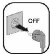
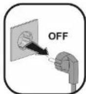
Take out the plug before any intervention. Absolutely avoid dry operation: the pump must be activated exclusively when it is immersed in water. If the water is finished, the pump must be deactivated immediately taking the plug out of the socket.
1. APPLICATIONS
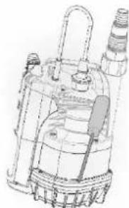
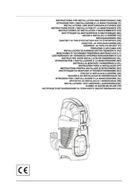
The pumps are of the submersible type, designed and made for pumping clear, for domestic uses, with manual or automatic operation, for drying basements and garages subject to flooding, for pumping drainage wells, pumping rainwater collecting traps or infiltrations from roof gutters, etc.
Thanks to their compact and handy shape, they are also used for particular applications as portable pumps for emergency situations such as for drawing water from tanks or rivers, draining swimming pools and fountains, excavations or underpasses. Also suitable for gardening and general hobby activity.

These pumps cannot be used in swimming pools, ponds or basins where people are present, or for pumping hydrocarbons (petrol, diesel fuel, combustible oils, solvents, etc.) in accordance with the accident-prevention regulations in force. They are not designed for continuous use, but for emergency use over a limited period. They should be cleaned before putting them away. See the chapter "Maintenance and Cleaning".
2. PUMPABLE LIQUIDS
| Fresh water | ● |
| Rainwater | ● |
| Clear waste water | ● |
| Dirty water | ○ |
| Foul waste water containing solid bodies with long fibres | ○ |
| Fountain water | ● |
| River or lake water | ● |
| Max. particle dimension [mm] | Ø 5 |
- Suitable
Not suitable
The pump is watertight and must be immersed in liquid to a maximum depth of 7m . See Table 3.
3. TECHNICAL DATA AND LIMITATIONS OF USE
Supply voltage: 220-240V, see electrical data plate
- Delayed line fuses (220-240V version): indicative values (Ampere)
Storage temperature: -10^ + 40^
| Line fuses 220-240V 50Hz |
| 2 Table 2 |
ENGLISH
Table 3
| Draining clear water | |||
| Model | P1=300 | P1=600 | |
| Electrical data | P1 Rated absorbed power [W] | 300 | 600 |
| Mains voltage [V] | 220-240 AC | 220-240 AC | |
| Mains frequency [Hz] | 50 | 50 | |
| Current [A] | 1.3 | 2.5 | |
| Capacitor [μF] | 8 | 12.5 | |
| Capacitor [Vc] | 450 | 450 | |
| Hydraulic data | Max. flow rate [l/min] | 125 | 195 |
| Max. head [m] | 6.5 | 9 | |
| Max. head [bar] | 0.65 | 0.9 | |
| Max. immersion depth [m] | 7 | 7 | |
| Min. AUT starting height [mm] | 115 | 115 | |
| Stopping height [mm] | 45 | 45 | |
| AUT residual water height [mm] | 2-3 | 2-3 | |
| Range of use | Length of power cable [m] | 10 | 10 |
| Type of cable | H05 RNF | H05 RNF | |
| Grade of motor protection | IP X8 | IP X8 | |
| Insulation class | F | F | |
| Liquid temperature range [℃] according to EN 60335-2-41 for domestic use | 0 ℃ / +35 ℃ | 0 ℃ / +35 ℃ | |
| Max. particle dimension [mm] | Ø 5 | Ø 5 | |
| Max. ambient temperature [℃] | +40 ℃ | +40 ℃ | |
| Weight | DNM GAS | 1" 1/4 M | 1" 1/4 M |
| Net/Gross weight approx. [kg] | 4.8 / 5.5 | 5.3 / 6 | |

The pump which does not stand on a base cannot support the weight of the pipes, which must be supported in some other way.
4. MANAGEMENT
4.1 Storage
All the pumps must be stored in a dry covered place, with possible constant air humidity, free from vibrations and dust. They are supplied in their original pack in which they must remain until the time of installation.
4.2 Transport
Avoid subjecting the products to needless impacts and collisions.
4.3 Weight and dimensions
The adhesive plate on the packaging indicates the total weight of the pump and its dimensions.
5. WARNINGS

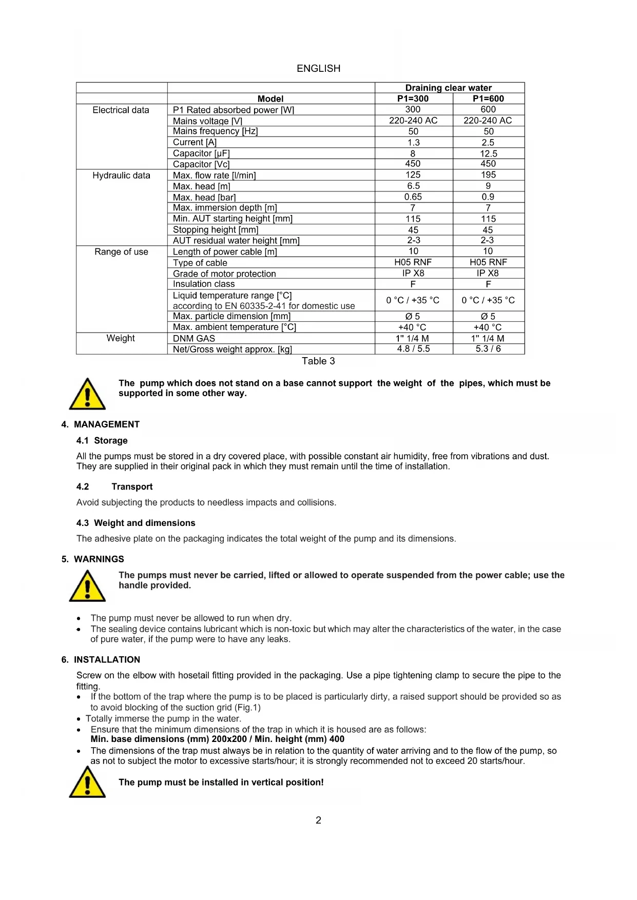
The pumps must never be carried, lifted or allowed to operate suspended from the power cable; use the handle provided.
The pump must never be allowed to run when dry.
- The sealing device contains lubricant which is non-toxic but which may alter the characteristics of the water, in the case of pure water, if the pump were to have any leaks.
6. INSTALLATION
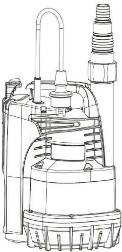
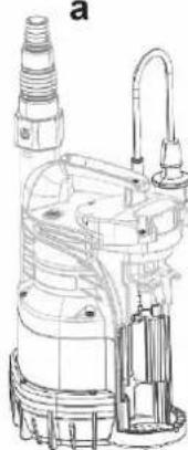
Screw on the elbow with hosetail fitting provided in the packaging. Use a pipe tightening clamp to secure the pipe to the fitting.
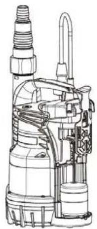
- If the bottom of the trap where the pump is to be placed is particularly dirty, a raised support should be provided so as to avoid blocking of the suction grid (Fig.1)
- Totally immerse the pump in the water.
- Ensure that the minimum dimensions of the trap in which it is housed are as follows: Min. base dimensions (mm) 200x200 / Min. height (mm) 400
- The dimensions of the trap must always be in relation to the quantity of water arriving and to the flow of the pump, so as not to subject the motor to excessive starts/hour; it is strongly recommended not to exceed 20 starts/hour.

The pump must be installed in vertical position!
ENGLISH
7. ELECTRICAL CONNECTION

The length of the power cable on the pump limits the maximum depth of immersion in use of the pump. Follow the indications on the technical data plate and in this manual, table 3.
8. START-UP
1) Insert the plug of the power cable in a 220-240V power socket.
2) When the float reaches the ON level the pump will start and will continue operating until it reaches the OFF level.
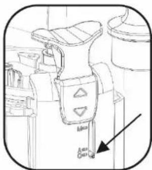
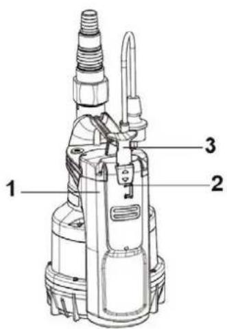
Automatic operation (A):
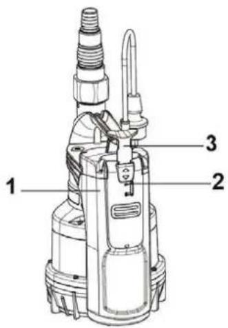
3) The integrated float switch starts and stops the pump automatically when the indicator (2) is positioned on "A".
Manual operation (M):
4) To start the pump, lift the knob (3) positioning the indicator (2) on "M". In these conditions the suction level of the pump will be down to 2-3 mm
5) In order to check the correct working and clean the float switch open the cover (1) positioning the knob (3) on "O"

9. PRECAUTIONS
RISK OF FROST: when the pump remains inactive at a temperature lower than 0^ , it is necessary to ensure that there is no water residue which could freeze, causing cracks in the plastic parts.
If the pump has been used with substances that tend to form a deposit, or with water containing chlorine, rinse it after use with a powerful jet of water in order to avoid the formation of deposits or encrustations which would reduce the characteristics of the pump.
10. MAINTENANCE AND CLEANING
In normal operation the pump does not require any type of maintenance. In any case, all repair and maintenance work must be carried out only after having disconnected the pump from the supply mains. When restarting the pump, ensure that the suction filter is always fitted so as not to create the risk or possibility of accidental contact with moving parts.
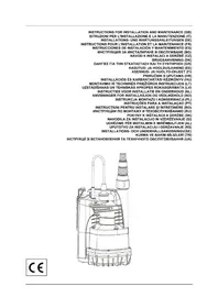
10.1 Cleaning the suction grid
(Fig.2)
- Switch off the electric power supply to the pump.
- Drain the pump.
- Unscrew the retaining screws on the filter (b).
- Remove the suction grid (c).
- Clean and reassemble the suction grid.
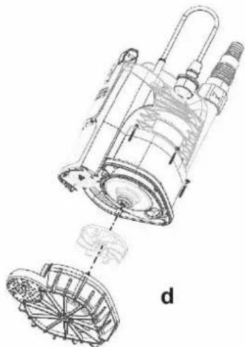
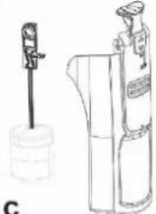
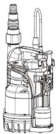
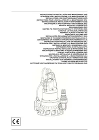
10.2 Cleaning the impeller
(Fig.3)
- Switch off the electric power supply to the pump.
- Drain the pump.
- Unscrew the retaining screws on the filter (b).
- Remove the suction grid (c).
- Wash the pump with clean water to remove possible impurities between the motor and the pump jacket. (d).
Clean the impeller (d). - Check that the impeller can turn freely.
- Assemble the parts, proceeding in inverse order to disassembly.
ENGLISH
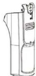
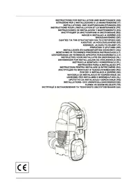
10.3 Cleaning and testing of integrated float
(Fig.4)
- Switch off the electric power supply to the pump.
- Drain the pump.
- Push the switch lever and disassemble the cover of the float.
- Remove the float, check if the material prevents the free flow and just in case proceed to cleaning.
- Assemble the parts, proceeding in inverse order to disassembly.
11. TROUBLESHOOTING

Before taking any troubleshooting action, disconnect the pump from the power supply (i.e. remove the plug from the socket). If there is any damage to the power cable or pump, any necessary repairs or replacements must be performed by the manufacturer or his authorized customer support service, or by an equally-qualified party, in order to prevent all risks.
| FAULTS | CHECKS (possible causes) | REMEDIES | |
| 1 | The motor does not start and does not make any noise. | A. Check that voltage is reaching the motor. B. Check the protection fuses. C. The switch is not activated by the float. | A. Check that the plug is inserted correctly. B. If burnt out, change them. C. - If burnt out, change them. - Increase the depth of the trap. |
| 2 | The pump does not deliver flow. | A. The suction grid or the pipes are blocked. B. The impeller is worn or blocked. C. The head required is higher than the pump's characteristics. D. Presence of air. E. Water level under the suction minimum. | A. Remove the obstructions or straighten the hose if it is twisted. B. Replace the impeller or remove the obstruction. C. Replace it with one with a higher head. D. Wait at least 1 minute until it is eliminated. |
| 3 | The pump does not stop. | A. The switch is not deactivated by the float. | A. Check that the float can move freely. |
| 4 | The flow rate is insufficient. | A. Check that the suction grid is not partially blocked. B. Check that the impeller or the delivery pipe are not partly blocked or encrusted. C. Ensure that the check valve (if contemplated) is not partially blocked. | A. Remove any obstructions. B. Remove any obstructions. C. Accurately clean the check valve. |
| 5 | The pump stops after having run for a short time. | A. The thermal overload protection device stops the pump. | A. Check that the fluid to be pumped is not too dense as it would cause overheating of the motor. B. Check that the water temperature is not too high. C. Make sure there is no solid body obstructing the impeller. D. Power supply doesn't comply with the nameplate's data. |
12. GUARANTEE

Any modification made without prior authorisation relieves the manufacturer of all responsibility. All the spare parts used in repairs must be authentic and all accessories must be authorised by the manufacturer in order to ensure maximum safety of the machines and of the systems in which they may be installed.
This product is covered by a legal guarantee (in the European Community for 24 months from date of purchase) against all defects that can be assigned to manufacturing faults or to the material used. The product under guarantee may, at discretion, either be replaced with one in perfect working order or replaced free of charge if the following conditions are observed:
the product has been used correctly in compliance with the instructions and not attempt has been made to repair it by the buyer or by third parties.
the product has been consigned to the outlet where it was purchased, attaching a document as proof of purchase (invoice or cash register receipt) and a brief description of the problem found.
The impeller and parts subject to wear are not covered by the guarantee. Intervention under guarantee does not extend the initial guarantee period in any way.
ITALIANO
INDICE
- APPLICATIONI 5
- LIQUIDI POMPABILI 5
- DATI TECHNICI E LIMITAZIONI D'USO 5
- GESTIONE 6
4.3 Bapoc kal iaoTaeic
H autokoAaTn TivakiTaou piaKetai EraW Otn OuaKeuaOia avapepei Tnv Evoeign Tou ouvoikou papous Tns nEeKtpokivntns Aviaackai Tov dioataewv Tns.
5. IPOEIAOIOIHSEI

Oi avTAEc 6ev npTeI TOTe va eTaepeovtai, va avuWovvntai n va aeitoupyoov avaptnneve c aTO Kaawio Tpofoosiaic, va xnpoiopoite TO EIKo XepouAI.
Havlaia VITpeTTI TOTe va AEToupyei Xwpi Uypo.
To eaptnma oeyavotntac Tepiexei atogikoi aattko, to otioo ouwc tpiwn diappoc n tv avtia, ptoe i va aaiowei ta xapaktnipiotika tou vepou, otav tpoketai yia kaapoe.
6. EΓΚΑΤΑΣΤΑΣΗ
Biodote n ywia me to ouvdoo foepa tou laotou utrapxie e oanoukeuaia. Etnc xnpoiotoinote eva koapo ouqipngtou owna via va opeewoeteto owna oto ouvdoo.
2. SIURBIMUI TINKAMI VANDENYS
Hacoc, He yctaHaBnBaemb Ha OCHOBaHne, He MoKeT NOdBepraTbcr Harpy3Ke Tpy6OpPobOoB, KOtopaIOnxHa 6bITb paCnpedeHe Hhblm cnocobom.
4.3KcnnnyATAUN
4.1 CkJaIupoBaHne
Bce HacocbI DnKhbI CKnaHnpoBaTbcR B KpbITOM, CyXOM NOMEueHIN, NO BO3MOxHOCTN C NOCTOHHO BnJaxHOCTbIO B03dyxa, 6e3 Bn6paun I nbJIu.Hacocbi NoCTaBnIOTcR B INX 3aBODCKOOprHnHaNbHOYNAKOBE, B KOtopoONHDOJHXbIO OCTaBaTbc BNIO TB DO MOMHTA INX MOHTaxa.
4.2 TpaHcnpTnpoBka
PepdoxpaHnTe n3dEIny OT IinuHnx yapOB nToNtKOB.
4.3 Bec npa3mepb1
HaKneIka Ha ynakOBKe yka3bIbaet o6uB BEc 3NeKtpoHacOca n ero pa3mepbl.
5. PEPENPPEKDEHNA

HacocbI HNKoIa He DoJNXbI nepeBo3ntbcra, noDHMaTbca NIN BKNIOUaTbca B NOBWeHHOM coCTOAHNN, hCNoJIb3yKa6eJIb NITaHn, nCnoJIb3yTe CneuaNAbHyOp pyKy.
Hacoc HNKoIa He DoJIKeH pa6OtaTb BCxyIO.
- YnIIOHTHeJIbHOe ycTPOINCTBO COJepKHT HeTOKCHHyO CMA3ky, KOTOPa TEm HE MeHee MOKeT N3MeHHTb CBOIcTBa BOdI, ecn peYb IeTeO uHcToB BoE, B clyae yTeYeK n3 Hacoca.
6. MOHTAXK
PnBHTte KOHe npn nmoIe3HOBOro nepexOHNka, mHeuEroC8 ynaKOBke. IcnoIb3yIe TaKKe XOMyTik dIa 3aTgNBAnH Tpy6bl, nIpNkpeNHeH Npy6bl K coeDInHeHIO.
PYCCKN
B TOM CNYUae, ecn dno KOLOua, Ha KOTOpbI NOMEuAetc HAcOC, CNbHO 3aRpa3HeH, cJeDyET npedyCMOTpeTb npINOHNrTyO ONOPy DnToro, yTO6bI n36eXaTb 3aRpa3HeHn peWetKn BCacbHaHn (Pnc.1).
- NpHocbno norgy3nte Hacoc B Body.
-ПуедусмOTиTe,чTOБьKOJOIOeДгЯpa3MeUeHINМЕЛ MHNIMaJIbHbIe pa3Mepbl,yKa3aHHbIe HIXe: Pa3Mepbl OCHOBAHn (mm) 200x200 / BbICota (mm) 400
KoIOneU BcERda OJOnKeH paCCHTbBaTbC B 3aBNCIMOCTH OT KOJIHyecTBA BObl, NOCTyNaHOSeB HAcoc, IOT pacXOda HAcoca TAKIM O6pa3OM, YTO6bI HE NIOBBepraTb DBrAteIb Ype3MEPHOMY KOJIHyecTBy NyCKOB B Yac; CTPoro He peKOMeHnyETcnpBbIuATb 20 anyckOB B Yac.

HacocdoJxeh6bItyCTaHOBJEH BepTKkaIbHOM NOIOXeHH!
7. 3JIeKTPnueCKO NOkIIOUeHne

IINHa cTeBoro Ka6eHn HAcOca OrpaHnBaet MaKcHMaJIbHyIO rIy6nHy nOrpyKeHN npn erO 3KnJyatauN BblnoJIHnTe yka3aHn, npnbedeHHbE Ha texHnuecko Ta6nueke n pykoBOdCTBe Ta6nue 3.
8.3ANYCK
1) BCTaBtB BuNk Ky Ka6eIy NtTaHnB Po3eTKy NtTaHn220-240B.
2) KOrda nonIaBok DoCTnraet ypoBHr BkJI., HAcoc BKnIOuAeTcra n npOdoNkae pa6oTaTb do doctnxHeHry ypoBHr BblKl.
Azmomamuueckpa6oma(A):
3) BCTpoeHbI IONIIABKObIy BBIKHOaTeIb ABTomATnueCKN BKIOOaET N OCTaHaBnBaET HaOC, KOrda HINKAtOp (2) yCTaHOBNEH Ha "A"
Pyha pa6oma (M):
4) IINrTO, UTO6bI HAcOC Haan paOToTb, Heo6xOIMIO NoHnTb pyKy BbIbopa (3), yCTaHOBUB INHnKaTOp (2) Ha "M" (Pnc. A). B 3TNX YcNoBnx HAcOC BCacbBaet Do 2-3 MM.
5)ДлгпрькпnpabnIbHocTn pa6Otbl nИcTObk cNeDyET OTKpbITb KpbIshky (1), yCTaHOBnB pyKBy Bb6opaВ noJoxKeHne "O"
9. IPEIOCTOPOXHOCTN
ONACHOCTb 3AMEP3AHN: KOrda HAcoc ocTaeTcH He BKnIOueHHbIM npn TemnepaType Hxke 0^ , Heo6xODmO y6eINtbc, YTO B HEM HE OCTaTKOB BObl, KOtOpBle pnp 3aMeP3AHM MOrY PnIBEcTN K TpeUHNAM IJIaCTNKOBbIX acTeN. Ecnn HACOC nONb3OBaIcB C BeIeCTBaMn, KOTOpBle IMeHTeHDeHcIIO K OTNOKeHIO INC XNOPuPOBaHHO BDOi, ONoONCHte ero nocne nCOnb3OBaHn CInbHO CTpye BObbl, YTObI N36EkaTb φOpMNPOBaHn OcaKa IN IN OTNoKeHNI, KOtOpBle CHNKAoiT EKcnllyaatauOHHbIe XapakTePncTNKn Hacoca.
10. TEXHINCHECKOE OBCJNYKBAHNE IN YNCTKA
B HopmaIbHOM pa6oHem pexnme 3neKtpoHaocc He hyxdaetcB KAKOM-Ni6o Texnueckom 06CnykBaHH. B JIO6OM cnUyae BCE pa60tI NO pEMOHTy nTexnueckomy 06CnykBaHHIO DOnXhBI OcyuieCTBIAITBCR NOCNE OTCOeINHeHNA HACOa OT cETN 3neKtpoNTAHJ. PnI nepezanycke HAcoca npOBepuTB, YTObI BCaCbIBaHOUI qINbTp 6BJN BCERDa HA MeTe BO n36BeKaHHe ONaCHOCTn INI BO3MOXHOCTn CUYauHOrO KOHTaC NODBHXHBIM OPraHAM.
PYCCKN
10.1 Ynctka BcacbIbaIOe peWTeKN
(Cxema 2)
- ObecToHTb Hacoc.
CJNTbBOyuH3Haocca.
OTBnHTITE KpeNExHbIe BNHTbHa qnIbTpE (b). - ChrMb BcacbBaioyIO peWetKy (c).
- IpoHCTnTb n yctaHOBnTb Ha MeCTO BcAcbIaIOUyIO peUeTKy.
10.2 YncTkKa KpbIbIb4aTkn
(Cxema 3)
- ObecToHb Haoc.
CINTBBOUYHacocca. - OTBHTnTe KpeNExKHbIe BnHTbI Ha qnJIbTpE (b).
- Chrtb BcacbBaioyIO peWetKy (c).
- PpOmbIbHacoccHCToBBOJOn, ydaJIaR Bce BO3MOXHbIE 3aPp3HeHH MEXdy DnBraTeJeM N KOKyXOM HAcoca (d).
- IpounCTnTb KpbIbuaTky (d).
- PioBepntb, YTO6bl KpbInbHaTka Bpaaanaacc CBO6oHNo.
CobpaTb BCE KOMIIeKTuOuIe B nopAKe, oBpaTHomy demoHTaKy.
10.3 OuNCTka n npOBepka BcTpoeHHoro nonJaBka
(Cxema 4)
- ObecToHb Hacoc.
CINITb BOyu n3 Hacoca. - IpoToIKNHnTe pbHar BbIKNoHcATEJN N DEMoHTnpyTKe KpbIuKy nonNaBaKa.
- BbIbTe nonIaBok, npOBepbTe, Het IIN MaTePnAna, KOtOpbM Me7aET HopMaIbHOMy DBrXeHIO, npH Heo6xoIIMOCTn npOn3BeDITe OCHcTKy.
- PpOBePntb, YTO6bI KpbIbUaTka BpaUanacb CBO6oJHo.
CobpaBt Bce KOMJIeKToUoINe B nopAaTHOmy dmoHTaKy.
11. NONCK HENCPABHOCTEIN

Ipeed Tem, KaK NaHnHaTb NOnCK HeNCnpaBnOteN, Heo6xOdmo OToCoeINHTb 3JeKtpnueckoe NtTaHne OT Hacoca (BbHyTb BnIKy n3 po3eTKn). Ecn KabeNb NtAnHn NIn NIO6a 3JeKtpnuceKa YAcTB HAcoca NobPexKeHbl, onepaun no 3amHe nn peMOHTy DoJXHaBbINOJIHbTc npOn3BODnteMe nn erO cny6boi TexcepBnca nn KBaNNfNpUOBaHHbIM YenOBekOM, T06bl N36ExKaTb BO3MOXhBX OnaChOCTe.
4.3 Teza in velikost
Na nalepki na embalazi je navedena skupna teza elektricne crpalke in njena velikost.
5. OPOZORILO

- INDEX
- WARNING
- APPLICATIONS
- PUMPABLE LIQUIDS
- TECHNICAL DATA AND LIMITATIONS OF USE
- ENGLISH
- MANAGEMENT
- Storage
- Transport
- Weight and dimensions
- WARNINGS
- INSTALLATION
- ELECTRICAL CONNECTION
- START-UP
- Automatic operation (A):
- Manual operation (M):
- PRECAUTIONS
- MAINTENANCE AND CLEANING
- Cleaning the suction grid
- (Fig.2)
- Cleaning the impeller
- (Fig.3)
- Cleaning and testing of integrated float
- TROUBLESHOOTING
- GUARANTEE
- ITALIANO
- INDICE
- Bapoc kal iaoTaeic
- IPOEIAOIOIHSEI
- EΓΚΑΤΑΣΤΑΣΗ
- SIURBIMUI TINKAMI VANDENYS
- 4.3KcnnnyATAUN
- CkJaIupoBaHne
- TpaHcnpTnpoBka
- Bec npa3mepb1
- PEPENPPEKDEHNA
- MOHTAXK
- PYCCKN
- 3JIeKTPnueCKO NOkIIOUeHne
- 8.3ANYCK
- Azmomamuueckpa6oma(A):
- Pyha pa6oma (M):
- IPEIOCTOPOXHOCTN
- TEXHINCHECKOE OBCJNYKBAHNE IN YNCTKA
- Ynctka BcacbIbaIOe peWTeKN
- (Cxema 2)
- YncTkKa KpbIbIb4aTkn
- (Cxema 3)
- OuNCTka n npOBepka BcTpoeHHoro nonJaBka
- (Cxema 4)
- NONCK HENCPABHOCTEIN
- Teza in velikost
- OPOZORILO
Brand : TALLAS
Model : DCWP 600
Category : Water pump