Indego 1200 Connect - Lawn mower BOSCH - Free user manual and instructions
Find the device manual for free Indego 1200 Connect BOSCH in PDF.
User questions about Indego 1200 Connect BOSCH
0 question about this device. Answer the ones you know or ask your own.
Ask a new question about this device
Download the instructions for your Lawn mower in PDF format for free! Find your manual Indego 1200 Connect - BOSCH and take your electronic device back in hand. On this page are published all the documents necessary for the use of your device. Indego 1200 Connect by BOSCH.
USER MANUAL Indego 1200 Connect BOSCH
OBJ_DOKU-27378-008 In Page 1 Taxday, October 27, 2015 10:34 AM
ana agnosaererae aeguidae aesusae

Robert Bosch GmbH
Power Tools Division
70764 Leinleider-Echterdingen
GERMANY
www.bosch-garden.com
F016L81517(2015.1010/457 EURO)

Indego | Indego 800 | Indego 850 | Indego 1000 Connect | Indego 1100 Connect | Indego 1200 Connect

de Originalbetriebsanleitung
en Original instructions
fr Notice original
es Manual original
pt Manual original
it Istruzioni original
n Orsorpanikolike gebruksaanwiring
da Dnaugrupsanwiring
sv Bruskanisming ioriginal
no Original driftinsbrus
f Klakpperaset object
sr Originalo nputstvo zad sl Izvina navodita
lr Originalo uputo zad
el Agusrane kastusuhjeru
IInkstrukturas originalitate
It Originaln instructura
sr Original nputstvo zad sl Izmo na vodada hr Original nputstvo zad et Aluparane kastusuhjeriv Instrukturas iqorinalvatalde It Original instruktura

Deutsch. 15
English. Page 31
Francais. Page 46
Espanol . Pagina 63
Portugues.. Pagina 79
Italiano.. 96
Nederlands.. 113
Dansk. Side 129
Svenska. Sida 144
Norsk. Side 159
Suomi. .Sivu 174
EAAynvka. 2eA6a189
Türkce Sayfa 207
Polski. Strona 223
Cesky. Strana 242
Slovensky. Strana 257
Magyar Oldal 273
Pycckn ..CtpaHua 290
YkpaHcbKa. CtopiHa 309
Romana.. .Pagina 326
BbIrapckn. 3paHua 343
Srpski. Strana 361
Slovensko Stran 377
Executive Vice President
Engineering
Helmut Heinzelmann
Head of Product Certification
PT/ETM9

i. v.k = u _____
Robert Bosch GmbH, Power Tools Division
70764 Leinfelden-Echterdingen, GERMANY
www.bosch-garden.com
Thank you for purchasing the Indego Robotic Mower.
Please read the safety instructions provided below before installing the Indego.
Safety Notes
Warning! Read these instructions carefully, be familiar with the controls and the proper use of the machine. Please keep the instructions safe for later use!
Explanation of symbols on the machine

General hazard safety alert. Ensure no exits are blocked or obstructed by the machine.

Warning: Read user instructions before operating the machine.

Warning: Operate the disabling device before working on or lifting the machine.

Caution: Do not touch rotating blades. Sharp blade(s). Beware of severing toes or fingers.

Wait until all machine components have completely stopped before touching them. The
blades continue to rotate after the machine is switched off, a rotating blade can cause injury.

Pay attention that bystanders are not injured through foreign objects thrown from the machine.

Warning: Keep a safe distance from the machine when operating.

Do not ride on the machine.

Battery charger contains a safety transformer.
D□C
Detachable supply unit.
Do not use a high-pressure washer or a garden hose to clean the robotic mower.
32 | English
Operation
Before working on the machine itself (e.g. maintenance, tool change, etc.) as well as during transport and storage, remove the isolator key from the machine.
- Never allow children or people unfamiliar with these instructions to use the machine. Local regulations may restrict the age of the operator.
This machine is not intended for use by persons (including children) with reduced physical, sensory or mental capabilities, or lack of experience and knowledge, unless they have been given supervision or instruction concerning use of the machine by a person responsible for their safety. Children should be supervised to ensure that they do not play with the machine.
The operator or user is responsible for accidents or hazards occurring to other people or their property.
If any hazard occurs whilst the machine is operating immediately press the red stop button.
Ensure correct installation of the perimeter wire as instructed.
Check the perimeter wire is fully pegged to the ground avoiding any slack lengths of wire.
Periodically inspect the area where the machine is used and remove all stones, sticks, wires and other foreign objects.
Do not run any live mains cables in the working area.
Periodically inspect to see that the blades, blade bolts and cutter assembly are not worn or damaged. Replace worn or damaged blades and bolts in sets to preserve balance.
- Never operate the machine with defective guards or without safety devices.
Do not put hands or feet near or under rotating parts.
- Never pick up or carry the machine while the motor is running.
Do not leave the machine to operate unattended if you know that there are pets, children or people in the immediate vicinity.
- Start the machine according to the instructions standing well away from rotating parts.
Do not use the product at the same time as a sprinkler or use the schedule to ensure that the two systems never run simultaneously.
Do not modify this product. Unauthorized modifications may impair the safety of your product and may result in increased noise and vibration.
Remove the isolator key:
before clearing a blockage,
before checking, cleaning or working on the machine,
- if the machine vibrates abnormally (stop and check immediately),
- after striking a foreign object. Inspect the machine for damage and get advice on necessary repairs from your Bosch Service Centre.
English | 33
Maintenance
Always wear gardening gloves when handling or working near the sharp blades.
Before working on the machine itself, remove the isolator key.
Before working on the docking station or power supply, remove plug from mains.
Clean the exterior of the machine thoroughly using a soft brush and cloth. Do not use water, solvents or polishes.
Remove all grass and debris, especially from the ventilation slots.
Turn the machine on its back and clean the blade area regularly. Use a stiff brush or scraper to remove compacted grass clippings. (see figure A)
Blades are reversible. (see figure B)
- Keep all nuts, bolts and screws tight to be sure that the machine is in safe working condition.
Periodically visually inspect the machine and replace worn or damaged parts for safety.
Ensure that only official Bosch replacement parts are used.
Replace all blades and bolts as a set as required.
Winter Storage and Transportation
Remove isolator key when storing.
The Indego will operate between 5^ and 45^ . During the winter season once the temperature in the garden is consistently below 5^ store the machine and the docking station in a secure, dry place, out of the reach of children.
Do not place other objects on the machine or docking station.
It is recommended to use the original packaging when transporting the Indego over long distances.
SD-Card
The machine has a SD-Card interface for use by the Bosch Service Centre only for software diagnosis.
Battery Hazards
- Recharge only in the Bosch approved docking station.
The Indego will operate between 5^ and 45^ . If the battery is outside this range the Indego will display on screen that the temperature is out of range and will not leave the docking station. If operating it will return to the docking station.
In the unlikely event of liquid being ejected from the battery avoid all contact with the machine. If contact with the liquid occurs, seek medical advise.
If the battery becomes defective, liquid can escape and come into contact with adjacent components. Check any parts concerned and contact the Bosch Service Centre.
Do not open the machine and battery inside. Danger of short-circuiting and electric shock.
Protect the machine against fire. Danger of battery explosion.
In case of damage and improper use of the machine, vapours may be emitted from the battery. Pro
34|English
vide for fresh air and seek medical help in case of complaints. The vapours can irritate the respiratory system.
- Store the machine only within a temperature range between -20^ and 50^ . As an example, do not leave the machine in the car in summer.
SafetyWarnings for Docking Station and Power Supply
Only charge via the official Bosch docking station. Otherwise there is danger of fire and explosion.
Check the docking station, power supply, cables and plugs periodically. If damage is detected, do not use the docking station or power supply. Never open the docking station or power supply. Have repairs performed only by a qualified Bosch technician and only using original spare parts. A damaged docking station, power supply, cable or plug increases the risk of an electric shock.
Do not operate the docking station and power supply on easily flammable surfaces (e.g., paper, textiles, etc.) or surroundings. The heating of the docking station and power supply during the charging process can pose a fire hazard.
Warning: for the purposes of recharging the battery, only use the detachable supply unit provided with this appliance.
Supervise children at all times. This will ensure that children do not play with the docking station, power supply or the machine.
Children or persons that owing to their physical, sensory or mental limitations or to their lack of experience or knowledge, are not capable of safely operating the docking station or power supply, may only use this docking station and power supply under supervision or after having been instructed by a responsible person. Otherwise, there is danger of operating errors and injuries.
The voltage indicated on the power supply must correspond to the voltage of the power source.
The power supply should ideally be connected into a socket that is protected by a circuit-breaker that is actuated by a 30mA residual current. Check your Residual Current Device (RCD) at regular intervals.
The supply cord must be inspected for signs of damage at regular intervals and may only be used if in perfect condition.
If the supply cord is damaged, it must be replaced by the manufacturer, its service agent or similarly qualified persons in order to avoid a hazard.
Only use or replace cables for the docking station and power supply with Bosch approved parts.
- Never touch the mains plug with wet hands.
Do not run over, crush or pull the cables. Protect the cables from heat, oil and sharp edges.
The power supply is double insulated for safety and requires no earth connection. The operating voltage is 230VAC 50Hz (for non-EU countries 220V 240V as applicable). Contact your Bosch Service Centre for details. If in doubt contact a qualified electrician or the nearest Bosch Service Centre.
The connection lead must be inspected for signs of visible damage and ageing at regular intervals and may only be used if in perfect condition.
Products sold in GB only: Your product is fitted with a BS 1363/A approved electric plug with internal fuse (ASTA approved to BS 1362).
If the plug is not suitable for your socket outlets, it should be cut off and an appropriate plug fitted in its place by an
authorised customer service agent. The replacement plug should have the same fuse rating as the original plug. The severed plug must be disposed of to avoid a possible shock hazard and should never be inserted into a mains socket elsewhere.
Symbols
The following symbols are important for reading and understanding the operating instructions. Please take note of the symbols and their meaning. The correct interpretation of the symbols will help you to use the garden product in a better and safer manner.
Symbol Meaning

Wear protective gloves

Permitted action

Prohibited action

Accessories/Spare Parts
Intended Use
The garden product is intended for domestic lawnmowing.
Technical Data
| Robotic Lawnmower | Units | Indego | Indego 800 | Indego 850 | Indego 1000 Connect | Indego 1100 Connect | Indego 1200 Connect |
| Article number | 3600......HA2 0../ ... HA2 1.. | ... HA2 1.. | ... HA2 1.. | ... HA2 3.. | ... HA2 3.. | ... HA2 3.. | ... HA2 3.. |
| Cutting width cm 26 26 | 26 26 26 26 | ||||||
| Height of cut | mm | 20 - 60 | 20 - 60 | 20 - 60 | 20 - 60 | 20 - 60 | 20 - 60 |
| Slope angle (max.) | ° | 20 | 20 20 | 20 20 | |||
| Working area size | |||||||
| - maximum | \( m^2 \) | 800/1000* | 800 | 850 | 1000 | 1100** | 1200** |
| - minimum | \( m^2 \) | 20 | 20 | 20 | 20 | 20 | 20 |
| - per charge up to*** | \( m^2 \) | 200 | 200 | 200 | 200 | 200 | 200 |
| Weight | kg | 11.1 | 11.1 | 11.1 | 11.1 | 11.1 | 11.1 |
| Degree of protection | IPX1 | IPX1 | IPX1 | IPX1 | IPX1 | IPX1 |
Serial number
see type plate on the garden product
Subject to variant
Subject to the lawn area shape and complexity (see examples in figure 3)
Depends on cutting height, grass conditions and moisture
The values given are valid for a nominal voltage [U] of 230 V. For different voltages and models for specific countries, these values can vary.

36 | English
| Robotic Lawnmower | Units | Indego | Indego 800 | Indego 850 | Indego 1000 Connect | Indego 1100 Connect | Indego 1200 Connect |
| Battery | Li-Ion Li-Ion Li-Ion Li-Ion Li-Ion | ||||||
| Rated voltage | V 32.4 | 32.4 | 32.4 | 32.4 | 32.4 | 32.4 | |
| Capacity | Ah 3.0 | 3.0 | 3.0 | 3.0 | 3.0 | 3.0 | |
| Number of battery cells | 18 | 18 | 18 | 18 | 18 | ||
| Operating time, average up to*** min 50 50 50 50 50 50 | |||||||
| Charging period (max.) | min 50 50 | 50 | 50 | 50 | 50 | 50 | |
| Perimeter Wire | |||||||
| Perimeter wire | |||||||
| - Wire supplied | m | 150/200* | 150 | 150 | 200 | 200 | 250 |
| - minimum working length | m | 20 | 20 | 20 | 20 | 20 | 20 |
| - maximum working length | m | 450 | 450 | 450 | 450 | 450 | 450 |
| Docking Station | |||||||
| Article number | F 016 ... | ...L69 104 | ...L69 104 | ...L69 104 | ...L69 104 | ...L69 104 | ...L69 104 |
| Input voltage | V | 42 | 42 | 42 | 42 | 42 | |
| Power consumption | W | 150 | 150 | 150 | 150 | 150 | 150 |
| Charging current | A | 2.0 | 2.0 | 2.0 | 2.0 | 2.0 | 2.0 |
| Allowable charging temperature range | °C | 5 - 45 | 5 - 45 | 5 - 45 | 5 - 45 | 5 - 45 | 5 - 45 |
| Weight | kg 2.0 | 2.0 | 2.0 | 2.0 | 2.0 | 2.0 | |
| Degree of protection | IPX1 | IPX1 | IPX1 | IPX1 | IPX1 | IPX1 | |
| Power Supply | |||||||
| Article number | |||||||
| Switzerland | F 016 ... | ...L69 117 | ...L69 117 | ...L69 117 | ...L69 117 | ...L69 117 | ...L69 117 |
| United Kingdom | ...L69 118 | ...L69 118 | ...L69 118 | ...L69 118 | ...L69 118 | ...L69 118 | |
| Rest of Europe | ...L69 116 | ...L69 116 | ...L69 116 | ...L69 116 | ...L69 116 | ...L69 116 | |
| Australia | ...L69 119 | ...L69 119 | ...L69 119 | ...L69 119 | ...L69 119 | ...L69 119 | |
| Input AC | V | 220 - 240 | 220 - 240 | 220 - 240 | 220 - 240 | 220 - 240 | 220 - 240 |
| Protection class | ☐ /Π | ☐ /Π | ☐ /Π | ☐ /Π | ☐ /Π | ☐ /Π | |
| Frequency | Hz | 50/60 | 50/60 | 50/60 | 50/60 | 50/60 | 50/60 |
| Output DC | V | 42 | 42 | 42 | 42 | 42 | |
| Degree of protection | IPX7 | IPX7 | IPX7 | IPX7 | IPX7 | IPX7 | |
| Weight | kg 2.0 | 2.0 | 2.0 | 2.0 | 2.0 | 2.0 | |
*Subject to variant
*Subject to the lawn area shape and complexity (see examples in figure 3)
Depends on cutting height, grass conditions and moisture
The values given are valid for a nominal voltage [U] of 230 V. For different voltages and models for specific countries, these values can vary.
Noise/Vibration Information
Sound emission values determined according to EN 50636-2-107.
Typically the A-weighted noise levels of the product are:
Sound pressure level 64 dB(A); sound power level 72 dB(A).
Uncertainty K = 2.74 dB.
Declaration of Conformity
C
We declare under our sole responsibility that the product described under "Technical Data" is in conformity with all relevant provisions of the directives 2006/42/EC, 1999/5/EC (until 13 June 2016), 2014/53/EU (from 14 June 2016), 2000/14/EC, 2009/125/EC, 2011/65/EU including their amendments and complies with the following standards: EN 60335-1:2012+A11:2014/EN 50636-2-107:2015 (Product safety), EN 61558-1:2005+A1:2009/ EN 61558-2-16:2009+A1:2013 (Power Supply safety),


EN 301 489-7 V1.3.1 (EMC and ERM for GSM and DCS), EN 301 511 V9.0.2 (GSM 900 and GSM 1800 Bands Essential Requirements), EN 55014-1:2006+A2:2011 (EMC
Emissions),EN 55014-2:1997+A2:2008 (EMC Immunity). Guaranteed sound power level 75 dB(A).
Conformity assessment procedure according to Annex VI. Equipment category: 32
Notified body for 2000/14/EC:
SRL, Sudbury, England, Nr. 1088
Technical file (2006/42/EC, 2000/14/EC) at:
Bosch Lawn and Garden Ltd., PT-HG/ENS-PA2, Stowmarket, Suffolk IP14 1EY, England
Henk Becker
Executive Vice President
Engineering
Helmut Heinzelmann
Head of Product Certification
PT/ETM9

Robert Bosch GmbH, Power Tools Division 70764 Leinfelden-Echterdingen, GERMANY Leinfelden, 27.10.2015
Explanation of Installation Guide (seepages3-14)
| Action Figure Page | |
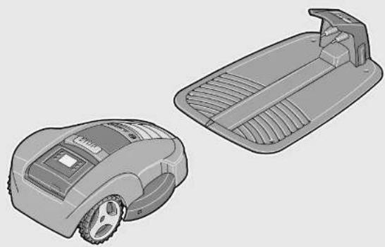
| Delivery scope/unpacking product | 1 4 |
| Position the docking station | 2 - 4 4 - 6 |
| Thread wire through base plate | 5 6 |
| Connect first end of perimeter wire | 6 6 |
| Fix docking station to the ground | 7 6 |
| Lay out perimeter wire | 8 7 |
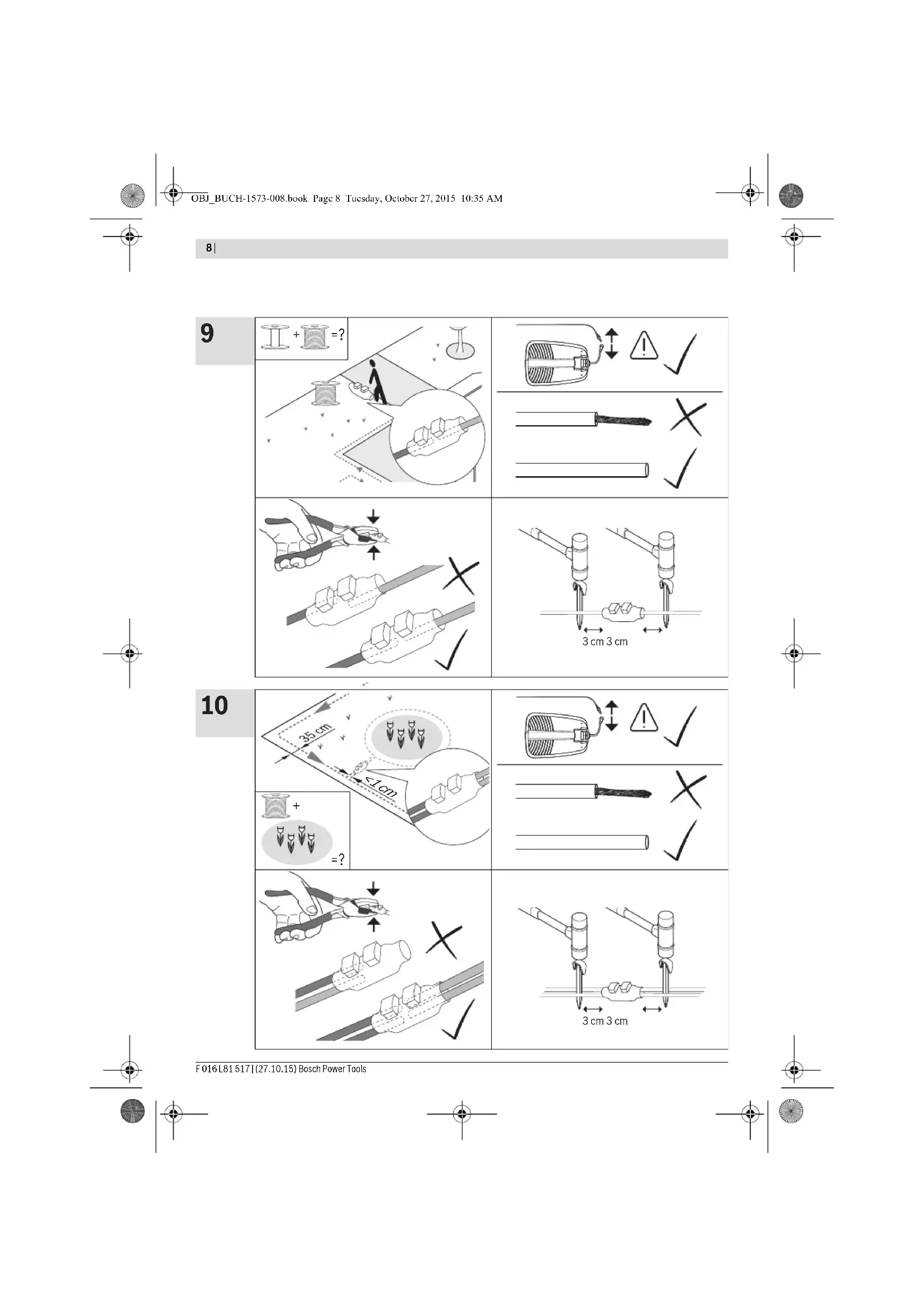
| Extend perimeter wire | 9 8 |
| Lay out additional area with perimeter wire 10 8 | |
| Connect second end of perimeter wire | 11 9 |
| Clip on protective cover of docking station | 12 9 |
| Install power supply | 13 10 |
| Docking station indicates power on | 14 10 |
| Plug in isolator key | 15 10 |
| Charge battery by putting the machine into docking station | 16 11 |
| Welcome screen = Refer to manual | 17 11 |
| Lift up and carry the machine | 18 12 |
| Set height of cut | 19 12 |
| Logicut Intelligent Cutting | 20 13 |
| Cleaning | A 14 |
| Maintenance | B 14 |
Lawn Preparation
Remove stones, loose pieces of wood, wire, live mains cables and other foreign objects from the cutting area.
Make sure that the cutting area is even and has no ditches, grooves and steep slopes above 20^ that are clear obstructions for the machine.
Cut the main area of the lawn with a conventional mower to a max. height of 40mm and the perimeter wire area to a max. height of 20mm .
Installation
For a video guide on how to install the Indego please visit www.bosch-indego.com or use the following QR-Code.

Select a position for the docking station, horizontally levelled and out of direct sunlight.
Note: The docking station must be positioned on the wire at an outer edge of the cutting area. It cannot be positioned by the side of a shed or workshop that appears as an island within the cutting area.
Make sure that the docking station is placed beside the cutting area with a straight 1.5 m track in front of the docking station and a straight 1 m track behind. Whilst stood in the grass area to be cut it is important that the docking station charging pins point to the left. (see figure 2)
Note: If the docking station is positioned with the charging pins pointing either into the grass area or pointing to the right the Indego will not run correctly.
Pull the wire end through the front hole of the base plate and straight through the wire duct and the rear hole. Fix the wire with a peg inline with the hole. Cut off insulation carefully and connect the wire to the right hand (red) terminal. (see figures 5-6)
Fix the docking station with 4 supplied fixing pins to the ground. (see figure 7)
Lay out the perimeter wire anti-clockwise and flush to the ground. Observe the minimum distances from lawn edges, steps, walls, ponds, etc. Use the spacing guide. (see figure 8)
Note: The cable should be positioned so that the Indego will not be more than 16 m away at anytime.
If the working area borders against a flat path or surface that is level with the lawn the Indego will be able to run over it. In such cases the perimeter wire should be positioned right up to the edge of the lawn.
Note: Perimeter wire can be buried up to a maximum depth of 5 cm. It is recommended to mark out permanent objects within the garden. This will prevent the Indego colliding with the object and reduce wear on the shell. Objects on the lawn below 6 cm height e.g. trees, ponds, flower beds etc. must be delimited in a clockwise direction. The
38|English
lines to and from these zones may not cross but the wire should be touching. (see figure 8)
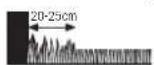
Note: Approximately 20 cm of lawn around the fixed object and around the edge of the lawn will not be mown.
Fix the wire with the first peg next to the docking station, tension and fix with pegs at a distance of approx. 50~cm (see figure 8)
Continue the loop and bring the wire to the back of the docking station and inline with the other end of the wire. Fix the second end of the wire also with the peg. Perimeter wire and peg should be installed inline. Shorten the wire, cut off insulation carefully and connect the wire to the left hand (black) terminal. (see figure 11)
Clip on the protective cover of the docking station. (see figure 12)
Note: If extra perimeter wire is required this can be added using one connector. (see figure 9)
The wire can be extended up to the maximum allowed length of 450m
Note: If verticutting or raking is intended avoid the perimeter wire.
Install the power supply in a cool, dry environment. Connect it with the docking station and an indoor mains socket. (see figure 13)
Check the indicator on the docking station (see figure 14):
Indicator lights up continuously green, if the output voltage of the power supply is available and the perimeter wire is not interrupted.
Indicator does not light up when the output voltage of the power supply is not available.
Initial Setup
Plug the isolator key into the machine and put it into the docking station for charging. (see figures 15 - 17)
The welcome screen appears and shows following symbols:
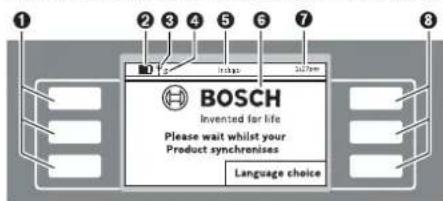
Symbol Meaning
Multifunctional buttons, left
Battery capacity
Mower connected to GSM network
Waiting to connect to the GSM network
S Mower connected to server
*Waiting to connect to the server
Symbol Meaning
Title of Menu/Submenu
Display with dialog screens
Time
Multifunctional buttons, right
^ Indego...Connect
The buttons are multifunctional. The meaning depends on the individual menu function and is explained on the screen.
The buttons next to the arrow symbols allow to navigate up or down through the menu options. The buttons next to the arrow symbols allow to go right or left through the menu options.
The display will change to the next screen as soon as any option is selected and confirmed.
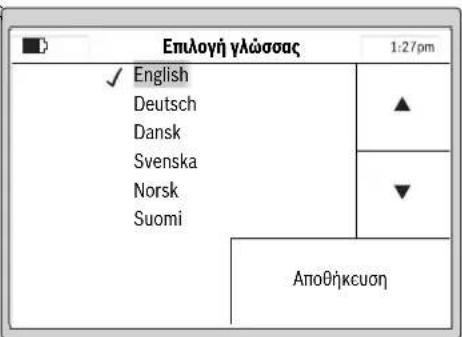
Installation
First press the button next to "Language choice". The "Set Language" screen appears and shows the following.
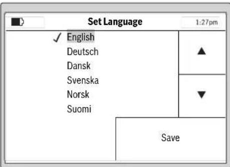
Select one of the Language options and confirm with "Save".
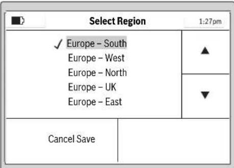
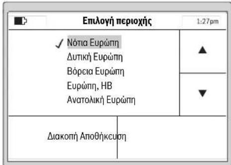
Select the region where the Indego is located and confirm with "Save".
This information will be used by the e-compass in the robotic lawnmower for a better performance of the Indego.


English | 39
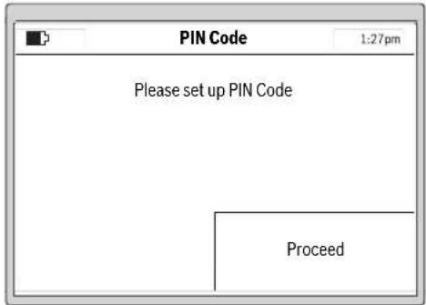
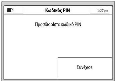
Select "Proceed" to enter your personal PIN Code.
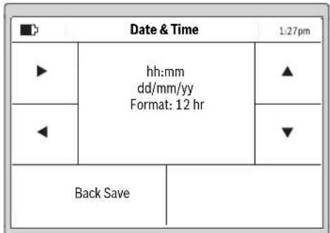
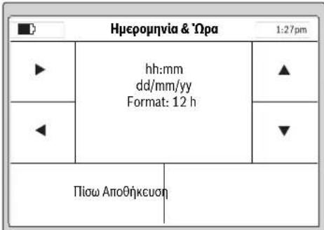
Select the "hh:mm", "dd/mm/yy" and "Format: 12 hr" input positions with the left/right cursors, adjust the values with the up/down cursors and confirm with "Save" or select "Back" to return to the first "PIN code" screen.
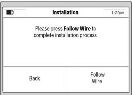
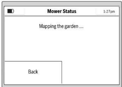
Press "Follow Wire" to map the garden.
(Select "Back" to return to the "Date & Time" screen.)
Note: If the Indicator on the docking station flashes at this point the perimeter wire is broken, too long (above 450 m) or too short (below 20 m).
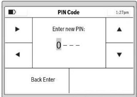
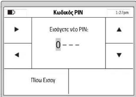
Select the input position with the left/right cursors, adjust the digits with the up/down cursors and confirm with "Enter" or select "Back" to return to the first "PIN Code" screen.
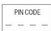
Please make a note of your PIN Codehere.
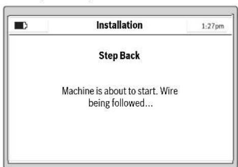
The following screen indicates the initial follow of perimeter wire:
Note: Keep the PIN code secret from third parties.
If you have lost your personal PIN code, you will have to return the Indego and its docking station to a Bosch Service Center to be unlocked. Please contact your dealer or Bosch (see "After-sales Service and Application Service").
The blades do not rotate when the machine follows the wire for the first time.


40 | English
Note: Whilst mapping the Indego will follow the wire around the edge of the lawn area. Where the wire is run to and from an obstacle within 1cm as described the Indego will not detect the wire but continue along the wire around the perimeter of the lawn. (see figure 8)
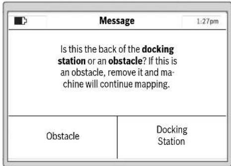
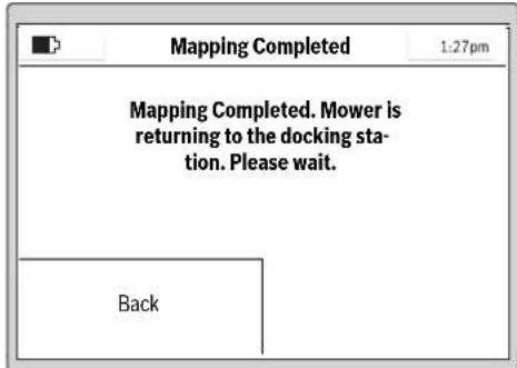
Mapping is complete when the machine reaches the back of the docking station.
If the machine hasn't reached the back of the docking station press "Obstacle" and observe information indicated on the screen to complete installation.
If the machine has reached the back of the docking station press "Docking Station".
After a successful installation you can either immediately begin to mow by pressing "Mow now" or set up a mowing schedule in the "Menu > Change Schedule".
For more information about the behaviour of the machine while mowing see section "Mowing".
Setup of Mowing Schedule
Configure the mowing schedules and the settings of the machine according to your needs.
Approximate runtimes to complete a full garden coverage are quoted below. Please note that the runtimes will vary depending on the lawn complexity and number of objects within the lawn area.
| 200 m² | 2 h |
| 500 m² | 6 h |
| 800 m² | 9 h |
| 1000 m² | 12 |
| 1200 m² | 15 |
All menu items are listed in section "Menu Navigation". The set up of a "Schedule" is explained in detail. The other menus are self explaining.
Schedule
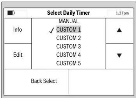
In "Menu > Change Schedule" 5 schedules are available. "MANUAL" should be used if you only want to instruct the machine to operate at the current time.
Each of the "CUSTOM" mode can be scheduled according to your needs.
Example:
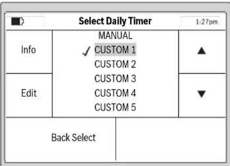
Select a "CUSTOM" schedule with the up/down cursors, e.g. "CUSTOM 1" and press "Edit".
English | 41
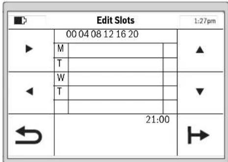
Select the mowing day with the up/down cursors, e.g. "M". Set up a start time slot for the selected day with the right/left cursors.
Confirm the start time by pressing the bottom right arrow. Set up an end time for the slot with the right/left cursors. Confirm the end time by pressing the bottom right arrow.
The machine will work within a slot unless the battery needs charging. If the lawn area has been completed before the end of a time slot the machine will return to the docking station.
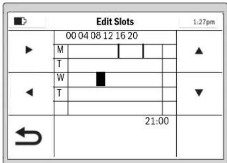
The programmed slot is shown on a schedule.
A tick will appear next to the saved mode.
The machine will start mowing as soon as day and start time of slot 1 is reached.
Note: Set up different schedules for seasonal growing conditions in spring, summer and autumn. Observe the growth of the grass and adjust your schedule if required.
Mowing
Do not let children ride the machine.
Press manual stop button before lifting. Always lift the machine at its handle.
Height of cut: The height of cut for the Indego can be adjusted between 20mm and 60mm (see figure 19). The height of cut dial offers 10 separate settings (approx. 20mm , 24mm , 29mm , 33mm , 38mm , 42mm , 47mm , 51mm , 56mm and 60mm ).
Note: The Indego's cutting system is designed to cut small lengths of grass (3-5 mm) so that the clippings can mulch down and fertilise the lawn.
Note: For the first 3 weeks of usage set the height of cut between 5 and MAX to prevent the perimeter wire being cut. After 3 weeks the wire will be covered by the lawn.
For best mowing results, set up a frequent mowing schedule for longer lasting battery and for preventing debris on the lawn.
Once mowing has started:
- in the "Manual" mode, the machine operates until the lawn area has been cut or until the manual stop button is pressed. It only pauses mowing for charging.
- in the programmable "Custom" mode, the machine operates continuously within a slot. It only pauses mowing for charging. To stop mowing before the machine has finished a slot, press the manual stop button. If the lawn area has been completed before the end of a time slot the machine will return to the docking station.
Set up all additionally required mowing days and confirm your personal "CUSTOM 1" mowing schedule by pressing the bottom left arrow (return).
To delete a slot move the cursor to the corresponding time and press the bin icon which will appear in the bottom right corner.
42 | English
Logicut Intelligent Cutting
How the Indego cuts efficiently (see figure 20)
To mow efficiently the Indego learns the shape of the cutting area it is working in. This learning occurs during the first two cutting cycles.
Below is an explanation of how the Indego learns the lawn shape.
How it works
To mow efficiently the Indego maps the outline of the lawn area and the location of the objects within it (trees, flowerbeds, ponds, etc) that are marked out with perimeter wire during installation. This allows the Indego to plan where it needs to cut the grass, where it has cut the grass and also its route to and from the docking station. This allows the Indego to complete the task of mowing more efficiently.
Mapping the cutting area (see figure 20)
After setup the Indego will first map out the shape of the garden. This is done by following the perimeter wire placed around the edge of the garden. Whilst following the perimeter wire the Indego is measuring the distances. The Indego then builds up a map of the garden that is saved into its memory.
Note: The Indego does not follow the wire to the inner boundaries.
Learning the location of garden objects marked out with the perimeter wire (see figure 20)
Once the Indego has the cutting area mapped it can start to cut the grass. After pressing "Mow Now" the Indego will leave the docking station and start to cut the grass in parallel lanes. For accuracy the parallel lanes are limited to approximately 10m . It will continue cutting in these lanes until it completes a section of the cutting area or until it discovers an object that has been marked out using the perimeter wire.
Once an object is discovered the Indego will follow the perimeter wire around it to establish its shape. The Indego will then drive to the perimeter wire at the edge of the cutting area to confirm the location of the object within the garden map. The Indego will then continue mowing. This process will be repeated if the Indego discovers additional objects whilst mowing. The Indego will complete the mowing then return to the docking station.
Note: This process will be continued the 2nd time the Indego cuts the grass. This is to make sure that all objects in the garden are discovered and their location on the garden map is accurately logged.
If there are no more objects in the garden the Indego will continue to cut the grass as normal.
In case a new inner boundary (e.g. flower bed) should be marked up after the installation is complete, this can be done by adding extra cable with a wire connector. (see figure 10)
Mowing mode (see figure 20)
Once the Indego has learnt the location of all the objects in the garden it will mow the garden in an efficient parallel lane pattern.
Dual Speed Cutting
If the Indego encounters deep or thick grass whilst cutting it will automatically increase the RPM of the cutting system and slow the drive speed until it has cut the area of higher grass.
Border Cutting Mode
The Indego will cut around the perimeter wire. The frequency of the border cut can be selected. The default is set to every fourth cutting slot.
Cutting Lane Proximity
The Indego cuts the lawn using parallel lanes up to 10m in length. The distance between the lanes is set to 20cm but will be reduced automatically if the grass height increases. Once the grass is cut the Indego will return to the default distance between the lanes. This setting can be adjusted by the user in the Indego menu.
Sensors
The machine has following sensors:
- lift sensor, will be activated if the machine is lifted and cause the machine and cutting blades to stop
- roll over sensor, will detect when the machine is inverted and cause the machine and cutting blades to stop
- obstruction sensor, tactile detection for obstacle anywhere in the full width of the path of the machine and cause the machine to change its direction
- tilt sensor, will be activated if the machine reaches an angle of 45^
If one of the sensors is activated, such as lift sensor, the screen will show a message, e. g. "Machine has been lifted. Please enter PIN code to continue". The display switches into sleep mode, if no input is made for 10 minutes. Press any button to reactivate the screen.
If the machine is in sleep mode, press any button to change to the PIN entry screen and enter the PIN code.
Battery Charging
The battery is equipped with temperature monitoring that allows charging only in the temperature range between 5^ and 45^ .
The lithium-ion battery is supplied partially charged. To ensure full capacity of the battery, completely charge the machine in the docking station before first use.
The lithium-ion battery can be charged at any time without reducing its service life. Interrupting the charging procedure does not damage the battery.
When the battery is run down or discharged, the machine is shut off by means of a protective circuit: the blade no longer moves.
Menu Navigation
Following tables show the various menu items.
| Settings Explanation | ||
| Mow Settings Border Cut Never | Machine never cuts lawn border. | |
| Every 4th time | ||
| Every 2nd time | ||
| Every time | ||
| Machine cuts lawn border every mowing.Note: Mowing is every time slot in calendar or when "Mowing" is pressed (whilst in "Manual" mode) | ||
| The distance between the lanes is set to 20 cm but will be varied automatically by the Indego if the grass height increases. If required, this setting can be adjusted by the user in the Indego menu. | ||
| Choice of different signals, if there is any signal interference. | ||
| Machine will delete the garden map.Note: Machine should be in the docking station | ||
| PIN code is required for reactivation after auto-lock and safety shut-down.Changing of a PIN code needs entering of existing PIN code first. | ||
| If buttons are not pressed for 3 min, they will be automatically locked.Recommended for safety reasons and protection against theft. | ||
| Off Buttons are always ready for input. | ||
| Set Language | Change of displayed language. | |
| System Options Set Keypad Volume | Set the volume of the keypad. | |
| Set Display Display Brightness Set the display brighter or darker. | ||
| Info | Information about software version, serial number and last service. | |
| Factory Reset | Reset of the machine to factory setting will delete all personal settings.After a factory reset the mower will need to map the garden | |
| Select Region | Localisation for the e-compass | |
| Set Time & Date | Edit date and time. | |
| Select Daily Timer | Explanation | |
| MANUAL View | Help information when to use MANUAL. | |
| Select this programme if no schedule should be used. | ||
| CUSTOM 1 - 5 Edit | Program up to 5 automatic mowing schedules by setting individual mowing days and time slots. | |
| Activate one of 5 custom settings. | ||
| Schedule Info Explanation | ||
| Schedule Info | Overview of programmed mowing days. | |
| Back | ||
| Change Schedule | ||
| Lock Controls | Explanation | |
| Lock Controls | To lock buttons immediately, independent from Auto-Lock. | |
| Unlock Controls | ||
Bosch Power Tools F016 L81517|27.10.15
44|English
Troubleshooting
Online Support

http://www.bosch-indego.com


Problem Possible Cause Corrective Action
| Machine fails to operate | Possible clogging Check underneath the garden product and clear out as necessary (always wear protective gloves) | |
| Battery not fully charged Replace garden product in the docking station | ||
| Grass too long Increase height of cut | ||
| Battery too hot/cold Allow to cool/warm | ||
| Isolator key not inserted correctly/fully Fit correctly | ||
| Motor starts and stops immediately | Battery not fully charged Replace garden product in the docking station | |
| Isolator key not inserted correctly/fully Fit correctly | ||
| Battery too hot/cold Allow to cool/warm | ||
| Increase height of cut | ||
| Machine functions intermittently | Possible internal fault Contact your Bosch Service Centre | |
| Machine leaves ragged finish | Height of cut too low Increase height of cut | |
| Cutting blade blunt Replace the blade | ||
| Possible clogging Check underneath the garden product and clear out asnecessary (always wear protective gloves) | ||
| Areas left uncut Time slot not long enough for garden size Increase mowing time slot | ||
| Battery duration Contact your Bosch Service Centre | ||
| Distance between obstacles surrounded by perimeter wire is less than 1 m | Increase distance between perimeter wireNote: Obstacles with a height of more than 6 cm do not require to be wired | |
| Rough lawn conditions | Increase/decrease cutting lane proximity from "mow settings" | |
| Excessive vibrations/noise | Blade nut/bolt loose | Tighten blade nut/bolt |
| Cutting blade damaged | Replace the blade | |
| No charging procedure possible | Charging pins corroded | Clean the charging pins |
| Possible internal fault Contact your Bosch Service Centre | ||
| Garden product unable to dock | Perimeter wire not correctly aligned | Check perimeter wire and align it |
| Perimeter wire close to a source of interference | Leave adequate distance between your perimeter wire and source of interference (approx. 1 m) | |
| The LED on docking station flashes | The perimeter wire is broken, too long or too short | Check perimeter wire is not broken and is between 20 and 450 meters in length. Then switch off and on power supply. |
F016L81517|27.10.15) Bosch Power Tools
English | 45
Problem Possible Cause Corrective Action
| The LED on the dock-ing station does not light up | Mains plug of power supply not plugged in (properly) | Insert mains plug (fully) into the socket outlet |
| Possible faults with the socket outlet or mains cable | Have the mains voltage supply checked by an authorized electrician | |
| Power supply or docking station fault | Have the power supply or docking station checked by your Bosch Service Centre |
After-sales Service and Application Service
www.bosch-garden.com
In all correspondence and spare parts orders, please always include the 10-digit article number given on the type plate of the garden product.
If the machine is requested to be sent to the service centre, the Indego robotic lawnmower, power supply and docking station must always be sent together.
Additionally be aware of your product's software version (see "Menu > Settings > System Options > Info").
Great Britain
Robert Bosch Ltd. (B.S.C.)
P.O.Box 98
Broadwater Park
North Orbital Road
Denham
Uxbridge
UB95HJ
At www.bosch-pt.co.uk you can order spare parts or arrange
the collection of a product in need of servicing or repair.
Tel. Service: (0344) 7360109
E-Mail: boschservicecentre@bosch.com
Ireland
Origo Ltd.
Unit 23 Magna Drive
Magna Business Park
City West
Dublin 24
Tel. Service: (01) 4666700
Fax: (01) 4666888
Australia, New Zealand and Pacific Islands
Robert Bosch Australia Pty. Ltd.
Power Tools
Locked Bag 66
Clayton South VIC 3169
Customer Contact Center
Inside Australia:
Phone: (01300) 307044
Fax: (01300) 307045
Inside New Zealand:
Phone: (0800) 543353
Fax: (0800) 428570
Outside AU and NZ:
Phone: +61 395415555
www.bosch.com.au
Republic of South Africa
Customer service
Hotline: (011) 6519600
Gauteng - BSC Service Centre
35 Roper Street, New Centre
Johannesburg
Tel.: (011) 4939375
Fax: (011) 4930126
E-Mail: bsctools@icon.co.za
KZN - BSC Service Centre
Unit E, Almar Centre
143 Crompton Street
Pinetown
Tel.: (031) 7012120
Fax: (031) 7012446
E-Mail: bsc.dur@za.bosch.com
Western Cape - BSC Service Centre
Democracy Way, Prosperity Park
Milnerton
Tel.: (021) 5512577
Fax: (021) 5513223
E-Mail: bsc@zsd.co.za
Bosch Headquarters
Midrand, Gauteng
Tel.: (011) 6519600
Fax: (011) 6519880
E-Mail: rbsa-hq.pts@za.bosch.com
Transport
The contained lithium-ion batteries are subject to the Dangerous Goods Legislation requirements. The user can transport the batteries by road without further requirements.
When being transported by third parties (e.g.: air transport or forwarding agency), special requirements on packaging and labelling must be observed. For preparation of the item being shipped, consulting an expert for hazardous material is required.
Disposal
Do not dispose of garden products, battery chargers and batteries/rechargeable batteries into household waste!
46 | Français
Only for EC countries:
According to the European law 2012/19/EU, electrical and electronic equipments that are no longer usable, and according to the European law 2006/66/EC, defective or used battery packs/batteries, must be collected separately and disposed of in an environmentally correct manner.
Batteries no longer suitable for use can be directly returned at:
Great Britain
Robert Bosch Ltd. (B.S.C.)
P.O.Box 98
Broadwater Park
North Orbital Road
Denham
Uxbridge
UB95HJ
At www.bosch-pt.co.uk you can order spare parts or arrange
the collection of a product in need of servicing or repair.
Tel. Service: (0344) 7360109
E-Mail: boschservicecentre@bosch.com
Integrated batteries may only be removed for disposal.
Opening the housing shell can damage or destroy the garden product.
Integrated batteries may only be removed for disposal by service agents.
Battery packs/batteries:
Li-Ion:
Please observe the instructions in section
"Transport".
Subject to change without notice.
Français
Bosch Lawn and Garden Ltd., PT-HG/ENS-PA2,
Stowmarket, Suffolk IP14 1EY, England
Henk Becker
Executive Vice President
Engineering
Helmut Heinzelmann
Head of Product Certification
PT/ETM9

Robert Bosch GmbH, Power Tools Division
70764 Leinfelden-Echterdingen, GERMANY
www.bosch-garden.com
Robert Bosch (France) S.A.S.
Bosch Lawn and Garden Ltd., PT-HG/ENS-PA2,
Stowmarket, Suffolk IP14 1EY, England
Henk Becker
Executive Vice President
Engineering
Helmut Heinzelmann
Head of Product Certification
PT/ETM9


Robert Bosch GmbH, Power Tools Division
70764 Leinfelden-Echterdingen, GERMANY
www.bosch-garden.com
Bosch Lawn and Garden Ltd., PT-HG/ENS-PA2, Stowmarket, Suffolk IP14 1EY, England
Henk Becker
Executive Vice President Engineering
Helmut Heinzelmann
Head of Product Certification PT/ETM9

Robert Bosch GmbH, Power Tools Division
70764 Leinfelden-Echterdingen, GERMANY
www.bosch-garden.com
Fascicolo tecnico (2006/42/CE, 2000/14/CE) presso: Bosch Lawn and Garden Ltd., PT-HG/ENS-PA2, Stowmarket, Suffolk IP14 1EY, England
Henk Becker Helmut Heinzelmann
Executive Vice President Head of Product Certification
Engineering PT/ETM9

Robert Bosch GmbH, Power Tools Division 70764 Leinfelden-Echterdingen, GERMANY Leinfelden,27.10.2015
www.bosch-garden.com
Bosch Lawn and Garden Ltd., PT-HG/ENS-PA2, Stowmarket, Suffolk IP14 1EY, England
Henk Becker Helmut Heinzelmann Executive Vice President Head of Product Cert Engineering PT/ETM9

Robert Bosch GmbH, Power Tools Division
70764 Leinfelden-Echterdingen, GERMANY
Leinfelden, 27.10.2015
120|Nederlandst
Maaispoor-overlapping
www.bosch-garden.com
Naevtsted 2000/14/EF:
SRL, Sudbury, England, Nr. 1088
Teknisk dossier (2006/42/EF, 2000/14/EF) ved:
Bosch Lawn and Garden Ltd., PT-HG/ENS-PA2,
Stowmarket, Suffolk IP14 1EY, England
Henk Becker
Executive Vice President
Engineering
Helmut Heinzelmann
Head of Product Certification
PT/ETM9

Robert Bosch GmbH, Power Tools Division
70764 Leinfelden-Echterdingen, GERMANY
www.bosch-garden.com
Bosch Service Center
Telegrafvej 3
2750 Ballerup
Páwww.bosch-pt.dk kander online bestilles reservedele erer oprettes en reparations ordre.
TIf. Service Center: 44898855
Fax: 44898755
E-Mail: vaerktoej@dk.bosch.com
Transport
Bosch Lawn and Garden Ltd., PT-HG/ENS-PA2,
Stowmarket, Suffolk IP14 1EY, England
Henk Becker
Executive Vice President
Engineering
Helmut Heinzelmann
Head of Product Certification
PT/ETM9


Robert Bosch GmbH, Power Tools Division
70764 Leinfelden-Echterdingen, GERMANY
www.bosch-garden.com
Bosch Service Center
Telegrafvej 3
2750 Ballerup
Danmark
Tel.: (08) 7501820 (inom Sverige)
Fax: (011) 187691
Transport
De litiumjonbatterier som ingar ar underkastade kraven for farigt gods. Anvandaren kan utan ytterligare forpliktelser transportera batterierna pa allman vag.
Bosch Lawn and Garden Ltd., PT-HG/ENS-PA2,
Stowmarket, Suffolk IP14 1EY, England
Henk Becker
Executive Vice President
Engineering
Helmut Heinzelmann
Head of Product Certification
PT/ETM9


Robert Bosch GmbH, Power Tools Division
70764 Leinfelden-Echterdingen, GERMANY
Overlapping klippespor
Indego klipper plenen opptil 10 m lange parallelle linjer. Avstanden mellom linjene er forhandsinnstilt pa 20 cm, reduseres imidlertid automatisk ved hoyere gress. Nar gresset erklippet, arbeits den videre med den innstitte sporavstanden. Innstillingen kan via menyen endres av brukeren.
Sensorer
www.bosch-garden.com
Executive Vice President Engineering
Helmut Heinzelmann
Head of Product Certification PT/ETM9


Robert Bosch GmbH, Power Tools Division
70764 Leinfelden-Echterdingen, GERMANY
www.bosch-garden.com
Bosch Lawn and Garden Ltd., PT-HG/ENS-PA2,
Stowmarket, Suffolk IP14 1EY, England
Henk Becker Helmut Heinzelmann Executive Vice President Head of Product Cert Engineering PT/ETM9

BQ = i.V.h.c
Robert Bosch GmbH, Power Tools Division
70764 Leinfelden-Echterdingen, GERMANY
- Avaieivate m ouvdeon me to biKuo GSM
HooynjctaiaiveoovcnoevoiaoloyepaTnykhan kai Tnv embetaiawn maacmlovnic.
EykaTaOaon
Tnto npto nkiKtpo dinla ano to «Language choice》(Emoyyawaaoc).Tny obov enpavicietai o dialoyoc Emoyyawaaoc) pe to Eehpiexoevo.
EuaTe ma yawaa kai embeaowte me AtooKeuon.
Eaannikd 199
EnleTe TnV npioxOnTnOla npoketai va xpanoionoe IIndego kai eBaiote me AAnOthkuon.
Hnnpopopia aut npoupeei ont beatotronoinon tnc nkeptoviknc nuiElaoc tou xlookontm.
TATNTe Euvexioe yia va eioayete Tov npoawniko oac KwoikO PIN.
EnleTe Tn 0eouwync eTo 8pOea Deia/AipTepa, puOte Me To 8pOea Ta ynpila npoc Ta naw/npoc Ta kAtkai embetaawote me Eoay] n emaleTc Piow] ia va eniortpepeotov npoyoumevo Kowko PIN.

Eayetc6wToKwokocPINaac
YnobcIg:Piooexe va mny nedeoi oE tpiTa xepia O npooiikoc aac kwibikoc PIN.
Ze nepintwn nou 8a xaoete tv npooanikoc aac kwdkio PIN, Tc yia va EekAieBwote to Indego npenei va to npookoiTe o eva Service Center Tc Bosch. Napakaloumc ancuuvbocrt Otv apuioia yia ac eumopa n oe eva ecouaidotmevo kataotna Service Tc Bosch (BAene «Service kai napoxn ouboauw xponc).
www.bosch-garden.com
Otarntate diaaopnontke nnpopopiec kaowk kaiotav npayevete avtalakktipnei va avapepete ono6hnote to 10uphi apio eupetnpou ouaypafetai otmy ivakda kataaekcaatou uynxavnatoc knou.
Av xpeiaotelaaooteleteToxookomnpoumntavtaaIeTo 0tbaofoptianoc eva Servicecenter nC Bosch.
Xpeiaeote enionc kai tny ekooan loyioikou tou unxavnmuato c Kniou (Bae n e Mcvou > PuOioec > PuOioec ouoTnmuato > PAnpoopoeC).
EAAa
Robert Bosch A.E.
Epxelac 37
19400Kopmi-Ahva
Tnλ.:2105701258
ΦaE:2105701283
www.bosch.com
www.bosch-pt.gr
ABZ Service A.E.
Tnλ.: 2105701380
QaE:2105701607
Metapopa
Oncipcxocvcnpaticicovtowlaiou unokcivtat onic ananrnoeic twv enikivduov ayabw. O natapiecmuopov va metaepoov obikwac and to xpnntxuplc aalouc opouc. 'Oav, ouc, o natapiec anootelovraon ao ptiou (n.x. aeponopikwne tetaia petaopaw) npenei va npovtai diapoece idaiitepeac anamieic via tn ouakeuaia kai tn oujavan E6w npenei, katn npoetouiaota tou uno anootoh Teauaxiou, v zntntheoi onoobdnotkai n auoubauh cibikou ia cnkiivduva ayaa.
Anoupon
Mny pIeTe ta unxavnmuata kHou, Touc opTIOTEc KAI TIC mntapieC OTA anoppipmuata Tou onmou oac!
Movi yia xopec tsEe:
Zuipwva pe Tnv Kowotikn Oynyla
2012/19/EE o npntec nektpikek kai
nektpovikc ouokuec kai uipwva pe Tny
Kowotikn Oynyla 2006/66/Ek oxaqvec h avawupevc unataplc cev
eivai naov unoxpewtiko va aalkyovtar
Exwpiota yia va avakukawouv me trono quknnpoc to nepiBAAov.
Oeovwpatowevc umatapce entptepetai va apatooovta mvo yva anoopouv. To jnxavna ktnou mnpoe va kataotpapei otav avolEte to kelambdaoc tou neoiBnauotc.
Evowpatwvec matapec npene va aqapovta kai va anoupovta povo ano eva exouaoobotmevo katota Service.
Mnataplec/Enavaoepntojevec matapalec:
Mnataplec 1ovtwvAtblou:
Ipaakaoluee wote npooxno tO Kepaalio «Metaopora
Tnpoue to 6kaiomega aAlambdaov.
Türkce|207
Türkce
Teknik belgelerin bulundugu merkez (2006/42/EC, 2000/14/EC):
Bosch Lawn and Garden Ltd., PT-HG/ENS-PA2,
Stowmarket, Suffolk IP14 1EY, England
Henk Becker
Executive Vice President
Engineering
Helmut Heinzelmann
Head of Product Certification
PT/ETM9


Robert Bosch GmbH, Power Tools Division
70764 Leinfelden-Echterdingen, GERMANY
www.bosch-garden.com
Bosch Lawn and Garden Ltd., PT-HG/ENS-PA2,
Stowmarket, Suffolk IP14 1EY, England
Henk Becker
Executive Vice President
Engineering
Helmut Heinzelmann
Head of Product Certification
PT/ETM9

Robert Bosch GmbH, Power Tools Division
70764 Leinfelden-Echterdingen, GERMANY
www.bosch-garden.com
Robert Bosch Sp. z o.o.
Henk Becker
Executive Vice President
Engineering
Helmut Heinzelmann
Head of Product Certification
PT/ETM9

Robert Bosch GmbH, Power Tools Division
70764 Leinfelden-Echterdingen, GERMANY
www.bosch-garden.com
Bosch Service Center PT
K Vapence 1621/16
69201 Mikulov
Na www.bosch-pt.cz si si muzete objednat opravu Vaseho stroje nebo nahradni dily online.
Tel.: 519305700
Fax: 519305705
E-Mail: servis.naradi@cz.bosch.com
www.bosch.cz
Preprava
Obsažené lithium-iontové akumulatory podlehaji
požadvukm zákona o nebepezčnych nákladech. Tyto
akumatory mahoubyt bez dalsich podminek prepravovany
uzivatelem po silnici.
Piri zasilani prostefndnictvmtreti osoby (napr.:letecka praprava nebo spedice) je tfeba brat zretel na zvlastni pozadavy na baleni a oznaceni. Zde musi byt pri priprave zasilky nezbytne prizvan expert na nebezpecné naklady.
Zpracováni odpadú
Nevhyazujte zahrdni nafadi, nabijecky a akumulatory/baterie do domovniho opadu!
Pouze pro zeme EU:
Bosch Lawn and Garden Ltd., PT-HG/ENS-PA2,
Stowmarket, Suffolk IP14 1EY, England
Henk Becker
Executive Vice President
Engineering
Helmut Heinzelmann
Head of Product Certification
PT/ETM9

Robert Bosch GmbH, Power Tools Division
70764 Leinfelden-Echterdingen, GERMANY
www.bosch-garden.com
Pri vsetkych dopytoch a objednavkach nahradnych suciastok uvdzajte laskavo bezpodmiene 10-miestne vecne cislo uvedeneta typovom stitku zahradnicheho naradia.
V pripe potreby zašlte automatickú kosáčku a nabjacićujednotku, vždy obe spolu, do niedtorého autorizvaného servisiného strediska Bosch.
Henk Becker
Executive Vice President
Engineering
Helmut Heinzelmann
Head of Product Certification
PT/ETM9

ai a j = P( 1 + i = 0^maik j = 1^ic_i^j( kp) ^j - 1)
Robert Bosch GmbH, Power Tools Division 70764 Leinfelden-Echterdingen, GERMANY Leinfelden, 27.10.2015
www.bosch-garden.com
3nEeTPO-MaHINHOCTpOteNbHOI pOdyKcHH
141400XmMKM MockOBckoBnObnCTH.
yn.JIeHHrpaDCKa,29
Data H3ROTOBHeHnYkA3aHa Ha IocneHcNCTpaHnCe 06 loKKn PykoBOcTBa.
KoHTaKTHaHnHFPOMaMnOTHOCHTeNbHO HmNtOpTepaCopeKNTcHa yNaKOBKe.
Cpokcny6bln3dennna
Cpok cnkykbH3dennncocctaBnT 7 net. HpekeMeHytecn KcNpyataunno NcTeuHnN 5netxpaHeHHn C datb H3rotOBNeHHn 6e3 npdaBapHTenbHO npOBepKn (DaTy H3rotOBNEHN CM. Ha 3tHKETKe).
IpeuehB kprTHuecknx OTkA3OB h Owh6OohbIe DeiCTBnepcoHana Hnn Nnbl30BaTeJIa
HeHCIOJIb3OBaTbCNOBpeKdEHHo pyKoTkoHnnIOBpeKdEHHbIM 3aUHTbIM KoxyXOM
HeHCIOB3OBaTbPnIOABNEHHDbMa HENOCpeCTBeHNO3KOpNycaN3dEINHA
HeNCIOB3OBaTb Cnepe6HbIM HNOIOrOJIeHHbIM 3JIeKTPnueckmKa6eJIeM
HeHCIOB3OBaTb HAOTKpbITOMPPOCTpaHCTBE BO BpeMdoJDA(BpaCnblnREMOB OBe)
He BkIOuA Tb npn nonaHaHb BObl B KOpNyc
-HeHCNoB3OBAbIpnCnBbHOMNCKpeHHN
HeHCIOB3OBAbIpnNOABLeHHCNbHOH B6paun
KpHTepnnpeDenbHbIX cOToHHN
peptepnnnoBpeckn3neKtpueckn Kaeb
NOBpeKdEN KOpNc H3eINH
TnH nepnoDnHocb texHHueckoO6cnyxHBaHH
PeKoMeHnyETcR OUHTb HHTpyMeHOT OT bIIN NOCJI KAKDOrO HCNIOB3OBAHJ.
XpaHeHne
Heo6xOJHMO xpaHHTB CxyOM MeCTe
Heo6xOJHMO XpaHHTb BdaIIN OT HcTOUHNKOB IOBbIeHHbIX TEMnepaTpy IN BO3dECTBHR COInHeuHbIX Iyuei
PnXpaHEnH HeobxOJMo H36eRaT pe3KOro nepeiada Temnepeatyp
-xpaHeHne63ynaKOBKn He donyckaetc
NoDpO6HbIe Tpe6oBaHNK yCNOBnAM XpaHeHHa CMOTPHTe BFOCT 15150 (yCnoBne 1)
TpaHcnpTHPOBka
KaTeTOpHMeHDeOnyckAeTcnaJaHeNe HIObBeMexAHnueckne Bo3dEChTBNa Ha yNakOBKy npTPaHCnOPTpOBKe
- npn pa3py3ke/npry3ke HE donnyckaeTc HcnoIb3oBAHHe IIOBO BOIaTeXHHK,pa6toAoueNo pNHHy 3aXHM ynakOBK
NoDpO6HbIe Tpe6oBaHnK yCIOBnM TpaHCnOpTIpOBKn CMOTPHe B FOCT 15150 (yCIOBne 5)
Blaorodapm 3a to, yTo Bbl cdenannn Bbl6op B nonb3y po60tn3npoBaHHo ra3ohokocnKn Indego. Ppoutte, noxanyucta, Hxkepeyioune yka3aHnno texHNke 6e3oNaChOCTn nepeD TeM, kak yctaHaBnBaTb Indego.
Yka3aHnI IO 6e30nacChoCTN
BHHMaHHe! BHHMaTeIbHo npouHTaIte cneDyUoune yKa3aHn. O3HaKombTecb c 3JeMeHTaMn ynpabNeHn I npabNlbHbIM NOIb30BaHnEM caOBOrO HcTpymeHa.CoxpaHnTe pyKOBoIDCTBO nO 3KcNpyaTuHN dJaDaJIbHeIwero hCNoIb30BaHn.
IOncHHeHHK CnMbONaM Ha caObOM HnCTpyMeHTe
O6ueyka3aHneHaHaHnue ONaCHOCTN.
Y6eHNTecbBTOM,TO CaIOBbI INCTpyMeHT He 6nOKpyET H He 3aRpaKaJaET BblXObl.

Ppeynpeckdene:
PpounTaTe HNCTpyKcIIO NO
3Kcnpnyatau, npexde yem
BKJIIOUaTb CaIOBbI INHCTpyMeHT.

PpeDynpexKdHne: PpeKdE
YEMBbINONHHTbpa6OTbHa CaIOBOM HNCTpyMeHTe NIN NOHNMaTb CaIOBbI
Pycckn | 291
HHCTpyMeHT, pINBEdNTe B DeIcTBHe BbIKIOUaIOoee yCTpoIcTBO.

OctopoxHo: He npKacaiTecb K BpaauoMcra HoXam. HoXn octpIe. BepeHrTe naIbci Hor n pyK.

Ipejde yem npikacatbcs K
DeTAM caOBOrO
HCTpyMeHTa, NOOxJNTe,
ce ero deTALN NOHOCtBu He
BRTc. HoXn IpOOnJaOT
Tbca HEKOToPoe BpEm NaCne
ueHHa CaOBOrO INCTpyMeHTa N
pruHHHTb TeJeCHbIe
KdEHH.

CneHTe 3a TeM, yTo6bI OTbpaCbBaembIe paBoTaIOUeMe MaunHOINpeDMeTbI He TpaBMnPoBaHn HaxOJaXxCr B6JI3N IIOJe.

PpeDynpexJeHne: BbIepKnBaIte 6e3oNaChoe pacCTOHNe DO caIOBOrO MEHTa, KOrDa OH paBoTaET.

He kataaTebc Ha caIOBOM HnCTpyMeHTe.

3apnHoe yctpoCTBO OchaueHO 3aunTHbIM TpaHcOpMaTOPOM.
D□H
CbeMbI 6JIOK nTaHn.
He nCnOJb3yIteIJIaOuHCTKn pOBtN3npOBaHHo Ia3OHOKOCNIK OUHCTHTeIb BbICOKO DaBJIeHnI INI CaIOBbI JInaHr.
3Kcnnyataun
-NepeB BbINONHeHem IIO6bIX pa60Ha caOBOm HNCTpyMeHTe (HAnp.,nepeTexo6cnyXnBaHEm, CMeHOpa6OuHX HNCTpyMeHTOB n.),a TAKKe nepeD TpaHCnOpTHPOBkoH XpaHEHem CHMaTe NpepbBaTeIb TOKa.
HnKOrda He no3BOnJrTe NOIb3OBAtBCaOOBIM HNCTpyMeHTOM DeTAM NIN NInCAm,He 3HaKOMbIM C 3TNM yKa3aHnA Mn. HaioHOaHBhIE npedncaHnMoryT orpaHnUHbATb B03pact OepaTopa.
3TOT caOBbHnHCTpymeHT He npedHa3HaueHdI HAcNoB3OBaHn IINaMn (BkIOUyAJeTei) C ORpaHnueHHbIM NcNXuYeCKMN HnCecHCOPHbIM CNOC6HOCTAMN, C HApUWeHNM NcXNuYeCKOTo 3IOPOBBa, a TaKKe C HeIOCTaTOHyBM ONbITOM/3HaHnRM, NCKIOUyAR cLyuAn, KOrDa 3KcNpyatauH OcyuEcTBnRETCaTKMnLIuAMnIOJ Ha6NIOHeHEm OTBETCTBEHHORo 3a IN 6e3ONaCHOCTb IIn6o NocLe NOlyuHnO T OTBETCTBEHHORo 3a 6e3ONaCHOCTb COOTBETCTByOuNX pa3bAcHEH NOTHOCHNTbHO 3KcNllyaTaun DaHHORo CaOBORo IHCTpymeHTa. Heo6xOIMO IpocneDntb, YTO6bl DeTH He Hrpan C CaOBbIM IHCTpymeHTOM.
Onepatop nnn noNb30BaTeIb OTBETCTBeHeH 3a HeCuaCTHbIe CnyaH nyuep6,HaHeceHHbI pyrIM nnam nn INx NMyeCTBy.
292 | Pyccknki
EcnB npocce 3Kcnpnyataunn caIOBOrO INHCTpyMeHTa BO3HNKHyT KaKHe-NbO ONaCHOCTN, HeMeDJIeHHo HaxMMte KpaChyIO KNOpKy CTon.
P03a6oTbTeCb O npaBnIbHO npOKlaKe OpdaNTeBHO npOBIOKN B COOTBeCTBUN C pyKOBoDCTBOM NO 3KcNlyatauH.
PpOBepnTe OpaHnteHy npOBOkOy. OHa DoJxHa 6bItb HATaHyToN IO BcEIN DInHe N 3aKpeIneHa Ha 3eMNe KObluKamN 6e3 6oTAlOuXxCnTeNb.
Perynphno npOBepaTe yuactok,Ha KOtOpom HcNoIb3yeTc CaObbl INHCTpyMeH, uyaJIaIe BCE KaMHn, NaKN, npOBoJa n IpOuHe NOCTOPOHHe npEIMetbl.
He nepee3kaite uepe3 haoJHnecnnoHaPnEHHem Hhypbl nHTAHn.
Perynphno npOBepaTe caobbInHCTpyMeHT, yO6byy6eINTbcB TOM,TO HOK, BnHTb HOXa HPEKyuAn annapat He n3HOcINncb N He NMeOT NOBpeKeHn. Bo n36eKaHne dnc6aHaHca 3aMeHnTe cpa3y BCE n3HOChBUnEeCra HOXN H BnHTbI HOKei.
HnKOrda He nCnoNb3yIte caDobbln HnCTpyMeHT C NOBpeKDeHHbIMn 3aunTHbIMN KpbIuKaMn Hn6e3 3aunTHbIX yCTpOYCTB.
-ДерхиTe pyKn HOrn Ha paCToHnOT BpaauOuXxCraCTe N HeNOCTaBnaIte Hx NOD BpaauOuNecrYactn.
HnKoHa He noHMaIte HnepeHocTe caObBn HNCTpyMeHT npn paobTaIOeM DnRatene.
CaobbHnCTpyMeHT He OJKeH pa6oTaB 6e3 npncmOTpa,ecn B3HaTe,TO B6n3n HaxOaTcR DAOMaUHHe XNBOTbIe,JeTH NIN DpyrHe IIOH.
BkHouaHTe caOBbI INHCTpyMeHT B COOTBETCTBnC pyKOBOCTBOM IOKCNyatauN nCo6IIOaTe 6e3ONaCHOpe paCtOHaHE oT BpaAioUxxCa DeTanei.
He nCnoB3yIte caIOBbI INHCTpyMeHT OJHOBpeMeHHO C DOXKeBaJIbHbIM aIapaTOM. CoCTaBnIe rpaFHK, UTo6bl N36ExKaTb OJHOBpeMeHHo pa60tbl DByx CNCTeM.
Hnueo He MeHnTe B caObom HnCTpymeTe. HeOnyuctMbte N3MeHeHH MoYr Cka3aTbcra Ha 6e30nacNoctn BaWero caoBoro HHCTpymeHa nPnBODHTb K cnIbHbIM Wymam N BvOpaunm.
OtknouaTe npepbIbATEnb 3neKtpozen:
- neped yctpaHennm 3aCtpBaHnna,
-пегд поверков, ouнсткои nnn Bылленгим почх paBOT ha caювом Инструмente, - npn Heo6bIuHOBu6paun CaIOBOrO HNCTpyMeHTa (OCTaHOBNTe CaIOBBi HNCTpyMeHTn HEmEJIeHHO npOBepbTe erO),
-IOCNE CTOJKNHOBENH CNOCTOPOHNM
npedmetom. PpOBepnTe caObbl
HHCTpyMeHT Ha npedmet
NOBpeXeHn N o6paaJntEcB B
cepBnCHyIO MaCTepcKyo Bosch dI
npoBeHn HEO6xOdMbx
peMOHTbIx paBOT.

Pycckn | 293
TexHmueckoe 06cnyxmbaHne
Pn MaHnnynaux Hn pa6oax B 30He octpbIX HOKeB Bcerda ODeBaIte caIOBbI pyKaBnbl.
Ipeed BbINOnHeHnEM IIO6bIX pa60Ha caOBOm HNCTpyMeHte CHMaTe npepbIBaTeB TOKa.
Ipeed BbINONHeHn IIO6bIX pa60t Ha 3apAHOJ cTaNCHN HNN 6Noke NHTAHN BbITACKBaHTe Wtencenb n3 pO3ETKn.
TtataHbO OuHuaTe BHeuHIOI NOBepxHOCTb CaIOBOrO HnCTpyMeHTa C NOMoUbMOrKo UeTKN HTKaHN. He npImeHnTe BOy, pactBOpHTen H nonpyuOune cpeCTBa. YdaJIte BCIO npHnHsuO TpaBy n3aqrA3HeHH, BOCOBENHOCTn B 30He BEHTINAUHOHHbIX IINuOB.
Perynnpo ouuauTe 30Hy HOKei, nepeBepHyB dIa 3TOrO caIOBbI HNCTpyMeHT HIXKHe CTOPOH BBepx. POnbayntecb TBepdoI uetKoI nn CKpe6kOM, yTo6bl ydaHtB npouHo npnIIu7yU Cpe3aHHyIO TpaBy. (cm.pnc.A)
HOxMOxHNOpeBopauHBaTb. (cM.pn.c.B)
PpOBepRte Bce raIKN,60NTbIN BnHTbI Ha npEpmETnpOuHOJIOcAKn C cIeBIO oBeCneueHn 6e3oNaChoro pa6oerycoCToHnCaIOBOr OHCTpyMeHa.
PeryyphO OCMATPNBaIte CaOBbIn HNCTpyMeHT N 3aMeHnTe B CEJAX CBOe6e30NaCHOCTN H3HOCHBWHecr IN NOBpeKdEHHbIe DeTANI.
CneIte 3a TeM, yTo6bI HcNoJIb3OBAJIHcB TOnbKO
OpnHaBbHbe 3aunactn npoun3BoDcTba Bosch.
Pn Heo6xOdHMOCTn 3aMeHnTe HOKN BHTbI BCEM KOMJIeKToM.
XpaHeHne n TpaHCnOpTHpOBKa B 3HMnN nepHOd
IpepeyctaHOBko caOBOrO HnHcTpymEnHa XpaHeHne CHMaTe npepbIBaTeNb TOKa.
Fa3OHokcnka Indego npedHa3HaueHa dIpa6Obl npi Temnepaypax ot 5^ do 45°C. B 3HMnI nepNO, KOrDa TeMnpaTypa HaoIro onyckaetc Hnke 5°C, XpaHnTe Indego n3apdHyIO cTaHnIO B HeOCTynHom dIra DeTei, HaexKHOM n CyXOM MecTe.
He cTaBbTe npyIe npEIMeTbHa caObbl HNCTpyMeHt Nn Ha 3apAnHyIO CTaHcIIO.
Pn nepeBo3Ke Indego Ha daIbHne
pacCToHnI LyuIe BCero
NCIOb3OaTb OpINHaIbHyIO
yNaKOBky.
Kapta naamrtn SD
HInTepeCdNSD-KapTbIBpoBtHaPOBaHHo Ra3OHOKOChnKeIpeHa3HaueH NCKHIOHTeNbHOToJbKOdJaHrHOCTKN IpOrpaMMHOrOobecneueHn B cepBnCHOM ceHTpe Bosch.
Onachoctb, hCXoJauaa ot akKymyIaTOpHoi 6aTapen
3apkaDOLXHaOcyueCTBnTbCra TOnbKO BDOyueHHoHnPmO Bosch 3apndHO CTaHIN.
294 | Pycckn
Indego pa6oTaet npn TemnepaTpyax ot 5^ do 45^ .Ecnn Temnepatypa aKKyMnyTopa HaxOHTcra 3a npedeIamn 3TO dHaana30ha,Indego yKa3bIBaet 3TO Ha DCNPIee n OCTaETcRa 3apAHOH CTAHUN Nn npekpaaaet pa6oTaBn BO3BpauaTeCra Ha 3apAHyIO CTAHNU.
H36eraTe KOHTaKaTc CaIOBbIM HNCTpyMeHToM,ecIN B Upe3BbUaHNo CNTyaCIN N3 aKKyMnTOpHO 6aTapeEN BbITEKaET JxNkOCTb.B Cnyuae KOHTaKaTc c 3TOJ XNkOCTbO6paTntEcB K Bpauy.
Pn noBpeKdHnn aKKymyIATopa BO3MOxHO BbITEKaHne KNDKOCTN I nonaHaHe Ha COeHHe Detan. POBepbTe DeTaN, Ha KOtOpbie nonana XNDKoCTb, N o6paTInTeCb B cepBnchYIO MaCtepckyIO Bosch.
He BCKpbIbAte caObBi HNCTpymENT N HaxOJaUyIOc BHyTpN erO aKKymyTAOPHyIO 6aTapeK. CyuectBye TOnaCHOCTb KOpOTKOro 3aMbIkaHn I NopaKeHn 3JIeKTPNueCKM TOKOM.
3aunuane caobbHnHCTpymENT OT ORHa. CyueCTByeT OAnCHOCTb B3pbIba.
-Пи NOBpeKdeHn HeHaIeXaIeM HcNoIb30BaHn caIOBOrO HHCTpyMeHTa BO3MOxHO BbIeJIeHne napOB n3 akMyIaTOpHoi 6aTapen. O6ecNeYbTe npHTOK CBexKero BO3dyXa I O6paITHeCb K BpaCy npn HanuHn XaIoo Ha CoCToHne 3dopoBb. BdIXaHne napOB MoKet npINBeCTN K pa3dpaXeHIO dbIXaTeNbHbIX nyTei.
XpaHnte caIOBbI HNCTpyMeHT TOnbKO npI TeMnepaType ot-20°C Do 50^ .HaNP.,He octaBnTe caIOBbI NHCTpyMeHT JETOM B MaUNHe.
Yka3aHnno TExHnke 6e3OpacHocTn dna 3apAHorO yctpoiCTBa n 6NoKa nHTaHH
3apnKa DOnxHa OcyuEcTBnTbCnTObnKo BOpHnHaBHOJ 3apnHOCTaHcN Bosch.B IpOTnBHOMCnyae BO3HnKaet ONaCHOCTbB3PbIBa N BO3rOpaHn.
Perynepno npOBepaTe 3apdHyO CTAHIO,60K nHTAHN,WHyp H wTencelb.He hcnolb3yute 3apdhyo cTAHcIO HNN 60K nHTAHN,ecn Bbl 6hApuyKnH NOBpeXeHn. He BCKpbBaIte 3apdhyo CTAHcIO HNN 60K nHTAHN camocToTebHO,Hx peMOHT pa3peWaaetC BblINHATb TOnbKO KBaHnΦnHPOBAHHOMY nepcoHany n ToBko C HCNoB3OBAHHemOpHnHaNbHbIX 3anactei Bosch. NobpeXeHn 3apdHO CTAHN,6LOKa nHTAHN, Whypa nHTAHN Hn WTeNCeH NOBbHaOT pNCK nopaxeHn 3JIeKTpueckm TOKOM.
He hcnonb3yIte 3apdhyo cTaHcNIO n 6nok nHTaHna Ha IerKOBocnnaMeHaOueCn NOBepxHOCTn (HaNP., Ha 6ymare, TKAHAX nT. d.) HnB 6nH3n rOpounx MaTePnaIOB. B CBA3n C HarpeBaHnem 3apdHOn CTaHcNn N 6noka nTahnRA BO BpEma 3apdKn BO3HNkaet ONaCHOCTb BO3rOpaHna.
Pycckn | 295
BHHMaHHe:ДЯ NOJ3apJkN 6aTapeH nCNoJb3yIte NCKIIOUHTeJIbHO pINlaIaIounIcR CbeMHbI 6IOK IITaHnI.
CMOTPte 3a DeTbMn. Detn He DOJXHbI INpTaBcA C3apRdHO CTAHueH,6NOKOM NHTAHNA HIN CAIOBBIM HHCTPymeHTOM.
ДeТЯн Илцam, KOTOpbIe BCNEdCTBHe HxФH3Nuecknx, ceHCOPhIx HnYmCTBeHHbIX cNoC6HoCTeH Nn OTCyTCTBn ONbITA HnN 3HaHn HE B COCTOAHn 6e3OnaCHO pa6oTaTb C 3apJHO CTaHNeH Nn 6NoKOM nHTaHn, 3aPeeaETcnoMb3OBaTbC4 3apJHO CTaHNeH N 6NoKOM nHTaHn 6e3 npNCMOTpa Hn HHCTpyKTaxa OTBeTCTBeHHoro INa.Инaye MoKeT Bo3HnKHyTb ONaCHOCTb HnPaBnBHO rNOJIb3OBaHn Hn NIOJUyeHn TpaBM.
HapjkeHne nctouHnKa nHTAHnJ DOnXHO COOTBETCTBOBaTbDaHHbIM Ha 6Ioke nHTAHnJ.
B HnealbHom Cnyae 6nok nntaHn IOnJxeh 6byTb NOKIIOUeH K pO3eTKe, OChaueHHo YcTPOINCTBOM 3aunTHoro OTKIOUeHnR (RCD) c TOKOM cpa6aTabHaHn He 60nee 30 mA.Perynepno npOBepnTe yHKuHOHaJIbHyO cncO6HOCTb yCTPOINCTBa 3aunTHoro OTKIOUeHnR (RCD).
Hyp Heo6xOIMO peryI npoBepaTb Ha HAIuHe Ipu3HaKOB nOBpeXeHn, erpa3peWaeTcH cNoB30BaTb TOnbKO B 6e3ynpueHom COCTOHN.
Pn Heo6xOJHMOCTn 3aMeHbI uHypa nHTaHn O6paUaIteCb BO n36eKaHHe ONaCHocTn K npOn3BOJNTeJIIO, B aBTOpN3HpOBaHHyIO CepBnCHyIO MaCTepCKyIO pON3BOJNTeJIr NIN K KBaJIHΦuHpOBaHHOMy CneuaJIHCTy.
Pn3aMeHe shHypOB 3apdHoi CTAHuN H6Ioka NHTaHn CneJeTe 3a TEM,TO6bl OHN 6bln pa3peWehbl CpHmO Bosch.
HnKoIa He 6epntecb 3a uTeNceIb MOKpbIMn pyKaMn.
He nepee3kaitepe3 shyp nHTaHn, He cdaBnBaIte erO n He TAHHTe 3a Hero, NocKoNbky Bbl MOxTe erO NOBpeiNb. 3aUuJaTe WHPOT BBICOKHX TEMpepaTpy, MaCen I OCTpbIX KpaEB.
H3 coo6paXeHH 6e30nacHocTH 6IOK nHTaHH NMeET 3aUHTHyIO H3OJIuIO He HyKdaETcB 3a3EmneHH. Pa6oee HanpXeHHe COCTABJrE 230 B\~, 50Tc (DnA CTPaH, He BXOJaUxB EC: 220 B, 240 B 3aBNCMOCTH OT hCNoHHeHH). HOpMaunMOxHO nOlyHTb ABTOpN3OBaHHo cepBnCHOH MaCTepckoB Bosch.
B comHnteIbHbIX cIyuaX o6paTHeCb K npOpeccnOHaHbHOMy 3JIeKTPnky nN B 6InxKaIuSyo cepBuChyO MaCTepcKyIO HpMbI Bosch.
Perynpho npOBepaTe shHyp nHTaHn Ha HAnuHne BnuIMbIX NOBpeKeHn nn np3HaKOB cTapeHn; HCNoIb3yIte shHyp TOnbKO B 6e3ynpeHOM COCTOHN.
296|Pyccckn
CNMBONbl
Cnedyoune CHMBOJIb NOMOryt Bam npu TcHENI HONHMaHHpyKOBODCTBa NO EKcNpyaTuIN.3AnOMNHTE CMMBOJIb INx 3aueHHe. IpaBnIBHaNHTepnpTaUIN CHMBOB NOMOKeT BAM npaBnIBHee HnaEckHee paboTaBc CaDOBbIM HnCTpyMeHToM.
CMMBON3HaueHne

HaedeBaTe 3aunThbIe pyKaBnCbI

Pa3peeHnHoe DeIcTBne
CmBbON3HaueHHe

3anpeeHnoe DeTbnE
PinnHApNekXHoCTn/3anuactn
PpHMeHeHHe IHO Ha3HaueHHIO
CaOBBHnHCTpyMeHT npedHa3HaueH nIra CkaWbAHn TaBbHa qactbix Ra3OHax.
TexHnueckne daHHbIe
| Роботnamроваяразаньяразанья | ЕденисыСИ | Indego Indego 800 Indego 850 Indego 1000 | Indego 1100Connect | Indego 1200Connect | ||
| ...HA2 1.. | ...HA2 1.. | ...HA2 3.. | ...HA2 3.. | ...HA2 3.. | ||
| Товарный № | 3600......HA2 0../...HA2 1.. | 26 | 26 | 26 | 26 | 26 |
| ШирINA сдачевая | CM | 20-60 | 20-60 | 20-60 | 20-60 | 20-60 |
| Высota сдачевая | MM | 20-60 | 20-60 | 20-60 | 20-60 | 20-60 |
| Угл OTКОСA (м配电.) | ° | 20 | 20 | 20 | 20 | 20 |
| Размер рбочeroучесka | ||||||
| - Мaksималов | M² | 800/1000* | 800 | 850 | 1000 | 1100** |
| - МнимуМ | M² | 20 | 20 | 20 | 20 | 20 |
| - по падостюзéraожен�akку мелегов batapee do*** | M² | 200 | 200 | 200 | 200 | 200 |
| Вес | KT | 11.1 | 11.1 | 11.1 | 11.1 | 11.1 |
| Стениль зацпъ | IPX1 | IPX1 | IPX1 | IPX1 | IPX1 | IPX1 |
| Серийные Home | ||||||
| Аккумунатор | ПNTН-ногны | ПNTН-ногны | ПNTН-ногны | ПNTН-ногны | ПNTН-ногны | |
| Hominaльноюн的答案яени | B | 32.4 | 32.4 | 32.4 | 32.4 | 32.4 |
| Емковсты | A-ч | 3.0 | 3.0 | 3.0 | 3.0 | 3.0 |
| Часло заlemетовakку мелеговаюра | 18 18 18 18 18 | 18 | ||||
| Срешияпroduzioneхеловсьрав�ы д*** | MHN 50 50 50 50 50 50 | |||||
| В做什么 за干嘛akку akку мелегов batapen (м配电.) | MHN | 50 | 50 | 50 | 50 | 50 |
| *В заимсometricе от ТИGA Иструтума. | ||||||
| **В заимсometricе от ТИGA Иструтума. | ||||||
F016L81517|(27.10.15) Bosch Power Tools


Pycckn | 297
3HaueHn 3ByKOBOI 3MHCCHN ONpeDJIeHbB COOTBETCTBNC EN50636-2-107.
A-BBWeHbIyPOBeHbUMyaOT3NEKtPOHCTpyMeHTa COCTaBnEo6bHuO: yPOBeHb 3ByKOBOrO daBHeHH 64d5(A);yPOBeHb 3ByKOBOmOuHocTn72d5(A). NOrpeuHocTbK=2,74dB.
3aBHeHne o COOTBeTCTBHN C
Mb3aBnEMnoHauyeHNOHUYHOOTBeCTBENHOCTb,TO
OINCAHHB BpaDeneE《TexNueCKNe daHHbe》npOdyKT
OTBEaETBCEM COoTBcETCBYIOHM NOnOKeHNMAIpeKTHB
2006/42/EC,1999/5/EC(do 13HOHA2016r.),
2014/53/EC(c14HOHA2016r.),2000/14/EC,
2009/125/EC,2011/65/EC,BKNHOAYN HMaMeHENHAA, a
TAKKe CNEyUHm HOpMaM:EN 60335-1:2012+A11:2014/
EN 50636-2-107:2015(Be3oNaChocbI npOdyKUnH),
EN 61558-1:2005+A1:2009/
EN 61558-2:16:2009+A1:2013(Be3oNaCHOb CeTEbIX
npHobOP),EN 301489-7V1.3.1(3neKTPOMaHHTHNA
COBMECTMOCTb H cNEkTp PAHOUACOT DnA CHTeM COTOBOH
pAnOCBBAH GSM nDCS),EN 301511 V9.0.2
(Ob3aTeBbHe Tpe6oBaHn K GSM 900 n GSM 1800),
EN 55014-1:2006+A2:2011(3neKTPOMaHHTHna
COBMECTMOCTb.PaHNoONeHX),
EN 55014-2:1997+A2:2008(3neKTPOMaHHTHna
COBMECTMOCTb.HEBCnPnHHuBOCTb).
2000/14/EC:raPAHTPOBaHNNyUpoBEh 3ByKOBoH
MOUHOCTH 75D(A).
Ppoueypa oueHKn COOTBcTBn coTnacHO npHIOKeHHIO VI. Kateropn npOkyta: 32
YonHMOUHbI opraH 2000/14/EC: SRL, Sudbury, England, Nr. 1088
Texnueckanokymentaa (2006/42/EC, 2000/14/EC): Bosch Lawn and Garden Ltd., PT-HG/ENS-PA2, Stowmarket, Suffolk IP14 1EY, England
Henk Becker Helmut Heinzelmann
Executive Vice President Head of Product Certification
Engineering PT/ETM9

Robert Bosch GmbH, Power Tools Division 70764 Leinfelden-Echterdingen, GERMANY Leinfelden,27.10.2015
Погacheни К рнсункам (cM.ст. 3-14)
Yka3aHHe: EcHbBTOmOMeHT HnHkAToP Ha 3apAnH OCTAHMN MHaT, To ORpaNTeNBaHpaPOBOLOKa NMeET o6pbB,CnNtKOM 6oNbWyO (6oJe 450M) nHn CnNtKOM KopoTKyO (MeHee 20M) dNHy.
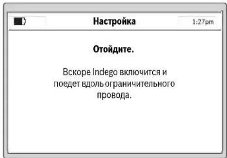
B Hnkeyka3aHHOM dHanoIe OTObpaAetc npBbIy 06be3d orpndtehboHnpoBOJOKn:
Korda caoobbHnHCTpymENT npBbI pa3 o6be3kaeT orpaHntelbHyIO pPOBOJOKy,HOHN He BpaAaOTcH.
YkaaHHe: PnKapTnpoBaHn Indego cneyert no orpaTntbHNo npOBOnke No Kpao ra30Ha. B MeCtax, rde npOBOIoka yXoDHT Ha paCtOHHN 1 Cm B HainpabJIeHHn ppeTCTBnH NnOT Hero, npOBOkA He pacNo3HaTeCN Indego cneyert aanee NO BHEWHeMy OrpaXdEHHIO. (cm.pnc.8)
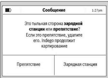
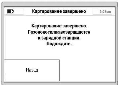
H3mepeHHe 3aBepHe,ecnCaIOBBHINCTpyMeHT DocTHTbIbHO CTOpHO b3apADHO CTAnu.

302 | Pycckn
HaKMMte ePpenTCTBne,ecnCaONbHnHCTpyMeHT He DOCTN TblbHO CTPOHO 3apdIOHO CTaHUN. Co6IOaIe HnHOFMaHIO HA dncnnee, YTObI 3abeepHTb HAcToPOky.
HaxMMte 3apnHaTcHua》,ecnCaOobbMHCTpyMeHT IOCTI TblbHO CTOpOHb3apHHO CTaHUN.

Iocne yceuhoH NaCTPOKn Bbl MoKeTe HaKaTb Kocntb, 706bl HeMeJIeHNO HauTaB KOcNTb TpaBy, HmCoCTaBtB BPemehHO rpaΦM B《Meno> N3menHeNr ppaKa》
JaIbHHeHuO HnFOpMaHIO O NoBeEHIN CaOpBOHO HnCTpyMeHTa PnCkAunBaHN TpaBb Bb HaJeTe B pa3dene CKaunBaHNe.
BbOrdpaΦnKa cKaunBaHn
CkohnhynpnyTe rpaNk ckaaHbAHIN HaCTPOHN B COOTBETCTBNN CNIHbIMN NOTpe6HOCTAMN.
Hnke noaHO np6bn3HeBpeMnHoro
CkaunBaHHa cada. PoKanyNCTa, yUTte, YTO 0To BpMa
BapbpyeTc B3AChmOCTn OT COtOraHHa nOT
KOnueCTBa oBeKToB HaRaOte.
200 m² 24
500m² 64
800M² 94
1000M² 124
1200M² 15u
Bce nyHKtb MeHIO npedCTaBHeBb B pa3dene «Tabnua nporpaMM».
BpeMeHHoIpaHKnIOaHReTcnoPpO6Ho.DpyrHe IyHKbI MEHO IOHHTbI camn no ce6e.
BpeMeHHoI rpaΦNK
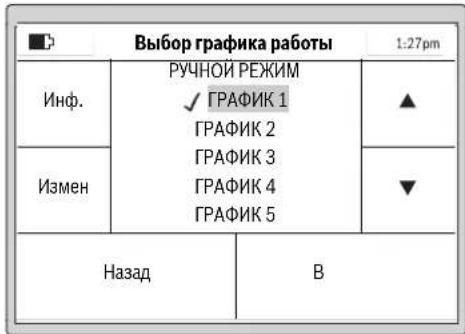
B«MeHIO>IV3meHHeIrpapKKaMOKHO Bbl3BaTb5 BpemeHHbIXrpaΦIKOB.
"PyUHONPEXMM" cIeNyEt HcNoIb3oBaT b TOM cnyuae, ecN caOdBb HnCTpyMeHT dIoJIkeH paBotaT ToIbKO B aKtyaIbHOe BpEMr.
KaJdbI KPAHMKMOKHO COCTaBbB CootBcTbHnC BaAMN Tpe6oBAHMAH.
PnMep:
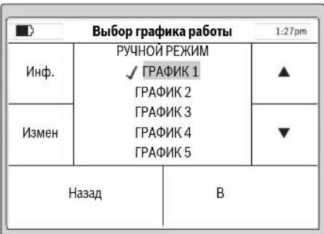
Bb6epHTe 《PFAOK》c NOMOJIbIO KYPcOPa BBepx/BHN3, HApN.,《PFAOK1》,HNAKMITEeH3MeH
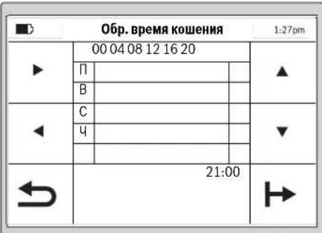
BbIbePte cooTBeTcByouu nnEh ckaaHbAHn TpaBblc nOMOuIbIO KypCopa BBEpx/BHN3, HApN, EIIb. BbIbePte BpEMHaayana CkaaHbAHn C nOMOuIbIO KypCopa BnPaBO/BNEBO.
IIOITBEPINTE BPEMHaayala CkaaHbHaNc NOMOsbIO KHOKN CNpaba BN3y.BbBepTe BPEM OKOHAnnCKAaHbAHNc NOMOsbIO Kypcopa Bnpabo/BNEBO. IIOITBEPINTE BPEMOKOHAncckaHbHaNc NOMOsbIO KHOKN CNpaba BN3y.
CaObBn HNCTpyMeT paObaTeB OBOHOM BpEmEHOM OKHe Do TEP NOP, NOA He BO3NHKHTNTopeBHOCTB NOp3aPdKe AKKyMylrTopHO bApEn. EcnI NIOuabJra3oHa Bydet CKOHeNo HCTeUHnBpEMEHOrO OKHa, CaObBn HNCTpyMeT BOSBpaAsaTcR KapdHOn CTAHm.
Pycckn303
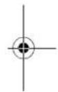
3anporpaMMPOBAHHbIe BpeMeHHbIe OKHa OTo6paKaHOTcB 063OpHOMIIaHe.
Hactpoite BCE DOONIHHTeBHO Heo6xOIMbIe HINCKaunBaHHN INOTBepNTe BaunHbIg「PAPHK1cNOOMbuKKNKnCBeBAHN3y.
YtObIyUdAInTbBpeMeHHeOKHO,NEpeMeCTHTe KypCop K BpeMeHHOMy OKHy UdAInTe erO npN NMOuIN KHNKN Cnpaba BHn3y.
Bo3ne coxpaHnHO BpeMeHHOro rpaHka nOBnEETcraNoOyKa.
Caoobib HnCTpymehaHuyET Kocntb TpaBy,KaT OtonkO HaCTyIHT DeHbHaJIo BpeMeHHCKaWbHAHH,3aAHHBe BO BpeMeHHOM OKHe 1.
YkaaHHe: 3aDaBaIte pa3nHbB BPemEHHOI rpaHKn C yETOM ce30OHbX Pa3NJH B PocTe TpaBb BEcHoi, NToTOM n OceHbO. HabNoTaIe 3a pOCToM TpaBb I NO Heo6xOHNOCtN npBOHIOI BPEMeHHOI rpaHKn B COOTBETCTNE.
CkaunBaHne
He pa3peuaiTe DeTMAKATAbCnHa caOBOM HNCTpyMeNTe.
PepennoHnem caoBoro Hnctpymeha 3pa yky dna nepehocaa hXMMte pyuhyo KhoNkY Cton.
BbICota cKaUHbAHnR: BbICOTy cKaUHbAHnR MOxHO HAcTPONTB nPpeJenAX OT 20 MM NO 60 MM (CM. PHC. 19). NMeETcR 10 pa3NHyBHX HAcTpoE (npHbN. 20 MM, 24 MM, 29 MM, 33 MM, 38 MM, 42 MM, 47 MM, 51 MM, 56 MM N 60 MM).
YkaaHHe: CnCTema HoKeJ Indego npedHa3aHeHa dIra CKaunBaHAnKOPOKToI TRpaBb (3-5 MM).CKoUeHNa TRpaBA MOKeT OCTaBaTbCa H3eMBe B KaueCTBe MylbuNd IyObopeHra3oHa.
Yka3aHHe: B TeueHHe nepBbX 3 HeDn b yCTaHabNBAitte BbCOTc KaunBaHnB A B pndenax MEKdy CTyneHbO 5 n MAX, T06b He Nope3aB orpaTneBHyIO npobOnOky. Upe3 3 HeDnnpOBONKa ByET NOKpBtA r3OHoN.
CoCTABNITBEpeMeHHoHrpadKcactbIMNOBTOpeHHM.
BnaOapraTOMy BbyIOCTINHTe xopoWnXpe3ynbTaTOB
CKaunBaHHa,3apAKn AKKymIaTOPH6bATEHN XbHTHa
DOnbweNy BacHa ra3OHe 6dyet pa3bpcAHHO TpaBBi.
Nocne hauana ckaunbHaHnA:
caobBbHCTpyMeHTpa0TaETBpeXHMpePYHOPEKHMDoTeXnop,NOKA OH HE BbIKoNTnIOaadbaTOnaHnOKA BbI He HaxMeTe KNKONCTon. CkaINBaHne npebBaTcToTbKOHe 3apJNkAKkyMnyTota.
caobbHnCTpymehpabotaetHenpepbBHO B nporpaMHHpyemom pexHMeAaPbHKBnpenax 3aHaHOro BO BPemEHOM OKHe BPemEHORIO INTEBana. OH npepbBAeT cKaunBaHne ToNkOJI 3apRKn. 4ro6bl npepBaIpooccCKaunBaHnOIO hCTeHenn 3aHaHORO BO BPemEHOM OKe BPemEH, HaxMHTe pyHyIO KHONK Cyton.EcnPioudaBra0ha6ydt CKouHeAoIO hCTeHenn 3aHaHORO BO BPemEHOM OKe BPemEH, Caobb I nCHTpymehBO3BpaAaETCA3apJHO CTAHIN.
3ΦΦeKTHBHOe cKaUHBAHne c Logicut
3ΦΦeKTHBHOCTbCKaUmbaHnIndego (cm.phc.20)
IIN300EeKTHBHO CKaUHBAHH INdego Hcyaet FOpMy NOBepxHOCTH, HA KOtOPOH OHa paBoTaET. IPOuEnypa bIObuyehn OcUyecTBeTcRc BO BpEmpePbByTxpaOouNX uKlIOB.
Jaee noaetc onHcaHne toro, kak Indego H3yuaet fOpMy r30Ha.
PpHnnpa6oTbI
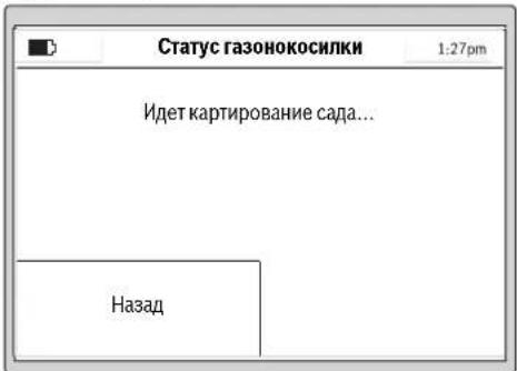
IINH30000000000000000000000000000000000000000000000000000000000000000000000000000000000000000000000000000
KapthpobAHne pa6ooyero yuactka (cm. pnc. 20)
Iocne hactpoikn Indego B nepbB pa3 Kaptnpyet BheuHIO FOpmy caa. 3To npOnxOHT BO BPMe 6bEzda ORpaTHeBHO npOBOKn, npTOHYtoN NO KpaIO ra3OHa. Bo BpeM o6Bezda Indego H3MePReT paCtOTHN, rHePpYeT kAPty n coXpAHReT ee B CboE nnAMr.
Yka3aHHe:Indego He cneJeT no npOBIOKe K BHyTpEHNM orpaJDeHHM.
304 | Pyccknki
H3yueHne nonoXeHHn oropoxHeHbIX npoBONOKo 6beKToB BCaY (cm. pnc.20)
Kak tonbko Indego 3abepint KapthopobAHne yuactka nIyckaaBHAAHnO, OHa MoKeT Hauayt CkauINBaHHe. Nocne haxaTHHa KhoNkY (Kocntb) Indego Bae3Kaet C 3apdHoi CTAnHHu HauHnaeT Kocntb Tpaby NapbIeBbHMNoJocamn. DmHa napaJIeBbHx NIOc oOrpaHueHa np6n10 M, YTO6bI obecneHTM MakChMaHbHO TOUHO cOBIOJeHNE NOcBi rAOHOKOcNIOK. YAcTHCuHbYCACTOK o6paBATbAeTcra npaJIeBbIMn NIOcAMn, eCN ToIbKO rAOHOKOcNlKHe OBHApuyKNT oBBeKT, orOpoxeHHbOrapAdTeHN npOBONoKoN.
PnOsbHApUeKHeN TAKoT OObEka Indego CneJeYeNo
OrpaTeNbHO npBOOnKe BOKpyr obekTa dIa
pAcno3HabAHn erO fOpMbI. DnIOIbTBePckDHeHH
NOJoxEHn OBekTa Indego eJET K Kaio Ra3OHa Do
OrpaTeNbHO npBOOnOKn H 3anOMnHaet MecToNtOKeHHe
Ha KapTe cada. 3aTeM Indego npOdoJaAe tCKaUNBaHHe.
Piocee NOBTopReTc, ecn BO BPema cKaunBaHHa InDego
BCTpeAaHOBie ObEkoBt. OKOHnB pAOy, Indego
Bo3BaPaauTcRa Ha 3apdHyO CTAnuHIO.
Yka3aHHe: 3Ta npOeIpya nobTOpRcTc npn BTOpOM
CkAaBHaHH. TaHKM o6paON pOBepReTC, BCE nI OBeKtbl
HaJIeHb C aCy I N MeCTOnIOKeHr Ha KapTe cada
HadeXho 3anpOTOKoINPObaHI.
Ecn npynx obektoB cahy he ohabpyxho, Indego npoIOnKaet ckaunBaHne B HopMaIbHOM peKHe.
Ecnn nocne 3anycKa B ekcnnyatauHno Heo6xOJHMO oropodntbdoonNHtBHyIO npouaIbB HHTpyCada (Hanp. kynmy), MoKHO doabNt bdoonHtBHyO orapadnblHyIO npOBONKy pnpomoN Ka6bHoro coeHNHTnra. (cm.pnc.10)
PexnckaunBaHHa (cm.pnc.20)
KaTToBkoIndegoN3yHTNOJKeHHeO6BeKTOBBCaNy,OHa 0fFekTHBHO KOCHT RaOH NapAJIeNbHbIMN NOLOCAH.
Pe3aHHe c ydBoeHNo CKOpocTbIO
EcnB0BpeMaCKaunBaHnIndegoBCTepeaet BbICOKyHnn TOnCTHyTPOABy,rAHOHOKoCNHa ABOMaTHeCKN yDbaHaeB OOBpOBy CnCTEmbPe3AHn HCHKaAeKcKOpCtB nepehKnHKeHH,NOKA tO MeTO He 6yDte CKoUHeo.
CkaunBaHne no KpaH
B 3OM pexHMe Indego KocHT BDOJ ORpaHTeNbHO npOBONIOK, YactOry MOXHO HacTpaHBt. B 6a3oBbX HactpoKAX TAKOE cKaUHBAHne yCTaHOBNeHO Ha KaXDbY qteBptbI pa3.
Haxnct nonoc ckaunBaHHa
Indego Kocnt raoh npapannbHbIMn HHHMn DHHHO 10 M. PaccToHHe MeJy HHHMn PpeDyctaHOBNeHo Ha 20 Cm, Ho pNp BbcokOnTrabe Oho ABTomatueckn yMeHbAetc. NocIe cKaunBaHnT TaBbl paOta npoONJaTaC n CYaHOBneHbIM pacCToHHeM MeJy nONocam. NpNo3BaTeB MoKet H3MeHnB 3Ty HactpoKy npn NOMU MeHIO.
aTukn
CaOobBb HnctpymEn OCHaueH HxkeyKa3aHHbIMN DaTnKAMN:
-ДатчнлобemaakTNBnpyeTCHNOTKIOUaETPNHBOH HOXINIOHHTNHCAOBOROHCTPMEHTA.
- DAtuKOnpOKnDbIbAHnPaCnO3HaETnepeBOpaHbAHHe CaIOBOrO HNCTpyMeHTA HNKeH CTopoHO KBePxy N OKIIIOaET PIPBOD IN HOXN.
- DataHk 6nokpOBKn paon03Haet npHKoCHOBHeNKe InpaTCTBHO B IpeneJax UipHHb KOHe CaOBoI OHCTpyMeHTa HINuMpyET CmEhy HanpaBHeHn.
- DAtuHK HAKNoHa AKTHBnpyeTc,ecnn caoobblnHCTpyMeHT DoCTHraeTyrna 45.
Ecn OIN N3 DaTnKOB AKNBpyTeC, HAp., DaTnK NOIbema, Ha DCNlnee NOBnBnTeC CoO6eHHe: «CaOobbl HHCTPYMEHT PNNODHRT. BBeNTe PIN-KoD, YTO6bI IPOJOLNKTb CKAHNHE. ECN HA pOITRAKeHHN 10 MmHYT He 6yDe T BDOHtCBa HNKAKHX DAHNBX, DHCnNE NEPExoNDt B COCTOHBE NOKOR. YTO6b CHO BA AKNBnPoBaT DmCnNei, HAXMITE IIO6yo KHOIky.
EcnI CaOBMy INHCTPymENT HAXOHTC B COCTOHN NIOKOR, HAKMNTe IIO6yHO KHOIIky, YTO6bI Bb3BaTb 3KpaH DnB BBOda PIN, IN BBeINTe PIN-KoD.
3apkaakymyntopa
AkkymyIaTOpHaa6ataperaOchaueHaDaTuHKOMKHTPOI TEMepaTpbl,DOYCKAIOUHM3aApIKyTOIbKO B TEMepaTpHomDnana3oHe05Cdo45°C.
HHTHEBO-HOHNAKKMYIANTOPHA6baperaNOCTABINETCA qaTHMQHOZAPAAKEXEHNO.HTo6bIOCTNUNHOEMKOCNT AKKMYIANTOPHO6bapen,NEpeI NpBBMNCIOJIb3OBAHNEM caOBbHnCTpyMENT HeoBXoDMNO NOnHOCTbO 3apADITB 3apADHO TAHCN.
HINTHHOHHbIaKKyMnTOpMOKet6bITb3apXKeB HIO6OBeBpMa6e3cOKpaueHcPOKa cnykbl.1peKpaueHne npoecca3apRKnHeHaHOCTBpdaakKyMnTOpY.
Pn caaueeHnn pa3pKaeeHHo AkkymIATOPHO 6batape caoBbH NcTpyMeHT BbIKIOyaeTc 6bIarOapr CXe me 3aunBt: HoXn 60bnE He DnraKOTc.
Pycckn305
Ta6nua nporpamM
BHHkeyka3aHbTx Ta5nuaX noCHHOTcpa3nHbIe IyHKtMeHO.
www.bosch-garden.com
PnB Cex DoonHnTebHbix Bonpocax 3aKa3e 3aNacTcE, noKanyIcta, 063aTeBHO yKa3bIbAte 10-3HaunHb ToBAPHb NHomeP, yKa3aHHb Ha 3aBodcko TabnHKe caDobORO HmCTpyMeHTA.
Ecn HeoXOJHMO OTnpaBnTpo60THIPOBAHNYO ra3OHOKOCHNky B cepBnchbl CEHTp Bosch, BcERda OTnpaBnIe BmecTe C HeTakKHe 3apdHyO CTAnHIO.
DOnONHHTeBHO Heo6xOJMo yKa3aTb BepCNo HnOpyAMMHorO obeCneHeHH BaUero caDoBOro HnCTpyMeHa (CM.«MeHo> HAcToPouKn > ChTeMhBe HaCtoPouKn >HnOpOmauN).
Ди рснona: Pocn, Genapycb, Kaazctan, YkpmaHa
IpaHTHnHoe 0cbnyKbAHHe HpeMOHT 3neKtpOnHCTpyMeHTA, CcObIOHeHM Tpe6OBaHHN HOPM HtOToBHeTl IPOn3BOaTCH Ha TePPNTOpHN BCEx CTpaT OToBko B DmPmEHbix Nn ABTOp3OBaHHbx CepBnCbHx ueTpax PObepBoi.
PNEUYPEKDEHNE!NcnoIb3oBaHne KOHTpaKaTHO npOdykun OnaCHO B3KcPiNyatauHN,MOKeT pINBecTH K yuepebyna BaWero 3dOpobBa. HrrotOBHeH paacnpoctpaHHe NKOHTpaKaTHO npoDykuH npcepeyeTeCn o3aKaHOY B aDMNHCTpTaHBOM H yroLoBHOM noRJaK.
Pocchra
yolHOMOueHHa H3rTOBHTeNEm opraHn3aunr:
000PobepBow
BaiyTHHCKoe WOCCe, Bn.24
141400,r.XHmK,MockOBcka86n.
Poccn
Te:88001008007(3BOHOKnoPocnn6ecnnaTHbI)
E-Mail: info.powertools@ru.bosch.com
POnHyIO AkyIaLyHO HnOpMaHIO O pacNONoKeHHN CepBCHXZIeTHPOB INpHEmHBx IyHKTOB BbMOkeTe NONYHTb:
-
Na opduhnaBHom caIte www.bosch-pt.ru
-
n6o no TenefoH cypaBOuHO - cepBnCHOH cnYk6b
Bosch 8 800 100 8007 (3BOHOK NO PocCNb6cNnAthB)
Benapycb
HIN P06epBouO OOO
CepBnChbI ueTp no 6cbnyKbaHIO 3neKtpoHCTpyMeHa
yn.Tumnpu3eBa,65A-020
220035, r. Mmck
bentapycb
Ten.: +375 (17) 2547871
Ten.: +375 (17) 254 79 15/16
ΦaKc: +375(17) 2547875
E-Mail: pt-service.by@bosch.com
Bo3MOXHbI H3MeHenHHa
YkpaHcbKa309
YkpaHcbKa
BneBHitbcra, 0c aobn iHCTpymEnr He 6Iokye H He 3aropoJxye BxOOn.

PonepeJxehn: PpOHTaTe IHCTpyKciIO 3 ekCnIyataci, nepH HIX BMkATn CaOBn IHCTpyMeHt.

PonepeJKeHHa:BmKHiTb caobn iHCTpyMeHT, nepH HIX BHKOHyBaTH Ha HbOMy RaICb poBOTn a6oPiHIMATn NOrO.

Obepexho: He TopkaTecsdo hoxib, 0o o6eptaotbcra. Hoxi roctpi. Bepexitb nabci pyk i Hi!.

Iepsh Hix TopkaTncdO
TeTanei caIOBOrO
IHCTpyMeHTy,3aueKaIte,DOKn
aJI He 3yINHrtbcN.Picra
EHHa caIOBOrO IHCTpyMeHTy
Je npoIOBxUOTb OepeTaTnci
bpni3BeCTn Do nopAHeHb.

CniKyIte 3a Tm, 06
yJxopiHi yactKn, 10
BIDnIraIOb npn BVnuBaHHi
NOBITpR, HeTpaBMvBaHIOJe
no6n3y.

IonepeJxehn:
DotpmyTeC6be3neuHoi
BicTaHI DO caIOBOrO
MeHTy, KOIN BIn npauoE.

He KaataItecHa caIOBOMy IHCTpymEnTI.

3apHn npctpi 0bHaHn 3axncn m TpaHcOpMaTopoM.
D□C
3HIMHH 6LOK KINBHeHH. He BnKOpNCTOByIte IJn YuueHH po6Otn3oBaHOI Ra3OHOKocapKn OUnSyBaU BnCOKOrToNCky a6o caIOBn ShaHr.
Ekcnnyatauia
- Ppeed BHKOHaHHaM 6yDb-aknx po6it Ha caobomy iHcTpymenti (Hap., nepeed texo6cnyroByBaHHaM, 3amHOIO po6ouh iHcTpymentiB too), a TaKoX nepeed TpaHCnOpTyBaHHaM i 36epiraHHaM 3HimaTe nepeepHBau cTpyMy.
310 | Ykpaɪhcbka
HikonHeO3BOJnTe DIaM a60OCo6am, kI He 3HaJOMi 3 cHMN Bka3IBKaMH, KOpNCyBaTHcAcdOBm iHCTpymeHTom. HaiohaJIbHI npnnnc MoKytb obMeKyBatn Bk OepaTopa.
Ley caobn iHctpmHT He np3HaueHn dIy BIKOpNCTaHHO c6amn (BKNUaOHu Dite) 3 06MeKeHmN nCHxiuHmN, yTcBHMn a6o pO3ymOBHMn 3dAthOCTaMn a6o HeIOCTaTHIM OcBiOM Ta/a6o HeIOCTaHIMN 3HaHHMa -e Do3BOJAEbCp PObTHn IInse y TOMy BNpaIKy, kUO 3a HmN CNoCTepiraoc Oc6a, zo BiIOBIAc 3a ixHIO be3neky, a6o BOHN OTPMUYOT BiI Hei BkazIK NIOTOrO, kCnID BHKOPNCTOByBaTH npnaI.
Heo6xio hO cnoctepiratn 3a dIbMn, 06 nepekoHaTncs, 00 BOH He rpaIoTB 3 caOBm IHCTpyMeHTOM.
KopntyBaH Hece BiINOBiJaBHiCTb 3a HeuacHI BnnaKn, TineChi ykoJKeHHI HnIX IIOeI i NOkOKeHHa YXKO MaHa.
JHKIO nIac eKcnnyaatai caoBoro iHCTpymEnTy BHHKnIaKi-He6yDb He6e3neKn, HeraHHO HaTNCiThb Ha cepBOHy KhoNkCy CTOn.
POn6aTe npo npaBnIbHe npOKlaHaHH orOpOJyBaIbHOdpoTy 3iINHO 3IHCTpyKciEIO 3 ekCnIyataui.
-NepeBiprIe oropOxyBaIbHn IpiT.BiH NOBHeH 6yTu HAraHHeHn IO BcIM IOBXNHi,3aKpIJIeHn Ha 3emNi KINOuKaMn i He npOBncATn IETJAMn.
Perynpho nepeBipny Te iHky,Ha KIK BHKOPNCTOBYcTcABOBIN IHCTpyMeHT,IBdAJIyTe KaIMHHa NaKN,dpTN INHI CTOpOHNIpeDMETN.
He nepeixkkaite uhypn knbeneHHa 3haxoJbTc nHapyroIO.
Perynpho nepeBiprTe caOBH ihctpymeHT, 06 nepekoHaTncb B TOMy, 00 HIX, rBNHTn HOxai p3aIbHn anapat He 3HOseHi I He MAIOb NOIKoDKeHb. 06 yHNKHytn Dn6baHcIB, 3amHIOte Opa3y Bci 3HOseH HOxI rBNHTn HOXIB.
HikonHe BnKOpHCTOByte caOBn IHcPymENT 3 N0wKOJKeHNM 3axnCHMN KpnShkAmn a6o 6e3 3axnCHNX pncTpoIB.
He niicobuyte pykn i HOrn nidetani, 0o oBeptaotbcra, i He Tpmaite no6n3y BiTaknx Detanei.
Hikonn He niHimaiTe i He nepenocbTe caobni INCTpyMeHT, KOHN pauioe MOTOp.
Caobn iHCTpymeHT He NOBHe npaObaTn 6e3 Hargny, kIo Bn 3HaTe, IIO NobIHy 3hAxoJrbcn DomaHi TBapHH, iITn a60 iHwi JIOH.
BmkaTe caOBn IHcTpymeHT 3iINHO 3 IHCTpyKciEIO 3 EKcnnyatauii I DToPMMyTecb 6e3neHoi BiDCTaHI BID DeTanei, IO oBeptAioTBca.
He BnKOpNCTOByTe caOBHInCTpyMeHT OJHOuacHO3doUyBaJIbHM anapaTom. CkIaJaTe rpaΦik dIy yHnKHeHHaOHOuacHOi po6To nO6x cnCTem.
YkpaIHcbKa|311
HiUro He Minrte B npnadi. Heo3B0JIeHI 3MiHN MOxytb BnHHyTH Ha 6e3neKc CaOBO rIOCTpyMeHTy i np3BecTn DO nocHHeHX WymiB i Bi6pauiN.
BiDmKaiTe po3'eHyBaU cTpyMy:
- npeed TM, JK 3BilbHHTN UHHN UO 3actpnn,
- npeTm, k nepeBipHTn a6o npouHCTHTn caOBn iHCTpyMeHT, a60 BHKOHATN kICb po6OTn B HbOMy,
-yBnnaKy He3BnuaHoi Bibpaui caIOBOrO IHCTpymEnTy (3ynHITb caOBnIHCTpyMeHt I HeraiHo nepeBipTe Horo), - nicra 3iTkHeHHa 3i CTOpOHim npedmetom. Ipebeipnte caobn IHCTpymeht ha HABHictb NOsKOJKeHb i 3BeptaHTeca DO cepBicHOi MaNcTePHi Bosch dI npoBeDeHHa Heo6xIDHX peMOHTHX po6it.
Texhiue 06cnyroByaHHA
BdraTe 3aBXn caObi pyKaBnci, KaIO Bn 36npaTecb opyBaTH a6o npauOBaTH no6n3y roctpnx HOxIB.
- Ppeep npoBeHnM 6yDb-aknx po6it hcaObomy iHcTpymenti 3himaiTe nepepmbau ctpmy.
Ppeep npoBeHnM 6ydb-aknx po6it Ha 3apAHH CTanu a60 6noci XNBHeHH BHTaryTe wTencelb 3 pO3eTK.
PeteBHO OuyuYte 3OBHiuHIO NOBepxHIO caoBOrO IHCTpyMeHTy 3a DOnOMOrOIO M'AKOI uITKN I raHupKn.
He 3actocobyte Bovy, po3uHHNKi nonipybalhi 3ac06n. BnuIaIne BCIO npHInny TpaBy i3a6pydHeHHN, OcO6lnBO 3 BEHTnlaicHHx ciHH.
Perynpho Ouyuye 30Hy HOxIB,Ду Yoro Tpe6a nepeBepHytn caIOBn IHCTpymeHT HIXHbOIO CTOpHOIO Doropn. BkOpncTOByte TBepdy UITky a6o ckpe6ok dny BndaJIeHHa 3pi3aoI TpaBN, 1O MlCNo pHInnna. (DINB.MaI.A)
Hoxi moxha nepeBepTaTn. (INB.mal.B)
- IpebeipnTe Bci raikn, nporoHnui I rBnHTn Ha npedMeT miuHOi nocaKn, uo6 3a6e3neuHTn 6e3neuHn po6ouH CTah caOBOrO IHCTpymEnTy.
Perynpho OOrJaAnTe caOBH IHCTpymEnI 3apaNn BnaCHOI 6e3neKn 3amHIOte 3HOWeHi N OOWKOJKeHl Detani.
CπiDkyIte 3a THM, uO6 BnKOpNCTOByBaIINc IINHe OpiHInbHi 3aIpaCTnHn Bnpo6HNTBa Bosch.
3a Heo6xHocI 3amHIOte HOKIN TBHHTN YcIM KOMnEKTOM.
36epiraHHa Ta TpaHcnpTyBaHHa B3HMky
Ipeed BCTaHOBHeHHm caOBOTo IHcTpymEnTu Ha 36epiraHn 3HimaTe nepepBauchtpymy.
Ta30Hokocapka Indego npn3NaheHa dno p6oTn 3a Tempepatyn BiD 5°C Do 45^ .B3nMky, konI Tempepatya npOTAROM TpHBanoRo yacy TpMaetbcn HxKue 5°C, 36epiraTe
312 | Ykpaɪhcbka
Indego i 3apAHy cTAnciy HeIOCTyHOMy IJIaITei,HaINHOMy icxomy Micui.
He cTaBte iHsi npEmdTe Ha caObH iHCTpyMeHT a6o 3apAHy cTaNIO.
Ipn TpaHcnpOpTyBaHHi Indego Ha doBri BiDCTaHI HauKpaue 3a BCE BnKOpNcTOBvBaTH OpRHaJIbHy ynaKOBky.
Kapta nam'arTi SD
IHTeppeicnSD-Kaptny
po60TH3OBaHIN ra3OHOKocapci
np3HaueHn BKNIOUHO nn
DiarHOCTHKn IporpaMHO
3a6e3neueHHy cepBichOMy ceHTpi Bosch.
He6e3neka uepe3 akymyIaTOpHy 6aTaPeI0
3apJxHnHeo6xidno 3iINCHOBaTHnIWe yDOnyUeHiI fipMoIO Bosch 3apJdHi CTanii.
Indego npaioe npn temepatypax BiD 5°Cdo 45°C. Jkto Temnepatypa akymyIaTopa BHXoNDt b3a Meki zuBOrO dianazOnHy, Indego nobiOmne npo ce Ha CBOEm yinCnIe i a6o 3aIIuacTbcaHa 3apAHi CTanui, a6o npinnHcpo60ty i NOBepTaecbHa 3apAnHy cTAHIO.
YHnKaIte KOHTaKTy 3i CaIOBm IHCTpyMeHToM, AkiO y HAn3BnuaHnCITyaui 3 akymyIaTOpHOi 6batapei BNTiKa e piHa. Y BnauKy KOHTaKTy 3 ciEIO pIDINHO 3BepHITbc DO IkaPra.
AkuO aKymyTOp nowKOJKeHO, pINHa MoXe BNTeKTn i NOTpanHTn Ha cyciHi detani. IpebeipTe detani, ha
Kni Notpannna piHa, i 3BepHtbcn do cepbichoi Maictephi Bosch.
He po3kpBaIte caIOBn IHcTpyment i akymyIaTOpHy 6aTapeIO, 0o 3HaxOHTbcn BCEpeDHI HbOrO. IChye He6e3neKa KOpOTKOrO 3aMnKaHHN ypaXeHHN eNeKTpHNM CTPyMOM.
3axnauTe caobn iHCTpymeHT BIDBORHIO.IChyE He6e3neKa BV6xy.
Ypa3i nowkoJxHnHa HehaIeXHOro BHKOpNCTaHHaCaIOBOrO IHCTpyMeHTa MOxJIHBO BnDIneHHa napu 3akymyTOpHO6aTaPei.3a6e3neuty npnnHB CBIXoro nobITpy i 3BepHITbcdo NiKapA, KxOcCKaprHa CTan 3dopoB'.BdxxAHHa napu MoKe npn3BeCTn DO NOpa3HeHHaNXaJIbHnx IJIAxIB.
36epiraTe caOBn IHCTpyMeHT nHne npTempepatyPi BID-20°Cdo 50°C.Hanp.,He 3aIIuAte caOBn IHCTpyMeHT BlITky B MaunHi.
Bka3iBkn 3 Texhikn 6e3neKn dny 3apAnHoro npncTpoio i 6noka XNBHeHH
3apJxHHeo6xIDHO 3iINCHIOBAtnIhWe BOpriHaIbHi 3apJHn CTAnuBnPo6HnTBA Bosch.BInOMy BnAky icHyec He6e3neKa Bn6yxy i noKexi.
Perynapno nepeBipnte 3apnHy cTanuio,6nok XNBnHn, uHyp i wTenceIb. He BnKOpncTOBynte 3apnHy cTanuio a6o 6nok XNBnHn y pa3i x noXKOJxHnHe. He po3KnBaTe 3apnHy cTanuio a6o 6nok XNBnHn caOcTiHo,ix
YkpaHcbKa313
peMOHTdo3BOJeHO BVKOHyBaTH
Hnwe KBaniipikOBaHOMy
nepcohanyi nne 3
BHKOpncTaHHm opnriHaIbHNX
3anuactn Bosch. NowKOxKeHH
3apraHoi cTahui, 6Noka XNBHeHH,
shhypa XNBHeHH a6o WTeNCeY
niDnUyIOb pN3NK ypaKeHH
eNEKTPnuHm CTpyMOM.
He BHKOpNCToByTe 3apAHy CTaHciO i 6nok KHBneHHa Ha IerKo3aMnCTi NOBepxHi (HaNP., Ha panepi, TkaHHax Too) a60 no6n3y naIbHNx MaTePianIB. Upe3 HarpBaHHa 3apAHOi CTaHci I 6noka XnBneHH nI yac 3apJXaHHa BnHkAc Hebe3neKa noXeki.
▶YBara:Дяплдзарджаннбатаepi BHKOPNCTOByTe JINWEdoHaHOro 3HIMHOro6LOkyJKNBHeHH.
ДИВITбЯдьм.ДITи He NOBHHI rpaTnca i3 3apdHIO CTaHciIO,6LOKOM XINBHeHnA bO caOBm IHCTpyMeHToM.
Дитам ta oc6am,як BiHacniodok ypaXeHHaI3nHnx,ceHCOPHX a6o po3ymOBx 3di6HOteu CH BiCyTHOcTI DocBiy a6o 3HaHb He B cTahi 6e3neUHO npauIOBATn i3 3apAHOIO CTAHciEIO a6o 6NOKOM XNBLeHNH,3a6OpOHCTbcr KOpHCTyBaTHC3apAHOIO CTAHciEIO I 6NOKOM XNBLeHNH 6e3 Harny a6o IHCTpyKtaxy BiNoBIaIbHOi OC6H. IHaKwe MOKJIINBE HenpaBnIbHe BVKNOpCTaHH Ta He6e3Neka OdePkaHH TpaBM.
Hanyra Bdxepeni ctpymy noBHHa BiNobiataHaHnMa 6noi XNBHeHHa.
B ideaHbHomy Bnapky 6nok KINBHeHH NOBHeH 6ytN iKIOeHN dO PO3eTK, kA Ma e npIcTpi 3axnCHOro BmKHeHH (RCD) 3i ctpymCnpaIOBaHH He 6Inbwe 30 mA. Perynpho nepeBiprTe cyHKioHaJIbHy 3dathictb npIcTPO 3axnCHOro BmKHeHH (RCD).
Hyp Heo6xiopeyraHpo nepeBipTnHa HABHCbO3HaK NOKDKEHH,NOO O3BOJcBcB NKOpNCOByBaTHNHe y 6e3dOrAHOMy CTahi.
3MeTOU yHnKHeHH He6e3neKe np 3aMIHI uHypa XNBHeHH 3BepHiTbcra Do Bnpo6HnKa,BAbTOPu3OBaHy cepBICHy MaNCtepHIO Bnpo6HnKa a60 Do KBanlipKOBaHO qaxIBz.
Pn3amini shhypib 3apraHoi ctaHuii 6noka kHBneHH cnikkyte 3a Tm, 06 BOHN bynn D03BOHehi fipmoo Bosch.
HikonHe 6epitbc3a wTeencelb MOKpMn pykamn.
He nepeixkjaKe, He 3daBIOHTa He CMnKaIte MepeXHn UHyp, OckInbKn TAK NOrO MoXHa NowKOHTN. 3axuauTe uHyp BiD BnCOKoi TEMpepaTyPi, Macna i FOCTpNx KpaIB.
314|YkpaHcbKa
3MipkyBaHbTexHikn6e3neKn6Iok XnBHeHHMa 3axnchy i3oJauio I He notpe6y3a3emHeHH. Po6oa Hnpyra cTahOBHTb 230 B\~,50 Tc (IJI KpaIH, 1O He HaLeKAtb Do EC,B 3aJeXHOCTi BiD BVkoHaHH-220B, 240B).InOpMaIO MoJHa OTpMaTH B aBTOpN3OBaHH cepBicHi MaICTepHI Bosch.
Pn cyMHiBax 3aHNTaHTe KBaJIΦIKOBaHO rEKeTpNka a6o Na6bIHXue npeCTaBHnTBO KOMNaHI Bosch, 00 3dINCHoe cepBicHe o6cnyroByBaHHra.
Peynepno nepeBiprIte MepeKHH
HHP Ha HArBHCtB BNDIMNX
NOxKOJKeHb Ta 03HaK CTapIHHH;
BNOPcTOByTe IHNp NIIe B
6e3DorAHHomy CTAHI.
CHMBOLN
Hactynhi cHMBONI cTahytB Bam y haroDi, kOni Bn 6ydtene. uHTa T aioo3OzMyTHN IHCTpyKIO 3 ECKNlyatau. 3anam'raTte CI cHMBONI Taix 3aueHHN. IpabINbHe pozMYMIHN cHMBONI BOJOMOKe Bam npABINbHO Ta 6beNEHNO KOpNCYBaTHC aDOBm IN HCTPYMENOM.
CmBbON3aueKnn

BdraIte3axnci pykabu

D03B0Jena

3aboponeHa

Ppnaanda/3anuactnHn
PpH3HaueHH npHnaDy
CaOOBH INCTpyMeHT npH3aueHHI JnKocIHHa raOHIB B npBaTHOMy roCnoapCTBI.
TexhiHi daHi
TexhiuHa Dokymehaia (2006/42/EC, 2000/14/EC): Bosch Lawn and Garden Ltd., PT-HG/ENS-PA2, Stowmarket, Suffolk IP14 1EY, England
Henk Becker Helmut Heinzelmann Executive Vice President Head of Product Certification Engineering PT/ETM9

Robert Bosch GmbH, Power Tools Division 70764 Leinfelden-Echterdingen, GERMANY Leinfelden, 27.10.2015
IoRcHHeHHdoMaHIOHKiB ⅢODo yCTaHOBKn (DnVB. cTOp. 3-14)
HaHCHiB 3apnA hctpyMeH iWOBdoTmboHO60kyapnoiCTau
320 | Ykpaɪhcbka
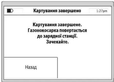
P03KnaI
YnykntiMeHIO>Bn6ippo3KnadyMOKHa0paTn5 po3knadB.
《PyH PEXHM》Heo6xIDHO BOKOPCTOByBATN,AIO caOBOH IHCTPYMEHT NOBHEN IpaOBAHT NIIeYIPOUHN yac. KOHHN PO3KIAI MoXHa CKnactn 3a Notpe6oio.
PnKnaI:
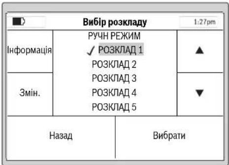
06epitbP03KnAD 3a donomoroo kypcopy Bropy/Bnna, Happ. P03KnAD 1, i hatnchitb 3minntn.
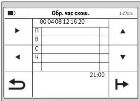
IicnycniHoro HanauyBaHHaMOxHaHTCHyTH KocnTH,uO6 noaTH KOChTtpaby HeaH0,a6o CknaCTn po3Knad BnyKTI MeH0>3MiHa po3Knady.
IpoaIbwaIHΦopmaJINpOIIcAIOBOrIHCTpyMeHaI pNCKoWByAHHi TpaBN3hAxOHTbcr y po3dNi(CkoWByAHHn
BbeHnpo3KnadyckouyBaHHa
3KoHphiIpyyIePO3KaIcCKOswyBaHHHaHaaWtYBaHH3rIdHO 3OC6bHCTMMNIO6aKaHHMa.
HnKue npDnHa np6bn3Ha TpBnAicbpoBt nAn NOBHorCKoWyBaHHa Cady. ByIb Iacka, Bi3bMitb Do yBarn, 10tpBnAicb poBto Moke BapIOBATmCB 3anEKnOCTi BID CTAHy RaOny i KInbKOcti O6'KTIB Ha HbOMy.
| 200 M² | 2 roD. |
| 500 M² | 6 roD. |
| 800 M² | 9 roD. |
| 1000 M² | 12 roD. |
| 1200 M² | 15 roD. |
Yci nykTHMeHIO npdctabnehi ynykTIaTabnua nporpamBBeDEHHApo3KnayNORCHHOETbCDAOKNaIHO.1HNIyHKMeHIO 3po3ymini 6e3 norcheHB.
06epitb 6aKaHn DcBckOswBaHH TaPbN3a Donomoro H Kypcopa Bropy/BnH3, Hanp., 06epitb cac Noatky 3a Donomoro H Kypcopa Hanpabo/Hanibo.
IITBepBteacnoatky3aDOnOMoHO KHONK BH3y npabopyu.OBePbTcac3aeBepWeHH3aDOnOMoHO KHPcopa HnpaBO/HanIO.IITBepBteac3aBepWeHH3a DOnOMoHO KHONK BH3y npabopyu.
CaoBn IHCTpymENT npaOe npotrrom nepworo npomixky
cayy Do TNX pIP, NOK He BNHHKHe NTpeBa y 3apJxAHHi
akymnTropHO batapei. IaIO nIOuA ra3oHy bye cKOweHa
do a3iHNHEHnI pOMIXkY cacy, caOBn IHCTpyMeHT
NoebpTaETCB DO 3aPdNHO CTANJI.
3anporpamobahi npomixknu cacy bio6paKaIbcy ornaIOBOMy nanaHI.
YkpaIHcbKa|321
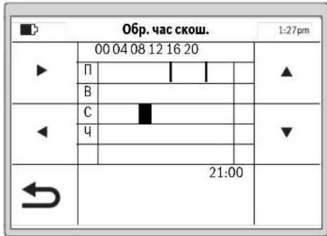
HanauTyIe BcI dOaTkoBHeo6xHdHdiCKoWyBaHHi iNITBePbTe CBHOC6nCTHn P03KlA1 13aDOnOMoHO KhoNNBHN3y libOpuy.
IbnananeHn npomixky aacy nepemictb kypcopdo npomixky acyi BNdanitb Horo 3a donomorIO KNONKN BHN3y npabopyu.
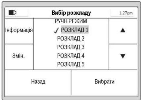
Bin36pekeHOro po3Knady 3'ABNTbca ranoyka. Canobn IHcTpymeHT noue KOCHTN TpaBy, AK TInbKn Hactahe deHb i ac NoaTky CKOswBaHH, uO ybeHdI dnn npomixKy aacy 1.
BkaibKa: HanaToBye pi3Hpi 03KnAa3 ypaxyBaHH ceoHNHX BiIMHOCTe npOCTI TPAH HBeCHi, BNITky I BOCEH. CnoctepiraTe 3a poCTOM TpABn i, Akuo Heo6xIdho, pOitb BiINOBdHi 3mHn y po3Knadi.
CKouyBaHHa
Heo3B0JIeTITAMKATAHcHacaOBOMy iHCTpymentI.
Peped niiHnTm caoBOrO iNCTpyMeHTy 3a pyky dnepeheceHHHaTHCHITb pyHy KhoKy CToI.
BHCOTACKOyBAHRA:BHCOTYCKOyBAHRAMOKHA
HanaHTyBaTHyDian3OHI B12 20 MMNo60MM(DMB.Mn.19).
€10MOKNIBHXBapiaHTIB HanaHTyBAHRA(npN6n.20MM,
24MM,29MM,33MM,38MM,42MM,47MM,51MM,56MM
i60MM).
BkaibKa: CnTeMa HoXbI Indego np3Haeha dIyckouyBaHrKoPOTKI TpaBn (3-5 MM).CkoHea TpaBaMOKe 3aIIuATHCn Ha 3eMNI BAKOCT MybUd yDobpeHHraHOy.
BkaibKa: IpOraROM nepuXx 3 TnKHH BnCTaJIbIe BHCOTy CKouyBaHny dianaoHoi mix cyneHem 5 iMAX, uo6 He nop13atn oropodjYbaNbHN dpit. Ype3 TnKHi dpit bye NOKPHTn Ra3OHOM.
CknadaTe po3knaI 3 qactHMn NOBTOpeHHMn.3aBdKn bOmy Bn DOcHHTe D0pXn PE3yNtARIB CKoUyBAHN, 3apndy akymnyTopHOI bataPeBICHTbHaNoBUn HA cI Ha raoHI he 6yope KsHDAHOITpaBN.
ПсгЯоаткСошуванн:
caobHINHCtpymeHTnpaioeBpehMIApyHHN pehMn,DIOKNBHIEHNBOKOCNTPiOuyra3oHy a60 He bye HATNCHEHAONKa.CkouyBaHHnepepBaTcBna Nmue JI43apJxKaHHBApatep.
caobnIHCTpymEnIpaue6e3nepebpHO y 3aonpamOBAHOMy peKMI P03knaB M mexax 3adaHOro npomixky hacy.Bin nepepbBaC kOswBaHHN NHNEJ43apJXAHH.106 nepebaTH npocec cokwyaHHNo 3abepeHHA cacy, kyn 6byno 3adaHO y npomixky cacy, HAnCHtBuPyH KOnky CToN. Jkto nloua raoHy bye ckoUHeNo 3abepeHHu cacy, kyn 6byno 3adaHO y npomixky cacy, caobn IHCTpymEn NOBepTaebcHa3apdhy ctaHIO.
EfeKTHBHe cKoUyBaHHa3 Logicut
EeKTHBnICTbCKOuYBaHHaIndego (mB.Man.20)
IinepektnBHorO CKowBaHHn Indego BvBuae φOpmy
JINHKn, Ha kIn BOHa npauoe. IpoueDpya BvBueHHN
BVKohyctbca nuc aac nepuXn DBox po6oynx uKnib.
DaniorncHOETcb, kN Indego BvBuae φOpmy ra30hy.
PpHHnH np60tn
Iin efeKTHBHO CKoUyBaHH Indego KAPTy 30BHIHIO nHHIO RA3OHy I nOJooKeHH PO3aUOBAHx BCEpeHHI RA3OHy OBKTIB (DepeB, Kym6, CTABKIB TOO), AKI NIA vac BCTAHOBENHH 6yHnOBropOKeHi OropOxyBAHBM DpOTOM. TAKHM NHOM Indego MoXe Po3paYbAH, De Tpaby NotpiHIO KOCHTN, De Tpaba BKE CKOWeHa, a TAKOX JINX Do 3apRHOI CTaHJI iBj Hei. LcNo3BONRe Indego BHKOHyBAtPO6O TY 3HAHIO eFeKTHBHIWE.
KaptybaHH po6oOiДinAHKn (Hb.Man.20)
IicnycniHoro hanaHTyBaHH Indego BnKOHye nepue KATyBAHH 20BHIHbOf pOpM cAdy.BoHO BnKOHyTeBCN 1nnXOM 63dy oropOxyBaHBOHO apOty no kpaio ra3ohy. Iiuc xob3dy Indego BmIPIOe BiCTaHI, rHepey KAPTy i 3ebpirac iy BNachn nam'
Bka3iBa: Indego He npMaC 3a ApToM Do BHyTpHix oropok.
322 | Ykpaɪhcbka
BbueHHnnonoxeHHno6'ekTicayy, 60rpoDxHnx Apotom (m.b. man.20)
KtbnkIndego 3aBepnna KaptybaTHOBany
DINHky,BOHA MOXe NOHNATN CKOUyBaHH. NICn
HATNCANHa HONKY (KocHTN) Indego BNIXdXae 3i
3apRHOI CTanui i NOAHN KOCHTN Tpaby napanelNBHMn
CMYrAMn. DOBxHNA napAeNBHX CMYo6MeXeHa np6bl.
10Mnra3aBe3neueHHMAcMnAbeHOITouHOroDTPMaHH
CMYr. YactKOBi dINHKN O6pO6NbTOCBnAPaneNBHMn
CMYrAMn, kIO rAO3OHOKOCapKa He HaTpanNTb Ha
OBropOJxEHN OropOxyBaNBHM dPOTOM 6cKT.
KIO taKHy o6cTBnBNEHO,Indego cniye no
OPOOxyBaNBHOmy DPOTy HABKpyrN o6cKa IINBvHHe
HORo FOpMN. IINPiTBePdxHeHH NoOxoHeHHo6cKTA Indego
IDe IO KpAHO rAO3HO Yo OPoOxyBaNBHO ODPOTy i36epirae
MICeNoOnOKeHHa KapTci Da. NotIMeNO pnoOBxye
CKOuyBaHH.NI ppoueypa NobToPcEbC,RAIO Indego nid
VAC CKOUYBaHH BmBAHNa HOI 6cEKn. No 3akHHeHH
pobOt INdego nobertacbHa 3apnHy cTAnio.
BkaibKa: Lpnoepya npOBtOeTbCn iD acpyrro CKoUyBaHHa. TaKHM YHOM BHKOHyEbCn nepeBilpKa, uN BCI o6'cKn B CaNy 3HaJNei U Cb MicenOnoxHeHH HaidHIO 3anipOTOKIbBOHAI HA Kapri.
Ikuio iHui o6'cktn B caNy ha BnBnEni, Indego npodOBkyc KOCHTH y HopMaNbHOMy peKmI.
Kkuo nicna3anykyBekcnnyatauio notpi6ho oropodnI
doaTKOBy dInnHKy BCEpeHHi CaHy (Hanp.,Knym6y),MOxHa
doaTH DoaTkoBHn OropoxyBaHm DpIT 3a Donomoroo
KaebbHorO 3cHyBaua. (DMB.MAN.10)
PekmckoybaHHa (Hb.Man.20)
TTO,IK Indego BnBunna nnonoKeHHyCix 6cKtIB CaDy,BOHa eFeKTHBHOCKOwYe RaOH IpaIeIbHMN CMYAMH.
P3aHH3IOBBOHOO WBNKICTO
Knio nacckowbaHH Indego 3yctpiac BnCOKy a60 TOBCTY Tpaby, rAOHOKocapka ABOMATHNO NOBOHOe o6epTn CHTemPi3aHHI 3HHXy IBHdkicTB npOcyBAHHN, NOKIe Mice He Byde cKoWEH.
CkowyBaHHn no KpaH
YcmypekmiIndegoKocntb yaoBx ORopOxyBaIbHorpoTy. CactoryMOxHa HanaHTyBaTH. Y6a3OBHX HanaHTyBaHHe BnHOCTbCn iDac KoxHOro cTBeptoro CKoUyBaHH.
TepekptTcMyr cKoWyBaHHa
Indego cKoUyE raoH napaIenbHMn IHHMn DOBXNHO 10 M. BIDCTaHb mki HIMMn NonepeHbO hactpoeha Ha 20 cm, ane y BNauky BVcKOi TpaBn BOHa ABtOMaTHHO 3MeHJyETbcR. KOnn TpaBa CkOHeA, dani po6ota npoDBKycTcB3 aCTaHOBneHO BIDCTaHIO mix CMyramn. KopmCTyaB MaOme 3MiHNu che HalaWtyBaHn 3a DOnOMOTO MeHIO.
aTmKn
Caobn IHCTpymeT OChaueHo TaKHM DaTuKamH:
- Datunk ndimahnaakTHByetcbia BIDKNOyae npHBINHOK,AKUO caOBn IHCTPYMEHTNHRTO.
DatuHKnepeKdHnPO3ni3Hae nepeKdHnCaOBOIHCTpymEtHyHKhBIO CTOpHOIO DOrOpn IBiKnIOAc npBid i HOKi.
-Datn6KnOkyBaHHoP31 13Aae,NOTOPKaHHoD nepeKoNDmexKuHNH KONlI cadoBOrO IcHTpyMeHTy HIIIOE 3MHy HANpABJIeHH.
HaxnnyakTHByeTbCRA,AKIO caOBIN HCTpyMeHT Docrae kyTa 45°
KIOO OINH 3 DaTNUK BAKTNBYCTCB, HAp.. DaTNUK
NIMHIMHH, HA DNCNEI 3'ABNCTCBCA NOBIDOMEHN:
"CaDobn IHCTPymeH NT NHIATO. 四 BBedITb PIN-KOD, IO6
npoOBKNTH CKOWYBAHH. .KIOO npOTAROM 10 XBHN H
BBOHTCBH HIKHX DAHIX, DNCNEI NEPEXODHTb y CTAH
CNOKO. IIO6 3HOBy AKTNBYBATN DCNNEI, HATCHITb 6ybl-
kky KONKY.
Kaio caoBn IHCTpyMeH3hAxOHTbcy cTahi CNOKO, HtncHt b6y-ba-KKHOKNky, 0b BnKmKATn EkpAa DnBBeEHn PIN-KoNy, iBBedITb PIN-KoN.
3apdkaHHaKymyTopa
AkyMnyTOpH6batapeMaNatuK KOHTPOIO TEmpePaTyPi, RkNdo3BONrnc npoBOJnTH 3aPdKaHHa HnIe 3a TEmpeATpyBb5Cdo45C.
IitieBO-iHOHAkyMnTOpHaBatape nocTaacbcy y aactKOBo 3aepdXeHOMy CTahi. JINDAOCARHEHN NOBHOI EMHOCTi AkyMnTOpHO Batapei, nepeNepHM BRKOPcTHAHm CaoDBH INCTpyMHT HeO6xIHNO NOBHCTIO 3aprnnB 3apRHH CTAHJI.
Iiticbo-oHHn akymyntop MoKHa 3aprJxatn KOnn
3abOIOHO, ce He ckopoHy IHO ekCnIpyatauHnI pecypc.
IpeepBaHnHnpoUcE cy 3aprJxHnHne NooKoDkye
akymyntrop.
KksoakymnToph6atapenpo3pnae7c8a6o cina, caOBH IHCTpyMeHT BmNkae7bC3abDnCxem3axncty: Hoxi 6inbwepehyaoTbC.
YkpaIHcbka323
Ta6npu nporpam
BHHKHeOpaHnX TaIinax NOnCHKObTcB pi3Hi nyHKTHMHeO.
| Hanaштувань Порочени | ||
| Hanaштув.Скоштувань | Скоштувань по краю | Hikоли |
| Кожного четberтоу разу | ||
| Чероз раз | ||
| Заведи | ||
| 3авжди | ||
| ПeрекпTTСмуги сбш. | ||
| Iдентфікаторсгналу | ||
| Видали сад | ||
| 3axини onцii | 3mінtri PIN-кod | |
| Автоштувань | ВыIMK. | |
| BIMK. | ||
| KNOKN abTOMATNUHб 6лokуOTьс, якso пotгом3х винин He beOxIDINO BVECTN PIN-KOD. | ||
| ДдзмИн PIN-кodу NeobxIDINO cNoatky BVECTN STAPIN PIN-KOD. | ||
| Зeнштувань рекOMeHTyCB pOBHTN 3 огл Any naTexHICY Be3neKIn iДя зхИSTY BID KpAIXIKK. | ||
| KNOKN noSTII HOrO rOToBI nDЯ BVEDEHNDAHIX. | ||
| Bnibip mobи | 3mɪha mobи, Na Jaki ha DiSCPJI eBIObpaKaOTbcny nobIDOMLeHry. | |
| Снстemni onцii | Hanaшт. rychoctiknóOK | 3mɪha rychocti 3byKOBOrO cnHaly KhoNOK. |
| Hanaштуваньядиспяя | 3бilshewнь abO 3menuHry JcKpaBocTi diSCPNeU. | |
| Ihprofmaizia | ||
| Завдськнáштувань | ||
| ОBERIP PERION | Повернень садо ВОг IOrC TpyMeNTy Do 3aBODcbKHXHanaштувань рпзБODITь Do BДalienHry yciX oOcBbHtXHanaштувань. | |
| Повернень Do 3aBODcbKHX Hanaштувань Notpe6ye nobTOPHOrO KapTuBaHry saDy. | ||

324 |Украійсьka
www.bosch-garden.com
PnB CixoDaiKOBHX 3aHHTAHHH Ta 3aMOBHeHHi 3aNtAcTHN, 6yNb LaKa, 3a3HaHaTe 10-3HaChn HOpE pIJI 3aOMBeHH, IO CToITb Ha 3aBODbckTb6nHcJc CaOBoRIO IHCTPYMEnTy.
KnO notp6HO biipabHTno p6oTH3OBaHy ra3OHOKocapky
IO cepBicHoro ceHTpy Bosch, 3ABKn HAnCnnaTe II pa3OM i3
3apADHO CTAHcIO.
IodatkoBo Heo6xioBbKa3aTH cepio nporpaHoro 3abe3neueHHcadoBOHO iHCTpyMHTy (nBxMeH> HanautyBaH> ChcTEmHi hanautyBaHn> HOpmaJaa).
TapaHTiHHe 6cbNyROyBaHHa I pemOH tEeKtpoHcTpmyEt HyIChHOIOBcB iDIOBIOHO D BHMOr I HOpM BNTOBIOHOBAHa HA TepHOTPi BCIX KpAIINuhe y fipMOBHX aBO ABTOP30ABAHxC cepBICHNc HteTPAchPfipMn «Po6epT BoUH. NIOPEJDEHHB INKOpCTAHNA KOthpaKaTHOIpOdyKJI Hebe3neueH BeKcIIpyataui IMoKe MaTH HeaTHBI HacNIkN dIaDOOB' .BIRTOBNEHH I pO3NOBcNDHKe HKOthpaKaTHOIpOdyKJI nepeCNIyETbC3a 3aKoHOM B aDMHICtpNBHOMy kPMHInaHbHOmynpAky.
326 | Romaná
ykpaiHa
TOB《Po6epT BouM》
CepBichn ueHTp eNeKTPoIHcTpymeHTIB
Byn.KpaHn,1,02660,KnIB-60
ykpaiHa
Te.:(044)4902407(6araToKaHaHbHn)
E-Mail: pt-service.ua@bosch.com
OphiuiHn caHT: www.bosch-powertools.com.ua
Apeca Periohnhn rapahtinHcx cepbichnx MaIctepenb 3a3haeHa B HaiohahbHomy rapaHTINHOmy TaOHi.
TpaHcnopTyBaHHA
Ha doa hi niti Bo-ioHn akymnytophi 6ataeip
po3noBcOxyIOTCBNMOHIO IO TPAHCNOPTyBAHH
He6be3neuHb BAHTaKIB. AkyMnpyo HbATAE PO4e i MOKYb
pepeBO3HNC KOpHCTyBaem ABTOMbINbHM TPAHCNOPTOM
63e No6xHOCTI BKNOHAN DOdATKOBHX HOPM.
Pn peecnui TpTeIMN Oc6AMn (Hap.. NOBITPAHM
TpaHCNOPTOM a0b TPAHCNOPTHM EKCNEDHTOPOM) NOTI6HO
DOepkYBATNC Oc6bHNbX BMOI TOyAOKBN Ta
MapkyBaHH.B bOmy BnAnaky pnp Ni ndroToBui NocnIK
NoBHNNn Pn mAtn yactb EKcnpt 3 He63neuHX
BaHTaKIB.
Ytunisaia
He BHKnDaIte caIobi iHcTpymEnT, 3apdHI npCtpo Ta akymyIaTOpHi 6batae/6bataeKKn B no6byote cmITr!
Пишдя Крайн EC:
BijnboiHNO do cBponeCbkoI dnepeKTHBN 2012/19/EU ta cBponeCbKOI npeKTHBN 2006/66/EC bijnpaobahi enektpo-i enektpoHHI hctpymehn, noHKdoJIeHI abO bijnpaobAH iakymyTropHi batapei/ 6atapeiKN NOBHNI 3daBaTHcOKPemio
ytni3yBaTHCA EKoIorIHy CHTM cno60m.
lIterpoBani akymnataPOni 6aTapei Do3BonaTebcn BmMaTH NHee Pn yThnlaaII. Pn BiDkPbBAHHI 06uBKn Koprny CoKnBe 3pyHyBaHn CaDobORO IHCTpymEnTy.
InterpoBani akymynrtoPi 6atapeJdo3oBNetcBnBMnA dny Tynl3aui Nnue npauiBHKam Cepbichoi MaJIeCTPi.
Akymnyatopn/6aTapeKn:
Niriebo-ionhi:
Bybnacka,3baaHteHaBka3iBKN B po3di《TpaHcnpTyBaHH
MozhniB3mHn.
Româna
Bosch Lawn and Garden Ltd., PT-HG/ENS-PA2,
Stowmarket, Suffolk IP14 1EY, England
Henk Becker
Executive Vice President
Engineering
Helmut Heinzelmann
Head of Product Certification
PT/ETM9

Robert Bosch GmbH, Power Tools Division
70764 Leinfelden-Echterdingen, GERMANY
| Selecteazã orar | 1:27pm | |
| Info | MANUAL ✓ ORAR 1 ORAR 2 ORAR 3 ORAR 4 ORAR 5 | ▲ |
| Edit | ▼ | |
| Inapoi Selecteazã | ||
www.bosch-garden.com
In caz de reclamati s comenzi de piese de schimb va rugam sa indicati neapartat numarul de identificare compus din 10 cife al sculei eletrice de gradina.
Tel. service scule electrice: (021) 4057540
Fax: (021) 4057566
E-Mail: infoBSC@ro.bosch.com
Tel. consultanta clienti: (021) 4057500
Fax: (021) 2331313
E-Mail: infoBSC@ro.bosch.com
www.bosch-romania.ro
Transport
Accumulatori Li-Ion integrarespecta cerintele legislatiei privind transportul mafurilor periculoase. Accumulatori pot fi transporte rutier fara restricti de catre utiliser. In cazul transportului de catre terti (de exemplu: transport aerian sau prin firma de expeditii) trebuei respectate cerinte speciale privind ambalarea si marcarea. In aceastat situatie, la pregatirea experteri trebuei consultat un expert in transportul mafurilor periculoase.
Eliminare
Nu aruncaṭi sculele electrice de gradina, incarcatoarele si acumulatori/baterile in gunoiul menajer!
BHHMaHHe: He donnpaIte
3apndHOTO yCTPOINCTBOe cboPbXKeHO C npEpaNaeH TpaHcΦopMaTOp.

JemOHHTnpyEm 3axpaHbau MOyn.
3a nouHCTBaHe Ha TpeBOKocauKaTa-po60r He H3PON3BaIte BODoctpyHa MaunHa nn rpaDnHcKn Mapkyu.
06cnyxbahe
IpeHn3BbPwBaHe Ha KaKBHTO n Da e DeHocTH no rpaHnckna EneKtpOnHCTpyMeHT (HaNP. TexHnuecko 06cnyXbaHe, CMHa Ha pa6oTeH HHCTpyMeHT nT.H.), KaKTo H np TpaHCnpTnPaHe Hn np6HpAe 3a cbxpaHBAhe N3KNIOuBaTe 3axpaHBAHeTO.
B HnkaKbCnyaH He No3BOJBAHTe Ha Deua HnHa LInu,He3aNo3HaTn C Te3n yKa3aHHa 3a NOn3BaHe,da pa60rTc rpaHnckn eNEKTPOINHCTpMEnT. Bb3MOXHO e HAUNOHANHOPMaTHNBnDOKyMeHTn Da orpaHnUaBATonblHNTenHO Bb3pacTaHa O6cnjXBaunTe nua.
To3n rpaHnckn eKeTPOHnCTpyMeHT He e npedHa3HaueH3a noJ3BaHe OTnuaC orpaHnueHn fN3nueCKn, cEH3OpHN nIN PCNXnueCKn Bb3MOxHOCTn nIN OTnua C HeOCTaTBueH ONHT nIN HeOCTaTBuHN I03HaHH (BkIouHTeHNO HOTaeu),OCBeH KOrato Te ca Ha6NJoDAbaHN OTnue, OTROBapraIO 3a 6e3OnaCHocTa nIN KOrato ca ObyaBAHN 3a pa6ota c rpaDHcKna eNEKTPoHnCTpyMeHT. Tp6Ba Da Ce BHIMaBA Deua Da He hRpaT C rpaDHnCKn eNEKTPoHnCTpyMeHT.
OTROBOpEN3aTpaBMnHaDpyrHINuCa Hnn 3a MaTePnaHn UeTN e pa0teuHT C TpeBOKocKaTata.
Ako no Bpeme Ha pa6oTa Bb3HnKHe KaKBaTO n da e onachOCT, He3a6abHO HATNCHEte uePBehn6byToN《CTOn》.
VBepeTe ce, ye orpaHnHTeHOTOBbXe e HCTaInpaHa npaBnHOcbTnACHO HCTpyKuHTE BpbKOBOCTBOTO 3a EKCnIOaTaun.
KoHTpOIpaIe OrpaHnUteHToBbJke.Ta Tpr6Ba Da e 3axBaHaTao6pe onbHata No cIaNata CNbIXnHa H6e3 pa3XnaBeHN OKOnoMapKnpaIte KOnUeTa B3emra.
-Перношино повераяит e3oHаТ,ВКОТоCEи3ПОЛ3Вa ГаднСКИТ
Блгарск | 345
eNeKTPoHHCTpyMeHT N OTcpaHraBaIte BCnUKN KaMbHN, npbUKN, TeIOBe H npyHn UyJdN npEpmETn.
He ce donycka da ce npemnHaBa npes 3axpaHbui Ka6eIi noi HanpexeHne.
PepOBHO npOBepBaIte rpaIHcKn eJIeKtpoHnCTpyMeHT,3a Da CE yBepHTe,ye HOXOBete,BHHTOBeHa HOXOBete n peKeuT MoyI He ca H3HOceHN IINIOBpeDeHN.3a Da H36raBATE 6He,3aMeHnTe HOXOBete IN BHTOBeTe 3a HOXOBete BHHArN B KOMJIeKT.
HnKora He nol3BaIte rpaHnckn eNeKtpoHHCTpyMeHT c NOBpeDeHN npEpa3HN Kaapu Hn 6e3 npEpa3HNTe My cbOpBXeHHa.
He nocTaBnTe pBcTe Hnn KpaKaT a cn B 6n3OCT Hn NOD Bbptrau Ce eIeMeHTN.
Hnkora He nobdnaHTe,pecn. HnpenacnTe rpaHncknEneKtpOnHCTpyMeH,doKaToeneKtpoBnIaTeTp60tN.
AkoB6n3OCTdo rpaHnckn eIeKtpoHnCtpyMeHTMaDOMaSHN XNBOTn,DeuaHnDpyrHnUu,He ro octaBnTe da pa60Tu 6e3 npk Hnd3Op.
BknHouBaIte rpaHncknneEeKTPoHnCTpyMeHT CbflaCHOpbKOBODcTBOT3a EKcPiOaTaunnICTOHTHa 6e30nacHO pa3ctOHHne OTBbPTAUNTE Ce eIeMeHTN.
He non3BaIte rpaHnckna eIeKtpoIHcTpymeHT eHOBpeMeHHO CnonBaIu CNCTeM.3aDaBaITe rpaqHK ha pa0Ta npN KOITo DBete
CHCTeMn He pa6oTn PO eHNO n CbUO BpeMe.
He h3BbPwBaIe npomeH no KOHCTpyKuYraHa rpaHnHcKn eKeTPOHHCTpymEt. HeOnyCTHMn H3MeHeHn MoRt Da hapuat cnHypHocTt Ha BaunrpaHnckn eKeTPOHHCTpymEt n da npedn3BnKAT 3acnIeH yMn yBeHnueHN Bn6paun.
N3KnHouBaIte npKeBcBaHa Ha eNeKtpnueckata Bepra:
- npéiOnOTcPaHBAHe Ha eIeMeHTn, 6NOKupaMmaHHata,
-KOraTO npOBepBaTe, NOUHCTBaTe HnN N3BbPbBaTe TEXHnuecko 06cnyXbaHe Ha rpaHnHckn eJeKtpoHnCTpyMeHT,
-KOrato rpaHncknT eKeTpOHCTpymeHT Bn6pnpa Heo6nauHo (cnpTe rpaHncknEeKtpOHCTpymeHT nTo npOBepTe He3a6abHo), - cIeI CbIpyKOCHOBeHHe C TBbpI npEMeT. IpoBepTe rpaHnckna eIekTpOuHcTpyMeHT 3a NOBpeN i npH Heo6xOIMocCT Ce CbIpxKeTe C otOpn3npaH cepBn3 Ha BoW 3a peMOHT.
TexHHuecko 06cnyXbaHe
Korato Tp86BaJa H3BbPWBATE DeHOCTH B 6n3OCT Do HOXOBete, pa6oTe BnHarc C npedna3HN pbKaBnU.
PnH3BbPbBaHeHaKaKBnToHdae DeHocTHNo rpaHnckna eKtpOnHCTpyMeHT npeKbcBaTe 3axpaHbaHeto.
346|Блгарский
PnH3BbPwBaHeHaKaKBHTOHa de e DeHocTHo 3apAHaTcTaHcHn HnNo 3axpaHbAuny Moyn H3BaXdaIte UeNceNaOT KOHTaTa.
IounCTBaIte rpnKlnBO rpaHnckn eIeKtpOnHCTpyMeHT OTbH C MeKa ueTka N Kbpna. He n3non3BaIte Boga nn pa3TBOpHTenn. OTrpaHraBte BCnKN HaTpynaHn OCTaTbU ON OT TpeBa n 3aMbpcBAHn,OCo6eHO OT BEHTnlauONHHTE OTBOPN.
06pbuaTe rpaHnckna
eJIektpoHHcTpymENT Haonakn H
peDOBHO NOUHCTBaHTe 3OHaTa Ha
HOxKOBte. N3PON3BaHTe TBbpda YeTka
HINIa6bp, 3a Da OTcTaHnTe
3axBaHATN 3dPaBO OCTaTbCn OT TpeBa.
(BnxTe pnr.A)
HoxOBete MoRaT Da 6bDaT O6pbuaHn. (BnKTeΦnR.B)
3a da 6b de rapaHTnpaHO 6e0nacHO paBOTHO CbCTOAHne Ha rpaHckn HcTpyMeH, Ce yBepraTe, Ye BCNUK raKN, uTOBe N BHTObe Ca 3aTeHaTH.
PpOBepBaTe rpaHnckn eKeTPOINHCTpyMeHT peoBHO n C orIe3ana3BaHe Ha cnryphocTtBA 3aMeHnTe N3HOceHN H NOBpeHn DeTaN.
H3no3BaIte cMo opnHaJIHpe3epBHN uactN, npo3BOJCTBO HaBoi.
Pn Heo6xOIMOCOT CMHa 3aMeHrTe HOXOBETI BHTOBETB KOMJIeKT.
CbXpaHraBaHe npe3 3nMaTa n TpaHcnpTupahe
Pn np6npahe 3a cbxpaHbAne Ha rpaHckna eKtpoHCTpyMeHT npeKbcBaTe 3axpaHbAHeTo.
Indego moze da pa6oTH npn Tempepatyn Mejdy 5°C n 45°C. Ipe3 3mHnI CE3OH, KOrato TempepatynTe ca yCTOuNBO NOd 5°C, cxbpaHbAaTE Indego n 3apHaTa CTAHcHn Ha CHyPHO n CyXO MxCTO, HeIOCTbHnO 3a Deua. He IOCTaBnIe Dpyr n PpEIMTe Bbpxy rpaHhckn ENEKTPOnHCTpyMeHT Nn Bbpxy 3apAnHaTcAunHn. Korato npenacTe Indego Ha no- TOrlemn Pa3ctOHHn, Hai-Dobpe H3No13BaIte OpiHnHaHaTa My ONaKOBka
SD-Kapra
YeTeuB3a SD-kaTn B TpeBokocaykata-po60e npedHa3HaueHcMo 3a N3BbPWBaHe Ha COOTyepHa DnaHrOCTNkA B cepBn3en CENTbp Ha Boi.
Onachoctn npn non3BaHe ha akymynaTophata 6aTepy
3apeKdAHeTo Tpa6Ba Da ce n3BbPwBa cMo B PpeBnDeHn OT BoW 3apAn CTaunn.
Indego moze da pa60tn npin TemnepaTyPi Mexy 5 ^ C n 45°C. Ako temnepaTypaHa Ha akymylatopHata 6atepna e n3BbH To3n dHa a3OH, Indego n3daBa Cbo6uHHe HaDnCnpee CN nOCTaBA B
BbIrapckn | 347
3apHaTa CTaHcHnA, aKo B MOMeHa pa60n, ce BpBaB 3apHaTa cHaCnA.
AkoBektpemHa cHTyaunr OAtakymylatopnata 6atepnr H3teye eEeKTPoNT, H36raTKe KOHTaKT C rpaHnHcKn EeKTPoHnCTpyMeHT. Pn KOHTaKT C eEeKTPoNTa NotbpcTe Iekapcka NOMOU.
AkoakymyataopHaTa6aTepe6bJe NOBpeHa,MOKeJaH3teue eIeKtpoNITnDaHAMOKpnuactnOT rpaHnHcKnEneKtpoHnCTpyMeHT. PpOBepTeHAMOKpeHnTeDeTaNn H ce CbbPkeTeCOTOpn3npan CepBn3 HaBoW.
He OTbapnTe rpaHnckn eNeKtpOnHcTpymEn HAMnpaata Ce B Hero akymlaTopha 6atepn. CbIeCTByBa onaCHOCT OT KbCO cBeINHeHne, KaKTo n OT TOKOB yAp.
Ppepa3BaIte rpaHcKn enektpoHHCTpymENT OT orbH. CbueCTByBa ONaCHOCT OT eknil03nI.
Pn NOBpea Hn HnpaBnHNOI3BaHe Ha rpaHncknEneKtpoHnCTpyMeHOT aKymyNatopHata6aTePnMaTdaH3n3at nap. NOrpHexe ce 3ado6po npOBetPbAbe n npOnPaKaBHnCe 06bPheKbM nekap.Papnte Morat da pa3dpa3HnTnxATEHNHTe nbTuHa.
CbxpaHbAte rpaHnckna eNEKTPoHnCTpyMeHT caMO B TempePaTyPhN dHaNa30H OT-20°C do 50^ .HaNP. He octaBnTe rpaHnHcKn eNEKTPoHnCTpyMeHT npe3 JrTOTO B Kona.
Yka3aHn 3a 6e3oNaChpa60Ta cbc 3apAnu yctpoNCTBa n 3axpaHbAu MoDynn
3apekdaheTo Tpa6Ba da ce H3BbPbBa caMo C opHrHaHHTe 3apdHn cTanuHa B0u. B npOTHeh CnyaH cbueCTByBa ONaCHOCT OT EKcIIIO3N I NOxap.
Peobno npOBepBaTe 3apHaTcTaHcHn,3axpaHbuaaMoyn,3axpaHbuaaKa6eN uencena.AkoOTkPheTe DepeKTH, He n3non3BaTe 3apHaTc TaHcHn Hn 3axpaHbuaaMoyn. He ce onHTBaTe cam da OTbaprte 3apHaTc TaHcHn Hn 3axpaHbuaaMoyn H
DonyckaTe pemOnTbT da 6bde N3BbpuBaH cAmO OT KBAHnPhiuPAH texHnCn CAMo C N3NoI3BaHe Ha opHNHaHN pe3epBn qactn. NobpeNi no 3apHaTcTaHcHn,3axpaHbuaa Moyn,3axpaHbuaa Ka6eN nn Uencena yBeInuYaBaT ONaCHocTTa OTOKOB ynap.
He non3BaIte 3apdHaTcTaHcHn H3axpaHbAunm MOyn Bbpxy Iecho3anannM MATEpHAnn (Hanp. XapTH, TeKCTnN np.n),pecn.B Iecho3anHMa cpea. Iopadn OTdeJaaTc Ce nO BpeMe Ha 3apeJdaHe TOpInHa N HarpBaHeto Ha 3apJHOTo yCTPOINCTBO N 3axpaHbAunm MOdyL CbIeCTByBa ONaCHOCT OT NOkap.
BHHMaHHe:3a3apeKdaHeHa akyMylatopnata6atepna H3IOJI3BaIte cAmO BkIIOUeHnB OKOMIIKeKTOBKaTa DeMOHTpyEm 3axpaHbAu,MoDyI.
348|Блгарский
KoHTponnpaTe decaTa. Taka ce npeIOTbPaTBA onaCHOCTTa deca Da nIgpaT Cbc 3apHaTc TaHcNn IIN IpaHnCKN, 3axpaHbAun MoyI INI rpaIHnckn eNEKTPOHnCTpyMeHt.
Дeца HNINHua, KOnTO Bb3 OCHOBA Ha NCnXnUHnTe CN, CEN3OpHN HN NdyuWeBn CnOCo6HoCTn HN B pe3yIaT Ha HeONHTHOCT HN HeIOCTaTbUH N03HaHH He Ca B cbCTOraHHe Da NOn3BaT 6e3ONaCHO 3aPdHaTa CTaHcH Nn 3axpaHbAunMoyn, He Tp8BaJa pa6OTAT CTAx 6e3 npekn HaD3Op HN 6e3 PbKOBoDCTBOTo Ha OTROBOPHO 3a 6e3ONaCHOCTTa HN Nuce. B npoTHBeH cnyaH cbIecTByBa ONACHOCT OT HnPaBnHa yNoTpe6a N Bb3HNKBaHe Ha TpaBMn.
HappeKeHneTo Ha eNeKTPnuecKOTo 3axpaHbAHe Tp6Ba Da CbOTBeTCTBa Ha daHHnte, nIncaHn Ha Ta6eNkata Ha 3axpaHbAun MoDyI.
B HneaHnna Cnyaah 3axpaHbau nT Moyn Tp86Ba Da 6bde BklnoueH B KOHTAK, Obe3onaceH C depeKTHOTOKOB 3aunTeH pekbcBaay (RCD) c ToK Ha 3aJeCTBaHe HmHO 30 mA. IepnoDnHo npoBepeBAte npabInHTo O yHKUOnHnpaHe Ha depeKTHOTOKOB 3aunTeH pekbcBaay (RCD).
3axpaHbauHT Ka6e Tpr6Ba nepHOuHo Da 6bJe npOBepRAh 3a BbHsHn DeqKtn; Donycka ce n3NoJ3BaHeTo My caMo aKO e B 6e3yKOpHo cbCTOHHne.
Ako e Heo6xOJMo 3aMeHHe Ha 3axpaHbAsnKaBeI,TOBa Tp8Ba Da 6bJe H3BbPseHo OT npOn3BOdHTeNa, OT OToPn3npanOT npOn3BODHTeNa cepBn3nnOT KBaHnΦnUpaH enekTpOTexnK,3a da 6bDat npeDoTbPaTeHn OnaCHOCTN 3a cnryphocTTa.
Pn3aMaHa Ha Ka6eHa Ha 3apJHaTaCTAHnHa 3axpaHbAun MoynBHNMaBaTe Da NOL3BaTe CaMOCbOTBeTHO YTBbpDEHnO T BoW TIN.
HnKOra He DoKocBaIte 8eIcEla, KOrato PbIeTe Bn ca MOKpn.
He npemHaBaiTe C npeBO3Hn CpeCTBa npes 3axpaHbAun Ka6en, He ro npereBbAit Nn DpackaHTe, TbN KaTO MoKe Da ro NOBpeDnte. PpeNa3BaIte Ka6ena OT HaropeHn npedmetn, OmacnaBaHe HdoHp Do octpn pbOBe.
COrneIIOBnuaBaHeHa CnrypHocTtA 3apAnHOTo yCTPOcTBo e CbC 3aunTHa H3Olaqna I He Ce HyXdae OT 3a3emBaHe.PabOTHOTo HAppeKeHne e230VAC,50Hz(3aCTpaHHN3BbH EC 220V,240VB3ABNCMOCTOT H3PbJIHeHHeTO).INΦOpMauMOKTe Da NOLyHTe B MeCTHO TO npdCTaBnteTcBO Ha BoW.
Pn Heo6xOJHMOCT Ce KOHCyItnpaIte C KBaJIHΦuIpaH eNEKTPoTeXHKn Hn Hn-6nn3KOTO npeIcTaNTEJCTBO Ha BoW.
3axpaHbauT Ka6en Tpr6Ba peoOBHO da 6bDe npOBepraBaan 3a BnuIMN De6eKTH nCTapeEne H da 6bDe n3noJ3BaH cAmO aKO e B 6e3ynpueHo CbCTOHHne.

BbIrapckn | 349
CHMBOLN
CHMBONITE NO-DONY CA BAXKH 3a IPOUHTAeTO H
pa36bPAHETO HA p5KOBODCTBOTO 3a EKCNOATAUAH.
3aONMHTe CHMBONITE H 3HAeHHNtAH.
HPTEPNETPAHE HA CHMBONITE OBE NH NOMORHE DA NOI3BaTe
rpaDHCKHN eEeKTPOHnCTpyMeHNTNo-dOpeH No-nCyrpHO.
CMMBON3HaueHne

Pa6oTeTe c npEpaHn pbKaBn

DonyctHMO DeIeCTBne
CmBcBn3aueHne

3a6paHHeNo DeIeCTBnE

DomblHHTeHHn pHcNocobHeHn/ pe3epBHNaCTH
IpeHa3HaueHne Ha eNeKtpoHHCTpymEnTa
TpaHncknT eNktpOnHCTpyMeNT e npEHa3HaueH 3a KOceHe Ha TpeBa B DomauHH yCIOBn.
Texnueckn daHHN
| АВТOMТУн сточиарна Тревокая | Едени no SI | Indego Indego 800 Indego 850 Indego 1000 | Indego 1100 Connect | Indego 1200 Connect | ||
| ...HA2 1.. | ...HA2 1.. | ...HA2 3.. | ...HA2 3.. | ...HA2 3.. | ||
| Каталожен homер | 3600......HA20../ | ...HA21.. | ...HA21.. | ...HA23.. | ...HA23.. | ...HA23.. |
| Широчина на срута | cm 26 26 26 26 26 | |||||
| Височина на ряданe | mm | 20-60 | 20-60 | 20-60 | 20-60 | 20-60 |
| Нakлон на тereва (makc.) | ° | 20 | 20 20 20 20 | |||
| rogenемпа на павOT纳ета плоц - масимално | m² | 800/1000* | 800 | 850 | 1000 | 1100** |
| - минимално | m² | 20 | 20 | 20 | 20 | 20 |
| - на сюн зарочаде набумал�огнatable батерияdo*** | m² | 200 | 200 | 200 | 200 | 200 |
| Маса | kg | 11,1 | 11,1 | 11,1 | 11,1 | 11,1 |
| Вид зашиота | IPX1 | IPX1 | IPX1 | IPX1 | IPX1 | |
| Серенnomer | BIVKTE tabelkata Na Граднскгия Истчтумert | |||||
| Актулаторна Батерия | Плтыков- йонна | Плтыков- йонна | Плтыков- йонна | Плтыков- йонна | Плтыков- йонна | Плтыков- йонна |
| Homнално напlexенье | V | 32,4 | 32,4 | 32,4 | 32,4 | 32,4 |
| КалачтET | Ah | 3,0 | 3,0 | 3,0 | 3,0 | 3,0 |
| Бpoи на кletкite в akumалatогнatable батерия | 18 18 18 18 18 | |||||
| Враима заразова, срею do*** | min | 50 | 50 | 50 | 50 | 50 |
| Враима заразова, akumалatогнatable батерия (makc.) | min 50 50 50 50 50 | |||||
| *В зашиимост OT Вида на уразда *В зашиимост OT Формату и сюжносту на Травнату пioц (Враимесяпу на phура 3) | ||||||
| *В зашиимост OT Вида на ряданe, Вида на{Tравьату и влажносту | ||||||
| ДаннITE с от havоту до homинагоны нарlexенье [U] 230 V. Рп разшино нарlexенье, како и рпс с两款一样的 STынегия за Након STраши ДаннITE MORAT DA се разшиват. | ||||||
Bosch Power Tools F016 L81 517|(27.10.15)


350|Блгарский
| Агаматическая STAZОнарна Требокосоча | Едени一号 SI | Indego | Indego 800 | Indego 850 | Indego 1000 Connect | Indego 1100 Connect | Indego 1200 Connect |
| Orpanчтелно Вьжke | |||||||
| Orpanчтелно Вьжke - Вкlioочen в okомлейковая кабел | m | 150/200° | 150 | 150 | 200 | 200 | 250 |
| - Исталпана | m | 20 | 20 | 20 | 20 | 20 | 20 |
| - Исталп Hera | m | 450 | 450 | 450 | 450 | 450 | 450 |
| Зрadora.stанця | |||||||
| Каталожен homер | F 016 ... | ...L69 104 | ...L69 104 | ...L69 104 | ...L69 104 | ...L69 104 | ...L69 104 |
| Вхоренье наразожения | V | 4 | 2 | 42 42 | 42 42 42 | ||
| Разхоне на/EнераIGN | W | 1 | 5 | 0 | 150 150 150 | 150 150 | |
| Зрadora.ToK | A | 2,0 | 2,0 | 2,0 | 2,0 | 2,0 | 2,0 |
| Довочим Temпегатуpen | |||||||
| Диапазон на заразожданe | °C | 5 - 45 | 5 - 45 | 5 - 45 | 5 - 45 | 5 - 45 | 5 - 45 |
| Масa | kg | 2,0 | 2,0 | 2,0 | 2,0 | 2,0 | 2,0 |
| Вид зашида | IPX1 | IPX1 | IPX1 | IPX1 | IPX1 | IPX1 | |
| Зхсанваш мodyн | |||||||
| Каталожен homer | |||||||
| Шевцарnia | F 016 .... | ...L69 117 | ...L69 117 | ...L69 117 | ...L69 117 | ...L69 117 | ...L69 117 |
| Ангеля | ...L69 118 | ...L69 118 | ...L69 118 | ...L69 118 | ...L69 118 | ...L69 118 | |
| Останалата чAST на | |||||||
| Еврona | ...L69 116 | ...L69 116 | ...L69 116 | ...L69 116 | ...L69 116 | ...L69 116 | |
| Астрадья | ...L69 119 | ...L69 119 | ...L69 119 | ...L69 119 | ...L69 119 | ...L69 119 | |
| Вхоренье наразожения (пожмени.TOK) | V | 220 - 240 | 220 - 240 | 220 - 240 | 220 - 240 | 220 - 240 | 220 - 240 |
| Клас на зашита | [ ] / [ ] | [ ] / [ ] | [ ] / [ ] | [ ] / [ ] | [ ] / [ ] | [ ] / [ ] | |
| Чеб耗费 | Hz | 50/60 | 50/60 | 50/60 | 50/60 | 50/60 | 50/60 |
| Изхоренье наразожения (пожмени.TOK) | V | 42 | 42 | 42 | 42 | 42 | 42 |
| Вид зашита | IPX7 | IPX7 | IPX7 | IPX7 | IPX7 | IPX7 | |
| Маса | kg | 2,0 | 2,0 | 2,0 | 2,0 | 2,0 | 2,0 |
B 3aBNCMOCT O T BnDa Ha ypepa
B3aBCHMOCTOTΦopMaH CNOXHOCTTHa TpeBHATAIIOU(BHXTe npHMePHTe Ha HnrypTa 3)
B3aBNCMOCTOT BHCQHHATA HA P3aHc, BHa Ha TpeBata HnBnKHOCTTA
DAHINHTe ce OAHNTIO OMHNANHO HAPKeHHe [U] 230V. Ipi npaanHnO HapKeHHe, KaKTo n pni cHnHnHHe 3a HxOH CTpanA DAHINHTe MOrat Da ce PAnNtAB.
HhOpMaun 3a H3IbUbaH yum n Bn6paun
CTOHOCHTNEHaH3NbYBaHHaYM Ca onpeDeneHN CbrNaCHO EN50636-2-107.
PabHHIeTOA HnH3bYBaHHoTOnE nEtEKePTPOHNCTpyMeHTa 6OHKHOBeHo:paBHHIe Ha 38ykoBo TAnHaTe 64 dB(A); paBHHIe Ha MOpHcToTa H a 72 dB(A).
HeonpeenehocrK=2,74dB.
Deknapaun3a cboTBcTBnE

C nbHnO tOBOPHOCT HNE DeKApHpPame,Ye npDyKbT, ONcaH Bpa3DaE,TexHeckcn DaHHN",OTOBAPHa BCnuKNB aBNHNpAepe6nHa NpuKeTbnB 2006/42/EO,
Henk Becker
Executive Vice President Engineering
Helmut Heinzelmann
Head of Product Certification
PT/ETM9

Robert Bosch GmbH, Power Tools Division 70764 Leinfelden-Echterdingen, GERMANY Leinfelden,27.10.2015
06acheHnKbM cHpyPte 3a Hnctanaun (BHXTe cTpaHn3-14)
DnHocrΦnrypaCtpaHnca
Okocete OCHOBHATA NIOUcO6NKHOBHea TpeBOKocaKaDo BnCOUHa HAH-MHOrO 40mm H3OHATAHbB OrpAHHTeHOTo BbXe HA BnCOUHa MaKCMMaJHO 20 mm.
Hnctanpahe
Bndeo 3a HnctanHpAHeTo Ha Indego MoKe Ja 6bJe HamepeHo HA B NHTepHrTaHa aDpec www.bosch-indego.com nINnI3no13BaIte QR-KoJa no-dony.

N36peTeNo3nHna 3a3apdHaTa CTAHn;TARp8BaJa e pao3noJoxepHOxop3oHTaHnO n da He e NOp npKa CbHueBa CBETnHa.
YnbTbHe:3apHnHa tcaHnIra Tp6Ba da 6Be nocTaBena Ha bHuHa rpaHnHa h Ta TeBnHata NIOu HA orPAnHHTenHOTo BBe. Ta He MoKe da 6Be NoCTaBena O CTpaHaTa H cKnAdOBa Hn Dpyra CtonaHcN oCtpoKa, KOTo e KATO octPoB B cpeDa H Ta TpeBHata NIOU.
YBepete Ce, Ye 3apHaTc TAHnI rpaHnC n pOHTa, KOrTO ce KOs, CbC cBoDnHa nPaba TPAeKToPn1,5 m OTnpEi H 1 m03ad. BaxHo e, nOrpeHAto OKbM nIOuTa, KOrTO ce KOs, 3apdHnTe KOtAKTH Da ca OobpHnHa nHaIBo (BxKte Φnrypa 2).
352|Блларскк
YnbTbHe: aKo3apdHaTa cTaHnue nOcTaBeHa C KOHTaKTtTe KbM IIOuTa 3a KOCHe Hn HaJcHo, Indego HMa da cyHKUHOHnpaBnHO.
PpekapaTe orpaHHTeHbXpe npe3 npdHHoTbOP B OCHOBHATAIOA, ppe3 KaBENH KAHAN npe3 3adHHo OTBp. 3akpenete orpaHHTeHbXpe no npaba HHH C KOJIe. BHMMATEHNOCTpaHETe hONaunrHa n3axBaHete orpaHHTeHbXpe KMBnDcHt aNpCbeHNHTeHa Knema (UepBeHo). (BHXte fHypr5-6)
3axBaHETe 3apnHATA CTaHnKbM 3emrA CteHnPte BkIOUeHH BOKOMNKeTobKaTa KOnHeTa. (BHXTe fHpya7)
IpekapaTe ORpaHHTeHbTO BbXe O6paTHo Ha YacOBHNKObaTcPteNk H NtBTH NO 3EMTA.Cb6nIOdaBaTe MNHMAnHOTo pa3Othne, KOe TpAba Da ce cna3Ba Do pb6a H TaPbBnA ToPiou, CTbnAa, CTeHN, BoHN baceHH n dp.n. H3no3BaTe HnctaHOnHHnHa a6Noh. (BHXTe fHypra 8)
Ymtha:OrpaHnHTENHO BxHE TPR6Ba da e noCTABEO Taka, ye B HNKO TouKa Indego Da He e OTdaneueH ot Hero Ha noBee oT 16 m.
Korato TpeBhata Nnoue ha eoH cbo HNBO C nTeKa nn Nnouadka, Indego MOKe Da CTnHE Do Pb6a. B Te3n CnyuAn ORpaHHHTENHO BbXe MOKe da MNHaBa TOH0 No rpaHuaTa MEJx DBeTe NnOu.
YnbTBAne:OrpaHnHTeHToBxKe MOKe Da 6bDe HnCTaInpaHO Ha-MHOrO Ha 5 cm NOD NOBpXHOCTHa TpeBHA tnoi, PnpOpBVAme da ORpaNTe TBpND ObkTN B rpaHmNtHe TApeBnA tnoi. Taka ce ppeoTbPaTBA H3OHOCBaHTo OT BbHJtAHa CTOPAHa HIndego BCNECTBHe MA MHOKOPaTHte KOHTAKn CTRX.
06eKTH, no-HNCKH OT 6 cm, HnAP. 6opJIOPH Ha cIeTHN IexH, TpBbA da bSdAT orpaKaDHAn no PocOKa HA cAOBHKKoBA t CTpeKlA, 3a da bSe pIeOToBpATEHO NOBpeKDa He h OxoHa. CerMeHTHe Na BbXeTO bMn OT Te3n 3OHn TpBbA de OdoHNpat, Ho HE TpBbA da CE KpbCTOCBaT. (BHXte fHrgya 8)
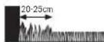
YbBahe: TpeBata octBaTa HeKoCeHa np6n. 20 cm okOla TbDpN oBeKTHnn BbTn.
3aKpenete orpaHHTENHO BbKe C npBpTO KOJIpe Do 3apnHa tAchua, OmbHete To nNoctabTne DpyrHte KOnHeTa ha pactOtnHe np6n.50 cm.(BxKTe fHyrpa8) 3aTBoPeTe KOHTyPA HNOBeTe ORpaHHTENHO BbKe KbM 6opathata cTpHa Ha zapHATA CTAnu Taka, ye Ta e no npBaAHHNc CTOBPA KONUToe.3aKpenete BTOPNKpaH a OrpaHHTENHO BbKe cbIO C konue.YBepTe ce, ye OTBopa, DBaTA Kpar HA BbXeTO,KAKTO H KONUTo Ca HA edha LNNHn. OTPkeTe ORpaHHTENHO BbKe,OTCPaHETe BHMaTeHNO H3oLaIaNTa H 3axBaHete ORpaHHTENHO BbKe KbM NbBata npCbeHNHTenHa KNema (UepHo). (BxKTe fHyrpa11)
IocabeTe npedna3HnKaKoxyHa 3apHaTa cTahnra. (Bxte fpya 12)
YbTBaHc:OtnbHnTeHNO OOrpaHnHTeHNO BbKe MoKe Da 6bJe NoctabeHo Cbc CbeHNHe. (BxKTe Dnpya 9)
OrpaHHTeHOTBbXeMoXeJa6bJeYbIJaBaHOHaMHoro do 450m.
YnbTbAe:KoratoBepTHkyInpateHnNNouchBaTe TpeBHaTa nIOu c rpe6no, cnaaBaIte paactoHne do orpaHHHTeHOTO Bbke.
HcTnPaTe 3axpaHbAunMyDnBnPoxnaHaCyxa
peJa.CbBpKTeTo Cbc3apdHataCTaHmN KOHTAKHa
3axpaHbAunMa MpeKa, KOITo E B3aTBoPeHO NOMEueHne B
crpa.(BnKteOfpyra13)
TbpBOHaayanHOHCTaHnpaHe
BkapaIte npkebcaBaHa h3axpaHbAunTOK B rpaHnckn EeKTPoHHCTpyMeHTNIOCTaBeTe eEeKTPoHHCTpyMeHTaB 3apHnHATA CTAnu. (BHXTe Dmpyn 15-17)
IorBaCe HauHnHrT EKpaH CbC CneHNHe CmBOHn:
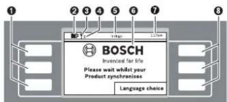
Cnmbon3haueHne
1 NeBHHMHorOyHKUHOHANHNKNABHUN
yka3aTeI 3a cBcToHHeTO Ha6aTePnTa
TpeBOKocayKaTa e Cbbp3Ha c GSM-MpeKaTa
H3aKaBaHe 3a CbP3BaHe c GSM-MpejkaT
S TpeBOKocKaTa e CbP3Ha CbCcbPbBa
H3aKaBaHe 3a CbBpBaHe cbc cbPbpa
HaHMeHOBaHHe Ha MeHIO/NoMHeHO
DnCnne CekpaHHn DnaNo3n
7 1ac
3 DeCHMHOFOHKOHOHAHNKNAHNI
*Indego ... Connect
BytoHnTe h3nJIHnBaT pa3nHnHn FyHKnN. TeKyuata
fYHKnna 3aBnCn O kTyAJHO TO MeHIO n Ce H3o6pa3raHa Ha ekpHa.
BytoHNTe DO CnMBOJNTe-CTpeKNK (KypcOp) ANH NIO3BOJRBAT HABHARINHTA HArOpe HN HADONY PNE3 ONIHTE HA MEHIO. BytoHNTe DO CnMBOJNTe-CTpeKNK (KypcOp) NIO3BOJRBAT PNDBHXBAHETO HADCHO HN HAIIBBO B OONHTE HA MEHOTO.

Блгарск | 353
IinrnnnntnpemnnaBk mcndeBaunr ekpanen dnanorob np03opeu, kOrato 6bne 36paHa n NotBbppeHa onnua.
Hhctanhpane
IbpoBaHauHaHO HaTHcHete 6yToHHe Do «Language choice» (N36op Ha e3NK). IoRaBA ce dHaNoTOrBnT npO3opeu. «N36op Ha e3NK» cbc cneHToC bcbpKaHne.
| № | Избор на[eзκ] | 1:27pm |
| √ | English | ▲ |
| Deutsch | ||
| Dansk | ||
| Svenska | ||
| Norsk | ▼ | |
| Suomi | ||
| 3аразметаBaHe |
H36epete e3NK IIO nO TnBpDte C 6yToHa 3anaMeTBAHe.
| Избор на Perион | 1:27pm | |
| ✓Еврona,южна Еврona,запада Еврona,северна Еврona,UK Еврona,нstoоча | ▲ | |
| ▼ | ||
| П配电етаhe | Запаметаhe | |
H36epete perehona, B KOITIO ue CE non3Ba Indego, H ro nOTBbPdTe C 6yToHa «3anaMeTBAHe».
Ta3n HNΦOPMaJrCe H3NOJ3Ba 3a OINTMnH3PnaHe h eNEKTPoHHN KOMnAC Ha TpeBOKocKaKaTpa-po60T.
| ПИН kod | 1:27рm |
| Моля, заиме ПИH | |
| Пюдьлжаваhe |
HaHCHETePpOdbNkBaHe,3aJaBbBeTeNEpcHOHnHn HnH KoI.
Tuk BbBedeTe BaHnI NIN KOJ.
YnbTbae:PiaeTe\PiH KoJa cH OT pa3KpBaHe npedpyrnnuca.
Ako 3ary6bte INH KOa cna, 3a de6loKpHae Tp86Ba da 3ahece Indego h 3apdHata ctaHua B OTOPH3paH cepBn3 3a eEkeTPOINCTpyMeHTHa BOo. MoN, CbpxTe ce c BaaWn CneuHn3HpA TbPROE u HnC bC cepBn3a Ha Boi (BHXte pa3dena «CepBn3 nTexHHueckn CbETn).
IIOH36paHHraPahKceN0AIBBaOTMeTKa
TpaHncknHrteeneKTPoHnCTpyMeHT3aOnOyBaKocHeTo,Korato HactbHrHtN36paHnHrTeHnHaC3aBpEmBeHnp0opeu1.
YnbTbAe: HactpoTe pa3nHrpaHc, Cb6pa3eHc pacteHTo HA tpeBata np3 pa3nHHTe ce3oHn - npOEt, Ito n eCen. Ha6IoJauBaTe pacteHTo HA tpeBata n npn Heo6xoHmOCT hactpoTe BBeHeHTe rpaHcN.
Kocehe
He donyckaite da ca ce Bo3r Bbpx rpaHnckn eneKtponHcTpymEnT.
PpeH da noBnHrte rpaHnckn H eNkTPOHnCTpyMeHT qe3dpbXkataMy 3a npHeacHe, HATNCKaTe 6yToHa 3a pbYeH cTOn.
BicouhnaHaKoceHe:BicouhnaHaKoceHeMoKeJaCe hactponMeKny20mm60mm(BHXTeΦHypa19). Bb3mOHHa10pa3nHnCHToHocTH(npHb.20mm, 24mm,29mm,33mm,38mm,42mm,47mm,51mm, 56mmH60mm).
YnbTbHe: PekeunrM OynHa Indego e npoeKtnpaH 3a p3aHe Ha Kbca TpeBa (3-5 mm). Okocehata TpeBa MoKe da octaHe HA TpeBHATA NIOU KATO eCTcTBHea TOP
YnbTaBe:Ppe3 PbBHe 3 ceDMnH NaCTPOe BHCouHnata H KaOce He MeKdy CTeneH 5 M MAX, 3a Da He 6bE OpRzHaHO orpaHnHTenHTo BbKe. Cne3 ceDMn BbKeTo e cKPto OT TpeBa.
HactpoTe rpaKc cecTo nobTaepaCe Kocene. Taka
pe3yTATnTe OTOKcHETO caDobpN, AkyMynAtopHATA
bATEPn H3bPka No-bIPO H3BraTe NaHaTe Ho
OTPA3A TeBa NO Koceha NIOu.
Korato KoceHETO 3anoyHano:
- rpaHncknpatpo6oTpa6oTHBpeKmA PbyeH,doKaTo nIooTa 6bde OKoceh HINb6de HATNCHAT 6yTOHa cTOn. KocHeTe ce npkecba 3a 3apeXda He akyMnatopHaTa batePn.
IpaHnckHrTeEeKTPoHcTpyMeH paOToB pOporpaMepeXIMA PPAHbPaMKte Ha 3aDaeHe BpEmEBnpo3opeu.3aJa npeKcbete Koceheto npEn kpaHa BpEmEBn np3opeuHa,HaTHcHete6yToHa 3aPbueH cToN.Ako TpeBnata NIOo5 bDe oKoceha npEn n3TuHa He BpEmEBn np3opeu. IpaHnckHrHTeEeKTPoHcTpyMeHce BpUa np3apdHaCTaHua
EfeKTHBNO KocHe c Logicut
Iokonko efeekTHBHO Kocn Indego (BHXTe pHypTa 20)
3a da pa60TH eΦeKTHBNO, Indego n3yUba pIIOuT, KOrTo 6pa60Ta. Ppoedypara no n3yUbaHeto ce cbctOn No BpeMe Ha IpbNTe Dba pa60THn cKbJa.
No-donye o6rcheHcK Ak Indego n3yUba foPmTa Ha TpeBnata nnou.
Функунова Тaka
OD
3a da Kocn efekTHBHO. Indego KaptorpaHpa BbHnHaTahn HnHa TpeBHATA NIOUOHN ONo3NHTA HnHAMPAaNTe Ce BbTpE o6ekTN (DbpBeta, ubeTHNEXX, BOHN IIOOIN HApI. KOTNO BPeMe HA INCTALIPAHeto Ca 6bnn ORpaDEH COrpAHmHTENHO BBeK. Taka Indego MoeJa nH3uCNKbDeHMA OoSe TpeBa 3a KcOeHe, KbTe TpeBata Beye e6bnna OKocehn IIbTdoN OTO 3apndata CTAnu. BCJeCTBHe Ha TOBa Indego E B cBctOHHe Da nH3bHn 3daayata 3hauNTENHO noeFekTHBHO.
KaptorpaΦnpahe Ha pa6oTHata nnoou (BHXTe ΦHrypa 20)
CnE KaTo HAcTpoKInTe ca N3BbPWeHn, Indego nbpO KApToIpaΦpA BbHbHATAΦopMa Ha TpeBHATA IIOU. ToBa ce N3BbPbWAupe3 06XoXdHe Ha OrpAHuHTeHnTO BxKe No pba Ha TpeBHATA IIOU. NpBeme Ha 06XoXdHaero Indego N3MepBa pa3cToHHa, rHeHpPa KapTa n 3aIIncBA B naMeTA.
YnbTbAe:Indego He cneBba orpaHnHTenHOTo BbXe, orpaKaDIO BbTpewHInTe 06kTN.
M3yuaBaHe Ha No3nHa HrpaHncknte 06eKn, orpaedHc oPraHnHTeHnHOTo BbXe (BHXTe pHypTa 20)
Cnqkato Indego e Kaptorpaipan niou ta 3a KocHe, moKe da 3anoue camoto kocHe. Cnq noDaBaHe ha Komahata «KocHe» Indego hanycka 3apdHa tcaHnna H 3aoVb da Kocn TpeBaHa y cnpoeHHn IBuHn. YcnpoeHNte NBuHn ca orpahnHn noDbJKNHa do npH6n. 10 m, 3a da moKe cnqdata Da ce cna3BA no-touHo. YacTt oT obuaT a nnoi ce OKoCBA Ha cynpoeHHn IBuHn, OCBEN AKO He bJe cpeHnat OrpaeH corpahnHntHo BbJke oBeKT.
Ako6bdeOTKpHTaKbB06ekt,IndegoCneJBA
OrpaHnHTenHTo Bxke OKOIO 06ekta,3a da ONpeJEN
fOpMaTMy.3a ToHOTOn ONpeJEnHe Ha NOnuJrTa H
06kta Indego OTNBA DO OrpaHnHTenHTo Bxke NO
IepmpePrrHa Ha rpaHnHata H3aNCBa KoopDnHaTte B
KaptTaHa rpaHnHata.CnE Toba Indego npOdbNkBa
KocEHeto.AKO no BpeMe HA KocEHeto Indego nonadHe Ha
dpytn 06kTHn,pouecBt Ce NoBtapA.CnE pNKnIOvBaHe Ha
paBoTata Indego ce Bpuia oBpatHO B sapRnHa cTAncu.
YbTaBe: PpOecBt CnOBTpA npH BTOPO TKeCHe. TaKa cOcNpyBaHaNeJHO TOKPNBaHE Ha OeKTHTe, TOHOTOnOpEJIeHa H MeTcONIOXeEHnTo H BrpaHnHATA H 3aIINCbAHETo H bKaprTaH aRpaHnHata.
Блгарск | 357
Ako6bdatOTKPNTHpyrno6eKTHBpndnHata,Indego npoDbjKabKaOcEHeTO HOpMaIHO.
Ako cIeHnCTaIIHpAHe Tpr6Ba da 6bJe N3KIOueHa HOBa nnoou BpAMKHe Ta rpaHInata (Hanp. 3a IbeTa Iexa), M0ke Da 6bJe DoabBeHO DOnBfHNTeIHNO OrpaHInTeIH NO Bxke C Kaaben HcEINHIn. (BHXte Chpyra 10)
PeknKoceHe(BxTeΦHypa 20)
CnE KATO Indego e H3yH MecToIOnIOKeHHeTO Ha BCNUK oBekTH B rpaHATA, ToI KOCH TpeBHATA IIIOUeΦeKTNBHO NO ycnpedHNHHN.
P3aHe C DBOHaCKopoCT
Ako no Bpeme Ha KocHe Indego nonaH He HBCOKa Hn HbCTa TpeBa, yBnHab ABOtMATHUHO CKOPOCTHa HbPteHe HApeKeIaTa CHCTeMa HAmalnBA CKOPOCTHa HnpemctBAHE, DOKATO CBOBTBHTOHO MRCTO e OKOECHO.
Kocene do pb6
BTo3n pexkM Indego Kocn no npOdbNkeHne Ha orpaHnHTeHOTo BbKc. YecTOTATA epeynHypeMa. IOnnpa3bHpAte TOBa Ce N3BpUba HA BCaQ YeTBbPto KOCEHe.
PnHnOKpBaHe Ha TpaEKTopHaTa
IndegoKoCnTpeBaTaHaYcIOpEHNINHHNcBJIHHNHa 10 m.Pa3oTHHnetoMekJyNHnHTe HAcTPOEHNO no nOpa3bHpaHa 20 cm,HO npn BmCOKa TpeBa CE HAanra BAOTOMaTHNo.KoTAo CbOTBeHTo MRCTo EOKOceHo,pabOtata PpOdbJXaba C HAcTpoEHTO NO npOpa3bHpaHe paoCTHnHe.Ta3n HAcTPOHKMOKe Da Ce pOMeHr OT notpe6HTen ype3 MeHTo.
Cen3opn
TpaHnckmTpo6oT npHTeKaBa cneHnTe ceH3Op:
Cen3OpBt 3a nobHrane Ce kTbnpa H3KnIOUBa DnIraTeN HOKoBeTe, KOrTa TpaDnHCKnT eNEKTPOnHCTpyMeHT 6De BnHrHat.
Cen3opb3a npeo6pbuahe paan03haba daHn IpaHnckHt enekTPOHNCTpyMeHT e 06bpHAT cDOnHaTa CtpaHa HaroPe NkKnIOvBA DInrataeN HOXOBete.
Cen3OpBt 3a 6nokHpae pa3n03HaBa Dnnp C npENTCTBME NO TpaEKTOPRHTA Ha rpaDnHcKna eNEKToPNCHTpMEnI NpeIN3BKNBa CMHa Ha IIOcOKaTa HA DBKeHMe.
Cen3OpBt 3a HKnOH Ce aKTHINbPa, KOraTo rpaHnHcknT eJekTPOHHCTpyMeHT DocTHrHe HKnOH 45°.
Ako 6bde 3aedcTBaH HKOI OT CEH3OpHTe, Hanp. ceH3OpBT 3a NobHrAne, Ha dncnEe Ce noRBA cbo6uHHeNoTo: DPradHncknTpyed e NOBnHAT. MoN, BBeDete NIN, 3a da npOdbnKInTe. JDCnPte CE hKIOUBA, aKo B npOdbnKHe He 10 MInyTH He 6bde BBeBedeHO HmIo. 3a da BKNIOUHe dncnEer OTHBO, HATChETe POnH3BOJeB6yTOh Korato rpaDHnCKnT eNEkTPOMHCTpyMeH e B NOKoi, HATChETe POnH3BOJeH KAnH, 3a Da h3BNKe t EkpHa 3a BBBeJxJaHe HIN KOA.
3apekdahe Ha akymylaTophata 6aepn
Akymnyatopnata 6atepna e cbrpaedeha temepatypha 3aunta, kanto no3B0nra 3apekdaheTo caMo B TEMepatypnH INTEPbaN Mekdy 5^ n 45^
Inthebo-ohhata akymnatopha batepna ce doctabra
aactHHo zapeHema.3a daocHTHeTe bHnHn KaanuTET,
npenMbPbTO BkUOVAhe Ha rpaHnCKHn
eKETPOHnCTpyMeT IOCTABe T da ce 3apeHN HbIHO B
3aepnHa CTAHN.
IHTeBO-NOHHaTakAkyMnATOPHaBatePmR MoKeJa6bDe 3apeXdHaNoBCaKoBpeMe,6e3ToBaDaCbKpaUaBa 1bTOrpAHHocTtA.NIpeKbCBAHeHa3apeXdaHeTO CbUHO He Bpei.
Korato akymnatopnata batepe nce H3tou, rpaHNCKnT eNekTPOHNCTpyMeNT CE h3KnOyBa OT npednaeH npeKbCBAU HOKOBeTe CNPaT da ce DBHXaT.
358|Блгарский
Ta6nua 3a nporpamnpahe
TabinHHTeNo-donyo6bChHBaPpa3nHHHeEJEMeHTHaMeHIOta.
| Параметробъединения | ||
| Настойки Косеve | Косеve до рбба | Нikога |
| Всяк четвьрtnпьт | ||
| Всяк втори пьт | ||
| Винаги | ||
| Прилескг. на Траек. | ||
| Ид сигал | Изговае на Градиа | |
| Заточа на Дугчык Балд Балд Балд Балд Балд Балд Балд Балд Балд Балд Балд Балд Балд Балд Балд Балд Балд Балд Балд Балд Балд Балд Балд Балд Балд Балл Балл Балл Балл Балл Балл Балл Балл Балл Балл Балл Балл Балл Балл Балл Балл Балл Балл Балл Балл Балл Балл Балл Балл Балл Балlla Балл Балл Балл Балл Балл Балл Балл Балл Балл Балл Балл Балл Балл Балл Балл Балл Балл Балл Балл Балл Балл Балл Балл Балл Балlor Балlor Балlor Балlor Балlor Балlor Балlor Балlor Балlor Балlor Балlor Балlor Балlor Балlor Балlor Балlor Балlor Балlor Балlor Балlor Балlor Балlor Балlor Балlor Балlor Балл Балlor Балlor Балlor Балlor Балlor Балlor Балlor Балlor Балlor Балlor Балlor Балlor Балlor Балlor Балlor Балlor Балlor Балlor Балlor Балlor Балlor Балlor Балlor Балл Балл Балlor Балlor Балlor Балlor Балlor Балlor Балlor Балlor Балlor Балlor Балlor Балlor Балlor Балlor Балlor Балlor Балlor Балlor Балlor Балlor Балlor Балlor Балл Балlor Балл Балlor Балlor Балlor Балlor Балlor Балlor Балlor Балlor Балlor Балlor Балlor Балlor Балlor Балlor Балlor Балlor Балlor Балlor Балlor Балlor Балlor Балlor Балл Балл Балл Балlor Балlor Балlor Балlor Балlor Балlor Балlor Балlor Балlor Балlor Балlor Балlor Балlor Балlor Балlor Балlor Балlor Балlor Балlor Балlor Балlor Балл Балlor Балlor Балл Балlor Балlor Балlor Балlor Балlor Балlor Балlor Балlor Балlor Балlor Балlor Балlor Балlor Балlor Балlor Балlor Балlor Балlor Балlor Балlor Балlor Балл Балlor Балл Балл Балlor Балlor Балlor Балlor Балlor Балlor Балlor Балlor Балlor Балlor Балlor Балlor Балlor Балlor Балlor Балlor Балlor Балlor Балlor Балlor Балlor Балл Балл Балlor Балл Балlor Балlor Балlor Балlor Балlor Балlor Балlor Балlor Балlor Балlor Балlor Балlor Балlor Балlor Балlor Балlor Балlor Балlor Балlor Балlor Балlor Балл Балл Балл Балл Балlor Балlor Балlor Балlor Балlor Балlor Балlor Балlor Балlor Балlor Балlor Балlor Балlor Балlor Балlor Балlor Балlor Балlor Балlor Балlor Балл Балlor Балlor Балlor Балл Балlor Балlor Балlor Балlor Балlor Балlor Балlor Балlor Балlor Балlor Балlor Балlor Балlor Балlor Балlor Балlor Балlor Балlor Балlor Балlor Балл Балlor Балlor Балл Балл Балlor Балlor Балlor Балlor Балlor Балlor Балlor Балlor Балlor Балlor Балlor Балlor Балlor Балlor Балlor Балlor Балlor Балlor Балlor Балlor Балл Балlor Балл Балlor Балл Балlor Балlor Балlor Балlor Балlor Балlor Балlor Балlor Балlor Балlor Балlor Балlor Балlor Балlor Балlor Балlor Балlor Балlor Балlor Балlor Бал劳 Балlor Балlor Балlor Балlor Балlor Балlor Балlor Балlor Балlor Балlor Балlor Балlor Балlor Балlor Балlor Балlor Балlor Балlor Балlor Балlor Балlor Балlor Балlor Балlor Бал劳 Балlor Балlor Балlor Бал劳 Балlor Балlor Балlor Балlor Балlor Балlor Балlor Балlor Балlor Балlor Балlor Балlor Балlor Балlor Балlor Балlor Балlor Балlor Балlor Балlor Бал劳 Балlor Балlor Балlor Балtor Балlor Балlor Балlor Балlor Балlor Балlor Балlor Балlor Балlor Балlor Балlor Балlor Балlor Балlor Балlor Балlor Балlor Балlor Балlor Балlor Балlor Балlor Балlor Балlor Бал耗 Бал耗 Бал耗 Бал耗 Бал耗 Бал耗 Бал耗 Бал耗 Бал耗 Бал耗 Бал耗 Бал耗 Бал耗 Бал耗 Бал耗 Бал耗 Бал耗 Бал耗 Бал耗 Бал耗 Бал耗 Бал耗 Бал耗 Бал耗 Бал耗 Балlor Балlor Балlor Балlor Балlor Балlor Балlor Балlor Балlor Балlor Балlor Балlor Балlor Балlor Балlor Балlor Балlor Балlor Балlor Балlor Балlor Балlor Балlor Балlor Бал死 Балlor Балlor Балlor Балlor Балlor Балlor Балlor Балlor Балlor Балlor Балlor Балlor Балlor Балlor Балlor Балlor Балlor Балlor Балlor Балlor Балlor Балlor Балlor Балlor Бал网 Бал网 Бал网 Бал网 Бал网 Бал网 Бал网 Бал网 Бал网 Бал网 Бал网 Бал网 Бал网 Бал网 Бал网 Бал网 Бал网 Бал网 Бал网 Бал网 Бал网 Бал网 Бал网 Бал网 Бал网 Бал劳 Бал劳 Бал劳 Бал劳 Бал劳 Бал劳 Бал劳 Бал劳 Бал劳 Бал劳 Бал劳 Бал劳 Бал劳 Бал劳 Бал劳 Бал劳 Бал劳 Бал劳 Бал劳 Бал劳 Бал劳 Бал劳 Бал劳 Бал劳 Бал劳 Бал网 Бал网 Бал网 Бал网 Бал网 Бал网 Бал网 Бал网 Бал网 Бал网 Бал网 Бал网 Бал网 Бал网 Бал网 Бал网 Бал网 Бал网 Бал网 Бал网 Бал网 Бал网 Бал网 Бал网 Бал冈 Бал网 Бал网 Бал网 Бал网 Бал网 Бал网 Бал网 Бал网 Бал网 Бал网 Бал网 Бал网 Бал网 Бал网 Бал网 Бал网 Бал网 Бал网 Бал网 Бал网 Бал网 Бал网 Бал网 Бал网 Бал网点 Бал网 Бал网 Бал网 Бал网 Бал网 Бал网 Бал网 Бал网 Бал网 Бал网 Бал网 Бал网 Бал网 Бал网 Бал网 Бал网 Бал网 Бал网 Бал网 Бал网 Бал网 Бал网 Бал网 Бал网 Бал阀 Бал网 Бал网 Бал网 Бал网 Бал网 Бал网 Бал网 Бал网 Бал网 Бал网 Бал网 Бал网 Бал网 Бал网 Бал网 Бал网 Бал网 Бал网 Бал网 Бал网 Бал网 Бал网 Бал网 Бал网 Бал网上 Бал网 Бал网 Бал网 Бал网 Бал网 Бал网 Бал网 Бал网 Бал网 Бал网 Бал网 Бал网 Бал网 Бал网 Бал网 Бал网 Бал网 Бал网 Бал网 Бал网 Бал网 Бал网 Бал网 Бал网 Бал面 Спсг Спсг Спсг Спсг Спсг Спсг Спсг Спсг Спсг Спсг Спсг Спсг Спсг Спсг Спсг Спсг Спсг Спсг Спсг Спсг Спсg Спсg Спсg Спсg Спсg Спсg Спсg Спсg Спсg Спсg Спсg Спсg Спсg Спсg Спсg Спсg Спсg Спсg Спсg Спсg Спсг Спсg Спсg Спсg Спсg Спсg Спсg Спсg Спсg Спсg Спсg Спсg Спсg Спсg Спсg Спсg Спсg Спсg Спсg Спсг Спсг Спсg Спсg Спсg Спсg Спсg Спсg Спсg Спсg Спсg Спсg Спсg Спсg Спсg Спсg Спсg Спсg Спсg Спсг Спсg Спсг Спсg Спсg Спсg Спсg Спсg Спсg Спсg Спсg Спсg Спсg Спсg Спсg Спсg Спсg Спсg Спсg Спсg Спсг Спсг Спсг Спсg Спсg Спсg Спсg Спсg Спсg Спсg Спсg Спсg Спсg Спсg Спсg Спсg Спсg Спсg Спсg Спсг Спсg Спсg Спсг Спсg Спсg Спсg Спсg Спсg Спсg Спсg Спсg Спсg Спсg Спсg Спсg Спсg Спсg Спсg Спсg Спсг Спсg Спсг Спсг Спсg Спсg Спсg Спсg Спсg Спсg Спсg Спсg Спсg Спсg Спсg Спсg Спсg Спсg Спсg Спсg Спсг Спсг Спсg Спсг Спсg Спсg Спсg Спсg Спсg Спсg Спсg Спсg Спсg Спсg Спсg Cngs Cngs Cngs Cngs Cngs Cngs Cngs Cngs Cngs Cngs Cngs Cngs Cngs Cngs Cngs Cngs Cngs Cngs Cngs Cngs Cngs Cngs Cngs Cngs Cngs Cngc Cngs Cngs Cngs Cngs Cngs Cngs Cngs Cngs Cngs Cngs Cngs Cngs Cngs Cngs Cngs Cngs Cngs Cngs Cngs Cngs Cngs Cngs Cngs Cngs CngS Cngs Cngs Cngs Cngs Cngs Cngs Cngs Cngs Cngs Cngs Cngs Cngs Cngs Cngs Cngs Cngs Cngs Cngs Cngs Cngs Cngs Cngs Cngs Cngs Cngg Cngs Cngs Cngs Cngs Cngs Cngs Cngs Cngs Cngs Cngs Cngs Cngs Cngs Cngs Cngs Cngs Cngs Cngs Cngs Cngs Cngs Cngs Cngs Cngs Cpgs Cpgs Cpgs Cpgs Cpgs Cpgs Cpgs Cpgs Cpgs Cpgs Cpgs Cpgs Cpgs Cpgs Cpgs Cpgs Cpgs Cpgs Cpgs Cpgs Cpgs Cpgs Cpgs Cpgs Cpgs Cngs Cngs Cngs Cngs Cngs Cngs Cngs Cngs Cngs Cngs Cngs Cngs Cngs Cngs Cngs Cngs Cngs Cngs Cngs Cngs Cngs Cngs Cngs Cngs Cpgg Cpgs Cpgs Cpgs Cpgs Cpgs Cpgs Cpgs Cpgs Cpgs Cpgs Cpgs Cpgs Cpgs Cpgs Cpgs Cpgs Cpgs Cpgs Cpgs Cpgs Cpgs Cpgs Cpgs Cpgs CpgS CpgS CpgS CpgS CpgS CpgS CpgS CpgS CpgS CpgS CpgS CpgS CpgS CpgS CpgS CpgS CpgS CpgS CpgS CpgS CpgS CpgS CpgS CpgS CpgS Cpgs CpgS CpgS CpgS CpgS CpgS CpgS CpgS CpgS CpgS CpgS CpgS CpgS CpgS CpgS CpgS CpgS CpgS CpgS CpgS CpgS CpgS CpgS CpgS Cpgs Cpgs CpgS CpgS CpgS CpgS CpgS CpgS CpgS CpgS CpgS CpgS CpgS CpgS CpgS CpgS CpgS CpgS CpgS CpgS CpgS CpgS CpgS CpgS Cpgs CpgS Cpgs CpgS CpgS CpgS CpgS CpgS CpgS CpgS CpgS CpgS CpgS CpgS CpgS CpgS CpgS CpgS CpgS CpgS CpgS CpgS CpgS CpgS CpgS Cpgs Cpgs Cpgs CpgS CpgS CpgS CpgS CpgS CpgS CpgS CpgS CpgS CpgS CpgS CpgS CpgS CpgS CpgS CpgS CpgS CpgS CpgS CpgS CpgS Cpgs CpgS CpgS Cpgs CpgS CpgS CpgS CpgS CpgS CpgS CpgS CpgS CpgS CpgS CpgS CpgS CpgS CpgS CpgS CpgS CpgS CpgS CpgS CpgS CpgS Cpgs CpgS Cpgs Cpgs CpgS CpgS CpgS CpgS CpgS CpgS CpgS CpgS CpgS CpgS CpgS CpgS CpgS CpgS CpgS CpgS CpgS CpgS CpgS CpgS CpgS Cpgs | ||

BbIrapckn | 359
www.bosch-garden.com
BnHaH KOrAo ce 06bpuate C Bbnpoc KbM
PnpctaBntenite Ha Booi HnpeMeHHo NocOyBaTe 10-
NtEeKpEnH KATAOKeH HOMep Ha rpaHnckn
eneKpOHnCTpyMeHT.
Ako ce HANOxN, BnHaHn H3npaIaIte 3aeDHO TpeBOKocKaTApo60 n3apdHata cAnuB C cepBn3eH uehtb np Ho.
B DonbHHeHne e Heo6xOma BepcnHa Ha coptyepa Ha BaIINr pndHcNEnEeKtpOnHCTpyMeHT (BHXTe MeHIO> HAcTpOKn > CnCTemHn HAcTpOKn > HnΦo).
PoBepr BoW EOOI-BbIraPn
Boi CepBaNzIeHtpb
TapaHIOHHN H3BbHrapaHIOHHpeMOHTN
6yn. YepHN Bpbx 51-6
FPI Bn3HeC 1407
1907CoΦnA
Ten.: (02) 9601061
Ten.: (02) 9601079
ΦaKc: (02) 9625302
www.bosch.bg
TpaHcnopTpnpaHe
BKnOyehHe BOKMnEeKToBkata NmTHeo-HOHN AHymnytapOnH bateepn Ca B 06xBata Ha NsCKBaHnraHa HOPMaTHBHeDOKyMeHTN, Kacaeeu npOdyKTn C NOBHnEA onaHcOT. AkymnatOpHTHe bateepn Morat Da 6bDat TpAChnOPTPAnH OT NTpe6HTenHa Npy6hNHN MeCTa 63 DOnblHHTENH pa3peWHTENH.
Pn TpaHCnpTpaHEOTpeTHCpTaHH (Happ. npb Bb3dywee TpAHCNOPTNINON3BaHE HA KpynePCKM Ycnyr) NMa CneuHaHN H3NCCKBAHNA KbM ONaKOBaHETo H 06o3HaVaBaHeTo MM.3a ce Ta CE KOHCyTNpaTe CekneptB CbOtBeHTa Obnact.
Бракуван.
He 3xBprrte rpaHnck enektpnoHcTpymEn, 3apdyn yctpoiCTBa n akymnatopn Hn o6nkOBen 6atepn np 6HTOBTE Otnabu!
Cama 3a CtpaHH oT EC:
CbrrnacHo EbponeNcKa DnpeKTHBa 2012/19/EC OTHoCHO H3r3na OTynoTp6a
eneKtpnuecka N eEeKToPOnHa anapatya n
cbrrnacHo EbponeNcKa DnpeKTHBa 2006/66/EO AkyMynatopHn INn
06nKnHOBeHn 6atePHn, KOtO He MoRat Da Ce
H3no3BaT NOBuey,TPa6Ba Da ce cb6npaTOnENHOda6bDat NoDnaHnHaNoXoJaA ppepa60ka 3a onon3oTBopBAHe HaCbPjxauHTe CeBTX CypOBHH.
Donycka ce BRpadeHnTe akyMnaTOpHN batepHn da ce H3BaXaAT caMo np6paKyBaHe. Pnp OTBapRHe Ha cepynKHe HA Kopnyca rpaDnHcKnr TeneKTPOINHCTpyMeHT MoKe da 6bne NoBpehen.
Donycka ce 6pakybaHeTo Ha BrpadeHn AkymyNaTOpHN 6aTePHN Da CE N3BbPbWA CaMo B OTOpHmpan CepBN3 3a eNEKTPoHHCTpyMEnTH Ha Boi.
AkymyaToHHHn06hKHOBeHH 6aTePHH:
MOna, cna3BaIte yka3AHnTa Bpa3dena. Tr optipane>.
Ppabata 3a 3nMeHeHna3aNa3eHN.
Srpski
Puno se Zahvaljujemo, sto ste se odlucili za Indego Roboter za koosenje.
Procitaje molimo sledeca uputstva za sigurnost, preNgu sto instalirate Indego.
Sigurnosna uputstva
Paznja! Procitajte pažljivo sledeca uputstva. Upoznajte se sa elementima za rad i propisnom upotrebom bastenskog uredjaja.
Molimo sačuvajte sigurno uputstvo za rad za kasniju upotrebu.
Objasnjenja symbola na bastenskom uredjaju

Opste uputstvo o opasnosti. Uverite se da kroz bastenski uredjaj nisu blokirani neki izlazi ili zatvoreni.

Opomena: Citajte radno uputstvo preNgu sto pustite u rad bastenski uredjaj.

Henk Becker
Executive Vice President
Engineering
Helmut Heinzelmann
Head of Product Certification
PT/ETM9

Robert Bosch GmbH, Power Tools Division 70764 Leinfelden-Echterdingen, GERMANY Leinfelden, 27.10.2015


368 | Srpski
Objašnjenje slika za instalaciju (pogledajte stranice 3-14)
| Cijl rukovanja Slika Strana | |
| Obim isporuke/raspakivanje bašenskog uredjaja | 14 |
| Pozicioniranje uredjaja za punjenje | 2-4 4-6 |
| Graničnužicu sprovesti kroz podnuclochu | 56 |
| Prikljuciti prvi kraj grančnežice | 66 |
| Pričvstiti uredjaj za punjenje na podu | 76 |
| Postavite grančnužicu | 87 |
| Produžavanje grančkežice | 98 |
| Iskljuciti dodatno područje sa graničnom Žicom 108 | |
| Prikljuciti drugi kraj grančnežice | 119 |
| Stavite zašitnu haubu na uredjaj za punjenje | 129 |
| Prikljuciti uredjaj za snabdevanje strujom 1310 | |
| Uredjaj za punjenje signalizira mrežni napon UKLJUCENO | 1410 |
| Umetutni prekidač strujnog kruga | 1510 |
| Staviti bašenski uredjaj za punjenje u uredjaj za punjenje | 1611 |
| „Dobro došil“-Ekran, pogledaje tekst u uputstvu za rad 1711 | |
| Podić i nositi bašenski uredjaj | 1812 |
| Podesiti visinu sećenja | 1912 |
| Uspešno kosi sa Logicut | 2013 |
| Čićsjenje | A14 |
| Održavanje | B14 |
Priprema utrine
Uklonite kamenje, slobodne drivene komade, zice, kablove za snabdevanje strujom koji su pod naponom i druge strane predmete sa povrsine koju treba kositi.
Uverite se, da je povrsina za kosenje ravna i da nePokazuje za bastenski uredjaj nikakve jasne smetnej kao udobljena, kanale i kose povrsine preko 20^
Kosite glavnu povrsinu utrine sa konvencionalnom kosacicom na visini od maksimalno 40mm a podruce preko granice ziice na visini od maksimalno 20mm
Instalacija
Video o instalaciji Indego je raspaloživ pod www.bosch-indego.com il upotrebite sledeci QR-code.

Birajte pozicij zu uredjaz punjenne, horizontaln nivelisan i ne na direktnom sumcvom zracenju.
Uputstvo: Uredjaj za punjenje mora da se poziconira na nekoj od spoljinih ivica povrsine livade na graničnjžić. On ne要考虑 da stoji na strani neke supe ili kucice za uredjav, koji stojke aco strovo unutar povrsine livade.
www.bosch-garden.com
Molimo navedie kod svih pitanja i narucivanje rezervnih delova neizostavno broj predmeta sa 10 mesta prema tipskoj tablici bastenskog uredjaja.
Pristojni organ 2000/14/ES:
SRL, Sudbury, England, Nr. 1088
Tehnicdokumentaciya (2006/42/ES, 2000/14/ES) pri:
Bosch Lawn and Garden Ltd., PT-HG/ENS-PA2, Stowmarket, Suffolk IP14 1EY, England
Henk Becker
Executive Vice President Engineering
Helmut Heinzelmann
Head of Product Certification PT/ETM9


Robert Bosch GmbH, Power Tools Division
70764 Leinfelden-Echterdingen, GERMANY
www.bosch-garden.com
Bosch Lawn and Garden Ltd., PT-HG/ENS-PA2, Stowmarket, Suffolk IP14 1EY, England
Henk Becker
Executive Vice President Engineering
Helmut Heinzelmann
Head of Product Certification PT/ETM9

i. v. k = m _____
Robert Bosch GmbH, Power Tools Division 70764 Leinfelden Echterdingen, GERMANY Leinfelden,27.10.2015

Hrvatski 399
Objašnjenje slika za instaliranje (vidjeti stranice 3-14)
Radnja Slika Stranica
| Raspakirati sadržaj isporuke/vrtni uredaj | 14 |
| Pozicionirati stanicu za punjenje | 2-4 4-6 |
| Provuci graničnu Žicu kroz podnuploču | 56 |
| Prikljuciti prvi kraj granične Žice | 66 |
| Stanicu za punjenje pričvrstiti na tlo | 76 |
| Položiti granićnu Žicu | 87 |
| Produženje granične Žice | 98 |
| Dodatno područje trasirano s graničnom Žicom 10 8 | |
| Prikljuciti drugi kraj granične Žice | 119 |
| Postaviti zašitniPoklopac na stanicu za punjenje | 129 |
| Prikljuciti urežaj za opskrbu elektricknom energijom 13 10 | |
| Stanica za punjenje signalizira uključen mrežni napon | 1410 |
| Ugraditi prekidač strujnog kruga | 1510 |
| Vrtni uredaj za punjenje staviti u stanicu za punjenje | 1611 |
| Zaslon „Dobro došli“, vidi tekst u uputama za rukovanje 17 11 | |
| Podić i nositi vrtni urežaj | 1812 |
| Namejšanje visine rezanja | 1912 |
| Učinkovita košnja s pomoću Logicuta | 2013 |
| Čišćanje | A14 |
| Održavanje | B14 |
Priprema travnjaka
Povrsinu travnjaka koja ce se kositi ocistite od kamencica, komadica drva, ziice i ostalih stranih predmeta, a uklonite i priključni kabel koji se nalazi pod naponom.
www.bosch-garden.com
Kod svih upita i narucivanja rezervnih dijelova molimo neizostavno navedite 10-znamenkasti kataloski brojsa tipske ploice vrtnog ureda.
Ukoliko je potrebno, robotsko kosilicu i stanica zu punjenje uvijek zajedno posaljite u Bosch ovlasteni servisi ncentar.
Dodatno je potrebna verzija softvera vaseg vrtnog uredaja (vidi „Izbornik > Postavke > OpciJE sustava > Informacije").
Hrvatski
Robert Bosch d.o.o
Kneza Branimira 22
10040 Zagreb
Tel.: (01) 2958051
Fax: (01) 2958050
Transport
Li-ionske aku-baterije ugradene u elektrichnom alatu podljeezu zakuno o transportu opasnih tvari. Aku-baterije korisnik moze bez ikakvih preduvjeta transportirati cestovnim transportom. Ako transport obavlja treca strana (npr. transport zrakoplovom ili spedicijom), treba se pridrzavati posebnih zahtjeva obizroim na ambalauzi oznacavanje. Kod pripreme ovakvih posiljki za transport prethodno se treba savjetovati sa strucnjakom za transport opasnih tvari.
Zbrinjavanje
Vrtne uredaje, punjači aku-bateriju/baterijne bacajte u kučni opstad!
Samo za zemlje EU:

Bosch Lawn and Garden Ltd., PT-HG/ENS-PA2,
Stowmarket, Suffolk IP14 1EY, England
Henk Becker
Executive Vice President
Engineering
Helmut Heinzelmann
Head of Product Certification
PT/ETM9

a_i Q j T
Robert Bosch GmbH, Power Tools Division
70764 Leinfelden-Echterdingen, GERMANY
Alatörlistal on jargmised sensorid:
www.bosch-garden.com
Bosch Lawn and Garden Ltd., PT-HG/ENS-PA2,
Stowmarket, Suffolk IP14 1EY, England


430|Latviešu
Henk Becker
Executive Vice President
Engineering
Helmut Heinzelmann
Head of Product Certification
PT/ETM9

Robert Bosch GmbH, Power Tools Division 70764 Leinfelden-Echterdingen, GERMANY Leinfelden,27.10.2015
Paskaidrojumi pie atteliem par uzstadisanu (skatit lappuses 3-14)
www.bosch-garden.com
Pieprasot konsultacijs an pusutot rezerves dalas, ludzam noteikti pazinot desmitzimju pusutijuma numuru, kas noradits uz darza instrumenta markejura plaksnites.
Ja nepiecijsams, nosuit robotizeto zaliena plaveju kopa ar bazes staciju uz Bosch servisa centru.
Bez tam nepiecesams noradit darza instrumenta programmaturas versiju (skatit isceju, Izveline lestadijumi > Sistemas iestadijumi Informacija).
Latvijas Republika
Robert Bosch SIA
Bosch elektrinstrumentu servisa centrs
Bosch Lawn and Garden Ltd., PT-HG/ENS-PA2,
Stowmarket, Suffolk IP14 1EY, England
Henk Becker
Executive Vice President
Engineering
Helmut Heinzelmann
Head of Product Certification
PT/ETM9

a_i a j a a b b
Robert Bosch GmbH, Power Tools Division
70764 Leinfelden-Echterdingen, GERMANY
www.bosch-garden.com