Blue Chilled and Sparkling system - Sanitary GROHE - Free user manual and instructions
Find the device manual for free Blue Chilled and Sparkling system GROHE in PDF.
User questions about Blue Chilled and Sparkling system GROHE
0 question about this device. Answer the ones you know or ask your own.
Ask a new question about this device
Download the instructions for your Sanitary in PDF format for free! Find your manual Blue Chilled and Sparkling system - GROHE and take your electronic device back in hand. On this page are published all the documents necessary for the use of your device. Blue Chilled and Sparkling system by GROHE.
USER MANUAL Blue Chilled and Sparkling system GROHE
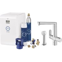
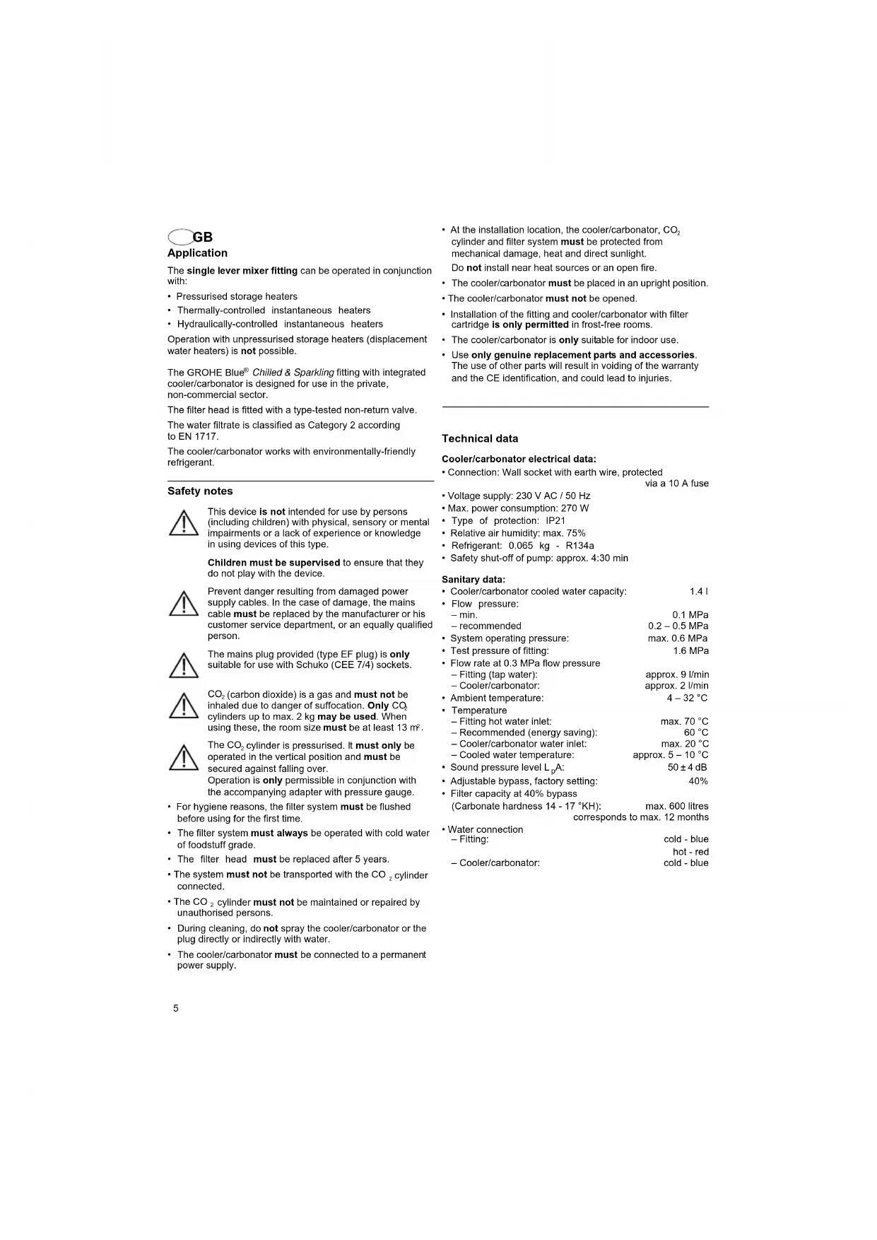
GROHE Blue® Chilled & Sparkling
GROHE Blue® Chilled & Sparkling
D 11 17 N 33 GR 49 TR 65 BG 81 RO 97
GB 5 NL 21 FIN 37 CZ 53 SK 69 EST 85 CN 101
F 9 S 25 PL 41 H .57 SLO .73 LV .89 UA .105
E 13 DK 29 UAE 45 P 61 HR 77 LT 93 RUS 109
Design + Engineering GROHE Germany
99.690.031/AM227098/02:13

ENJOY WATER
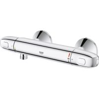
The single lever mixer fitting can be operated in conjunction with:
- Pressurised storage heaters
Thermally-controlled instantaneous heaters - Hydraulically-controlled instantaneous heaters
Operation with unpressurised storage heaters (displacement water heaters) is not possible.
The GROHE Blue Chilled & Sparkling fitting with integrated cooler/carbonator is designed for use in the private, non-commercial sector.
The filter head is fitted with a type-tested non-return valve. The water filtrate is classified as Category 2 according to EN 1717.
The cooler/carbonator works with environmentally-friendly refrigerant.
Safety notes

This device is not intended for use by persons (including children) with physical, sensory or mental impairments or a lack of experience or knowledge in using devices of this type.
Children must be supervised to ensure that they do not play with the device.

Prevent danger resulting from damaged power supply cables. In the case of damage, the mains cable must be replaced by the manufacturer or his customer service department, or an equally qualified person.

The mains plug provided (type EF plug) is only suitable for use with Schuko (CEE 7/4) sockets.

CO2 (carbon dioxide) is a gas and must not be inhaled due to danger of suffocation. Only CO2 cylinders up to max. 2 kg may be used. When using these, the room size must be at least 13m^2

The CO_2 cylinder is pressurised. It must only be operated in the vertical position and must be secured against falling over. Operation is only permissible in conjunction with the accompanying adapter with pressure gauge.
- For hygiene reasons, the filter system must be flushed before using for the first time.
- The filter system must always be operated with cold water of foodstuff grade.
The filter head must be replaced after 5 years. - The system must not be transported with the CO₂ cylinder connected.
- The CO_2 cylinder must not be maintained or repaired by unauthorised persons.
- During cleaning, do not spray the cooler/carbonator or the plug directly or indirectly with water.
-
The cooler/carbonator must be connected to a permanent power supply.
-
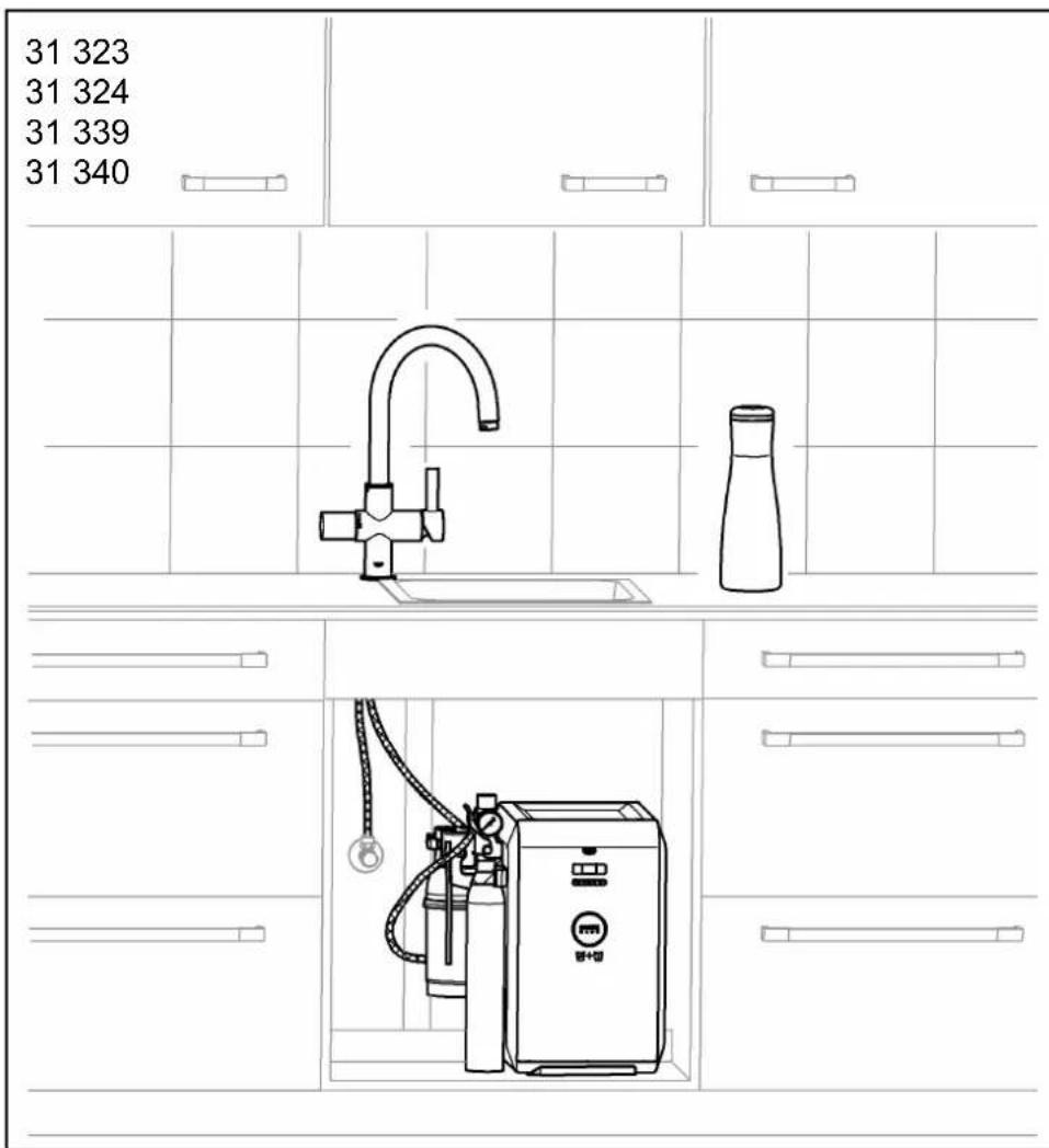
At the installation location, the cooler/carbonator, CO_2 cylinder and filter system must be protected from mechanical damage, heat and direct sunlight.
Do not install near heat sources or an open fire.
- The cooler/carbonator must be placed in an upright position.
- The cooler/carbonator must not be opened.
- Installation of the fitting and cooler/carbonator with filter cartridge is only permitted in frost-free rooms.
- The cooler/carbonator is only suitable for indoor use.
- Use only genuine replacement parts and accessories.
The use of other parts will result in voiding of the warranty and the CE identification, and could lead to injuries.
Technical data
Cooler/carbonator electrical data:
- Connection: Wall socket with earth wire, protected
via a 10 A fuse
Voltage supply: 230 V AC / 50 Hz
Max. power consumption: 270 W
Type of protection: IP21
- Relative air humidity: max.
- Refrigerant: 0.065 kg - R134a
- Safety shut-off of pump: approx. 4:30 min
Sanitary data:
- Cooler/carbonator cooled water capacity: 1.4 I
-
Flow pressure:
-
min. 0.1 MPa
recommended 0.2-0.5 MPa
- System operating pressure: max. 0.6 MPa
Test pressure of fitting: 1.6 MPa -
Flow rate at 0.3 MPa flow pressure
-
Fitting (tap water): approx. 9 l/min
-
Cooling/carbonator: approx. 2 l/min
-
Ambient temperature:
- Temperature
Fitting hot water inlet: max. 70^
-Recommended (energy saving): 60°C
-Cooler/carbonator water inlet: max. 20^
Cooled water temperature: approx. 5 - 10^
Sound pressure level LpA:
50 ± 4 dB
- Adjustable bypass, factory setting:
40%
Filter capacity at 40% bypass
litres
corresponds to max. 12 months
Water connection
cold - blue
-Fitting:
hot-red
- Cooling/carbonator: cold - blue
Electrical test data
Software class: A
Contamination class: 2
Rated surge voltage: 2,500 V
The test for electromagnetic compatibility (interference emission test) was performed at the rated voltage and rated current.
Approval and conformity

This product conforms to the requirements of the relevant EU guidelines.
The conformity declarations can be obtained from the following address:
Electrical installation

Electrical installation work must only be performed by a qualified electrician. This work must be carried out in accordance with the regulations according to IEC 60364-7-701 (corresponding to VDE 0100 Part 701) as well as all national and local regulations.
Installation
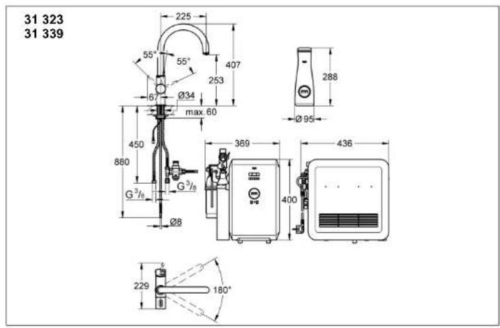
Refer to the installation dimensions on fold-out page I and II, Fig. [1].
Flush pipes thoroughly before and after installation (observe EN 806).
Install pressure-reducing valve on service valve, see fold-out page II, Figs. [2] to [4].
Install and connect fitting, see Figs. [5] to [7].
Important: The cable must not be pinched.
Install cooler/carbonator, see Figs. [1] and [8].
When transporting or installing the cooler/carbonator, cooling fluid may have run into the lines. In order to ensure that the cooling fluid has run back, the cooler/carbonator may only be switched on following a pause of 24 hours.
- A distance of at least 50mm must be maintained around the cooler/carbonator at all times.
- Adequate ventilation must be ensured. If necessary, provide ventilation grilles in the cover of the lower cabinet.
Install filter cartridge, see Figs. [9] to [12].
The filter head can be swelled forwards by up to 90^ in the wall holder to install the cartridge.
The wall holder can also be fastened directly to the lower cabinet or to the wall.
Connect cooler/carbonator, see Figs. [7] and fold-out page III, Fig. [13] to [16].
Open hot and cold water supply and check that connections are watertight.
Flush filter cartridge, see Fig. [17].
Press the flush button on the filter head in order to flush the filter system. Continue flushing until the water emerging from the hose is clear and free of bubbles (at least 2 litres).
Connect CO_2 cylinder, see Figs. [18] to [23].
Do not operate the valve on the back of the cooler/ carbonator as otherwise CO_2 will escape, see Fig. [19].
The valve is only needed when cleaning the cooler/carbonator.
Connect plug-in connector of fitting to plug-in connector of cooler/carbonator, see Fig. [24].
Establish voltage supply via mains plug, see fold-out page IV, Fig. [25].
The display illuminates and the remaining filter capacity is displayed in percent.
Operation / commissioning
Open lever in order to draw hot and cold tap water, see fold-out page IV, Fig. [26].
By turning handle, the carbon dioxide content of the cooled and filtered water can be changed:
-
Position OFF [display does not illuminate]
-
Position Chilled [display illuminates blue] = still water
- Position Medium [display illuminates turquoise]
= lightly carbonated water - Position Sparkling [display illuminates green] = strongly carbonated water
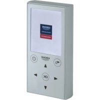
Control, see fold-out page IV, Fig. [27].
The buttons have the following functions:
Filter replacement reset
Filter size selection
Carbonate hardness adjustment
Display, see fold-out page IV, Fig. [27].
In the inactive state, the remaining filter capacity is displayed in percent.
Display of filter capacity in handle:
Flashing signal Meaning
| Filter capacity of more than 10% | |
| Filter capacity of less than 10% | |
| Order filter cartridge | |
| Filter capacity of less than 1% | |
| Change filter cartridge soon | |
| No filter capacity, Change filter cartridge Immediately |
The fitting has a system-related run-on time of approx. 1 second each time carbonated water is drawn. The display in the handle illuminates blue.
Set the temperature of the cooled, carbonated water on the cooler/carbonator, see fold-out page IV, Fig. [27].
Set carbonate hardness at filter head, see Fig. [28].
The relevant water supplier can provide information on the carbonate hardness.
Set carbonate hardness at bypass setting of filter head to local conditions, see table column A on fold-out page IV.
Display and setting of carbonate hardness on cooler/ carbonator, see table column B on fold-out page IV and Fig. [27].
O button for carbonate hardness adjustment:
- Press the button once: The display switches from the remaining filter capacity to the value currently set for the carbonate hardness.
- Keep the button pressed: After approx. 3 seconds, the value currently set for the carbonate hardness starts to flash.
- Release the button within the next 10 seconds: The value currently set for the carbonate hardness starts to flash.
Press the button and select the required value: C1: carbonate hardness 25-35 (bypass 20% -C2: carbonate hardness 18-24 (bypass 30%
-Factory setting:
C3: carbonate hardness 14 - 17 (bypass 40%
-C4:carbonate hardness 12-13 (bypass 50%
-C5:carbonate hardness 10-11 (bypass 60%
-C6:carbonate hardness 7-9 (bypass 70%
- Press and hold the button at the required value for 3 seconds:
The display of the value switches from flashing to continuous illumination and the value is set.
- Release the O button:
The remaining filter capacity is displayed again:
The litre capacity of the cartridge varies according to the water hardness set and the size of the cartridge, see table on fold-out page IV.
The cooler/carbonator of the GROHE Blue® fitting is set for operation with the 600 litre filter cartridge (Prod no.: 40 404) at the factory.
For operation with the 3,000 litre filter cartridge (Prod. no.: 40 412) or 1,500 litre filter cartridge (Prod. no.: 40 430), the cooler/ carbonator must be adapted.
Set the filter size, see Fig. [27].
button for filter size selection:
- Press button once. The display switches from the remaining filter capacity to the value currently set for the filter size.
- Keep the button pressed: After approx. 3 seconds, the value currently set for the filter size starts to flash.
- Release the button within the next 10 seconds: The value currently set for the filter size starts to flash.
- Press the button and select the filter size:
-F1:600 litres
-F2: 1,500 litres
-F3: 3,000 litres
- Press and hold the button at the required value for 3 seconds:
The display of the value for the filter size switches from flashing to continuous illumination and the filter size is set.
- Release the button: The remaining filter capacity is displayed again:
The fitting with cooler/carbonator is now fully installed and ready for operation.
Note: The various filter cartridges can be ordered at www.grohe.com.
Maintenance
Resetting filter capacity after changing filter cartridge, see fold-out page IV, Fig. [27].
□ button for filter replacement reset:
The remaining filter capacity is displayed:
- Press button
The display switches from the remaining filter capacity to rF. - Keep the button pressed:
After approx. 3 seconds, rF starts to flash. - Release the button within the next 10 seconds and press again:
rF flashes first and then illuminates continuously. - Release the button:
The remaining filter capacity is reset and then displayed again.
Restore factory settings, see Fig. [27].
Reset O buttons to factory settings:
- Press the buttons simultaneously: The display switches from the remaining filter capacity to PA.
- Keep the O button pressed:
After approx. 3 seconds, PA starts to flash.
- Release the O buttons within the next 10 seconds: First PA flashes, HC lights up and fitting and cooler/ carbonator must be synchronised with one another.
- Close handle and wait until the display in the handle illuminates green.
- Open handle fully until display in handle flashes green and water runs.
- Close handle.
The remaining filter capacity is displayed:
。
Important: Risk of dai
Always disconnect the power supply and interrupt the CO_2 supply before carrying out maintenance work on the system. The plug-in connector can then be disconnected, see fold-out page III, Fig. [24].
Inspect and clean all components and replace if necessary.
- Cartridge, see fold-out page IV, Fig. [29].
Assemble in reverse order. When installing the cartridge, ensure that the seals are correctly seated. Replace screw coupling and tighten.
II. Headpart, see fold-out page IV, Fig. [30].
Assemble in reverse order. Note the installation position of the stop and cable.
III. Mousseur (64 374), see fold-out page I.
Assemble in reverse order.
IV. Cleaning cooler/carbonator
For hygiene reasons, the cooler/carbonator must be cleaned once a year. Cleaning must be performed before changing the cartridge, in order to prevent contamination of the replacement filter cartridge.
Note: The cleaning kit (Prod. no.: 40 434) can be ordered at www.grohe.com.
Service
Note the Fault/ Cause/ Remedy table for information on eliminating problems.
If the problem cannot be rectified, interrupt the power supply to the cooler/carbonator. Note down the serial number of the cooler/carbonator on the rear of the device and consult a specialist installer or contact the GROHE Service Hotline via email under TechnicalSupport-HQ@grohe.com.
The GROHE Blue Chilled & Sparkling cooler/carbonator may only be repaired by GROHE Service.
Replacement parts
See fold-out page I ( ^ = special accessories).
Care
For directions on the care of this fitting, please refer to the accompanying Care Instructions.
Environment and recycling
Used filter cartridges can be returned to GROHE at the address for the relevant country, at www.grohe.com. However, the filter can also be disposed of hazard-free in domestic waste.
The accompanying CO2 cylinder can be refilled locally. The CO2 cylinder must not be sent back. At the end of its useful life it must be disposed of locally in accordance with applicable regulations.
Note: A 2 kg CO₂ cylinder (Prod. no: 40423) can be ordered at www.grohe.com.
The cooler/carbonator is an electrical device, to which return and take-back obligations apply in many countries. GROHE participates in such take-back systems in all relevant countries.
This category of device does not belong in the domestic waste, but must be disposed of separately in accordance with the relevant local national regulations.
| Fault Cause Remedy | ||
| Water not flowing · Water supply interrupted - Open shut-off valves | ||
| Filtered water not flowing, E1 flashes in the display | ·Water supply interrupted ·Pump switched off, display in handle flashes red | - Establish water supply to cooler/carbonator - Disconnect the power supply, wait 15 seconds and re-connect. |
| Filtered water is interrupted, E2 flashes in the display | ·Safety shut-off of solenoid valve for running time of over 4 minutes | - Close handle and open it again. |
| Filtered water does not flow, E3 or E4 flashes in the display | ·Cable or connector faulty - Contact Grohe | Service |
| Handle flashes orange, E8 flashes in the display | ·No filter capacity - Change filter cartridge immediately | |
| E5, E6, E7 or EE flashes in the display | ·Fault in cooler/carbonator - Contact Grohe | Service |
| Splashy, irregular flow | ·CO2content of water set incorrectly - Contact Grohe Service | |
| Indicator lamps do not flash/flash continuously | ·Control not recognised - Connect mains supply, disconnect plug-in connector, wait 30 seconds and reconnect | |
| No carbon dioxide in positions Medium and Sparkling | ·CO2cylinder not opened or empty - Fully open valve of CO2cylinder or replace cylinder |
F
ca. 9 l/min
ca. 2 l/min
C3: Karbonathardhet 14-17 (bypass 40%
- C4: Karbonathardhet 12-13 (bypass 50%)
- C5: Karbonathardhet 10-11 (bypass 60%
C6:Karbonathardhet 7-9 (bypass 70%
-
Position Chilled
-
Position Medium
-
Position Sparkling
[displayet]
[displayet
=iden kulsyre
[displayet lyser tyrkisblat]
C1: Carbonathardhed 25-35 (bypass 20%
-C2:Carbonathardhed 18-24 (bypass 30%
- Fabriksindstilling:
C3: Carbonathardhed 14-17 (bypass 40%
C4: Carbonathardhed 12-13 (bypass 50%
C5: Carbonathardhed 10-11 (bypass 60%
-C6:Carbonathardhed 7-9(bypass 70%
C3: karonathardhet 14 - 17 (bypass 40%
-C4:carbonbathardhet 12-13 (bypass 50% -C5:carbonbathardhet 10-11 (bypass 60%
-C6:karbonathardhet 7-9(bypass 70% )
= vahāhilihappoinen vesi
aal 1 aal alal alal alal alal alal alal alal alal alal alal alal alal alal alal alal alal alal alal alal alal alal alal alal alal alal alal alal alal alal alal alal alal alal alal alal alal alal alal alal alal alal alal alal alal alal alal alal alal alal alal
#
:a+1 1
A10jg 50/AC
270 1P21 575
R134a-0.065
A
1.41
MPa0.1 1
MPa0.5-0.2 4
MPa0.6 1
MPa1.6 1
MPa 0.3 Jyckd Jyckd Jyckd
12 120 C32-4
°C70 1234567890123456789012345678901234567890123456789012345678901234567890123456789012345678901234567890123456789
GROHE Blue Chilled & Sparkling
y j 1
aill 1
EN 1717 2
aill aall 111 111 111 111 111
C. C_6H_5CHO
paaa aae aee 1000000000000000000000000000000000000000000
13
aai jaii iiaai iai iai iai aai jaiiaai ay
yj yj yj yj yj yj yj yj yj yj yj yj yj yj yj yj yj yj yj yj yj yj yj
5 1
A
jaiy jay aal y jay aay jay aay
S OBC = S COD + S_ BOC
y
jai, jai, jai, jai, jai, jai, jai, jai, jai, jai, jai, jai
aaii
suee 2jiey
1y5 1
[23] [18] 15.247190000000000000000000000000000000000000000000000000000000000000000000000
[24] 150, 151, 152, 153, 154, 155, 156, 157, 158, 159, 160, 161, 162, 163, 164, 165, 166, 167, 168, 169, 170, 171, 172, 173, 174, 175, 176, 177, 178, 179, 180, 181, 182, 183, 184, 185, 186, 187, 188, 189, 190, 191, 192,
1.2.3
IV 1245678901011111111111111111111111111111111111111111
(,j)
()
(j)
auiiaaaaiy Saaie
(j)y
OFF
Chilled
Medium
Sparking
[27]JUIVyjIaIauaiuaiuuiuuiuuiuuiuuiuuiuuiuuiuuiuuiuuiuuiuuiuuiuuiuuiuuiuuiuuiuuiuuiuuiuuiuuiuuiuuiuuiuuiuuiuuiuuiuuiuuiuuiuuiuuiuuiuuiuuiuuiuuiuuiuuiuuiuuiuuiuuiuuiuuiuuiuuuuuuuuuuuuuuuuuuuuuuuuuuuuuuuuuuuuuuuuuuuuuuuuuuuuuuuuuuuuuuuuuuuuuuuuuuuuuuuuuuuuuuuuuuuuuuuuuuuuuuuuuuuuuuuuuuuuuuuuuuuuuuuuuuuuuuuuuuuuuuuuuuuuuuuuuuuuuuuuuuuuuuuuuuuuuuuuuuuUUUUUUUUUUUUUUUUUUUUUUUUUUUUUUUUUUUUUUUUUUUUUUUUUUUUUUUUUUUUUUUUUUUUUUUUUUUUUUUUUUUUUUUUUUUUUUUUUUUUUUUUUUUUUUUUUUUUUUUUUUUUUUUUUUUUUUUUUUUUUUUUUUUUUUUUUUUUUUUUUUUUUUUUUUUUUUUUUUUUUUUUUUUUUUUUUUUUUUUU
:jaiai jaiaiai jai
%10 10 jsl sluall s jsl %10 10 jsl sluall s jsl sluall a gls y llo %1 10 jsl sluall s jsl sluall a gls y slg y sluall a gls y sluall a gls y sluall a gls y sluall
04 14 25 26 27 28 29 30 31 32 33 34 35 36 37 38 39 40
y 100000000000000000000000000000000000000000000000000000000000000000000000000
a
A 2 2,500
aaiilie (laiaaii iaiy jai) yalianaygSll gill jaiai jai jai jai jai
aalaa
y 1

[30]K,IVyshnaiiAal 1
y
12jaiaiai (64374) Ⅲ
J111 14.520.1V
y
gaii 1
44 44 44
. www.grohe.com
aannn 1
GROHE Blue Chilled & Sparking
GROHE
(Audial)
aay
TechnicalSupport-HQ@grohe.com.
Nauhlichovaci chladici zaflzeni GROHE Blue Chilled & Sparkling smi opravovat pouze servisi sluzba GROHE.
Náhradní díly
viz skladacistrana I (^* = zvlastniprislusenstvi).
Osetrovani
(Dureza carbonatada 14 - 17 °DC):
max. 600 litres
corresponde a 12 meses no max.
Ligação da água
-Misturadora:
frio - azul
quente - vermelho
Carbonatador com radiador:
frio - azul
-F1:600 litrov
F2:1.500litroy
F3: 3,000 litroy
Tlacidlo podrzte pri pozadovanej hodnote na dobu 3 sekund:
Zobrazenia hodnoty velkosti filtra prechodza z blikania na trvalé svietenie a tato velkost filtra zostane nastavená.
- Tlaicidlo uvoInite:
Bb3MOxHa eeknloataaHa eHOpkoxBaTKOBata 6aTepe nC:
XnDpoakymyntopn
- IpoToCHN BOHOHaRpeBaTeJI N C TePMuH O npaBnHeHne
- PtoTOHn BOHOARpeBaTeHN CxHpaBmHNo ynpaBHeHne EKcHNOtauaC 6e3HApOpn Pe3eBoapn (OTbOpHn BOHOARpeBaTeHN) He e B3MOxHaI
ApMatypata GROHE Blue Chilled & Sparkling c HnterpinaH oxIaIaIeN I KAp6Obn3atop e IpeDaHa3NaHepa 3a yIOnTpe6a B Vacthne CekTop, a He B IpoPecOAnHnHa.
Финтbpнatura rnaBa e Cha6deHa C n3nTahн edHONOCOeH o6paTeH Klnanah.
ФИПТРБТЗВОДЕКЛСИФИЦИРСБЛСАСНEN1717 B KATEROPN2.
OxnaIeTnT, KOTo e cIeBpeMeHNO KAP6oHn3aTOp, pa60n C ekONOrnHa oxnaXdaa TeHocT.
Yka3aHHa 3a6e3onacHOCT

To3y uepe He npEHa3aHae3a ynOtpe6a ot NIIa (BkNIOv. Deua) c OprAHmEHn FmIaNeckc, CTeINBm INY mUCTBeHN cnoC6HOCTN n NO3HaHIA.
DetaTAPRA6Ba Da ca NOD HAD3Op 3a Da ce rapaHTnpa,Ye He IrpaTc ypeda.

Da ce n368Ra onachocTta ot nobpehen Ka6en.
Nobpehenite 3axpaHbauNi Ka6en Tp86ba Da
6bDat noDMeHNr OT pOni3BODntela Hn HerOBaTa
cepBnHa cnyKaHn OT cbTO TonKOba D6pe
KBAInnHnupao Nmue.

PnnoxehnT uencen (uekep Tn EF) e npedhaaehc amo 3aynoTpba c wkyko-KoHTAKTN (CEE7/4).

CO2(BBIIepeDn DByoknc) e r3n He Tpr6Ba da ce BIMuBA, CBIeCTByBA onaHcOT 3aDywaBAHe. H3non3BaIte cmo 6ytnk n C0, Do mKc. 2 Kr. FoneMHHa h Na nomuehenTo npn yonTp6Ba tM Tpr6Ba da e MHN. 13M

Bytnkata c CO2 e noJ hanyare. Ta Tp8ba da ce 3n03ba camo B n3npaBHe NOJOKHHe IN Tp8ba da 6bJe noCnIpyeHa 3a da He naHe.
Pa3peWeHa e EKcNPOatauHra t camo c npINOKeHHa aanTOp C MaHOMeTp.
OTXINHnEHnHaTnEDA TOKAcnITbPnA TCTeMa Tp6Ba Da ce nponme npedn pBpata yntpe6a.
PazpeuHHe e yonptepaba Ha cinnbphata ciCTeMa H3KNIOHTeHn CAMo CbC CTyeHa BOda 3a NITeHN HNYKdM.
ΦHnTbPHaTa Tnaba Tp86Ba Da ce CMeHN CneI 5 roDHH.
CbopbkeHHe He Tp8oBa Da ce TpaHcnpTnpa c npkaeHa 6yTuKa C CO2.
He Tnp8BaJa cEe M3BbPbUba CaMOBOPHO NOpDpBxKa IIN peMOHT Ha 6yTInKata C _2
- Pn noCTBaHe OxJaTEn-Kap6oHm3aToptb T uencenBt He Tp6Ba B HnKaKbB CnyaJ Da Ce MOKPrt.
OxndTeH-Kap60Hm3aTOpbT Tp8Ba Da e BKJIOHeH KbM KOHCTaHTHO en. 3axpaHBAhe.
- Oxanidien-kapboHn3aToptkKaTOn 6byInkata C CO2 nΦnIbPhATA CNCTeMa Tp8Ba Da 6bDat 3aUnTeHN Ha MACTOTO HA MOHTAK OMTexAHMHN NOBpei, TOINHa HnDpeKTHa CbHueBA CBETmHa. He Tp8Ba DA CE m3BbpWBA MOHTAK B 6bn30CT Do H3TOHHMn HA TOINHn Hn OTKnPT OFh.
OxndTeH-kapboH3aTOpbT Tp6Ba da ce nocTaBn BEPTNKAJIHO. - OxnaTeH-Kap6oHn3aTOpbT He Tp86Ba da ce OTBapra.
MOHTaKbT Ha apMatyPata N OXnAInTeN-KapBoHn3AtopacfNtBpeh KapTyUe pAspeHcMoBnOmeuHnBKO HToIe C bUeCTByBa ONaCHOT 3AmPb3BaHe.
OxlaTnIeH-ka60Hm3aToptbTe npedHa3NaueH cAmo 3a yNtpeBa B3aTbOpEH NnomeuHn.
I3nnon3BaiTe camo opunHHHn pe3epBNu qactn n npinnadJeKHOCTn. YNOTpe6aTa Na yUckn qactn BODn do 3ary6a Ha rapanHnraTa n CE 3na Ka CnrypHocT n MoKe da DoBeDe Do HaparHBAHnA.
TexHHueckn daHHN
EneKtpnueckn daHHN 3a oxJaNTeJI-Kap6oHn3aTopa:
Bpb3ka: CTeHEn en. KOHTaKT cBa 3aunTeH npoBODnIK, nOcMnpyen Ype3 10 A npedna3nteN
EneKtpo3axpaHbAhe:230VAC/50Hz
MaKc.MoUHOCT: 270W
3aunthactenen: IP21
- OTHOCNTENHABnAXHOCTHaBb3dyxa: MACK.75%
- Oxjkaa o cpeic TBO: 0,065 kr - R134a
- ABTomATNUHO N3KJIIOUBAHe HA NOMnata: npN6n.4:30 MNH
CaHnTapHo-TexHnueckn DaHHN:
-ObemHa oxlaedenaTboda BoxlaaTeIe-Kap6oHn3aTopa: 1,4
- Hanrahe ha notoka: - MHH. 0,1 MPa - npenopbUba ce 0,2-0,5 MPa
Pa60THo HAnrahe Ha cncTeMaTAt: MaKc.0,6 MPa
- N3NNTBaTeHnHaJIraHe Ha apMaTypata: 1,6 MPa
-Дебит рп 0,3 Мра налгаяне на Notoka
-Арматура (чесма на Вда): okolno 9 п/мен
-Охладител-kapбоннзатор: okolno 2 п/мен
- Cтайна Temпература: 4-32°C
- Temehepatya
- Ha topanata Boda npn BXoJa ha apMaTypaTa: MaKc. 70°C
- PpenopbUba ce (IxohomnHa eHeprIn): 60°C
-HaBoDATA npi BxOda Ha oxnadTEN-KapboHn3Atopa: MaKc. 20^ -Temnepatya HoxnadeHa TbOa: OKoN5-10°C
HINBOHa3BykaLpA: 50±4dB PEBVUPYEMbainacnactpoikaB3aBona: 40%
KanaunTeHaФnTbpa np4 40% BaHac (TBpOCT Ha BoData 14-17 ): MAKC.600 nITpa Baxn 3a MAKC.12 Mececa
BoonpoBOnHn Bpb3Kn ApMaTpya: CTyDHa-CnHn TOpna-YeRbHeA OxJaNTeN-Kap6oHN3aTOp: CTyDHa-CnHn
EneKtpueckn n3NTBaTeJIHn daHHN
Knaac Ha coopryepa:
CTeneHa3ambpcBaHe:
- I3MepBaTeHNo yDapHo HAnpeXeHne:
A
2
V
Cbbp3BaHe Ha 6yTnKata c CO, Bux Fm. [18] do [23].
He HATNCKAITE BENTHNA OT 3aHATA CTpHAA Ha oxNaHTEN-KAP6oHN3aTopa, B nPoTHBc Cnyau Ce ce n3yue CO2. BnKΦnir.[19].
BEHTINa e HEO6XoIMM cMo pRn NOChCTBaHe Ha OXNaITeJI-KAP60Ha3atOpA.
Cbpxte uencenHn HcEHNHTEN Ha apMAtypaT KaM uencenHn cEHNHTEN Ha oxNAdHTen-kap60H3atopa, BIKΦn.[24].
BknOuBaHe KbM eJekTpo3xaPbHaHTo qe3 uencena, BnK cTpaHua IV, pR. [25].
IcnncnCBETBAHOCtBtuNHMTKANauCTHTHaΦntbpa cceNokBaBHPOueHTN.
PObepkata HA nEeKpMaHTHnHATA cBbMecTHMOCT (PObepkA 3a N3lbvBaHTo H CmUaBaau CnHAnI) eN3bPpeHa Pn MAKcMMAnIO NOdABaHO HApexKeHne I TOK
Pa3peHHe 3a nycKaHe B ekCnloatauHa N deKnapaun 3a cBoTBeTcTBne

ToH npOyK T OTROBAPHa H3NCKBaHnHTa Ha CbOTBeTHHe HOpMn Ha EC.
Deknapaun 3a cbOTBETCTBNE MOrat da 6bDat Nmckan Ha cnednna anpec:
[OKa3aTeIaT CBeTN B 3eNeHO]
=CNHNOra3npaHaB0da
YnpabneHHe, BnK CTpaHnua IV, fM. [27].
BytonHcTeTaNMaTcneHnTe yHKuN:
□CMraHaHaΦnTbpa-Reset
△H3bpaHeHaDe6nTaHaΦnTbpa
HaCtpoika Ha TBbpOCTTa Ha BOdaTa
CunHann Ha dncnne, BIX cTpaHua IV, fnr. [27]
BcStbOHaHn oKoN octaTbHnT KanaUHTe H foNTba pa cNoKACA BpouEHTN.
TokaTeJ 3a kanaunTeHa hIITbpa Ha pBkoxBatkata:
Miraa ciHan
3HaYeHne

KanaunTet Ha mntbpa nobee
OT 10%

KanaTET Ha qntbpa no-Manko
or 10%

NopbauTe HOB KapTuW 3a FInTbpa
KanaaHTeHaΦnITbpaNo-MaIKoOT 1%
CMEHETECKOPOKAPTVUHa
fHbpa

Hama KaNaIeTHaΦnITbpa,
CMeHTe BeHara KaPTyHa Ha
fntbpa
HopMaHNo 3a CnCTeMATA OTTnAHe Na OTOKa CneB BcKo H3TOUBaHe Ha r3nHaBoa OKO1 oKeYHda, NOKa3aTeNtHa pKoXbATkata CBtHbO.
HactpoJaHa TeMnpaTypaHa HxJaDeHata,ra3npaHa BodaB OxnaJten-kap6oHn3aTopa,BKcTpaHnca IV, dur.[27].
HactpoKaHa TBpOoCTTa HA BoDTa pN HmTb.pHata rnaBa BnK CFIN.[28]
CTOHHOCHTNEHaTbBpDOCTTAHBOdAToMOraTaCaCeN3NCKATOTcBoTBETNHTEBOODCHAbNTENHΦnPMN.
HactpoIe KbM MEChTHe YcNoBn HA TbbpOCTTa HbData nocpeCTbOM peryIaTO Ha BaNACA Ha HnITbPHa rIABA, BIK KOHOKHATA B TabPiUa Hc TpaHNIu IV.
HactpoknHaTbPdoCTHaBODaHa oxnadntkap6oHn3aTopa, BIK Tabniata B Ha cTpaHn4V H mF. ByToHcO HAcptpoka Ha TbPdoCTHa B OdaTa:
HaHCHETe eHOKpAHO bTOHmEO O:
Ioka3aTeHrA Ha DCnJIe Ce I3MeHr OT cToHocCTTa HA
OCTaTbHHa KaNAHTet Ha FInPTbPa KbM TeKyuataT
CTOHOC H Ta TbPdOCTTa HA BOdata.
3aDpBxTe 6yToHcTe O:CnE npInb.3 cekyHn HacTpoeHa tOHOCT HaTBpbDOCTHa BODAta zAnOByda Mira.
PlycheTe 6yTOHHeTo O B pAMnTe Ha cIeBaunite 10 6ekHyndA AkyaIHO HAcTpoEHa TcOHT Ha TBpDOCTHa BOData MNA.
HATCHETE BYTOHHTO O H36peTe HEoBxDMMA tCtHOCT: C1:TbPDCtHa BOdTa 25-35 (6ainac 20% - C2:TbPDCtHa BOdTa 18-24 (6ainac 30%
- HacrpoKa B 3aOda: C3: TBpDoCT Ha BoDAta 14-17 (6ainac 40%) -C4:TbBpOCT Ha BoDAta 12-13 (6ainac 50%) -C5:TbBpOCT Ha BoDAta 10-11 (6ainac 60%) -C6:TbBpOCT Ha BoDAta 7-9 (6ainac 70%)
3AapbXkTe 3a 3ceyHn6byTOHHeO O npn Heo6xoImataCTOHOCT
TokaTeNATHCA TOnHOCTNTpeMHnabaOTMnAUBHEnpKbCHATO CBeTeU CNHn HToHOCTTaE hactpoeha.
- Nychete bytohyeO O: OctaTbYHnR KanaunTeC eNoka3Ba oTHBO. NITpOBnR KanaunTe H KaPTywa Bapnpa B 3abncmocT OT NaCTpoEhata TBbpOcT H BoDATA n pa3Mepa H KaPTywa, BIKK Ta6nUcaT H cTpaHua IV.
OxnaIeTJI-Kap6oHn3aTOpBJHa apMaTypArA GROHE Blue eHaCTpoEH b 3a0Ba 3a pa6oTa c 600 nIpya fIHTbpeH kaptyu (Kat.Nz:40.404).
PnE ecNnOaTaunC 3.000 nItpa fIHTbpEN KApTyU (KaT.Ne:40412) mIu I.500 nItpa fIHTbpEN KApTyU (KaT.Ne:40430), oxnaInten-Kap6OHm3aToptb Tpr6Ba da ce npHacTpOn.
HactpoikKa Ha DeBnta Ha fntbpa, BxK qnr. [27].
BytoHue 36npaHe Ha deBnHa HnTbpa
HaHCHETe eHOKpTaHO bTOHHTO △:Ioka3aTeiRt Ha DCnTne Ra 3MHeNr O T CToHocTtHaOCTaTHNRAKAnuTet Ha FInNTbPa KbM TeKyuataCToHocHTHa DeBnTa HFaONTPba.
3aDpBkTe 6yToHHeto △; CnE npBn. 3 cekynHn HAcTpoeHATA cToHOCHT Ha de6bTa ha pntbpa 3anoopa Da mira.
Plychete 6ytoHcTe rB pamKIne Ha CneBaunite 10 cekHyn: AkTyAnHO HAcTPOeHATA CTOnHOCT Ha DeBHTa HA PmTTbpa MMra.
HATINCHETe 6yTOHHTO AN36peTe DE6HTa HA pntbpa: F1:600 nTnPa
-F2: 1.500 mTpa
F3: 3,000 MTDA
3a#p6kTe 3a 3 cekyHn6byTOHHeTo △ npn Heo6xOuMaTa CToHOCt:
PokaTeTnHa CTOHOCTNE 3a DeBnTa HA FInbPa npemHnaba O T MrrAa H EnpeKbCaTO CBeTeu CmHan nDeBtHa H FAINbPa e HAcTPOeH.
PcHETe 6yToHHTo △ OctaHTbHHIT KanaIITet Ce nok3Ba OTHOBO. Cera apmatypata c oxnndTeN-kapboHN3atopae HNTACINPAH NTOBTA 3aeknnoataua.
Yka3aHHe:Pa3nMnHTeKapTyuHaΦnITbpaMorat Da ce NopbTuHa aDpec www.grohe.com.
TexHnuecko 06cnyXBaHe
Bb3ctahOBBaHae Hn pboHOaHnHte Ha cTPOKHa h octaTbHNHa kanaHTet Ha nIbpa cneD cmHa Ha kapyruA, buNK cTpAHMa IV, fNIR. [27].
ByToHue CmHa HaΦnTbpa-Reset:
OctaTbHnT KanaTET ce noka3Ba.
HATINCHETE 6yTOHcTeO□: Ioka3aTeIHa DaCnIeNce HcMHe OTCHOCTTHa OCTaTBuHHa KanaUHTe Ha cHITbpa KbM rF.
3aAepbke 8toHHTe0: Cnep np6n.3 cekynid rF 3aONBa da mna
- PHyCHETe 6yTOHHeTo BpaMKeTHe Ha cneDbauNte 10cekyHn Ito HATNCHETo OTHOBO: rF NpBPO MnRHa CNEbTOA CBETn HENpeKbChaTO.
- PycheTe 6yToHcTe Bb3ctaHOBarCe nbpBoHaayJIHnTe HAcTpoKIn nOCTATbHHNRT KAnauHTe HaΦnTTpa Ce NOK3Ba.
Bb3cTaHOBBaHe Ha npEpaBapTeHnHte HAcTpOKn 13BbPWeHN B 3aBoDa, BxKΦn.[27].
bYHToEHa △O Bc3TaHOBBAhe Na pIeDbapHTeINHTe HAcTpOnIK IN3bPueHN B 3A0Da?
HATINCHETEEOHBPEMEHO6yTOHTeTATA △O: Ioka3aTeIaI HA DCINNEe CE MHeNr OTHOcTTHa 0CTA1bHHNAKANITET HnNTbpa KbM PA.
3AaBxBe 6yOHTaT △O: Cnep npbN. 3 cekyn PA 3anaOBA da mRa
I\PycheTe 6byTOnEtata △OBpaMknTe Ha cnEeBauHte 10 cekynHn:
PbpoMnraPAHCCBETBnApMaTpyaNoxlaanTeKap60H3aToptbTpr6BaB3aMnHO da Ce CINxPOHmnpaT
3aTbOpete pkoKoBATKaTa nM3aKaJIte,doKATO NOKa3aTeNtA Na pkoKoBATKaTa CBeThe B 3eNEHO.
- OTBOpete pbKoXBaTKata Do KpaI, DOKaTO NOKa3aTeJrT Ha pbKoXBaTKata 3aNoUHe DA MURA B 3eNEHO BODATA NOTeH
- 3aTBOpTe pkoXbaTkata.
OctaBcHnT KanaunTe Ce noka3Ba.
BHHMaHHe!
Pnck ot nobpea!
Pn paobTu no noDpBxka Ha cbopbXeHneTo
obHKOBeHNO pBpO Tp8Ba Da ce N3KnIOuy enKtpo3axpaHbAHeto N da peKbCe npToka Ha CO2 CnE ToBA MoKe da c0cbO6be Te nCenHNA
cbeHNHTeBnKCTpaHuaI1I,ΦnR.[24]
Поверете BCИЧИ К actN, NOИСТЕТе Г И АКО e Heo6xOДиMo, Г ПОДМEHETe.
I. Kapryu, BIXK CTpaHnua IV, fNr.[29]
MOHTAXbT ce n3BpBa B 6opatha nocneobateHIOCT. Pn MoHTaKa Ha KapTuua BHIMABaTe yNtTHNTeIte Da npnrHerat npabuHIO. 3aBnHTe CbeDnHInTeI r 3aterHete.
II. NaTPOH, BIXK CTpaHnua IV, fHI.[30]
MOHTaBt Ce IaBbPbUa B o6paTH aocnedeobateHIOCT. CnBaBai Te NOnOKeHHeTo HA MOHTaK Ha orpAHHTeNIA Kabena! Ⅲ.YcNoKoKon (64374),BVK cTpaHnIa I.
MOHTaBcTe Me 3NbPbwa B o6paTha NocpeIobaeTneHOCT. IV. MoNTBaTaHc Ae XnApdUteN-Kap6OHN3atOpa
OT XHINHNHNA HneHa TOHkA OxNAdInTe-NKapBn3aTOpBT Tp8BaDA Ce noCTbBA BeDhBx BToDnHATA. POnCtBAHcTO p8BaDA Ce n3BbPUBa PpeD noDMAHHTa HA KApTyUa
3a Da He Ce 3aMbpcn pe3epBHHa HntbpeH KapTuW.
Yuka3aHne: KomJIeKtBJT 3a noUcIbTaBHe (Kat.Ne: 40 434) MÖGE Deutsche popuHa a Hapdec www.grohe.com.
CepBn3Ho 06cJyKBaHe
3aOTcpanhaBeHa np6IeMn Cb6IOdaBaTe Ta6NuaTa He3npaBHOCT/ PpUHnA/OTcpanhaBe.
Ako np6bemt He moke da bde OCTpaHEn, npekbchete enekp03axpaHbHeTo Ha oxnAdten-Kap6Oh3atOpa.
PpeniWte CEpHHN HOMep Ha oxnAdten-Kap6Oh3atOpa OT 3aHDTa CPTaHa HA yPeDa Hc ceObPhetE KbM cneuHaNCT NIN KOHTaPiApTe No eNkTPOHHata Noa cepBn3HATA NINHA GROHE Ha aDPEC TechnicalSupport-HQ@grohe.com
PaPeeH e pEmoHTb Ha oxnAdten-Kap6Oh3atOpa
GROHE Blue Chilled & Sparkling camo OT cepBn3Hata cnjx6a Ha GROHE.
Pe3epBn qactn
BnK CTpaHuaI ( ^ 一 = C n e u n a J H N q a c t h )
NoaPbXka
Yka3aHnHa 3a noDpBxKa Ha Ta3n apMaTy pMoKeTe Da HamePte B npNoXeHHeNt HcTpyKuIn 3a NoDpBxKa.
Ona3BaHe Ha OKoJIHaTa cpea n peuNKnIpaHc
N3non3BaHInTeΦnITbPnKapTyuCepnEmatO6paTHO TROGEHa3aDaeHnA 3a cbOTBeHTaCTpHa Ha www.grohe.com apec. HoT Meor Be3npB6mH0 Da Ce Ix3xBpIaR IN B 6tOBTuE OTnAdbu.
Mirgojoss signals Nozime

Characteristic electricity ractor-carbonator:
Racord: priză de perete cu conductor de protectie, protejata printr-o siguranta de 10 A
Tensiune de alimentare: 230 Vca / 50 Hz
Putere absorbita maxima 270W
Grad de protectie:IP21
- Umiditatea relativă a aerului: max. 75%
Agent frigorific: 0,065 kg - R134a
- Deconectare de siguranta pompa: dupa cca. 4:30 minute
Characteristicj tehnico-sanitare:
-
Apa răcitate in răcitor-carbonator: 1,4 I
Presiune de curgere: -
min. 0,1 MPa
- recomandat 0,2 - 0,5 MPa
Presiune delucru in system: max.0,6 Mpa
Presiune de incercare a baterie: 1,6 MPa
- Debit la presiune de curgere de 0,3 MPa
Baterie (apä de conducta): cca. 9 l/min
Racitor-carbonator: cca. 2 l/min
- Temperatura ambienta: 4 - 32°C
- Temperatura
-Intrare apacaldabaterie: max. 70^
- Recomandat (pentru economisire de energia): 60 °C
-Intrare apa ractor-carbonator: max. 20^
- Temperatura apei racite: cca. 5 - 10 °C
- Nivel de presiune acusticaA: 50±4 dB
- Bypass reglabil, reglaj din fabricà: 40%
Capacitate de filtrare la 40% bypass
(Duritate carbonica 14-17 KH): max.600 litri
C3: duritate carbonica14 - 17 (bypass 40%)
C4: duritate carbonica 12-13 (bypass 50% )
C5: duritate carbonica 10-11 (bypass 60%
-
C6: duritate carbonica 7 - 9 (bypass 70%)
-
Se mentione apasata tasta O temp de 3 secunde la valoarea necessara: indicarea valori trece de la afisare intermitenta la afisare continu a si noua valoare este reglata.
Se elibereazata tasta O:
Se afiseazainoucapacitatearezidualàfiltrului. Productivitatea litricarcartusulvariazinfunctioneduritatea reglataapeisi d'marimeacartusulia sevede tabeliudagina planta IV.
Din fabrica, racitorul-carbonator al bateriei GROHE Blue ^® este setat pe functionarea cu cartuș de 600 de litri
(nr. catalog: 40 404).
La fonctionarea cu cartusul de filtrare de 3.000 de litri (numar de catalogo 40 412) sau cu cartusul de filtrare de 1.500 de litri (numar de catalogo 40 430), racitorul-carbonator trebuie resetat.
Donycki BiIDNOBIDHICTbCTaHapTaM


LepnoDyKt 3aDoBbHRe BmUroBIOHIX nIeKTeNB C.
HaIcIcnATn 3aHITn HApTmAHCAeCepTIpKAcTbIP NO BIDIOBIDHCTb MOXHa 3a BkAaHOU HNKeE AnpeCOH.
CnID DOTpIMyBaTNC BCTaHOBJIbBHNx PO3MIPiB, WO Bk3aHI Ha CkNadaHmX apKyWax I lI, PnC. [1].
Peped BCTAHOBNEHnM I nCnra HbOro Heo6XidHO peteBnHO npomtnn CnCTemy TpybONpOBodIB (DOTPMYHTec EN 805)
BnKoHaTe MoHTax peykTopa TcKy Ha kyTObOMy BENTNI,INB.CknaDaHm apKyU II, pnc.[2]-[4].
BctahOBiB i niKKnOHTb 3mUyBaH, nB. pnc. [5]-[7]. Ybara! He moXHa 3aTnCKaTn Ka6eBb.
Po3auyIte oxonOxyBaay-kaep6oHiaTOp,IMB.pnc.[1]i[8].
IПдчТрансNotpyBaHnр/0P3a7uBHaHn oxoJxMyBaV-aKap6HizAtopaoXoJxOyBaJbHa piHnO MoKe NotpAnInDo Tpy6onBoPoiB. 3663neYHTN NOBE BNTiKaHHa OxOJxOyBaJbHOI pIDHn, OxOJxOyBaV-aKap6HizAtopCnD BMKnATn Nnne n24-0rOHNH opebpBn Bpo6Ot.
Длпnpавиьного розшуваньгя кокного 60kOу oxolokуBa-карбоHaTopa Mae 3aIMHHTCbBICTaHb He MeHue 50MM.
CniD 3a6e3neHTn DOCTaTHIO BEHTUNRJIO, 3a Heo6xIHHOCTI B 6bENy TymBn Heo6xIQHO BCTAHOBNTN BeHTUNRJIMHy peuITky.
BnKoHaIe MoTax fInbtpyBaIbHOrO KapTpIaXa, nVB. pnc.[9]-[12].
ПДСАМоТАКУМоКИХАнHINITIФиЛТРУВAILNYROBOYY HAcTlHOMY TpIMAHIdo 90° BNEpeD.
HaTHeHHn TpMaH MaOxHaTakOX pNkPInNTb 6e3NocepeHbO To yTMb a60 CTHi.
IIKnHtB OxonoMByaKap6oH3atop, nB.pnc.[7] icknaahn apkyu III,pnc.[13]-[16].
Bldkprnnoi npaoa rapaoyo Ta xonoAoHb Bodinpebipte 1nnhcbt cnKIB.
Ppomnte fIbtpyBaIbHn KapTpndK, nVB. pnc. [17].
HaTHCHITb KONKy npOMBAHnHa Na fIbtpyBaHbHI rOBoU, 106 npOMtN pIbtpyBaHbHy cIcTeMy.3JIChIOte npOec npOMBAHn,doKi 3IaHJHaHe NoUHe HAdXoDnT NcCTa Boga 6e3 6yIb6aWoK (IoHaHaMeHue 2 n).
PiéEHaHte 6aONi3 CO2,INB.pnc.[18]-[23].
He hatnckaIte Ha BiDkpIte Ha 3aHi CTOpOH
oxoJxByBa4-a-Kap60H3aTopa.Binomy pa3i CO_2 6yde
cnyuheHo, nB. pnc.[19].
LbeBldkpyteactoCobyctbIyIePiacOuHcENHa oxoJNkBya-kapBoH3atOpa.
3'eHnaiTe WTekePhe rH3do 3MiWbAyba 3i WTekePHm rH3dom OxonodKyBaaya-Kap6oHi3atopA, DnB. pnc. [24].
BIDHOBITbXINBHeHHa3aDOnOMoHOIOTencelHoBIJKN, DnB.CknaDaHn apKyu IV,pnc.[25].
YbIMKHeTbC DaIcIeJI, IBIO6Ba3NtCB 3aIINkoBA EMHICTb
fiBntBa y BIDcotXAK.
06cnyroByBaHHBBeDeHHBeknnyatauio
Bickpinte Baxinb, 06b yBimkHynn npaay xonoHoi Ta rapaoh BoDopnpoBIOHOBoN, DINB. CknaDaHH apkyu IV, pnc. [26].
NoBepHyBuyn pyuK. MoKHa 3mHITM BIMCT DBooky CYIByTneO BoXoJIOJIH bIbDInIbTpoBaHBI BOI:
- NOLOXKeHHoFF [IHdNkATOp He CbITNbC]
- NOJOKEHH Chilled [IHDAKATOP CBITNTbCnHIM KONbOpOM]
= Hera30BaHa Boga
- NOLOXKeHHa Medium [iHdNkATOp Cbitntb6ipko3OBm
KoJIbOpOM]
= TpiuKn ra3ObaHa B0da
- noNoKeHHa Sparkling [iHnKaTOp CbITnbc3eJIeHM
KoJIbOpOM]
=CNJbHOra3ObaHaBoDa
HanaTuBaHHa. nB.CknaDaHH an apKyu IV, pnc.[27].
KhONKn MaIOb 3a3HaueHi dani yHKu.
-ckndaHH3aueHHnicra3amHnphiBtpa
Bn6ipemHocTi pInbtpa
- HanaWtyBaHHKapboHaTHoI KOpCTKocT
Biodopaxhen HA nncnnei.BKnAaHmApkU IV, pnc. [27]. Y pekmi npoctoio Ha nncnnei BiodopaKaeTbca3anuKoBa CMHCTb cipntba y bICOTKxA.
IHdKaTOpu CMHOCTi pInbTpHa npuyi:
CBITIOBN CnHnI NoaHeHH

Bilbue 10 % emhocti fiinbtpa
MeHue 10% emHOCTI pInbtpa3amOBteinbtpyBaBnHkapTprJck

MeHue 1% emHOCTi pInbtpa Upe3e nnac zamHtB fInbTyBaBnH KAPTINK

EmHCTbfnIbtpaBmepnAo, fbnTpByaNbHHNkapTnpdk cnId 3aMHNblBpaay
B 3aekxocti BID nCCTEMNIICN KOKHOI NOdai BOIN,IO mICTb Dbooknc BytneO,3MIswBaU che npiaoc np6n.1 CEkyNDy, INHkAtoPb Na puY CBITNbCnIHIM KOJIbOpM.
BctahOBtIb Temnepatpy oxonodxhoIra3oBaHOI BOIN B oxonodxybai-Kap60hi3aTopi, INB. CKnaDaHNI apKyu IV,pnc.[27].
Haataynte kap6oHaty KOpctKicTB Ha pInbtpyBaIbHi IroNoBci, DnB. PnC. [28].
HΦopMaioI ΣOo KAP6oHaTHoI JoxpCTKoCTi MoxHa OTPMaTn y BiNobIOBHOBOJNOCTaHbNHka.
HanautyTe kap60aHTy XoPcTcIb H a BaJnAc fiinbtpyBaJIHOI roIobKn BiIOBIOHO Do MiCeBnx yMOB, DIB. CTOBTHK TaBNIU A h CKnaHOMy apkyUI V.
BCTaHOBIb KAP6OHAHTy XOpCTKlICTb B OXONoDjXyBaIc-Kap6OHi3aTopi, INB. CTOBnHk TabnU CaNtAHOMy apKyuI IV pnc.[27].
Khonka O dna hanaWtybaHHa KapboHaTHoJ kOpctKocti
HATNCHITb KHONky O: BIDo6paXeHHa Hdmcne3MInHTbC83 3aAMIIKOBOI eMOCTc fHtPa Ha NotoHHe BcTaHOBNeHE 3HAeHHa KAP6OHTHOJ XOPCTKCI.
HATNCHTaYtpmmyeKhONkyO:nicn np6n.3ceynd NOTOCHBCTAHOBNEHE3HAUEHHKAPBOHATOIJKOPCTKOCT NOHc 6NIMATM.
BidiNycttB KHONIKY O BnpoO8K HAcTynHnx 10 cekyHd: noTOHc BCTAHOBHe3HaueHHa KAp6oHaTHoi XOpCTKoCTi 6NIMATIME.
- HatinCHHT hONKY O i Bn6epBt NotpIbe 3aueHHe: C1: Kap6oHaTHa JoxpTcKtB 25-35 (6ainac 20%) C2: Kap6oHaTHa JoxpTcKtB 18-24 (6ainac 30%)
- BcTaHOBNeHe Bnpo6HnKOM 3HaueHHr:
C3: Kap6oHaTHa XopcTkicTb14-17 (6aunac 40%)
-C4: Kap60HaTHa KOpCTKicTb 12-13 (6aɪnac 50%)
-C5:Kap6oHaTHa KOpCTKicTb 10-11 (6aunac 60%)
C6:Kap60HaTHaXOPCTKICTB7-9(6ainac 70%)
HaTNCHTaYTPMMyTe KHO npRd 3NOTpiHMM 3HAeHHB NBPoDObK 3cckyH2: BIDo6paxEHH3MIHtBCr- 3HAeHHPnPiHHb 6NIIMMaI NOHc CBITINCR 6E3nepePBHO, OO 03HAAe yCUnHe BCTAHOBNEHH.
BidiNyctitb Khonky O:3HOBy Bidoopauntbca 3auiuKoBa emHictb pifibtpa.
JITropba noTyKHCTb KapTpNDja 3MHIHOeTcB 8aJIeKHOCTi BID BCTaOHBOHeIOI JopcTtOci BO Ta o6'My KaptPndka, DINB. TaNbNIO HA cnKaDnAHOMy apkuy IV.
Bipo6nHK HanaTbOye OxonAdKyBaV-kaKp6oH3aTOp 3mIyBa7a GROE Blue 已 ecKnpyaTuio qInIpyBaHoro kaptPrJa o6emOM 600 nIrpB (apTKyN 40 404).
IiJ qacekcnnyataui fInbtpybaIbnHoro Kaptnka
o6EMOM 3000 nIitpiB (apTKyn Ne: 40 412) a6o
o6EMOM 1500 nIitpiB (apTKyn N: 40 4390) Heo6xihno
nepenawtbyarO oxonodxybav-kapboH3atop.
BctahOBitb cHmictb pInbtpa, nB. pnc.[27].
Khoika △ДЯВБОРу EMHOCTI pTa:
HATMCHITb KONIKY△: BIDobpaKeHHHaDnCInTe 3MIHNbC3 3aNtUkoBOI EMHOCTi fiptna Ha NotOHe BCTAOBHeNE 3AHEHMe EMHOCTf IpItpa.
HATINCHITa ytpmye KNONKY△; nclra npn6.3 cekHy nOToHE BcTAHOBNE He 3aueHH eMHOCHT fInIgTpa NoHe 6mIMAtn.
BIDYtCTbHKONI △BNPOOBKaHctYNIHx106cKHyD NOHTO BCTAHOBHEMe 3AHHeHMeEMOHOTbIbTaBnIMMaTHe
- HatnCHtB KHONky A i Bn6epiB cMHicThb pIbTpA
-F1:600n
-F2:1500n
-F3:3000n
HaTNCHTaYtpmmyTe KhONkI nopA3 nOTpiHMM 3HAeHHM BnPOoBOK 3 cekyHd: BiO6paKeHH 3MiHTbc-3HaeeHHcMHOCTi pInbTa npnnHMH 6bnMaH iNoHe CbitINc4 63epepePBHO, O03HaaeyciHHe BCTAHOBHeHH.
BldnybIbO6paNTbc3aIIuKOBaEMHcTb cInbtpa. Tenep 3MiyBaYb4 0xOnoNdxyBaHem-KapboHa3atopON BCTaHOBNEo, i B1rTOBOmdoeknnyataqii.
Bka3iBkA. 3aMOBtu pi3HOMaHITI pifIbtpyBaIbHI kaTpNDK MoKHHa Ha Be6-caTI www.grohe.com.
Texhihe 06cnyrobyBaHHa
PcIa 3aIMHn fInbtpyBaIbHOro KapTpIaXa CkHbTe 3aIINKOby cMHIcTb fInbTa, dNb. cKJaHaHn apKyu IV, pnc.[27].
Khoika Dnna CkndaHn 3NaeHHn nicra 3amHn FInbTpa: BiDobpa3ntbCra 3anuWkoBa EMHicTB pInbTpA.
HaTNCHTb KHONky BIDOBpaKeHHa HuaCnnei 3MiHHTbc3 3aMikoboi cMHOCTi pInbTa ha rF.
- HaTnCHiB Ta yTpmyTe KhoNkY □
nicn np6n.3 ckynd rF noHne 6nMaTH.
BidiNycttbKhONkY BnpoObX HAcTyHnIX 10 cekyH, nicJyoro 3HOBy II HATNCHTb:
rF Cnoatky 6nMaTme, a NOTIM NOUHe CBITMCA NOCTIHO.
BidiNyctiib KhoNky 3aImKOBy eMHCt bIbtpa6yeCKHHyTO, a NOTIM BOHa 3HOBy BIDobpaunTcRa HdCnnei.
BIDHOIBTL BCTAHOBNEHBIPO6HNKOM 3HAUEHHN,INB.PMC.[27]. KHOIKI △,OII BIDHOBNEHHB CTAHOBNEHHX BIPO6HNKOM 3HAUEHb:
- OdHouacHO HaTnCHITb KHNKn □,△,O:
Biodo6paekehnHaNcPnei3MHNbC3aJIuKOB0E6MHOcti 61nptbaHpA.
HaTnCHiHbTa yTpMyTe KHOIIKIO,△,O:
nicra npn6n.3cekyH3HaehHH PA noHHe 6nmuTa.
BidiNycttb KHONK □,O BnpoD0BX HAcTyNHX 10 cekyH: PA cnoaHTky 6bNMaTMe,NOTIM NOHe CBiHTnC H,Cnicra Qoro 3MIyBaY Ta oxONkBya-Kap6oHi3atOp Heo6xHIO 6yde CnHXoH3yBatm Mk co6oH.
3akpntpe pyky Ta 3auekaite,doKn IHdkatop Ha pyu He 3acBtNTbCra 3eHHeM KOJbOpOM.
Повпсю Вдкрипгучky, ДOKИ ИДКИТОР ЗЕного Клььору на руци He noчhe 6имmaTи Ta He po3noHHeTBСя пода вody.
3akpnIe pyky.
BiO6pa3ntbca 3aIIuKoBAeMHicThb pIbTpA.
ybaral He6e3
Iiuc npoBeHn texHOrO 6cnyBoBaHH npctpo CnoaTuK Heo61DIO BMHNyTH XMHBeHH Ta neepktn Noay CO!nicra ToBO moXHa po3eHAnu WtKepeCNoChyEeH,INB.CknAadHn apkyu III, puc.[24] IpeBipTe,OnCTbe A60,AkuO Heo6xJHO,3AMHITb yci Detanl.
I. Kaptrpdk, INB. cklaDaHm apKyU IV, pnc. [29]. MoTAnK BID6yBaTeBc y 3BOPOTHI NocDiOBHOCTI. MoNTyOnH KApTrpdk, Heo6xIDO CTeKTHN 3a npABInbHM PC3aTuBbAHM yuJIbHbOaHbB. BCTabe TBnHtOBI kPInneHHra Ta3aBnHTITb IX do NOBHOf φikcauii.
II. BepxHa YactHa, nB. CKnadaHm apyU IV, pnc. [30]. MoTak BiDyBaETcB y 3BOpTHI NOCIOBHOCTI.
I. Aepatop (64 374), dVB. Kcnaadnayapkuyi!. MoTahK BldSyBaETcby aBOpOTHI noCIOBHOCTI.
IV. OuHcTbTe OxIoJOpKyBaV-Kap6oHi3aTOp
3 ririHnHm MipkyBaHb oxoJNDyBau-KapboH3aTOp Heo6xHIO
cHNTn OAMn PA3 Ha pik. OuHneHN CnI npOBoDnTI nepei
3AmHO KaptPdKa, 0o6 He 3a6pyDHTn 3aMHnn
fInbTpByabHnKapTpdxk.
Bka3iBa. KomnneK T nry ouuien H (apTuKyJ N: 40 434) MOxHa 3aMOBHT Ha Be6-caiTl www.grohe.com.
06cnyrobyBaHHa
IINBNIHNNPNO6NEMCKOPNCATAIECETA5JIUEIO3I CTOBNKNAMNHecnpabHcTB/IpnuHa/CnocioyHeHHA.
KIO np6nemy HmOxNBO BnIPHTB KINBEHNNHOXOkyBaH-kaPbOH3aTOpA.3AnuHTB Horo cepiHnHOMe, 0o BkA3aHo HAaHNI CTOPOH iPnCTPOI, i3EphHtCBsO CInocap-BoONpOBiDnKa A6o BiNpaTB eNEKtPOHNJNTcHa apecy rapaHoi nHII NTpMKN KomnaH GROHE
TechnicalSupport-HQ@grohe.com.
PeMoHTyBaTH oxoNoDxyBaH-Kap6oHi3atOp GROHE Blue Chilled & Sparkling DoaBnEeTbcI Ine CneUanIcTam cepicHoI cnyk6n GROHE.
3anyacTHH
INB. cknadn an apkyu I (^* = cneui) npnaia
Dorna
PekomeHdauii 0do DOrnay 3a UIM 3MIyBaem MicrTaBcB nocibny, 1o DoaTbcra.
BnNB Ha 3OBHic cepedobuue ytniia npodykty
KOMnai GROHE npmMaBnKOpNCTahi FInbTpYBaIbnHi kaTpndx BnyhKTx npnMy 3a BkazAHHMn Ha Be6-caTi www.grohe.com aDacemam y BiJNOBdHnx KpaIHax. Kpim TOrO, IX MoXHa TYtINbATn pao3m Is NoyTOBm CMTTm 63 uKOdn dnn 20BHIIbHO cepoDBuHa.
BaONH3CO2MOXHa NOBtOPO 3aOBHIOBaTH.
BanoHn 3 CO2 noBepaTn He notPi6HO. HanpiKniHi TePMHy ekCnnyatauix notPi6HO yTuNl3yBaTn BiNIOB1HO do MicueBHX npabn.
BkaibKa. BAnOH i3 CO2 06'EMOM 2 Kr (apTnKyn N: 40 423) MOKH3aMOBNTHaBe6-caiTi www.grohe.com.
OxonoJyBaay-Kap6oH3aTOp-ze eneKtpuHn npntpIi,Ha
Aky 8 barb0x kpaiaHax po3noBcDxyoTbc 06ob'akn 1ooBpeHH Ta pniHHTTA HaaD BkOpcNCTAHX npctpoIB.
B yicix bIDNoBDH KpaiaHax KomnaHg GROHE bepe yactb
y cmtexMxp npHHTT npntcPoIB Haaad.
PnncPoI 3ieIO no3HaKoHO 3a6OpOHeTbC8
BnKdAnPi pa30m i3 NobTOBMM CmTTTM.
Heo6xHIO yTIny3BytX bIDNoBIHO do YHHORO
3aKoHOdABCTBa Bawoi KpaIHn.
Donyck K 3KcNJIyatauH N COOTBETCTBNE CTaHdapTAM

Dahnoe H3dJnne yOOBnetBopert Tpe6oBaHnM COOTBeTCTByOuNX DnpeKtNB EC.
CepTnФнKaTbI COOTBETCTBnM OMOH0 3aIIPOcHTb NO yKa3aHHOMy HNKe aIpeCy.
HENOCpeCTBeHHO K Tymoe INN K CTeHe.
日 KdKnHoyntb oxaJadTbe-kaPbOHN3atop, cM. pNc. [7] nKraDnHIOH III, pC. [13]-[16].
OTKpbTuNoaayXoAoDhoNIOpRaeNoBdoI,npoBePrtb REpMeTHNOCTBu CoeIMHeHN.
PpombItb KaptpnDx KPhnBtpa, cm. pnc. [17].
He cneDyeT npNBOOHTb B DeIcTBnBe BeHTnB Ha
ObaTHoNIOBepxHocTNOxnaDnteJIa-Kap60H3aTopa,TaK
Kak B npOTHBOM cnyae npOnCxOaNT yIeTuYBaHne CO_2 Cm.pnc. [19].
BEHTINb Heo6xOdIM ToIbKo PnI CyCTKe OXlaIaNTeJIa-Kap60H3Atopata.
IopknIOHTb wTekepHb pa3bem Cmecntenr
COOTBETCTBYUeOpraHn3aUNN NO BODOCha6KeHHIO.
YcTaHOBnTb KapboHaTHyIO JKeCTKOCtB BQbl Ha BaInace rONOBKn
YcTaHOBnTb EMKoCTb FmNbTpA, CM. PnC. [27].
KhoNka R BbI6p EMMKocTn qnnbTpA:
HaxahtbQmHNpaKHOKNY△: H3o6paKeHHe HaCnIeNE MeHReTc C OCTaTOHNO nponyckHHe cnOco6HOCTn FnIBtPa HA TeKUeE yCTAHOBNeHHe 3HaHeHHe EMKOTn FInIBtPa.
PpOoHxab yepxmbb HAKATO KHONKY △: Pn6bn. Ype3 3 cekybl Tekyuye YcTaHOBNEHOOE 3HaHeHne EMKOCTH fNtBpa HauHAAET MmTb.
OTYCTTb KHONKY △B TEHHEME 10 nocDyHouXcKeyH2; Tekyuee yctaHOBNHeHoe 3nEHHeEMKcOHTpHaMfAet.
HaxaTb KHONky △n BBiBpaTb EMKOCtB pntbtpa
-F1:600NHTPOB
E2:1500 MTPOB
-F3:3000 nTPOB
-ПиТребуМOM3HAeHmYdEpKINBaTbHaxaToI KHOJky△3cekyHbI:
POKa3aHe 3HaeHnEMKOCtNΦnbltpaMeHReTCMIRaHnA Ha HneppeBbHOb CBeHHeN,EMKOCtBΦnbltpaYCTaHOBNeHa.
OTNYCTNTB KHONKY
CHOBAOTOPaKaAETCCHOTATOuHnAPonyckHnCNOc0bHOCTb dHnT
Tenebp CmeTeBc oJaxlanTeMeN-Kap6OHN3aTopOM HnCTANIPOBAHy I RTOBOb K pAbote.
PnmeuHane:PaanHHneKaprtndkxФnblrpoB MOxHO 3aKa3aTbNo aNepcYwww.grohe.com.
TexHmCheckoe 06cJyXnBaHne
C6poc octatouho nponycKHO cnocO6Hoctn qHbtpa nocne CMeHb KapTpNka qHbTpa, cm. cknaHoi JnCT IV, pnc.[27]. KHonka dans 6poca napametpoB nocne CMeHb qHbTpa:
OTo6paacr cct aotouhna nponyckha cnoc6hoctb fInnbta. Haxab kOnky
H3o6paKHeHnHaDmCnIeMeHReTcCocTeaHOH npOyckHO cnOCbOcHCTnФnBtpHa rF.
PpOtoKdAbyEepKbMaBhKaHAtOaKhoNky O: PnObl. Ypee3 3 cekyHbKhoNkaRf HauHaMe MHTRa.
OTNYCTHbKONIKYB THeHEnE 10nocJeDyUHXCEkyHn 3aTEM CHOBA HaxaTe ee: rF Chayana MInraet, a 3aTEM CBETNTC HEnpepbIHO.
OTNYCTNTB KHONKY□:IOKa3HHe octatoHno nponyckHO cnocobHO CTn HINbTa 6pcabSbaeTc, a nOTOM CHOBA OTObpaXaetcHa dnCnIee.
Bo3BpaK 3aBODcKNM yCTaHOBkAm, cm. pnc.[27]
IIaB03BpATAK3aBODCKIMYCTAHOBkAMCNEyETNCNOb3OBAtb KHOKN4 △O:
OJHOBpeMeHHaKaTb KHONK □△0:
N36paKeHHe Ha DCnIeee MeHReTc C cctatoHHO
nponyCckHncoc6oHctu FNbTa H a PA.
PnIbKn. 豫3 CekYbBA HkAaBIMKHOHKn △O:
OTNYCTNTH KHOHNK △OB THeHNE 10 NOcIeDyUOxINCKeYH2
PA MRAET BHAATE,HC CBETNTC. CMECNTB OXNAATNTB-KAP6OHN3ATOp HE06XoHIMO CINHXPOHN3IP0BA7b Dpyr C DpyROM
3aKpbItbpyknyIdoKdtaBcraNORBNEHn3eHOrO CBeHnE HBypck.
ПИПОТКБОТ OTKPBtBpyKU,ДОФДТСМУЕЗDESEHOPNIMDOKATOPAВPyueNNOCTYPENHNEBOVDI.
3aKpbTb pyHKy.
OTo6paxaetc octatoohar nponyckhna cnoocbhoctb nibtpa
BHHMaHHe!
Onachocb nanyehn nobpexdenH IpnTexHHeCKOMcbnyKbAHm CNCTMeBcRda He6xOdMIOKtIQyOHTbKTOUYH3JKeTpONITAHNA
n npekpaatab noady Cy C0 3aTeM MoXHO OTOeDHNHTB wTekehbl pa3bem, CM. CKTaNHOI NCT III, PMC. [24]. Bce Detan npOBeptB, OHCTNtB, pN HEO6xOIMOCIn 3aMeHHTB.
I. KaptpnDxK, CM, CKnAHOH NCT IV, PNC, [29]
MOnTaux npOa3B0DnTC B O6paTHoNocneObaTeNbHcToN. PIny cTaHOBe KAPrIaXCa CneINb 3a npABiMbHbIM NONOXHeMe yIpNoTHEHn.BBHTntb pe3b6oBoe coeHNHeMe n3aTReHyt b er oTo kKa3a.
II. KpaH-6yKca, CM. CKnAHOH JnCT IV, pnc. [30]
MOHTX npONBDOCTB B o6paTHOINOCNEBOATEbHOCTn. CooJIbAOBt yCTAHOBOOHoe NOIOKHEOEYnOpaN Ka6eIa
III.A3paTOp (64 374)CM.CKNaDHONJNCTI.
MOHTAK PNOBBOIDTC B O6paTHO NocNEOBaTeBbHOCTN. IV.OuchTka OxnAIneN-Kap6oHN3atOpa
HrIeHNHeckHX coobpaKeHH OXnAaITBeN-baKap6OHMaTOp Heo6xOmo OuHsTaOBn PA3 BToD, UToBbUcKnIOHTb 3aRpaHHe CMeHHORO KApTuDka QInbTpA,OChCTky CneJeYet BbIOHHTbe NpeD CMeHOH KApTuDka.
Пrimеаниме:Компгентд почсн (артокун №: 40 456) мохно Зakадь в Истор范围内 дусяс www.groho.de.
CepBnC
Pn yctpaheHnn npoBnem yuhtbBaTb Tabnuy HencnpaBhoctb / npnuHa / yctpaHeHne.
Ecnn np6bnemy He ydaetcnyctpaHntb,To moKHO OTKIOHHTB 3NeKTponNTaHHe OxnaTnEe-KapboHn3aTopa.CneNyET 3anHCatb CepnHbHm HOpE OxnaTnEe-KapboHn3aTopa, HaxoDnIiHaC H ObaPthO CTopone YCTpoNCTBa, N 6obpatncBcKaCTeHXNky INN KOHTAKTIPOBaT B ccpBnCHOn 1CnyKbNo ropeue nnHHGROHE no apdecy
TechnicalSupport-HQ@grohe.com.
PeMOT xnAaTnEaKap6OHaTaOpa GROHE Blue Chilled & Sparking paaepwaeTc BInONHbT bToBko CneuaanCTam cepBnCHOn cnyxkbkOMpanHn GROHE.
3anaHbIe yactn
CM.cknadnoiHcTl ( ^ 念 = ) cneuaIbHbIe npHaIeKHOCTN).
yxo
Yka3aHnno yxody 3a HactoIIM N3dEmeM npBedeHb B npNaraeMoHnCTpyKuIN.
Okpykaoua cpea n ytun3aun
IcnoIb3oBaHHBie KapTpndKn FInbTPOB nPHHMAOTcObpaTHO KOMNaHNe GROHE no aDecy dNra cooTBETCTBHOue cTpaHbI, CM. www.grohe.com Ho Ix TaKe MoKHO 6eOnaCHO yTHINHIOPOBaT bK Ka6 bTOBBe OTXoDbI.
HMeOuINcB KOMnIeKTe NoCTaBKn 6aIIOH CO2 MoXHO 3aONHrTb NOBTOHO.
Bo3Bpat 6aHNOH CO2 He npDyCMOTPN. Ho nCTeHnO cpoKa NOIb3OBAHnE rO heoXoHmO yTINHnIPoBaTB B COOTBETCTBN C MeTHBMn PnpNCAHmHN.
PpHmeaHHe: BaHnO HrA CO2BecOM 2Kr (apTmKyn N:40423) MoKHO 3aKa3aTb B IVItePHTe no aDpecy www.grohe.com.
OxnaTntb-kapboHn3aTOp RBnReTc3neKtpOyCtPoCTBOM,Ha KOTopo BO MHOrTH cTpaHAnPacnPoCTpAHHOTc683aHHoCTN B03BaPaIu npHHTMaOBpaTHo. KomnHaNG GROHE npHnMaTe yUCAHTe BO CBOETBCTByIOUChCTEmax npHHTMaYcTPOJCTB 6baTHo BO BCexpeNEBaHTbIX CTpaHax.

YcTpoCTBa CdaHbIM 063HaueHMe
HEOTHCATK B6tOBbIMTOxOaAM. OHNOXHBi
6bItyTNINMnPOBaHbB COOTBETCTBN
CnpdINCAHMM COOTBCTBHyOe CTpaHbI.
1230 Lakeshore Road East
Mississauga, Ontario
Canada, L5E 1E9
Tel.: +1 905 2712929
Fax:+19052719494
CH
Grohe Switzerland SA
Bauarena Volketswil
Industriestrasse 18
8604 Volketswil
Dhai Industrial Zone
P.O.Box 27048
1641 Nicosia
Tel.: +357 22 465200
Fax+35722379188
CZ SK
Grohe CR s.r.o.
Zastoupeni pro CR a SR
V Oblouku 104, Cestlice
252 43 Pruhonice
Tel.: +420 22509 1082
Fax: +420 22509 1085
www.grohe.com
2011/09/30
DK
GROHE A/S
Walgerholm 11
3500 Vaerlose
Tel.: +45 44 656800
Fax: +45 44 650252
E
GROHE Espana S.A.
C/ Botanica, 78
Gran Via L'H - Distr. Economic
08908 L'Hospitalet de Llobregat
(Barcelona)
Blays House, Wick Road
Englefield Green
Egham, Surrey, TW20 0HJ
Tel.: +44 871 200 3414
Fax: +44 871 200 3415
GR
N. Sapountzis S.A.
86, Kapodistriou & Roumelis Str.
142 35 N. Ionia - Athens
Tel.: +30 210 2712908
Fax: +30 210 2715608
H
GROHE Hungary Kft.
Roppentyu.53
1139 Budapest
Tel.: +361 238 8045
Fax:+3612380713
HR
GROHE AG - Predstavnistvo
Stefanovečka 10
10000 Zagreb
Tel.: +385 12989025
Fax:+38512910962
1
Grohe S.p.A.
Via Crocefisso, 19
20122 Milano
Tel.: +39 2 959401
Fax:+39295940263
IND
Grohe India Pvt. Ltd.
14th Floor
DLF Building No. 5, Tower A
DLF Cyber City, Phase III
Gurgaon - 122002
Haryana
Tel:+91 124 4933000
Fax: +91 124 4933 001
IS
BYKO hf.
Skemmuvegi 2
200 Kopavogur
Tel.: +354 515 4000
Fax: +354 515 4099
J
Grohe Japan Ltd
TRC Building, 3F
1-1 Heiwajima 6-chome, Ota-ku
Tokyo 143-0006
Tel.: +81 3 32989730
Fax: +81 3 37673811
N
GROHE A/S
Nils Hansens vei 20
0667Oslo
Tel.: +47 22 072070
Fax:+4722072071
NL
Eastern Mediterranean
Middle East - Africa
Area Sales Office
GROME Marketing (Cyprus) Ltd.
195B, Old Nicosia-Limassol Road
Dhai Industrial Zone
P.O.Box 27048
1641 Nicosia
Tel. +357 22 465200
Fax: +357 22 379188
Far East Area Sales Office:
GROHE Pacific Pte. Ltd
180Clemenceau Avenue
01-01/02 Haw Par Centre
Singapore 239922
Tel: +65 6311 3600
Fax:+6563780855
CROHE

ENJOY WATER