GCM 8 SJL - Saw BOSCH - Free user manual and instructions
Find the device manual for free GCM 8 SJL BOSCH in PDF.
User questions about GCM 8 SJL BOSCH
0 question about this device. Answer the ones you know or ask your own.
Ask a new question about this device
Download the instructions for your Saw in PDF format for free! Find your manual GCM 8 SJL - BOSCH and take your electronic device back in hand. On this page are published all the documents necessary for the use of your device. GCM 8 SJL by BOSCH.
USER MANUAL GCM 8 SJL BOSCH
natural_image
Mechanical cutting machine with a large blade and central blade assembly (no visible text or symbols)
GCM 8 SJL Professional
HEAVY DUTY

BOSCH
to Online Internet address
- Injini, leihe talmisu nl instrucioia originalea
The following table is in English:
bg Originals inструкция
The image is too blurry to recognize any text content.
la Potumjak-Potumjak und K. Ferrijguin-
B21 Offshore
Vangochung danso yang
English ...... page 23
Français......Page 35
text_image
Technical diagram of a mechanical assembly with numbered parts, likely from an engineering or manufacturing context.GCM 8 SJL
4
text_image
(38) (37) (36) (35) (34) (33) (39) (40) (41) (42)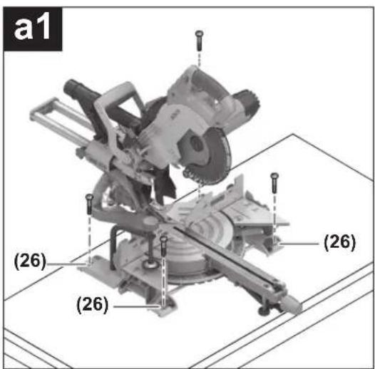
text_image
a1 (26) (26) (26)
natural_image
Mechanical assembly diagram showing a cutting machine with a highlighted cutaway view (no text or symbols)1 609 92A 4D3 | (30.08.2018) Bosch Power Tools
text_image
a3 (23)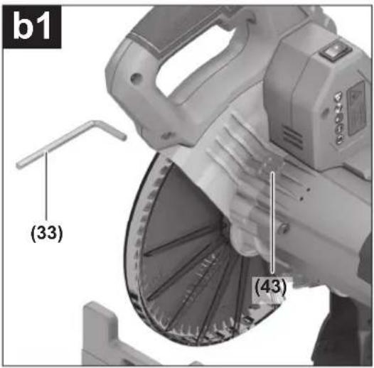
text_image
b1 (33) (43)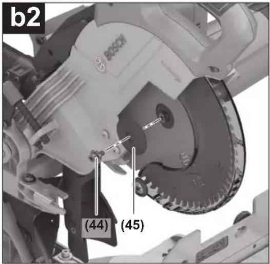
text_image
b2 (44) (45)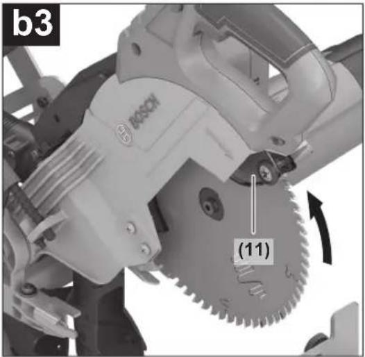
natural_image
Mechanical assembly diagram showing a Bosch motor with gear meshing and labeled component (11), no readable text or symbols beyond labels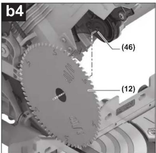
text_image
b4 (46) (12)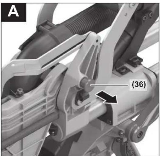
natural_image
Mechanical assembly diagram showing a motor with labeled parts and a numbered annotation (36), no readable text or symbols beyond the label.Bosch Power Tools 1 609 92A 4D3 | (30.08.2018)
6
text_image
B (13) ② ① (17)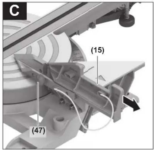
text_image
C (15) (47)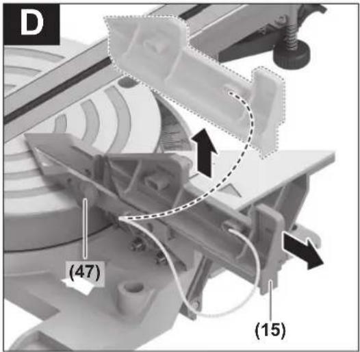
text_image
D (47) (15)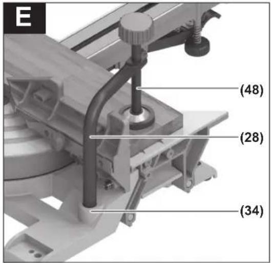
text_image
E (48) (28) (34)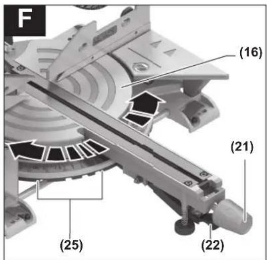
text_image
F (16) (21) (25) (22)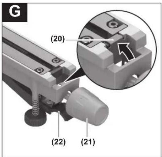
text_image
(20) (22) (21)1 609 92A 4D3 | (30.08.2018) Bosch Power Tools
text_image
H (39) 45° (29) (42) 0°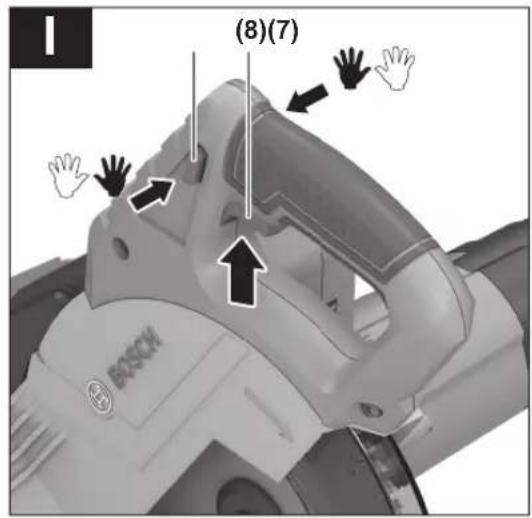
text_image
(8)(7) BOSCH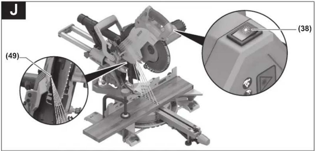
text_image
J (49) (38)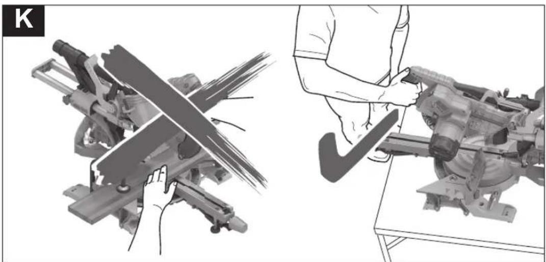
natural_image
Two-panel illustration showing a hand operating a cutting tool and another person adjusting a machine (no text or symbols present)Bosch Power Tools 1 609 92A 4D3 | (30.08.2018)
8
text_image
L (50) (19)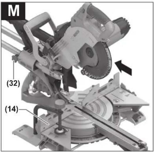
text_image
M (32) (14)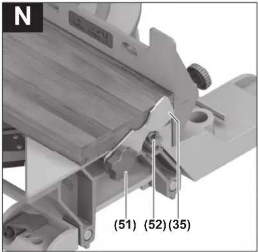
text_image
N (51) (52) (35)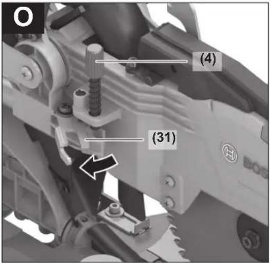
text_image
O (4) (31)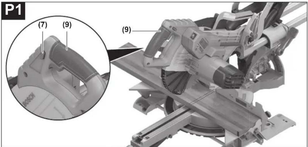
text_image
P1 (7) (9) (9) BOSCH1 609 92A 4D3 | (30.08.2018) Bosch Power Tools
text_image
P2 (53)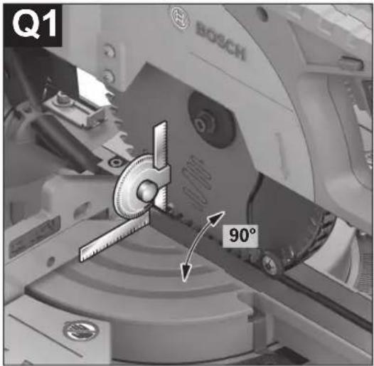
text_image
Q1 BOSCH 90°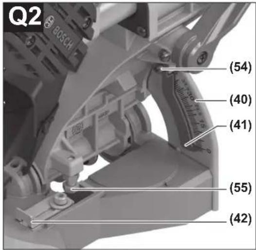
text_image
Q2 BOSCH (54) (40) (41) (55) (42)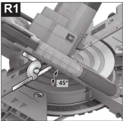
text_image
R1 45°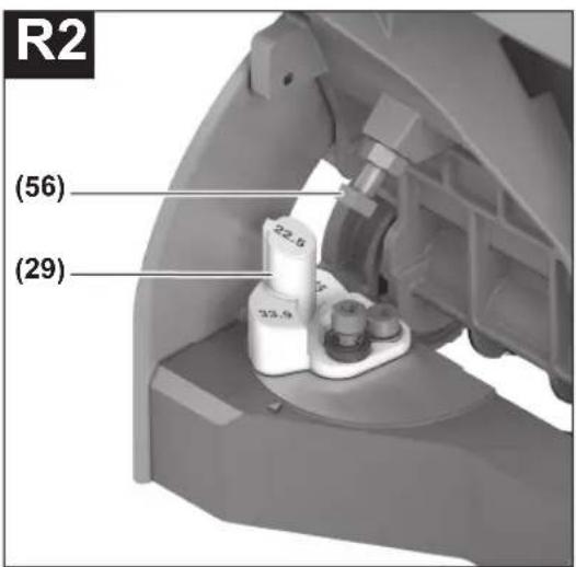
text_image
R2 (56) (29)Bosch Power Tools 1 609 92A 4D3 | (30.08.2018)
10
natural_image
Close-up of a Bosch industrial cutting machine with visible gears and control buttons (no text or symbols)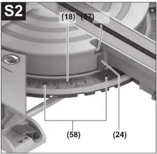
text_image
S2 (18) (57) (58) (24)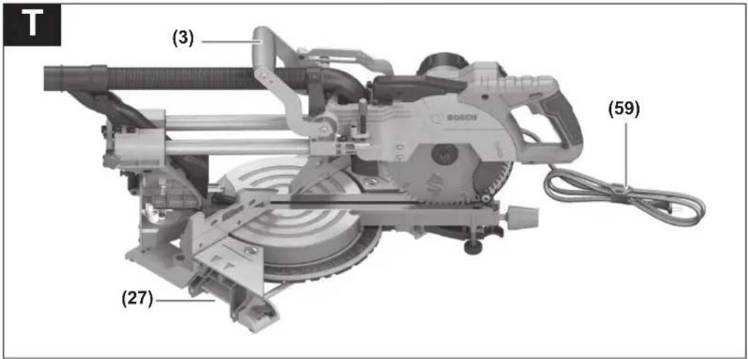
text_image
T (3) (59) (27)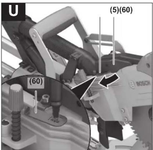
text_image
U (5)(60) (60) BOSCH1 609 92A 4D3 | (30.08.2018) Bosch Power Tools
Deutsch
Sicherheitshinweise
flowchart
graph TD
    A["Lock"] --> B["Up Arrow"]
    C["Unlock"] --> D["Down Arrow"]
Paneelsäge GCM 8 SJL GCM 8 SJL GCM 8 SJL GCM 8 SJL GCM 8 SJL
General Power Tool Safety Warnings
WARNING
Read all safety warnings, instructions, illustrations and specifica-
tions provided with this power tool. Failure to follow all instructions listed below may result in electric shock, fire and/or serious injury.
Save all warnings and instructions for future reference.
The term "power tool" in the warnings refers to your mains-operated (corded) power tool or battery-operated (cordless) power tool.
Work area safety
▶ Keep work area clean and well lit. Cluttered or dark areas invite accidents.
▶ Do not operate power tools in explosive atmospheres, such as in the presence of flammable liquids, gases or dust. Power tools create sparks which may ignite the dust or fumes.
▶ Keep children and bystanders away while operating a power tool. Distractions can cause you to lose control.
Electrical safety
▶ Power tool plugs must match the outlet. Never modify the plug in any way. Do not use any adapter plugs with earthed (grounded) power tools. Unmodified plugs and matching outlets will reduce risk of electric shock.
▶ Avoid body contact with earthed or grounded surfaces, such as pipes, radiators, ranges and refrigerators. There is an increased risk of electric shock if your body is earthed or grounded.
24 | English
▶ Do not expose power tools to rain or wet conditions. Water entering a power tool will increase the risk of electric shock.
▶ Do not abuse the cord. Never use the cord for carrying, pulling or unplugging the power tool. Keep cord away from heat, oil, sharp edges or moving parts. Damaged or entangled cords increase the risk of electric shock.
▶ When operating a power tool outdoors, use an extension cord suitable for outdoor use. Use of a cord suitable for outdoor use reduces the risk of electric shock.
▶ If operating a power tool in a damp location is unavoidable, use a residual current device (RCD) protected supply. Use of an RCD reduces the risk of electric shock.
Personal safety
▶ Stay alert, watch what you are doing and use common sense when operating a power tool. Do not use a power tool while you are tired or under the influence of drugs, alcohol or medication. A moment of inattention while operating power tools may result in serious personal injury.
▶ Use personal protective equipment. Always wear eye protection. Protective equipment such as a dust mask, non-skid safety shoes, hard hat or hearing protection used for appropriate conditions will reduce personal injuries.
▶ Prevent unintentional starting. Ensure the switch is in the off-position before connecting to power source and/or battery pack, picking up or carrying the tool. Carrying power tools with your finger on the switch or energising power tools that have the switch on invites accidents.
Remove any adjusting key or wrench before turning the power tool on. A wrench or a key left attached to a rotating part of the power tool may result in personal injury.
▶ Do not overreach. Keep proper footing and balance at all times. This enables better control of the power tool in unexpected situations.
▶ Dress properly. Do not wear loose clothing or jewellery. Keep your hair and clothing away from moving parts. Loose clothes, jewellery or long hair can be caught in moving parts.
▶ If devices are provided for the connection of dust extraction and collection facilities, ensure these are connected and properly used. Use of dust collection can reduce dust-related hazards.
Do not let familiarity gained from frequent use of tools allow you to become complacent and ignore tool safety principles. A careless action can cause severe injury within a fraction of a second.
Power tool use and care
▶ Do not force the power tool. Use the correct power tool for your application. The correct power tool will do
the job better and safer at the rate for which it was designed.
▶ Do not use the power tool if the switch does not turn it on and off. Any power tool that cannot be controlled with the switch is dangerous and must be repaired.
▶ Disconnect the plug from the power source and/or remove the battery pack, if detachable, from the power tool before making any adjustments, changing accessories, or storing power tools. Such preventive safety measures reduce the risk of starting the power tool accidentally.
▶ Store idle power tools out of the reach of children and do not allow persons unfamiliar with the power tool or these instructions to operate the power tool. Power tools are dangerous in the hands of untrained users.
- Maintain power tools and accessories. Check for misalignment or binding of moving parts, breakage of parts and any other condition that may affect the power tool's operation. If damaged, have the power tool repaired before use. Many accidents are caused by poorly maintained power tools.
▶ Keep cutting tools sharp and clean. Properly maintained cutting tools with sharp cutting edges are less likely to bind and are easier to control.
▶ Use the power tool, accessories and tool bits etc. in accordance with these instructions, taking into account the working conditions and the work to be performed. Use of the power tool for operations different from those intended could result in a hazardous situation.
▶ Keep handles and grasping surfaces dry, clean and free from oil and grease. Slippery handles and grasping surfaces do not allow for safe handling and control of the tool in unexpected situations.
Service
▶ Have your power tool serviced by a qualified repair person using only identical replacement parts. This will ensure that the safety of the power tool is maintained.
Safety Warnings for Mitre Saws
- Mitre saws are intended to cut wood or wood-like products, they cannot be used with abrasive cut-off wheels for cutting ferrous material such as bars, rods, studs, etc. Abrasive dust causes moving parts such as the lower guard to jam. Sparks from abrasive cutting will burn the lower guard, the kerf insert and other plastic parts.
▶ Use clamps to support the workpiece whenever possible. If supporting the workpiece by hand, you must always keep your hand at least 100 mm from either side of the saw blade. Do not use this saw to cut pieces that are too small to be securely clamped or held by hand. If your hand is placed too close to the saw blade, there is an increased risk of injury from blade contact.
The workpiece must be stationary and clamped or held against both the fence and the table. Do not feed the workpiece into the blade or cut "freehand" in any
way. Unrestrained or moving workpieces could be thrown at high speeds, causing injury.
▶ Push the saw through the workpiece. Do not pull the saw through the workpiece. To make a cut, raise the saw head and pull it out over the workpiece without cutting, start the motor, press the saw head down and push the saw through the workpiece. Cutting on the pull stroke is likely to cause the saw blade to climb on top of the workpiece and violently throw the blade assembly towards the operator.
▶ Never cross your hand over the intended line of cutting either in front or behind the saw blade. Supporting the workpiece "cross handed" i.e. holding the workpiece to the right of the saw blade with your left hand or vice versa is very dangerous.
Do not reach behind the fence with either hand closer than 100 mm from either side of the saw blade, to remove wood scraps, or for any other reason while the blade is spinning. The proximity of the spinning saw blade to your hand may not be obvious and you may be seriously injured.
Inspect your workpiece before cutting. If the workpiece is bowed or warped, clamp it with the outside bowed face toward the fence. Always make certain that there is no gap between the workpiece, fence and table along the line of the cut. Bent or warped workpieces can twist or shift and may cause binding on the spinning saw blade while cutting. There should be no nails or foreign objects in the workpiece.
Do not use the saw until the table is clear of all tools, wood scraps, etc., except for the workpiece. Small debris or loose pieces of wood or other objects that contact the revolving blade can be thrown with high speed.
▶ Cut only one workpiece at a time. Stacked multiple workpieces cannot be adequately clamped or braced and may bind on the blade or shift during cutting.
▶ Ensure the mitre saw is mounted or placed on a level, firm work surface before use. A level and firm work surface reduces the risk of the mitre saw becoming unstable.
▶ Plan your work. Every time you change the bevel or mitre angle setting, make sure the adjustable fence is set correctly to support the workpiece and will not interfere with the blade or the guarding system. Without turning the tool "ON" and with no workpiece on the table, move the saw blade through a complete simulated cut to assure there will be no interference or danger of cutting the fence.
▶ Provide adequate support such as table extensions, saw horses, etc. for a workpiece that is wider or longer than the table top. Workpieces longer or wider than the mitre saw table can tip if not securely supported. If the cut-off piece or workpiece tips, it can lift the lower guard or be thrown by the spinning blade.
▶ Do not use another person as a substitute for a table extension or as additional support. Unstable support for the workpiece can cause the blade to bind or the
workpiece to shift during the cutting operation pulling you and the helper into the spinning blade.
The cut-off piece must not be jammed or pressed by any means against the spinning saw blade. If confined, i.e. using length stops, the cut-off piece could get wedged against the blade and thrown violently.
▶ Always use a clamp or a fixture designed to properly support round material such as rods or tubing. Rods have a tendency to roll while being cut, causing the blade to "bite" and pull the work with your hand into the blade.
▶ Let the blade reach full speed before contacting the workpiece. This will reduce the risk of the workpiece being thrown.
If the workpiece or blade becomes jammed, turn the mitre saw off. Wait for all moving parts to stop and disconnect the plug from the power source and/or remove the battery pack. Then work to free the jammed material. Continued sawing with a jammed workpiece could cause loss of control or damage to the mitre saw.
▶ After finishing the cut, release the switch, hold the saw head down and wait for the blade to stop before removing the cut-off piece. Reaching with your hand near the coasting blade is dangerous.
▶ Hold the handle firmly when making an incomplete cut or when releasing the switch before the saw head is completely in the down position. The braking action of the saw may cause the saw head to be suddenly pulled downward, causing a risk of injury.
- Keep your work area clean. Material mixtures are particularly hazardous. Light metal dust may catch fire or explode.
▶ Do not use dull, cracked, bent or damaged saw blades. Unsharpened or improperly set saw blades produce narrow kerf causing excessive friction, blade binding and kickback.
▶ Do not use saw blades made from high speed steel (HSS). Such saw blades can easily break.
▶ Always use saw blades with correct size and shape (diamond versus round) of arbour holes. Saw blades that do not match the mounting hardware of the saw will run off-centre, causing loss of control.
▶ Do not replace the integrated laser with a laser of another type. A laser that is not compatible with this power tool could pose a risk to persons.
▶ Never remove cuttings, wood chips, etc. from the cutting area while the power tool is running. Always guide the tool arm back to the neutral position first and then switch the power tool off.
▶ Do not touch the saw blade after working before it has cooled. The saw blade becomes very hot while working.
▶ Never make warning signs on the machine unrecognisable.
Products sold in GB only:
Your product is fitted with an BS 1363/A approved electric plug with internal fuse (ASTA approved to BS 1362).
26 | English
If the plug is not suitable for your socket outlets, it should be cut off and an appropriate plug fitted in its place by an authorised customer service agent. The replacement plug should have the same fuse rating as the original plug.
The severed plug must be disposed of to avoid a possible shock hazard and should never be inserted into a mains socket elsewhere.
The power tool is delivered with a warning sign (see table: "Symbols and their meaning").

Do not direct the laser beam at persons or animals and do not look directly into the laser beam or at its reflection. Doing so could lead to blindness, or could cause acci-
dents or damage to the eyes.
▶ If laser radiation hits your eye, you must close your eyes and immediately turn your head away from the beam.
▶ Do not use any optical instruments such as binoculars to view the radiation source. Doing so can damage your eye.
▶ Do not direct the laser beam at persons who are looking through binoculars or similar instruments. Doing so can damage their eye.
▶ Do not make any modifications to the laser equipment. The setting options described in these operating instructions can be used safely.
Symbols
The following symbols may be important for the operation of your power tool. Please take note of these symbols and their meaning. Correctly interpreting the symbols will help you to operate the power tool more effectively and safely.
Symbols and their Meaning
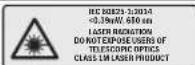
Laser radiation Do not view directly with tele- scopic optical probe Laser class 1M

Keep hands away from the cutting area while the power tool is running. Contact with the saw blade can lead to injuries.

Wear a dust mask.

Wear safety goggles.
Symbols and their Meaning

Wear hearing protection. Exposure to noise can cause hearing loss.

Danger area! Keep hands, fingers or arms away from this area.

The adjustable fence must be pulled outward when sawing mitre/bevel angles.
The free end of workpieces must be supported with saw table extensions.

ø 30 mm
Take note of the dimensions of the saw blade. The hole diameter must fit the tool spindle without play. If it is necessary to use reducers, ensure that the dimensions of the reducer are suitable for the base blade thickness and the saw blade hole diameter, as well as the tool spindle diameter. Wherever possible, use the reducers provided with the saw blade.
The saw blade diameter must match the information specified on the symbol.
flowchart
graph TD
    A["↑"] --> B["↓"]
    C["←"] --> D["↑"]
    E["↓"] --> F["←"]
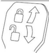
Clamping lever closed: The adjusted bevel angle of the tool arm is held in place.
Clamping lever open: Bevel angles can be adjusted.
Product description and specifications

Read all the safety and general instructions. Failure to observe the safety and general instructions may result in electric shock, fire and/or serious injury.
Please observe the illustrations at the beginning of this operating manual.
Intended use
The power tool is intended as a stationary machine for making straight cuts in wood with and against the grain. It is possible to cut mitre angles of -52^ to +60^ and bevel angles of -2^ to +47^ .
The power tool is designed with sufficient capacity for sawing hardwood and softwood as well as chipboard and fibre-board.
When using appropriate saw blades, sawing aluminium profiles and plastic is also possible.
Product features
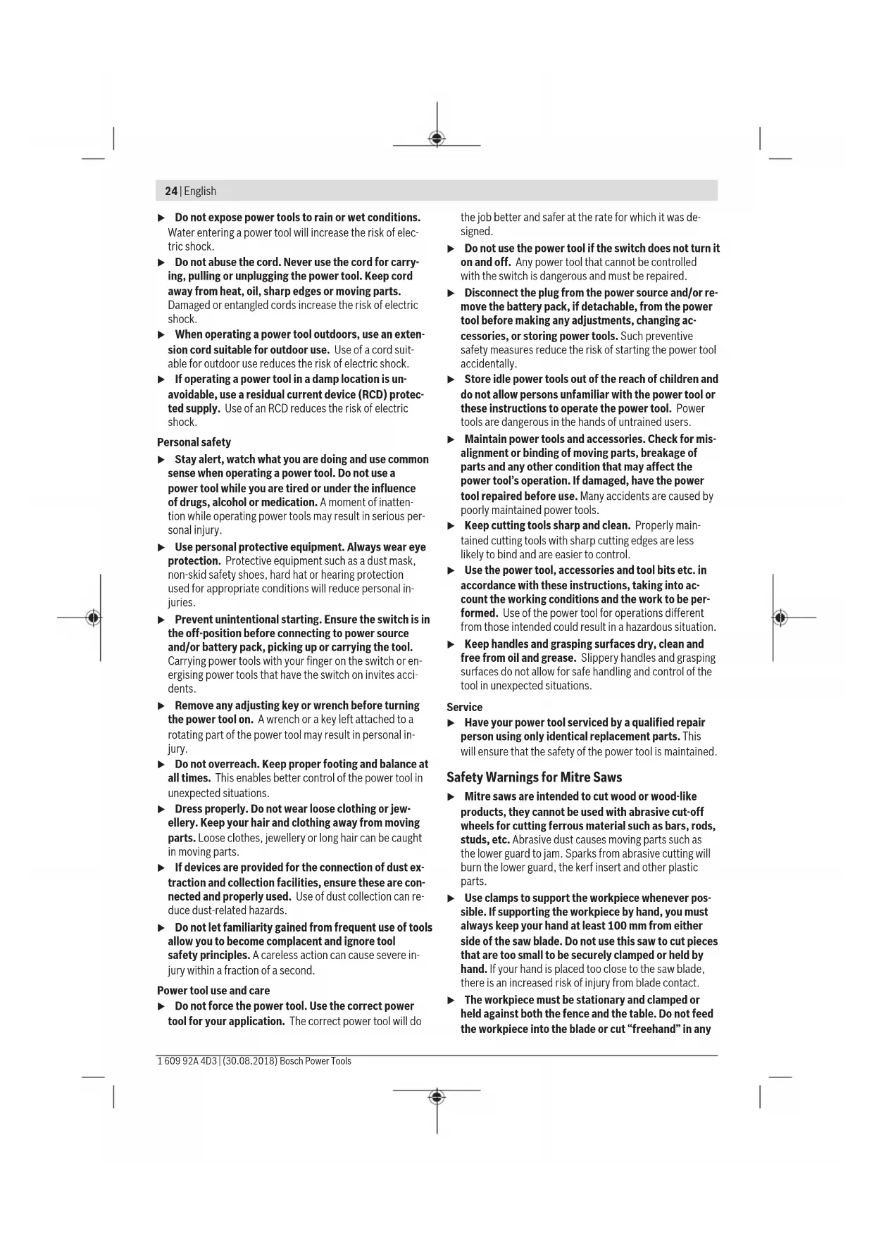
The numbering of the product features refers to the diagram of the power tool on the graphics page.
(1) Slide device
(2) Chip ejector
(3) Transport handle
(4) Adjusting screw of depth stop
(5) Laser protection cap
(6) Roller
(7) Lock-off switch for on/off switch
(8) On/off switch
(9) Handle
(10) Protective guard
(11) Retracting blade guard
(12) Saw blade
(13) Saw table extension
(14) Fence
(15) Adjustable fence
(16) Saw table
(17) Clamping lever of the saw table extension
(18) Scale for mitre angle
(19) Insert plate
(20) Locking clamp
(21) Locking knob for all mitre angles
(22) Mitre detent lever
(23) Tilt protector
(24) Angle indicator for mitre angles
(25) Detents for standard mitre angles
(26) Mounting holes
(27) Recessed handles
(28) Screw clamp
(29) Standard bevel angle stops 45°, 22.5° and 33.9°
(30) Chip deflector
(31) Depth stop
(32) Locking screw for slide device
(33) Hex key (5 mm)
(34) Holes for screw clamp
(35) Length stop ^4
(36) Transport safety lock
(37) Laser warning label
(38) On/off switch for laser (cutting line indication)
(39) Clamping lever for all bevel angles
(40) Scale for bevel angle
(41) Angle indicator for bevel angles
(42) Stop for standard 0^ bevel angle
(43) Spindle lock
(44) Hex socket screw for mounting of saw blade
(45) Clamping flange
(46) Interior clamping flange
(47) Locking screw for the adjustable fence
(48) Threaded rod
(49) Laser beam outlet aperture
(50) Screws for insert plate
(51) Locking screw for length stop ^A)
(52) Clamping screw for length stop ^A)
(53) Set screw for laser position (parallelism)
(54) Screw for bevel angle indicator
(55) Stop screw for 0^ bevel angle
(56) Stop screw for 45^ bevel angle
(57) Screw for mitre angle indicator
(58) Set screws for mitre angle scale
(59) Hook-and-loop strap
(60) Laser lens cover
A) Accessories shown or described are not included with the product as standard. You can find the complete selection of accessories in our accessories range.
Technical data
| Sliding mitre saw GCM 8 SJL GCM 8 SJL GCM 8 SJL GCM 8 SJL GCM 8 SJL | ||
| Article number | 3 601 M19 161 3 601 M19 1.. 3 601 M19 1C1 3 601 M19 1813 601 M19 1B13 601 M19 1K1 | 3 601 M19 1413 601 M19 1L1 |
| Rated power input W 1250 1600 1250 1400 1600 | ||
| No-load speed rpm 5600 5600 5600 5600 5600 | ||
| Starting current limitation | ●●●●● | |
Bosch Power Tools 1 609 92A 4D3 | (30.08.2018)
28 | English
Sliding mitre saw GCM 8 SJL GCM 8 SJL GCM 8 SJL GCM 8 SJL GCM 8 SJL
| Laser type nm 650 650 650 650 650 | ||||||
| mW < 0.39 < 0.39 < 0.39 < 0.39 < 0.39 | ||||||
| Laser class 1M 1M 1M 1M | ||||||
| Divergence of laser line | mrad (full angle) | 1.0 | 1.0 | 1.0 | 1.0 | |
| Weight according to EPTA-Procedure 01:2014 | kg 17.3 | 17.3 | 17.3 | 17.3 | 17.3 | |
| Protection class / II / II / II / II / II | ☐ | ☐ | ☐ | ☐ | ☐ | |
| Dimensions of suitable saw blades | ||||||
| Saw blade diameter | mm 216 | 216 | 216 | 216 | ||
| Base blade thickness | mm 1.3-1.8 | 1.3-1.8 | 1.3-1.8 | 1.3-1.8 | 1.3-1.8 | |
| Max. cutting width mm 3.3 | 3.3 | 3.3 | 3.3 | 3.3 | ||
| Hole diameter mm 30 | 30 | 25.4 | 25.4 | 25.4 | ||
Permissible workpiece dimensions (see "Permissible workpiece dimensions", page 32)
The specifications apply to a rated voltage [U] of 230 V. These specifications may vary at different voltages and in country-specific models.
Noise information
Noise emission values determined according to EN 62841-3-9.
Typically, the A-weighted noise level of the power tool is: Sound pressure level 99 dB(A); sound power level 112 dB(A). Uncertainty K = 3 dB.
Wear hearing protection
The noise emission value given in these instructions has been measured in accordance with a standardised measuring procedure and may be used to compare power tools. It may also be used for a preliminary estimation of noise emissions.
The noise emission value given represents the main applications of the power tool. However, if the power tool is used for other applications, with different application tools or is poorly maintained, the noise emission value may differ. This may significantly increase noise emissions over the total working period.
To estimate noise emissions accurately, the times when the tool is switched off, or when it is running but not actually being used, should also be taken into account. This may significantly reduce noise emissions over the total working period.
Assembly
▶ Avoid starting the power tool unintentionally. The mains plug must not be connected to the power supply during assembly or when carrying out any kind of work on the power tool.
Items included
Check to ensure that all the parts listed below have been supplied before using the power tool for the first time:
- Sliding mitre saw with mounted saw blade
- Screw clamp (28)
- Hex key (33)
Note: Check the power tool for possible damage.
Before continuing to use the power tool, carefully check that all protective devices or slightly damaged parts are working perfectly and according to specifications. Check that the moving parts are working perfectly and without jamming; check whether any parts are damaged. All parts must be fitted correctly and all the conditions necessary to ensure smooth operation must be met.
If the protective devices or any parts become damaged, you must have them repaired or replaced by an authorised service centre immediately.
Stationary or flexible mounting
▶ To ensure safe handling, the power tool must be mounted on a flat, stable work surface (e.g. work bench) before use.
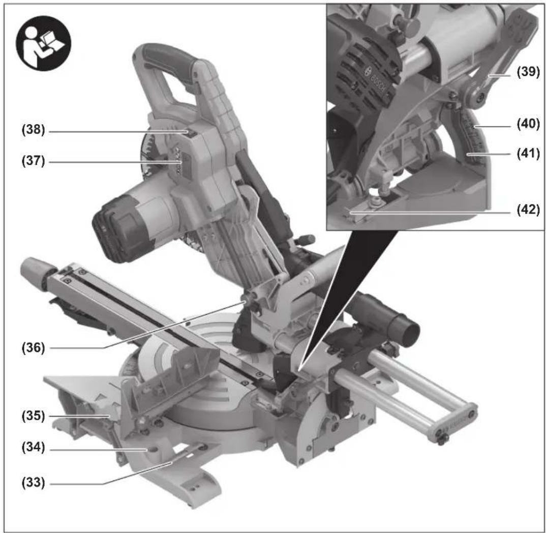
Mounting on a work surface (see figures a1-a2)
- Use suitable screw fasteners to secure the power tool to the work surface. Use the holes (26) to do this.
or
- Firmly clamp the base of the power tool to the work surface with commercially available screw clamps.
Mounting on a Bosch saw stand
With the height-adjustable legs, Bosch GTA saw stands provide firm support for the power tool on any surface. The
workpiece supports of the saw stand are used for underlay- ing long workpieces.
Read all the warnings and instructions included with the saw stand. Failure to observe the warnings and follow instructions may result in electric shock, fire and/or serious injury.
▶ Assemble the saw stand properly before mounting the power tool. Correct assembly is important to prevent the risk of collapsing.
- Mount the power tool on the saw stand in the transport position.
Flexible installation (not recommended) (see figure a3)
If, in exceptional circumstances, it is not possible to mount the power tool on a flat and stable work surface, you can improvise by setting it up with the tilt protector.
▶ Without the tilt protector, the power tool will not be stable and can tip over especially when sawing maximum mitre and/or bevel angles.
- Rotate the tilt protector (23) inwards or outwards until the power tool is positioned straight on the work surface.
Dust/chip extraction
The dust from materials such as lead paint, some types of wood, minerals and metal can be harmful to human health. Touching or breathing in this dust can trigger allergic reactions and/or cause respiratory illnesses in the user or in people in the near vicinity.
Certain dusts, such as oak or beech dust, are classified as carcinogenic, especially in conjunction with wood treatment additives (chromate, wood preservative). Materials containing asbestos may only be machined by specialists.
- Use a dust extraction system that is suitable for the material wherever possible.
- Provide good ventilation at the workplace.
- It is advisable to wear a P2 filter class breathing mask.
The regulations on the material being machined that apply in the country of use must be observed.
- Avoid dust accumulation at the workplace. Dust can easily ignite.
The dust/chip extraction system can be blocked by dust, chips or fragments of the workpiece.
- Switch the power tool off and pull the mains plug out of the socket.
- Wait until the saw blade has come to a complete stop.
– Determine the cause of the blockage and eliminate it.
External dust extraction
You can also attach a dust extraction hose (35 mm diameter) to the chip ejector (2) for extraction.
- Connect the dust extraction hose to the chip ejector (2). The dust extractor must be suitable for the material being worked.
When vacuuming dry dust that is especially detrimental to health or carcinogenic, use a special dust extractor.
Changing the saw blade (see figures b1-b4)
▶ Wear protective gloves when fitting the saw blade. There is a risk of injury when touching the saw blade.
Only use saw blades the maximum permitted speed of which is higher than the no-load speed of the power tool.
Only use saw blades that match the specifications given in this operating manual and that have been tested and marked in accordance with EN 847-1.
Only use saw blades that are recommended by the power tool manufacturer and are suitable for use on the material you want to saw. This will prevent the saw teeth overheating when sawing.
Removing the Saw Blade
- Bring the power tool into the work position.
- Turn the hex socket screw (44) with the hex key (5 mm) (33) and at the same time press the spindle lock (43) until it engages.
- Press and hold the spindle lock (43) and loosen the screw (44) by turning it clockwise (left-hand thread).
- Remove the clamping flange (45).
- Swivel the retracting blade guard (11) backwards as far as possible.
- Hold the retracting blade guard in this position and remove the saw blade (12).
- Slowly push the retracting blade guard back down.
Fitting the Saw Blade
If required, clean all the parts to be fitted before installing them.
- Swivel the retracting blade guard (11) backwards. Hold the retracting blade guard in this position.
- Place the new saw blade onto the interior clamping flange (46).
When fitting the saw blade, make sure that the cutting direction of the teeth (arrow direction on the saw blade) matches the direction of the arrow on the protective guard.
- Slowly push the retracting blade guard back down.
- Fit the clamping flange (45) and the hex socket screw (44). Press the spindle lock (43) until it engages and tighten the screw by turning it anticlockwise.
Operation
▶ Pull the plug out of the socket before carrying out any work on the power tool.
Transport safety lock (see figure A)
The transport safety lock (36) makes it easier to handle the power tool when transporting it to various working locations.
Unlocking the power tool (work position)
- Press the tool arm down slightly by the handle (9) to release the transport safety lock (36).
– Pull the transport safety lock (36) all the way out. - Slowly guide the tool arm upwards.
30 | English
Locking the power tool (transport position)
- Loosen the locking screw (32) if it is tightened. Pull the tool arm fully forwards and retighten the locking screw.
- Screw the adjusting screw (4) all the way upwards.
- To lock the saw table (16) in place, tighten the locking knob (21).
- Slowly guide the tool arm downwards using the handle (9).
- Guide the tool arm downwards until you can press the transport safety lock (36) all the way in.
Moving the fence
(see figures C-D)
Preparing for operation
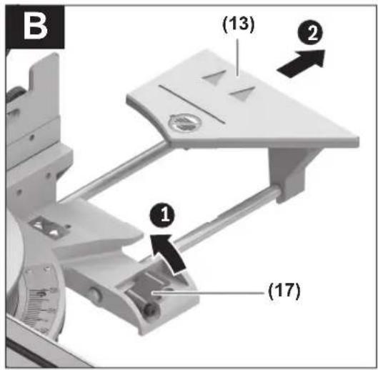
Extending the saw table (see figure B)
The free end of long workpieces must have something placed underneath it or be supported.
The saw table can be extended left and right using the saw table extensions (13).
– Pull the clamping lever (17) upwards.
– Pull out the saw table extension (13) to the required length.
- To lock the saw table extension, push the clamping lever (17) back down.
When sawing mitre/bevel angles, you have to pull the left-hand or right-hand adjustable fence (15) outwards depending on the cutting direction, or remove it completely.
| -2°-47°(left) | ≤ 44°(left) | - Loosen the locking screw (47).- Pull the left-hand adjustable fence (15) all the way out. |
| -2°-47°(left) | ≥ 45°(left) | - Loosen the locking screw (47).- Pull the left-hand adjustable fence (15) all the way out.- Lift the adjustable fence upwards and out of the way.- Remove the locking screw (47). |
| -2°-47°(left) | ≤ 44°(right) | - Loosen the locking screw (47).- Pull the right-hand adjustable fence (15) all the way out. |
| -2°-47°(left) | ≥ 45°(right) | - Loosen the locking screw (47).- Pull the right-hand adjustable fence (15) all the way out.- Lift the adjustable fence upwards and out of the way.- Remove the locking screw (47). |
Clamping the workpiece (see figure E)
To ensure maximum safety while working, the workpiece must always be firmly clamped.
Do not saw workpieces that are too small to clamp firmly.
- Press the workpiece firmly against the fence (14).
- Insert the supplied screw clamp (28) into one of the holes (34) intended for this purpose.
- Adjust the threaded rod (48) of the screw clamp to the workpiece height.
- Tighten the threaded rod (48) to fix the workpiece in place.
Adjusting mitre angles
To ensure precise cuts, the basic settings of the power tool must be checked and adjusted as necessary after intensive use (see "Checking and adjusting the basic settings", page 32).
Setting standard mitre angles (see figure F)
For quick and precise setting of commonly used mitre angles, detents (25) are provided on the saw table:
Leftward Rightward
0^
45^;31.6^;22.5^;15^15^;22.5^;31.6^;45^;60^
- Loosen the locking knob (21) if it is tightened.
- Pull the lever (22) and rotate the saw table (16) left or right to the required detent.
- Release the lever again. The lever must be felt to engage in the detent.
- Retighten the locking knob (21).
Setting any mitre angle (see figure G)
The mitre angle can be set between 52° (left side) and 60° (right side).
- Loosen the locking knob (21) if it is tightened.
- Pull the lever (22) and at the same time press the locking clamp (20) until this clicks into the slot provided for it. This means the saw table can now move freely.
- Turn the saw table (16) left or right by the locking knob until the angle indicator (24) shows the required mitre angle.
For mitre angles over 45°:
Pull the saw table extension (13) all the way out (see "Extending the saw table (see figure B)", page 30).
- Retighten the locking knob (21).
- To loosen the lever (22) again (for setting standard mitre angles), pull the lever upwards. The locking clamp (20) springs back into its original position and the lever (22) can click back into the detents (25).
Adjusting bevel angles
To ensure precise cuts, the basic settings of the power tool must be checked and adjusted as necessary after intensive use (see "Checking and adjusting the basic settings", page 32).
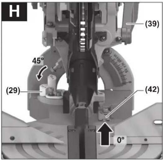
Setting standard bevel angles (see figure H)
For quick and precise setting of frequently used bevel angles, stops have been provided for the angles 0°, 45°, 22.5° and 33.9°.
- Loosen the clamping lever (39).
- Adjust the stops (29) or (42) as follows:
| Bevel angle | Stop Setting | |
| 0° | (42) | Slide the stop all the way back |
| 45° | (29) | Turn the stop all the way to the front |
| 22.5° | (29) | Turn the stop to the centre |
| 33.9° | (29) | Turn the stop to the back |
- Swivel the tool arm by the handle (9) into the required position.
- Retighten the clamping lever (39).
Setting any bevel angle
The bevel angle can be set between -2^ and +47^ .
- Loosen the clamping lever (39).
- Turn the stop (29) all the way to the back and pull the stop (42) all the way to the front. The full swivel range is now available.
- Swivel the tool arm left or right by the handle (9) until the angle indicator (41) shows the required bevel angle.
- Hold the tool arm in this position and retighten the clamping lever (39).
Start-up
Pay attention to the mains voltage. The voltage of the power source must match the voltage specified on the rating plate of the power tool. Power tools marked with 230 V can also be operated with 220 V.
▶ Products that are only sold in AUS and NZ: Use a residual current device (RCD) with a nominal residual current of 30 mA or less.
Switching on (see figure I)
- To start the power tool, first slide the lock-off switch (7) to the middle and then press and hold the on/off switch (8).
Note: For safety reasons, the on/off switch (8) cannot be locked; it must remain pressed during the entire operation.
Switching off
- To switch off, release the on/off switch (8).
Starting current limitation
The electronic starting current limitation feature restricts the power of the power tool when it is switched on and enables operation using a 16 A fuse.
Note: If the power tool runs at full speed immediately after being switched on, this means that the starting current limitation has failed. The power tool must be sent to the after-sales service immediately. For addresses, see (see "After-sales service and advice on using products", page 34).
Practical advice
General sawing instructions
▶ Always tighten the locking knob (21) and the clamping lever (39) firmly before sawing. Otherwise the saw blade can become wedged in the workpiece.
For all cuts, it must first be ensured that the saw blade at no time can come in contact with the fence, screw clamps or other machine parts. Remove any mounted auxiliary stops or adjust them accordingly.
Protect the saw blade against impact and shock. Do not subject the saw blade to lateral pressure.
Do not saw warped/bent workpieces. The workpiece must always have a straight edge to face against the fence. The free end of long and heavy workpieces must have something placed underneath it or be supported.
Make sure that the retracting blade guard operates properly and that it can move freely. The retracting blade guard must open when the tool arm is guided downward. When the tool arm is guided upward, the retracting blade guard must close again over the saw blade and lock in the uppermost position of the tool arm.
Marking the cutting line (see figure J)
A laser beam shows you the cutting line of the saw blade. This allows for exact positioning of the workpiece for sawing, without having to open the retracting blade guard.
- To activate this, turn on the laser beam using the switch (38).
- Align your mark on the workpiece with the right-hand edge of the laser line.
Note: Before sawing, check if the cutting line is still indicated correctly (see "Adjusting the laser", page 33). The laser beam can be misplaced due to vibrations from intensive use, for example.
Position of the operator (see figure K)
▶ Do not stand in line with the saw blade in front of the power tool. Always stand to the side of the saw blade. This protects your body against possible kickback.
- Keep hands, fingers and arms away from the rotating saw blade.
32 | English
- Do not reach one hand across the other when in front of the tool arm.
Permissible workpiece dimensions
Maximum workpiece dimensions:
Mitre angle Bevel angle Height x width [mm]
| 0° 0° 70 x 312 |
| 45° (right/left) 0° 70 x 225 |
| 0° 45° 45 x 312 |
| 45° (left) 45° 45 x 225 |
| 45° (right) 45° 45 x 225 |
Minimum workpiece dimensions (= all workpieces that can be secured left or right of the saw blade using the supplied screw clamps (28)): 100 x 40 mm (length x width)
Max. cutting depth (0°/0°): 70 mm
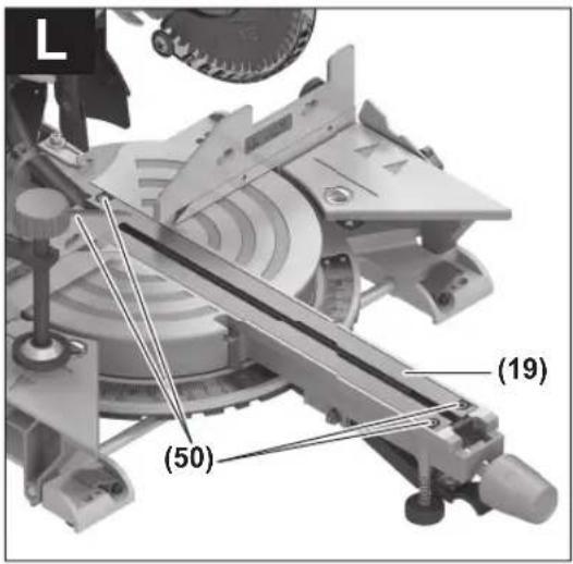
Replacing the insert plates (see figure L)
The red insert plates (19) can become worn after prolonged use of the power tool.
Replace defective insert plates.
- Bring the power tool into the work position.
- Loosen the screws (50) with a hex key (4 mm) and remove the old insert plates.
- Insert the new right-hand insert plate.
- Screw the insert plate as far as possible to the right with the screws (50) so that the saw blade does not come into contact with the insert plate over the entire length of the possible slide motion.
- Repeat the work steps in the same manner for the left-hand insert plate.
Sawing
▶ Always tighten the locking knob (21) and the clamping lever (39) firmly before sawing. Otherwise the saw blade can become wedged in the workpiece.
Sawing without slide movement (cutting off) (see figure M)
- For cuts without slide movement (small workpieces), loosen the locking screw (32) if it is tightened. Push the tool arm all the way towards the fence (14) and retighten the locking screw (32).
- Set the required mitre and/or bevel angle as necessary.
- Firmly clamp the workpiece as appropriate for its dimensions.
- Switch the power tool on.
- Slowly guide the tool arm downwards using the handle (9).
- Saw through the workpiece applying uniform feed.
- Switch off the power tool and wait until the saw blade has come to a complete stop.
- Slowly guide the tool arm upwards.
Sawing with slide movement
- For cuts made using the slide device (1) (wide workpieces), loosen the locking screw (32) if it is tightened.
- Set the required mitre and/or bevel angle as necessary.
- Firmly clamp the workpiece as appropriate for its dimensions.
- Pull the tool arm away from the fence (14) until the saw blade is in front of the workpiece.
- Switch the power tool on.
- Slowly guide the tool arm downwards using the handle (9).
- Now push the tool arm towards the fence (14) and saw through the workpiece with uniform feed.
- Switch off the power tool and wait until the saw blade has come to a complete stop.
- Slowly guide the tool arm upwards.
Sawing workpieces of the same length (see figure N)
The length stop (35) (accessory) can be used for easily sawing workpieces to the same length.
The length stop can be mounted on either side of the saw table extension (13).
- Loosen the locking screw (51) and move the length stop (35) over the clamping screw (52).
- Retighten the locking screw (51).
- Set the saw table extension (13) to the required length (see "Extending the saw table (see figure B)", page 30).
Adjusting the depth stop (sawing the groove) (see figure 0)
The depth stop needs to be adjusted if you wish to saw a groove.
- Swivel the depth stop (31) outwards.
- Swivel the tool arm by the handle (9) into the required position.
- Turn the adjusting screw (4) until the end of the screw touches the depth stop (31).
- Slowly guide the tool arm upwards.
Special workpieces
When sawing curved or round workpieces, these must be especially secured against slipping. At the cutting line, there should be no gap between the workpiece, fence and saw table.
If necessary, you will need to manufacture special fixtures.
Checking and adjusting the basic settings
▶ Pull the plug out of the socket before carrying out any work on the power tool.
To ensure precise cuts, the basic settings of the power tool must be checked and adjusted as necessary after intensive use.
Experience and suitable special tools are required for this.
A Bosch after-sales service point will handle this work quickly and reliably.
Adjusting the laser
Note: To test the laser function, the power tool must be connected to the power supply.
▶ While adjusting the laser (e.g. when moving the tool arm), never activate the on/off switch. Accidental starting of the power tool can lead to injuries.
- Bring the power tool into the work position.
- Turn the saw table (16) to the 0^ detent (25). The lever (22) must be felt to engage in the detent.
Checking (see figure P1)
- Draw a straight cutting line on the workpiece.
- Slowly guide the tool arm downwards using the handle (9).
- Align the workpiece in such a manner that the teeth of the saw blade are in alignment with the cutting line.
- Hold the workpiece in this position and slowly guide the tool arm upward.
- Clamp the workpiece.
- Turn on the laser beam using the switch (38).
The laser beam must be flush with the cutting line on the workpiece along its entire length, even if the tool arm is guided downwards.
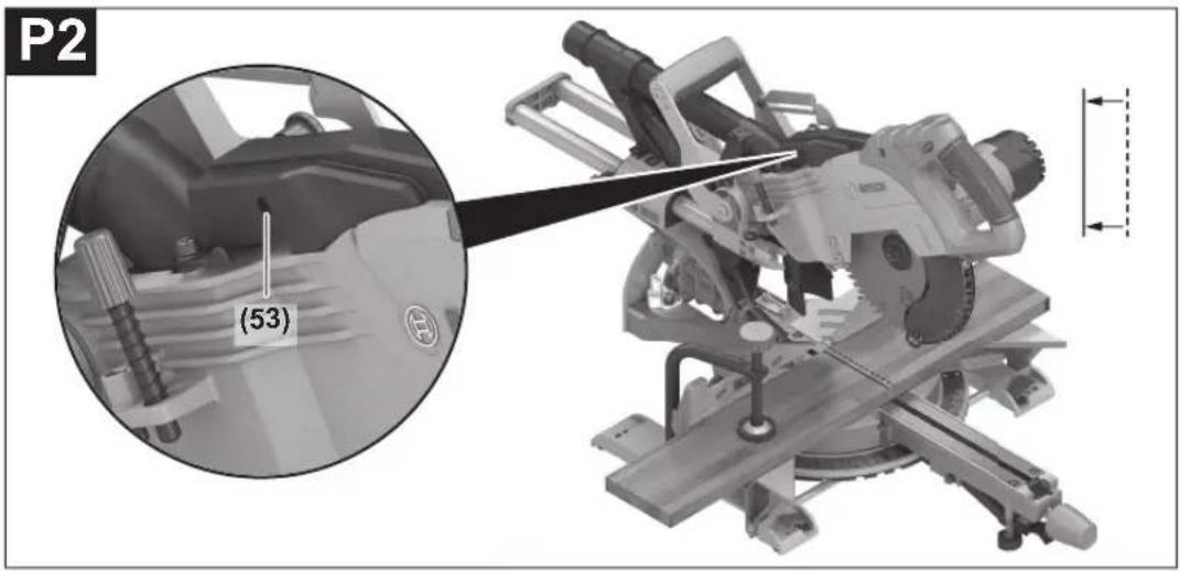
Setting (see figure P2)
- Turn the set screw (53) with a suitable screwdriver until the laser beam is parallel to the entire length of the cutting line on the workpiece.
One rotation anticlockwise moves the laser beam from left to right; one rotation clockwise moves the laser beam from right to left.
Setting the standard 0° bevel angle
- Bring the power tool into the work position.
- Turn the saw table (16) to the 0^ detent (25). The lever (22) must be felt to engage in the detent.
Checking (see figure Q1)
- Set an angle gauge to 90^ and place it on the saw table (16).
The leg of the angle gauge must be flush with the saw blade (12) along its entire length.
Setting (see figure Q2)
- Loosen the clamping lever (39).
- Slide the stop (42) all the way back.
- Loosen the lock nut of the stop screw (55) using a conventional ring spanner or open-ended spanner (10 mm).
- Turn the stop screw as far in or out as needed until the leg of the angle gauge is flush with the saw blade along its entire length.
- Retighten the clamping lever (39).
- Then retighten the lock nut of the stop screw (55).
If the angle indicator (41) is not aligned with the 0° mark on the scale (40) following adjustment, loosen the screw (54) using a conventional cross-headed screwdriver and align the angle indicator along the 0° mark.
Setting the standard 45° bevel angle
- Bring the power tool into the work position.
- Turn the saw table (16) to the 0^ detent (25). The lever (22) must be felt to engage in the detent.
- Turn the stop (29) all the way to the front.
- Loosen the clamping lever (39).
- Swivel the tool arm by the handle (9) to the left until the stop screw rests on the stop (29).
Checking (see figure R1)
- Set an angle gauge to 45^ and place it on the saw table (16).
The leg of the angle gauge must be flush with the saw blade (12) along its entire length.
Setting (see figure R2)
- Loosen the lock nut of the stop screw (56) using a conventional ring spanner or open-ended spanner (10 mm).
- Turn the stop screw as far in or out as needed until the leg of the angle gauge is flush with the saw blade along its entire length.
- Retighten the clamping lever (39).
- Then retighten the lock nut of the stop screw (56).
If the angle indicator (41) is not aligned with the 45^ mark on the scale (40) following adjustment, first check the 0^ setting for the bevel angle and the angle indicators once more. Then repeat the adjustment of the 45^ bevel angle.
Aligning the scale for mitre angles
- Bring the power tool into the work position.
- Turn the saw table (16) to the 0^ detent (25). The lever (22) must be felt to engage in the detent.
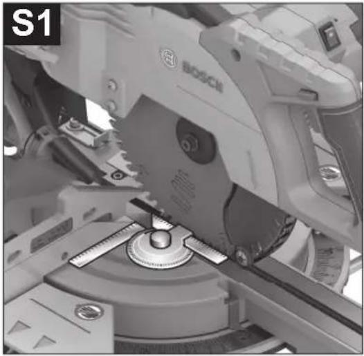
Checking (see figure S1)
- Set an angle gauge to 90^ and position it between the fence (14) and the saw blade (12) on the saw table (16).
The leg of the angle gauge must be flush with the saw blade (12) along its entire length.
Setting (see figure S2)
- Loosen all four set screws (58) with a cross-headed screwdriver and turn the saw table (16) together with the scale (18) until the leg of the angle gauge is flush with the saw blade along its entire length.
- Retighten the screws again.
If the angle indicator (24) is not aligned with the 0^ mark on the scale (18) following adjustment, loosen the screw (57) using a cross-headed screwdriver and align the angle indicator along the 0^ mark.
Transport (see figure T)
Before transporting the power tool, the following steps must be carried out:
- Loosen the locking screw (32) if it is tightened. Pull the tool arm fully forwards and retighten the locking screw.
- Make sure that the depth stop (31) is pressed all the way in and that the adjusting screw (4) fits through the recess without touching the depth stop when moving the tool arm.
- Bring the power tool into the transport position.
- Remove all accessories that cannot be securely fitted to the power tool.
34 | English
If possible, transport unused saw blades in an enclosed container.
- Wind up the mains cable and tie it together with the hook-and-loop strap (59).
- Carry the power tool by the transport handle (3) or hold it by the recessed handles (27) on the sides of the saw table.
▶ Only use the transport devices to transport the power tool and never the protective devices.
Maintenance and servicing
Maintenance and cleaning
▶ Pull the plug out of the socket before carrying out any work on the power tool.
▶ To ensure safe and efficient operation, always keep the power tool and the ventilation slots clean.
In order to avoid safety hazards, if the power supply cord needs to be replaced, this must be done by Bosch or by a customer service centre that is authorised to repair Bosch power tools.
The retracting blade guard must always be able to move freely and retract automatically. It is therefore important to keep the area around the retracting blade guard clean at all times.
Always remove dust and chips after working by blowing out with compressed air or using a brush.
Clean the guide roller (6) regularly.
To clean the laser unit, turn the laser cover (60) outwards and remove the dust with a paintbrush (see figure U).
Accessories
| Article number |
| Screw clamp 1 609 B04 224 |
| Insert plates 1 609 B03 717 |
| Dust bag 1 609 B05 010 |
| Length stop 1 609 B02 365 |
| Locking screw for length stop 1 609 B00 263 |
| Saw blades for wood and fibreboard, panels and strips |
| 216 x 30 mm saw blade, 48 teeth 2 608 640 641 |
| Saw blades for plastic and non-ferrous metals |
| 216 x 30 mm saw blade, 80 teeth 2 608 640 447 |
| 216 x 25.4 mm saw blade, 80 teeth 2 608 642 993 |
| Saw blades for all types of laminate flooring |
| 216 x 30 mm saw blade, 60 teeth 2 608 642 133 |
| 216 x 25.4 mm saw blade, 60 teeth 2 608 642 995 |
After-sales service and advice on using products
Our after-sales service responds to your questions concerning maintenance and repair of your product as well as spare parts. You can find explosion drawings and information on spare parts at: www.bosch-pt.com
The Bosch product use advice team will be happy to help you with any questions about our products and their accessories.
In all correspondence and spare parts orders, please always include the 10-digit article number given on the nameplate of the product.
Great Britain
Robert Bosch Ltd. (B.S.C.)
P.O. Box 98
Broadwater Park
North Orbital Road
Denham Uxbridge
UB 9 5HJ
At www.bosch-pt.co.uk you can order spare parts or arrange the collection of a product in need of servicing or repair.
Tel. Service: (0344) 7360109
E-Mail: boschservicecentre@bosch.com
Ireland
Origo Ltd.
Unit 23 Magna Drive
Magna Business Park
City West
Dublin 24
Tel. Service: (01) 4666700
Fax: (01) 4666888
Australia, New Zealand and Pacific Islands
Robert Bosch Australia Pty. Ltd.
Power Tools
Locked Bag 66
Clayton South VIC 3169
Customer Contact Center
Inside Australia:
Phone: (01300) 307044
Fax: (01300) 307045
Inside New Zealand:
Phone: (0800) 543353
Fax: (0800) 428570
Outside AU and NZ:
Phone: +61 3 95415555
www.bosch-pt.com.au
www.bosch-pt.co.nz
Republic of South Africa
Customer service
Hotline: (011) 6519600
Gauteng - BSC Service Centre
35 Roper Street, New Centre
Johannesburg
Tel.: (011) 4939375
Fax: (011) 4930126
E-mail: bsctools@icon.co.za
KZN - BSC Service Centre
Unit E, Almar Centre
143 Crompton Street
Pinetown
Tel.: (031) 7012120
Fax: (031) 7012446
E-mail: bsc.dur@za.bosch.com
Western Cape - BSC Service Centre
Democracy Way, Prosperity Park Milenerton
Tel.: (021) 5512577
Fax: (021) 5513223
E-mail: bsc@zsd.co.za
Bosch Headquarters
Midrand, Gauteng
Tel.: (011) 6519600
Fax: (011) 6519880
E-mail: rbsa-hq.pts@za.bosch.com
Disposal
The power tool, accessories and packaging should be recycled in an environmentally friendly manner.

Do not dispose of power tools along with household waste.
Only for EU countries:
According to the European Directive 2012/19/EU on Waste Electrical and Electronic Equipment and its implementation into national law, power tools that are no longer usable must be collected separately and disposed of in an environmentally friendly manner.
Français
(23) Pied anti-basculement
Transport (voir figure T)
natural_image
Simple line drawing of a door with padlock and open lock symbols, no text or labels presentPalanca de apriete cerrada:
Calle Robert Bosch No. 405
GCM 8 SJL GCM 8 SJL GCM 8 SJL GCM 8 SJL GCM 8 SJL
LASER BADATION O NOT EXPOSE USERS OF TELESCOPIC OPTICS ASS IN LASER PRODUCT
flowchart
graph TD
    A["Lock"] --> B["Up Arrow"]
    C["Unlock"] --> D["Down Arrow"]
Stationaire of flexibele montage
Kap-/geringssav GCM 8 SJL GCM 8 SJL GCM 8 SJL GCM 8 SJL GCM 8 SJL
| Savklingetykkelse mm 1,3-1,8 1,3-1,8 1,3-1,8 1,3-1,8 1,3-1,8 |
| maks. skære-bredde | mm 3,3 3,3 3,3 3,3 3,3 |
Boringsdiameter mm 30 30 25,4 25,4 25,4
Tilladte emnemål (se "Tilladte emnemål", Side 107)
Bosch Service Center
Telegrafvej 3
2750 Ballerup
På www.bosch-pt.dk kan der online bestilles reservedele eller oprettes en reparations ordre.
Tlf. Service Center: 44898855
Fax: 44898755
E-Mail: vaerktoej@dk.bosch.com
Bortskaffelse
Panelsåg GCM 8 SJL GCM 8 SJL GCM 8 SJL GCM 8 SJL GCM 8 SJL
Panelsåg GCM 8 SJL GCM 8 SJL GCM 8 SJL GCM 8 SJL GCM 8 SJL
| Klingansstomtjocklek | mm 1,3-1,8 1,3-1,8 1,3-1,8 1,3-1,8 1,3-1,8 |
| max. skärbredd mm 3,3 3,3 3,3 3,3 3,3 | |
| Centrumhåletsdiameter | mm 30 30 25,4 25,4 25,4 |
Bosch Service Center
Telegrafvej 3
2750 Ballerup
Danmark
Tel.: (08) 7501820 (inom Sverige)
Fax: (011) 187691
Avfallshantering
(26) Boringer for montering
(27) Grep-fordypninger
(28) Skrutvinge
(34) Boringer for skrutvinge
GCM 8 SJL GCM 8 SJL GCM 8 SJL GCM 8 SJL GCM 8 SJL
Sagbladdiameter mm 216 216 216 216 216
Stambladtykkelse mm 1,3-1,8 1,3-1,8 1,3-1,8 1,3-1,8 1,3-1,8
flowchart
graph TD
    A["Lock"] --> B["Up Arrow"]
    C["Unlock"] --> D["Down Arrow"]
natural_image
Simple line drawing of a door with padlock and open lock symbols, no text or labels presentRobert Bosch Sp. z o.o.
natural_image
Simple line drawing of a door with padlock and open lock symbols, no text or labels presentBosch Service Center PT
K Vápence 1621/16
692 01 Mikulov
flowchart
graph TD
    A["Lock"] --> B["Up Arrow"]
    C["Unlock"] --> D["Down Arrow"]
Pila na obklady GCM 8 SJL GCM 8 SJL GCM 8 SJL GCM 8 SJL GCM 8 SJL
Lapfúrész GCM 8 SJL GCM 8 SJL GCM 8 SJL GCM 8 SJL GCM 8 SJL
natural_image
Simple line drawing of a padlock icon with upward and downward arrows, no text or symbols presentflowchart
graph TD
    A["Lock"] --> B["Up Arrow"]
    C["Unlock"] --> D["Down Arrow"]
GCM 8 SJL GCM 8 SJL GCM 8 SJL GCM 8 SJL GCM 8 SJL
circular staționar
cu sanie de
glisare
Diametrul
mm 30 30 25,4 25,4 25,4
orificiului de
prindere
Service scule electrice
Strada Horia Măcelariu Nr. 30-34, sector 1
013937 Bucureşti
Service scule electrice
Strada Horia Măcelariu Nr. 30-34, sector 1
013937 Bucureşti, România
www.bosch-pt.com/bg/bg/
Бракуване
flowchart
graph TD
    A["Lock"] --> B["Up Arrow"]
    C["Unlock"] --> D["Down Arrow"]
IEC 80825 1-2014 *10.39mW, 650 nm LASERRADIATION O NOT EXPOSE USERS OF TELESCOPIC OPTICS CLASS IN LASER PRODUCT
Lasersko zračenje Ne posmatrajte direktno pomoću optike teleskopa laser klasa 1M

Rukama ne dopirite u područje testere, dok električni alat radi. Pri kontaktu sa listom testere postoji opasnost od povreda.

Nosite zaštitnu masku za prašinu.

Nosite zaštitne naočare.

Nosite zaštitu za sluh. Uticaj buke može da dovede do gubitka sluha.

Potezna żaga GCM 8 SJL GCM 8 SJL GCM 8 SJL GCM 8 SJL GCM 8 SJL
| mW < 0,39 < 0,39 < 0,39 < 0,39 < 0,39 | |||||
| Laserski razred 1M 1M 1M 1M | |||||
| Odstopanje laserske linije | mrad (polni kot) | 1,0 1,0 1,0 1,0 1,0 | |||
| Teža po EPTA-Procedure 01:2014 | kg 17,3 17,3 17,3 17,3 17,3 | ||||
| Razred zaščite pred el. udarom | ☐/II /II /II /II /☐ | ☐ | ☐ | ||
| Mere ustreznih žaginih listov | |||||
| Premer žaginega lista | mm 216 216 216 216 216 | ||||
| Debelina osnovnega žaginega lista | mm 1,3-1,8 1,3-1,8 1,3-1,8 1,3-1,8 1,3-1,8 | ||||
| Maks. širina reza mm 3,3 3,3 3,3 3,3 | |||||
| Premer izvrtine mm 30 30 25,4 25,4 25,4 | |||||
natural_image
Simple line drawing of a door with padlock and open lock symbols, no text or labels presentnatural_image
Simple line drawing of a shield with four padlock icons and directional arrows (no text or symbols)Kinnitushoob on suletud:
Järkamissaag GCM 8 SJL GCM 8 SJL GCM 8 SJL GCM 8 SJL GCM 8 SJL
| Tootenumber | 3 601 M19 161 | 3 601 M19 1.. | 3 601 M19 1C1 | 3 601 M19 181 | 3 601 M19 141 | |
| 3 601 M19 1B1 | ||||||
| 3 601 M19 1K1 | ||||||
| Nimivõimsus W 1250 1600 1250 1400 1600 | ||||||
| Tühikäigu-põörlemiskiirus | min^1 | 5600 | 5600 | 5600 | 5600 | |
| Käivitusvoolu piiraja | ●●●●● | |||||
| Laseri tüüp nm 650 650 650 650 650 | ||||||
| mW < 0,39 < 0,39 < 0,39 < 0,39 < 0,39 | ||||||
| Laseri klass 1M 1M 1M 1M 1M | ||||||
| Laserkiire hajumine | mrad (täisring ) | 1,0 | 1,0 | 1,0 | 1,0 | |
| Kaal vastavalt EPTA-Procedure 01:2014-le | kg 17,3 | 17,3 | 17,3 | 17,3 | 17,3 | |
| Kaitseklass | ☐/II | ☐/II | ☐/II | ☐/II | ||
| Sobivate saeketaste mõõtmed | ||||||
| Saeketta läbimõõt | mm | 216 | 216 | 216 | 216 | |
| Saeketta paksus | mm | 1,3-1,8 | 1,3-1,8 | 1,3-1,8 | 1,3-1,8 | |
| max lõikelaius | mm | 3,3 | 3,3 | 3,3 | 3,3 | |
| Saeketta siseava läbimõõt | mm | 30 | 30 | 25,4 | 25,4 | |
| IEC 80825 1:2014<0.39mW, ≤50 mm |
| LASER RADIATIONDO NOT EXPOSE USERS OFTELESCOPIC OPTICSCLASS IN LASER PRODUCT |

Lāzera starojums
flowchart
graph TD
    A["Lock"] --> B["Up"]
    C["Unlock"] --> D["Down"]
flowchart
graph TD
    A["Lock"] --> B["Up Arrow"]
    C["Unlock"] --> D["Down Arrow"]
natural_image
Simple line drawing of a door with padlock and open lock symbols, no text or labels present夾緊桿閉合:
固定住已調整好垂直斜鋸角的機臂。
夾緊桿開啟:
可讓您調整垂直斜鋸角。
產品和規格

flowchart
graph TD
    A["Lock"] --> B["Up Arrow"]
    C["Unlock"] --> D["Down Arrow"]
고정레버 닫힘:
▶ 000000000000000000000000000000000000000000000000000
□□ □□□□(□□ A □□)
▶ Economic and daily economic and financial and financial and financial and financial and financial and financial and financial and financial and financial and financial and financial and financial and financial and financial and financial and financial and financial and financial and financial and financial and financial and financial and financial and financial and financial and financial and financial and financial and financial and financial and financial and financial and financial and financial and financial and financial and financial and financial and financial and financial and financial and financial and financial and financial and financial and financial and financial and financial and financial and financial and finance, business, industry, education, education, healthcare, education, healthcare, education, healthcare, education, healthcare, education, healthcare, education, healthcare, education, healthcare, education, healthcare, education, healthcare, education, healthcare, education, healthcare, education, healthcare, education, healthcare, education, healthcare, education, healthcare, education, healthcare, education, healthcare, education, healthcare, education, healthcare, education, healthcare, education, healthcare, education, healthcare, education, healthcare, education, healthcare, education, healthcare, education, education, healthcare, education, education, healthcare, education, education, healthcare, education, education, healthcare, education, education, healthcare, education, education, healthcare, education, education, healthcare, education, education, healthcare, education, education, healthcare, education, education, healthcare, education, education, healthcare, education, education, healthcare, education, education, healthcare, education, education, healthcare, education, education, healthcare, education, education, healthcare, education, education, health
-손,손가락,팔을 회전하는 톱날 가까이에 두지 마십시오.
- 툴암앞에서 손을 교차시키지 마십시오.
작업물 허용 크기
최대 작업물 크기:
IEC 60825-1-2014 <0.33mW, 050 nm LASER RADIATION O NOT EXPOSED USERS OF TELESCOPIC OPTICS ASS IN LASER PRODUCT
-ขอแนะนา provides most famous national government's policies for P2
IEC 60025-1-2014 +0.39mW, 650 nm LASER RADIATION O NOT EXPOSE USERS OF TELESCOPIC OPTICS ASS IN LASER PRODUCT
natural_image
Simple line drawing of a door with four padlock icons and directional arrows (no text or symbols)Palma Tower 10th Floor
Jalan RA Kartini II-S Kaveling 6
Pondok Pinang, Kebayoran Lama
flowchart
graph TD
    A["Lock"] --> B["Upward Arrow"]
    C["Unlock"] --> D["Downward Arrow"]
Cân kép đóng:
Đơn nguyên 8BC, GT Tower, Tầng 08,
Đường 169, Tiếp Khắc Blvd, Sangkat Veal Vong, Khan 7 Makara, Phnom Penh
VAT TIN: 100 169 511
Tel.: +855 23 900 685
Tel.: +855 23 900 660
www.bosch.com.kh
Sự thải bổ
ال,’م,”م,”م,”م,”م,”م,”م,”م,”م,”م,”م,”م,”م,”م,”م,”م,”م,”م,”م,”م,”م,”م,”م,”م,”م,”م,”م,”م,”م,”م,”م,”م,”م,”م,”م,”م,”م,”م,”م,”م,”م,”م,”م,”م,”م,”م,”م,”م,”م,”م,”م”
flowchart
graph TD
    A["Lock"] --> B["Up Arrow"]
    C["Unlock"] --> D["Down Arrow"]
وصف المنتج والأداء
WOAO MOO NCSL MUNSHAR MRKB
- الملزمة 28(
+216 71 427 496/879: م forecasts
+216 71 428 621 : فاكس
flowchart
graph TD
    A["Lock"] --> B["Up Arrow"]
    C["Unlock"] --> D["Down Arrow"]