Combi Care 38 E - Lawn mower AL-KO - Free user manual and instructions
Find the device manual for free Combi Care 38 E AL-KO in PDF.
| Brand | AL-KO |
| Model | Combi Care 38 E |
| Product type | Lawn mower (scarifier/aerator) |
| Working width | 38 cm |
| Power supply | 230 V / 50 Hz, 10 A |
| Motor power | 1300 W (estimated) |
| Weight | 11 kg (estimated) |
| Dimensions (L x W x H) | 70 x 45 x 35 cm (estimated) |
| Working depth | 5 positions (1-5) |
| Cutting type | Scarifying and aerating with rotating knives |
| Collection bag | Yes, integrated |
| Safety devices | Motor circuit breaker, safety switch, rear flap, visual locking indicator |
| Power cable | H05RN-F 3 x 1.5 mm², sufficient length |
| Protection | 30 mA residual current device recommended |
| Sound level | ~85 dB(A) (estimated) |
| Maintenance | Cleaning after each use, replacement of knives |
| Wear parts | Knives, steel tines of the aerator roller |
| Warranty | Legal warranty against manufacturing defects, wear parts excluded |
| Use | Private lawns, domestic use only |
| Included accessories | Collection bag, user manual |
Frequently Asked Questions - Combi Care 38 E AL-KO
User questions about Combi Care 38 E AL-KO
0 question about this device. Answer the ones you know or ask your own.
Ask a new question about this device
Download the instructions for your Lawn mower in PDF format for free! Find your manual Combi Care 38 E - AL-KO and take your electronic device back in hand. On this page are published all the documents necessary for the use of your device. Combi Care 38 E by AL-KO.
USER MANUAL Combi Care 38 E AL-KO
natural_image
Line drawing of a lawn mower with handlebars and wheels (no text or symbols)


DE
GB
NL
FR
ES
PT
IT
SI
HR
RS
PL
CZ
SK
HU
DK
SE
NO
FI
EE
LV
LT
RU
UA
BG
RO
GR
MK
TR
GB: Translation of the original instructions for use ....14
AL-KO KOBER GROUP Kötz, Germany
This documentation or excerpts therefrom may not be reproduced or disclosed to third parties without the express permission of the AL-KO KOBER GROUP.

text_image
01 5 4a 2x Ø4x25 6 3a 4b 6b 3b 4 ① 1a 1b min. 200 mm ② 2a 2b Ø5x30 2c 2d 02 ⑦ 8 9 ⑩ 11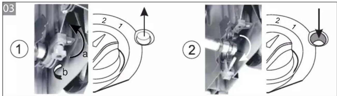
text_image
03 ① a b 2 1 ② 2 1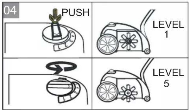
text_image
04 PUSH LEVEL 1 LEVEL 5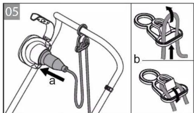
text_image
05 a b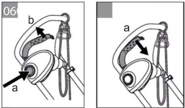
text_image
06 b a a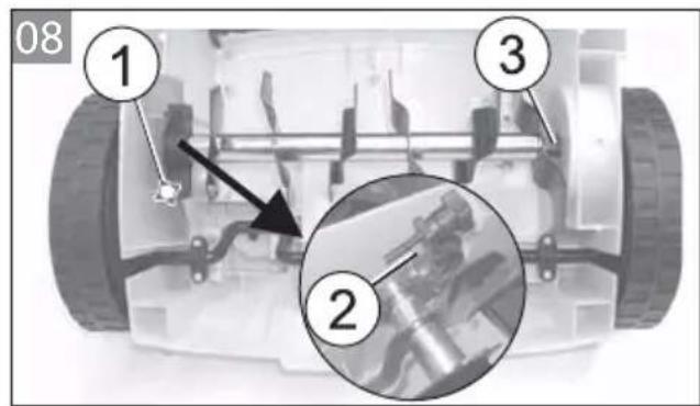
text_image
08 1 2 3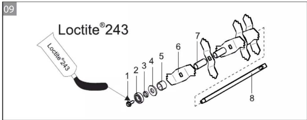
text_image
09 Loctite®243 Loctite®243 1 2 3 4 5 6 7 8| CC 38 E | |||
| 112800 | |||
 | 1060 x 550 x 1093 mm 1,3 kW |  | |
 | ca. 14,0 kg |  | 4000 min-1 |
 | 5 x |  | LPA=86 dB (A)K=3,0 dB (A) |
 |  380 mm 380 mm |  | avhw=8 m/s2K=1,5 m/s2ISO 20643 |
 |  370 mm 370 mm |  | LWA=99 dB (A) |
 | 230 V ca. 55 l |  | |
 | min. 10 A | ||
Einleitung
text_image
Labeled diagram of a lawn mower with numbered parts for identification- Please read this document before putting the machine into operation. This is essential for safe working and trouble-free handling.
■ Comply with the safety and warning instructions this documentation and on the machine.
This document is a permanent component of the described product, and should remain with the machine if it is sold to someone else.
Explanation of symbols

Important!
Following these warning instructions can help to avoid personal injury and/or damage to property.

Special instructions for ease of understanding and handling.
Table of contents
Introduction....14
Product description 14
Safety instructions 16
Assembly 16
Start-up....16
Power cable safety 17
Maintenance and care 18
Help in case of malfunction 19
Disposal....19
Guarantee....19
Product description
Intended use
This machine is intended for loosening and aerating a lawn (scarifying) in private applications, and is only allowed to be used on dried lawns which have been mown short.
Any use not in accordance with this designated use shall be regarded as misuse.

Important!
The machine is not allowed to be used in commercial applications.
Safety and protective devices
Motor protection switch
The motor protection switch switches off the scarifi er/ aerator if the motor is overloaded. Do not deactivate the function of the motor protection switch.
Proceed as follows if the motor protection switch has switched off the machine:
- Disconnect the machine from the mains.
- Determine the cause of the overload.
- After allowing the machine to cool down for 2 to 3 minutes, reconnect the power cable and start operating the machine.
Operator presence control
The machine is equipped with an operator presence control which stops the machine when it is released.

Danger!
Do not deactivate the function of the operator presence control.
Rear fl ap
The machine is equipped with a rear fl ap.
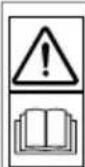
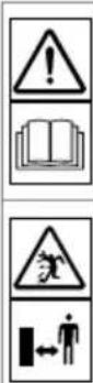
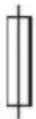
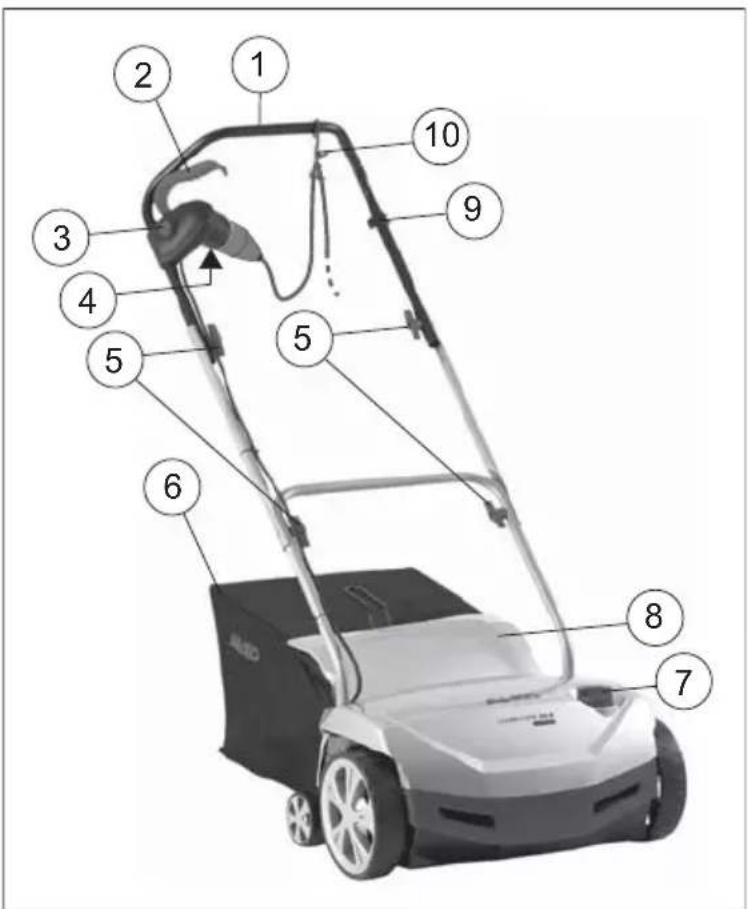
Visual safety indicator (03, 08)
The visual safety indicator displays when the blade shaft is secured.
The work shaft is secured correctly when the green mark is visible (5 mm) (1).
If the green mark is not visible any more and a red mark is visible (2),
the securing of the blade shaft is loose. The securing of the blade shaft has to be checked and bolted (08/1, 08/3).
Product overview
text_image
Labeled diagram of a lawn mower with numbered parts for identification| 1 | Handlebar |
| 2 | Operator presence control |
| 3 | Safety pushbutton switch |
| 4 | Plug on the safety pushbutton switch |
| 5 | Turning handles for folding back the handlebar |
| 6 | Grass catcher |
| 7 | Rotary switch for setting the working depth |
| 8 | Baffl e |
| 9 | Terminal block for cable strain relief |
| 10 | Cable strain relief |
Symbols on the appliance
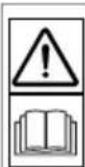
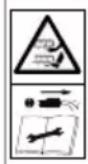
Read the operating instructions before starting operation.
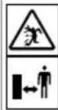
Keep other people out of the danger area. Maintain a safety distance.
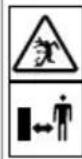
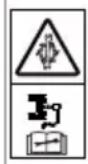
 | Disconnect the mains plug before starting maintenance work on the blade system! |
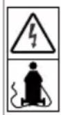 | Do not run over the mains cable. Danger of electric shock if the mains cable is damaged! |
 | Keep your hands and feet away from the blade system. Disconnect the appliance from the mains supply before maintenance and care as well as cleaning work! |
 | Remove the spark plug before starting maintenance work on the blade system! |
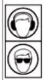 | Wear hearing and eye protection! |
Safety instructions
■ Only use the machine if it is in perfect technical condition
■ Protect the machine against moisture
■ Do not deactivate safety and protective devices
■ Wear protective glasses and ear defenders
■ Wear long trousers and sturdy shoes
- Keep your hands and feet away from the blade system
- Do not place your hands and feet close to any rotating parts
- Keep third parties away from the danger area
■ Remove foreign bodies from the working area
■ When leaving the machine:
■ Switching off the motor
- Wait for the blade system to come to a stop
■ Disconnect from the mains
■ Do not leave the machine unsupervised
Children, or other people who are not familiar with the operating instructions, are not allowed to use the machine
The machine must not be operated by persons under the influence of alcohol, drugs or medication
■ Comply with the local regulations on minimum age of people operating the machine
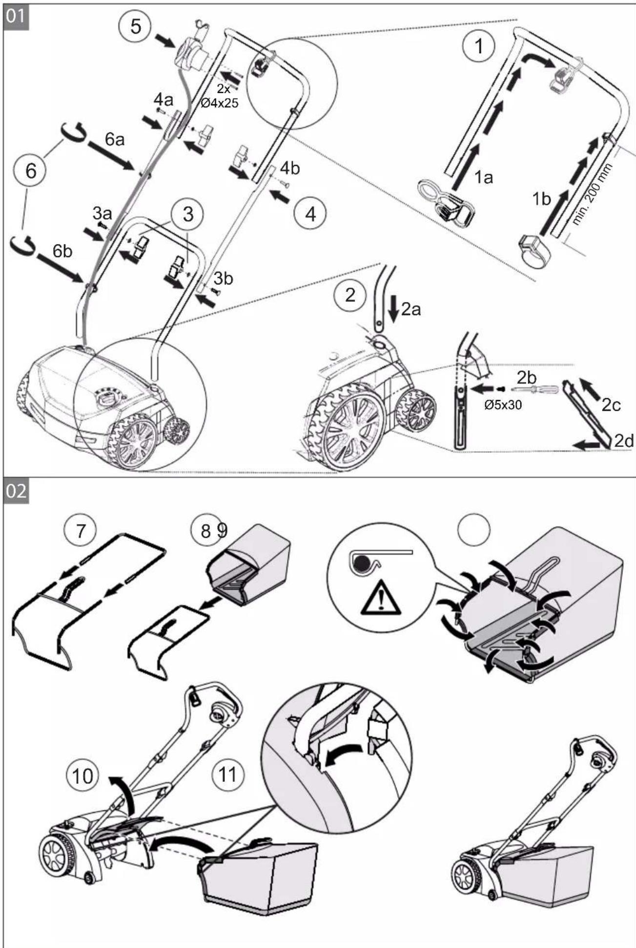
Assembly
Assemble the machine in accordance with the illustrations (01, 02).
! Important!
The appliance is not allowed to be operated unless it has been fully assembled.
Start-up
! Important!
Always perform a visual check prior to start-up. Do not operate the machine if the blade system and/or the fastening parts are loose, damaged or worn.
■ Heed the country-specific regulations for the operating times of chain saws
■ Always comply with the operating instructions supplied from the engine manufacturer
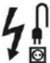
Power cable safety
■ Only use rubber-sheathed cables with quality H05RN-F acc. to DIN/VDE 0282 with a conductor cross section of 3 phases of 1.5 mm² each.
The type designation must be marked on the power cable. The plug and coupling socket must be made from rubber or sheathed in rubber, and be in accordance with DIN/VDE 0620.
■ Only use a power cable with sufficient length.
■ The power cable, plug and coupling socket must be protected against splash water.
■ Repairs on the power cable, plug and coupling socket are only allowed to be carried out by authorised specialist companies. A defective power cable (e.g. with cracks, cuts, crushed or kinked points in the insulation) is not allowed to be used.
■ Protect the plug connections against moisture.

Danger!
Do not damage or cut the power cable.
If the power cable is damaged, immediately disconnect it from the mains.
Electrical requirements
■ 230 V/50 Hz alternating current
■ Minimum cross section
■ Power cable = 1.5 mm ^4
■ Minimum fusing of mains connection = 10 A
■ Residual-current circuit breaker (RCCB)
■ Maximum tripping current = 30 mA.
Establishing the mains connection (05)
- Connect the coupling part of the power cable to the plug on the safety pushbutton switch (a).
- Coil the power cable into a loop and hook it into the cable strain relief (b). Leave the loop long enough for the cable strain relief to be able to slide from one side to the other.

Danger!
Never operate the machine from mains sockets which do not have a residual-current circuit breaker.
Setting the working depth (04)

Important!
Only set the working depth if the engine is switched off and the blade shaft is stopped.
Set the working depth of the blade shaft at the dial selector.
- Tilt the scarifi er backwards with the handlebar.
- Push the twist switch down and turn it to level "1".
Positions on the dial selector:
1 - 5 = Setting the working depth (04)

With new blades, set the dial selector to position 2 at most!
The correct working depth depends on:
■ the condition of the lawn
■ the wear on the blades
If the working depth is set too low:
■ the scarifi er will stop
■ the engine will stall
In this case, move the dial selector back to a shallower working depth.

Always mow the lawn before scarifying.
Starting the engine (06)
- Push and hold the button of the safety pushbutton switch (a).
- Pull the operator presence control against the handlebar (b). The motor starts.

The operator presence control does not lock in place. It must be held in place all the time.
- Release the button of the safety pushbutton switch.
Switching off the motor (07)
- Release the operator presence control (a). It automatically returns to its initial position. The motor is switched off.

Danger of lacerations!
The blade shaft keeps turning under its own momentum! After switching off, do not reach under the machine straight away.
Hooking in/unhooking the grass catcher
- Switch off the engine before hooking in/unhooking the grass catcher.
- Wait for the blade shaft to come to a stop
General notes on operation
The blade system must be able to turn entirely freely in order for the machine to be started
- Keep the power cable out of the working area
■ Only control the machine using the handlebar. This ensures the necessary safety clearance.
■ Be particularly careful when turning the scarifier or pulling the machine behind you
■ Make sure you can stand securely on slopes
■ Always scarify across the slope
■ Never scarify on steep slopes
■ Always scarify at walking pace
■ Never tilt or transport the machine when the engine is running
■ Have the machine checked by a specialist if the following events occur:
■ After running into an obstacle
■ if the engine stops suddenly
If a blade is bent
If the blade shaft is bent
If the V-belt is defective
Maintenance and care

Danger!
Risk of injury on the blade shaft.
Wear protective gloves!

Do not open the engine housing. Maintenance of the engine must be done by an authorised specialist workshop.
■ Disconnect the mains plug before any maintenance and cleaning work! Wait for the shaft to come to a stop.
■ Only use genuine spare parts.
■ Only renew worn or damaged implements and pins as a set, in order to avoid imbalances.
■ Do not spray the equipment with water!
Water ingress can cause irreparable damage to the motor and the safety pushbutton switch.
■ Clean the machine after each use (scraper, cloth, etc.).
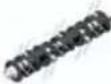
Remove the blade shaft (08).
- Unscrew and remove the screw (1) of the bearing.
- Fold up the bearing half (2).
- Lift the blade shaft out of the lower bearing half and pull it out of the drive side (3).
Install in reverse order.
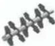
Remove the blades (09).

Before removing the blades, check their installation position!
- Unscrew and remove hexagon bolt (1).
- Carefully pull the ball bearing (2) off the shaft (8).
- Pull the thrust ring (3), washer (4) and short spacer tube (5) off the shaft.
- Pull off the blades (6) and long spacer tubes one after another.
Install in reverse order.
Removing the aerator roller
Remove the aerator roller and renew the steel spring tines in the same way as the blade shaft.
Help in case of malfunction
| Malfunction Help | |
| Motor does not start | Check the power cable and the residual-current circuit breakerPush the operator presence control towards the top handlebar.Select a lower working depth |
| Shaft does not rotate | Select a lower working depthClear the bladesContact a customer service workshop |
| The engine loses power | Select a lower working depthRenew worn blades.Clean the housingMow the lawn (grass is too long). |
| Poor scarifying performance | Select a lower working depthRenew worn blades. |
| Malfunction Help | |
| Machine is not running smoothlyMachine is vibrating | ■ Damaged blades.■ Contact a customer service workshop. |
Malfunctions that cannot be rectified using this table must be attended to by an authorised specialist workshop.
Disposal

Do not dispose of worn-out equipment, spent batteries or rechargeable batteries in domestic waste.
Packaging, equipment and accessories are made from recyclable materials, and must be disposed of accordingly.
Guarantee
We will resolve any material or manufacturing faults on the machine during the legal warranty period for claims relating to faults, in accordance with our choice either to repair or replace. The legal warranty period is determined by the legislation of the country in which the appliance was purchased.
Our warranty promise applies only if: The warranty becomes void in the case of:
■ the machine has been handled correctly
■ the instructions for use have been complied with
■ original spare parts have been used
■ someone has attempted to repair the machine
■ any technical modifications have been made to the machine
■ the machine has not been used correctly (e.g. commercial or communal use)
The guarantee excludes:
- Paint damage that can be attributed to normal wear and tear
■ Wear parts that are marked with xxx xxx frame on the spare parts card
- Internal combustion engines – These are covered by the separate warranty provisions of the corresponding engine manufacturers
In the event of a warranty claim, please take this warranty declaration and your proof of purchase and contact your dealer or the nearest authorised customer service centre. This warranty promise does not affect your statutory rights.
Inleiding
text_image
Labeled diagram of a lawn mower with numbered parts for identificationtext_image
Labeled diagram of a lawn mower with numbered parts for identificationtext_image
Labeled diagram of a lawn mower with numbered parts for identificationtext_image
Labeled diagram of a lawn mower with numbered parts for identificationtext_image
Labeled diagram of a lawn mower with numbered parts for identificationtext_image
Labeled diagram of a lawn mower with numbered parts for identificationtext_image
Labeled diagram of a lawn mower with numbered parts for identification| 1 | Ručka za upravljanje |
| 2 | Sigurnosna ručica |
| 3 | Sigurnosna sklopka s tipkom |
| 4 | Utikač na sigurnosnoj sklopci s tipkom |
| 5 | Okrene ručke za zaklapanje ručke za upravljanje |
| 6 | Košara za sakupljanje trave |
| 7 | Okretna sklopka za namještanje radne dubine |
| 8 | Zaštitna zaklopka |
| 9 | Sigurnosna stezaljka za otpuštanje kabela |
| 10 | Rasterećenje povlačenja kabela |
Simboli na uređaju