
GTA 60 W Professional - Service après-vente BOSCH - Free user manual and instructions
Find the device manual for free GTA 60 W Professional BOSCH in PDF.

| Product type | Work table for stationary saw |
| Brand | Bosch |
| Model | GTA 60 W Professional |
| Article number | 3 601 M12 000 |
| Table height | 622 mm |
| Maximum load capacity | 180 kg (power tool + workpiece) |
| Weight | 35 kg |
| Tire pressure | 1.7–2 bar (max. 2.5 bar) |
| Main materials | Metal and plastic |
| Included accessories | Mounting plate, upper and lower frame, wheels with crossbars, foot support, mounting set (bolts, washers, nuts) |
| Required tools not included | Phillips screwdriver, open-end wrench (10 mm, 8 mm, 6 mm) |
| Intended use | Integration of Bosch stationary saws (e.g., GTS 10) and other brands via universal mounting plate |
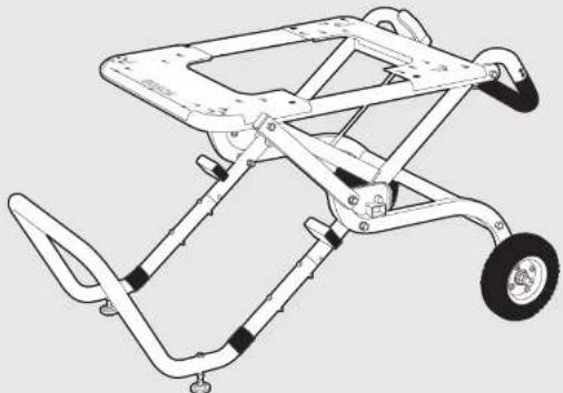
| Main functions | Stable support for stationary saw, easy transport thanks to wheels and folding mechanism, height adjustment of feet for leveling |
| Safety | Wheel lock, locking bolts, adjustable feet, do not overload, do not use as ladder |
| Maintenance and cleaning | Clean regularly, repair by authorized Bosch after-sales service |
| Spare parts and repairability | Spare parts available, exploded view on www.bosch-pt.com, Bosch after-sales service |
| General information | Manual available in multiple languages, translation available on request |
Frequently Asked Questions - GTA 60 W Professional BOSCH
User questions about GTA 60 W Professional BOSCH
0 question about this device. Answer the ones you know or ask your own.
Ask a new question about this device
Download the instructions for your Service après-vente in PDF format for free! Find your manual GTA 60 W Professional - BOSCH and take your electronic device back in hand. On this page are published all the documents necessary for the use of your device. GTA 60 W Professional by BOSCH.
USER MANUAL GTA 60 W Professional BOSCH
OBJ BUCH-857-003 book Page 1 Thursday, January 29, 2009 10:22 AM
natural_image
Line drawing of a mobile phone tower with wheels and handle (no text or symbols)Robert Bosch GmbH
Power Tools Division
70745 Leinfelden-Echterdingen
Germany
www.bosch-pt.com
1 609 929 S18 (2009.02) P5 / 136 UNI
GTA 60 W Professional

BOSCH
natural_image
Line drawing of a chair with handle and seat, labeled with number 6 (no text or symbols on the diagram itself)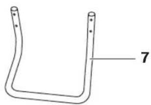
natural_image
Simple line drawing of a bent U-shaped object with no text or symbols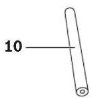
natural_image
Technical line drawing of two bolted components with no text or symbols6x M10 x 100
2x M10 x 50
4x M6 x 110
4x M6 x 75
4× M6 × 40

2x M10

18x M10
8x M6
6x M10
6x M8
4x M6
Bosch Power Tools 1 609 929 S18 | (29/1/09)
6
E
M10M10 M10 x 100
F
Bosch Power Tools 1 609 929 S18 | (29/1/09)
8 | Deutsch
Sicherheitshinweise
| Hersteller Modell | Montage-bohrung | |
| Bosch | GTS 10 B | |
| DeWALT | DW744XP D | |
| Metabo | TS 250 Me | |
| Makita | 2703 M | |
| Hitachi | C 10 RA 2 H | |
General Safety Rules
WARNING Read all warning notes and instructions enc closed with the
saw stand and the power tool to be mounted. Failure to follow the warnings and instructions may result in electric shock, fire and/or serious injury.
Safety Warnings for Saw Stands
▶ Pull the plug from the mains receptacle and/or remove the battery from the power tool before making adjustments on the tool or changing tool accessories. Unintentional switching on of the power tool is the cause of many accidents.
▶ Assemble the saw stand in the proper manner before mounting the power tool. Proper assembly is important to prevent the risk of a collapse of the saw stand.
▶ Attach the power tool securely to the saw stand before using it. Slipping off of the power tool on the saw stand can lead to loss of control.
Place the saw stand on a firm, level and horizontal surface. If the saw stand can slip off or wobbles, the power tool or the workpiece cannot be uniformly and securely guided.
▶ Do not overload the saw stand and do not use it as a ladder or scaffolding. Overloading or standing on the saw stand can lead to the upward shifting of the centre of gravity of the stand and its tipping over.
When working or transporting, take care that all bolts and connecting elements are firmly tightened. Loose connections can lead to instability and inexact sawing.
Mount and dismount the power tool only when it is in the transport position (for instructions on the transport position, also see the operating instructions of the respective power tool). Otherwise, the power tool can have such an unfavourable centre of gravity that it cannot be held securely.
▶ When the power tool is mounted to the mounting plate, operate it exclusively on the saw stand. Without the saw stand, the mounting plate with the power tool does not stand securely and can tip over.
▶ Ensure that long and heavy workpieces do not affect the equilibrium of the saw stand. Long and/or heavy workpieces must be supported at the free end.
▶ Keep your fingers clear of the hinge points while pushing the saw stand together or pulling it apart. Danger of fingers being crushed or contused.
14 | English
Symbols
The following symbols can be important for the operation of your saw stand. Please memorise the symbols and their meanings. The correct interpretation of the symbols helps you operate the saw stand better and more secure.
Symbol Meaning
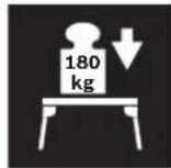
The maximum carrying capacity (power tool + workpiece) of the saw stand is 180 kg.
Functional Description

Read all warning notes and instructions enc closed with the saw stand and the power tool to be mounted. Failure to follow the warnings and instructions may result in electric shock, fire and/or serious injury.
Intended Use
The saw stand is intended exclusively for mounting the following stationary Bosch saws (as of 2008.11):
- GTS 10 3 601 L30 0..
Together with the power tool, the saw stand is intended for the cutting to length of boards and profiles.
The saw stand is also suitable for various competitor products (see page 16).
Product Features
The numbering of the product features refers to the illustration of the saw stand on the graphics pages.
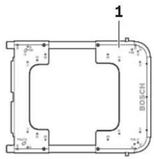
1 Mounting plate
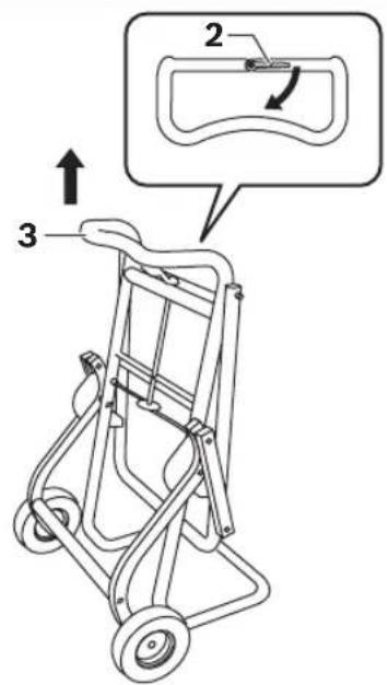
2 Lock for the wheels 8
3 Handle
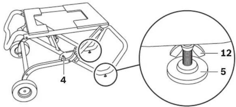
4 Limit bolt
5 Height-adjustable leg
6 Upper frame with lock 2
7 Bottom frame
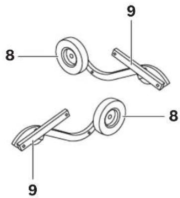
8 Wheel
9 Linkage bar
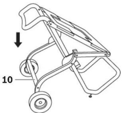
10 Foot lever
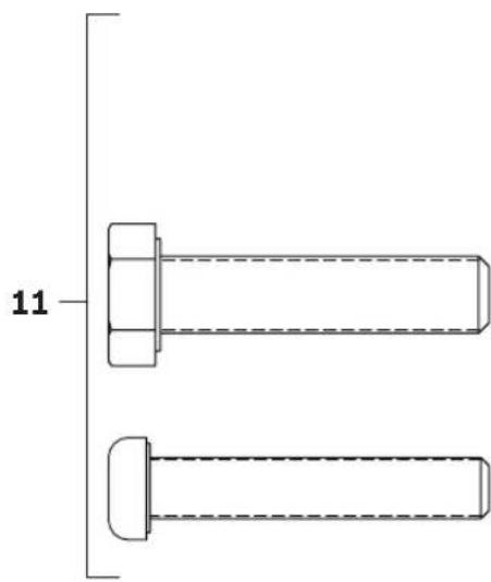
11 Fastening kit
12 Wing nut
*Accessories shown or described are not part of the standard delivery scope of the product. A complete overview of accessories can be found in our accessories program.
Technical Data
| Saw stand G T A 6 0 W | |
| Professional | |
| Article number | 3 601 M12 000 |
| Height of saw stand | mm 622 |
| Max. carrying capacity(power tool + work-piece) | kg 180 |
| Weight according to EPTA-Procedure01/2003 | kg 35 |
Assembly
Delivery Scope

Please also observe the representation of the delivery scope at the beginning of the operating instructions.
Before assembling the saw stand, check if all parts listed below are provided:
No. Designation Quantity
| 1 | Mounting plate 1 | |
| 6 | Upper frame with lock 2 1 | |
| 7 | Bottom frame 1 | |
| 8 | Wheel with linkage bar 9 2 | |
| 10 | Foot lever 1 | |
| 11 | Fastening kitconsisting of:- Hexagon boltM10 x 100 6M10 x 50 2M6 x 110 4M6 x 75 4M6 x 40 4- Phillips screwM8 x 50 6- WasherM10 18M10 (clamping washer) 2M6 8- Lock nutM10 6M8 6M6 4 |
Additionally required tools (not in delivery scope):
- Phillips screwdriver
- Open-end spanner (10 mm, 8 mm, 6 mm)
Assembling the Mobile Stand Base
- Carefully remove all parts included in the delivery from their packaging.
- Remove all packaging material.
- For assembly, follow figures A - E. Also observe the following notes.
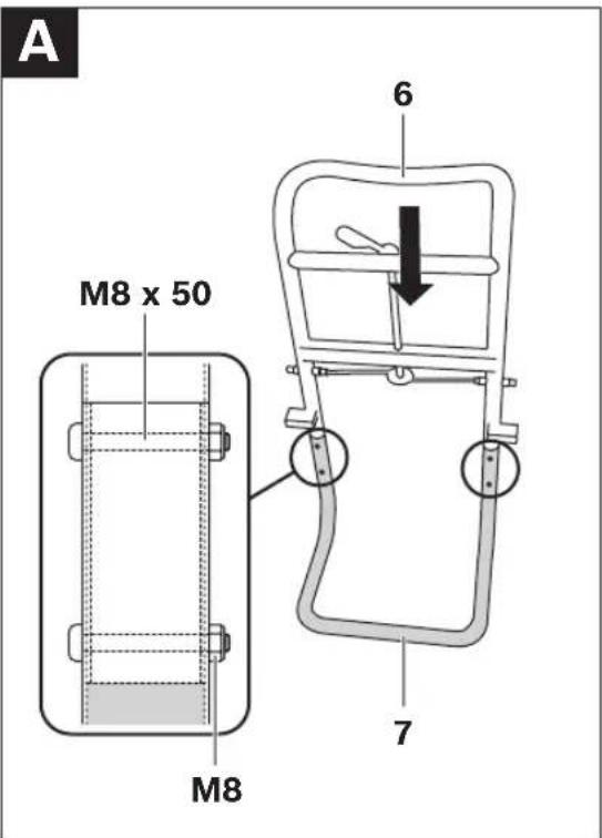
For Fig. A:
- Bolt the upper frame 6 and the bottom frame 7 together.
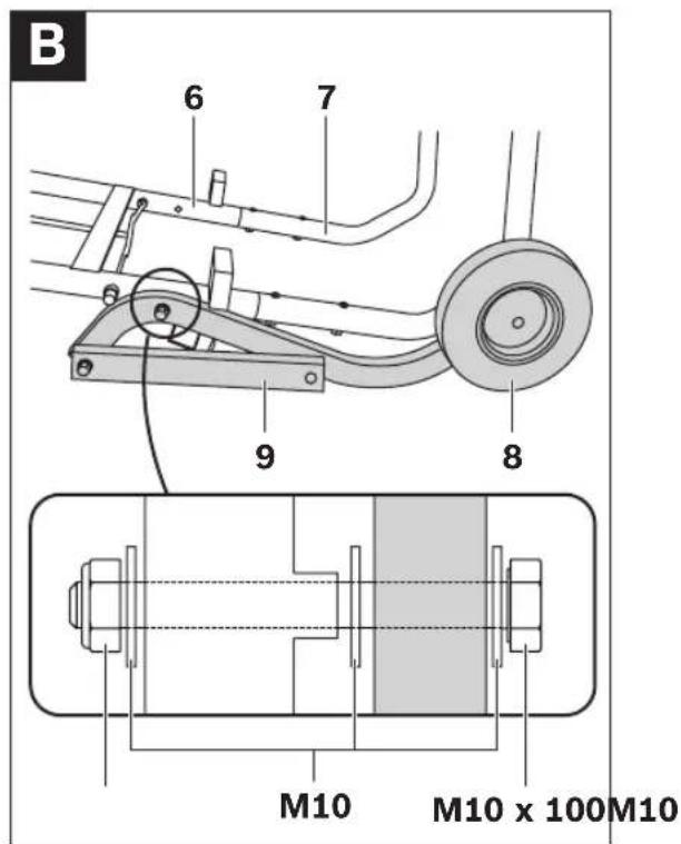
For Fig. B:
- Screw both the left and right wheel 8 to the upper frame 6.
Pay attention that the linkage bars 9 face outward and that the tires of the wheels face toward the bottom frame 7.
Note: Do not over-tighten the nuts. Parts bolted together must move freely.
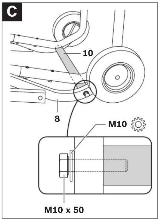
For Fig. C:
- Bolt the foot lever 10 to both wheels 8.
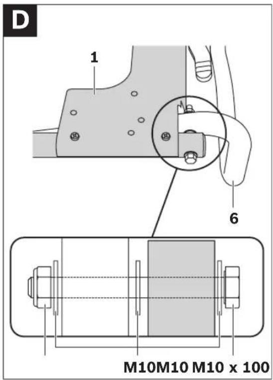
For Fig. D:
- Screw the mounting plate 1 on both sides to the upper frame 6.
Note: Do not over-tighten the nuts. Parts bolted together must move freely.
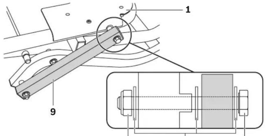
For Fig. E:
- Bolt the left and right linkage bar 9 each to the mounting plate 1.
Note: Do not over-tighten the nuts. Parts bolted together must move freely.
16 | English
Preparing the Saw Stand
Setting Up the Saw Stand (see figure F)
Before fastening the power tool, the stand base must be pulled apart.
- To relieve the limit bolts 4, lightly pull the saw stand upward by the handle 3.
- Release lock 2. This pulls back the limit bolts that lock the wheels in place.
- Position one foot on the foot lever 10 and push the handle 3 downward with both hands until the limit bolts engage again.
- Close the lock 2.
The height-adjustable legs 5 are used for levelling the saw stand.
- Loosen lock nut 12 and screw the legs in or out until the saw stand is aligned level.
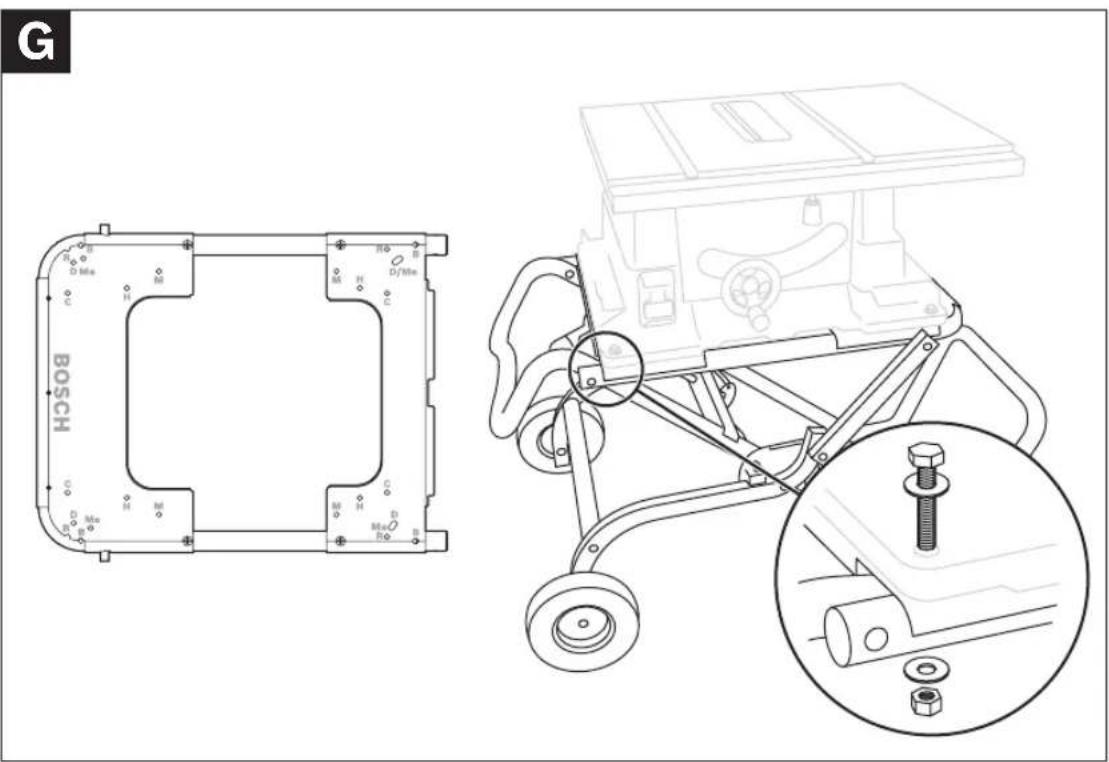
Fastening the Power Tool to the Mounting Plate (see figure G)
The mounting plate 1 is universally usable. With the varying mounting holes, both Bosch power tools as well as other brands can be mounted to the saw stand.
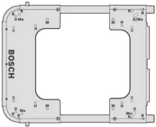
| Brand Model | Mounting hole | |
| Bosch | GTS 10 B | |
| DeWALT | DW744XP D | |
| Metabo | TS 250 Me | |
| Makita | 2703 M | |
| Hitachi | C 10 RA 2 H | |
- Position the power tool onto the matching mounting holes.
- Screw the mounting plate and the power tool together with the fitting bolts, washers and nuts.
Operation
Working Advice
Do not overload the saw stand. Always observe the maximum carrying capacity of the saw stand.
Before working, always make sure that the lock 2 is closed.
Always hold the workpiece firmly, especially the longer and more heavy section. After cutting through the workpiece, the centre of gravity may become dislocated in such an unfavourable manner that the saw stand tips over.
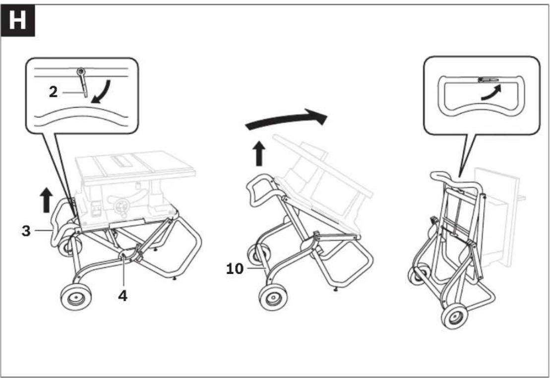
Transport
The stand base must be folded together for transport. (see figure H)
- To relieve the limit bolts 4, lightly push the saw stand downward by the handle 3.
- Release lock 2. This pulls back the limit bolts that lock the wheels in place.
- Position one foot on the foot lever 10 and push the handle 3 upward with both hands until the limit bolts can engage again.
- Close the lock 2.
Maintenance and Service
Maintenance and Cleaning
If the saw stand should fail despite the care taken in manufacture and testing, repair should be carried out by an authorised customer services agent for Bosch power tools.
In all correspondence and spare parts orders, please always include the 10-digit article number given on the type plate of the saw stand.
Wheel Inflation Pressure
The wheels are provided with an inflation pressure of 1.7–2 bar. The maximum wheel inflation pressure is 2.5 bar.
After-sales Service and Customer Assistance
Our after-sales service responds to your questions concerning maintenance and repair of your product as well as spare parts. Exploded views and information on spare parts can also be found under:
www.bosch-pt.com
Our customer consultants answer your questions concerning best buy, application and adjustment of products and accessories.
Great Britain
Robert Bosch Ltd. (B.S.C.)
P.O. Box 98
Broadwater Park
North Orbital Road
Denham
Uxbridge
UB 9 5HJ
Tel. Service: +44 (0844) 736 0109
Fax: +44 (0844) 736 0146
Australia, New Zealand and Pacific Islands
Robert Bosch Australia Pty. Ltd.
Power Tools
Locked Bag 66
Clayton South VIC 3169
Customer Contact Center
Inside Australia:
Phone: +61 (01300) 307 044
Fax: +61 (01300) 307 045
Inside New Zealand:
Phone: +64 (0800) 543 353
Fax: +64 (0800) 428 570
Outside AU and NZ:
Phone: +61 (03) 9541 5555
www.bosch.com.au
Disposal
The saw stand, accessories and packaging should be sorted for environmental-friendly recycling.
Subject to change without notice.


18 | Français
| Fabricant Modèle | Alésage de montage | |
| Bosch | GTS 10 B | |
| DeWALT | DW744XP D | |
| Metabo | TS 250 Me | |
| Makita | 2703 M | |
| Hitachi | C 10 R A 2 H | |
Robert Bosch (France) S.A.S.
| Fabricante Modelo | Agujero de sujeción | |
| Bosch | GTS 10 B | |
| DeWALT | DW744XP D | |
| Metabo | TS 250 Me | |
| Makita | 2703 M | |
| Hitachi | C 10 R A 2 H | |
| Fabricante Modelo | Orificios de montagem | |
| Bosch | GTS 10 B | |
| DeWALT | DW744XP D | |
| Metabo | TS 250 Me | |
| Makita | 2703 M | |
| Hitachi | C 10 R A 2 H | |
| Fabrikant Type | Montage-boorgat | |
| Bosch | GTS 10 B | |
| DeWALT | DW744XP D | |
| Metabo | TS 250 Me | |
| Makita | 2703 M | |
| Hitachi | C 10 RA 2 H | |
| Producent Model | Monterings-boring | |
| Bosch | GTS 10 B | |
| DeWALT | DW744XP D | |
| Metabo | TS 250 Me | |
| Makita | 2703 M | |
| Hitachi | C 10 R A 2 H | |
Bosch Service Center
Telegrafvej 3
2750 Ballerup
Tel. Service Center: +45 (4489) 8855
Fax: +45 (4489) 87 55
E-Mail: vaerktoej@dk.bosch.com
Bortskaffelse
| Tillverkare Modell | Monte-ringshål | |
| Bosch | GTS 10 B | |
| DeWALT | DW744XP D | |
| Metabo | TS 250 Me | |
| Makita | 2703 M | |
| Hitachi | C 10 R A 2 H | |
Bosch Service Center
Telegrafvej 3
2750 Ballerup
Danmark
Tel.: +46 (020) 41 44 55
Fax: +46 (011) 18 76 91
Avfallshantering
| Produsent Modell | Montasje-boring | |
| Bosch | GTS 10 B | |
| DeWALT | DW744XP D | |
| Metabo | TS 250 Me | |
| Makita | 2703 M | |
| Hitachi | C 10 R A 2 H | |
Bosch San. ve Tic. A.S.
Ahi Evran Cad. No:1 Kat:22
Polaris Plaza
80670 Maslak/Istanbul
Robert Bosch Sp. z o.o.
Česky | 77
| Výrobce Model | Montážní otvor | |
| Bosch | GTS 10 B | |
| DeWALT | DW744XP D | |
| Metabo | TS 250 Me | |
| Makita | 2703 M | |
| Hitachi | C 10 R A 2 H | |
Bosch Service Center PT
K Vápence 1621/16
692 01 Mikulov
Tel.: +420 (519) 305 700
Fax: +420 (519) 305 705
E-Mail: servis.naradi@cz.bosch.com
www.bosch.cz
Zpracování odpadů
| Výrobca Model | Montážny otvor | |
| Bosch | GTS 10 B | |
| DeWALT | DW744XP D | |
| Metabo | TS 250 Me | |
| Makita | 2703 M | |
| Hitachi | C 10 R A 2 H | |
| Виробник Модель | Монтажнийотвір | |
| Bosch | GTS 10 B | |
| DeWALT | DW744XP D | |
| Metabo | TS 250 Me | |
| Makita | 2703 M | |
| Hitachi | C 10 RA 2 H | |
| Producător Model | Gaură de montaj | |
| Bosch | GTS 10 B | |
| DeWALT | DW744XP D | |
| Metabo | TS 250 Me | |
| Makita | 2703 M | |
| Hitachi | C 10 R A 2 H | |
Bosch Service Center
Str. Horia Măcelariu Nr. 30–34,
013937 Bucureşti
Tel. Service scule electrice: +40 (021) 4 05 75 40
Fax: +40 (021) 4 05 75 66
E-Mail: infoBSC@ro.bosch.com
| Производител Модел | Монтажен отвор | |
| Bosch | GTS 10 B | |
| DeWALT | DW744XP D | |
| Metabo | TS 250 Me | |
| Makita | 2703 M | |
| Hitachi | C 10 RA 2 H | |
| Proizvodjač Model | Montažni otvor | |
| Bosch | GTS 10 B | |
| DeWALT | DW744XP D | |
| Metabo | TS 250 Me | |
| Makita | 2703 M | |
| Hitachi | C 10 R A 2 H | |
- Pozicionirajte električni alat na odgovarajuće montažne otvore.
- Zavrnite montažnu ploču i električni alat sa odgovarajućim zavrtnjima, platnama podmetačima i navrtkama.
Srpski | 111
Rad
Uputstva za rad
| Proizvajalec Model | Montažna izvrtina | |
| Bosch | GTS 10 B | |
| DeWALT | DW744XP D | |
| Metabo | TS 250 Me | |
| Makita | 2703 M | |
| Hitachi | C 10 R A 2 H | |
| Proizvođač Model | Montažni provrt | |
| Bosch | GTS 10 B | |
| DeWALT | DW744XP D | |
| Metabo | TS 250 Me | |
| Makita | 2703 M | |
| Hitachi | C 10 R A 2 H | |
- Pozicionirajte električni alat na odgovarajuće montažne provrte.
- Vijčano spojite montažnu ploču i električni alat sa odgovarajućim vijcima, podložnim pločicama i maticama.
120 | Hrvatski
Rad
Upute za rad
Ne preopterećujte radni stol. Pazite uvijek na maksimalnu nosivost radnog stola.
Tootja Mudel Montaažiava
| Bosch | GTS 10 B |
| DeWALT | DW744XP D |
| Metabo | TS 250 Me |
| Makita | 2703 M |
| Hitachi | C 10 R A 2 H |
| Gamintojas Modelis | Montavimo kiaurymė | |
| Bosch | GTS 10 B | |
| DeWALT | DW744XP D | |
| Metabo | TS 250 Me | |
| Makita | 2703 M | |
| Hitachi | C 10 R A 2 H | |