
GTA 2600 Professional - Service après-vente BOSCH - Free user manual and instructions
Find the device manual for free GTA 2600 Professional BOSCH in PDF.

User questions about GTA 2600 Professional BOSCH
0 question about this device. Answer the ones you know or ask your own.
Ask a new question about this device
Download the instructions for your Service après-vente in PDF format for free! Find your manual GTA 2600 Professional - BOSCH and take your electronic device back in hand. On this page are published all the documents necessary for the use of your device. GTA 2600 Professional by BOSCH.
USER MANUAL GTA 2600 Professional BOSCH
OHJ BUCII-843-004.book Page 1 Thursday, January 12, 2017 9:31 AM
natural_image
Technical line drawing of a mechanical clamp or support device (no text or symbols)Robert Bosch Power Tools GmbH
70538 Stuttgart
GERMANY
www.bosch-pt.com
1609 92A 2MA (2017.01) T/105

GTA 2600 Professional

BOSCH
OBJ_BUCH-843-004.book Page 3 Thursday, January 12, 2017 11:27 AM
|3
Bosch Power Tools 1 609 92A 2MA | (12.1.17)
4

natural_image
Technical line drawing of a mechanical frame or support structure (no text or symbols)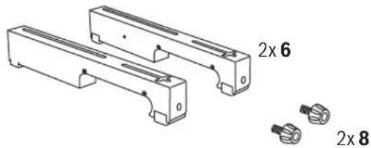
natural_image
Technical line drawing of two mechanical components with multiple bolted connectors and a separate pair of 2x8 connectors (no text or symbols present)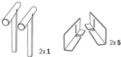
natural_image
Two technical line drawings of cylindrical and rectangular components, labeled 2x1 and 2x5 (no text or symbols on the shapes themselves)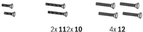

natural_image
Two isometric view diagrams of rectangular electronic components with square holes, labeled 2x182x17 below (no text or symbols on the diagrams themselves)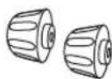
6
OBJ_BUCH-843-004.book Page 7 Thursday, January 12, 2017 11:27 AM
17
Bosch Power Tools 1 609 92A 2MA | (12.1.17)
8 | Deutsch
Deutsch
Sicherheitshinweise
General Safety Rules

Read all warning notes and instructions enclosed with the saw stand and the power tool to be mounted. Failure to follow the warnings and instructions may result in electric shock, fire and/or serious injury.
Safety Warnings for Saw Stands
▶ Pull the plug from the mains receptacle and/or remove the battery from the power tool before making adjustments on the tool or changing tool accessories. Unintentional switching on of the power tool is the cause of many accidents.
▶ Assemble the saw stand in the proper manner before mounting the power tool. Proper assembly is important to prevent the risk of a collapse of the saw stand.
▶ Attach the power tool securely to the saw stand before using it. Slipping off of the power tool on the saw stand can lead to loss of control.
Place the saw stand on a firm, level and horizontal surface. If the saw stand can slip off or wobbles, the power tool or the workpiece cannot be uniformly and securely guided.
▶ Do not overload the saw stand and do not use it as a ladder or scaffolding. Overloading or standing on the saw stand can lead to the upward shifting of the centre of gravity of the stand and its tipping over.
▶ When working or transporting, take care that all bolts and connecting elements are firmly tightened. The attachment sets for the power tool must always be firmly locked. Loose connections can lead to instability and inexact sawing.
Mount and dismount the power tool only when it is in the transport position (for instructions on the transport position, also see the operating instructions of the respective power tool). Otherwise, the power tool can have such an unfavourable centre of gravity that it cannot be held securely.
When the power tool is mounted to the attachment set, operate it exclusively on the saw stand. Without the saw stand, the attachment set with the power tool does not stand securely and can tip over.
▶ Ensure that long and heavy workpieces do not affect the equilibrium of the saw stand. Long and/or heavy workpieces must be supported at the free end.
- Keep your fingers clear of the hinge points while pushing the saw stand together or pulling it apart. Danger of fingers being crushed or contused.
▶ Observe valid national and international standards.


12 | English
Symbols
The following symbols can be important for the operation of your saw stand. Please memorise the symbols and their meanings. The correct interpretation of the symbols helps you operate the saw stand better and more secure.
Symbol Meaning
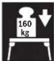
The maximum carrying capacity (power tool + workpiece) of the saw stand is 160 kg.
Product Description and Specifications
Intended Use
The saw stand is intended exclusively for mounting the following stationary Bosch saws (as of 2010.05):
- GCM 8 S 3 601 L16 0..
- GCM 8 SJ 3 601 L16 2..
- GCM 800 S 3601 L16 1..
-GCM 10 0 601 B20 0..
-GCM10J
GCM 10 M 3 601 M20 2..
- GCM 10 S 0 601 B20 5..
- GCM 10 SD 0601 B225..
-GCM 120601 B210.. - GCM 12 SD 0601 B235.
-GTM12 3601M150..
Together with the power tool, the saw stand is intended for the cutting to length of boards and profiles.
Product Features
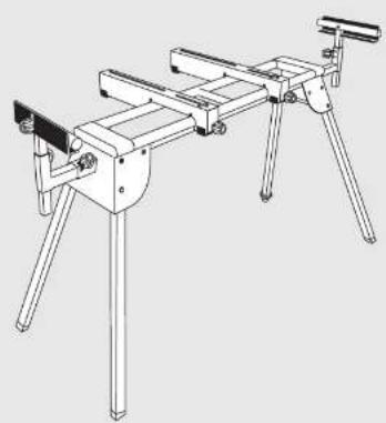
The numbering of the product features refers to the illustration of the saw stand on the graphics pages.
1 Workpiece support
2 Table extension
3 Locking knob of the table extension 2
4 Locking knob of the length stop 5
5 Material stop
6 Attachment set
7 Locking knob of the workpiece support 1
8 Locking knob of the attachment set 6
9 Height-adjustable leg
10 Carriage bolt M8 x 26
11 Carriage bolt M6 x 46
12 Carriage bolt M8 x 44
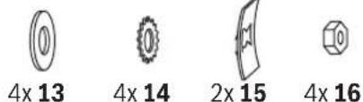
13 Washer
14 Lock washer
15 Nut locking device
16 Nut
17 Assembly-sliding plate
18 Assembly-sliding plate with slot
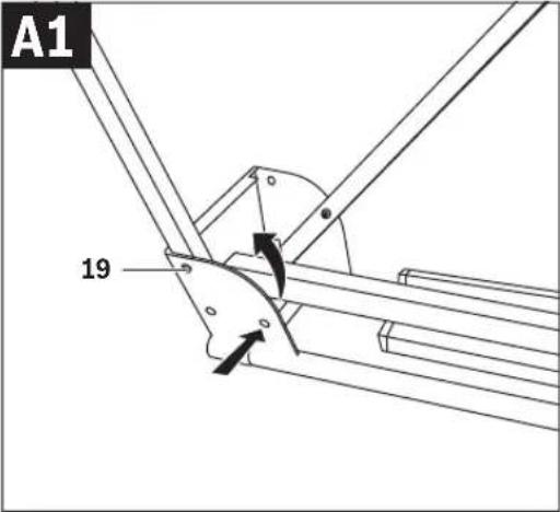
19 Locking pin
20 Lock nut
21 Adjustment screw of the attachment set 6
Accessories shown or described are not part of the standard delivery scope of the product. A complete overview of accessories can be found in our accessories program.
Technical Data
| Saw stand GTA 2600 | ||
| Article number | 3 601 M12 300 | |
| Length of saw stand without table extension | mm 1220 | |
| Length of saw stand with table extension | mm 2620 | |
| Height of saw stand | mm | 820 |
| Max. carrying capacity (power tool + workpiece) without table extension | ||
| - Attachment set | kg | 160 |
| Max. carrying capacity (power tool + workpiece) with table extension | ||
| - Attachment set | kg | 110 |
| - Per table extension | kg | 25 |
| Weight according to EPTA-Procedure 01:2014 | kg | 19.6 |
Assembly
Delivery Scope

Please also observe the representation of the delivery scope at the beginning of the operating instructions.
Before assembling the saw stand, check if all parts listed below are provided:
| No. | Designation | Quantity |
| Saw stand GTA 2600 | 1 | |
| 6 | Attachment set | 2 |
| 8 | Locking knob of the attachment set 6 | 2 |
| 1 | Workpiece support | 2 |
| 5 | Length stop | 2 |


English | 13
No. Designation Quantity
| Fastening kitconsisting of:- Carriage bolt | ||
| 10 | M8 x 26 | 2 |
| 11 | M6 x 46 | 2 |
| 12 | M8 x 44 | 4 |
| 13 | - Washer | 4 |
| 14 | - Lock washer | 4 |
| 15 | - Nut locking device | 2 |
| 16 | - Nut | 4 |
| 17 | - Assembly-sliding plate | 2 |
| 18 | - Assembly-sliding plate with slot | 2 |
| 4 | - Locking knob of the length stop | 2 |
Additionally required tools (not in delivery scope):
- Cross-head screwdriver
- Adjustable spanner
Assembling the Saw Stand
Carefully remove all parts included in the delivery from their packaging.
Remove all packaging material.
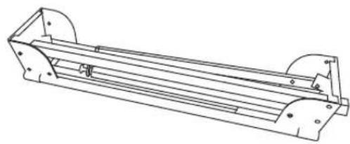
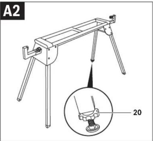
Setting Up the Saw Stand (see figures A1 - A2)
Lay the saw stand upside down on the floor (legs facing upward).
Push the locking pin 19 in and tilt the leg upward until the locking pin can be heard to engage.
Repeat this workstep with the other three legs.
Turn around the saw stand to the working position.
Ensure that the saw stand is stable and that all locking pins have engaged.
The saw stand is easily aligned with the height-adjustable leg 9.
Loosen lock nut 20 and screw the leg in or out until the saw stand is aligned level and all four legs face against the floor.
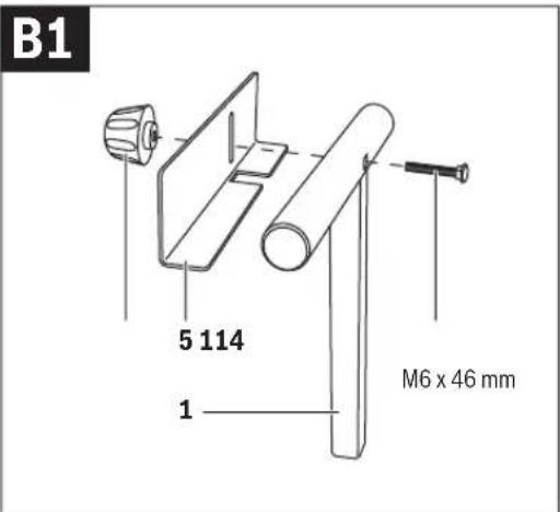
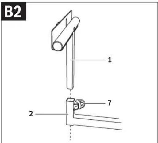
Mounting the Length Stop and Workpiece Support (see figures B1-B2)
Screw the length stop 5 to the workpiece support 1 with carriage bolt 11 and locking knob 4.
Insert the workpiece support 1 into the table extension 2.
Tighten the locking knob 7 to lock the workpiece support.
Repeat the worksteps with the second workpiece support.
Preparing the Saw Stand
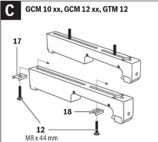
Preparing the Attachment Sets (see figure C) for GCM 10 xx, GCM 12 xx, GTM 12
Insert one carriage bolt 12 each through assembly-sliding plate 17 and 18.
Position assembly-sliding plate 17 with the carriage bolt in the rear slot of the attachment set.
Position assembly-sliding plate 18 with the carriage bolt in the front slot of the attachment set.
Repeat the worksteps with the second attachment set.
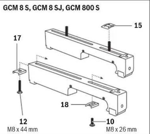
for GCM 8 S, GCM 8 SJ, GCM 800 S
Insert one carriage bolt 12 through assembly-sliding plate 17 and one carriage bolt 10 through assembly-sliding plate 18. Position assembly-sliding plate 17 with the carriage bolt in the rear slot of the attachment set.
Position assembly-sliding plate 18 with the carriage bolt in the front slot of the attachment set and secure the carriage bolt with the nut locking device 15 against falling out.
Repeat the worksteps with the second attachment set.
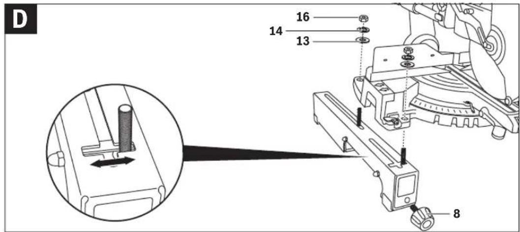
Fastening the Power Tool to the Attachment Sets (see figure D)
Position the power tool in the transport position. Notes on the transport position are given in the operating instructions of the respective power tool.
Raise one side of the power tool and position the carriage bolts of the attachment set at the correct distance to the mounting holes of the power tool.
Note: Power tools with off-set mounting holes can also be fastened with help of the slot in the assembly-sliding plate 18 and the lateral slot in the attachment set 6.
Lower the power tool onto the carriage bolts and loosely screw the attachment set and the power tool together with the washers 13, lock washers 14 and nuts 16.
Screw the locking knob 8 into the corresponding hole of the attachment set 6.
Repeat the worksteps with the second attachment set.
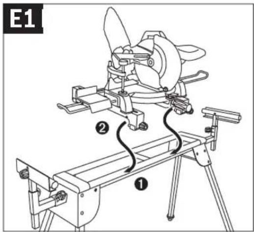
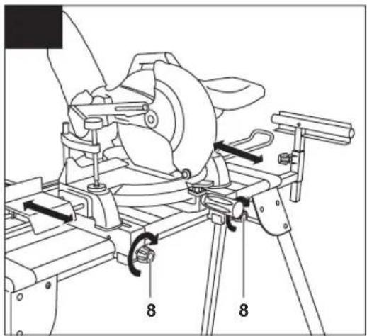
Fastening the Attachment Sets with the Power Tool onto the Saw Stand (see figures E1 - E2)
Align both attachment sets parallel to each other.
Position the power tool centred on the saw stand in the sequence shown. Firstly, allow the rounded-off part of the attachment sets to rest against the front rail (1), then slowly and carefully lower the power tool (2) until it is seated securely on the rear rail.
If required, move the power tool on the attachment sets 6 so that the weight is positioned centrally on the saw stand.
Now, firmly tighten the nuts 16 for final fastening of the power tool.
Afterwards, firmly tighten both locking knobs 8 of the attachment sets.
Operation
Working Advice
Do not overload the saw stand. Always observe the maximum carrying capacity of the saw stand and the two table extensions.
Always hold the workpiece firmly, especially the longer and more heavy section. After cutting through the workpiece, the centre of gravity may become dislocated in such an unfavourable manner that the saw stand tips over.


14 | English
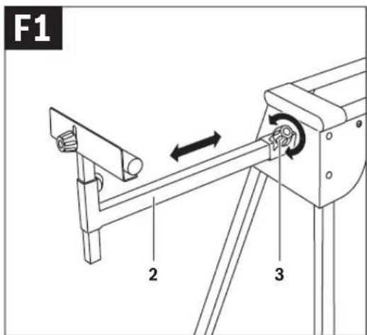
Extending the Saw Stand (see figures F1 - F2)
Long workpieces must be underlaid or supported at their free end.
Place your long workpiece onto the saw table of the power tool.
Loosen locking knob 3 and pull the table extension 2 out to the desired clearance.
Retighten the locking knobs again.
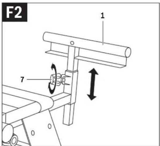
Loosen locking knob 7 and adjust the height of the workpiece support 1 so that the workpiece rests level.
Retighten the locking knobs again.
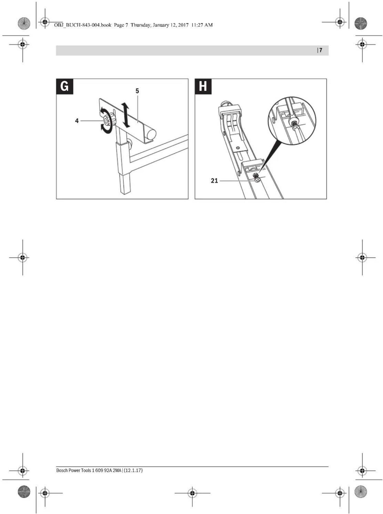
Sawing Workpieces of the Same Length (see figure G)
The material stop 5 can be used for easily sawing workpieces to the same length.
Loosen locking knob 4 and position the length stop 5 to the desired clearance to the saw blade of the power tool.
Retighten the locking knobs again.
Adjusting the Attachment-set Bracket (see figure H)
After intensive use of the saw stand, the bracket that locks the attachment set 6 to the saw table via the the locking knob 8 may possibly require readjustment.
Remove the power tool from the attachment sets.
Turn the attachment set upside down.
When the attachment set cannot be locked to the saw stand despite firmly tightening the locking knob, screw the adjustment screw 21 in clockwise direction.
When the attachment set does not fit onto both rails (front and rear) of the saw stand at the same time, screw the adjustment screw 21 in anticlockwise direction.
Check the firm and correct seating of the attachment set and repeat the adjustment, if required.
Repeat the worksteps with the second attachment set.
Maintenance and Service
After-sales Service and Application Service
Our after-sales service responds to your questions concerning maintenance and repair of your product as well as spare parts. Exploded views and information on spare parts can also be found under:
www.bosch-pt.com
Bosch's application service team will gladly answer questions concerning our products and their accessories.
In all correspondence and spare parts orders, please always include the 10-digit article number given on the nameplate of the product.
Great Britain
Robert Bosch Ltd. (B.S.C.)
P.O. Box 98
Broadwater Park
North Orbital Road
Denham
Uxbridge
UB 9 5HJ
At www.bosch-pt.co.uk you can order spare parts or arrange the collection of a product in need of servicing or repair.
Tel. Service: (0344) 7360109
E-Mail: boschservicecentre@bosch.com
Ireland
Origo Ltd.
Unit 23 Magna Drive
Magna Business Park
City West
Dublin 24
Tel. Service: (01) 4666700
Fax: (01) 4666888
Australia, New Zealand and Pacific Islands
Robert Bosch Australia Pty. Ltd.
Power Tools
Locked Bag 66
Clayton South VIC 3169
Customer Contact Center
Inside Australia:
Phone: (01300) 307044
Fax: (01300) 307045
Inside New Zealand:
Phone: (0800) 543353
Fax: (0800) 428570
Outside AU and NZ:
Phone: +61 3 95415555
www.bosch.com.au
Republic of South Africa
Customer service
Hotline: (011) 6519600
Gauteng - BSC Service Centre
35 Roper Street, New Centre
Johannesburg
Tel.: (011) 4939375
Fax: (011) 4930126
E-Mail: bsctools@icon.co.za
KZN - BSC Service Centre
Unit E, Almar Centre
143 Crompton Street
Pinetown
Tel.: (031) 7012120
Fax: (031) 7012446
E-Mail: bsc.dur@za.bosch.com
Western Cape - BSC Service Centre
Democracy Way, Prosperity Park
Milnerton
Tel.: (021) 5512577
Fax: (021) 5513223
E-Mail: bsc@zsd.co.za


Français | 15
Bosch Headquarters
Midrand, Gauteng
Tel.: (011) 6519600
Fax: (011) 6519880
E-Mail: rbsa-hq.pts@za.bosch.com
Disposal
The saw stand, accessories and packaging should be sorted for environmental-friendly recycling.
Subject to change without notice.
Français
Robert Bosch (France) S.A.S.
Bosch Service Center
Telegrafvej 3
2750 Ballerup
På www.bosch-pt.dk kan der online bestilles reservedele eller oprettes en reparations ordre.
Tlf. Service Center: 44898855
Fax: 44898755
E-Mail: vaerktoej@dk.bosch.com
Bortskaffelse
Bosch Service Center
Telegrafvej 3
2750 Ballerup
Danmark
Tel.: (08) 7501820 (inom Sverige)
Fax: (011) 187691
Avfallshantering
for GCM 10 xx, GCM 12 xx, GTM 12
for GCM 8 S, GCM 8 SJ, GCM 800 S
Robert Bosch Sp. z o.o.
Bosch Service Center PT
K Vápence 1621/16
692 01 Mikulov
Tel. service scule electrice: (021) 4057540
Fax: (021) 4057566
E-Mail: infoBSC@ro.bosch.com