
GTA 600 Professional - Service après-vente BOSCH - Free user manual and instructions
Find the device manual for free GTA 600 Professional BOSCH in PDF.

| Product type | Worktable for stationary saw |
| Brand | Bosch |
| Model | GTA 600 Professional |
| Article number | 3 601 M22 001 |
| Base frame dimensions | 450 x 520 mm |
| Table height | 602 mm |
| Weight | 6,3 kg |
| Maximum load capacity | 60 kg (power tool + workpiece) |
| Power supply | Not applicable (mechanical worktable) |
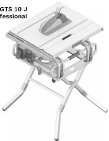
| Intended use | For integrating Bosch GTS 10 J Professional stationary saws (version 2011.01) and cutting boards and profiles |
| Main functions | Stable support for stationary saw, foldable for transport, adjustable feet |
| Included items | Base frame, 4 feet, mounting set (screws and nuts) |
| Assembly | Unfold the frame, insert and screw in the feet with a screwdriver and a 13 mm wrench |
| Safety | Disconnect tool before adjustment, do not overload, assemble on a flat surface, secure the tool firmly, do not use as a ladder |
| Maintenance and cleaning | Regular cleaning, repairs only by an authorized Bosch after-sales service |
| Spare parts and repairability | Exploded views and spare parts available at www.bosch-pt.com |
| After-sales service | France: 0 811 36 01 22 / sav.outillage-electroportatif@fr.bosch.com; Belgium: +32 070 22 55 65; Switzerland: +41 044 8 47 15 12 |
Frequently Asked Questions - GTA 600 Professional BOSCH
User questions about GTA 600 Professional BOSCH
0 question about this device. Answer the ones you know or ask your own.
Ask a new question about this device
Download the instructions for your Service après-vente in PDF format for free! Find your manual GTA 600 Professional - BOSCH and take your electronic device back in hand. On this page are published all the documents necessary for the use of your device. GTA 600 Professional by BOSCH.
USER MANUAL GTA 600 Professional BOSCH
OBJ_BUCH-1382-001.book Page 1 Thursday, January 13, 2011 9:15 AM

natural_image
3D rendering of a simple folding table with four legs and a square frame (no text or symbols)Robert Bosch GmbH
Power Tools Division
70745 Leinfelden-Echterdingen
Germany
www.bosch-pt.com
1 609 929 X94 (2011.01) PS / 95 UNI

GTA 600 Professional

BOSCH
natural_image
Technical illustration of a metal frame structure with multiple support rods and a separate inset showing a 3D box (no text or symbols)Bosch Power Tools 1 609 929 X94 | (13.1.11)
4
1 609 929 X94 | (13.1.11) Bosch Power Tools
GTS 10 J
Professional
natural_image
3D model of a folding table with metal legs and internal components (no text or symbols visible)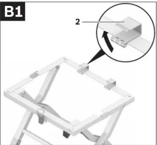
natural_image
Mechanical assembly diagram showing a bracket with mounting holes and a magnified inset highlighting a detail (no text or symbols)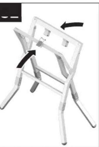
natural_image
3D diagram of a folding chair with black arrows indicating movement or change (no text or symbols)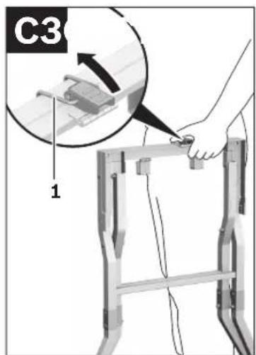
Bosch Power Tools 1 609 929 X94 | (13.1.11)
6 | Deutsch
Sicherheitshinweise
General Safety Rules

Read all warning notes and instructions enclosed with the saw stand and the power tool to be mounted. Failure to follow the warnings and instructions may result in electric shock, fire and/or serious injury.
Safety Warnings for Saw Stands
▶ Pull the plug from the mains receptacle and/or remove the battery from the power tool before making adjustments on the tool or changing tool accessories. Unintentional switching on of the power tool is the cause of many accidents.
▶ Assemble the saw stand in the proper manner before mounting the power tool. Proper assembly is important to prevent the risk of a collapse of the saw stand.
▶ Attach the power tool securely to the saw stand before using it. Slipping off of the power tool on the saw stand can lead to loss of control.
Place the saw stand on a firm, level and horizontal surface. If the saw stand can slip off or wobble, the workpiece cannot be uniformly and securely guided.
▶ Do not overload the saw stand and do not use it as a ladder or scaffolding. Overloading or standing on the saw stand can lead to the upward shifting of the centre of gravity of the stand and its tipping over.
▶ Do not ram the workpiece with force into the saw blade. When too much force is applied when using the power tool, the saw stand can be tipped over.
When working, take care that all bolts and connecting elements are firmly tightened. Loose connections can lead to instability and inexact sawing.
▶ Ensure that long and heavy workpieces do not affect the equilibrium of the saw stand. Long and/or heavy workpieces must be supported at the free end.
▶ Keep your fingers clear of the hinge points while pushing the saw stand together or pulling it apart. Danger of fingers being crushed or contused.
Symbols
The following symbols can be important for the operation of your saw stand. Please memorise the symbols and their meanings. The correct interpretation of the symbols helps you operate the saw stand better and more secure.
Symbol Meaning
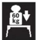
The maximum carrying capacity (power tool + workpiece) of the saw stand is 60 kg.
Product Description and Specifications
Intended Use
The saw stand is intended to accommodate the following stationary saws from Bosch (as of 2011.01):
- GTS 10 J Professional 3 601 M30 5..
Together with the power tool, the saw stand is intended for the cutting to length of boards and profiles.
Technical Data
| Saw stand GTA 600 | |
| Professional | |
| Article number | 3 601 M22 001 |
| Dimensions of base frame | mm 450 x 520 |
| Height of saw stand | mm 602 |
| Max. carrying capacity (power tool + work-piece) | kg 60 |
| Weight, approx. | kg 6.3 |
10 | English
Product Features
The numbering of the product features refers to the illustration of the saw stand on the graphics pages.
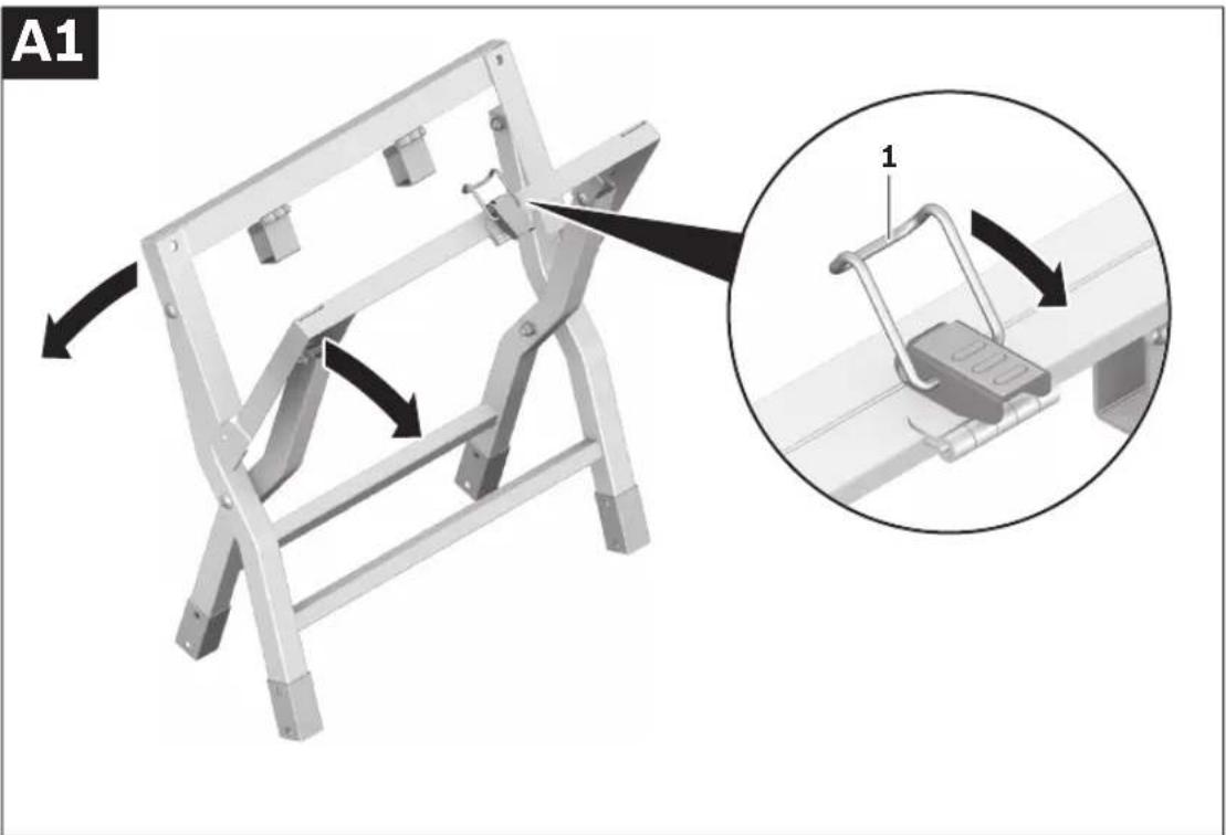
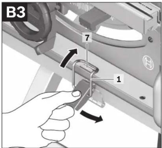
1 Tension latch
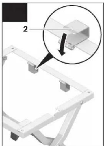
2 Retaining clamp
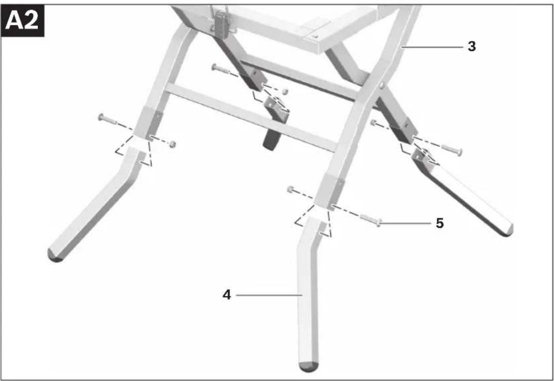
3 Base frame
4 Saw stand leg
5 Fastening kit
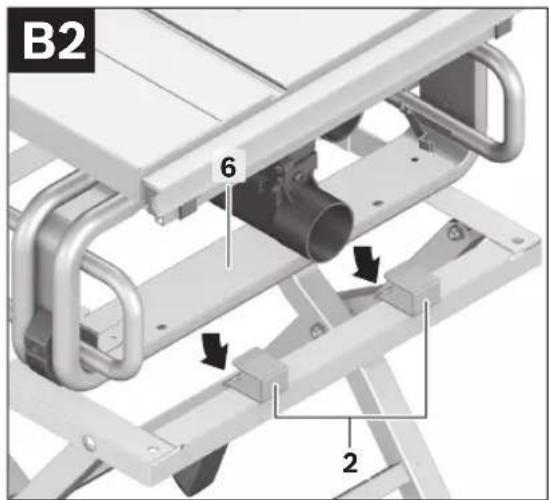
6 Housing frame (GTS 10 J Professional)
7 Strike (GTS 10 J Professional)
Accessories shown or described are not part of the standard delivery scope of the product. A complete overview of accessories can be found in our accessories program.
- Insert the saw stand legs 4 into the square tubing of base frame 3 until the mounting holes are aligned.
The saw stand legs must face outward. - Screw the saw stand legs and the base frame together with the screws and nuts of fastening kit 5.
Fastening the Power Tool (see figures B1-B3)
- Tilt both retaining clamps 2 upward.
- Slide the rear housing frame 6 of the power tool completely into the retaining clamps 2.
- Centre the power tool on the base frame.
- Hang the clip of tension latch 1 over strike 7 and fold down the latch to lock the power tool in place.
Assembly
Delivery Scope

Please also observe the representation of the delivery scope at the beginning of the operating instructions.
Before assembling the saw stand, check if all parts listed below are provided:
- Base frame 3
- Saw stand legs 4 (4 pcs.)
- Fastening kit 5 consisting of: Phillips screws M8 x 45 (4 pcs.), Lock nuts M8 (4 pcs.)
Additionally required tools (not in delivery scope):
- Phillips screwdriver
- Open-end spanner (13 mm)
Assembling the Saw Stand (see figures A1-A2)
- Carefully remove all parts included in the delivery from their packaging.
- Remove all packaging material.
- Undo tension latch 1 and pull the base frame 3 apart.
Operation
Working Advice
Do not overload the saw stand. Always observe the maximum carrying capacity of the saw stand.
Always hold the workpiece firmly, especially the longer and more heavy section. After cutting through the workpiece, the centre of gravity may become dislocated in such an unfavourable manner that the saw stand tips over.
Transport (see figures C1-C3)
- When folding the saw stand together or apart, the power tool may not be mounted to the saw stand.
The saw stand can be folded together for transport.
- Remove the power tool.
- Fold both retaining clamps 2 down.
- Fold the saw stand together.
- Hang the clip of tension latch 1 over the other side of base frame 3 and fold down the latch to lock the saw stand.
Maintenance and Service
Maintenance and Cleaning
If the saw stand should fail despite the care taken in manufacture and testing, repair should be carried out by an authorised customer services agent for Bosch power tools.
In all correspondence and spare parts orders, please always include the 10-digit article number given on the type plate of the saw stand.
Disposal
The saw stand, accessories and packaging should be sorted for environmental-friendly recycling.
After-sales Service and Customer Assistance
Our after-sales service responds to your questions concerning maintenance and repair of your product as well as spare parts. Exploded views and information on spare parts can also be found under: www.bosch-pt.com
Our customer service representatives can answer your questions concerning possible applications and adjustment of products and accessories.
Great Britain
Robert Bosch Ltd. (B.S.C.)
P.O. Box 98
Broadwater Park
North Orbital Road
Denham
Uxbridge
UB 9 5HJ
Tel. Service: +44 (0844) 736 0109
Fax: +44 (0844) 736 0146
E-Mail: boschservicecentre@bosch.com
Ireland
Origo Ltd.
Unit 23 Magna Drive
Magna Business Park
City West
Dublin 24
Tel. Service: +353 (01) 4 66 67 00
Fax: +353 (01) 4 66 68 88
Australia, New Zealand and Pacific Islands
Robert Bosch Australia Pty. Ltd.
Power Tools
Locked Bag 66
Clayton South VIC 3169
Customer Contact Center
Inside Australia:
Phone: +61 (01300) 307 044
Fax: +61 (01300) 307 045
Inside New Zealand:
Phone: +64 (0800) 543 353
Fax: +64 (0800) 428 570
Outside AU and NZ:
Phone: +61 (03) 9541 5555
www.bosch.com.au
Republic of South Africa
Customer service
Hotline: +27 (011) 6 51 96 00
Gauteng - BSC Service Centre
35 Roper Street, New Centre
Johannesburg
Tel.: +27 (011) 4 93 93 75
Fax: +27 (011) 4 93 01 26
E-Mail: bsctools@icon.co.za
KZN - BSC Service Centre
Unit E, Almar Centre
143 Crompton Street
Pinetown
Tel.: +27 (031) 7 01 21 20
Fax: +27 (031) 7 01 24 46
E-Mail: bsc.dur@za.bosch.com
Western Cape - BSC Service Centre
Democracy Way, Prosperity Park
Milnerton
Tel.: +27 (021) 5 51 25 77
Fax: +27 (021) 5 51 32 23
E-Mail: bsc@zsd.co.za
Bosch Headquarters
Midrand, Gauteng
Tel.: +27 (011) 6 51 96 00
Fax: +27 (011) 6 51 98 80
E-Mail: rbsa-hq.pts@za.bosch.com
Subject to change without notice.
12 | Français
Bosch Service Center
Telegrafvej 3
2750 Ballerup
Tel. Service Center: +45 (4489) 8855
Fax: +45 (4489) 87 55
E-Mail: vaerktoej@dk.bosch.com
Bortskaffelse
6 Husram (GTS 10 J Professional)
Bosch Service Center
Telegrafvej 3
2750 Ballerup
Danmark
Tel.: +46 (020) 41 44 55
Fax: +46 (011) 18 76 91
Avfallshantering
Bosch San. ve Tic. A.S.
Ahi Evran Cad. No:1 Kat:22
Polaris Plaza
80670 Maslak/Istanbul
Robert Bosch Sp. z o.o.
Bosch Service Center PT
K Vápence 1621/16
692 01 Mikulov
Tel.: +420 (519) 305 700
Fax: +420 (519) 305 705
E-Mail: servis.naradi@cz.bosch.com
www.bosch.cz
Zpracování odpadů
4) M8 x 45 ( expensive)
(4) M8 مهره
(GTS 10 J Professional) 6 (GTS 10 J Professional) 7
- GTA 600 Professional
- BOSCH
- | Deutsch
- Sicherheitshinweise
- General Safety Rules
- Safety Warnings for Saw Stands
- Symbols
- Product Description and Specifications
- Intended Use
- | English
- Product Features
- Fastening the Power Tool (see figures B1-B3)
- Assembly
- Delivery Scope
- Additionally required tools (not in delivery scope):
- Assembling the Saw Stand (see figures A1-A2)
- Operation
- Working Advice
- Transport (see figures C1-C3)
- Maintenance and Service
- Maintenance and Cleaning
- Disposal
- After-sales Service and Customer Assistance
- Great Britain
- Ireland
- Australia, New Zealand and Pacific Islands
- Republic of South Africa
- Customer service
- Gauteng - BSC Service Centre
- KZN - BSC Service Centre
- Western Cape - BSC Service Centre
- Bosch Headquarters
- | Français
- Bortskaffelse
- Avfallshantering
- Zpracování odpadů
Brand : BOSCH
Model : GTA 600 Professional
Category : Service après-vente