USER MANUAL RBC1000EX RYOBI
natural_image
Technical line drawing of a mechanical device with a magnified inset showing a detail (no text or symbols)
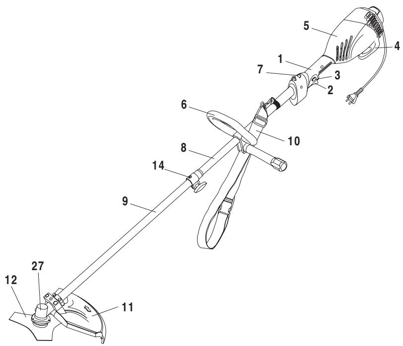
Fig. 1
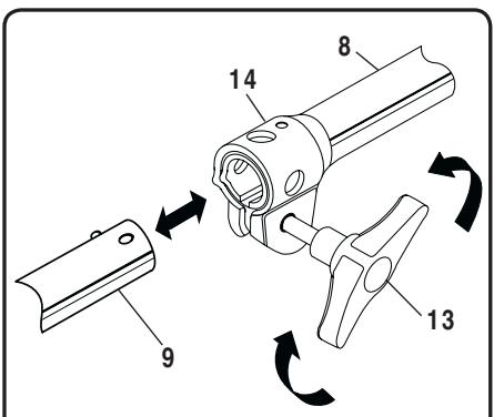
Fig. 2
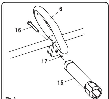
Fig. 3

natural_image
Line drawing of a person using a manual power shaver to clean grass, labeled as Fig. 9 (no text or symbols on the diagram itself)

natural_image
Illustration of a person using a power shaver to clean grass, labeled as Fig. 11 (no text on diagram)
natural_image
Mechanical assembly diagram showing a lever mechanism with labeled component 23 (no text or symbols beyond label)
natural_image
Mechanical assembly diagram showing a lever mechanism with a central hub and base component (no text or symbols)
| Attention ! | Il est indispensable que vous lisiez les instructions contenues dans ce manuel avant le montage et la mise en service de l'appareil. |
| Important! | It is essential that you read the instructions in this manual before mounting and operating this machine. |
| Achtung! | Bitte lesen Sie unbedingt vor Montage und Inbetriebnahme die Hinweise dieser Bedienungsanleitung. |
| ¡Atención! | Es imprescindible que lea las instrucciones de este manual antes del montaje y de la puesta en servicio. |
| Attenzione! | Prima di procedere al montaggio e alla messa in funzione, è indispensabile leggere attentamente le istruzioni del presente manuale. |
| Atenção! | É indispensável ler as instruções deste manual antes de montar e pôr em serviço. |
| Let op ! | Het is absoluut noodzakelijk vóór montage en inbedrijfstelling de aanwijzingen in deze handleiding te lezen. |
| Observera! | Det är nödvändigt att läsa instruktionerna i denna bruksanvisning före montering och driftsättning. |
| OBS! | Denne brugsanvisning skal læses igennem inden montering og ibrugtagning. |
| Advarsel! | Vennligst les instruksjonene i denne bruksanvisningen før du monterer og tar i bruk maskinen. |
| Huomio! | On ehdottoman välttämätöntä lukea tässä käyttöohjeessa annetut ohjeet ennen asennusta ja käyttöönottoa. |
| Προσοχή! | Eïvai antapaíτητο να διαβάσετε τις συστάσεις των οδηγιών αυτών πριν τη συναρμολόγηση και τη θέση σε λειτουργία |
| Figyelem! | Feltétlenül fontos, hogy a jelen használati útmutatóban foglalt előírásokat az összeszerelés és az üzembe helyezés ellőt elolvassa! |
| Dúležité upozornění! | Před montáží nářadí a uvedením do provozu je nutné si přečist následující pokyny. |
| Внимание! | Перед сборкой и запуском инструмента необходимо прочесть инструкции из настоящего руководства. |
| Atenție! | Este indispensabil să citiți instrucțiunile conținute în acest mod de utilizare înainte de montaj și de punerea în funcțiune. |
| Uwaga! | Przed montowaniem i uruchomieniem, koniecznie musicie się Państwo zapoznać z zaleceniami zawartymi w niniejszym sposobie użycia. |
| Pomembno! | Zelo pomembno je, da pred namestitvijo in prvo uporabo te naprave preberete navodila v tem priročniku. |
| Upozorenje! | Važno je da upute u ovom Korisničkom priručniku pročitate prije postavljanja i uporabe ovog alata. |
| Dikkat! | Montajdan ve aletin kullanımina başlamadan bu kılavuzda bulunan talimatları okumaniz gerekmektedir. |
| Tähtis! | Lugege enne seadme kokkupanekut ja kasutamist kindlasti läbi selles juhendis sisalduvad eeskirjad ja juhised! |
| Dèmesio! | Prieš surinkdami ir paleisdami aparatą į darba, reikia, kad jūs perskaitytumète šiame vadove esančias instrukcijas. |
| Uzmanību! | Ir łoti būtiski, lai jūs izlasītu norādījumus, kas sniegti šajā rokasgrāmatā, pirms ķeraties pie ierīces montēšanas un iedarbināšanas! |
| Upzornenie! | Je dôležité, aby ste si pred montážou a spustením zariadenia prečítali pokyny, ktoré sa nachádzajú v tomto návode. |
| Внимание! | Преди сглобяване и пускане на машината е важно да прочетете инструкциите в ръководството за употреба. |
Sous réserve de modifications techniques / Subject to technical modifications / Technische Änderungen vorbehalten / Bajo reserva de modificaciones técnicas / Con riserva di eventuali modifiche tecniche / Com reserva de modificações técnicas / Technische wijzigingen voorbehouden / Med förbehåll för tekniska ändringar / Med forbehold for tekniske ændringer / Med forbehold om tekniske endringer / Tekniset muutokset varataan / Упó тнүv επιφύλαξη τεχνικών τροποποιήσεων / A műszaki módosítás jogát fenntartjuk / Změny technických údajů vyhrazeny / Могут быть внесены технические изменения / Sub rezerva modificațiilor tehnice / Z zastrzeženiem modyfikacji technicznych / Tehnične spremembe dopuščene Podložno tehničkim promjenama / Teknik düzeltmeler hakkі saklıdır / Tehnilised muudatused võimalikud / Pasiliekant teisę daryti techninius pakeitimus / Paturam tiesības mainīt tehniskos raksturlielumus / Technické zmeny vyhradenė / Подлежи на технически модификации
Français
CONSIGNES DE SÉCURITÉ GÉNÉRALES

AVERTISSEMENT
natural_image
Symbol of a trash bin crossed out by two diagonal lines (no text or numbers present)
When using electric gardening appliances, basic safety precautions should always be followed to reduce the risk of fire, electric shock and personal injury, including the following:
READ ALL INSTRUCTIONS.
■ Be familiar with the controls and proper use of the product.
- Clear the work area before each use. Remove all objects, such as rocks, broken glass, nails, wire or string that can be thrown or become entangled in the cutting line.
■ Wear heavy, long pants, boots and gloves. Do not wear loose fitting clothing, short pants or go bare foot. Do not wear jewelry of any kind.
■ Secure hair above shoulder level to prevent entanglement in moving parts.
■ Do not allow children or untrained individuals to use this product.
- Keep all bystanders, especially children and pets, at least 15 m from the operating area.
■ Do not operate this product when you are tired, ill or under the influence of alcohol, drugs or medication.
■ Do not operate in poor lighting. Use the unit only in daylight or good artificial light.
- Keep firm footing and balance. Do not overreach. Overreaching can result in loss of balance or exposure to hazards.
- Keep all parts of your body away from moving parts.
■ Inspect the product before use. Replace any damaged parts before use.
■ Do not operate the product in damp or wet locations. Do not use the product in the rain.
■ Wear safety glasses or goggles when operating this product.
■ Use the right product. Use the product for the intended purpose only.
■ Do not handle the product with wet hands.
■ Do not use the product if the switch does not turn the product on or off. A product that cannot be controlled with the switch is dangerous and must be repaired.
■ Avoid accidental starting; never carry the product with your finger on the trigger.
■ Use common sense when using this product. Stay alert and pay attention to what you are doing.
■ Do not force the product. It will do a better job with less likelihood of a risk of injury when you operate it at the rate for which it was designed.
■ Before using the machine and after any impact, check for signs of wear or damage and repair as necessary.
- Keep the tool well maintained, fasteners tightened and worn parts replaced.
■ Pull the plug out immediately if the mains or extension lead is damaged or severed.
■ Disconnect the product from the power supply when it is not in use, before servicing and when changing accessories.
■ Take care against injury from any trimming device fitted with a line cut-off blade. After advancing new cutting line manually, always return the machine to its normal operating position and switch the motor on.
SPECIFIC SAFETY RULES
SPECIFIC TRIMMER SAFETY RULES
- Replace the trimmer head if cracked, chipped or damaged in any way. Be sure the trimmer head is properly installed and securely fastened.
■ Make sure all guards, deflectors and handles are properly and securely attached.
- Use only the manufacturer's replacement line in the trimmer head.
■ Never operate the product without the safety guard in place and in good condition.
■ Use the product for cutting grass and light weeds only. Do not use for any other purpose.
■ Before starting the product, position it so that the line does not come in contact with anything you do not intend to cut.
- Maintain a firm grip on both handles while trimming. Keep the trimmer head below waist level. Never cut with the trimmer head over 76 cm or more above the ground.
- Keep the working area free from wires, stones and debris.
■ Do not cut against hard objects. This could cause injury or damage the trimmer.
- Do not use the trimmer to cut grass which is not in contact with the ground; for example, do not cut grass which is on walls or rocks etc.
■ Always use your trimmer in an upright position.
- Keep hands away from the cutting line. Do not attempt to remove cut material or to hold material to be cut when the line is moving.
English
SPECIFIC SAFETY RULES
Be sure to unplug the product before clearing jammed material from the line. Do not grasp the line when picking up or holding the product.
■ Be cautious after turning off the product. The line coasts after turning off the product.
■ Do not switch the trimmer on in enclosed or poorly ventilated spaces or in the presence of inflammable and/or explosive substances such as liquids, gas and powders.
■ Do not cross roads or gravel paths with the trimmer still running.
■ Never fit metal cutting elements to the trimmer.
SPECIFIC SAFETY RULES FOR BRUSHCUTTER AND BLADE USE
■ Do not operate the brushcutter unless the blade guard is firmly secured in place and in good condition.
■ Use heavy gloves while installing or removing blades.
■ Do not attempt to touch or stop the blade when it is rotating.
■ A coasting blade can cause injury while it continues to spin after the unit is stopped or trigger released. Maintain proper control until the blade has completely stopped rotating.
■ Replace any blade that has been damaged. Always make sure blade is installed correctly and securely fastened before each use. Failure to do so can cause serious injury.
■ Use only the manufacturer's replacement TRI-ARC blade intended for use on this brushcutter. Do not use any other blade.
■ The TRI-ARC blade is suited for cutting pulpy weeds and vines only. Do not use for any other purpose. Never use the TRI-ARC blade to cut woody brush.
Exercise extreme caution when using the blade with this unit. Blade thrust is the reaction that may occur when the spinning blade contacts anything it cannot cut. This contact may cause the blade to stop for an instant, and suddenly “thrust” the unit away from the object that was hit. This reaction can be violent enough to cause the operator to lose control of the unit. Blade thrust can occur without warning if the blade snags, stalls, or binds. This is more likely to occur in areas where it is difficult to see the material being cut. For cutting ease and safety, approach the weeds being cut from the right to the left. In the event an unexpected object or woody stock is encountered, this could minimize the blade thrust reaction.
■ Never cut any material over 13 mm diameter.
■ Always wear the shoulder strap when using the brushcutter and adjust to a comfortable operating position. Maintain a firm grip on both handles while cutting with a blade. Keep the blade away from body and below waist. Never use the brushcutter with the blade located 76 cm or more above the ground level.
ELECTRICAL SAFETY RULES
■ Make sure the cord is located so that it will not be stepped on, tripped over or otherwise subjected to damage or stress.
- Do not abuse the power cord. Never carry the product by the cord. Never pull the plug out of the power point by the cord. Keep the cord away from heat, oil and sharp edges.
■ For outdoors work use only suitably approved extension cables with a min. conductor cross section of 1.5 mm ^2 The plug connectors must have earthing contacts and be rain-water-proof.
- Inspect extension cords for deterioration, cuts or cracks in the insulation. Repair or replace the cords if any defects appear.
- A nameplate on the product indicates the unit's voltage. Never connect the product to an AC voltage that differs from this voltage.
■ If the power cord or extension cable becomes damaged during use, disconnect the cord from the supply immediately. DO NOT TOUCH THE CORD BEFORE DISCONNECTING THE SUPPLY.
■ Electrical power should be supplied via a Residual Current Device (RCD) with a tripping current of not more than 30 mA.
MAINTENANCE RULES
- Maintain the product with care. Follow instructions for changing accessories. Keep the product dry, clean and free from oil and grease.
■ Unplug the product before making adjustments or repairs.
■ Do not use the product if parts have been damaged.
- Check the product regularly to make sure that it will operate properly and perform the intended function. Check for alignment of moving parts, binding of moving parts, breakage of parts and any other condition that may affect the unit operation. Inspect the unit's power connection. Any part that is damaged should be properly repaired or replaced by a Ryobi authorized service centre.
- Keep the product clean of grass clippings and other materials that may become lodged in the cutting lines and air vents.
English
SPECIFIC SAFETY RULES
■ Never douse or squirt the product with water or any other liquid. Do not use detergents or solvents. Keep handles dry, clean and free from debris.
■ After each use, clean with a soft, dry cloth.

WARNING
Before carrying out any maintenance operations, cut off the electric power supply by disconnecting the plug from the mains.
■ If the cut-off blade is well worn or breaks, have this replaced by contacting an authorized service centre.
SERVICE RULES
■ Service on this product must be performed by qualified repair personnel only. Service or maintenance performed by unqualified personnel could result in injury to the user and/or damage to the product. Such service may also void your warranty.
■ Use only identical replacement parts when servicing the product. Follow the instructions in the Maintenance section of this manual. Use of unauthorized parts or failure to follow maintenance instructions may create a risk of shock, serious injury to the user and/or damage to the product. Such use may also void your warranty.
STORAGE AND TRANSPORTATION RULES
■ Stop the motor when you are waiting to cut or when you are walking from one cutting location to another.
■ Store the product inside in a dry place.
■ Store the product up high or lock it up to prevent unauthorized use or damage. Keep the product out of the reach of children.
■ Secure the product when transporting it.
■ Save these instructions. Refer to them frequently and use them to instruct others who may use this product. If you loan someone this product, loan these instructions also.
SYMBOLS
Some of the following symbols may be used on your tool. Please study them and learn their meaning. Proper interpretation of these symbols will allow you to operate the tool more safely and effectively.
| SYMBOL | NAME | EXPLANATION |
 | Safety Alert | Precautions that involve your safety. |
 | Ricochet | Thrown objects can cause severe injury. Wear protective clothing and boots. |
 | Do not use toothed blade | This unit is not intended for use with a toothed saw type blade. |
 | Ear and eye protection | Always wear ear and eye protection when operating this product. |
| [G3xH] | Keep Bystanders Away | Keep all bystanders at least 15 m away. |
 | Class II Construction | Double-insulated construction. |
 | Wet Conditions Alert | Do not expose to rain or use in damp locations. |
 | Read Operator's Manual | To reduce the risk of injury, user must read and understand operator's manual before using this product. |
English
SYMBOLS
| SYMBOL | NAME | EXPLANATION |
 | RPM (Revolutions Per Minute) | Operating speed of this product. |
 | Electric Shock Precaution | Remove plug from the mains immediately if cable is damaged or cut. |
The following signal words and meanings are intended to explain the levels of risk associated with this product.
| SYMBOL | SIGNAL | MEANING |
 | DANGER | Indicates an imminently hazardous situation, which, if not avoided, will result in death or serious injury. |
 | WARNING | Indicates a potentially hazardous situation, which, if not avoided, could result in serious injury. |
 | CAUTION | Indicates a potentially hazardous situation, which, if not avoided, may result in minor or moderate injury. |
| CAUTION | (Without Safety Alert Symbol) Indicates a situation that may result in property damage. |
SERVICE
Servicing requires extreme care and knowledge and should be performed only by a qualified service technician. For service we suggest you return the product to your nearest AUTHORIZED SERVICE CENTRE for repair. When servicing, use only identical replacement parts.

WARNING
Observe all normal safety precautions related to avoiding electrical shock.

WARNING
To avoid serious personal injury, do not attempt to use this product until you read thoroughly and understand completely the operator's manual. Save this operator's manual and review frequently for continuing safe operation and instructing others who may use this product.

WARNING
The operation of any power tool can result in foreign objects being thrown into your eyes, which can result in severe eye damage. Before beginning power tool operation, always wear safety goggles or safety glasses with side shields and a full face shield when needed. We recommend Wide Vision Safety Mask for use over eyeglasses or standard safety glasses with side shields. Always use eye protection.
SAVE THESE INSTRUCTIONS.
English
SPECIFICATIONS
Voltage.... 230-240 V\~50 Hz
Nameplate Power 1000 W
No Load Speed
- Brushcutter 7,000 min ^-1
- Trimmer 6,000 min ^-1
Cutting Line 2 mm
Max.Cutting Path
- Brushcutter 200 mm
- Trimmer 380 mm
Sound Pressure Level
- Brushcutter 88 dB(A)
- Trimmer 84 dB(A)
Sound Power Level
- Brushcutter 103 dB(A)
- Trimmer 96 dB(A)
Weight 4.8 kg
Vibration 8 m/s²
DESCRIPTION
See Fig. 1 to Fig. 14 for these parts.
-
Trigger handle
-
Trigger
-
Lock button
-
Cord retainer
-
Motor housing
-
Front handle
-
Livetool indicator
-
Upper shaft
-
Attachment shaft
-
Shoulder strap
-
Blade guard
-
Blade
-
Wing nut
-
Coupler
-
Barrier
-
Bolt
-
Washer
-
Screws
-
Bracket
-
Clip
-
Hanger
-
Bump knob
-
Cut off blade
-
Spool
-
Trimmer head
-
Drive connector
-
Gear head
-
Upper flange washer
-
Cupped washer
-
Blade nut
-
Mounting bracket
- Spring
- Cutting line
- Grass deflector
- Threaded mounting plate
ASSEMBLY
CONNECTING THE ATTACHMENT TO THE UPPER SHAFT (FIG.2)
The coupler (14) connects the attachment to the upper shaft.
Follow these steps to connect the attachment to the upper shaft.
■ Loosen the wing nut (13) by turning it counterclockwise.
■ Remove the end cap from the attachment shaft.
■ Align the button with the guide recess on the upper shaft.
■ Slide the attachment shaft (9) into the upper shaft (8) until the attachment shaft clicks into place.
Note: If the button does not release completely in the positioning hole, the shafts are not locked. Slightly rotate the attachment shaft until the button is locked into place.
■ Tighten the wing nut (13) securely by turning it clockwise.
Note: During operation, periodically check the wing nut (13) and tighten as necessary.
REMOVING THE ATTACHMENT FROM THE UPPER SHAFT (FIG.2)
Disconnect the upper shaft and attachment shaft for storage or when a job calls for a different attachment.
Follow these steps to remove the attachment from the upper shaft.
■ Release the trigger (2) and allow the trimmer to coast to a stop.
■ Unplug the tool.
■ Loosen the wing nut (13) by turning it counterclockwise.
■ Push the button, while pulling out the attachment.
ATTACHING THE FRONT HANDLE (FIG.3)
Follow these steps to attach the front handle.
■ Press the front handle (6) onto the upper shaft (8)
■ Place the front handle along the upper shaft to a position that allows for comfortable operation.
English
ASSEMBLY
■ Slide the bolt (16) through the hole in the front handle.
■ Slide the washer (17) onto the bolt.
■ Place the barrier handle (15) onto the bolt and tighten the barrier handle securely.
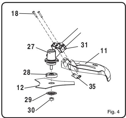
ATTACHING THE BLADE GUARD OR THE GRASS DEFLECTOR (FIG.4 & FIG.5)
Follow these steps to attach the blade guard (Fig. 4)
■ Attach the blade guard (11) to the mounting bracket (31).
■ Install two screws (18) from the top of the mounting bracket (31) through the blade guard (11) and into the threaded mounting plate (35).
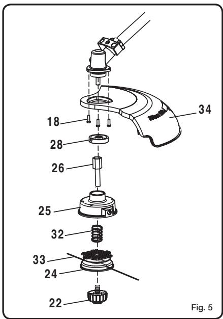
Follow these steps to attach the grass deflector (Fig. 5)
■ Attach the trimmer guard to the gear case.
■ Install three screws (18) through the guard and into to gear case.
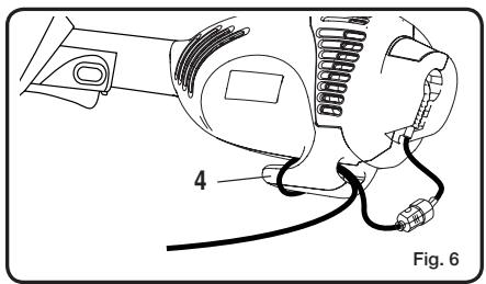
EXTENSION CORD RETAINER (FIG.6)
An extension cord retainer (4) is located on the bottom of the trimmer. This provides strain relief for the cord, preventing unwanted disconnects.
■ Use the extension cord retainer when you connect the extension cord to the power cord to prevent disconnection. Use only an outdoor approved extension cord.
■ Loop the extension cord through the extension cord retainer slot located on the bottom end of the trimmer.
■ Pull loop of extension cord around tongue and pull tight.
■ Attach extension cord to plug on trimmer.
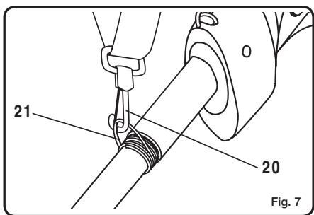
SHOULDER STRAP (FIG.7)
A shoulder strap (10) is supplied for your greater comfort.
■ Simply attach the clip (20) of the shoulder strap onto the hanger (21) at the front of the motor housing (5).
CONVERTING FROM STRING TRIMMER TO BRUSHCUTTER (FIG.4 & FIG.5)
REMOVING THE STRING HEAD
■ Align the slot in the upper flange washer (28) with the hole in the gear head (27). Place a holding pin through the slot in the upper flange washer and the hole in the gear head. Turn the bump knob (22) clockwise to remove. Remove the spool (24) and trimmer head (25) from the drive connector (26).
■ Place the holding pin through the upper flange washer and the gear head. Using a 17 mm wrench, turn the drive connector clockwise to remove.
■ Remove the upper flange washer from the gear shaft and retain for blade installation.
■ Remove the grass deflector.
Note: Store the string head parts together for later use.
INSTALLING THE BLADE
■ Place the upper flange washer over the gear shaft with the hollow side towards the blade guard.
- Centre the blade on the upper flange, making sure the blade sits flat. Install the cupped washer (29) with the raised centre away from the blade. Install the blade nut (30). The blade (12) turns counterclockwise from the operator's position.
■ Place the holding pin through the slot in the upper flange washer and the hole in the gear head (27). Using a 17 mm wrench, turn the blade nut counterclockwise.
■ Tighten nut securely.
■ Install the blade guard.
CONVERTING FROM BRUSHCUTTER TO STRING TRIMMER
REMOVING THE BLADE
■ Place the holding pin through the slot in the upper flange washer and the gear head. Turn the blade nut clockwise to remove.
■ Remove the cupped washer and the blade.
■ Remove the upper flange washer from the gear shaft and retain for the string head installation.
■ Remove the blade guard.
Note: Store the brushcutter parts together for later use.
INSTALLING THE STRING HEAD
■ Install the upper flange washer onto the gear shaft with the hollow side towards the gear head.
- Place the holding pin through the slot in the upper flange washer and the hole in the gear head. Using a 17 mm wrench, turn the drive connector anticlockwise to install. Tighten securely.
■ Place the trimmer head on the drive connector.
■ Place the holding pin through the slot in the upper flange washer and the hole in the gear head. Install the bump knob and turn anticlockwise to tighten securely.
■ Install the grass trimmer guard.
English
OPERATION

WARNING
The product may throw objects during operation, causing injury to the operator or to bystanders. Always wear suitable eye protection, boots, gloves and long, heavy trousers while operating the product.
STARTING AND STOPPING (FIG.8)
■ To start the tool: press the lock button (3) and then press the trigger (2). Release the lock button once the motor has started.
■ To stop the tool: Release the trigger.
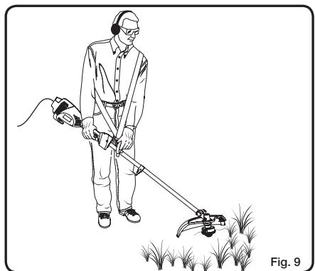
OPERATING THE TRIMMER (FIG.9)
Follow these steps to operate the trimmer.
- Plug the trimmer cord into an extension cord approved for outdoor use. Refer to “Electrical Safety Rules” earlier in this manual. If your unit is supplied with a 12M cable then an extension cable may not be necessary.
■ Once the unit is connected to electric power, the LiveTool Indicator (7) will show a blue light.
■ Put the shoulder strap (10) over your shoulder opposite side to the unit. Adjust shoulder strap to most comfortable length.
■ Hold the trimmer with your right hand on the trigger handle and your left hand on the front handle.
Note: Keep a firm grip with both hands during operation.
■ Place the trimmer on the side of your body with the motor behind and away from your body.
■ Press the lock button and then the trigger to start the trimmer.
■ The trimmer will build up speed steadily.
- Trim grass and weeds in a right-to-left motion with the line parallel to the ground.
Note: If the machine is overloaded, thermal protection inside the unit will cut off the trimmer. Leave the trimmer for about 10 minutes before turning it ON again. The lawn trimmer should then start.
■ To switch off the line trimmer, simply release the trigger.

WARNING
After switching off, the cutting element will continue to rotate for a few more seconds. Maintain vigilance until the line completely stops.
CUTTING TIPS
- Inspect and clear the area to be trimmed for any rocks, broken glass or wire that could be thrown or become entangled in the cutting line. Trim only when grass or weeds are dry. Keep the cutting line parallel to the ground.
- Cut grass or weeds over 20cm tall from the top to the bottom in small amounts. This will prevent grass becoming wrapped around the trimmer head assembly, which may result in damage due to overheating. If grass becomes wrapped around the trimmer head assembly, stop the trimmer, unplug it and remove the grass.
■ Move the trimmer slowly in and out of the area you are cutting, keeping the trimmer at the desired cutting height.
■ Use the tip of the line to do the cutting. Do not force the trimmer head assembly into uncut grass.
■ Feed out some line after each use to prevent the line from retracting into the cutting head.
■ The tip of the cutting line will wear during use; this reduces the cutting swath. If the line is not advanced occasionally, it will wear down to the eyelet. When the trimmer stops, the line tends to relax and may retract into the trimmer head assembly. Should this occur, unplug the trimmer, remove the spool, refeed the line through the eyelets and reassemble the spool.
■ Avoid hitting objects with the line, such as chain-link fences or concrete, as this causes rapid wear.
■ Never drag the trimmer head assembly on the ground while trimming.
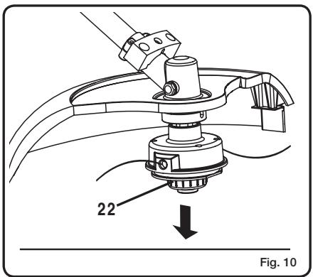
ADVANCING THE CUTTING LINE (FIG.10)
The trimmer includes the EZ LineTM Tap Advance System. Follow these steps to advance the cutting line automatically.
■ Tap the bump knob (22) lightly on the ground while the motor is running. Do not hold the bump knob on the ground.
Note: The line cutting off blade (23) on the safety guard will cut the line to the proper length.
Note: To help prevent line tangle, tap only once to lengthen the line. If additional line is required, wait a few seconds before retapping the bump knob. Keep the line length at or near full cutting diameter.
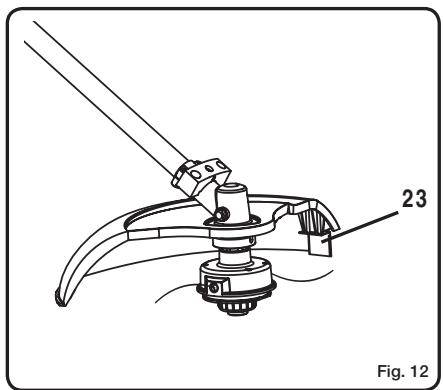
GRASS DEFLECTOR LINE TRIMMING CUT-OFF BLADE (FIG.12)
This trimmer is equipped with a line trimming cut-off blade (23) on the grass deflector. For best cutting, advance line until it is trimmed to length by the cut-off blade.
English
OPERATION
Advance line whenever you hear the engine running faster than normal. This will maintain best performance and keep line long enough to advance properly.
OPERATING THE BRUSHCUTTER (FIG. 11)
Hold the brushcutter with the right hand on the trigger handle and the left hand on the front handle. Keep a firm grip with both hands while in operation. Brushcutter should be held at a comfortable position with the trigger handle about hip height. Maintain your grip and balance on both feet. Position yourself so that you will not be drawn off balance by the kick-back reaction of the cutting blade.
Adjust the shoulder strap to position the brushcutter at a comfortable operating position and to assure that the shoulder strap will reduce the risk of operator contact with the blade.
Exercise extreme caution when using the blade with this unit. Blade thrust is the reaction which may occur when the spinning blade contacts anything it cannot cut. This contact may cause the blade to stop for an instant, and suddenly “thrust” the unit away from the object that was hit. This reaction can be violent enough to cause the operator to lose control of the unit. Blade thrust may occur without warning if the blade snags, stalls or binds. This is more likely to occur in areas where it is difficult to see the material being cut. For cutting ease and safety, approach the weeds being cut from the right to the left. In the event that an unexpected object or woody stock is encountered, this could minimise the blade thrust reaction.
TRI-ARC BLADE
The TRI-ARC blade is suited only for pulpy weeds and vines. When the blade becomes dull, it can be turned over to extend the life of the blade. Do not sharpen the TRI-ARC blade.
CUTTING TECHNIQUE - BLADE

WARNING
Extreme care must be taken when using blades to ensure safe operation. Read the safety information for safe operation using the blade, refer to “Specific Safety Rules for Brushcutter and Blade Use” earlier in this manual.
■ Always hold brushcutter with both hands when operating. Use a firm grip on both handles.
- Maintain your grip and balance on both feet. Position yourself so that you will not be drawn off balance by the kick-back reaction of the cutting blade.
■ Inspect and clear the area of any hidden objects such as glass, stones, concrete, fencing, wire, wood, metal, etc.
■ Never use blades near footpaths, fencing, posts, buildings or other immovable objects.
■ Never use a blade after hitting a hard object without first inspecting it for damage. Do not use if any damage is detected.
■ The unit is used as a scythe, cutting from the right to the left in a broad sweeping action from side to side.
MAINTENANCE

WARNING
Use only identical Ryobi replacement parts when servicing this product. Use of any other parts may create a hazard or cause product damage.
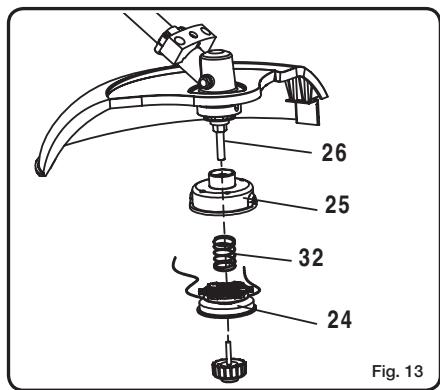
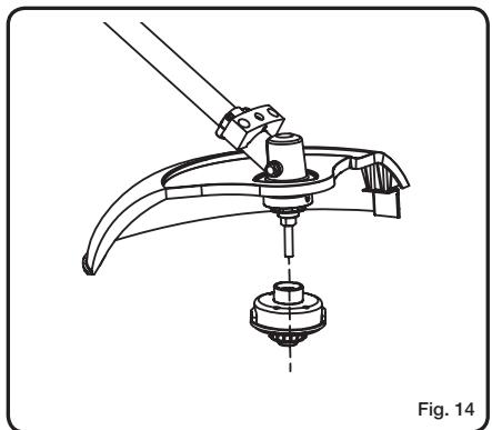
REPLACING THE CUTTING LINE AND SPOOL (FIG.13 & FIG.14)
When your cutting line wears out, replacement spools are available through our local retailer.
■ Release the trigger.
■ Unplug the trimmer.

WARNING
Make sure the trimmer head stops rotating. Contact with a rotating trimmer head could cause personal injury.
■ Remove the bump knob by turning it clockwise.
■ Remove the empty spool (24).
■ Clean the trimmer head (25) thoroughly. Inspect the trimmer head for any damaged or worn parts.
■ Hold the spool so that its tabbed side is positioned upward.
Note: On the new spool, the ends of the lines are secured in slots on tabs. Release the line from the tabs, unwind approximately 15cm of line and resecure the lines in the tabs.
- Insert the lines on the new spool into the eyelets in the trimmer head.
■ Place the spool on the drive connector (26).
Note: To install the spool, you may need to rotate it slightly.
Note: If the line should tangle or break at the eyelets, remove the spool, refeed the line through the eyelets and reassemble the spool on the trimmer.
■ Release the lines from the tabs by sharply pulling each line while pushing down on the spool.
■ Push down on the spool to reveal the drive shaft.
■ Place the bump knob on the drive shaft.
English
TROUBLESHOOTING
| PROBLEM | POSSIBLE CAUSE | SOLUTION |
| Line will not advance when tap bump button. | 1. Line is welded to itself.2. Not enough line on spool.3. Line is worn too short.4. Line is tangled on spool. | 1. Lubricate with a silicone spray.2. Install more line (Refer to “Replacing the Cutting Line” earlier in this manual).3. Pull lines while alternately pressing down on and releasing bump button.4. Remove line from spool and rewind (Refer to “Replacing the Cutting Line” earlier in this manual). |
| Bump head is hard to turn. | Grass wrapped or built up around head. | Clean affected parts of the machine. |
| Grass wraps around the attachment shaft and the trimmer head assembly. | Cutting tall grass at ground level. | Cut tall grass from the top down. |
| Unit stops and will not start again. | 1. Overload protection activated.2. Fuse from main supply blown.3. Unit failed. | 1. Wait 10 minutes before restarting.2. Check fuse.3. Contact dealer to check damage. |
DISPOSAL

natural_image
Symbol of a trash bin crossed out by two diagonal lines (no text or numbers present)
Waste electrical products should not be disposed of together with household waste. Please recycle where facilities exist. Check with your local authority or retailer for recycling advice.
Deutsch
natural_image
Symbol of a trash bin crossed out by two diagonal lines (no text or numbers present)
natural_image
Symbol of a trash bin crossed out by two diagonal lines (no text or numbers present)
natural_image
Symbol of a trash bin crossed out by two diagonal lines (no text or numbers present)
natural_image
Symbol of a trash bin crossed out by two diagonal lines (no text or numbers present)
MAAIDRAAD LATEN AFWIKKELEN (afb. 10)
natural_image
Symbol of a trash bin crossed out by a diagonal line, representing no waste or discharge (no text or labels present)
FÖRVARING OCH TRANSPORT
natural_image
Symbol of a trash bin crossed out by two diagonal lines (no text or numbers present)
FASTG∅RELSE AF TILBEH∅RETS SKAFT PÅ DET ∅VERSTE SKAFT (Fig. 2)
Sammenkoblingsmuffen (14) holder de to skafter sammen.
natural_image
Symbol of a trash bin crossed out by two diagonal lines (no text or numbers present)
FESTE TILBEH∅RETS SKAFT PÅ DET ∅VRE SKAFTET (Fig. 2)
RÅD FOR TRIMMING MED BLADET

ADVARSEL
natural_image
Symbol of a trash bin crossed out by two diagonal lines (no text or numbers present)
natural_image
Symbol of a trash bin crossed out by a diagonal line, representing no waste or discharge (no text or labels present)
natural_image
Symbol of a trash bin crossed out by two diagonal lines (no text or numbers present)
natural_image
Symbol of a trash bin crossed out by two diagonal lines (no text or numbers present)
NÜŽ NA ODŘÍZNUTÍ STRUNY NA OCHRANNÉM KRYTU (obr. 12)
natural_image
Symbol of a trash bin crossed out by two diagonal lines (no text or labels)
natural_image
Symbol of a trash bin crossed out by two diagonal lines (no text or numbers present)
CITIȚI TOATE INSTRUCTIUNILE.
natural_image
Symbol of a trash bin crossed out by two diagonal lines (no text or numbers present)
natural_image
Symbol of a trash bin crossed out by a diagonal line, representing no waste or discharge (no text or labels present)
natural_image
Symbol of a trash bin crossed out by two diagonal lines (no text or numbers present)
natural_image
Symbol of a trash bin crossed out by two diagonal lines (no text or numbers present)
natural_image
Symbol of a trash bin crossed out by two diagonal lines (no text or labels)
HOIDKE NEED JUHISED ALLES!
TEHNILISED OMADUSED
Pinge 230-240 V\~50 Hz
Nimivõimsus 1000 W
Tühikäigukiirus
natural_image
Symbol of a trash bin crossed out by two diagonal lines (no text or numbers present)
natural_image
Symbol of a trash bin crossed out by two diagonal lines (no text or numbers present)
natural_image
Symbol of a trash bin crossed out by two diagonal lines (no text or numbers present)
natural_image
Symbol of a trash bin crossed out by two diagonal lines (no text or numbers present)
natural_image
Symbol of a trash bin crossed out by two diagonal lines (no text or numbers present)
GARANTIE - CONDITIONS
All Ryobi products are guaranteed against manufacturing defects and defective parts for a period of twenty four (24) months from the date stated on the original invoice drawn up by the retailer and given to the end user. Deterioration caused by normal wear and tear, unauthorised or improper use or maintenance, or overload are excluded from this guarantee as are accessories such as battery packs, light bulbs, blades, fittings, bags, etc. In the event of malfunction during the warranty period, please take the NON-DISMANTLED product, along with the proof of purchase, to your retailer or nearest Authorised Ryobi Service Centre.
This warranty in no way affects your legal rights concerning defective products.
D
GARANTIE - BEDINGUNGEN
GARANTIJAS NOSACĪJUMI
According to machinery directive 98/37/EC, low voltage directive 2006/95/EC and EMC directive 89/336/EEC, we declare in sole responsibility that the product to which this certificate applies, conforms to the basic health and safety requirements of Directives 98/337/EC, 89/336/EEC, 93/68/EEC, 2006/95/EC and 2000/14/EC.
To effect correct application of the health and safety requirements stated in the EEC directives, the following European and/or national standards and/or technical speciations were consulted: EN60335-1:2002+A11:2004+A1:2004+A12:2006, EN60335-2-91:2003, EN786:1996+A1:2001, EN ISO 11806:1997, EN50366:2003+A1:2006, EN55014-1:2000/+A1:2001/+A2:2002, EN55014-2:1997/+A1:2001, EN61000-3-2:2000/+A2:2005, EN61000-3-3:1995/A1:2001+A2:2005
Brushcutter
| Measured sound power level: | 101.7 dB (A) |
| Guaranteed sound power level: | 103 dB (A) |
Grass trimmer
| Measured sound power level: | 95.3 dB (A) |
| Guaranteed sound power level: | 96 dB (A) |
| Date of issuance: | 01/2007 |
| Issued by: | Intertek ETL SEMKO Shanghai Ltd., RPC. |
Technical documents are kept by the Project Manager (Testing & Standards), Techtronic Appliances (HK) Ltd. 18/F/. CDW Building, 388 Castle Peak Road, Tsuen Wan, Hong Kong.
Intertek ETL SEMKO Shanghai Ltd., VRC.