DW 45 18.0-EC - Screwdriver Flex - Free user manual and instructions
Find the device manual for free DW 45 18.0-EC Flex in PDF.

| Brand | Flex |
| Model | DW 45 18.0-EC |
| Product type | Battery-powered drywall screwdriver |
| Battery | Lithium-ion 18V, 2.5 Ah or 5.0 Ah |
| No-load speed | 0-4500 min⁻¹ |
| Max torque (soft/hard) | 6 Nm / 28 Nm |
| Tool holder | 1/4" (6.35 mm) hexagon socket |
| Weight (without battery) | 0.98 kg |
| Weight battery 2.5 Ah | 0.42 kg |
| Weight battery 5.0 Ah | 0.72 kg |
| Screw magazine (length) | 273 mm |
| Screw magazine (weight) | 0.48 kg |
| Max screws per strip | 50 |
| Max screw length | 55 mm |
| Max screw shank diameter | 4.2 mm |
| Sound pressure level | 71 dB(A) |
| Sound power level | 82 dB(A) |
| Vibrations (screwing) | < 2.5 m/s² |
| Functions | Screwing, unscrewing, depth adjustment, lighting, operation with/without locking, reversible |
| Maintenance | Regular cleaning with dry compressed air |
| Safety | Insulated handles, workpiece securing, battery protection |
| Repairability | Approved service center, exploded views on www.flex-tools.com |
| Compliance | CE, EN 62841, directives 2004/108/EC, 2006/42/EC, 2011/65/EC |
Frequently Asked Questions - DW 45 18.0-EC Flex
User questions about DW 45 18.0-EC Flex
0 question about this device. Answer the ones you know or ask your own.
Ask a new question about this device
Download the instructions for your Screwdriver in PDF format for free! Find your manual DW 45 18.0-EC - Flex and take your electronic device back in hand. On this page are published all the documents necessary for the use of your device. DW 45 18.0-EC by Flex.
USER MANUAL DW 45 18.0-EC Flex
natural_image
Illustration of four different types of electrical drillers or power tools, arranged in a row (no text or symbols present)natural_image
Two hands performing a mechanical clamp or clamping operation, showing tool positioning and mounting details (no text or symbols present)
VORSICHT!
natural_image
Mechanical assembly diagram showing a spring being inserted into a housing component, with no visible text or symbols.natural_image
Mechanical assembly diagram showing a gun with internal components and a close-up of the gun's internal structure (no text or symbols present)natural_image
Cross-sectional diagram of a mechanical tool or device with internal components and motion arrows (no text or symbols)natural_image
Technical illustration of a firearm with screws inserted into the jaw (no text or symbols)natural_image
Illustration of a drill bit with screw and drill bit, showing tool path and motion arrows (no text or symbols)natural_image
Illustration of a screwdriver tool interacting with a mechanical component, showing internal components and assembly (no text or symbols)natural_image
Illustration of a robotic hand holding a device with an arrow indicating motion (no text or symbols present)natural_image
Close-up of a power drill with tool and directional arrow indicator (no text or symbols)natural_image
Close-up of a drill bit being inserted into a power tool, showing blade and tip (no text or symbols visible)natural_image
Four-panel illustration showing a hand operating a drill pen, with no visible text or symbols.Klaus Peter Weinper Head of Quality Department (QD)
Symbols used in this manual ..... 16
Symbols on the power tool 16
For your safety 16
Noise and vibration 18
Technical specifications 19
Overview 20
Instructions for use 22
Maintenance and care 27
Disposal information 27
Transport 27
C €-Declaration of Conformity ..... 28
Exemption from liability 28
Symbols used in this manual

WARNING!
Denotes impending danger. Non-observance of this warning may result in death or extremely severe injuries.

CAUTION!
Denotes a possibly dangerous situation. Non-observance of this warning may result in slight injury or damage to property.

NOTE
Denotes application tips and important information.
Symbols on the power tool

Before switching on the power tool, read the operating manual!
Short-circuit-proof safety transformer
Rechargeable lithium-ion battery
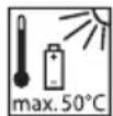
Protect the battery from heat, e.g. from continuous exposure to sunlight and fire.
There is a risk of explosion!
Do not throw battery in the fire. There is a risk of explosion!
Device is suitable for use indoors only. Do not expose the device to rain. Store electric power tool and batteries in dry rooms.
Leaking battery fluid may cause skin irritation or burns.
Disposal instructions (see page 27)
For your safety

WARNING!
Before using the power tool, please read and follow:
- these operating instructions,
- the "General safety instructions" on the handling of power tools in the enclosed booklet (leaflet-no.: 315.915),
- the currently valid site rules and the regulations for the prevention of accidents.
This power tool is state of the art and has been constructed in accordance with the acknowledged safety regulations.
Nevertheless, when in use, the power tool may be a danger to life and limb of the user or a third party, or the power tool or other property may be damaged.
The power tool may be operated only if it is
- as intended,
- in perfect working order.
Faults which impair safety must be eliminated immediately.
Intended use
The cordless dry wall screwdriver is DW 45 18.0-EC is designed
– for commercial use in industry and trade,
– for screwing drywalls, chipboard or fibreboard onto wood or metal using drywall screws,
– for screwing sheet metal or wood screws into interior fittings,
- to be used with suitable tools recommended by the manufacturer for this power tool.
The screw magazine M-DW is designed for the quick insertion of drilling screws, chipboard screws and wood construction screws.
The screw magazine may be used only in conjunction with the following battery dry wall screwdrivers:
- DW 45 18.0-EC
Safety instructions for cordless dry wall screwdrivers and screw magazines

WARNING!
Read all safety warnings and all instructions. Failure to follow the warnings and instructions may result in electric shock, fire and/or serious injury. Save all warnings and instructions for future reference.
■ Hold power tool by insulated gripping surfaces only, when performing an operation where the cutting accessory may contact hidden wiring.
Cutting accessory contacting a “live” wire may make exposed metal parts of the power tool “live” and shock the operator.
■ Hold the electric power tool securely. When tightening and loosening screws, high reaction torques may occur briefly.
- Secure the workpiece.
A workpiece is held more securely in a clamping device or vice than by hand.
■ Wait until the electric power tool has come to a standstill before putting it down. The insertion tool may jam and cause you to lose control of the electric power tool.
■ Wear suitable clothing. Do not wear any loose clothing or jewellery. Keep hair, clothing and gloves away from moving parts.
Loose clothing, jewellery or long hair may become caught in moving parts.
■ Do not point the electric power tool at yourself or at other people nearby.
■ While working, do not reach into the screw magazine or touch the area where screws are being inserted.
There is a risk of injury from crushing or sharp-edged screws.
■ Use only suitable screw belts according to the section "Technical Data".
If other screws are used, the screw magazine may be damaged.
Safety instructions for handling batteries
■ Do not open the battery.
There is a risk of a short-circuit.
■ Protect the battery from heat, e.g. from continuous exposure to sunlight, fire, water and humidity.
There is a risk of explosion.
■ A damaged or incorrectly used battery may result in the emission of fumes. Ensure a supply of fresh air and consult a doctor in the event of any physical complications. The fumes may irritate the respiratory tracts.
- Liquid may leak out of the battery if the battery is incorrectly used. Avoid contact with such liquid. If contact accidentally occurs, rinse with water. If liquid contacts eyes, seek medical attention. Liquid leaking from the battery may cause irritation or burns.
■ Recharge batteries only with chargers recommended by the manufacturer.
A charger that is suitable for one type of battery may create a fire hazard when used with another battery.
■ The battery may be damaged by pointed objects such as e.g. nails or screwdrivers or by external application of force. This may give rise to an internal short circuit, causing the battery to burn, smoke, explode or overheat.
Special safety instructions
Identify the power tool with stickers only.
Do not drill any holes into the housing.
Noise and vibration
The noise and vibration values have been determined in accordance with EN 62841.
The A evaluated noise level of the power tool is typically:
- Sound pressure level L_pA : 71 dB(A);
- Sound power level L_WA : 82 dB(A);
– Uncertainty K: 3 dB.
otal vibration value (when fixing screws):
– Emission value a_h : <2.5 m/s
– Uncertainty K: 1.5 m/s ^2

CAUTION!
The indicated measurements refer to new power tools. Daily use causes the noise and vibration values to change.

NOTE
The vibration emission level given in this information sheet has been measured in accordance with a standardised test given in EN 62841 and may be used to compare one tool with another. It may be used for a preliminary assessment of exposure. The declared vibration emission level represents the main applications of the tool. However if the tool is used for different applications, with different accessories or poorly maintained, the vibration emission may differ. This may significantly increase the exposure level over the total working period. For a precise estimation of the vibration load the times should also be considered during which the power tool is switched off or even running, but not actually in use.
This may significantly decrease the exposure level over the total working period. Identify additional safety measures to protect the operator from the effects of vibration such as: maintain the tool and the accessories, keep the hands warm, organisation of work patterns.

CAUTION!
Wear ear protection at a sound pressure above 85 dB(A).
Technical specifications
| DW 45 18.0-EC | ||
| Machine type Cordless dry wall screwdriver | ||
| Battery Ah | AP 18.0/2.5AP 18.0/5.0 | |
| No load speed | min^-1 | 0-4500 |
| Max. drill diameter Nm (Soft/Hard) 6/28 | ||
| Tool holder | 1/4" (6.35 mm)hexagon socket | |
| Weight according to “EPTA procedure 01/2003”(without battery) | kg 0.98 | |
| Weight battery– AP 18.0/2.5– AP 18.0/5.0 | kgkg | 0.420.72 |
| Screw magazine | ||
| Length mm | 273 | |
| Weight, without screw belt kg 0.48 | ||
| Screws per belt (max.) | 50 | |
| Screw size– Length– Max. shank diameter | mmmm | 554.2 |
Overview
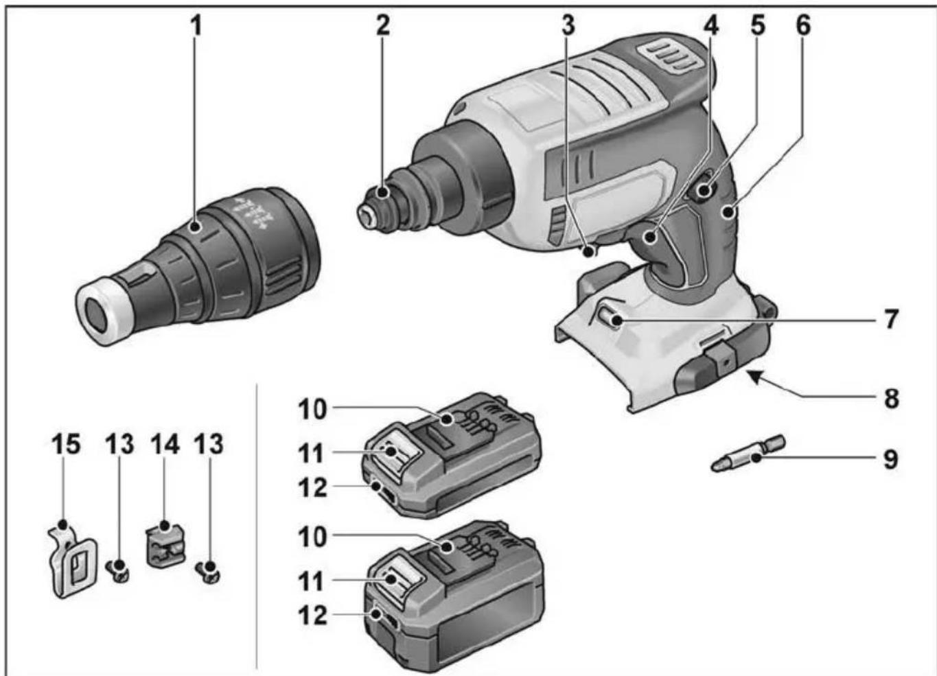
1 Stop sleeve
2 C l u t c h
3 Lever for selecting direction of rotation (Clockwise/anti-clockwise)
4 ON/OFF switch with accelerator function
5 Locking button
6 Handle
7 Work light
8 Insertion slot for battery
9 Screwdriver bit
10 Li-ion battery (2.5 Ah or 5.0 Ah)
11 Release button for battery
12 State of charge indicator
13 Fastening screw
14 Bit bracket
15 Belt clip
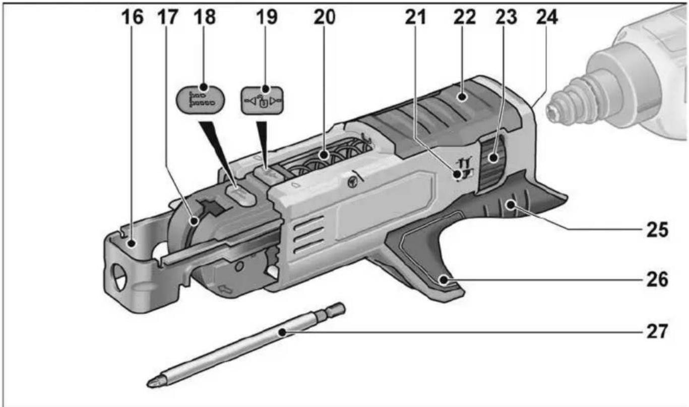
16 Depth stop
17 Guide rail for screw belt
18 Locking button for screw length
19 Lock button
20 Spring
21 Display for screw-in depth
22 Housing
23 Dial for screw-in depth
24 Holder
25 Handle
26 Guide shaft for screw belt
27 Screwdriver bit
Instructions for use

WARNING!
Remove the battery before carrying out any work on the power tool.
Before switching on the power tool
■ Unpack power tool and accessories and check that no parts are missing or damaged.
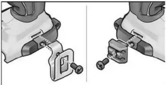
■ Attach the belt clip and bit holder with the enclosed fastening screw.
natural_image
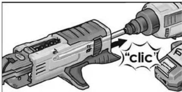
Two hands performing a mechanical clamp or clamping operation, showing tool positioning and mounting details (no text or symbols visible)Inserting/replacing the battery
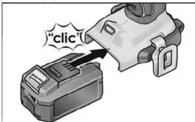
■ Press the charged battery into the power tool until it clicks into place.
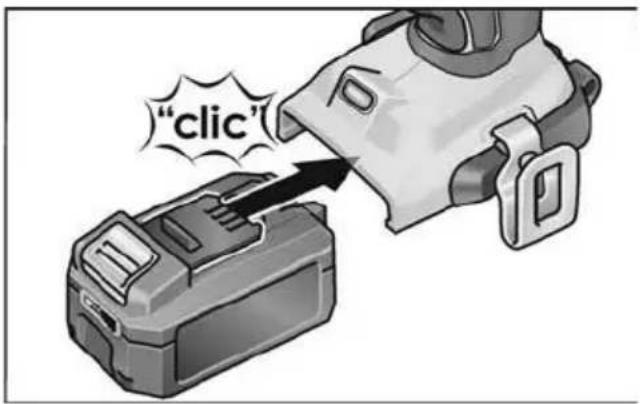
■ To remove, press the release button (1.) and pull out the battery (2.).
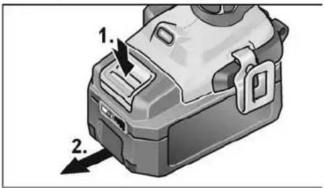

CAUTION!
Protect the battery contacts when the battery is not being used. Loose metal parts may short-circuit the contacts – Explosion and fire hazard!
Battery state of charge
■ Press the button to check the state of charge at the state of charge indicator LEDs.
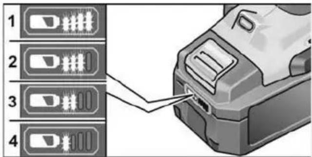
If one of the LEDs flashes, the battery must be recharged. If none of the LEDs light up after the button is pressed, the battery is faulty and must be replaced.
The indicator goes out after 5 seconds.

NOTE
Follow the instructions for charging the battery in the operating instructions for the electric power tool and the battery charger.
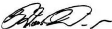
Inserting the tools
Screwdriver bit

WARNING!
Remove the battery before carrying out any work on the power tool.

CAUTION!
Before performing any work on the electric power tool, move the lever for selecting direction of rotation (3) to the middle position.
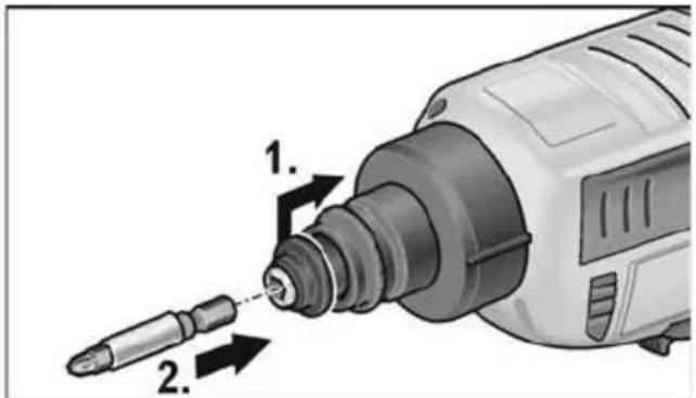
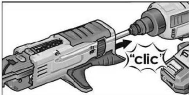
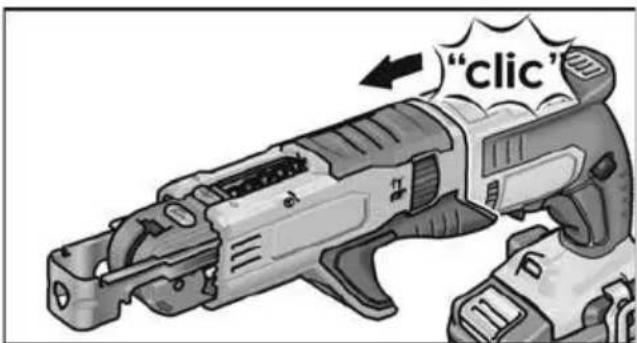
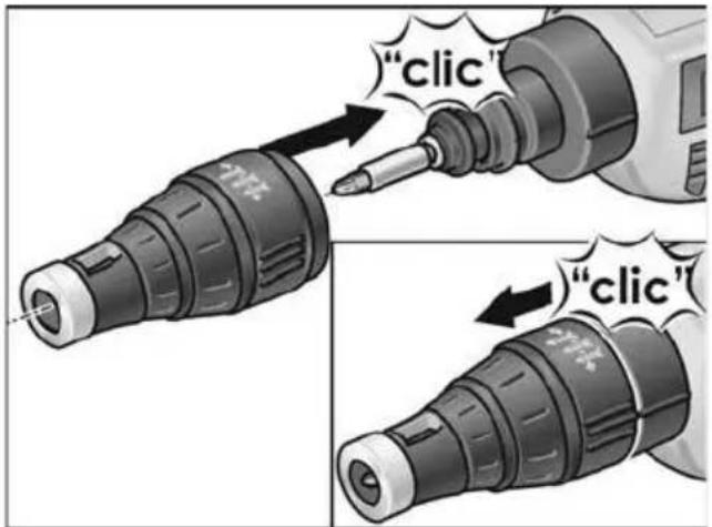
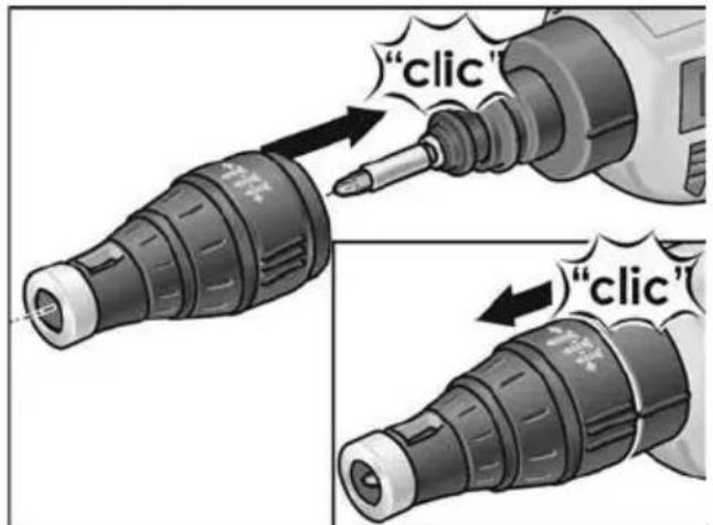
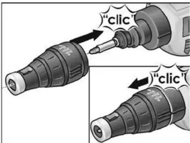
■ Push coupling towards rear (1.).
■ Insert screwdriver bit into the bit holder (2.).
■ Release coupling.
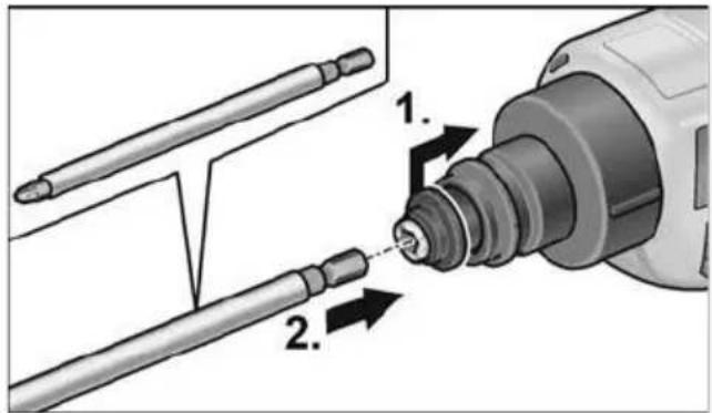
Stop sleeve

■ Attach stop sleeve to drywall screwdriver.
■ Remove stop sleeve from drywall screwdriver.
i NOTE!
The stop sleeve is not required to loosen screws.
Screw magazine
WARNING!
Remove the battery before carrying out any work on the power tool.
CAUTION!
Before performing any work on the electric power tool, move the lever for selecting direction of rotation (3) to the middle position.
■ Push coupling towards rear (1.).
■ Insert screwdriver bit into the bit holder (2.).
■ Release coupling.
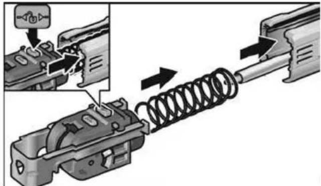
Attach the screw magazine:
natural_image
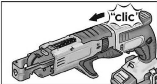
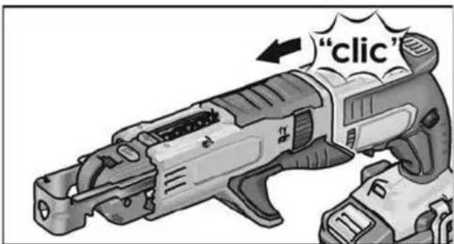
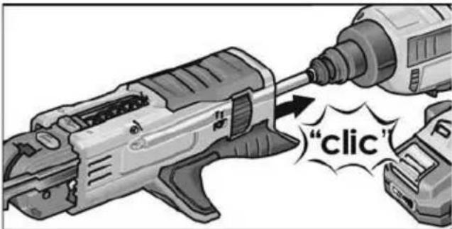
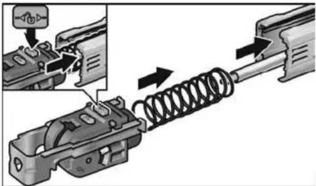
Mechanical assembly diagram showing a spring being inserted into a housing component, with an inset close-up of the component (no text or symbols present)■ Press lock button and insert carriage into guide.

■ Attach screw magazine to drywall screwdriver.
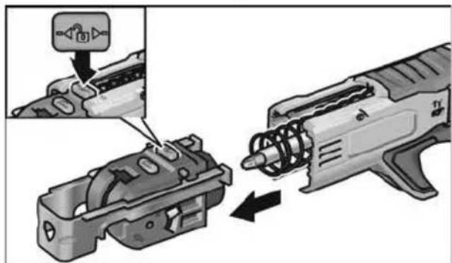
Remove the screw magazine:
natural_image
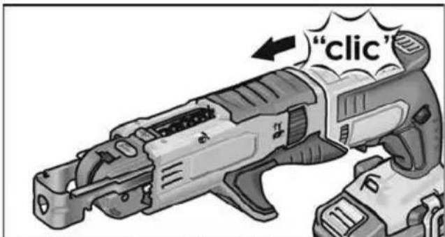
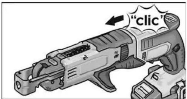
Illustration of a firearm being inserted into a component, showing internal components and motion direction (no text or symbols)■ Press lock button and pull out carriage.
■ Remove screw magazine from drywall screwdriver.
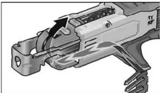
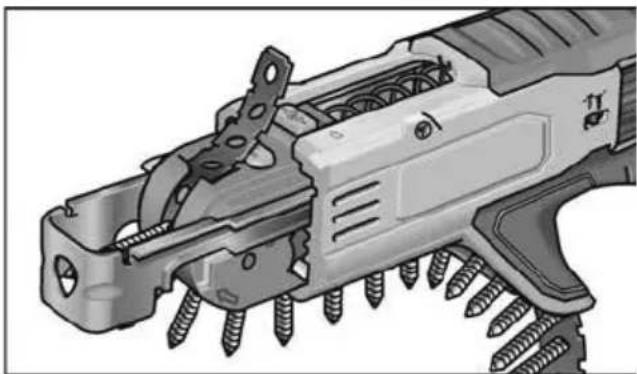
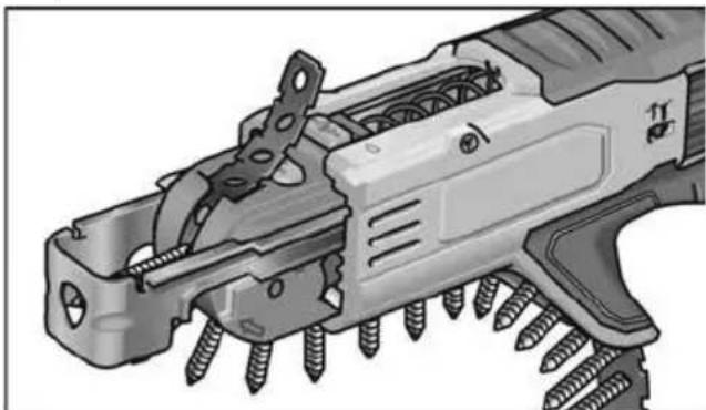
Insert screw belt
natural_image
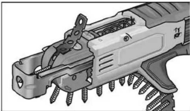
Technical illustration of a mechanical tool with internal components and motion arrows (no text or symbols)■ Insert screw belt from underneath.
natural_image
Technical illustration of a mechanical device with screws and internal components (no text or symbols)Changing screw-in depth Stop sleeve

CAUTION!
Before performing any work on the electric power tool, move the lever for selecting direction of rotation (3) to the middle position.
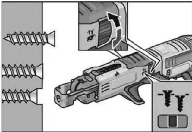
■ Change screw-in depth by turning the stop sleeve for the screw depth stop.
- Turn clockwise: Screw-in depth increases
- Turn anti-clockwise: Screw-in depth decreases

natural_image
Diagram showing screw installation process with a drill bit and tool, no text or symbols presentOne notch (45°) on the adjusting sleeve corresponds to a change in the screw-in depth of 0.2 mm.
One complete rotation (360°) of the adjusting sleeve therefore corresponds to a change in the screw-in depth of 1.6 mm.

NOTE!
Start with a fairly low screw-in depth to prevent damaging the workpieces which are to be screwed in place.
Screw magazine

CAUTION!
Before performing any work on the electric power tool, move the lever for selecting direction of rotation (3) to the middle position.
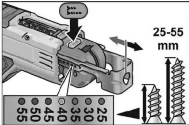
■ Press setting button and adjust screw length manually.
natural_image
Illustration of a screwdriver being inserted into a tool, showing mechanical components and assembly (no text or symbols)■ Turn dial to adjust screw-in depth.
Setting direction of rotation

CAUTION!
Do not change direction of rotation until the power tool is at a standstill.
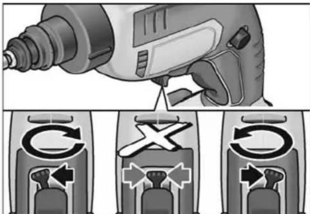
■ Set switch for selecting direction of rotation to the required position:
- Left: counter-clockwise (loosening screws)
- Right: clockwise (inserting screws)
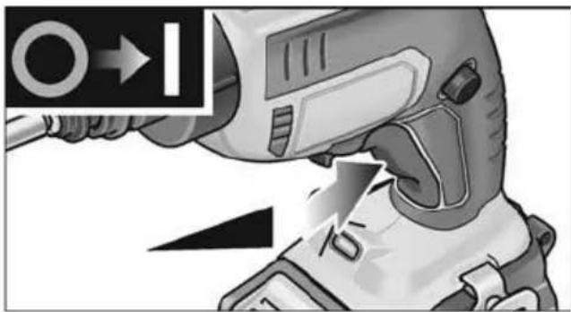
Switching on the power tool Switching on without locking
natural_image
Illustration of a robotic hand holding a device with an arrow indicating motion (no text or symbols present)■ Press and hold down the switch. The electric power tool switch enables the speed to be increased slowly to the maximum value.
Switching off the electric power tool:
■ Release the switch.
Switching on with locking
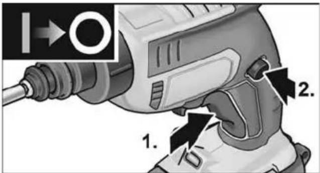
- Press and hold down the switch (1.). - Press locking button to lock the switch (2.).
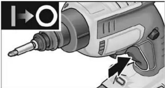
Switching off the electric power tool:
natural_image
Close-up of a power drill with a tool and directional arrow indicator (no text or symbols)■ Press and release the switch.
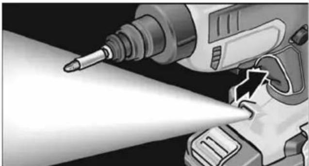
Work light
natural_image
Illustration of a drill presser using a tool to lift a light bulb (no text or symbols visible)■ Press switch to activate and deactivate.
Operating instructions

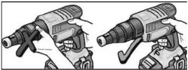
CAUTION!
Do not grip the rotating screwdriver head.
Stop sleeve
Screwing in screws:
natural_image
Illustration of two hands operating a drill press, showing tool positioning and adjustment (no text or symbols)
natural_image
Illustration of two hands using a drill press to adjust the drill (no text or symbols present)- Insert appropriate screwdriver bit.
- Set screw-in depth.
- Set direction of rotation (clockwise).
- Grip electric power tool with one hand on the handle and assume working position.
- Place screw on the screwdriver bit. The screw is held by magnetic force.
- Press screw tip against the workpiece to be screwed in place until the stop sleeve is positioned on the workpiece. Hold electric power tool at right angles to the surface of the workpiece!
- Switch on the power tool. The screw is screwed into the workpiece until the set screw-in depth is reached. Check screw-in depth, change if required.

NOTE!
When the preset screw-in depth is reached, the drive is disengaged, the screwdriver bit stops turning.
- When you have finished fixing screws, switch off the electric power tool.
At the end of work:
- Move the direction of rotation selector (3) to the middle position.
Loosening screws:
- Insert appropriate screwdriver bit.
- Set direction of rotation (anti-clockwise).
- Grip electric power tool with one hand on the handle and assume working position.
- Place screwdriver bit on the screw to be loosened.
-
Switch on electric power tool by pressing the switch. The screw is loosened.
-
After unscrewing the screw, release the switch.
At the end of work:
- Move the direction of rotation selector (3) to the middle position.
Screw magazine
Screwing in screws:
- Inserting screw blet.
- Set screw-in depth.
- Set direction of rotation (clockwise).
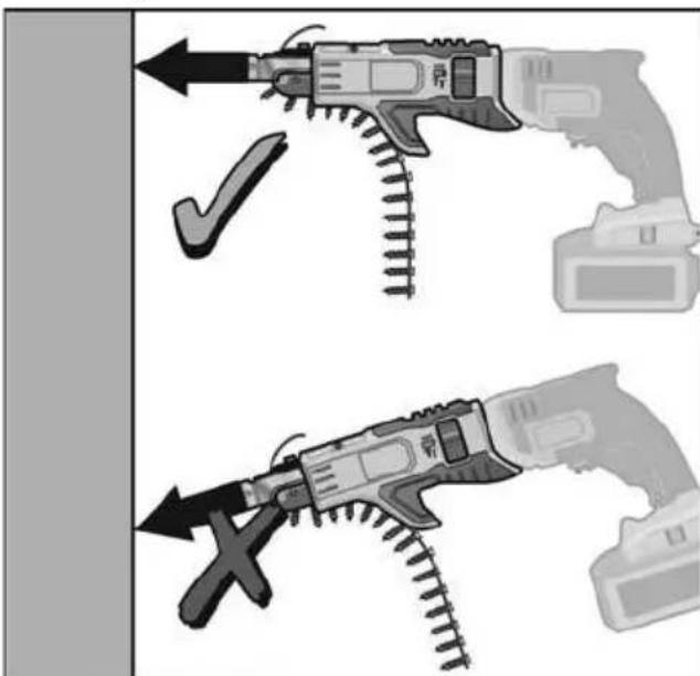
- Grip electric power tool with both hands on the handle and assume working position.
-
Press depth stop (for screw length) against workpiece to be screwed in place. Hold power tool at right angles to workpiece surface!
-
Switch on the power tool.
The screw is screwed into the workpiece until the set screw-in depth is reached.
Check screw-in depth, change if required.

NOTE!
When the preset screw-in depth is reached, the drive is disengaged, the screwdriver bit stops turning
- When you have finished fixing screws, switch off the electric power tool.
At the end of work:
- Move the direction of rotation selector (3) to the middle position.
Maintenance and care

WARNING!
Remove the battery before carrying out any work on the power tool.

CAUTION!
Before performing any work on the electric power tool, move the lever for selecting direction of rotation (3) to the middle position.
Cleaning

CAUTION!
When cleaning with compressed air, always wear goggles.
■ Regularly clean the power tool and ventilation slots. Frequency of cleaning is dependent on the material and duration of use.
■ Regularly blow out the housing interior and motor with dry compressed air.
■ Regularly blow out screw magazine with dry compressed air.
Repairs
Repairs may be carried out by an authorised customer service centre only.
Spare parts and accessories
For other accessories, in particular tools and polishing aids, see the manufacturer's catalogues.
Exploded drawings and spare-part lists can be found on our homepage:
www.flex-tools.com
Disposal information

WARNING!
Render redundant power tools unusable:
- mains operated power tool by removing the power cord,
- battery operated power tool by removing the battery.

EU countries only
Do not throw electric power tools into the household waste! In accordance with the European Directive 2012/19/EU on Waste Electrical and Electronic Equipment and transposition into national law used electric power tools must be collected separately and recycled in an environmentally friendly manner.

Raw material recovery instead of waste disposal.
Device, accessories and packaging should be recycled in an environmentally friendly manner. Plastic parts are identified for recycling according to material type.

WARNING!
Do not throw batteries into the household waste, fire or water. Do not open used batteries.
EU countries only:
In accordance with Directive 2006/66/EC defective or used batteries must be recycled.

NOTE
Please ask your dealer about disposal options!
Transport
The equivalent lithium content of the batteries included in the product package is below the appropriate limit values.
Therefore the battery as an individual component as well as the power tool and its product package are not subject to national or international dangerous goods regulations. If several machines with lithium ion batteries are transported, these regulations may become relevant and special safety measures may be required (e.g. for the packaging).
In this case find out about the currently valid regulations for the country of use.
CE-Declaration of Conformity
We declare under our sole responsibility that the product described under “Technical specifications” conforms to the following standards or normative documents:
EN 62841 in accordance with the regulations of the directives 2014/30/EU, 2006/42/EC, 2011/65/EU.
Responsible for technical documents:
Eckhard Rühle
Manager Research &
Development (R & D)
Klaus Peter Weinper
Head of Quality
Department (QD)
17.12.2018
Exemption from liability
The manufacturer and his representative are not liable for any damage and lost profit due to interruption in business caused by the product or by an unusable product.
The manufacturer and his representative are not liable for any damage which was caused by improper use of the power tool or by use of the power tool with products from other manufacturers.
Table des matières
Batterie lithium-ions rechargeable
Li-Ion
natural_image
Two hands performing a mechanical clamp or clamping operation, showing tool positioning and mounting details (no text or symbols visible)
PRUDENCE!
natural_image
Mechanical assembly diagram showing a spring-loaded component being inserted into a housing (no text or symbols visible)natural_image
Mechanical assembly diagram showing a gun with internal components and a close-up of the gun's internal structure (no text or symbols present)natural_image
Technical illustration of a mechanical tool with internal components and motion arrows (no text or symbols)natural_image
Technical illustration of a firearm with screws inserted into the jaw (no text or symbols)natural_image
Illustration of a screwdriver tip fastening a screw, showing mechanical components and motion arrows (no text or symbols)natural_image
Illustration of a hairpin being inserted into a screwdriver, showing mechanical components and tool positioning (no text or symbols)natural_image
Illustration of a robotic hand holding a device with an arrow indicating motion (no text or symbols present)natural_image
Close-up of a power tool with a screwdriver and a circular indicator symbol (no readable text or symbols)natural_image
Illustration of a power tool with a pointed tip and a tool inserted into a device (no text or symbols visible)natural_image
Four-panel illustration showing hands using a drill press to adjust the drill (no text or symbols present)Eckhard Rühle
Manager Research & Development (R & D)
Klaus Peter Weinper
Head of Quality Department (QD)
17.12.2018
natural_image
Two hands performing a mechanical clamp or clamping operation, showing tool positioning and mounting details (no text or symbols visible)natural_image
Mechanical assembly diagram showing a spring-loaded component being inserted into a housing (no text or symbols visible)natural_image
Mechanical assembly diagram showing a gun with internal components and a close-up of the gun's handle (no text or symbols present)natural_image
Cross-sectional diagram of a mechanical tool or device with internal components and motion arrows (no text or symbols)natural_image
Technical illustration of a firearm with screws inserted into the jaw (no text or symbols)natural_image
Illustration of a screwdriver tool interacting with a mechanical component, showing motion arrows (no text or symbols)natural_image
Illustration of a hairbrush tool being inserted into a screwdriver, showing mechanical components and tool path (no text or symbols)natural_image
Illustration of a robotic hand holding a device with an arrow indicating motion (no text or symbols present)natural_image
Close-up of a power drill with a tool and directional arrow indicator (no text or symbols)natural_image
Illustration of a drill presser operating a tool with a pointed tip (no text or symbols visible)natural_image
Illustration of two hands operating a portable device with a tool, showing motion and assembly (no text or symbols)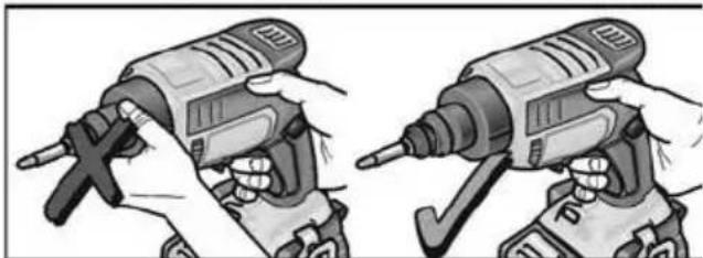
natural_image
Illustration of two hands using a drill press to adjust the tool (no text or symbols visible)Manager Research & Development (R & D)
Klaus Peter Weinper
Head of Quality Department (QD)
17.12.2018
1 Manguito tope
2 Acoplamiento
natural_image
Two hands performing a mechanical clamp or bracketing operation, showing pin alignment and mounting details (no text or symbols present)natural_image
Illustration of a drill bit with two labeled parts (1 and 2), showing the drill bit being inserted into a tool (no text or symbols present)natural_image
Mechanical assembly diagram showing a spring-loaded component being inserted into a housing (no text or symbols visible)natural_image
Mechanical assembly diagram showing a gun firing into a housing component, with an inset close-up of the tool (no text or symbols present)natural_image
Technical illustration of a mechanical tool with internal components and motion arrows (no text or symbols)natural_image
Cross-sectional diagram of a firearm showing internal components and screws (no text or labels)natural_image
Illustration of a drill bit being inserted into a screw, showing tool path and motion arrows (no text or symbols)natural_image
Illustration of a screwdriver and its internal components, showing assembly and disassembly (no text or symbols)natural_image
Illustration of a robotic hand holding a device with an arrow indicating motion (no text or symbols present)natural_image
Close-up of a power drill with a tool and directional arrow indicator (no text or symbols)natural_image
Illustration of a power tool with a pointed tip and light beam, showing mechanical components (no text or symbols)natural_image
Illustration of two hands operating a drill pen, showing motion and tool positioning (no text or symbols)
natural_image
Illustration of two hands using a drill press to adjust the drill (no text or symbols present)Manager Research & Development (R & D)
Klaus Peter Weinper
Head of Quality
Department (QD)
17.12.2018
natural_image
Two-step illustration of hands using a clamp or bracket to adjust a mechanical component (no text or symbols present)Aplicar/substituir o acumulador
■ Encaixar o casquilho de batente na aparafusadora de pladur.
■ Retirar o casquilho de batente da aparafusadora de pladur.
i INDICAÇÃO
natural_image
Mechanical assembly diagram showing a spring being inserted into a housing component, with an inset close-up of the component (no text or symbols visible)natural_image
Technical illustration of a mechanical tool with internal components and motion arrows (no text or symbols)natural_image
Technical illustration of a mechanical tool with screws and internal components (no text or symbols)natural_image
Illustration of a screwdriver tip fastening a screw, showing mechanical components and motion arrows (no text or symbols)natural_image
Illustration of a hairpin being inserted into a screwdriver, showing mechanical components and tool path (no text or symbols)■ Rodar a roda de ajuste para ajustar a profundidade de aparafusamento.
natural_image
Illustration of a robotic hand holding a device with directional arrows indicating movement (no text or symbols)natural_image
Close-up of a power tool with a screwdriver and a magnified view showing the blade (no text or symbols visible)■ Premir e libertar o interruptor.
natural_image
Illustration of a drill presser operating a tool with a pointed tip and focused on the blade (no text or symbols visible)natural_image
Four-panel illustration showing hands using a drill press to adjust the drill (no text or symbols present)Eckhard Rühle Manager Research & Development (R & D)
Klaus Peter Weinper Head of Quality Department (QD)
17.12.2018
natural_image
Two hands performing a mechanical clamp or clamping operation, showing tool positioning and mounting details (no text or symbols visible)natural_image
Illustration of a drill bit with two labeled parts (1 and 2), showing the drill bit being inserted into a tool (no text or symbols present)natural_image
Mechanical assembly diagram showing a spring being inserted into a housing component, with an inset close-up of the component (no text or symbols present)■ Vergrendelingsknop indrukken en de slede in de geleider schuiven.
natural_image
Diagram showing a gun assembly process with a magnified inset of the component (no text or symbols present)■ Vergrendelingsknop indrukken en de slede eruit trekken.
natural_image
Technical illustration of a mechanical device with internal components and motion arrows (no text or symbols)natural_image
Technical illustration of a firearm with screws inserted into the jaw (no text or symbols)natural_image
Illustration of a drill bit with screw and drill bit removed, showing tool path and motion arrows (no text or symbols)natural_image
Illustration of a hairpin being inserted into a screwdriver, showing mechanical components and tool path (no text or symbols)natural_image
Illustration of a robotic hand holding a device with an arrow indicating motion (no text or symbols present)natural_image
Close-up of a power drill with a tool and directional arrow indicator (no text or symbols)natural_image
Illustration of a power tool with a drill bit and tool handle, no text or symbols presentnatural_image
Four-panel illustration showing a hand using a drill pen to adjust the tool, no text or symbols present.Eckhard Rühle
Manager Research & Development (R & D)
Klaus Peter Weinper
Head of Quality
Department (QD)
17.12.2018
natural_image
Two hands operating a mechanical clamp or bracket device, showing alignment and mounting details (no text or symbols visible)■ Tryk koblingen bagud (1.).
■ Sæt skruebitten i bitholderen (2.).
■ Slip koblingen.
Anslagsbøsning
■ Tryk koblingen bagud (1.).
■ Sæt skruebitten i bitholderen (2.).
■ Slip koblingen.
natural_image
Mechanical assembly diagram showing a spring-loaded component being inserted into a housing (no text or symbols visible)natural_image
Illustration of a firearm being inserted into a housing, showing internal components and motion direction (no text or symbols)natural_image
Cross-sectional diagram of a firearm showing internal components and airflow direction (no text or labels)natural_image
Technical illustration of a mechanical device with screws and internal components (no text or symbols)natural_image
Illustration of a drill bit being inserted into a screw, showing tool path and motion arrows (no text or symbols)natural_image
Illustration of a screwdriver and tool assembly with no visible text or symbolsnatural_image
Illustration of a robotic hand holding a device with directional arrows indicating motion (no text or symbols)natural_image
Close-up of a power drill with a tool and directional arrow indicator (no text or symbols)natural_image
Illustration of a drill presser operating a tool with a pointed tip, showing motion blur and no text or symbols.natural_image
Illustration of two hands operating a drill press, showing mechanical components and tool positioning (no text or symbols)
natural_image
Illustration of two hands using a drill press to lift a tool, showing mechanical components (no text or symbols)Klaus Peter Weinper Head of Quality Department (QD)
natural_image
Two mechanical clamping or bracketing setups showing metal components and screws (no text or symbols visible)Sette inn/skifte batteri
FORSIKTIG!
natural_image
Illustration of a drill bit with two labeled parts (1 and 2), showing the drill bit being inserted into a tool (no text or symbols present)■ Trykk koblingen bakover (1.).
■ Sett skrubits inn i bitopptaket (2.).
■ Slipp koblingen.
Anslagshylse
■ Sett stopphylsen på gipsskutrekkeren.
■ Trekk stopphylsen fra gipsskrutrekkeren.
i HENVISNING
For løsning av skruene trenges ikke anslags-hylsen.
Skruemagasin
ADVARSEL!
■ Trykk koblingen bakover (1.).
■ Sett skrubits inn i bitopptaket (2.).
■ Slipp koblingen.
■ Trykk på låseknappen, og sett glidestykket i føringen.

■ Sett skruemagasinet på gipsskrutrekkeren.
Demontere skruemagasinet:

natural_image
Mechanical assembly diagram showing a gun with internal components and a close-up of the gun's handle (no text or symbols present)natural_image
Cross-sectional diagram of a mechanical tool or device with internal components and motion arrows (no text or symbols)natural_image
Cross-sectional diagram of a firearm showing internal components and screws (no text or labels)natural_image
Illustration of a screwdriver tip fastening a screw, showing tool movement and component placement (no text or symbols)En sprekk (45°) på innstillingshylsen tilsvarer en forandring av skrudybden på 0,2 mm.
En fullstendig omdreining (360°) av innstillingshylsen tilsvarer altså en forandring på skrudybden på 1,6 mm.
i HENVISNING
natural_image
Illustration of a mechanical tool interacting with a screwdriver, showing internal components and motion capture (no text or symbols)natural_image
Illustration of a robotic hand holding a device with an arrow indicating motion (no text or symbols)natural_image
Close-up of a power drill with a tool and directional arrow indicator (no text or symbols)natural_image
Illustration of a drill presser operating a tool with a pointed tip and focused on the blade (no text or symbols visible)natural_image
Four-panel illustration showing hands using a drill press to adjust the drill (no text or symbols present)Eckhard Rühle
Manager Research & Development (R & D)
Klaus Peter Weinper
Head of Quality
Department (QD)
17.12.2018
natural_image
Two hands performing a mechanical clamp or clamping operation, showing tool positioning and mounting details (no text or symbols visible)natural_image
Mechanical assembly diagram showing a gun with internal components and a close-up of the gun's internal structure (no text or symbols present)natural_image
Technical illustration of a mechanical tool with internal components and motion arrows (no text or symbols)natural_image
Cross-sectional diagram of a firearm showing internal components and screws (no text or labels)natural_image
Diagram showing screw fastening process with tool and directional arrows (no text or symbols)natural_image
Illustration of a hairpin being inserted into a screwdriver, showing mechanical components and tool positioning (no text or symbols)natural_image
Illustration of a robotic hand holding a weapon, with motion arrows indicating movement (no text or symbols)natural_image
Close-up of a power drill with a tool and directional arrow indicator (no text or symbols)natural_image
Illustration of a drill presser operating a tool with a pointed tip, showing motion blur and no text or symbols.natural_image
Illustration of two hands operating a drill press, showing tool positioning and adjustment (no text or symbols)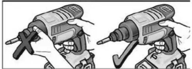
natural_image
Illustration of two hands using a drill press to adjust the drill (no text or symbols present)natural_image
Two hands performing a mechanical clamp or clamping operation, showing tool positioning and mounting details (no text or symbols visible)
VARO!
natural_image
Illustration of a drill bit with two labeled parts (1 and 2), showing the drill bit being inserted into a tool (no text or symbols present)natural_image
Mechanical assembly diagram showing a spring-loaded component being inserted into a housing (no text or symbols visible)natural_image
Mechanical assembly diagram showing a gun firing into a housing component, with an inset close-up of the tool (no text or symbols present)natural_image
Technical illustration of a mechanical tool with internal components and motion arrows (no text or symbols)natural_image
Technical illustration of a firearm with screws inserted into the jaw (no text or symbols)natural_image
Illustration of a drill bit being inserted into a screw, showing tool path and motion arrows (no text or symbols)natural_image
Illustration of a hairpin being inserted into a screwdriver, showing mechanical components and tool path (no text or symbols)natural_image
Illustration of a robotic hand holding a device with directional arrows indicating movement (no text or symbols)natural_image
Close-up of a power drill with a tool and screwdriver, showing motion arrows (no text or symbols)natural_image
Illustration of a power tool with a drill bit and tool handle, showing motion (no text or symbols)natural_image
Illustration of two hands operating a drill press, showing tool positioning and adjustment (no text or symbols)
natural_image
Illustration of two hands using a drill press to adjust the drill (no text or symbols present)Eckhard Rühle Manager Research & Development (R & D)
Klaus Peter Weinper Head of Quality Department (QD)
natural_image
Illustration of two hands fastening a mechanical clamp or bracket (no text or symbols present)
ΠΡΟΣΟΧΗ!
natural_image
Illustration of a drill bit with two labeled parts (1 and 2), showing the drill bit being inserted into a tool (no text or symbols present)natural_image
Mechanical assembly diagram showing a spring being inserted into a housing component, with an inset close-up of the component (no text or symbols visible)natural_image
Technical illustration of a mechanical tool with internal components and motion arrows (no text or symbols)natural_image
Technical illustration of a firearm with screws inserted into the jaw (no text or symbols)natural_image
Illustration of a screwdriver tool interacting with a mechanical component, showing motion arrows (no text or symbols)natural_image
Illustration of a tool being inserted into a screwdriver, showing mechanical components and assembly (no text or symbols)natural_image
Close-up of a robotic hand holding a device with an arrow pointing to the right (no text or symbols visible)natural_image
Close-up of a power tool with a screwdriver and mechanical components, no visible text or symbolsnatural_image
Illustration of a drill presser operating a tool with a pointed tip and focused on the blade (no text or symbols visible)natural_image
Illustration of two hands operating a handheld device, showing mechanical components and motion (no text or symbols)
natural_image
Illustration of two hands using a drill bit to adjust the drill (no text or symbols present)natural_image
Two mechanical clamps with screws and metal brackets, shown from different angles (no text or symbols)natural_image
Mechanical assembly diagram showing a spring-loaded component being inserted into a housing (no text or symbols visible)natural_image
Mechanical assembly diagram showing a gun firing into a housing component, with an inset close-up of the tool (no text or symbols present)natural_image
Technical illustration of a mechanical tool with internal components and motion arrows (no text or symbols)natural_image
Technical illustration of a firearm with attached screws and internal components (no text or symbols)natural_image
Illustration of a screwdriver being cut with a magnified view showing internal components (no text or symbols)natural_image
Illustration of a robotic hand holding a device with an arrow indicating motion (no text or symbols)natural_image
Close-up of a power drill with a tool and directional arrow indicator (no text or symbols)natural_image
Illustration of a power tool with a pointed tip and light beam, no text or symbols presentnatural_image
Illustration of two hands operating a drill press, showing mechanical components and tool movement (no text or symbols)
natural_image
Illustration of two hands using a drill press to adjust the drill (no text or symbols present)Eckhard Rühle Manager Research & Development (R & D)
Klaus Peter Weinper Head of Quality Department (QD)
natural_image
Illustration of two hands using a tool to adjust a mechanical component (no text or symbols present)
OSTROŻNIE!
natural_image
Mechanical assembly diagram showing a spring-loaded component being inserted into a housing (no text or symbols visible)natural_image
Mechanical assembly diagram showing a gun firing into a housing component, with an inset close-up of the tool (no text or symbols present)natural_image
Technical illustration of a mechanical tool with internal components and motion arrows (no text or symbols)natural_image
Technical illustration of a firearm with screws inserted and internal components (no text or symbols)natural_image
Illustration of a drill bit with screw fasteners and directional arrows indicating motion (no text or symbols)natural_image
Illustration of a screwdriver tool interacting with a mechanical component, showing assembly and disassembly (no text or symbols)natural_image
Illustration of a robotic hand holding a device with directional arrows indicating motion (no text or symbols)natural_image
Close-up of a power tool with a screwdriver and a magnified view showing the blade (no text or symbols visible)natural_image
Illustration of a drill presser operating a tool with a pointed tip (no text or symbols visible)natural_image
Illustration of two hands operating a drill press, showing mechanical components and tool positioning (no text or symbols)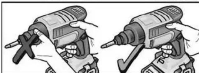
natural_image
Illustration of two hands using a drill press to adjust the drill (no text or symbols present)Eckhard Rühle
Manager Research & Development (R & D)
Klaus Peter Weinper
Head of Quality
Department (QD)
natural_image
Two hands performing a mechanical clamp or clamping operation, showing tool positioning and mounting details (no text or symbols visible)
VIGYÁZAT!
natural_image
Illustration of a drill bit with two labeled parts (1 and 2), showing the drill bit being inserted into a tool (no text or symbols present)natural_image
Mechanical assembly diagram showing a spring-loaded component being inserted into a housing (no text or symbols visible)natural_image
Technical illustration of a mechanical device with internal components and motion arrows (no text or symbols)natural_image
Technical illustration of a firearm with attached screws and internal components (no text or symbols)natural_image
Illustration of a drill bit with screw and drill bit, showing tool path and motion arrows (no text or symbols)natural_image
Illustration of a screwdriver and its internal components, showing assembly and disassembly (no text or symbols)natural_image
Illustration of a robotic hand holding a device with directional arrows indicating motion (no text or symbols)natural_image
Illustration of a power tool with a screwdriver and directional arrow (no text or symbols)natural_image
Illustration of a drill presser operating a tool with a pointed tip, showing motion blur (no text or symbols)natural_image
Illustration of two hands operating a drill press, showing mechanical components and tool movement (no text or symbols)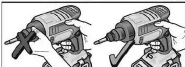
natural_image
Illustration of two hands using a drill press to adjust a tool (no text or symbols visible)Klaus Peter Weinper Head of Quality Department (QD)
17.12.2018
natural_image
Illustration of two hands using a tool to adjust a mechanical component (no text or symbols present)natural_image
Illustration of a drill bit with two labeled parts (1 and 2), showing the drill bit being inserted into a screwdriver (no text or symbols present)natural_image
Mechanical assembly diagram showing a spring-loaded component being inserted into a housing (no text or symbols visible)natural_image
Diagram showing a firearm being inserted into a housing, with an inset close-up of the component (no text or symbols present)natural_image
Cross-sectional diagram of a mechanical tool or device with internal components and motion arrows (no text or symbols)natural_image
Technical illustration of a firearm with screws inserted and internal components (no text or symbols)natural_image
Diagram showing screw fastening process with tool and directional arrows (no text or symbols)natural_image
Illustration of a tool being inserted into a screwdriver, showing mechanical components and assembly (no text or symbols)natural_image
Illustration of a robotic hand holding a device with directional arrows indicating motion (no text or symbols)natural_image
Close-up of a power drill with a tool and directional arrow indicator (no text or symbols)natural_image
Illustration of a drill presser operating a tool with a pointed tip (no text or symbols visible)natural_image
Illustration of two hands operating a drill press, showing tool positioning and adjustment (no text or symbols)
natural_image
Illustration of two hands using a drill bit to adjust the drill bit (no text or symbols present)Klaus Peter Weinper Head of Quality Department (QD)
natural_image
Two hands performing a mechanical clamp or clamping operation, showing tool positioning and mounting details (no text or symbols visible)natural_image
Illustration of a drill bit with two labeled parts (1 and 2), showing the drill bit being inserted into a tool (no text or symbols present)■ Nasad'te dorazovú objímku na skrutkovač na suché stavby.
■ Odtiahnite dorazovú objímku zo skrutkovača na suché stavby.
i UPOZORNENIE
Na povolovanie skrutiek nie je dorazové puzdro potrebné.
Zásobník skrutiek
VAROVANIE!
■ Zatlačte spojku dozadu (1.).
■ Nasad'te skrutkovací bit do uchytenia bitu (2.).
■ Povolte spojku.
natural_image
Mechanical assembly diagram showing a spring-loaded component being inserted into a housing (no text or symbols visible)■ Stlačte blokovacie tlačidlo a zasuňte sane do vedenia.
natural_image
Diagram showing a firearm being inserted into a housing component, with an inset close-up of the device (no text or symbols present)■ Stlačte blokovacie tlačidlo a vytiahnite sane.
■ Odtiahnite zásobník skrutiek zo skrutkovača na suché stavby.
natural_image
Technical illustration of a mechanical tool with internal components and motion arrows (no text or symbols)natural_image
Cross-sectional diagram of a firearm showing internal components and screws (no text or labels)natural_image
Illustration of a screwdriver tool interacting with three screws, showing mechanical assembly and motion arrows (no text or symbols)Blokovanie (45°) nastavovacieho puzdra zodpovedá zmene håbky zaskrutkovania 0,2 mm.
natural_image
Illustration of a mechanical tool interacting with a screwdriver, showing internal components and motion (no text or symbols)■ Na nastavenie híbky skrutkovania otáčajte nastavovacím kolieskom.
natural_image
Illustration of a robotic hand holding a device with an arrow indicating motion (no text or symbols present)natural_image
Close-up of a power drill with a tool and directional arrow indicator (no text or symbols)natural_image
Illustration of a power tool emitting a beam of light from a drill bit (no text or symbols visible)■ Na zapnutie a vypnutie klepnite na spínač.
Pracovné pokyny

POZOR!
natural_image
Illustration of two hands operating a drill press, showing mechanical components and tool positioning (no text or symbols)
natural_image
Illustration of two hands using a power drill press, showing tool positioning (no text or symbols)Eckhard Rühle Manager Research & Development (R & D)
Klaus Peter Weinper Head of Quality Department (QD)
natural_image
Two hands performing a manual tool manipulation technique, showing bracketing and mounting components (no text or symbols visible)■ Spojnicu pritisnite prema natrag (1.).
■ Umetnite bit izvijača u prihvat bita (2.).
■ Otpustite spojnicu.
Granična čahura

Graničnu čahuru nataknite na izvijač za suhu gradnju.
Graničnu čahuru skinite s izvijača za suhu gradnju.
i NAPUTAK!
■ Spojnicu pritisnite prema natrag (1.).
■ Umetnite bit izvijača u prihvat bita (2.).
■ Otpustite spojnicu.
Montaža spremnika za vijke:

natural_image
Mechanical assembly diagram showing a spring-loaded component being inserted into a housing (no text or symbols visible)■ Pritisnite gumb za blokadu i umetnite klizač u vodilicu.

■ Spremnik za vijke nataknite na izvijač za suhu gradnju.
Demontaža spremnika za vijke:

natural_image
Illustration of a firearm being inserted into a housing component, showing internal components and motion direction (no text or symbols)■ Pritisnite gumb za blokadu i izvucite klizač.
natural_image
Cross-sectional diagram of a mechanical tool with internal components and motion arrows (no text or symbols)■ Umetnite traku s vijcima s donje strane.
natural_image
Technical illustration of a firearm with screws inserted into the jaw (no text or symbols)natural_image
Diagram showing screw fastening process with tool and directional arrows (no text or symbols)natural_image
Illustration of a hair screw being inserted into a drill bit, showing tool path and component details (no text or symbols)natural_image
Illustration of a robotic hand holding a weapon, with directional arrows indicating movement (no text or symbols)■ Pritisnite prekidač i čvrsto ga držite. Prekidač električnog alata omogućuje postupno povećanje broja okretaja do maksimalne vrijednosti.
natural_image
Close-up of a power drill with a tool and directional arrow indicator (no text or symbols)■ Pritisnite i otpustite prekidač.
Radna svjetiljka

natural_image
Illustration of a power tool with a drill bit and tool handle, showing motion (no text or symbols)■ Za uključivanje i isključivanje pritisnite prekidač.
Upute za rad

OPREZ!
natural_image
Illustration of two hands operating a cylindrical tool, showing mechanical assembly (no text or symbols)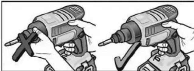
natural_image
Illustration of two hands using a drill press to adjust the tool (no text or symbols visible)Klaus Peter Weinper Head of Quality Department (QD)
17.12.2018
Hrup in tresljaji 239
natural_image
Two hands performing a mechanical clamp or clamping operation, showing tool positioning and mounting details (no text or symbols visible)Vstavljanje/menjava akumulatorske baterije
Napolnjeno akumulatorsko baterijo v električno orodje potisnite tako daleč, da se popolnoma zaskoči.
natural_image
Illustration of a drill bit with two labeled parts (1 and 2), showing the drill bit being inserted into a tool (no text or symbols present)■ Sklopko potisnite nazaj (1.).
Vijačni nastavek vstavite v vpenjalo za nastavke (2.).
■ Spustite sklopko.
Prislonska puša
■ Prislonsko pušo namestite na vijačnik za suhomontažno gradnjo.
■ Prislonsko pušo snemite z vijačnika za suhomontažno gradnjo.
i OPOMBA
■ Sklopko potisnite nazaj (1.).
■ Vijačni nastavek vstavite v vpenjalo za nastavke (2.).
■ Spustite sklopko.
natural_image
Mechanical assembly diagram showing a spring-loaded component being inserted into a housing (no text or symbols visible)■ Pritisnite gumb za zaklepanje in vstavite sani v vodilo.
Nastavek za vijačenje s šaržerjem namestite na vijačnik za suhomontažno gradnjo.
■ Pritisnite gumb za zaklepanje in vstavite izvlecite sani.
Nastavek za vijačenje s šaržerjem snemite z vijačnika za suhomontažno gradnjo.
natural_image
Cross-sectional diagram of a mechanical tool or device with internal components and motion arrows (no text or symbols)■ Trak z vijaki vstavite s spodnje strani.

natural_image
Technical illustration of a firearm with attached screws and internal components (no text or symbols)natural_image
Illustration of a drill bit with screw and drill bit, showing tool path and motion arrows (no text or symbols)En korak (45°) nastavitvene puše ustreza spremembi globine vijačenja za 0,2 mm. En celoten obrat (360°) nastavitvene puše ustreza spremembi globine vijačenja za 1,6 mm.

OPOMBA
natural_image
Illustration of a screwdriver tool interacting with a mechanical component, showing internal components and assembly (no text or symbols)Obračajte nastavitveno kolesce, da nastavite globino vijačenja.
■ Stikalo za izbiro smeri vrtenja nastavite v želeni položaj:
- Levo: vrtenje v levo (odvijanje vijakov)
– Desno: vrtenje v desno (privijanje vijakov)
natural_image
Illustration of a robotic hand holding a device with an arrow indicating motion (no text or symbols present)natural_image
Close-up of a power drill with a tool and directional arrow indicator (no text or symbols)■ Pritisnite in spustite stikalo.
natural_image
Illustration of a power tool with a pointed tip and light beam, showing mechanical components (no text or symbols)■ Za vklop in izklop pritisnite stikalo.
Navodila za delo

POZOR!
natural_image
Illustration of two hands operating a drill press, showing mechanical components and tool movement (no text or symbols)
natural_image
Illustration of two hands using a drill press to adjust the drill (no text or symbols present)- Vstavite ustrezni vijačni nastavek.
- Nastavite globino vijačenja.
- Izberite smer vrtenja (desno).
- Z eno roko primite električno orodje za ročaj in ga namestite v delovni položaj.
- Vijak nastavite na vijačni nastavek. Magnetna sila drži vijak na mestu.
- Konico vijaka pritisnite ob obdelovanec, da se prislonska puša prisloni na obdelovanec. Električno orodje držite pod pravim kotom glede na površino obdelovanca!
- Vklopite električno orodje.
- Vstavite ustrezni trak z vijaki.
- Nastavite globino vijačenja.
- Izberite smer vrtenja (desno).
- Z obema rokama primite električno orodje za ročaje in ga namestite v delovni položaj.
- Omejevalnik globine za dolžino vijakov pritisnite ob obdelovanec. Električno orodje držite pod pravim kotom glede na površino obdelovanca!
- Vklopite električno orodje. Vijak se privija v obdelovanec, dokler ne doseže nastavljene globine. Nadzorujte in po potrebi spremenite globino vijačenja.

OPOMBA
Ko je dosežena prednastavljena globina vijačenja, se pogon zaustavi in vijačni nastavek se neha vrteti.
- Po končanem privijanju vijakov izklopite električno orodje.
Po končanem delu:
- Ročico za izbiro smeri vrtenja (3) pomaknite v sredinski položaj.
Vzdrževanje in nega

OPOZORILO!
Klaus Peter Weinper Head of Quality Department (QD)
natural_image
Two hands performing a mechanical clamp or clamping operation, showing tool positioning and mounting details (no text or symbols visible)Introducerea sculelor
Bit de şurubelniţă

AVERTIZARE!
natural_image
Mechanical assembly diagram showing a spring-loaded component being inserted into a housing (no text or symbols visible)natural_image
Mechanical assembly diagram showing a gun with internal components and a close-up of the gun's internal structure (no text or symbols present)natural_image
Technical illustration of a mechanical tool with internal components and motion arrows (no text or symbols)■ Fixați de la nivel inferior cureaua cu şuruburi.
natural_image
Technical illustration of a firearm with attached screws and internal components (no text or symbols)natural_image
Illustration of a drill bit with screw fasteners and directional arrows indicating motion (no text or symbols)natural_image
Illustration of a hairpin being inserted into a screwdriver, showing mechanical components and tool positioning (no text or symbols)natural_image
Illustration of a robotic hand holding a device with directional arrows indicating motion (no text or symbols)natural_image
Close-up of a power tool with a screwdriver and a circular indicator symbol (no text or labels visible)natural_image
Illustration of a power tool with a pointed tip and light beam, showing mechanical components (no text or symbols)natural_image
Illustration of two hands operating a drill press, showing mechanical components and tool positioning (no text or symbols)
natural_image
Illustration of two hands using a drill press to adjust the drill (no text or symbols present)Directivei 2014/30/UE, 2006/42/CE, 2011/65/UE.
Responsabili pentru documente tehnice: FLEX-Elektrowerkzeuge GmbH, R & D Bahnhofstrasse 15, D-71711 Steinheim/Murr
Eckhard Rühle
Manager Research &
Development (R & D)
Klaus Peter Weinper
Head of Quality
Department (QD)
17.12.2018
natural_image
Two hands performing a mechanical clamp or clamping operation, showing tool positioning and mounting details (no text or symbols visible)natural_image
Illustration of a drill bit with two numbered components (1 and 2), showing the drill bit being inserted into a tool (no text or symbols present)natural_image
Mechanical assembly diagram showing a spring-loaded component being inserted into a housing (no text or symbols visible)natural_image
Diagram showing a firearm being inserted into a mechanical housing, with an inset close-up of the component (no text or symbols present)natural_image
Cross-sectional diagram of a mechanical tool or device with internal components and motion arrows (no text or symbols)natural_image
Technical illustration of a firearm with screws inserted into the jaw (no text or symbols)natural_image
Illustration of a drill bit with screw and drill bit, showing tool path and motion arrows (no text or symbols)natural_image
Illustration of a hairpin being inserted into a screwdriver, showing mechanical components and tool path (no text or symbols)natural_image
Illustration of a robotic hand holding a device with an arrow indicating motion (no text or symbols)natural_image
Close-up of a power tool with a screwdriver and a circular arrow indicator (no text or symbols)natural_image
Illustration of a drill presser operating a tool with a pointed tip and light beam (no text or symbols)natural_image
Four-panel illustration showing hands using a drill press to adjust the drill (no text or symbols present)Klaus Peter Weinper Head of Quality Department (QD)
natural_image
Two hands performing a mechanical clamp or clamping operation, showing tool positioning and mounting details (no text or symbols visible)natural_image
Mechanical assembly diagram showing a spring-loaded component being inserted into a housing (no text or symbols visible)natural_image
Technical illustration of a mechanical tool with internal components and motion arrows (no text or symbols)natural_image
Technical illustration of a firearm with screws inserted into the jaw (no text or symbols)natural_image
Illustration of a hairpin being inserted into a screwdriver, showing mechanical components and tool path (no text or symbols)natural_image
Illustration of a robotic hand holding a device with directional arrows indicating motion (no text or symbols)natural_image
Close-up of a power drill with a tool and directional arrow indicator (no text or symbols)natural_image
Close-up of a drill bit with a tool, showing blade and tip (no text or symbols visible)natural_image
Illustration of two hands operating a drill pen, showing mechanical components and tool positioning (no text or symbols)
natural_image
Illustration of two hands using a drill press to lift a tool, showing mechanical components (no text or symbols)Eckhard Rühle
Manager Research & Development (R & D)
Klaus Peter Weinper
Head of Quality
Department (QD)
17.12.2018
natural_image
Illustration of two hands using a tool to adjust or install a mechanical component (no text or symbols visible)Aku sisestamine/vahetamine
natural_image
Illustration of a drill bit with two labeled parts (1 and 2), showing the drill bit being inserted into a cylindrical component (no text or symbols present)■ Suruge sidurit tagasi (1.).
■ Asetada kruviotsak otsakuhoidjasse (2.).
■ Vabastage sidur.
Hülss
■ Suruge sidurit tagasi (1.).
■ Asetada kruviotsak otsakuhoidjasse (2.).
■ Vabastage sidur.
Kruvisalve paigaldamine
natural_image
Mechanical assembly diagram showing a spring-loaded component being inserted into a housing (no text or symbols visible)natural_image
Diagram showing a firearm being inserted into a housing component, with an inset close-up of the device (no text or symbols present)natural_image
Cross-sectional diagram of a mechanical device showing internal components and motion arrows (no text or symbols)■ Lükake kruvilint alt sisse.

natural_image
Technical illustration of a firearm with screws inserted and internal components (no text or symbols)natural_image
Illustration of a screwdriver tip fastening a screw, showing tool path and motion arrows (no text or symbols)natural_image
Illustration of a screwdriver and its internal components, showing assembly and disassembly (no text or symbols)natural_image
Illustration of a robotic hand holding a device with directional arrows indicating motion (no text or symbols)natural_image
Close-up of a power drill with a tool and directional arrow indicator (no text or symbols)natural_image
Illustration of a drill presser using a tool to lift a light bulb (no text or symbols visible)natural_image
Illustration of two hands operating a handheld device, showing mechanical components and motion (no text or symbols)
natural_image
Illustration of two hands using a drill press to adjust the tool (no text or symbols visible)Eckhard Rühle
Manager Research &
Development (R & D)
Klaus Peter Weinper
Head of Quality
Department (QD)
17.12.2018
natural_image
Two hands performing a mechanical clamp or clamping operation, showing tool positioning and mounting details (no text or symbols visible)natural_image
Mechanical assembly diagram showing a spring-loaded component being inserted into a housing (no text or symbols visible)natural_image
Cross-sectional diagram of a mechanical tool or device with internal components and motion arrows (no text or symbols)natural_image
Technical illustration of a mechanical device with screws and internal components (no text or symbols)lsukimo gylio keitimas
Atraminè gilzè

ATSARGIA!!
natural_image
Diagram showing screw installation process with tool and directional arrows (no text or symbols)natural_image
Illustration of a screwdriver being inserted into a tool, showing internal components and assembly (no text or symbols)natural_image
Illustration of a robotic hand holding a device with directional arrows indicating motion (no text or symbols)natural_image
Close-up of a power drill with a tool and directional arrow indicator (no text or symbols)natural_image
Illustration of a drill presser operating a tool with a pointed tip and focused on the blade (no text or symbols visible)natural_image
Illustration of two hands operating a drill press, showing mechanical components and motion (no text or symbols)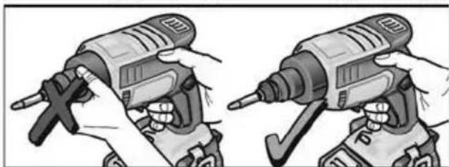
natural_image
Illustration of two hands using a drill press to adjust a tool (no text or symbols visible)Eckhard Rühle
Manager Research & Development (R & D)
Klaus Peter Weinper
Head of Quality
Department (QD)
17.12.2018
natural_image
Illustration of two hands using a tool to adjust or install a mechanical component (no text or symbols visible)natural_image
Mechanical assembly diagram showing a spring-loaded component being inserted into a housing (no text or symbols visible)natural_image
Diagram showing a firearm being inserted into a housing component, with an inset close-up of the device (no text or symbols present)natural_image
Technical illustration of a mechanical tool with internal components and motion arrows (no text or symbols)natural_image
Technical illustration of a firearm with screws inserted into the jaw (no text or symbols)natural_image
Illustration of a screwdriver tip fastening a screw, showing mechanical components and tool path (no text or symbols)natural_image
Illustration of a tool being inserted into a screwdriver, showing mechanical components and assembly (no text or symbols)natural_image
Illustration of a robotic hand holding a weapon, with motion arrows indicating movement (no text or symbols)natural_image
Close-up of a power drill with tool and screwdriver (no visible text or symbols)■ Nospiediet slēdzi un atlaidiet.
natural_image
Illustration of a drill presser operating a tool with a pointed tip and focused on the blade (no text or symbols visible)natural_image
Illustration of two hands operating a cylindrical tool, showing motion and assembly (no text or symbols)
natural_image
Illustration of two hands using a drill press to adjust the drill (no text or symbols present)Klaus Peter Weinper Head of Quality Department (QD)
natural_image
Illustration of a drill bit with a checkmark indicating inspection or repair (no text or symbols present)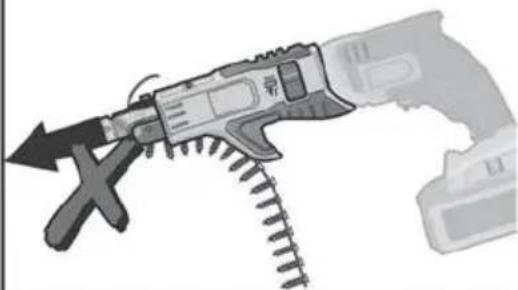
natural_image
Illustration of a handheld tool with a hammer and screwdriver, showing mechanical components (no text or symbols)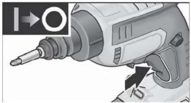
natural_image
Close-up of a power drill with a tool and directional arrow indicator (no text or symbols on the drill itself)natural_image
Illustration of a drill presser operating a tool with a pointed tip, showing motion blur (no text or symbols)natural_image
Illustration of two hands operating a drill press, showing tool positioning (no text or symbols)
natural_image
Illustration of two hands using a drill press to adjust the drill (no text or symbols present)natural_image
Illustration of a hand using a drill bit with a tool handle (no text or symbols visible)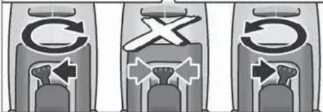
natural_image
Illustration of a robotic hand holding a device with directional arrows indicating movement (no text or symbols)natural_image
Illustration of a screwdriver being inserted into a tool, showing mechanical components and assembly (no text or symbols)natural_image
Cross-sectional diagram of a mechanical device showing internal components and motion arrows (no text or symbols)natural_image
Technical illustration of a firearm with screws inserted into the jaw (no text or symbols)تغير عمق الربط
جلبة المصد
احترس!
!
natural_image
Illustration of a screwdriver tool interacting with three screws, showing mechanical assembly and motion arrows (no text or symbols)natural_image
Mechanical assembly diagram showing a spring being inserted into a housing component, with an inset close-up of the component (no text or symbols visible)natural_image
Illustration of a firearm being inserted into a mechanical housing, showing internal components and a close-up of the tool (no text or symbols present).(1) ا Compact_Qarance لل疮
natural_image
Illustration of a drill bit with two labeled parts (1 and 2), showing the drill bit being inserted into a tool (no text or symbols present)natural_image
Mechanical assembly diagram showing two views of a tool with fasteners and bolts (no text or symbols)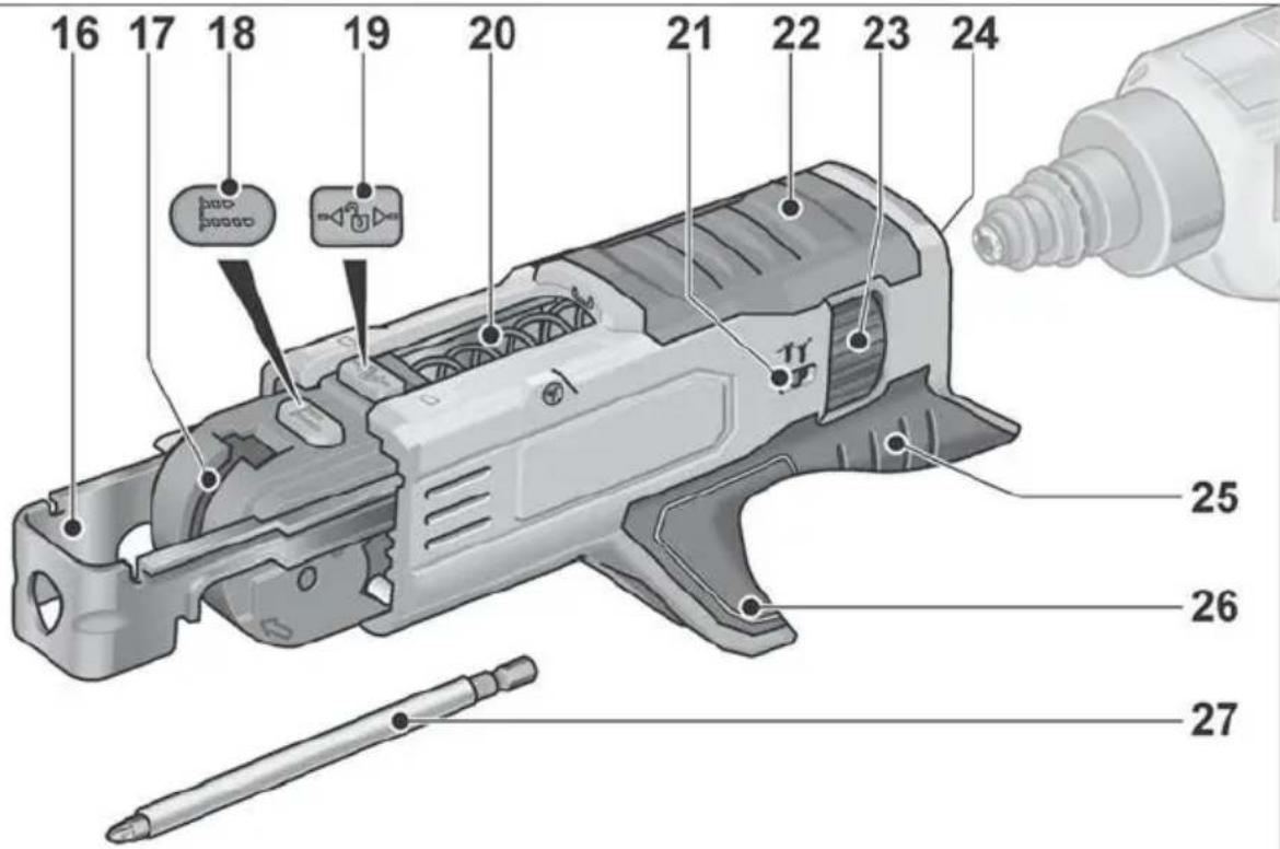
-Discounted Edem Theory: K