
FatMax FMHT0-77422 - Thermometer STANLEY - Free user manual and instructions
Find the device manual for free FatMax FMHT0-77422 STANLEY in PDF.
| Product Type | Non-contact Infrared Thermometer |
| Brand | STANLEY |
| Model | FatMax FMHT0-77422 |
| Measurement Range | -50°C to 1350°C (-58°F to 2462°F) |
| Accuracy (at 18-28°C) | ±1.5% of reading + 2°C (from -20°C to 200°C); ±2% + 2°C (200-538°C); ±3% + 5°C (538-1350°C) |
| Distance to Spot Ratio | 20:1 |
| Adjustable Emissivity | 0.1 to 1.0 (default 0.95) |
| Response Time | < 1 second |
| Display | LCD Display with Backlight |
| Power Supply | 1 9V battery (6F22 or equivalent) |
| Auto Power Off | After 1 minute of inactivity |
| Laser | Class 2, <1mW, 630-680 nm |
| Protection Rating | IP20 |
| Operating Temperature | 0°C to 40°C |
| Storage Temperature | -20°C to 50°C |
| Operating Humidity | 10% to 95% RH non-condensing up to 30°C |
| Main Functions | MAX, MIN, DIF, AVG, high/low threshold alarms, backlight, laser, adjustable emissivity, automatic data hold |
| Maintenance | Clean the lens with compressed air and cotton swab; housing with soap and water. Do not immerse. |
| Safety | Do not look directly into the laser beam, avoid unintentional exposure. Class 2 laser. |
| Warranty | 1 year |
| Repairability | Repair by authorized service center only; no user-serviceable parts. |
Frequently Asked Questions - FatMax FMHT0-77422 STANLEY
User questions about FatMax FMHT0-77422 STANLEY
0 question about this device. Answer the ones you know or ask your own.
Ask a new question about this device
Download the instructions for your Thermometer in PDF format for free! Find your manual FatMax FMHT0-77422 - STANLEY and take your electronic device back in hand. On this page are published all the documents necessary for the use of your device. FatMax FMHT0-77422 by STANLEY.
USER MANUAL FatMax FMHT0-77422 STANLEY
Please read these instructions before operating the product.


Figures
B

©

D

E

F

GB
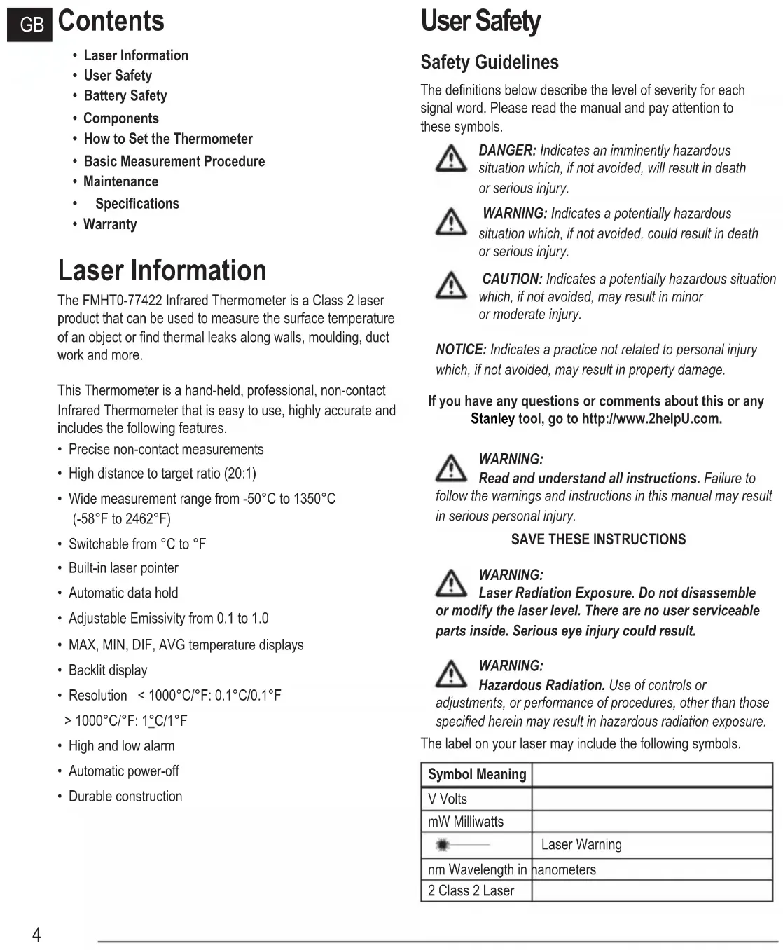
Contents
- Laser Information
- User Safety
- Battery Safety
- Components
• How to Set the Thermometer
• Basic Measurement Procedure - Maintenance
- Specifications
- Warranty
Laser Information
The FMHT0-77422 Infrared Thermometer is a Class 2 laser product that can be used to measure the surface temperature of an object or find thermal leaks along walls, moulding, duct work and more.
This Thermometer is a hand-held, professional, non-contact Infrared Thermometer that is easy to use, highly accurate and includes the following features.
- Precise non-contact measurements
• High distance to target ratio (20:1) - Wide measurement range from -50°C to 1350°C (-58°F to 2462°F)
- Switchable from °C to °F
• Built-in laser pointer
• Automatic data hold - Adjustable Emissivity from 0.1 to 1.0
• MAX, MIN, DIF, AVG temperature displays - Backlit display
• Resolution < 1000°C/°F: 0.1°C/0.1°F1000°C/°F: 1°C/1°F
• High and low alarm
• Automatic power-off
• Durable construction
User Safety
Safety Guidelines
The definitions below describe the level of severity for each signal word. Please read the manual and pay attention to these symbols.

DANGER: Indicates an imminently hazardous situation which, if not avoided, will result in death or serious injury.

WARNING: Indicates a potentially hazardous situation which, if not avoided, could result in death or serious injury.

CAUTION: Indicates a potentially hazardous situation which, if not avoided, may result in minor or moderate injury.
NOTICE: Indicates a practice not related to personal injury which, if not avoided, may result in property damage.
If you have any questions or comments about this or any Stanley tool, go to http://www.2helpU.com.

WARNING:
Read and understand all instructions. Failure to
follow the warnings and instructions in this manual may result in serious personal injury.
SAVE THESE INSTRUCTIONS

WARNING:
Laser Radiation Exposure. Do not disassemble lify the laser level. There are no user serviceable inside. Serious eye injury could result.

WARNING:
Hazardous Radiation. Use of controls or
adjustments, or performance of procedures, other than those specified herein may result in hazardous radiation exposure.
The label on your laser may include the following symbols.
| Symbol Meaning | |
| V Volts | |
| mW Milliwatts | |
| Laser Warning | |
| nm Wavelength in nanometers | |
| 2 Class 2 Laser | |
Warning Labels
For your convenience and safety, the following labels are on your laser.


WARNING: To reduce the risk of injury, user must read instruction manual.

WARNING: LASER RADIATION. DO NOT STARE INTO BEAM. Class 2 Laser Product.

- Do not operate the laser in explosive atmospheres, such as in the presence of flammable liquids, gases, or dust. This tool may create sparks which may ignite the dust or fumes.
- Store an idle laser out of reach of children and other untrained persons. Lasers are dangerous in the hands of untrained users.
- Tool service MUST be performed by qualified repair personnel. Service or maintenance performed by unqualified personnel may result in injury. To locate your nearest Stanley service centre go to http://www.2helpU.com.
- Do not use optical tools such as a telescope or transit to view the laser beam. Serious eye injury could result.
- Do not place the laser in a position which may cause anyone to intentionally or unintentionally stare into the laser beam. Serious eye injury could result.
- Do not position the laser near a reflective surface which may reflect the laser beam toward anyone's eyes. Serious eye injury could result.
- Turn the laser off when it is not in use. Leaving the laser on increases the risk of staring into the laser beam.
- Do not modify the laser in any way. Modifying the tool may result in hazardous laser radiation exposure.
- Do not operate the laser around children or allow children to operate the laser. Serious eye injury may result.
- Do not remove or deface warning labels. If labels are removed, the user or others may inadvertently expose themselves to radiation.
- Before use, verify the thermometer's operation by measuring a known temperature.
- Do not direct the laser beam toward aircraft or moving vehicles. Serious eye injury may result.
- Do not splash or immerse the unit in water.
- The measurement result of an object with high emissivity may be lower than the actual temperature of that object. Heat injury may result.

CAUTION: The laser should be protected against the following:
- Electro magnetic fields (created by arc welders, induction heaters and similar items.)
• Thermal shock caused by large or sudden ambient temperature changes. For best accuracy allow 30 minutes for the thermometer to stabilize the temperature before use. - Do not leave the laser on or near objects of high temperature.
Personal Safety
- Stay alert, watch what you are doing, and use common sense when operating the laser. Do not use the laser when you are tired or under the influence of drugs, alcohol, or medication. A moment of inattention while operating the laser may result in serious personal injury.
- Use personal protective equipment. Always wear eye protection. Depending on the work conditions, wearing protective equipment such as a dust mask, non-skid safety shoes, hard hat, and hearing protection will reduce personal injury.
Tool Use and Care
- Do not use the laser if it will not turn on or off. Any tool that cannot be controlled with the switch is dangerous and must be repaired.
- Follow instructions in the Maintenance section of this manual. Use of unauthorised parts or failure to follow Maintenance instructions may create a risk of electric shock or injury.
Battery Safety

WARNING: Batteries can explode, or leak, and can cause or fire. To reduce this risk:
- Carefully follow all instructions and warnings on the battery label and package.
GB
- Always insert batteries correctly with regard to polarity (+ and -), as marked on the battery and the equipment.
- Do not short battery terminals.
- Do not charge disposable batteries.
- Remove dead batteries immediately and dispose of per local codes.
- Do not dispose of batteries in fire.
- Keep batteries out of reach of children.
- Remove batteries when the device is not in use.
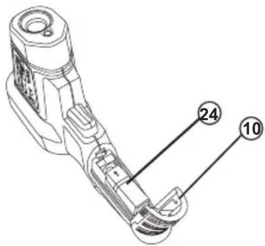
Battery Installation (Figure B)
Open the battery cover (10) by gently pressing in at the locations (23) shown in Figure B. Connect the 9V battery (24) (6F22 or equivalent), ensuring polarity. Close battery door.
Battery Replacement (Figure B)
When the symbol 📄 appears, the battery is low and should be replaced.
Wait until the thermometer turns off automatically. Open the battery cover (10) by gently pressing in at the locations (23) shown in Figure B. Replace battery with 9V battery (24) (6F22 or equivalent), ensuring polarity is correct. Close battery door.
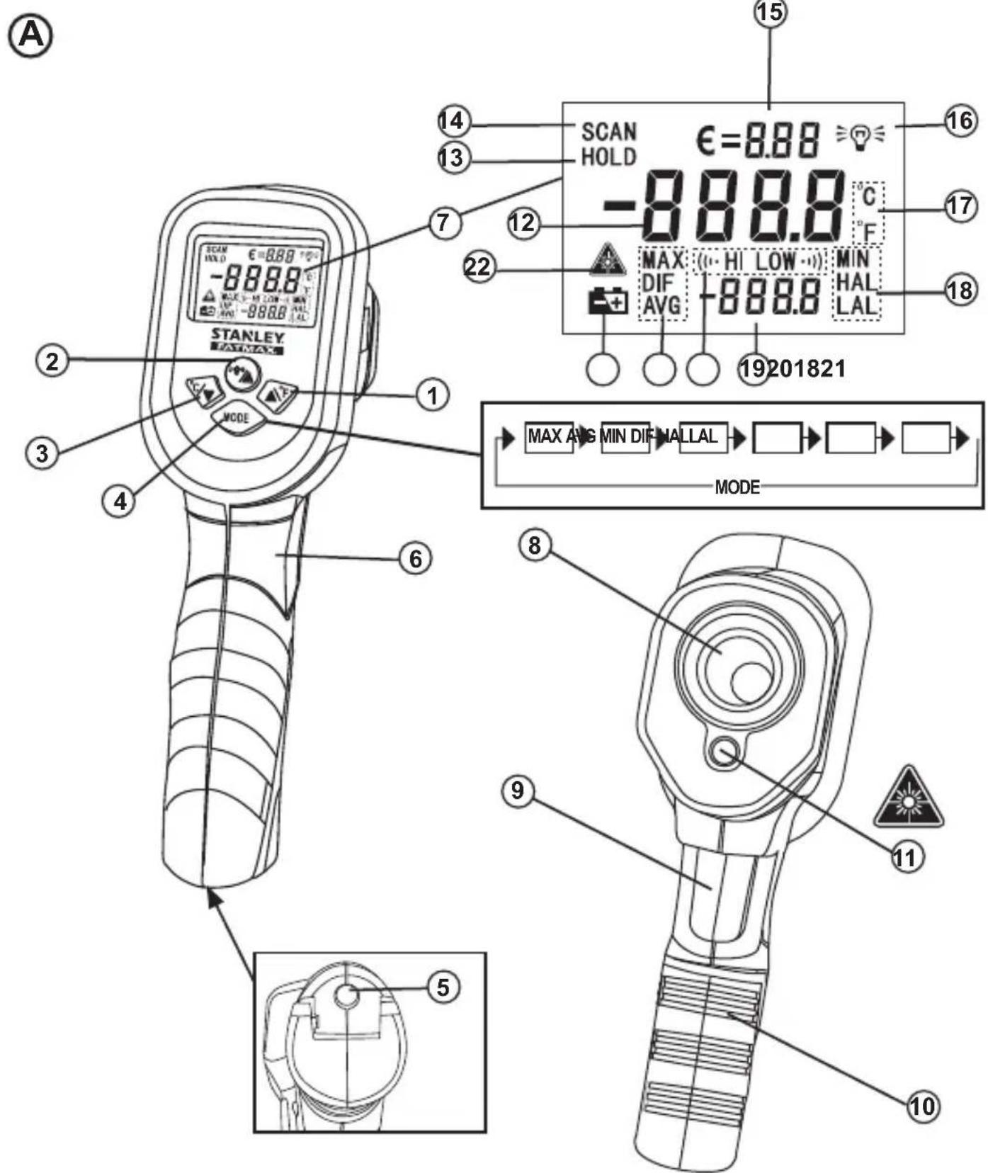
Components
THERMOMETER (Figure A)
1 Button
2 Button
3 % Button
4 MODE Button
5 Built-in 1/4-20 Nut
6 Handle
7 LCD Display
8 IR Sensor
9 Measurement Trigger
10 Battery Cover
11 Laser Pointer
NOTE: The thermometer can be attached to a suitable support with a 1/4-20 bolt using the thermometer's built in 1/4-20 nut (5).
LCD INSTRUCTION (Figure A)
12 MAIN DISPLAY shows the present reading or last reading.
13 DATA HOLD indicator appears when the reading on the main display is locked.
14 MEASUREMENT INDICATOR appears and flashes when the thermometer is taking measurements.
15 EMISSIVITY DISPLAY shows the present emissivity setting value. TIP: The symbol € means Emissivity.
16 BACKLIGHT INDICATOR appears when the backlight function is active.
17 TEMPERATURE UNIT applies to both the main display and the bottom display.
18 SYMBOLS used to indicate the kind of value being displayed on the bottom display. EXAMPLE: If the symbol "MAX" appears, the value on the bottom display is the maximum value.
19 BOTTOM DISPLAY used to display maximum (MAX), minimum (MIN), difference (DIF), average (AVG), high alarm value (HAL) and low alarm value (LAL).
20 (…HI is the high alarm icon, and LOW) alarm icon.
21 LOW BATTERY INDICATOR - + : Replace the battery immediately when the low battery indicator appears.
22 LASER FUNCTION INDICATOR appears when the laser function is enabled. When this indicator appears, the laser pointer will emit a laser beam when the trigger is pulled.
BUTTON INSTRUCTIONS (Figure A)
1 Button
- Used to change temperature units from Celsius to Fahrenheit value(s).
- When setting emissivity ( € ), high alarm value (HAL), or low alarm value (LAL), press this ▲ button to increase the value to be set
2 Button
- Press this button to turn on or off the backlight.
- To enable or disable the laser function, press button while pulling and holding the trigger. When the laser function is enabled, the symbol appears.


3 Button
- Used to change temperature units from Fahrenheit to Celsius.
- When setting emissivity ( € ), high alarm value ( HAL), or low alarm value ( LAL), press this Button to decrease the value to be set.
4 MODE Button
- Each time you pull the trigger (for > 1 sec) to take measurements, the thermometer records the maximum (MAX), minimum (MIN), the differential (DIF) between the maximum and the minimum, and the average (AVG) of all readings taken during this pull. These data are stored in memory and can be recalled with the MODE button until you pull the trigger (> 1 sec) once more. When you pull the trigger (> 1 sec) once more, all these data will be erased from memory and the thermometer will start a new recording.
- When you pull and hold the trigger, the reading on the main display will update every second with the temperature of the target surface, and when you release the trigger, the last reading is locked until you take new measurement or the thermometer turns off automatically.
- You can press the MODE button to display the maximum (MAX), average (AVG), minimum (MIN), difference (DIF), low alarm value (LAL) and high alarm value (HAL) sequentially on the bottom display. The process is illustrated in Figure A.
NOTE:
- To read value correctly, please observe the bottom display carefully to see whether the negative sign „-” and the decimal point appear.
- After you disconnect the battery from the thermometer for a while, all the settings will be restored to default values and all the recorded measurement data will be erased from memory.
How to Set the Thermometer
GB
Setting the High Alarm and Low Alarm
- After the thermometer has been turned on, press and hold down the MODE button until the symbol flashes, then release the button.
- Press the MODE button until LAL appears and flashes, now the present low alarm value is being shown on the bottom display.
- Press the % button to decrease or the button to increase the low alarm value.
NOTE: Press and hold down the % or button for fast adjustment.
- After setting the low alarm value, press the MODE button. HAL flashes and the high alarm value is shown on the bottom display. Use the same method of Step 3 to adjust the high alarm value.
- If the temperature of target surface reaches or is lower than the low alarm value, LOW ⋯ icon will appear and flash and the built-in buzzer will beep and the LCD will momentarily turn blue when you press and hold the trigger. If the temperature of target surface reaches or is higher than the high alarm value, (icon) will appear and flash and the buzzer will beep and the LCD will momentarily turn red when you press and hold the trigger.
- At any time, you can press and hold down the MODE button to exit setting mode.
NOTE:
- Alarm accuracy is ± 1°C (or ± 2°F ).
- The low and high alarm values can be set only within the thermometer's measurement range.
- The high alarm value must be higher than the low alarm value.
Emissivity/ Setting Emissivity
Emissivity describes the energy-emitting characteristics of materials. Most (90% of typical applications) organic materials or non-shiny surfaces have an emissivity of 0.95 in the default setting. Inaccurate readings will result from measuring shiny or polished metal surfaces. To compensate, cover the surface to be measured with masking tape or flat paint. Allow the tape or paint to reach the same temperature as the surface it is covering. Then measure the temperature of the covered surface.
Emissivity Values
| Substance Emissivity Substance Emissivity | |||
| Asphalt 0.90 - 0.98 Brick 0.93 - 0.96 | |||
| Concrete | 0.94 | Cloth (black) | 0.98 |
| Cement 0.96 Human skin 0.98 | |||
| Sand 0.90 Lather 0.75 - 0.80 | |||
| Earth | 0.92 - 0.96 | Charcoal (powder) | 0.96 |
| Water 0.92 - 0.96 Lacquer 0.80 - 0.95 | |||
| Ice | 0.96 - 0.98 | Lacquer (matt) | 0.97 |
| Snow | 0.83 | Rubber (black) | 0.94 |
| Glass 0.90 - 0.95 Plastic 0.85 - 0.95 | |||
| Ceramic 0.90 - 0.94 Timber 0.90 | |||
| Marble 0.94 Paper 0.70 - 0.94 | |||
| Plaster 0.80 - 0.90 Textiles 0.90 | |||
| Mortar | 0.89 - 0.91 | ||
You can adjust the thermometer's emissivity setting value so it can match the type of surface to be measured.
How to Set Emissivity
- When the thermometer is on, press and hold down the MODE button until the symbol € flashes, then release the button.
- Press the ⚠▼ button to decrease or the △F button to increase the emissivity setting value.
- When you finish emissivity setting, press and hold down the MODE button until the symbol € stops flashing. The thermometer returns to normal operation.
Basic Measurement Procedure
- Hold the thermometer by its handle, and point it toward the surface to be measured.
- Pull and hold the trigger for at least 1 sec to turn on the thermometer and take measurement. Reading will be displayed on the main display.
NOTE: Each time the trigger is pulled, the pull must last at least 1 sec. The laser pointer (26, Figure F) is for reference only.
- During measurement, the symbol SCAN will flash on the main display, and when the trigger is released, the measurement stops and the symbol HOLD appears indicating that the last reading is locked.
- The thermometer will turn off automatically after about 50 seconds if the trigger or no buttons are pressed.
NOTE:
- Make sure the target surface is larger than the thermometer's spot size. The smaller the target surface, the closer you should be to it (Refer to Field Of View section). When accuracy is critical, make sure the target is at least twice as large as the spot size.
- To find a hot or cold spot, aim the thermometer outside the desired area (25). Press and hold the trigger, slowly scan back and forth across the area until you locate the hot or cold spot. Refer to Figure C.
Measurement Considerations
- Laser beam is mainly used to locate far objects. To save battery power, disable the laser function when measuring near objects.
- The thermometer can not measure through transparent surfaces such as glass. It will measure the surface temperature of the glass instead.
- Steam, dust, smoke, etc., can prevent accurate measurement by interfering with the energy emitted from the target.
MAINTENANCE
To Clean the Lens
Blow off loose dust and dirt with compressed air. Carefully wipe the surface with a moist cotton swab. Don't use abrasive or solvent.
To Clean the Thermometer Housing
Use soap and water on a damp soft cloth. Don't use abrasives or solvent.
NOTE:
Do not immerse the thermometer in water, and do not let any liquid enter the case.
SPECIFICATION
Temperature Range: -50°C to 1350°C ( -58°F to 2462°F )
Accuracy:
| Range Accuracy* | ||
| Celsius -50°C | C to - 20°C ± 5°C | |
| -20°C to 200°C ± | (1.5% of reading + 2°C) | |
| 200°C to 538°C ± | (2.0% of reading + 2°C) | |
| 538°C to 1350°C ± | (3.0% of reading + 5°C) | |
| Fahrenheit | -58°F to -4°F ± 9°F | |
| -4°F to 392°F ± | (1.5% of reading + 3.6°F) | |
| 392°F to 1000°F ± | (2.0% of reading + 3.6°F) | |
| 1000°F to 2462°F ± | (3.0% of reading + 9°F) | |
* Accuracy specification assumes that the ambient operating temperature is 18°C to 28°C (64°F - 82°F) and the operating relative humidity is less than 80%.
Specifications
| Response Time: < 1 sec | |
| Response Wavelength: 8μm to 14μm | |
| Emissivity: Adjustable from 0.1 to 1.0(0.95 default value) | |
| Distance to Spot Ratio: | 20:1 |
| Auto-off: | After 1 minute of inactivity |
| Batteries: | 1 x 9V battery,6F22 or equivalent |
| IP Rating: | IP20 |
| Operating Temperature: | Temperature: 0°C to 40°C |
| Relative humidity: | 10% to 95% RH,noncondensing @up to 30°C |
| Storage Temperature: | -20°C to 50°C |
| Laser Class: | 2 |
| Laser Power: | ≤1mW |
| Laser Wavelength: 630-680nm | |
Field of View (Figures D–F)
The farther the thermometer is from a target, the larger the target area will be, this is known as the distance to spot (D:S=20:1) ratio. For example: at a distance of 508 mm the spot will be 25.4 mm in diameter. The thermometer will display the average temperature across the target area.
DISTANCE: SPOT = 90% Energy
DISTANCE: SPOT ratio 20:1
NOTE: For best accuracy make sure the object to be measured is larger then the thermometer's spot size.
The thermometer has a visible red laser point (26) in the centre of eight outer dots. The red laser point shows the approximate location where the temperature is being measured. The outer dot pattern will become larger with distance. Figure E shows the laser point and outer dots near, Figure F shows the laser point and outer dots farther away.
NOTE: The laser point is only an approximate location, it is not an exact location.
GB
GB
1-YEAR WARRANTY
Stanley warrants its electronic measuring tools against deficiencies in materials and / or workmanship for one year from date of purchase.
Deficient products will be repaired or replaced, at
Stanley's option, if sent together with proof of purchase to:
Stanley Black & Decker
210 Bath Road
Slough, Berkshire SL1 3YD
UK
This Warranty does not cover deficiencies caused by accidental damage, wear and tear, use other than in accordance with the manufacturer's instructions or repair or alteration of this product not authorised by Stanley.
Repair or replacement under this Warranty does not affect the expiry date of the Warranty.
To the extent permitted by law, Stanley shall not be liable under this Warranty for indirect or consequential loss resulting from deficiencies in this product.
This Warranty may not be varied without the authorisation of Stanley.
This Warranty does not affect the statutory rights of consumer purchasers of this product.
This Warranty shall be governed by and construed in accordance with the laws of the country sold where in and Stanley and the purchaser each irrevocably agrees to submit to the exclusive jurisdiction of the courts of that country over any claim or matter arising under or in connection with this Warranty.
Calibration and care are not covered by warranty.
NOTE:
The customer is responsible for the correct use and care of the instrument. Moreover, the customer is completely responsible for periodically checking the accuracy of the laser unit, and therefore for the calibration of the instrument.
This manual is subject to change without notice.
DISPOSAL OF THIS ARTICLE
Dear Customer,
If you at some point intend to dispose of this article, then please keep in mind that many of its components consist of valuable materials, which can be recycled.
Please do not discharge it in the garbage bin, but check with your local council for recycling facilities in your area.

Inhalt
THERMOMÈTRE (Figure A)
1 Bouton
2 Bouton
3 Bouton


4 Bouton MODE
WAARSCHUWING: LASER-STRALING.
Kijk NIET IN DE STRAAL.
Klasse 2 Laser-product.

AFSTAND: SPOT = 90 % Energy
AFSTAND: SPOT-verhouding 20:1
DIT ARTIKEL ALS AFVAL VERWERKEN
Geachte Klant,
Synsfelt (Figur D-F)
TERMOMETER (figur A)
1 knapp
2 knapp
3 % knapp
4 MODUS-knapp
Synsfelt (figur D–F)
AVHENDING AV DETTE PRODUKTET
Kjære kunde,
TYTO POKYNY USCHOVEJTE

POPIS LCD DISPLEJE (obr. A)
TIETO POKYNY USCHOVAJTE

10 Capac accumulator
11 Indicator laser
TERMOMETRS (A. attêls)
- Poga
- Poga
- Poga


POGU APZİMËJUMU NOZİME (A. attëls)
1. Poga

MESAFE: NOKTA oran 20:1
© 2017 Stanley Tools
- GB
- CONTENTS
- LASER INFORMATION
- USER SAFETY
- SAFETY GUIDELINES
- SAVE THESE INSTRUCTIONS
- WARNING LABELS
- PERSONAL SAFETY
- TOOL USE AND CARE
- BATTERY SAFETY
- BATTERY INSTALLATION (FIGURE B)
- BATTERY REPLACEMENT (FIGURE B)
- COMPONENTS
- THERMOMETER (FIGURE A)
- LCD INSTRUCTION (FIGURE A)
- BUTTON INSTRUCTIONS (FIGURE A)
- 3 BUTTON
- 4 MODE BUTTON
- NOTE
- HOW TO SET THE THERMOMETER
- SETTING THE HIGH ALARM AND LOW ALARM
- EMISSIVITY/ SETTING EMISSIVITY
- EMISSIVITY VALUES
- HOW TO SET EMISSIVITY
- BASIC MEASUREMENT PROCEDURE
- MEASUREMENT CONSIDERATIONS
- MAINTENANCE
- TO CLEAN THE LENS
- TO CLEAN THE THERMOMETER HOUSING
- SPECIFICATION
- FIELD OF VIEW (FIGURES D–F)
- 1-YEAR WARRANTY
- STANLEY BLACK & DECKER
- 210 BATH ROAD
- SLOUGH, BERKSHIRE SL1 3YD
- UK
- DISPOSAL OF THIS ARTICLE
- INHALT
- THERMOMÈTRE (FIGURE A)
- DIT ARTIKEL ALS AFVAL VERWERKEN
- SYNSFELT (FIGUR D-F)
- TERMOMETER (FIGUR A)
- SYNSFELT (FIGUR D–F)
- AVHENDING AV DETTE PRODUKTET
- POPIS LCD DISPLEJE (OBR. A)
- TIETO POKYNY USCHOVAJTE
- TERMOMETRS (A. ATTÊLS)
- POGU APZİMËJUMU NOZİME (A. ATTËLS)
- POGA
Brand : STANLEY
Model : FatMax FMHT0-77422
Category : Thermometer