GNB 18V-38 Professional - Stapler BOSCH - Free user manual and instructions
Find the device manual for free GNB 18V-38 Professional BOSCH in PDF.
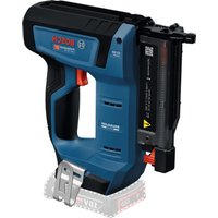
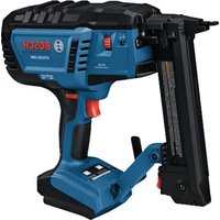
| Product type | Cordless nail gun |
| Brand and model | Bosch GNB 18V-38 Professional |
| Dimensions (L × W × H) | 405 × 138 × 309 mm |
| Weight without battery | 4.1 kg |
| Weight with battery | 4.4–5.4 kg (depending on battery) |
| Rated voltage | 18 V |
| Compatible battery type | Lithium-Ion GBA 18V... / ProCORE18V... |
| Recommended chargers | GAL 18..., GAX 18V..., GAL 36... |
| Staple/nail type | Bosch nails (NB, NK, NM) or NB-40 (GNB 18V-40) |
| Nail length | 13–38 mm (GNB 18V-38) / 13–40 mm (GNB 18V-40) |
| Shank diameter | 2.7–3 mm |
| Magazine capacity | Up to 22 nails (2 strips) |
| Maximum driving frequency | 2 nails per second (with battery ≥ 4 Ah) |
| Trigger system | Single shot with safety sequence |
| Compatible materials | Concrete (cast, compacted joints), structural steel |
| Operating temperature | -5 °C to +50 °C |
| Sound pressure level | 85 dB(A) |
| Sound power level | 96 dB(A) |
| Vibrations (a_h) | 5.7 m/s² (uncertainty K = 1.5 m/s²) |
| Maintenance | Clean the tool and ventilation slots regularly |
| Safety | Contact element (safety), lockable trigger, battery removal mandatory before maintenance |
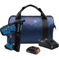
| Box contents | Tool, support foot, suspension hook, manual (battery and charger may be sold separately) |
| Warranty / Service | Bosch after-sales service (phone: 09 70 82 12 26); parts available online |
Frequently Asked Questions - GNB 18V-38 Professional BOSCH
User questions about GNB 18V-38 Professional BOSCH
0 question about this device. Answer the ones you know or ask your own.
Ask a new question about this device
Download the instructions for your Stapler in PDF format for free! Find your manual GNB 18V-38 Professional - BOSCH and take your electronic device back in hand. On this page are published all the documents necessary for the use of your device. GNB 18V-38 Professional by BOSCH.
USER MANUAL GNB 18V-38 Professional BOSCH
natural_image
Exterior view of a mechanical power nacety device (no visible text or symbols)text_image
(1) (2) (3) (4) ON/OFF RESET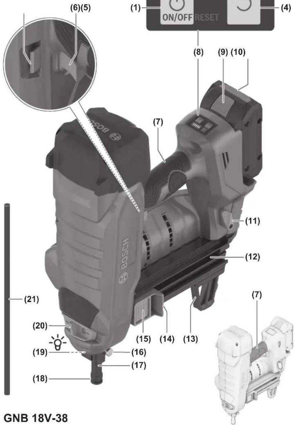
text_image
(6)(5) (1) ON/OFF RESET (4) (8) (9) (10) (7) (21) (11) (12) (13) (14) (15) (16) (17) (18) (19) (20) GNB 18V-384
text_image
A (12)
text_image
(11) HOSOB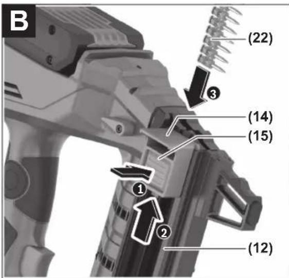
text_image
B (22) (14) (15) ① ② (12)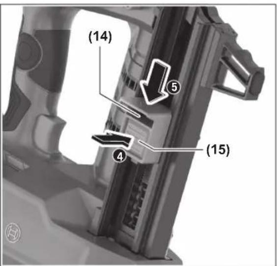
text_image
(14) ⑤ ④ (15)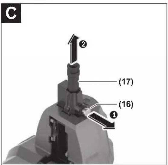
text_image
C ② (17) (16) ①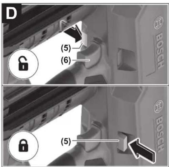
text_image
D (5) (6) BOSCH (5) BOSCH1 609 92A 9HC | (14.06.2024) Bosch Power Tools
text_image
E GNB 18V-40 (23)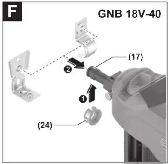
text_image
F GNB 18V-40 (17) (2) (24)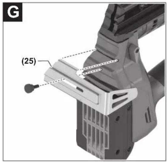
text_image
(25)Deutsch
Sicherheitshinweise
natural_image
Two mechanical diagrams showing a tool interacting with a surface, one marked with an X and the other with a checkmark (no text or symbols present)natural_image
Two mechanical diagrams showing a tool interacting with a surface, one with a cross mark and the other with a checkmark (no text or symbols present)natural_image
Illustration of a hand holding a cross over a pipe with a tool, no text or symbols present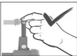
natural_image
Hand holding a tool with a checkmark, no visible text or symbolswww.bosch-pt.com/serviceaddresses
Transport
General Power Tool Safety Warnings
WARNING
Read all safety warnings and all instructions. Failure to follow the
warnings and instructions may result in electric shock, fire and/or serious injury.
Save all warnings and instructions for future reference.
The term "power tool" in the warnings refers to your mains-operated (corded) power tool or battery-operated (cordless) power tool.
Work area safety
▶ Keep work area clean and well lit. Cluttered or dark areas invite accidents.
▶ Do not operate power tools in explosive atmospheres, such as in the presence of flammable liquids, gases or dust. Power tools create sparks which may ignite the dust or fumes.
▶ Keep children and bystanders away while operating a power tool. Distractions can cause you to lose control.
Electrical safety
▶ Power tool plugs must match the outlet. Never modify the plug in any way. Do not use any adapter plugs with earthed (grounded) power tools. Unmodified plugs and matching outlets will reduce risk of electric shock.
▶ Avoid body contact with earthed or grounded surfaces, such as pipes, radiators, ranges and refrigerators. There is an increased risk of electric shock if your body is earthed or grounded.
▶ Do not expose power tools to rain or wet conditions.
Water entering a power tool will increase the risk of electric shock.
▶ Do not abuse the cord. Never use the cord for carrying, pulling or unplugging the power tool. Keep cord away from heat, oil, sharp edges or moving parts.
Damaged or entangled cords increase the risk of electric shock.
When operating a power tool outdoors, use an extension cord suitable for outdoor use. Use of a cord suitable for outdoor use reduces the risk of electric shock..
▶ If operating a power tool in a damp location is unavoidable, use a residual current device (RCD) protected supply. Use of an RCD reduces the risk of electric shock.
Personal safety
▶ Stay alert, watch what you are doing and use common sense when operating a power tool. Do not use a power tool while you are tired or under the influence of drugs, alcohol or medication. A moment of inattention while operating power tools may result in serious personal injury.
▶ Use personal protective equipment. Always wear eye protection. Protective equipment such as dust mask, non-skid safety shoes, hard hat, or hearing protection used for appropriate conditions will reduce personal injuries.
▶ Prevent unintentional starting. Ensure the switch is in the off-position before connecting to power source and/or battery pack, picking up or carrying the tool. Carrying power tools with your finger on the switch or energising power tools that have the switch on invites accidents.
Remove any adjusting key or wrench before turning the power tool on. A wrench or a key left attached to a rotating part of the power tool may result in personal injury.
▶ Do not overreach. Keep proper footing and balance at all times. This enables better control of the power tool in unexpected situations.
▶ Dress properly. Do not wear loose clothing or jewellery. Keep your hair, clothing and gloves away from moving parts. Loose clothes, jewellery or long hair can be caught in moving parts.
If devices are provided for the connection of dust extraction and collection facilities, ensure these are connected and properly used. Use of dust collection can reduce dust-related hazards.
Power tool use and care
▶ Do not force the power tool. Use the correct power tool for your application. The correct power tool will do the job better and safer at the rate for which it was designed.
▶ Do not use the power tool if the switch does not turn it on and off. Any power tool that cannot be controlled with the switch is dangerous and must be repaired.
▶ Disconnect the plug from the power source and/or the battery pack from the power tool before making any
adjustments, changing accessories, or storing power tools. Such preventive safety measures reduce the risk of starting the power tool accidentally.
▶ Store idle power tools out of the reach of children and do not allow persons unfamiliar with the power tool or these instructions to operate the power tool. Power tools are dangerous in the hands of untrained users.
- Maintain power tools. Check for misalignment or binding of moving parts, breakage of parts and any other condition that may affect the power tool's operation. If damaged, have the power tool repaired before use. Many accidents are caused by poorly maintained power tools.
▶ Keep cutting tools sharp and clean. Properly maintained cutting tools with sharp cutting edges are less likely to bind and are easier to control.
▶ Use the power tool, accessories and tool bits etc. in accordance with these instructions, taking into account the working conditions and the work to be performed. Use of the power tool for operations different from those intended could result in a hazardous situation.
Battery tool use and care
▶ Recharge only with the charger specified by the manufacturer. A charger that is suitable for one type of battery pack may create a risk of fire when used with another battery pack.
▶ Use power tools only with specifically designated battery packs. Use of any other battery packs may create a risk of injury and fire.
When battery pack is not in use, keep it away from other metal objects, like paper clips, coins, keys, nails, screws or other small metal objects, that can make a connection from one terminal to another. Shorting the battery terminals together may cause burns or a fire.
▶ Under abusive conditions, liquid may be ejected from the battery; avoid contact. If contact accidentally occurs, flush with water. If liquid contacts eyes, additionally seek medical help. Liquid ejected from the battery may cause irritation or burns.
Service
▶ Have your power tool serviced by a qualified repair person using only identical replacement parts. This will ensure that the safety of the power tool is maintained.
Nailer safety warnings
▶ Always assume that the tool contains nails. Careless handling of the nailer may result in unexpected firing of nails and personal injury.
▶ Do not point the tool towards yourself or anyone nearby. Unexpected triggering will discharge the nails causing an injury.
▶ Do not actuate the tool unless the tool is placed firmly against the workpiece. If the tool is not in contact with
the workpiece, the nail may be deflected away from your target.
▶ Disconnect the tool from the power source when the nail jams in the tool. While removing a jammed nail, the nailer may be accidentally activated if it is plugged in.
▶ Use caution while removing a jammed nail. The mechanism may be under compression and the nail may be forcefully discharged while attempting to free a jammed condition.
Additional safety information for GNB 18V-38:
▶ Do not use this nailer for fastening electrical cables. It is not designed for electric cable installation and may damage the insulation of electric cables thereby causing electric shock or fire hazards.
Additional Safety Information for GNB 18V-40:
When fastening electrical cables, make sure the cables are not energized. Hold the nailer only by insulated gripping surfaces. Use only nails designed for electrical cable installations. Inspect that the nails has not damaged the insulation of the electrical cables. A nail that damages the insulation of electric cables can lead to electric shock and fire hazards.
▶ Disconnect the nailer from the power source when loading and unloading nails, making adjustments or changing accessories. The nailer may be accidentally activated if it is connected to the power source, which may result in personal injury.
▶ Be careful when handling nails, especially when loading and unloading. The nails have sharp points which may result in personal injury.
▶ Keep fingers away from trigger when not operating this nailer and when moving from one operating position to another. Unexpected triggering will discharge a nail, which may result in personal injury.
▶ Hold the nailer by insulated gripping surfaces, when performing an operation where the nail may contact hidden wiring. A nail contacting a "live" wire may make exposed metal parts of the nailer "live" and could give the operator an electric shock.
▶ Hold the nailer with a firm grasp during operation. Uncontrolled recoil of the nailer may result in unintended activation, which may result in personal injury.
▶ Keep all body parts such as hands and legs, etc. away from the firing direction of the tool. The nail may penetrate the workpiece as well as any object behind it, which may result in personal injury.
When using the nailer, keep all body parts such as hands and legs, etc. away from the area where the nails is driven into the workpiece. The nail could deflect and exit the workpiece, which may result in personal injury.
▶ Use suitable detectors to determine if there are hidden supply lines or contact the local utility company for assistance. Contact with electric cables can cause
20 | English
fire and electric shock. Damaging gas lines can lead to explosion. Breaking water pipes causes property damage.
In case of damage and improper use of the battery, vapours may be emitted. The battery can set alight or explode. Ensure the area is well ventilated and seek medical attention should you experience any adverse effects. The vapours may irritate the respiratory system.
▶ Do not modify or open the battery. There is a risk of short-circuiting.
The battery can be damaged by pointed objects such as nails or screwdrivers or by force applied externally. An internal short circuit may occur, causing the battery to burn, smoke, explode or overheat.
▶ Only use the battery in the manufacturer's products. This is the only way in which you can protect the battery against dangerous overload.
Protect the battery against heat, e.g. against continuous intense sunlight, fire, dirt, water and moisture. There is a risk of explosion and short-circuiting.
▶ Do not use the power tool and the nails on very soft materials (e.g. wood, lightweight construction materials). The nails may penetrate the substrate and may cause injury.
▶ Do not use the power tool and the nails on very hard materials (e.g. high-strength steel, very hard natural stone) or on types of concrete with high compressive strength or aggregate with high compressive strength. If the material is too hard, the nail may rico-chet, break and escape and may hit you or other persons and may cause injuries.
natural_image
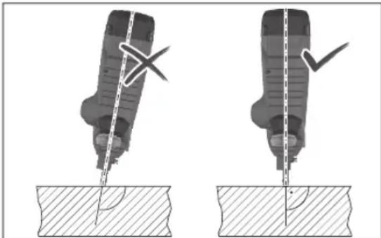
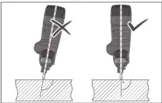
Two mechanical diagrams showing a tool pressing into a workpiece, with no visible text or symbols.▶ Never hold the power tool when it is at an acute angle to the substrate. The power tool must be perpendicular to the substrate. There must be no contamination on the substrate.
▶ Do not deactivate or remove the contact element. The contact element is a safety mechanism to reduce the risk of unintentional triggering. Deactivating this component may lead to unintentional triggering.
▶ Only use the power tool if the contact element is functioning correctly. If the contact element is defective, the power tool may trigger unexpectedly.
▶ Always fill the magazine of the power tool with nails first before you insert the battery. This reduces the risk
of accidentally discharging a nail and injuring yourself or other people.
▶ Never discharge nails in the vicinity of flammable materials. When driving in some nail types, sparks may fly out of the contact element.
▶ Never discharge a nail on top of another nail. This may lead to the nail being deflected or the power tool reacting unexpectedly.
Product Description and Specifications

Read all the safety and general instructions. Failure to observe the safety and general instructions may result in electric shock, fire and/or serious injury.
Please observe the illustrations at the beginning of this operating manual.
Intended Use
The power tool is designed to put nails into hard materials such as concrete (e.g. poured concrete, grouted joints) and steel (e.g. structural steel, hot-rolled steel).
The power tool must not be used on very soft surfaces (e.g. wood, lightweight construction materials) or very hard surfaces (e.g. high-strength steel). The power tool must also not be used on the following substrates: Natural stone, vertical mortar joints, hollow blocks, bricks, glazed brick, glass, hardened steel, tool steel, spring steel, cast iron, weld seams.
Check the suitability of the substrate before use (see "Checking the Suitability of the Substrate", page 23).
The power tool is intended for hand-held use only.
The power tool is only intended for indoor use.
Product Features
The numbering of the product features refers to the diagram of the power tool on the graphics page.
(1) On/off button (user interface)
(2) Power tool status indicator (user interface)
(3) Battery charge indicator (user interface)
(4) Reset button (user interface)
(5) Unlocking switch for trigger
(6) Trigger
(7) Handle (insulated gripping surface)
(8) User interface
(9) Battery release button ^a)
(10) Rechargeable battery ^a)
(11) Magazine release lever
(12) Magazine
(13) Supporting leg
(14) Magazine slider
(15) Magazine slider button
English | 21
(16) Contact element release button
(17) Standard contact element
(18) Outlet
(19) Worklight
(20) Depth stop switch
(21) Punch pin
(22) Nail strip ^a)
(23) Narrow contact element (GNB 18V-40)
(24) Magnet ring (GNB 18V-40)
(25) Utility hook
a) This accessory is not part of the standard scope of delivery.
Technical Data
| Cordless nailer GNB 18V-38 GNB 18V-40 | |||
| Article number | 3 601 JL7 000 3 601 JL7 001 | ||
| Rated voltage V= 18 18 | |||
| Actuation mode Full sequential Full sequential | |||
| Max. insertion frequency (with battery ≥ 4 Ah) s | -1 | 2 | 2 |
| Fastener | |||
| - Type Nail Nail | |||
| - Length mm 13-38 13-40 | |||
| - Shank diameter mm 2.7-3 2.7-3 | |||
| Standard magazine capacity | Nails 22 22 | ||
| Dimensions without rechargeable battery(length × width × height) | mm | 405 × 138 × 309 | 405 × 138 × 309 |
| Weight with battery^A) | kg | 4.4-5.4 | 4.4-5.4 |
| Weight without battery | kg | 4.1 | 4.1 |
| Recommended ambient temperature during charging | °C | 0 ... +35 | 0 ... +35 |
| Permitted ambient temperature during operation^B) | °C | -5 ... +50 | -5 ... +50 |
| Permitted ambient temperature during storage | °C | -20 ... +50 | -20 ... +50 |
| Compatible rechargeable batteries | GBA 18V...ProCORE18V... | GBA 18V...ProCORE18V... | |
| Recommended rechargeable batteries for maximum performance | ProCORE18V...≥ 4 Ah | ProCORE18V...≥ 4 Ah | |
| Recommended chargers | GAL 18...GAX 18V...GAL 36... | GAL 18...GAX 18V...GAL 36... | |
A) Depends on battery in use
B) Limited performance at temperatures < 0 °C
Values can vary depending on the product, scope of application and environmental conditions. To find out more, visit www.bosch-professional.com/wac.
Noise/Vibration Information
Noise emission values determined according to EN 60745-2-16.
Typically, the A-weighted noise level of the power tool is: Sound pressure level 85 dB(A); sound power level 96 dB(A). Uncertainty K = 3 dB.
Wear hearing protection!
Vibration total values a_n (triax vector sum) and uncertainty K determined according to EN 60745-2-16: a_n=5.7 m/s^2, K=1.5 m/s^2.
The vibration level and noise emission value given in these instructions have been measured in accordance with a standardised measuring procedure and may be used to com-
pare power tools. They may also be used for a preliminary estimation of vibration and noise emissions.
The stated vibration level and noise emission value represent the main applications of the power tool. However, if the power tool is used for other applications, with different accessories or is poorly maintained, the vibration level and noise emission value may differ. This may significantly increase the vibration and noise emissions over the total working period.
To estimate vibration and noise emissions accurately, the times when the tool is switched off or when it is running but not actually being used should also be taken into account. This may significantly reduce vibration and noise emissions over the total working period.
22 | English
Implement additional safety measures to protect the operator from the effects of vibration, such as servicing the power tool and accessories, keeping their hands warm, and organising workflows correctly.
Rechargeable battery
Bosch sells some cordless power tools without a rechargeable battery. You can tell whether a rechargeable battery is included with the power tool by looking at the packaging.
Charging the battery
▶ Use only the chargers listed in the technical data. Only these chargers are matched to the lithium-ion battery of your power tool.
Note: Lithium-ion rechargeable batteries are supplied partially charged according to international transport regulations. To ensure full rechargeable battery capacity, fully charge the rechargeable battery before using your tool for the first time.
Inserting the Battery
Push the charged battery into the battery holder until it clicks into place.
Removing the Battery
To remove the rechargeable battery, press the battery release button and pull the battery out. Do not use force to do this.
The rechargeable battery has two locking levels to prevent the battery from falling out if the battery release button is pressed unintentionally. The rechargeable battery is held in place by a spring when fitted in the power tool.
Battery charge indicator
Note: Not all battery types have a battery charge indicator. The green LEDs on the battery charge indicator indicate the state of charge of the battery. For safety reasons, it is only possible to check the state of charge when the power tool is not in operation.
Press the button for the battery charge indicator or to show the state of charge. This is also possible when the battery is removed.
If no LED lights up after pressing the button for the battery charge indicator, then the battery is defective and must be replaced.
The state of charge of the battery is also displayed on the user interface (see "Status indicators", page 26).
Battery model GBA 18V...


LED Capacity
3× continuous green light 60–100%
LED Capacity
| 2× continuous green light 30–60 % |
| 1× continuous green light 5–30 % |
| 1× flashing green light 0–5 % |
Battery model ProCORE18V...
LED Capacity
| 5 × continuous green light 80–100 % |
| 4 × continuous green light 60–80 % |
| 3 × continuous green light 40–60 % |
| 2 × continuous green light 20–40 % |
| 1 × continuous green light 5–20 % |
| 1 × flashing green light 0–5 % |
Recommendations for Optimal Handling of the Battery
Protect the battery against moisture and water.
Only store the battery within a temperature range of -20 to 50 °C. Do not leave the battery in your car in the summer, for example.
Occasionally clean the ventilation slots on the battery using a soft brush that is clean and dry.
A significantly reduced operating time after charging indicates that the battery has deteriorated and must be replaced. Follow the instructions on correct disposal.
Assembly
Before carrying out any work on the power tool (e.g. maintenance, tool change etc.), remove the battery from the power tool. There is risk of injury from unintentionally pressing the on/off switch.
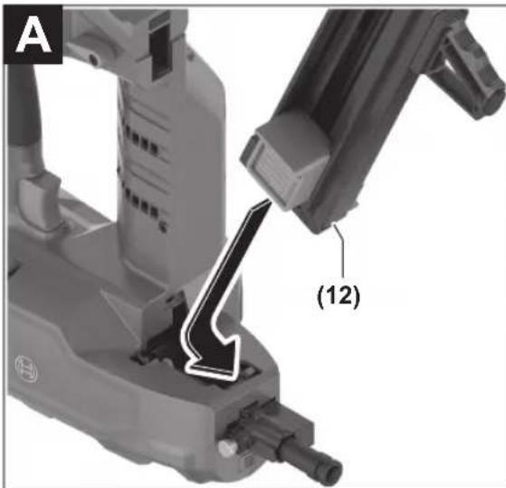
Inserting/Changing the Magazine (see figure A)
Insert the magazine (12) into the power tool and allow it to engage.
To change the magazine, press the unlocking lever (11) clockwise. Remove the magazine from the power tool with a slight rotation.
Filling/Emptying the Magazine (see figure B)
▶ Be careful when handling nails, especially when loading and unloading. The nails have sharp points which may result in personal injury.
▶ Only use nails that have been recommended by Bosch for your power tool. Using unapproved nails can damage the power tool and cause injuries.
During any work on the magazine, hold the power tool in such a manner that the outlet (18) is not pointed at your body or at other persons.
Select nails suited to the intended application:
| Designation Order number Suitable for Length (mm) Diameter (mm) Material Nail strip | |||||
| Shank Head | colour | ||||
| NB-16 1 600 A02 F4K Concrete 16 2.7 | (smooth) | 6.25 High-carbonsteel, elec-trogalvanised | Blue | ||
| NB-19 1 600 A02 F4L 19 | |||||
| NB-25 1 600 A02 F4M 25 | |||||
| NB-32 1 600 A02 F4N 32 | |||||
| NB-38 1 600 A02 F4P 38 | |||||
| NK-35 1 600 A02 F4R 35 2.7 | (knurled) | ||||
| NM-13 | 1 600 A02 F4S | Steel | 13 3 | (graduated) | Black |
| NM-16 | 1 600 A02 F4T 16 | ||||
| NM-19 | 1 600 A02 F4U 19 | ||||
| GNB 18V-40: | |||||
| NB-40 1 600 A02 R7F | Concrete 40 2.7 | (smooth) | 6.25 High-carbonsteel, elec-trogalvanised | Blue | |
Filling the Magazine:
- If necessary, clean the magazine slider (14) and magazine (12), e.g. with a paintbrush.
- Press the button (15) on the magazine slider (14) and slide it towards the magazine opening until it engages.
- Push a suitable nail strip (22) into the magazine opening. The standard magazine can be filled with maximum 2 nail strips and the extended magazine (accessory) can be filled with 4.
- Press the button (15) on the magazine slider (14) and slide it forwards as far as it will go.
Note: If only 2 nails are contained in the magazine (12), the contact element (17) can no longer be pressed and no discharging procedure is triggered. Fill up the magazine.
Emptying the Magazine:
- Press the button (15) on the magazine slider (14) and slide it towards the magazine opening until it engages.
- Rotate the magazine so that the nail strip (22) can slide out of the magazine opening.
Removing/Changing the Contact Element (see figure C)
The contact element can be removed to be cleaned or changed.
GNB 18V-38: Only use the standard contact element (17).
GNB 18V-40: Use the appropriate contact element depending on the application:
- The standard contact element (17) is suitable for inserting nails and (in combination with the magnet ring (24)) for attaching steel fastening elements.
- The narrow contact element (23) is suitable for attaching plastic fastening elements.
Remove the rechargeable battery (10). Empty the magazine (12) and remove it.
Pull the release button (16) of the contact element and pull the contact element (17) or (23) out of the power tool.
Push the cleaned or new contact element (17) or (23) into the power tool until it clicks into place.
Operation
Starting Operation
Switching On and Off
To switch on the power tool, press the on/off button (1) on the user interface until the user interface lights up.
To switch off the power tool, press the on/off button (1) again.
The power tool switches off automatically after 30 min if it is not being used.
Checking the Suitability of the Substrate
Check the suitability of the substrate before loading the power tool with nails or performing fastening.
The substrate must be level and free from residue.
To check the hardness of the substrate material, use a nail as a centre punch. Use a hammer to hit it with a powerful strike on the material. Check the result:
- The point of the nail is blunted: The substrate is too hard and not suitable; the nail may ricochet.
- The material tears or splinters: The substrate is too brittle and is not suitable. Particles may hit you or other people, or the nail may completely penetrate the substrate.
- When struck with a hammer, the nail sinks into the substrate: The substrate is too soft and is not suitable; the nail may fully penetrate the substrate.
24 | English
- The nail leaves behind a small recess in the substrate: The substrate is suitable for fastening.
Initiating the Discharging Procedure
- Switch on the power tool.
- Press the unlocking switch (5) to the left to unlock the trigger (6) (see figure D).
- Ensure that you hold the power tool by the handle (7) with a firm grip.
- Press the contact element (17) all the way to the substrate. When the contact element is pressed, the worklight (19) lights up and illuminates the work area in poor lighting conditions.
- Afterwards, briefly press the trigger (6) and release it again. This discharges a nail into the substrate.
- Note: The trigger (6) must be pressed within 2 s after pressing the contact element (17). Otherwise, the power tool goes into safe mode and the discharging process must be restarted.
- For another driving procedure, lift the power tool fully off the substrate and position it firmly at the next required location.
- During work breaks and when work is finished, secure the trigger (6) by pressing the unlocking switch (5) to the right (see figure D).
Note: Securing prevents triggering if the contact element (17) is not fully pressed or the trigger (6) has not been released between discharging procedures.
Working Advice
Before carrying out any work on the power tool (e.g. maintenance, tool change etc.), remove the battery from the power tool. There is risk of injury from unintentionally pressing the on/off switch.
Before starting work, always check that the safety and actuation devices are functioning correctly and that all screws and nuts are tightly seated.
If a power tool is defective or not functioning properly, disconnect it immediately from the power supply and contact an authorised Bosch after-sales service centre.
Do not perform any incorrect manipulations on the power tool. Do not disassemble or block any components of the power tool. Do not carry out "emergency repairs" with unsuitable means.
Avoid any tampering and damage to the power tool, e. g. from:
- Imprinting or engraving,
– Retrofitting measures not approved by the manufacturer, - Dropping on or sliding over the floor,
- Using as a hammer,
- Applying any kind of force.
For longer work breaks and after finishing work, switch off the power tool, remove the battery and empty the magazine if possible.
Requirements for Discharging Procedures
When fastening, observe the manufacturer's specifications for the material being fastened, as well as the construction plans for the systems.
Make sure to check whatever is below or behind your workpiece. Do not insert nails into walls, ceilings or floors when persons are behind them. The nails may punch through the substrate and may cause injury.
natural_image
Two mechanical diagrams showing a tool pressing into a surface, with no visible text or symbols.The nails must always be discharged into the substrate at a perpendicular angle.
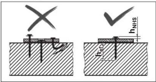
Do not insert a nail on top of one that has already been inserted. This could cause the nail to deform, the nails could become jammed or the power tool could move in an uncontrolled manner.
text_image
X hNHS h_effCheck whether the nails have been inserted correctly. For fastening to be secure, they must sit neither too high nor too low nor be bent.
text_image
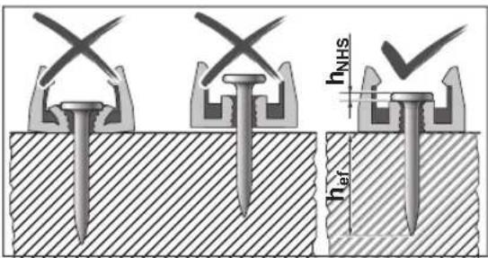
hNHS hefGNB 18V-40: When attaching fastening elements, also check that the nails have been set correctly.
If concrete is damaged by failed nails, it must be repaired in accordance with recognised rules.
text_image
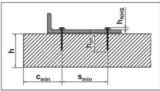
h hNHS h href cmin sminPlease find the following information in the documentation of Bosch nails at
http://www.bosch-pt.com:
- Nail head distance h NHS
- Effective embedment length h_ef
- Minimum thickness of concrete element h
- Minimum distance between two nails s min
- Minimum edge distance c min
- Recommended loads
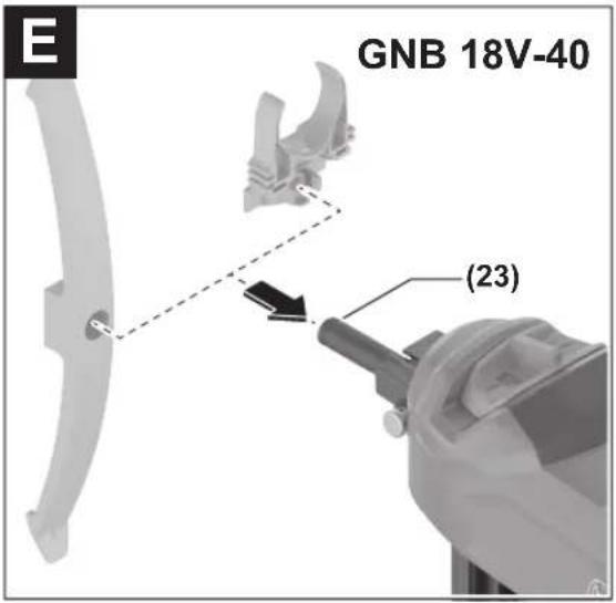
Attaching Fastening Elements (GNB 18V-40) (see figures E-F)
You can use the power tool to attach individual plastic or steel fastening elements to the substrate.
Examples of fastening elements:
Order number Description
| 1 600 A03 2G6 Pipe clamp 16 mm | |
| 1 600 A03 2G7 Pipe clamp 20 mm | |
| 1 600 A03 2G8 Pipe clamp 25 mm | |
| 1 600 A03 2G9 Pipe clamp 32 mm | |
| 1 600 A03 2GA Pipe clamp 40 mm | |
| 1 600 A03 2GB Cable bracket (one-sided) for 8 cables | |
| 1 600 A03 2GC Cable bracket (double-sided) for 16 cables | |
| 1 600 A03 2GD Cable holder for 20 cables | |
| 1 600 A03 2GE Cable holder for 40 cables | |
| 1 600 A03 2GF Cable tie holder | |
| 1 600 A03 2GG Cable ties 8-32 mm | |
| 1 600 A03 2GH Cable ties 16-63 mm |
You can find the complete range of Bosch-fastening elements at www.bosch-pt.com.
▶ Only use fastening elements that are recommended for your power tool by Bosch. The use of unauthorised fastening elements can damage the power tool and cause injury.
For plastic fastening elements, use the narrow contact element (23) (see figure E).
For steel fastening elements, use the standard contact element (17) (see figure F). Slide the magnet ring (24) sideways over the tip of the contact element so that it clicks into place.
Place a fastening element with the intended nail hole on the contact element (23) or the magnet ring (24).
▶ Only ever fit a single fastening element. Several elements on top of each other can lead to injuries or damage.
natural_image
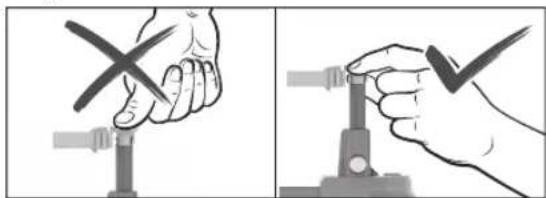
Two-step illustration showing a hand using a tool to press or adjust a cable, with no text or symbols present.▶ Always keep your hands to the side of the outlet when fitting the fastening element. Always point the outlet away from yourself or other persons. Do not press the contact element inwards. Keep your fingers away from the trigger. Unexpected triggering can cause a nail to be released, which can lead to injuries or damage to the power tool.
Press the contact element with the fastening element in place onto the substrate. Trigger the discharging procedure as usual.
Adjusting the Depth Stop
Set the fastening depth using the depth stop switch (20) so that the correct value for the nail head distance h_NHS is achieved.

Nail too deep: Press the depth stop switch (20) to the right.
If the nails are driven in too deep, use longer nails.
Nail not deep enough: Press the depth stop switch (20) to the left.
If the nails are not driven in deep enough, use shorter nails.
Clearing Jams/Resetting
Clear jams if the status display (2) lights up red or orange, or if the nails are no longer discharged correctly.
- Remove the rechargeable battery (10). Empty the magazine (12) and remove it. Remove the contact element (17).
- Check the magazine (12) and clear away dirt, residue and foreign objects.
- Check the contact element (17) and clear away nails, nail fragments, residue or foreign objects with the punch pin (21). When doing so, ensure that you do not damage the contact element.
- In sequence, re-insert the contact element (17), magazine (12) and battery (10).
- Press the button (15) on the magazine slider (14) and slide it towards the magazine opening until it engages.
- Switch on the power tool.
26 | English
- Press the Reset button (4) for 5 seconds until the status indicator (2) starts to flash.
- Press the contact element (17) against a wooden block or similar and press the trigger (6). By doing this, the motor can bring the firing pin into the correct position.
- If another fault is detected, the power tool does not return to normal operation. Instead, the other fault appears in the status display (2).
Removing the Supporting Leg
The supporting leg (13) allows the power tool to be aligned at a perpendicular angle on an even substrate. For work on an uneven substrate, you can remove the supporting leg (13). To do so, slide it behind the magazine (12).
Hanging Up the Power Tool
You can use the utility hook (25) to attach the switched-off power tool to a suitable suspension device. Using the screw supplied, screw the utility hook (25) to the housing of the power tool (see figure G).
- Check the utility hook (25) for damage or deformation. Do not use the utility hook (25) if it is damaged, deformed or no longer firmly secured to the power tool.
- Use the utility hook (25) to attach the power tool to a suspension device. To avoid damage or injury, the suspension device must not be attached above walkways or immediate work areas.
The utility hook is intended solely for the purpose of hanging the power tool, including fitted accessories.
▶ Never use the utility hook as a fall protection system.
Transport
For transport, switch off the power tool; especially when using ladders or moving in an unusual stance or posture. Lock the trigger with the unlocking switch (5). At the workplace, carry the power tool only by the handle (7) and with the trigger (6) released.
User interface
The user interface is used as follows:
- For switching the power tool on/off
- As the power tool status indicator
- As the battery charge indicator
- For resetting
Status indicators
| Colour of the status indicator (2) | Meaning/cause Solution | |
| Green The power tool is ready for use. - | ||
| Yellow Overheat protection: Motor or electronics are too warm. | Allow the power tool to cool down. If the motor and electronics are within the operating temperature, the power tool automatically returns to normal operation. | |
| Blue Protection against cold: The power tool is too cold. | Allow the power tool to reach the correct temperature in a warm environment. If the motor and electronics are within the operating temperature, the power tool automatically returns to normal operation. | |
| Red Jam detected: The firing pin cannot return to the correct position. | Clear the jam (see "Clearing Jams/Resetting", page 25). | |
| Orange The motor is blocked: The firing pin cannot be moved into the correct position. | Clear the jam (see "Clearing Jams/Resetting", page 25). | |
| Cyan Overcurrent protection: The motor is consuming too much power. | Check the power tool for jams or significant contamination and clear these (see "Clearing Jams/Resetting", page 25).If the error persists, contact an authorised after-sales service centre for Bosch power tools. | |
| Magenta (3 s long, green thereafter) | Maintenance is recommended: Error rate too high (e.g. bent nails or inadequate penetration depth) | Contact an authorised after-sales service centre for Bosch power tools. |
| White Electronics or sensor fault The power tool has been put into safe mode and cannot be used. Contact an authorised after-sales service centre for Bosch power tools. | ||
Battery charge indicator (3) Capacity
| 5 × continuous green light 80–100 % |
| 4 × continuous green light 60–80 % |
Battery charge indicator (3) Capacity
| 3 × continuous green light 40-60 % |
| 2 × continuous green light 20-40 % |
Battery charge indicator (3) Capacity
1 × continuous green light 5–20 %
1 × flashing green light 0–5 %
Maintenance and Service
Maintenance and Cleaning
▶ Before carrying out any work on the power tool (e.g. maintenance, tool change etc.), remove the battery
Rectifying Errors
from the power tool. There is risk of injury from unintentionally pressing the on/off switch.
▶ To ensure safe and efficient operation, always keep the power tool and the ventilation slots clean.
If the power tool has been stored for 2 years or longer without use, maintenance at an authorised after-sales service centre for Bosch power tools is recommended.
Problem Cause Corrective measure
| The power tool does not react. | No battery or empty battery inserted | Insert a charged battery. |
| Battery and/or power tool outside the operating temperature | Allow the battery and power tool to reach the correct operating temperature. | |
| Power tool not switched on | Switch on the power tool using the on/off button (1) on the user interface. | |
| No discharging procedure triggered | ≤ 2 nails in the magazine (12) Fill up the magazine (12). | |
| Trigger (6) locked | Press the unlocking switch (5) to the left to unlock the trigger (6). | |
| Work sequence incorrectly performed | Observe the correct work sequence: - Lift the contact element (17) from the substrate. - Release the trigger (6). - Press the contact element at a perpendicular angle on the substrate. - Press the trigger within 2 seconds after pressing on the contact element. | |
| Nail is not sitting deep enough. | Power tool too cold Allow the power tool to reach the correct operating temperature. | |
| Depth stop incorrectly set | Press the depth stop switch (20) to the left. | |
| Nail too long Use shorter nails. | Observe the suitable effective embedment length h_ef for your application. | |
| Substrate too hard Use alternative fastening methods, e.g. dowels. | ||
| Nail is sitting too deep. Depth stop incorrectly set | Press the depth stop switch (20) to the right. | |
| Nail too short Use longer nails. Observe the suitable effective embedment length h_ef for your application. | ||
| Substrate too soft Use alternative fastening methods, e.g. dowels. | ||
| Nail is bent or breaks. Power tool positioned at a slant on the substrate | Position the power tool perpendicular to the substrate. For an even substrate, use the supporting foot (13) to align it. | |
| Nail too long Use shorter nails. Observe the suitable effective embedment length h_ef for your application. | ||
| Substrate too hard For concrete with hard inclusions, try fastening at a different point. Otherwise, use alternative fastening methods, e.g. dowels. | ||
| Nail does not grip in steel. | Steel substrate too thin | Use alternative fastening methods, e.g. screwdriving. |
| Nail does not come out of contact element or contact element remains in pressed-in position. | Jamming in the contact element (e.g. due to foreign objects or dirt) | Clear the jam (see "Clearing Jams/Resetting", page 25). |
28 | Français
Problem Cause Corrective measure
Error rate too high Substrate too hard Use alternative fastening methods, e.g. dowels.
| Firing pin worn Have power tool repaired by an authorised after-sales service centre for Bosch power tools. | ||
| Nails do not slide into the magazine. | Magazine dirty | Clean the magazine (12), e.g. with a paintbrush. |
After-Sales Service and Application Service
Our after-sales service responds to your questions concerning maintenance and repair of your product as well as spare parts. You can find explosion drawings and information on spare parts at: www.bosch-pt.com
The Bosch product use advice team will be happy to help you with any questions about our products and their accessories.
In all correspondence and spare parts orders, please always include the 10-digit article number given on the nameplate of the product.
Great Britain
Robert Bosch Ltd. (B.S.C.)
P.O. Box 98
Broadwater Park
North Orbital Road
Denham Uxbridge
UB 9 5HJ
At www.bosch-pt.co.uk you can order spare parts or arrange the collection of a product in need of servicing or repair.
Tel. Service: (0344) 7360109
E-Mail: boschservicecentre@bosch.com
You can find further service addresses at:
www.bosch-pt.com/serviceaddresses
Transport
The recommended lithium-ion batteries are subject to legislation on the transport of dangerous goods. The user can transport the batteries by road without further requirements.
When the batteries are shipped by third parties (e.g. air transport or forwarding agency), special requirements on packaging and labelling (e.g. ADR regulations) must be met. A dangerous goods expert must be consulted when preparing the items for shipping.
Dispatch battery packs only when the housing is undamaged. Tape or mask off open contacts and pack up the battery in such a manner that it cannot move around in the packaging. Please also observe the possibility of more detailed national regulations.
Disposal
Power tools, rechargeable batteries, accessories and packaging should be sorted for environmental-friendly recycling.
Do not dispose of power tools and batteries/re-chargeable batteries into household waste!
Only for EU countries:
Power tools that are no longer suitable for use and defective or used batteries must be disposed of separately. Use the designated collection systems.
If disposed incorrectly, waste electrical and electronic equipment may have harmful effects on the environment and human health, due to the potential presence of hazardous substances.
Only for United Kingdom:
According to The Waste Electrical and Electronic Equipment Regulations 2013 (SI 2013/3113) (as amended) and the Waste Batteries and Accumulators Regulations 2009 (SI 2009/890) (as amended), products that are no longer usable must be collected separately and disposed of in an environmentally friendly manner.
Battery packs/batteries:
Li-ion:
Please observe the notes in the section on transport (see "Transport", page 28).
Français
natural_image
Two mechanical diagrams showing a tool interacting with a surface, one with a cross symbol and the other with a checkmark (no text or labels present)natural_image
Two mechanical diagrams showing a tool interacting with a surface, one with a cross mark and the other with a checkmark (no text or symbols present)natural_image
Two-step diagram showing hand holding a cross over a pipe, and clamping a cable with a checkmark (no text or symbols)Robert Bosch (France) S.A.S.
www.bosch-pt.com/serviceaddresses
Transport
natural_image
Two mechanical diagrams showing a tool interacting with a surface, one with a cross mark and the other with a checkmark (no text or symbols present)natural_image
Two mechanical diagrams showing a tool interacting with a surface, one with a cross mark and the other with a checkmark (no text or symbols present)natural_image
Two-step diagram showing hand holding a cross over a pipe, then adjusting a clamp (no text or symbols)Calle Robert Bosch No. 405
www.bosch-pt.com/serviceaddresses
Transporte
natural_image
Two mechanical diagrams showing a tool inserted into a workpiece, with no visible text or symbols.natural_image
Two mechanical diagrams showing a tool interacting with a surface, one marked with an X and the other with a checkmark (no text or symbols present)natural_image
Two-step diagram showing hand holding a cross over a pipe, then adjusting a clamp (no text or symbols)www.bosch-pt.com/serviceaddresses
Transporte
natural_image
Two mechanical diagrams showing a tool pressing into a workpiece, with no visible text or symbols.natural_image
Two mechanical diagrams showing a tool interacting with a surface, one with a cross mark and the other with a checkmark (no text or symbols present)natural_image
Two-step illustration showing a hand holding a tool with a cross mark and a close-up of the tool's tip (no text or symbols)www.bosch-pt.com/serviceaddresses
Trasporto
natural_image
Two mechanical diagrams showing a cutting tool on a base, with no visible text or symbols.natural_image
Two mechanical diagrams showing a tool interacting with a surface, one marked with an X and the other with a checkmark (no text or symbols present)text_image
h h_NHS h h_min S_minnatural_image
Illustration of a hand holding a tool with a cross mark, no text or symbols present
natural_image
Hand holding a tool with a checkmark, no visible text or symbolswww.bosch-pt.com/serviceaddresses
Vervoer
natural_image
Two mechanical diagrams showing a cutting tool on a base, with no visible text or symbols.natural_image
Two mechanical diagrams showing a tool pressing into a surface, with no visible text or symbols.text_image
X h_NHS h_NHSnatural_image
Illustration of a hand holding a tool with a cross mark, no text or symbols present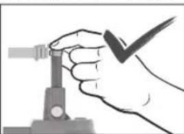
natural_image
Hand holding a tool with a checkmark, no visible text or symbolsBosch Service Center
Telegrafvej 3
2750 Ballerup
På www.bosch-pt.dk kan der online bestilles reservedele eller oprettes en reparations ordre.
Tlf. Service Center: 44898855
Fax: 44898755
E-Mail: vaerktoej@dk.bosch.com
www.bosch-pt.com/serviceaddresses
Transport
natural_image
Two mechanical diagrams showing a tool interacting with a surface, one marked with an X and the other with a checkmark (no text or symbols present)natural_image
Two mechanical diagrams showing a tool interacting with a surface, one marked with an X and the other with a checkmark (no text or symbols present)text_image
h_{NHS} h_{EF}natural_image
Two-step illustration showing hands using a tool to adjust or clamp a component, no text or symbols present.Bosch Service Center
Telegrafvej 3
2750 Ballerup
Danmark
Tel.: (08) 7501820 (inom Sverige)
Fax:(011)187691
www.bosch-pt.com/serviceaddresses
Transport
natural_image
Two mechanical diagrams showing a tool pressing into a surface, with no visible text or symbols.natural_image
Two mechanical diagrams showing a tool interacting with a surface, one marked with an X and the other with a checkmark (no text or symbols present)text_image
h h_NHS h h_min S_minnatural_image
Two-step illustration showing hand holding a tool with a cross mark and holding a clamp (no text or symbols)www.bosch-pt.com/serviceaddresses
Transport
natural_image
Two mechanical diagrams showing a tool interacting with a surface, one marked with an X and the other with a checkmark (no text or symbols present)natural_image
Two mechanical diagrams showing a cutting tool on a base, with no visible text or symbols.text_image
h_{NHS} h_{01}natural_image
Two-step illustration showing hand holding a tool and cutting a pipe into a clamp (no text or symbols)www.bosch-pt.com/serviceaddresses
Kuljetus
natural_image
Two mechanical diagrams showing a tool interacting with a surface, one marked with an X and the other with a checkmark (no text or symbols present)natural_image
Two mechanical diagrams showing a tool interacting with a surface, one marked with an X and the other with a checkmark (no text or symbols present)text_image
Diagram showing two hand positions: one holding a cross over a pipe, the other adjusting a clamp with a checkmark.www.bosch-pt.com/serviceaddresses
Μεταφορά
natural_image
Two mechanical diagrams showing a tool interacting with a surface, one marked with an X and the other with a checkmark (no text or symbols present)natural_image
Two mechanical diagrams showing a tool pressing into a workpiece, with no visible text or symbols.natural_image
Two-step illustration showing hand holding a tool with a cross mark, next to a close-up of the tool's tip (no text or symbols)www.bosch-pt.com/serviceaddresses
Nakliye
natural_image
Two mechanical diagrams showing a tool interacting with a surface, one with a cross mark and the other with a checkmark (no text or symbols present)natural_image
Two mechanical diagrams showing a tool pressing into a surface, with no visible text or symbols.natural_image
Illustration of a hand holding a cross over a pipe with a tool, no text or symbols present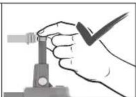
natural_image
Hand holding a small mechanical component with a checkmark (no text or symbols visible)Robert Bosch Sp. z o.o.
natural_image
Two mechanical diagrams showing a tool interacting with a surface, one marked with an X and the other with a checkmark (no text or symbols present)natural_image
Two mechanical diagrams showing a tool interacting with a surface, one with a cross mark and the other with a checkmark (no text or symbols present)natural_image
Two-step illustration showing a hand holding a tool with a cross mark and a tool inserted into a clip (no text or symbols)Bosch Service Center PT
K Vápence 1621/16
692 01 Mikulov
www.bosch-pt.com/serviceaddresses
Přeprava
natural_image
Two mechanical diagrams showing a tool interacting with a surface, one marked with an X and the other with a checkmark (no text or symbols present)natural_image
Two mechanical diagrams showing a tool interacting with a surface, one marked with an X and the other with a checkmark (no text or symbols present)text_image
h h_NHS h_refnatural_image
Illustration of a hand holding a tool with a cross mark, no text or symbols present
natural_image
Hand holding a tool with a checkmark, no visible text or symbolswww.bosch-pt.com/serviceaddresses
Transport
natural_image
Two mechanical diagrams showing a tool interacting with a surface, one marked with an X and the other with a checkmark (no text or symbols present)natural_image
Two mechanical diagrams showing a tool pressing into a surface, with no visible text or symbols.natural_image
Illustration of a hand holding a tool with a cross mark, no text or symbols present
natural_image
Hand holding a tool with a checkmark, no visible text or symbolswww.bosch-pt.com/serviceaddresses
Szállítás
natural_image
Two mechanical diagrams showing a tool interacting with a surface, one with a cross mark and the other with a checkmark (no text or symbols present)natural_image
Two mechanical diagrams showing a tool interacting with a surface, one with a cross mark and the other with a checkmark (no text or symbols present)natural_image
Illustration of a hand using a tool to cut a black X-shaped object, no text or symbols present
natural_image
Hand holding a tool with a checkmark, no visible text or symbolswww.bosch-pt.com/serviceaddresses
natural_image
Two mechanical diagrams showing a tool interacting with a surface, one marked with an X and the other with a checkmark (no text or symbols present)natural_image
Two mechanical diagrams showing a tool interacting with a surface, one marked with an X and the other with a checkmark (no text or symbols present)natural_image
Illustration of a hand holding a tool with a crossed-out X mark (no text or symbols)
natural_image
Hand holding a tool with a checkmark, no visible text or symbolsnatural_image
Two mechanical diagrams showing a tool interacting with a surface, one marked with an X and the other with a checkmark (no text or symbols present)230|Қазақ
natural_image
Two mechanical diagrams showing a tool interacting with a surface, one marked with an X and the other with a checkmark (no text or symbols present)natural_image
Illustration of a hand using a tool to cut a cross-shaped object, no text or symbols present
natural_image
Hand holding a tool with a checkmark (no text or symbols visible)www.bosch-pt.com/serviceaddresses
natural_image
Two mechanical diagrams showing a tool interacting with a surface, one marked with an X and the other with a checkmark (no text or symbols present)natural_image
Two mechanical diagrams showing a tool interacting with a surface, one with a cross mark and the other with a checkmark (no text or symbols present)natural_image
Illustration of a hand using a tool to cut a black X-shaped object (no text or symbols present)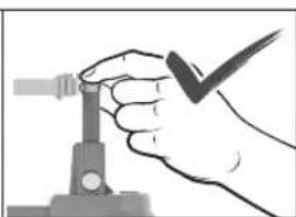
natural_image
Hand holding a tool with a checkmark, no visible text or symbolsService scule electrice
Strada Horia Măcelariu Nr. 30-34, sector 1
013937 Bucureşti
www.bosch-pt.com/serviceaddresses
Transport
natural_image
Two mechanical diagrams showing a tool interacting with a surface, one marked with an X and the other with a checkmark (no text or symbols present)natural_image
Two mechanical diagrams showing a tool interacting with a surface, one marked with an X and the other with a checkmark (no text or symbols present)natural_image
Two-step illustration showing a hand using a tool to press or adjust a cable, with no text or symbols present.Service scule electrice
Strada Horia Măcelariu Nr. 30–34, sector 1
013937 Bucureşti, România
www.bosch-pt.com/bg/bg/
www.bosch-pt.com/serviceaddresses
Транспортиране
natural_image
Two mechanical diagrams showing a tool interacting with a surface, one with a cross mark and the other with a checkmark (no text or symbols present)natural_image
Two mechanical diagrams showing a tool interacting with a surface, one with a cross mark and the other with a checkmark (no text or symbols present)text_image
Diagram showing two-step hand-drawn instructions for using a tool to adjust or clamp a component, with a magnified cross symbol indicating the process.www.bosch-pt.com/serviceaddresses
Транспорт
natural_image
Two mechanical diagrams showing a tool inserted into a workpiece, with no visible text or symbols.natural_image
Two mechanical diagrams showing a tool interacting with a surface, one marked with an X and the other with a checkmark (no text or symbols present)natural_image
Illustration of a hand using a tool to cut a cross symbol (no text or symbols present)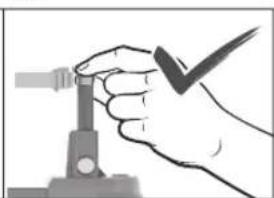
natural_image
Hand holding a tool with a checkmark, no visible text or symbols| Dritë e vazhdueshme 5× jeshile 80–100 % |
| Dritë e vazhdueshme 4× jeshile 60–80 % |
| Dritë e vazhdueshme 3× jeshile 40–60 % |
| Dritë e vazhdueshme 2× jeshile 20–40 % |
| Dritë e vazhdueshme 1× jeshile 5–20 % |
| Dritë pulsuese 1× jeshile 0–5 % |
www.bosch-pt.com/serviceaddresses
Transporti
natural_image
Two mechanical diagrams showing a tool interacting with a surface, one with cross marks and the other with checkmark (no text or symbols)Nikad nemojte držati električni alat pod oštrim uglom u odnosu na podlogu. Električni alat mora da stoji u vertikalnom položaju u odnosu na podlogu. Na podlozi ne smeje da se nalazi nečistoća.
Nemojte deaktivirati ili uklanjati kontaktni element. Kontaktni element služi kao sigurnosni mehanizam za smanjivanje rizika od nehotičnog aktiviranja. Deaktiviranje ove komponente može da dovede do nehotičnog aktiviranja.
Električni alat koristite samo kada kontaktni element pravilno funkcioniše. Ako je kontaktni element neispravan, električni alat može neočekivano da se pokrene.
Uvek prvo stavite eksere u magacin električnog alata, pre nego što stavite akumulator. Tako ćete smanjiti rizik slučajnog okidanja eksera i povrede sebe ili drugih osoba.
Nikad nemojte okidati eksere u blizini zapaljivih materijala. Kod pojedinih vrsta eksera tokom okidanja mogu nastati varnice iz kontaktnog elementa.
Ekser nemojte zakucavati na drugi ekser. To može dovesti do skretanja eksera ili neočekivane reakcije električnog alata.
Opis proizvoda i primene

natural_image
Two mechanical diagrams showing a tool interacting with a surface, one marked with an X and the other with a checkmark (no text or symbols present)natural_image
Two-step illustration showing a hand holding a tool with a cross mark and a tool inserted into a clip (no text or symbols)Prilikom postavljanja elementa za pričvršćivanje uvek držite sa strane od otvora. Uvek usmerite otvor dalje od sebe i drugih osoba. Nemojte pritiskati kontaktni element ka unutra. Držite prste dalje od okidača. Usled nehotičnog okidanja može da se ispusti ekser, što može da dovede do povreda ili oštećenja električnog alata.
Pritisnite kontaktni element sa postavljenim elementom za pričvršćivanje na podlogu. Pokrenite postupak zakivanja na uobičajeni način.
www.bosch-pt.com/serviceaddresses
Transport
Preporučeni litijum-jonski akumulatori podležu zahtevima propisa o opasnim materijama. Korisnik može bez dodatnih uslova transportovati akumulatore na drumu.
Kod slanja preko trećih lica (na primer vazdušnim transportom ili špedicijom) mora se obratiti pažnja na posebne zahteve u pogledu pakovanja i označavanja. Tada se kod pripreme paketa za slanje mora pozvati stručnjak za opasne materije.
Akumulatorske baterije šaljite samo ako kućište nije oštećeno. Odlepite otvorene kontakte i upakujte akumulatorsku bateriju tako, da se ne pokreće u paketu. Molimo da obratite pažnju na eventualne dalje nationalne propise.
Uklanjanje dubreta
Električne alate, akumulacione baterije, pribor i pakovanja treba predati na reciklažu koja je u skladu sa zaštitom životne sredine.

Ne bacajte električne alate i akumulatore/baterije u kućno djubre!
Samo za EU-zemlje:
natural_image
Two mechanical diagrams showing a tool pressing into a workpiece, with no visible text or symbols.natural_image
Two mechanical diagrams showing a tool interacting with a surface, one marked with an X and the other with a checkmark (no text or symbols present)natural_image
Two-step illustration showing hand holding a tool with a cross, and clamping the tool with a checkmark (no text or symbols)www.bosch-pt.com/serviceaddresses
Transport
natural_image
Two mechanical diagrams showing a tool interacting with a surface, one with a cross mark and the other with a checkmark (no text or symbols present)Nikada nemojte držati električni alat pod oštrim kutom u odnosu na površinu. Električni alat mora stajati okomito na podlogu. Na podlozi ne smije biti prljavštine.
▶ Nemojte deaktivirati niti ukloniti kontaktni element. Kontaktni element služi kao sigurnosni mehanizam za smanjenje rizika od nehotičnog aktiviranja. Deaktiviranje ove komponente može uzrokovati nehotično aktiviranje.
▶ Upotrebljavajte električni alat samo ako kontaktni element ispravno radi. Ako je kontaktni element neispravan, električni alat može se neočekivano aktivirati.
Uvijek napunite čavle u spremnik električnog alata prije umetanja aku-baterije. Time se smanjuje rizik da nehotično zabijete čavao i da ozlijedite sebe ili druge osobe.
Nikada nemojte zabijati čavle u blizini zapaljivih materijala. Kod nekih vrsta čavala iskre mogu izbijati iz kontaktnog elementa tijekom zabijanja.
▶ Nemojte zabijati čavao na drugi čavao. To bi moglo uzrokovati otklon čavla ili neočekivanu reakciju električnog alata.
Opis proizvoda i radova

Treba pročitati sve sigurnosne napomene i upute. Propusti do kojih može doći uslijed nepridržavanja sigurnosnih napomena i uputa mogu uzrokovati električni udar, požar i/ili teške ozljede.
natural_image
Two mechanical diagrams showing a tool interacting with a surface, one marked with an X and the other with a checkmark (no text or symbols present)natural_image
Two-step illustration showing a hand holding a tool with a cross mark and a tool inserted into a clip (no text or symbols)www.bosch-pt.com/serviceaddresses
Transport
Naeluti ohutusalane teave
natural_image
Two mechanical diagrams showing a tool interacting with a surface, one with a cross mark and the other with a checkmark (no text or symbols present)natural_image
Two mechanical diagrams showing a tool interacting with a surface, one marked with an X and the other with a checkmark (no text or symbols present)natural_image
Two-step illustration showing a hand holding a tool with a cross mark and a clamp, no text or symbols present.www.bosch-pt.com/serviceaddresses
Transport
natural_image
Two mechanical diagrams showing a cutting tool on a base, with no visible text or symbols.natural_image
Two mechanical diagrams showing a tool interacting with a surface, one marked with an X and the other with a checkmark (no text or symbols present)text_image
h h_NHS h_refnatural_image
Illustration of a hand using a tool to cut a black X-shaped mark on a pipe (no text or symbols)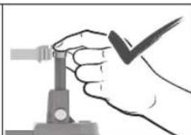
natural_image
Hand holding a tool with a checkmark, no visible text or symbolswww.bosch-pt.com/serviceaddresses
Transportēšana
natural_image
Two mechanical diagrams showing a tool pressing into a surface, with no visible text or symbols.natural_image
Two mechanical diagrams showing a tool pressing into a workpiece, with no visible text or symbols.text_image
h_{NHS} h_{ET}natural_image
Two-step illustration showing hand holding a tool with a cross mark, next to a close-up of the tool's tip (no text or symbols)www.bosch-pt.com/serviceaddresses
Transportavimas
natural_image
Two mechanical diagrams showing a tool interacting with a surface, one marked with an X and the other with a checkmark (no text or symbols present)natural_image
Two mechanical diagrams showing a tool interacting with a surface, one with a cross mark and the other with a checkmark (no text or symbols present)text_image
h hNHS h effnatural_image
Illustration of a hand using a tool to cut a black X-shaped object on a pipe (no text or symbols)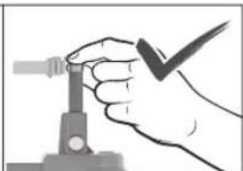
natural_image
Hand holding a tool with a checkmark, no visible text or symbolswww.bosch-pt.com/serviceaddresses
운반
natural_image
Two mechanical diagrams showing a tool interacting with a surface, one marked with an X and the other with a checkmark (no text or symbols present)natural_image
Two mechanical diagrams showing a tool interacting with a surface, one with a cross mark and the other with a checkmark (no text or symbols present)natural_image
Two-step illustration showing hand holding a tool with a cross mark, next to a close-up of the same hand using a clamp (no text or symbols)Robert Bosch Morocco SARL
www.bosch-pt.com/serviceaddresses
376|عربي
natural_image
Two mechanical diagrams showing a tool pressing into a surface, with no visible text or symbols.• إ Campaigns Marketing نكّه
انند دست ها، پاها
از میغ کوب، تمامی
و سیم عای پنهان
دیده باشد ويا از
natural_image
Two mechanical diagrams showing a tool interacting with a surface, one marked with an X and the other with a checkmark (no text or symbols present)text_image
kirin kirin hNHS he(دو طرفه) برای
16 كابل
www.bosch-pt.com/serviceaddresses
CALL DSTKAT
Declaration of Conformity
Cordless nailer Article number
GNB 18V-38
3 601 JL7 000
GNB 18V-40
3 601 JL7 001
We declare under our sole responsibility that the stated products comply with all applicable provisions of the regulations listed below and are in conformity with the following standards.
Technical file at: Robert Bosch Ltd. (PT/SOP-GB), Broadwater Park, North Orbital Road, Uxbridge UB9 5HJ, United Kingdom
The Supply of Machinery (Safety) Regulations 2008
The Electromagnetic Compatibility Regulations 2016
The Restriction of the Use of Certain Hazardous Substances in
Electrical and Electronic Equipment Regulations 2012
EN 60745-1:2009+A11:2010
EN 60745-2-16:2010
EN IEC 55014-1:2021
EN IEC 55014-2:2021
EN IEC 63000:2018

BOSCH
Vonjy Rajakoba
Managing Director - Bosch UK
Robert Bosch Power Tools GmbH, 70538 Stuttgart, Germany represented (in terms of the above regulations) by
Robert Bosch Limited, Broadwater Park, North Orbital Road, Uxbridge UB9 5HJ, United Kingdom
text_image
Damm JohmyMartin Sibley
Head of Sales Operations and Aftersales

text_image
lunla dlyRobert Bosch Ltd. Broadwater Park, North Orbital Road, Uxbridge UB9 5HJ, United Kingdom, as authorised representative acting on behalf of Robert Bosch Power Tools GmbH, 70538 Stuttgart, Germany
Place of issue: Uxbridge Date of issue: 03/06/2024