GNF 35 CA Professional - Stapler BOSCH - Free user manual and instructions
Find the device manual for free GNF 35 CA Professional BOSCH in PDF.

| Brand | Bosch |
| Model | GNF 35 CA Professional |
| Category | Grooving/milling machine |
| Product type | Grooving/milling machine for cutting and grooving of mineral materials |
| Nominal power input | 1400 W |
| Output power | 750 W |
| No-load speed | 9300 rpm |
| Max. diamond wheel diameter | 150 mm |
| Groove depth | 0 – 35 mm (adjustable) |
| Groove width | 7 – 39 mm (depending on wheels and spacers) |
| Power supply | 230 V, mains, 50/60 Hz |
| Weight (EPTA) | 4.7 kg |
| Protection class | II (double insulation) |
| Sound pressure level | 102 dB(A) |
| Sound power level | 113 dB(A) |
| Vibration (total value) | 4.0 m/s² (uncertainty K=1.5 m/s²) |
| Main functions | Dry cutting and grooving of reinforced concrete, masonry, road surfaces |
| Maintenance and cleaning | Clean the ventilation slots regularly; after use, disassemble and clean the clamping devices |
| Safety | Read warnings; wear PPE (goggles, FFP2 mask, gloves); use protective device |
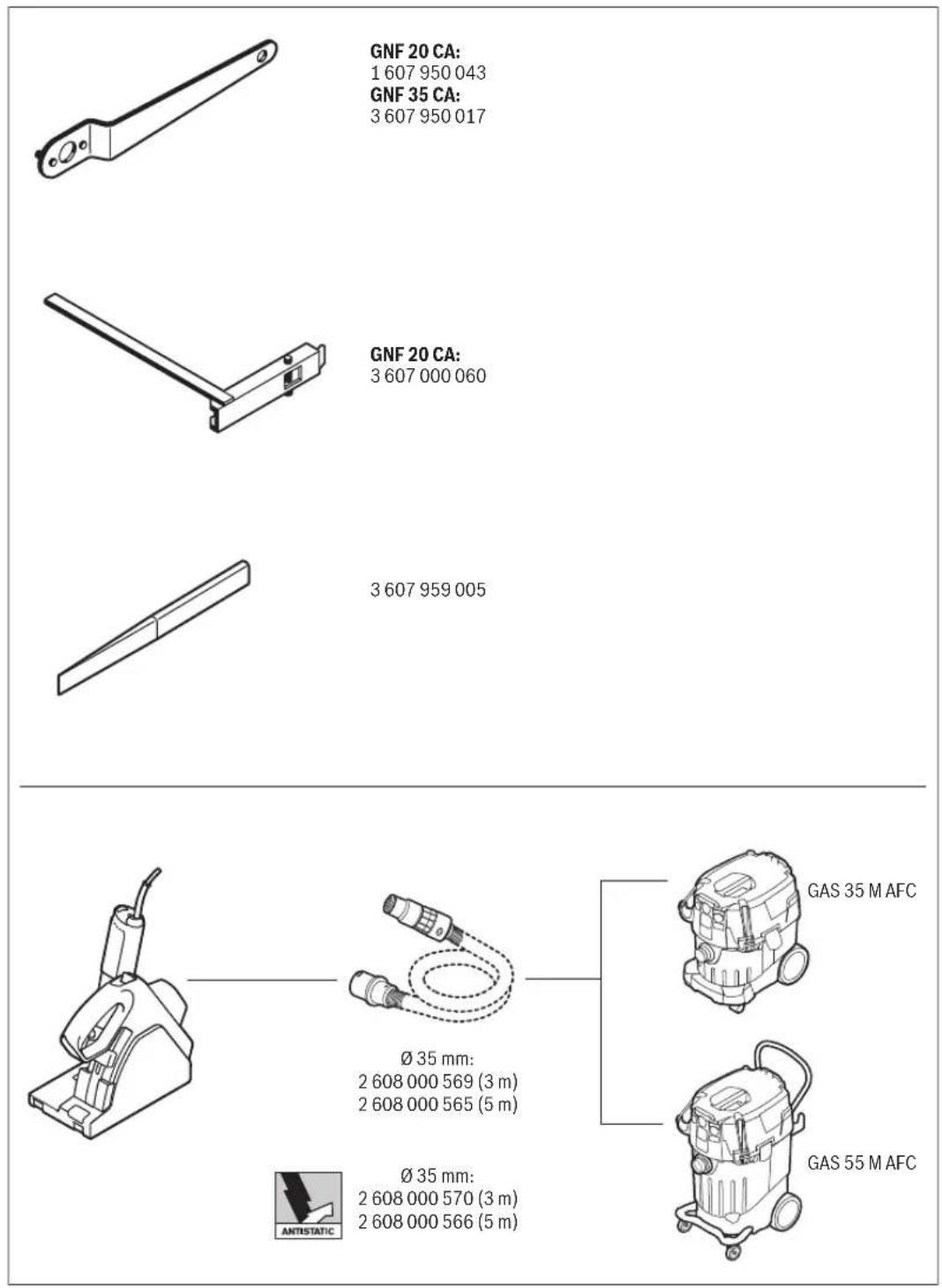
| Spare parts | Tool flange (3 609 202 039), washers (4 mm: 3 609 202 041, 6 mm: 3 609 202 042), nut (3 609 202 040) |
| Repairability | Bosch after-sales service; repair by qualified personnel with original parts |
| Article number | 0 601 621 7.. |
| Intended use | Cutting/grooving of mineral materials without water |
Frequently Asked Questions - GNF 35 CA Professional BOSCH
User questions about GNF 35 CA Professional BOSCH
0 question about this device. Answer the ones you know or ask your own.
Ask a new question about this device
Download the instructions for your Stapler in PDF format for free! Find your manual GNF 35 CA Professional - BOSCH and take your electronic device back in hand. On this page are published all the documents necessary for the use of your device. GNF 35 CA Professional by BOSCH.
USER MANUAL GNF 35 CA Professional BOSCH
OBJ_BUCH-126-003.book Page 1 Tuesday, August 9, 2016 2:59 PM
natural_image
Illustration of a handheld electronic device with a power tool and base (no text or symbols visible)Robert Bosch Power Tools GmbH
70538 Stuttgart
Germany
www.bosch-pt.com
1609 92A 2PP (2014.03) O / 262 EURO

GNF Professional
20 CA|35 CA

BOSCH
natural_image
Technical line drawing of a mechanical device with labeled component (no text or symbols present)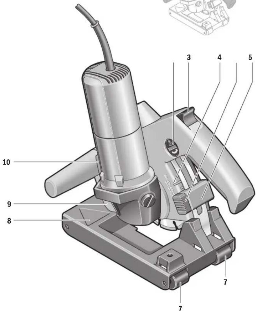
GNF 20 CA


4
5


OBJ_BUCH-126-003.book Page 6 Tuesday, August 9, 2016 2:52 PM
Deutsch | 7
Deutsch
Sicherheitshinweise
Executive Vice President Engineering
Head of Product Certification PT/ETM9

Robert Bosch Power Tools GmbH 70538 Stuttgart, GERMANY Stuttgart. 01.01.2017
Montage
Staubabsaugung
natural_image
Mechanical assembly diagram showing a Bosch printer on a workbench (no text or symbols visible)General Power Tool Safety Warnings
WARNING
Read all safety warnings and all instructions. Failure to follow the warnings
and instructions may result in electric shock, fire and/or serious injury.
Save all warnings and instructions for future reference.
The term "power tool" in the warnings refers to your mains-operated (corded) power tool or battery-operated (cordless) power tool.
Work area safety
- Keep work area clean and well lit. Cluttered or dark areas invite accidents.
▶ Do not operate power tools in explosive atmospheres, such as in the presence of flammable liquids, gases or dust. Power tools create sparks which may ignite the dust or fumes.
▶ Keep children and bystanders away while operating a power tool. Distractions can cause you to lose control.
Electrical safety
▶ Power tool plugs must match the outlet. Never modify the plug in any way. Do not use any adapter plugs with earthed (grounded) power tools. Unmodified plugs and matching outlets will reduce risk of electric shock.
▶ Avoid body contact with earthed or grounded surfaces, such as pipes, radiators, ranges and refrigerators. There is an increased risk of electric shock if your body is earthed or grounded.
▶ Do not expose power tools to rain or wet conditions. Water entering a power tool will increase the risk of electric shock.
▶ Do not abuse the cord. Never use the cord for carrying, pulling or unplugging the power tool. Keep cord away from heat, oil, sharp edges and moving parts. Damaged or entangled cords increase the risk of electric shock.
When operating a power tool outdoors, use an extension cord suitable for outdoor use. Use of a cord suitable for outdoor use reduces the risk of electric shock.
▶ If operating a power tool in a damp location is unavoidable, use a residual current device (RCD) protected supply. Use of an RCD reduces the risk of electric shock.
Personal safety
Stay alert, watch what you are doing and use common sense when operating a power tool. Do not use a power tool while you are tired or under the influence of drugs, alcohol or medication. A moment of inattention while operating power tools may result in serious personal injury.
▶ Use personal protective equipment. Always wear eye protection. Protective equipment such as dust mask, non-skid safety shoes, hard hat, or hearing protection used for appropriate conditions will reduce personal injuries.
▶ Prevent unintentional starting. Ensure the switch is in the off-position before connecting to power source and/or battery pack, picking up or carrying the tool. Carrying power tools with your finger on the switch or energising power tools that have the switch on invites accidents.
Remove any adjusting key or wrench before turning the power tool on. A wrench or a key left attached to a rotating part of the power tool may result in personal injury.


16 | English
Do not overreach. Keep proper footing and balance at all times. This enables better control of the power tool in unexpected situations.
▶ Dress properly. Do not wear loose clothing or jewellery. Keep your hair, clothing and gloves away from moving parts. Loose clothes, jewellery or long hair can be caught in moving parts.
If devices are provided for the connection of dust extraction and collection facilities, ensure these are connected and properly used. Use of dust collection can reduce dust-related hazards.
Power tool use and care
▶ Do not force the power tool. Use the correct power tool for your application. The correct power tool will do the job better and safer at the rate for which it was designed.
▶ Do not use the power tool if the switch does not turn it on and off. Any power tool that cannot be controlled with the switch is dangerous and must be repaired.
▶ Disconnect the plug from the power source and/or the battery pack from the power tool before making any adjustments, changing accessories, or storing power tools. Such preventive safety measures reduce the risk of starting the power tool accidentally.
▶ Store idle power tools out of the reach of children and do not allow persons unfamiliar with the power tool or these instructions to operate the power tool. Power tools are dangerous in the hands of untrained users.
- Maintain power tools. Check for misalignment or binding of moving parts, breakage of parts and any other condition that may affect the power tool's operation. If damaged, have the power tool repaired before use. Many accidents are caused by poorly maintained power tools.
▶ Keep cutting tools sharp and clean. Properly maintained cutting tools with sharp cutting edges are less likely to bind and are easier to control.
▶ Use the power tool, accessories and tool bits etc. in accordance with these instructions, taking into account the working conditions and the work to be performed. Use of the power tool for operations different from those intended could result in a hazardous situation.
Service
▶ Have your power tool serviced by a qualified repair person using only identical replacement parts. This will ensure that the safety of the power tool is maintained.
Cut-off machine safety warnings
The guard provided with the tool must be securely attached to the power tool and positioned for maximum safety, so the least amount of wheel is exposed towards the operator. Position yourself and bystanders away from the plane of the rotating wheel. The guard helps to protect operator from broken wheel fragments and accidental contact with wheel.
▶ Use only bonded reinforced or diamond cut-off wheels for your power tool. Just because an accessory can be at-
tached to your power tool, it does not assure safe operation.
The rated speed of the accessory must be at least equal to the maximum speed marked on the power tool. Accessories running faster than their rated speed can break and fly apart.
Wheels must be used only for recommended applications. For example: do not grind with the side of cut-off wheel. Abrasive cut-off wheels are intended for peripheral grinding, side forces applied to these wheels may cause them to shatter.
▶ Always use undamaged wheel flanges that are of correct diameter for your selected wheel. Proper wheel flanges support the wheel thus reducing the possibility of wheel breakage.
The outside diameter and the thickness of your accessory must be within the capacity rating of your power tool. Incorrectly sized accessories cannot be adequately guarded or controlled.
The arbour size of wheels and flanges must properly fit the spindle of the power tool. Wheels and flanges with arbour holes that do not match the mounting hardware of the power tool will run out of balance, vibrate excessively and may cause loss of control.
Do not use damaged wheels. Before each use, inspect the wheels for chips and cracks. If power tool or wheel is dropped, inspect for damage or install an undamaged wheel. After inspecting and installing the wheel, position yourself and bystanders away from the plane of the rotating wheel and run the power tool at maximum no load speed for one minute. Damaged wheels will normally break apart during this test time.
▶ Wear personal protective equipment. Depending on application, use face shield, safety goggles or safety glasses. As appropriate, wear dust mask, hearing protectors, gloves and shop apron capable of stopping small abrasive or workpiece fragments. The eye protection must be capable of stopping flying debris generated by various operations. The dust mask or respirator must be capable of filtrating particles generated by your operation. Prolonged exposure to high intensity noise may cause hearing loss.
▶ Keep bystanders a safe distance away from work area. Anyone entering the work area must wear personal protective equipment. Fragments of workpiece or of a broken accessory may fly away and cause injury beyond immediate area of operation.
Hold the power tool by insulated gripping surfaces only, when performing an operation where the cutting accessory may contact hidden wiring or its own cord. Cutting accessory contacting a "live" wire may make exposed metal parts of the power tool "live" and could give the operator an electric shock.
▶ Position the cord clear of the spinning accessory. If you lose control, the cord may be cut or snagged and your hand or arm may be pulled into the spinning wheel.


English | 17
▶ Never lay the power tool down until the accessory has come to a complete stop. The spinning wheel may grab the surface and pull the power tool out of your control.
▶ Do not run the power tool while carrying it at your side. Accidental contact with the spinning accessory could snag your clothing, pulling the accessory into your body.
▶ Regularly clean the power tool's air vents. The motor's fan will draw the dust inside the housing and excessive accumulation of powdered metal may cause electrical hazards.
▶ Do not operate the power tool near flammable materials. Sparks could ignite these materials.
▶ Do not use accessories that require liquid coolants. Using water or other liquid coolants may result in electrocution or shock.
Kickback and related warnings
▶ Kickback is a sudden reaction to a pinched or snagged rotating wheel. Pinching or snagging causes rapid stalling of the rotating wheel which in turn causes the uncontrolled power tool to be forced in the direction opposite of the wheel's rotation at the point of the binding.
For example, if an abrasive wheel is snagged or pinched by the workpiece, the edge of the wheel that is entering into the pinch point can dig into the surface of the material causing the wheel to climb out or kick out. The wheel may either jump toward or away from the operator, depending on direction of the wheel's movement at the point of pinching. Abrasive wheels may also break under these conditions.
Kickback is the result of power tool misuse and/or incorrect operating procedures or conditions and can be avoided by taking proper precautions as given below.
- Maintain a firm grip on the power tool and position your body and arm to allow you to resist kickback forces. Always use auxiliary handle, if provided, for maximum control over kickback or torque reaction during start-up. The operator can control torque reactions or kickback forces, if proper precautions are taken.
▶ Never place your hand near the rotating accessory. Accessory may kickback over your hand.
Do not position your body in line with the rotating wheel. Kickback will propel the tool in direction opposite to the wheel's movement at the point of snagging.
▶ Use special care when working corners, sharp edges, etc. Avoid bouncing and snagging the accessory. Corners, sharp edges or bouncing have a tendency to snag the rotating accessory and cause loss of control or kickback.
▶ Do not attach a saw chain, woodcarving blade, segmented diamond wheel with a peripheral gap greater than 10 mm or toothed saw blade. Such blades create frequent kickback and loss of control.
Do not "jam" the wheel or apply excessive pressure. Do not attempt to make an excessive depth of cut. Over-stressing the wheel increases the loading and susceptibility to twisting or binding of the wheel in the cut and the possibility of kickback or wheel breakage.
When wheel is binding or when interrupting a cut for any reason, switch off the power tool and hold the power tool motionless until the wheel comes to a complete stop. Never attempt to remove the wheel from the cut while the wheel is in motion otherwise kickback may occur. Investigate and take corrective action to eliminate the cause of wheel binding.
▶ Do not restart the cutting operation in the workpiece. Let the wheel reach full speed and carefully re-enter the cut. The wheel may bind, walk up or kickback if the power tool is restarted in the workpiece.
▶ Support panels or any oversized workpiece to minimize the risk of wheel pinching and kickback. Large workpieces tend to sag under their own weight. Supports must be placed under the workpiece near the line of cut and near the edge of the workpiece on both sides of the wheel.
▶ Use extra caution when making a "pocket cut" into existing walls or other blind areas. The protruding wheel may cut gas or water pipes, electrical wiring or objects that can cause kickback.
Additional safety warnings

Wear safety goggles.
▶ Use clamps or another practical way to secure and support the workpiece to a stable platform. Holding the work by your hand or against the body leaves it unstable and may lead to loss of control.
▶ Wear hearing protection, safety goggles, dust mask and gloves. As dust mask, use at least a particle filtering half mask of filter class FFP 2.
▶ Use suitable detectors to determine if utility lines are hidden in the work area or call the local utility company for assistance. Contact with electric lines can lead to fire and electric shock. Damaging a gas line can lead to explosion. Penetrating a water line causes property damage or may cause an electric shock.
▶ Do not touch the cutting disc after working before it has cooled. The cutting disc becomes very hot while working.
When working with the machine, always hold it firmly with both hands and provide for a secure stance. The power tool is guided more secure with both hands.
Products sold in GB only: Your product is fitted with a BS 1363/A approved electric plug with internal fuse (ASTA approved to BS 1362).
If the plug is not suitable for your socket outlets, it should be cut off and an appropriate plug fitted in its place by an authorised customer service agent. The replacement plug should have the same fuse rating as the original plug.
The severed plug must be disposed of to avoid a possible shock hazard and should never be inserted into a mains socket elsewhere.
Products sold in AUS and NZ only: Use a residual current device (RCD) with a rated residual current of 30 mA or less.


18 | English
Product Description and Specifications

Read all safety warnings and all instructions. Failure to follow the warnings and instructions may result in electric shock, fire and/or serious injury.
While reading the operating instructions, unfold the graphics page for the machine and leave it open.
Intended Use
In conjunction with a dust-category M vacuum cleaner and with firm support of the cutting guide, the machine is intended to cut or slot mainly mineral materials such as reinforced concrete, brickwork and road surfaces without the use of water.
Product Features
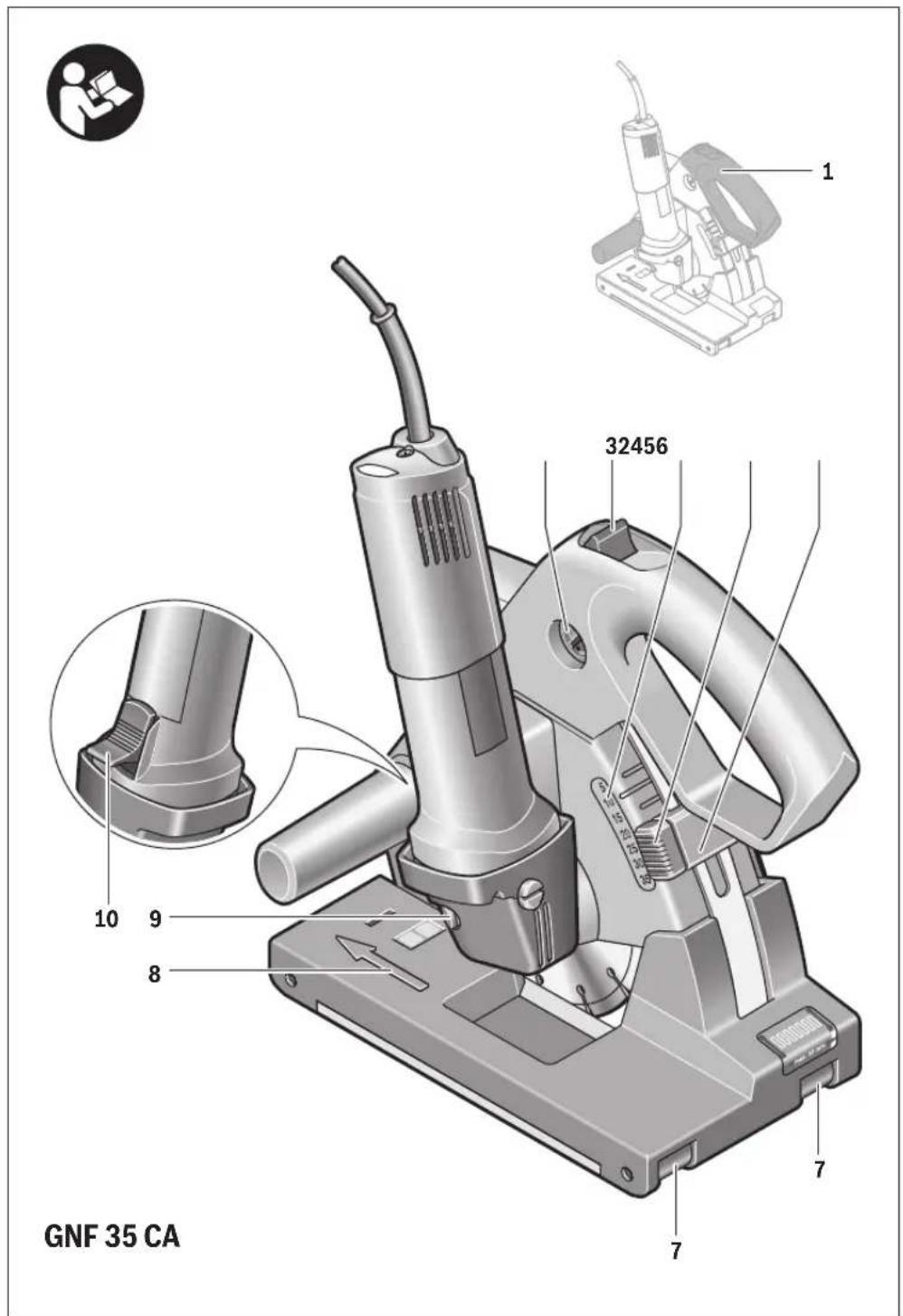
The numbering of the product features refers to the illustration of the machine on the graphics page.
1 Handle (insulated gripping surface)
2 Release lock
3 Release button for the cutting unit
4 Cutting-depth scale
5 Button for depth stop adjustment
6 Depth stop
7 Chaser rollers
8 Working-direction arrow
9 Spindle lock button
10 On/Off switch
11 Service indicator(GNF 35 CA)
12 Vacuum hose*
13 Vacuum connection
14 Parallel guide(GNF 20 CA)*
15 Guide bolt for parallel guide (GNF 20 CA) *
16 Grinder spindle
17 Mounting flange
18 Diamond cutting disc*
19 Spacer discs
20 Clamping nut
21 Two-pin spanner for clamping nut*
22 Break-out tool*
23 Direction of rotation
*Accessories shown or described are not part of the standard delivery scope of the product. A complete overview of accessories can be found in our accessories program.
Technical Data
| Wall Chaser | GNF 20 CA | GNF 35 CA | |
| Article number | 06016125..06016217.. | ||
| Rated power input | W9001400 | ||
| Output power | W520750 | ||
| No-load speed | min^-1 | 93009300 | |
| Max. diameter for diamond cutting discs | mm115150 | ||
| Working with one diamond cutting disc | |||
| – Cutting discs width, min. | mm | 1.6 | 2.0 |
| – Cutting discs width, max. | mm | 2.2 | 2.5 |
| Working with two diamond cutting discs | |||
| – Cutting discs width, min. | mm | 2x1,6 | 2x2,0 |
| – Cutting discs width, max. | mm | 2x2,2 | 2x2,5 |
| Mounting bore | mm22.222.2 | ||
| Slot depth | mm0-200-35 | ||
| Slot width | mm7-237-39 | ||
| Weight according to EPTA-Procedure 01:2014 | kg | 3.4 | 4.7 |
| Protection class | ☐/II | ☐/II | |
| The values given are valid for a nominal voltage [U] of 230 V. For different voltages and models for specific countries, these values can vary. | |||
English | 19
Noise/Vibration Information
| GNF 20 CA | GNF 35 CA | ||
| Measured values determined according to EN 60745 (lime-sand brick). | |||
| Typically the A-weighted noise levels of the product are | |||
| Sound pressure level | dB(A) | 94 | 102 |
| Sound power level | dB(A) | 105 | 113 |
| Uncertainty K | dB | 3 | 3 |
| Wear hearing protection! | |||
| Vibration total values a_h (triax vector sum) and uncertainty K determined according to EN 60745: | |||
| a_h | m/s2 | =4.0 | =4.0 |
| K | m/s2 | =1.5 | =1.5 |
The vibration level given in this information sheet has been measured in accordance with a standardised test given in EN 60745 and may be used to compare one tool with another. It may be used for a preliminary assessment of exposure. The declared vibration emission level represents the main applications of the tool. However if the tool is used for different applications, with different accessories or insertion tools or is poorly maintained, the vibration emission may differ. This may significantly increase the exposure level over the total working period.
An estimation of the level of exposure to vibration should also take into account the times when the tool is switched off or when it is running but not actually doing the job. This may significantly reduce the exposure level over the total working period.
Identify additional safety measures to protect the operator from the effects of vibration such as: maintain the tool and the accessories, keep the hands warm, organisation of work patterns.
Declaration of Conformity

We declare under our sole responsibility that the product described under "Technical Data" is in conformity with the following standards or standardization documents: EN 60745, EN 50581 according to the provisions of the directives 2011/65/EU, 2014/30/EU, 2006/42/EC.
Technical file (2006/42/EC) at: Robert Bosch Power Tools GmbH, PT/ETM9, D-70538 Stuttgart
Henk Becker Executive Vice President Engineering Helmut Heinzelmann Head of Product Certification PT/ETM9

Robert Bosch Power Tools GmbH 70538 Stuttgart, GERMANY Stuttgart, 01.01.2017
Assembly
Dust Extraction
▶ Dusts from materials such as lead-containing coatings, some wood types, minerals and metal can be harmful to
one's health. Touching or breathing-in the dusts can cause allergic reactions and/or lead to respiratory infections of the user or bystanders.
Certain dusts, such as oak or beech dust, are considered as carcinogenic, especially in connection with wood-treatment additives (chromate, wood preservative). Materials containing asbestos may only be worked by specialists.
- As far as possible, use a dust extraction system suitable for the material.
- Provide for good ventilation of the working place.
- It is recommended to wear a P2 filter-class respirator. Observe the relevant regulations in your country for the materials to be worked.
▶ Prevent dust accumulation at the workplace. Dusts can easily ignite.
The vacuum cleaner must be approved for the extraction of masonry dust. Bosch provides suitable vacuum cleaners.
The machine can be plugged directly into the receptacle of a Bosch all-purpose vacuum cleaner with remote starting control. The vacuum cleaner starts automatically when the machine is switched on.
Place a vacuum hose 12 (accessory) onto the vacuum connection 13. Connect the vacuum hose 12 with a vacuum cleaner (accessory). An overview for the connection of various vacuum cleaners can be found at the end of these instructions.
Information for the Use of Wall Chasers
Please observe the following notes in order to reduce the dust emissions occurring while working.
- Use only the combinations of wall chaser and dust-category M vacuum cleaner recommended by Bosch. Other combinations can lead to insufficient dust collection and separation.
- Observe the operating instructions of the vacuum cleaner for maintenance and cleaning of the vacuum cleaner, including the filter. Empty dust collection containers immediately once full. Clean the filters of the vacuum cleaner regularly and always insert the filters completely into the vacuum cleaner.
- Only use vacuum hoses as intended for by Bosch. Do not manipulate the vacuum hose. When rocks or chunks of stone/masonry are drawn into the vacuum hose, cease work and clean the vacuum hose immediately. Prevent the vacuum hose from being bent or creased.
- Use the wall chaser only according to its intended use.


20 | English
- Only use tools that are in perfect condition. Decrease in work progress is noticeable whilst using worn tools.
– Observe the general requirements for construction sites. - Provide for good ventilation.
- Ensure that the working range/area is free of obstructions. For longer slots, the vacuum cleaner must be guided along in time, without obstructions in the path.
- Wear hearing protection, protective goggles, dust mask and gloves as required. As dust mask, use at least a particle-filtering class FFP 2 half-mask.
- Use a suitable vacuum cleaner for cleaning the workplace. Prevent settled dust from being swirled up by sweeping.
Mounting Diamond Cutting Discs
▶ Before any work on the machine itself, pull the mains plug.
▶ When mounting and replacing diamond cutting discs, it is recommended to wear protective gloves.
Diamond cutting discs become very hot during operation; do not touch them until they have cooled down.
▶ Use only diamond-tipped cutting discs. Segmented diamond wheels may only have negative cutting angles and slots between the segments to a maximum of 10 mm.
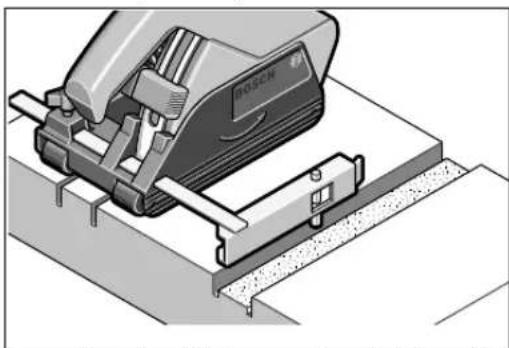
Swivelling Out the Cutting Unit
For a tool change, the cutting unit must be swivelled out completely. Place the machine on a firm surface. Turn the release lock 2 in anticlockwise direction, using e.g. the spanner end of the two-pin spanner 21.
This releases the cutting unit and immediately swivels it upwards by means of resilience.
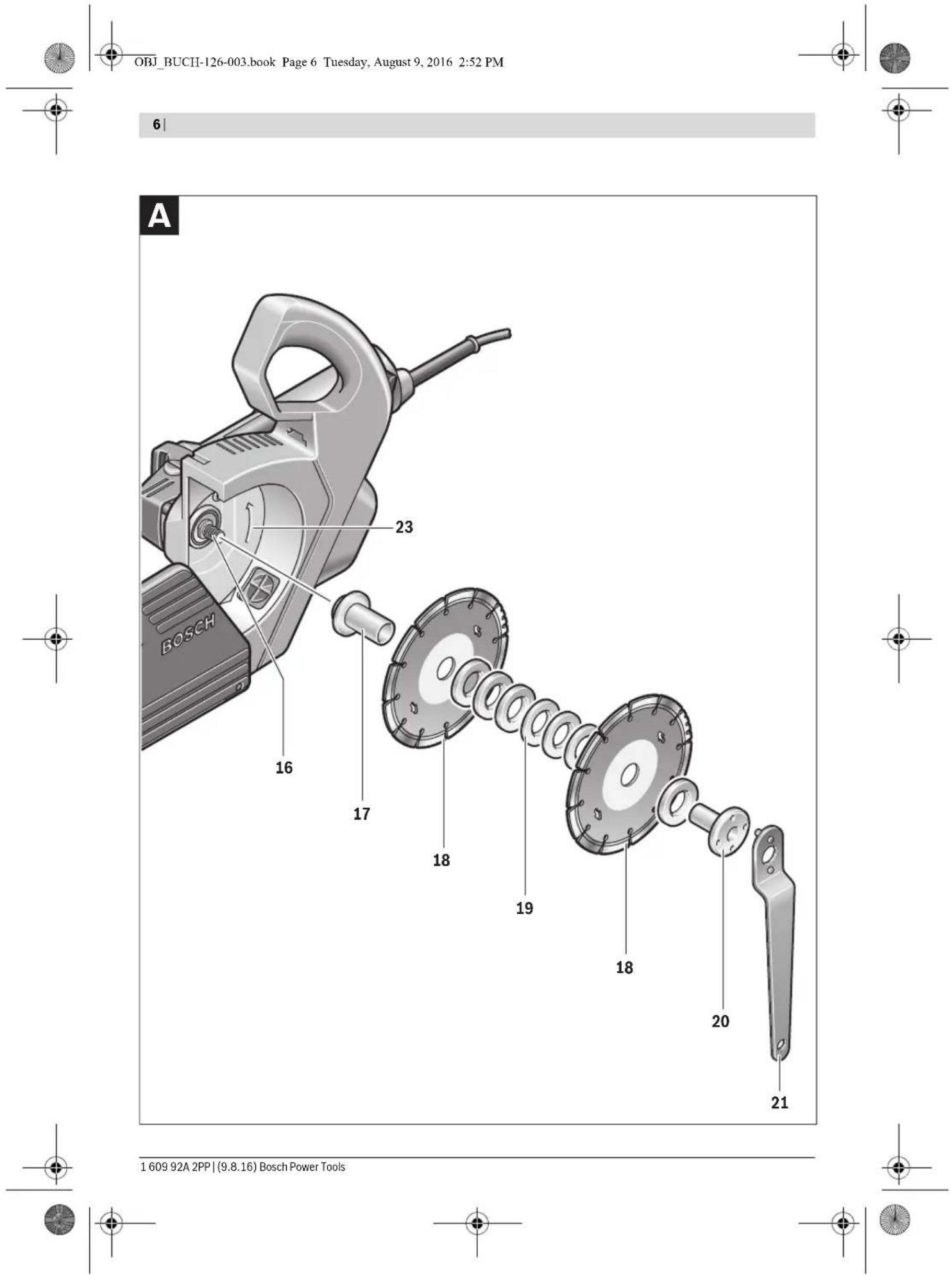
Dismounting the Clamping Assembly (see figure A)
Press the spindle lock button 9 to lock the grinding spindle.
▶ Actuate the spindle lock button only when the grinder spindle is at a standstill. Otherwise, the machine may become damaged.
Loosen the clamping nut 20 with the two-pin spanner 21 and unscrew the clamping nut 20. Remove the spacer discs 19 and the mounting flange 17.
Clean the grinder spindle 16 and all parts to be mounted.
Determining the Slot Width
The slot width results from the amount of spacer discs 19 between the two diamond cutting discs 18 and the cutting width of the diamond cutting discs.
The slot width is calculated as follows:
Slot width = Thickness of the spacer discs + width of the diamond cutting discs.
The allowable slot width is shown in the section "Technical Data".
The machine can be operated with one or two diamond cutting discs.
Mounting the Clamping Assembly (see figure A)
Set the mounting flange 17 onto the grinder spindle 16. The mounting flange with its driving feature must be properly seated on the grinding spindle.
Place the diamond cutting disc 18 and the spacer discs 19 on the mounting flange 17.
▶ Regardless of the requested slot width, all spacer discs 19 provided must always be mounted. Otherwise, the diamond cutting disc 18 can become loose during operation and lead to injuries.
Amount of required spacer discs:
GNF 20 CA: 5 pce., each 4 mm thick
GNF 35 CA: 3 pce., each 4 mm thick and 4 pce., each 6 mm thick.
At least one spacer disc 19 must be mounted between two diamond cutting discs 18.
When mounting the diamond cutting discs, ensure that the direction-of-rotation arrows on the diamond cutting discs match with the rotation rotation direction of the machine (see direction-of-rotation arrow on the gear case).
Press the spindle lock button 9 to lock the grinding spindle.
Screw on the clamping nut 20 and tighten it with the two-pin spanner 21.
Swivel the cutting unit back again. Check the locking system of the cutting unit by pulling the handle.
When working with 2 diamond cutting discs 18, always replace them in pairs.
See graphics page for the mounting sequence.
Operation
Pre-selecting the Cutting Depth
The cutting depth may only be pre-selected when the machine is switched off.
The requested cutting depth can be pre-selected with the depth stop 6.
Press the button for depth stop adjustment 5 and push the depth stop 6 to the requested cutting depth on the cutting-depth scale 4. Release button 5 again.
Ensure that the depth stop 6 is engaged again.
Starting Operation
▶ Observe correct mains voltage! The voltage of the power source must agree with the voltage specified on the nameplate of the machine. Power tools marked with 230 V can also be operated with 220 V.
Switching On and Off
Before starting the machine, check if the cutting unit has engaged in the upper position. Otherwise the diamond cutting discs can touch the workpiece, resulting in possible loss of control over the power tool when switching on.
To start the power tool, push the On/Off switch 10 forwards. To lock the On/Off switch 10, press the On/Off switch 10 down at the front until it latches.
To switch off the power tool, release the On/Off switch 10 or, if it is locked, briefly push down the back of the On/Off switch 10 and then release it.
To save energy, only switch the power tool on when using it.


English | 21
▶ Check the diamond cutting discs before use. The diamond cutting disc(s) must be mounted properly and be able to rotate freely. Carry out a test run for at least one minute without any load. Do not use diamond cutting discs that are damaged, out-of-balance, or vibrate.
Damaged diamond cutting discs can rupture and lead to injuries.
Reduced starting current
The electronic reduced starting current limits the power consumption when switching the tool on and enables operation from a 13 ampere fuse.
Constant Electronic Control
Constant electronic control holds the speed constant at no-load and under load, and ensures uniform working performance.
Overload Protection
When overloaded, the motor comes to a stop. Relieve the load on the machine immediately and allow to cool down for approx. 30 seconds at the highest no-load speed.
Restarting Protection (GNF 35 CA)
The restarting protection feature prevents uncontrolled re-starting of the machine after an interruption in the power supply.
To restart the operation, switch the On/Off switch 10 to the Off position and start the machine again.
Note: Check the function of the restarting protection feature regularly by having the mains plug pulled during operation and plugged in again afterwards.
Working Advice
Exercise caution when cutting slots in structural walls; see Section "Information on Structures".
▶ Do not strain the machine so heavily that it comes to a standstill.
▶ Clamp the workpiece if it does not remain stationary due to its own weight.
The machine may only be used for dry cutting.
Protect the cutting disc against impact, shock and grease. Do not subject the cutting disc to lateral pressure.
- Adjust the cutting depth, see section "Pre-selecting the Cutting Depth". To compensate inaccuracies that occur when breaking away the fin, the cutting depth must be set approx. 3 mm deeper than the requested slot depth.
— Place the machine with the chaser rollers 7 on the surface to be worked. The cutting unit must be in the uppermost position. - Switch on the machine.
- Push the release button 3 upwards to release the cutting unit. Slowly lower and plunge the cutting unit into the material.
– Guide the machine with both handles, applying moderate feed, suited to the material being worked.
— The machine must always work in an up-grinding motion. Otherwise, the danger exists of it being pushed uncon-
trolled out of the cut. Guide the machine in the direction of the working-direction arrow 8.
- The machine can be both pushed or pulled in the cutting direction. Vertical slots can easily be cut by pulling the machine from top to bottom.
- After finishing the working procedure, swivel the cutting unit out of the slot with the machine still running, until the cutting unit engages in the uppermost position.
- Switch the power tool off.
Do not brake coasting diamond cutting discs by applying sideward pressure.
Diamond cutting discs become very hot during operation; do not touch them until they have cooled down.
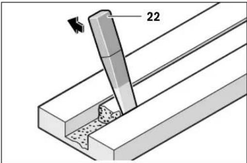
Remove the remaining fin of the material with the break-out tool 22.
Curved cuts are not possible, as the diamond cutting discs could jam in the material.
When cutting through plate materials, ensure that the materials are firmly backed on a surface or supported.
When breaking through walls, e. g. with a rotary hammer, most of the chipping-off of the surface material can be avoided by first cutting in a slot with maximum cutting depth.
For cutting especially hard material, e. g., concrete with high pebble content, the diamond cutting disc can overheat and become damaged as a result. This is clearly indicated by circular sparking, rotating with the diamond cutting disc.
In this case, interrupt the cutting process and allow the diamond cutting disc to cool by running the machine for a short time at maximum speed with no load.
Noticeable decreasing work progress and circular sparking are indications of a diamond cutting disc that has become dull. Briefly cutting into abrasive material (e.g. lime-sand brick) can resharpen the disc again.


22 | English
Parallel Guide (GNF 20 CA)
natural_image
Mechanical assembly diagram showing a Bosch tool pressing a workpiece on a workbench (no text or symbols visible)To cut additional parallel slots, press the guide bolt 15 of the parallel guide 14 down into the already cut slot and then carry out the cutting procedure.
Information on Structures
Slots in structural walls are subject to the Standard DIN 1053 Part 1, or country-specific regulations.
These regulations are to be observed under all circumstances. Before beginning work, consult the responsible structural engineer, architect or the construction supervisor.
The permitted slot depth and width depends on the slot length, wall thickness and the building material used.
Maintenance and Service
Maintenance and Cleaning
▶ Before any work on the machine itself, pull the mains plug.
▶ For safe and proper working, always keep the machine and ventilation slots clean.
After finishing work, dismount the clamping fixtures and clean all clamping parts as well as the protective cover.
Please store and handle the accessory(-ies) carefully.
Service Indicator 11 (GNF 35 CA)
When the carbon brushes are worn out, the machine switches itself off. This is indicated approx. 8 hours beforehand by the lighting or blinking of the service indicator 11. The machine must then be sent to an after-sales service agent. Addresses are listed in the Section "After-sales Service and Application Service".
If the replacement of the supply cord is necessary, this has to be done by Bosch or an authorized Bosch service agent in order to avoid a safety hazard.
Spare Parts
GNF 20 CA
Mounting flange 17 3 600 390 023
Spacer discs, 4 mm 19 3 609 202 041
Clamping nut 20 3 603 345 005
GNF 35 CA
Mounting flange 17 3 609 202 039
Spacer discs, 4 mm 19 3 609 202 041
Spacer discs, 6 mm 19 3 609 202 042
Clamping nut 20 3 609 202 040
After-sales Service and Application Service
Our after-sales service responds to your questions concerning maintenance and repair of your product as well as spare parts. Exploded views and information on spare parts can also be found under:
www.bosch-pt.com
Bosch's application service team will gladly answer questions concerning our products and their accessories.
In all correspondence and spare parts order, please always include the 10-digit article number given on the type plate of the machine.
Great Britain
Robert Bosch Ltd. (B.S.C.)
P.O. Box 98
Broadwater Park
North Orbital Road
Denham
Uxbridge
UB 9 5HJ
At www.bosch-pt.co.uk you can order spare parts or arrange
the collection of a product in need of servicing or repair.
Tel. Service: (0844) 7360109
E-Mail: boschservicecentre@bosch.com
Ireland
Origo Ltd.
Unit 23 Magna Drive
Magna Business Park
City West
Dublin 24
Tel. Service: (01) 4666700
Fax: (01) 4666888
Australia, New Zealand and Pacific Islands
Robert Bosch Australia Pty. Ltd.
Power Tools
Locked Bag 66
Clayton South VIC 3169
Customer Contact Center
Inside Australia:
Phone: (01300) 307044
Fax: (01300) 307045
Inside New Zealand:
Phone: (0800) 543353
Fax: (0800) 428570
Outside AU and NZ:
Phone: +61 3 95415555
www.bosch.com.au
Republic of South Africa
Customer service
Hotline: (011) 6519600
Français | 23
Gauteng - BSC Service Centre
35 Roper Street, New Centre
Johannesburg
Tel.: (011) 4939375
Fax: (011) 4930126
E-Mail: bsctools@icon.co.za
KZN - BSC Service Centre
Unit E, Almar Centre
143 Crompton Street
Pinetown
Tel.: (031) 7012120
Fax: (031) 7012446
E-Mail: bsc.dur@za.bosch.com
Western Cape - BSC Service Centre
Democracy Way, Prosperity Park
Milnerton
Tel.: (021) 5512577
Fax: (021) 5513223
E-Mail: bsc@zsd.co.za
Bosch Headquarters
Midrand, Gauteng
Tel.: (011) 6519600
Fax: (011) 6519880
E-Mail: rbsa-hq.pts@za.bosch.com
Disposal
The machine, accessories and packaging should be sorted for environmental-friendly recycling.
Do not dispose of power tools into household waste!
Only for EC countries:
According to the European Directive 2012/19/EU for Waste Electrical and Electronic Equipment and its implementation into national right, power tools that are no longer usable must be collected separately and disposed of in an environmentally correct manner.
Subject to change without notice.
Français
Executive Vice President Engineering
Helmut Heinzelmann
Head of Product Certification PT/ETM9

Robert Bosch Power Tools GmbH 70538 Stuttgart, GERMANY Stuttgart, 01.01.2017
Montage
natural_image
Mechanical assembly diagram showing a Bosch tool interacting with a rail, no text or symbols presentRobert Bosch (France) S.A.S.
Henk Becker Executive Vice President Engineering Helmut Heinzelmann Head of Product Certification PT/ETM9
jawr Sea i.v. h.w.
Robert Bosch Power Tools GmbH 70538 Stuttgart, GERMANY Stuttgart, 01.01.2017
Montaje
natural_image
Mechanical assembly diagram showing a Bosch tool interacting with a workpiece (no text or symbols visible)Executive Vice President
Head of Product Certification
Engineering
PT/ETM9
if we see i.v. h:m
Robert Bosch Power Tools GmbH
70538 Stuttgart, GERMANY
Stuttgart, 01.01.2017
Montagem
natural_image
Technical illustration of a Bosch tool on a workbench, showing mechanical components and alignment (no text or symbols)Executive Vice President Engineering
Head of Product Certification PT/ETM9

i.v. h=mc
Robert Bosch Power Tools GmbH
70538 Stuttgart, GERMANY
Stuttgart, 01.01.2017
Montaggio
natural_image
Mechanical assembly diagram showing a Bosch tool interacting with a workbench (no text or symbols visible)Executive Vice President
Engineering
Helmut Heinzelmann
Head of Product Certification
PT/ETM9
jaw Bao i.v. h:m
Robert Bosch Power Tools GmbH
70538 Stuttgart, GERMANY
Stuttgart, 01.01.2017
Montage
Stofafzuiging
natural_image
Illustration of a Bosch sewing machine on a cutting board (no text or symbols visible)Executive Vice President Engineering
Helmut Heinzelmann
Head of Product Certification PT/ETM9

Robert Bosch Power Tools GmbH
70538 Stuttgart, GERMANY
Stuttgart, 01.01.2017
Montering
Støvopsugning
natural_image
Mechanical assembly diagram showing a Bosch tool interacting with a workpiece (no text or symbols visible)Bosch Service Center
Telegrafvej 3
2750 Ballerup
På www.bosch-pt.dk kan der online bestilles reservedele eller oprettes en reparations ordre.
Tlf. Service Center: 44898855
Fax: 44898755
E-Mail: vaerktoej@dk.bosch.com
Bortskaffelse
Executive Vice President
Head of Product Certification
Engineering
PT/ETM9

i.v. h=mc
Robert Bosch Power Tools GmbH
70538 Stuttgart, GERMANY
Stuttgart, 01.01.2017
Montage
Dammutsugning
natural_image
Mechanical assembly diagram showing a Bosch tool interacting with a workbench (no text or symbols visible)Bosch Service Center
Telegrafvej 3
2750 Ballerup
Danmark
Tel.: (08) 7501820 (inom Sverige)
Fax: (011) 187691
Avfallshantering
Henk Becker Executive Vice President Engineering Helmut Heinzelmann Head of Product Certification PT/ETM9
JwR Seo i.V. H:m
Robert Bosch Power Tools GmbH 70538 Stuttgart, GERMANY Stuttgart, 01.01.2017
Montering
Støvavsug
natural_image
Mechanical assembly diagram showing a Bosch tool pressing a workpiece on a workbench (no text or symbols visible)Service-melding 11 (GNF 35 CA)
Executive Vice President
Engineering
Helmut Heinzelmann
Head of Product Certification
PT/ETM9

i.v. h=mc
Robert Bosch Power Tools GmbH
70538 Stuttgart, GERMANY
Stuttgart, 01.01.2017
Asennus
Pölynimu
natural_image
Mechanical assembly diagram showing a Bosch tool interacting with a workbench (no text or symbols visible)Executive Vice President
Engineering
Helmut Heinzelmann
Head of Product Certification
PT/ETM9

i.v. h=m
Robert Bosch Power Tools GmbH
70538 Stuttgart, GERMANY
Stuttgart, 01.01.2017
100 | Ελληνικά
Συναρμολόγηση
Αναρρόφηση σκόνης
natural_image
Technical illustration of a Bosch industrial machine on a workbench (no text or symbols visible)Executive Vice President Engineering
Helmut Heinzelmann
Head of Product Certification PT/ETM9

i.v. h=mc
Robert Bosch Power Tools GmbH 70538 Stuttgart, GERMANY Stuttgart, 01.01.2017
Montaj
Toz emme
natural_image
Mechanical assembly diagram showing a cutting machine with a base plate and workpiece (no text or symbols visible)Bosch San. ve Tic. A.S.
Ahi Evran Cad. No:1 Kat:22
Polaris Plaza
80670 Maslak/Istanbul
Bosch Uzman Ekibi +90 (0212) 367 18 88
Işıklar LTD.ŞTİ.
Kızılay Cad. No: 16/C Seyhan
Adana
Tel.: 0322 3599710
Tel.: 0322 3591379
Executive Vice President Engineering
Helmut Heinzelmann
Head of Product Certification PT/ETM9

Robert Bosch Power Tools GmbH 70538 Stuttgart, GERMANY Stuttgart. 01.01.2017
Montaż
System odsysania pytów
natural_image
Mechanical assembly diagram showing a Bosch tool pressing into a workpiece (no text or symbols visible)Robert Bosch Sp. z o.o.
Executive Vice President
Engineering
Helmut Heinzelmann
Head of Product Certification
PT/ETM9

Robert Bosch Power Tools GmbH
70538 Stuttgart, GERMANY
Stuttgart. 01.01.2017
Montáž
Odsávání prachu
natural_image
Mechanical assembly diagram showing a Bosch tool interacting with a workbench (no text or symbols visible)


Slovensky | 127
Bosch Service Center PT
K Vápence 1621/16
692 01 Mikulov
Executive Vice President Engineering
Head of Product Certification PT/ETM9
first Sea i.v. h:m
Robert Bosch Power Tools GmbH
70538 Stuttgart, GERMANY
Stuttgart, 01.01.2017
Montáž
Odsávacie zariadenie
natural_image
Mechanical assembly diagram showing a Bosch tool pressing a workpiece on a base (no text or symbols visible)Executive Vice President
Head of Product Certification
Engineering
PT/ETM9

i.v. h=m
Robert Bosch Power Tools GmbH
70538 Stuttgart, GERMANY
Stuttgart, 01.01.2017
Összeszerelés
Porelszívás
natural_image
Illustration of a Bosch electric shaver machine on a workbench (no text or symbols visible)Executive Vice President
Engineering
Helmut Heinzelmann
Head of Product Certification
PT/ETM9

i.v. h=mc
Robert Bosch Power Tools GmbH
70538 Stuttgart, GERMANY
Stuttgart, 01.01.2017
150 | Русский
Сборка
Пылеотсос
natural_image
Mechanical assembly diagram showing a Bosch tool pressing into a workpiece (no text or symbols visible)Henk Becker Executive Vice President Engineering
Helmut Heinzelmann Head of Product Certification PT/ETM9


Robert Bosch Power Tools GmbH 70538 Stuttgart, GERMANY Stuttgart, 01.01.2017
Монтаж
Відсмоктування пилу
natural_image
Technical illustration of a Bosch sewing machine on a workbench (no text or symbols visible)Executive Vice President Engineering
Helmut Heinzelmann
Head of Product Certification PT/ETM9

i.v. h·w—
Robert Bosch Power Tools GmbH 70538 Stuttgart, GERMANY Stuttgart, 01.01.2017
168|Қазақша
Жинау
Шансорғыш
natural_image
Mechanical assembly diagram showing a Bosch tool interacting with a workpiece (no text or symbols visible)Executive Vice President
Engineering
Helmut Heinzelmann
Head of Product Certification
PT/ETM9

Robert Bosch Power Tools GmbH
70538 Stuttgart, GERMANY
Stuttgart, 01.01.2017
Montare
natural_image
Mechanical assembly diagram showing a Bosch tool pressing a workpiece on a base (no text or symbols visible)Tel. service scule electrice: (021) 4057540
Fax: (021) 4057566
E-Mail: infoBSC@ro.bosch.com
Executive Vice President Engineering
Helmut Heinzelmann
Head of Product Certification PT/ETM9
first Sea i.v. h:m
Robert Bosch Power Tools GmbH 70538 Stuttgart, GERMANY Stuttgart, 01.01.2017
Монтиране
Прахоулавяне
natural_image
Mechanical assembly diagram showing a Bosch tool pressing a workpiece on a workbench (no text or symbols visible)Executive Vice President Engineering
Helmut Heinzelmann
Head of Product Certification PT/ETM9

i.v. h=mc
Robert Bosch Power Tools GmbH
70538 Stuttgart, GERMANY
Stuttgart, 01.01.2017
Монтажа
Вшмукувач за прав
natural_image
Mechanical assembly diagram showing a disassembled machine with mounting base (no text or symbols visible)Executive Vice President Engineering
Helmut Heinzelmann
Head of Product Certification PT/ETM9
jwr Sea i.v. h.w.
Robert Bosch Power Tools GmbH
70538 Stuttgart, GERMANY
Stuttgart. 01.01.2017
Montaža
Usisavanje prašine
▶ Prašine od materijala kao što je premaz koji sadrži olovo, neke vrste drveta, minerali i metal mogu biti štetni po zdravlje. Dodir ili udisanje prašine mogu izazvati alergijske reakcije i/ili oboljenja disajnih puteva radnika ili osoba koje se nalaze u blizini.
Neke prašine kao od hrasta i bukve važe kao izazivači raka, posebno u vezi sa dodatnim materijama za obradu drveta (hromati, zaštitna sredstva za drvo). Materijal koji sadrži azbest smeju raditi samo stručnjaci.
- Koristite što je više moguće usisavanje prašine pogodno za materijal.
- Pobrinite se za dobro provetravanje radnog mesta.
- Preporučuje se, da se nosi zaštitna maska za disanje sa klasom filtera P2.
natural_image
Mechanical assembly diagram showing a Bosch printer on a workbench (no text or symbols visible)Za glodanje daljih kanala, paralelno nekom već postojećem kanalu, pritisnite šinu vodjice 15 paralelnog graničnika 14 na dole u postojeći kanal i na kraju izvodite glodanje.
Uputstva za statiku
Executive Vice President
Engineering
Helmut Heinzelmann
Head of Product Certification
PT/ETM9

i.v. h=m
Robert Bosch Power Tools GmbH
70538 Stuttgart, GERMANY
Stuttgart, 01.01.2017
Montaža
Sesalnik prahu
natural_image
Technical illustration of a Bosch industrial machine with mounting base (no text or symbols)Executive Vice President Engineering
Helmut Heinzelmann
Head of Product Certification PT/ETM9

Robert Bosch Power Tools GmbH 70538 Stuttgart, GERMANY Stuttgart, 01.01.2017
Montaža
Usisavanje prašine
Prašina od materijala kao što su premazi sa sadržajem olova, neke vrste drva, mineralnih materijala i metala, može biti štetna za zdravlje. Dodirivanje ili udisanje prašine može uzrokovati alergijske reakcije i/ili oboljenja dišnih putova korisnika električnog alata ili osoba koje se nalaze u bli-zini.
Određena vrsta prašine, kao što je npr. prašina od hrastovine ili bukve smatra se kancerogenom, posebno u kombinaciji sa dodatnim tvarima za obradu drva (kromat, zaštitna sredstva za drvo). Materijal koji sadrži azbest smiju obradivati samo stručne osobe.
natural_image
Technical illustration of a Bosch industrial machine on a workbench (no text or symbols visible)Executive Vice President Engineering
Helmut Heinzelmann
Head of Product Certification PT/ETM9

i.v. h=mc
Robert Bosch Power Tools GmbH
70538 Stuttgart, GERMANY
Stuttgart, 01.01.2017
Montaž
Tolmueemaldusseadis
natural_image
Mechanical assembly diagram showing a DOSCH tool pressing down on a workbench (no text or symbols visible)Staatikaalased juhised
Executive Vice President Engineering
Helmut Heinzelmann
Head of Product Certification PT/ETM9

Robert Bosch Power Tools GmbH 70538 Stuttgart, GERMANY Stuttgart, 01.01.2017
Montāža
Puteklu uzsükšana
natural_image
Mechanical assembly diagram showing a CNC machine with a base and workpiece (no text or symbols visible)Executive Vice President Engineering
Helmut Heinzelmann
Head of Product Certification PT/ETM9

i.v. h=mc
Robert Bosch Power Tools GmbH
70538 Stuttgart, GERMANY
Stuttgart. 01.01.2017
Montavimas
natural_image
Mechanical assembly diagram showing a Bosch tool pressing a workpiece on a workbench (no text or symbols visible)natural_image
Mechanical assembly diagram showing a Bosch tool pressing into a workpiece (no text or symbols visible)Henk Becker Senior Vice President Engineering
Helmut Heinzelmann Head of Product Certification PT/ETM9
Aur Beo i.v. U: w.c.
Robert Bosch Power Tools GmbH, 70538 Stuttgart, GERMANY Stuttgart, 01.01.2017
التركيب
شف口腔بار
◄ ذي يحتوي على
القص، sep Impact Anouag deschib and delzats and meadon, quad tkoun moudre in thee. En malamse a o uestnshak lafghe qde yuddi eli rdood fvel zandte mssasie w/ao eli amrajd mejare tcnfse de la mstcde m o lde lafhap imtojedin on meqbe mokan. teptir bousla aghe meqine, kaghe biluot andan bya msbne to shrupan, wala siema bataul com mead laadha lalagbe lshb (mog hauo kromyik, maad laadha llghb). I goz an iem meajbe thewad ti tctwoi e lafbostos m n cbl emal mntpocin qfo dun girahm.
natural_image
Mechanical assembly diagram showing a Bosch tool pressing a component on a workbench (no text or symbols visible)| مCADIR MACHSHE SHDE BR TBP(5) EN 60745 | |||
| 102 | 94 | dB(A) | SAPC PSOTI KLAS A ARZIBI SHDE DRCHUOS IYN NOG ABAR BRCI MEADL ASST BA |
| 113 | 105 | dB(A) | SAPC FSHAR PSOTI |
| 3 | 3 | dB | SAPC TOAN PSOTI K (SAPC CHTA) K (SAPC CHTA) K (SAPC CHTA) K (SAPC CHTA) K (SAPC CHTA) K (SAPC CHTA) K (SAPC CHTA) K (SAPC CHTA) K (SAPC CHTA) K (SAPC CHTA) K (SAPC CHTA) K (SAPC CHTA) |
| AZ GOWSI IMNI IMNI ASFTADHE KND! | |||
| MIZAN KIL ARTEASHAT (JEGB PDRARHAT SAE JHET) and RIBP CHTA K (SAPC CHTA) K (SAPC CHTA) K (SAPC CHTA) K (SAPC CHTA) K (SAPC CHTA) K (SAPC CHTA) K (SAPC CHTA) K (SAPC CHTA) K (SAPC CHTA) K (SAPC CHTA) K (SAPC CHTA)K (SAPC CHTA) K (SAPC CHTA) K (SAPC CHTA) K (SAPC CHTA) K (SAPC CHTA) K (SAPC CHTA) K (SAPC CHTA) K (SAPC CHTA) K (SAPC CHTA) K (SAPC CHTA) K (SAPC CHTA) K(EN 60745) | |||
| = 4,0 | = 4,0 | m/s2 | a h |
| = 1,5 | = 1,5 | m/s2 | K |
OBJ_BUCH-126-003.book Page 260 Tuesday, August 9, 2016 2:52 PM

260
UPP

professional plus

BPP

professional plus

HPP

professional plus


APP

professional plus


UP

professional

UP-T

professional


| 261