GNB 18V-12 Professional - Stapler BOSCH - Free user manual and instructions
Find the device manual for free GNB 18V-12 Professional BOSCH in PDF.

| Product Type | Cordless Concrete and Steel Stapler |
| Brand | Bosch |
| Model | GNB 18V-12 Professional |
| Rated Voltage | 18 V |
| Motor Type | Brushless DC Motor |
| Cycle Rate | 2 shots per second |
| Nail Length Range | 13 mm – 38 mm (0.5 to 1.5 in) |
| Nail Shank Diameter | 2.7 mm – 3 mm (0.11–0.12 in) |
| Nail Head Diameter (collated) | 6.25 mm (0.25 in) |
| Nail Head Diameter (single shot) | 8 mm (0.3 in) |
| Standard Magazine Capacity | 22 nails |
| Operating Ambient Temperature | -5 °C to +50 °C |
| Storage Temperature | -20 °C to +50 °C |
| Weight (without battery pack) | Approximately 2.8 kg (estimated) |
| Power Supply | 18 V lithium-ion battery pack (Core18V series) |
| Main Functions | Fastening in concrete, mild steel, cold-rolled steel; electrical cable attachment |
| Safety | Trigger lock, dry-fire lock, overheat, low temperature, and overcurrent protection |
| Maintenance and Cleaning | Clean vents and magazine; use a damp cloth with mild soap |
| Spare Parts and Repairability | Front nosepieces, magazines, suspension hook; repair by Bosch authorized service center |
| General Information | Limited warranty: 5 years for tool, 3 years for batteries (18 V) |
Frequently Asked Questions - GNB 18V-12 Professional BOSCH
User questions about GNB 18V-12 Professional BOSCH
0 question about this device. Answer the ones you know or ask your own.
Ask a new question about this device
Download the instructions for your Stapler in PDF format for free! Find your manual GNB 18V-12 Professional - BOSCH and take your electronic device back in hand. On this page are published all the documents necessary for the use of your device. GNB 18V-12 Professional by BOSCH.
USER MANUAL GNB 18V-12 Professional BOSCH
IMPORTANT Read Before Using
IMPORTANT Lire avant usage
IMPORTANTE Leer antes de usar

natural_image
Icon of a person reading a book inside a circle (no text or symbols)Operating / Safety Instructions Consignes d'utilisation / de sécurité Instrucciones de funcionamiento y seguridad
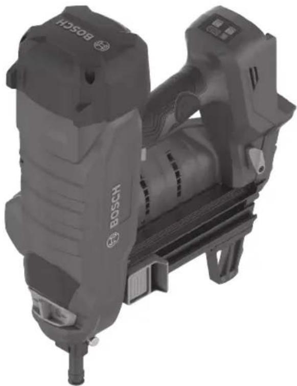
GNB18V-12 Concrete Nailer
natural_image
Exterior view of a Bosch electric drill press device (no text or symbols visible on the device body)
BOSCH
Call Toll Free for Consumer Information & Service Locations Pour obtenir des informations et les adresses de nos centres de service après-vente, appelez ce numéro gratuit Llame gratis para obtener información para el consumidor y ubicaciones de servicio
1-877-BOSCH99 (1-877-267-2499) www.boschtools.com
For English Version See page 2
| The definitions below describe the level of severity for each signal word.Please read the manual and pay attention to these symbols. | |
 | This is the safety alert symbol. It is used to alert you to potential personal injury hazards. Obey all safety messages that follow this symbol to avoid possible injury or death. |
 | DANGER indicates a hazardous situation which, if not avoided, will result in death or serious injury. |
 | WARNING indicates a hazardous situation which, if not avoided, could result in death or serious injury. |
 | CAUTION indicates a hazardous situation which, if not avoided, could result in minor or moderate injury. |
Table of Contents
Safety Symbols....2
General Power Tool Safety Warnings.....3
Safety Warnings for Cordless
Nailer Tools....5
Additional Safety Warnings .... 5
Disposal....7
Intended Use....7
Specifications....8
Fastener Selection....9
Symbols....10
Getting to Know Your GNB18V-12
Concrete Nailer....11
Unpacking and Checking Contents ..... 13
Unpacking the Nailer .... 13
Assembly....14
Removing and Installing the
Magazine and Nosepiece....14
Removing and Attaching the
Supporting Leg 15
Inserting and Removing
the Battery Pack 16
Utility Hook 16
Operation 17
Daily Inspection and Testing ..... 17
Work Surface Suitability and
Center Punch Test 17
Loading Collated Magazine ..... 18
Dry Fire Lock Out....18
Loading Single Shot Fasteners.....19
User Interface 20
Trigger Lock 21
Built-in Work Light....21
Depth of Drive Adjustment ..... 21
Nailer Actuation....22
Maintenance 23
General Maintenance....23
Service....23
Cleaning 23
Repairs 23
Accessories....24
Troubleshooting 24
Jam Clearing 24
2 SAVE THESE INSTRUCTIONS
General Power Tool Safety Warnings
WARNING
Read all safety warnings, instructions, illustrations and specifications provided with this power tool. Failure to follow all instructions listed below may result
in electric shock, fire, and/or serious injury.
SAVE ALL WARNINGS AND INSTRUCTIONS FOR FUTURE REFERENCE
The term “power tool” in the warnings refers to your mains-operated (corded) power tool or battery-operated (cordless) power tool.
1. Work area safety
a. Keep work area clean and well lit. Cluttered or dark areas invite accidents.
b. Do not operate power tools in explosive atmospheres, such as in the presence of flammable liquids, gases or dust. Power tools create sparks which may ignite the dust or fumes.
c. Keep children and bystanders away while operating a power tool. Distractions can cause you to lose control.
2. Electrical safety
a. Power tool plugs must match the outlet. Never modify the plug in any way. Do not use any adapter plugs with earthed (grounded) power tools. Unmodified plugs and matching outlets will reduce risk of electric shock.
b. Avoid body contact with earthed or grounded surfaces, such as pipes, radiators, ranges and refrigerators. There is an increased risk of electric shock if your body is earthed or grounded.
c. Do not expose power tools to rain or wet conditions. Water entering a power tool will increase the risk of electric shock.
d. Do not abuse the cord. Never use the cord for carrying, pulling or unplugging the power tool. Keep cord away from heat, oil, sharp edges or moving parts. Damaged or entangled cords increase the risk of electric shock.
e. When operating a power tool outdoors, use an extension cord suitable for outdoor use. Use of a cord suitable for outdoor use reduces the risk of electric shock.
f. If operating a power tool in a damp location is unavoidable, use a Ground Fault Circuit Interrupter (GFCI) protected supply. Use of an GFCI reduces the risk of electric shock.
3. Personal safety
a. Stay alert, watch what you are doing and use common sense when operating a power tool. Do not use a power tool while you are tired or under the influence of drugs, alcohol or medication. A moment of inattention while operating power tools may result in serious personal injury.
b. Use personal protective equipment. Always wear eye protection. Protective equipment such as a dust mask, non-skid safety shoes, hard hat, or hearing protection used for appropriate conditions will reduce personal injuries.
c. Prevent unintentional starting. Ensure the switch is in the off-position before connecting to power source and / or battery pack, picking up or carrying the tool. Carrying power tools with your finger on the switch or energizing power tools that have the switch on invites accidents.
d. Remove any adjusting key or wrench before turning the power tool on. A wrench or a key left attached to a rotating part of the power tool may result in personal injury.
e. Do not overreach. Keep proper footing and balance at all times. This enables better control of the power tool in unexpected situations.
f. Dress properly. Do not wear loose clothing or jewelry. Keep your hair and clothing away from moving parts. Loose clothes, jewelry or long hair can be caught in moving parts.
g. If devices are provided for the connection of dust extraction and collection facilities, ensure these are connected and properly used. Use of dust collection can reduce dust-related hazards.
h. Do not let familiarity gained from frequent use of tools allow you to become complacent and ignore tool safety principles. A careless action can cause severe injury within a fraction of a second.
SAVE THESE INSTRUCTIONS 3
General Power Tool Safety Warnings
4. Power tool use and care
a. Do not force the power tool. Use the correct power tool for your application. The correct power tool will do the job better and safer at the rate for which it was designed.
b. Do not use the power tool if the switch does not turn it on and off. Any power tool that cannot be controlled with the switch is dangerous and must be repaired.
c. Disconnect the plug from the power source and/or remove the battery pack, if detachable, from the power tool before making any adjustments, changing accessories, or storing power tools. Such preventive safety measures reduce the risk of starting the power tool accidentally.
d. Store idle power tools out of the reach of children and do not allow persons unfamiliar with the power tool or these instructions to operate the power tool. Power tools are dangerous in the hands of untrained users.
e. Maintain power tools and accessories. Check for misalignment or binding of moving parts, breakage of parts and any other condition that may affect the power tool's operation. If damaged, have the power tool repaired before use. Many accidents are caused by poorly maintained power tools.
f. Keep cutting tools sharp and clean. Properly maintained cutting tools with sharp cutting edges are less likely to bind and are easier to control.
g. Use the power tool, accessories and tool bits etc. in accordance with these instructions, taking into account the working conditions and the work to be performed. Use of the power tool for operations different from those intended could result in a hazardous situation.
h. Keep handles and grasping surfaces dry, clean and free from oil and grease. Slippery handles and grasping surfaces do not allow for safe handling and control of the tool in unexpected situations.
5. Battery tool use and care
a. Recharge only with the charger specified by the manufacturer. A charger that is suitable for one type of battery pack may create a risk of fire when used with another battery pack.
b. Use power tools only with specifically designated battery packs. Use of any other battery packs may create a risk of injury and fire.
c. When battery pack is not in use, keep it away from other metal objects like paper clips, coins, keys, nails, screws, or other small metal objects that can make a connection from one terminal to another. Shorting the battery terminals together may cause burns or a fire.
d. Under abusive conditions, liquid may be ejected from the battery; avoid contact. If contact accidentally occurs, flush with water. If liquid contacts eyes, additionally seek medical help. Liquid ejected from the battery may cause irritation or burns.
e. Do not use a battery pack or tool that is damaged or modified. Damaged or modified batteries may exhibit unpredictable behaviour resulting in fire, explosion or risk of injury.
f. Do not expose a battery pack or tool to fire or excessive temperature. Exposure to fire or temperature above 265 °F may cause explosion.
g. Follow all charging instructions and do not charge the battery pack or tool outside the temperature range specified in the instructions. Charging improperly or at temperatures outside the specified range may damage the battery and increase the risk of fire.
6. Service
a. Have your power tool serviced by a qualified repair person using only identical replacement parts. This will ensure that the safety of the power tool is maintained.
b. Never service damaged battery packs. Service of battery packs should only be performed by the manufacturer or authorized service providers.
4 SAVE THESE INSTRUCTIONS
Safety Warnings for Cordless Nailer Tools
a. Always assume that the tool contains fasteners. Careless handling of the tool can result in unexpected firing of fasteners and personal injury.
b. Do not point the tool towards yourself or anyone nearby. Unexpected triggering will discharge the fastener causing an injury.
c. Do not actuate the tool unless the tool is placed firmly against the workpiece. If the tool is not in contact with the workpiece, the fastener may be deflected away from your workpiece.
d. Disconnect the tool from the power source when the fastener jams in the tool. While removing a jammed fastener, the nailer may be accidentally activated if it is plugged in.
e. Use caution while removing a jammed fastener. The mechanism may be under compression and the fastener may be forcefully discharged while attempting to free a jammed condition.
f. When fastening electrical cables, make sure the cables are not energized. Hold the tacker only by insulated gripping surfaces. Use only fasteners designed for electrical cable installations. Inspect that the fastener has not damaged the insulation of the electrical cables. A fastener that damages the insulation of electric cables can lead to electric shock and fire hazards.
Additional Safety Warnings
Do not fire fasteners into walls or floors without assuring the area on the opposite side is clear. A fastener could travel through the work surface, causing property damage or injury.
Do not drive fasteners into walls, floors, or other work areas without knowing what may be damaged by the driven fastener. Fasteners driven into live electrical wires, plumbing, gas piping, or other types of obstructions can result in electrocution, explosion, personal injury and/or property damage.
Hold the power tool by identified insulated gripping surfaces when performing an operation where the fastener may contact hidden wiring. Fasteners contacting a "live" wire may make exposed metal parts of the power tool "live" and result in electric shock or electrocution.
Do not tamper with, remove, or cause nailer operating controls to become inoperable. Missing or improperly operating nailer controls can cause unexpected actuation and personal injury.
Never keep a finger on the trigger when not driving fasteners or carrying the tool. Carry the tool only by the handle. Keeping a finger on the trigger when carrying the tool, or when not driving fasteners can result in unintentional triggering and personal injury.
When loading fasteners ensure that the fastener heads align with the nosepiece of the tool. If fasteners are not aligned with the nosepiece, tool may jam or misfire causing property damage or injury.
Use only the fasteners meeting the criteria listed in the “Specification” section of this manual. Fasteners not identified for use with this tool can cause the tool to malfunction and result in the risk of injury and/or tool damage.
Keep hands and feet at least 8 inches (200mm) away from the nosepiece of the tool during use. Fasteners may deflect and cause property damage or personal injury.
Do not drive a fastener on top of another fastener. This could cause the fastener to be deflected or the tool to react in an unexpected manner causing injury.
Do not engage in horseplay. The discharged fasteners are projectiles capable of causing serious injury.
Never actuate the nailer unless it is perpendicular to the workpiece surface and the workpiece surface is free of debris. The fastener may be deflected if the nailer is not in proper contact with the workpiece resulting in property damage or personal injury.
SAVE THESE INSTRUCTIONS 5
Additional Safety Warnings
Do not drive fasteners into unsuitable materials. Materials that are too hard can cause the fastener to deflect. Brittle materials can crumble and allow the fastener to break through. Materials that are too soft can allow the fastener to break through. These conditions can result in property damage or serious personal injury.
Do not pull the trigger or depress the nosepiece when loading the nailer. Pulling the trigger or depressing the nosepiece may cause misfiring of the tool resulting in personal injury and property damage.
Load only one single shot fastener at a time. Loading multiple fasteners can cause misfiring and damage the nailer.
Do not use the utility hook or its mounting location for tether attachments. The utility hook and its mounting location are not intended to support tethering loads.
Do not use the utility hook if it appears damaged or deformed. A damaged or deformed utility hook may result in unstable hanging and the tool unexpectedly falling, causing property damages and personal injury.
Never wedge the nosepiece between two or more surfaces. Gap between the nosepiece and multiple work surfaces may allow deflection of the fastener and property damage or personal injury.
Never hold back the nosepiece during operation. Holding the nosepiece back can result in unexpected actuation and may cause property damage or serious injury.
Never position your face or body over the nailer top cap during operation. The nailer will recoil when driving a fastener.
⚠ WARNING Do not operate the nailer if it does not pass daily inspection and testing. Operating a nailer that does not pass the daily inspection and testing may result in property damage and personal injury.
⚠ WARNING To reduce the risk of injury, always wear safety goggles or glasses with side shields. The operator and other people in the work area must wear eye protection in accordance with ANSI Z87.1. Eye protection does not fit all operators in the same way. Make sure the eye protection chosen has side shields or provides protection from flying debris both from the front and sides. The em-
ployer is responsible for enforcing the use of eye protection by the operator and other people in the work area. When required, wear head protection in accordance with ANSI Z89.1.
⚠ WARNING Some dust created by power sanding, sawing, grinding, drilling, and other construction activities contains chemicals known to cause cancer, birth defects or other reproductive harm. Some examples of these chemicals are:
- Lead from lead-based paints,
• Crystalline silica from bricks and cement and other masonry products, and - Arsenic and chromium from chemically-treated lumber.
Your risk from these exposures varies, depending on how often you do this type of work. To reduce your exposure to these chemicals: work in a well ventilated area, and work with approved safety equipment, such as those dust masks that are specially designed to filter out microscopic particles.
6 SAVE THESE INSTRUCTIONS
Additional Safety Warnings
Disposal
This section is part of Robert Bosch Tool Corporation's commitment to preserving our environment and conserving our natural resources.
TOOL DISPOSAL
Do not dispose of power tools and batteries/re-chargeable batteries into household waste!
BATTERY DISPOSAL
WARNING
Do not attempt to disassemble the battery or remove any components projecting from the battery terminals. Fire or injury may result. Prior to disposal, protect exposed terminals with heavy insulating tape to prevent shorting.
LITHIUM-ION BATTERIES
If equipped with a lithium-ion battery, the battery must be collected, recycled, or disposed of in an environmentally sound manner.
"The EPA certified RBRC Battery Recycling Seal on the lithium-ion (Li-ion) battery indicates Robert Bosch Tool Corporation is voluntarily participating in an industry

program to collect and recycle these batteries at the end of their useful life, when taken out of service in the United States or Canada. The RBRC program provides a convenient alternative to placing used Li-ion batteries into the trash or the municipal waste stream, which may be illegal in your area.
Please call 1-800-8-BATTERY for information on Li-ion battery recycling and disposal bans/restrictions in your area or return your batteries to a Bosch/Dremel Service Center for recycling. Robert Bosch Tool Corporation's involvement in this program is part of our commitment to preserving our environment and conserving our natural resources"
Intended Use
This is a hand-held, cordless, sequentially operated fastening tool. It is designed to drive specially manufactured fasteners into poured, precast, and pre-stressed concrete, and grout-filled concrete block. It is also designed to drive specially manufactured fasteners into mild and cold-rolled steel of at least 22 ga. thickness.
The fastening tool is also designed to fasten electrical cables with clips if the appropriate fasteners are used. Use only approved fasteners in combination with their corresponding fastener guide (see the sections headed "Specifications" and "Fastener Selection").
DO NOT USE NAILER FOR FASTENING INTO THESE MATERIALS
• Wood and wood products
• Vertical mortar or grouted joints
- Bricks
• Hollow block or tile
- Glazed tile
- Glass
• Hardened or tool grade steel
- Cast iron
• Welded areas or torch cuts
- Spring steel
- Natural stone
SAVE THESE INSTRUCTIONS 7
Specifications
| Model Number GNB18V-12 | |
| Voltage rating 18 V | === |
| Motor type DC Brushless | |
| Cycle rate 2 Shots/Second* | |
| Collation angle 0° | |
| Nail length range 0.5 to 1.5 inch (13 mm – 38 mm) | |
| Nail shank diameter 0.11-0.12 inch (2.7mm – 3mm) | |
| Nail Head diameter (Collated Fasteners) 0.25 inch (6.25mm) | |
| Nail Head diameter (Single Shot Fasteners) 0.3 inch (8mm) | |
| Standard Collated Nail Magazine capacity 22 Nails | |
| Operating ambient temperature** +23...+122°F (-5...+50°C) | |
| Storage Temperature -4...+122°F (-20...+50°C) |
* Using Core18V battery packs 4.0 Ah, 8.0 Ah, 12 Ah
** The nailer will not operate below 23°F (-5°C) or above 50°F (122°C).
Battery Packs / Chargers:
Please refer to the battery/charger list, included with your tool.
Fastener Selection
For best performance, use the following Bosch fasteners for the intended application.
| Designation | Length, inch (mm) | Shank Diameter inch (mm) | Head Diameter inch (mm) | Material Collation Suitable for | ||
| NB-063 5/8 | (16) | 0.11 (2.7) Smooth | 0.25 (6.25) | Galvanized Carbon Steel | Polyamide, Blue | Concrete |
| NB-075 3/4 | (19) | |||||
| NB-100 1 | (25) | |||||
| NB-125 1-1/4 | (32) | |||||
| NB-150 1-1/2 | (38) | |||||
| NM-050 1/2 | (13) | 0.12 (3) Stepped | Polyamide, Black | SteelNM-063 5/8 (16) | ||
| NM-075 3/4 | (19) | |||||
| NK-138 1-3/8 | (35) | 0.11 (2.7) Knurled | Polyamide, Blue | Concrete | ||
Certificate for all the fasteners available in ICC-ES ESR-4893 evaluation report.
Single Shot Fasteners: Compatible single shot fasteners are 0.300" (8mm) nominal diameter. The fastener should slide easily into the Single Shot Nosepiece and not fall out.

Scan QR Code to view full selection of Bosch fasteners

Symbols
Important: Some of the following symbols may be used on your tool. Please study them and learn their meaning. Proper interpretation of these symbols will allow you to operate the tool better and safer.
| Symbol Designation/Explanation | |
| V Volts (voltage) | |
| A Amperes (current) | |
| Hz Hertz (frequency, cycles per second) | |
| W Watt (power) | |
| kg Kilograms (weight) | |
| min Minutes (time) | |
| s Seconds (time) | |
| 0 Off position (zero speed, zero torque...) | |
| → | Arrow (action in the direction of arrow) |
| === | Type or a characteristic of current |
 | Alerts user to read manual. |
 | Alerts user to wear eye protection. |
 | This symbol designates that this tool is listed by the Canadian Standards Association, to United States and Canadian Standards. |
 | Designates Li-ion battery recycling program. |
Getting to Know Your GNB18V-12 Concrete Nailer
Fig. 1
Getting to Know Your GNB18V-12 Concrete Nailer
Fig. 2
natural_image
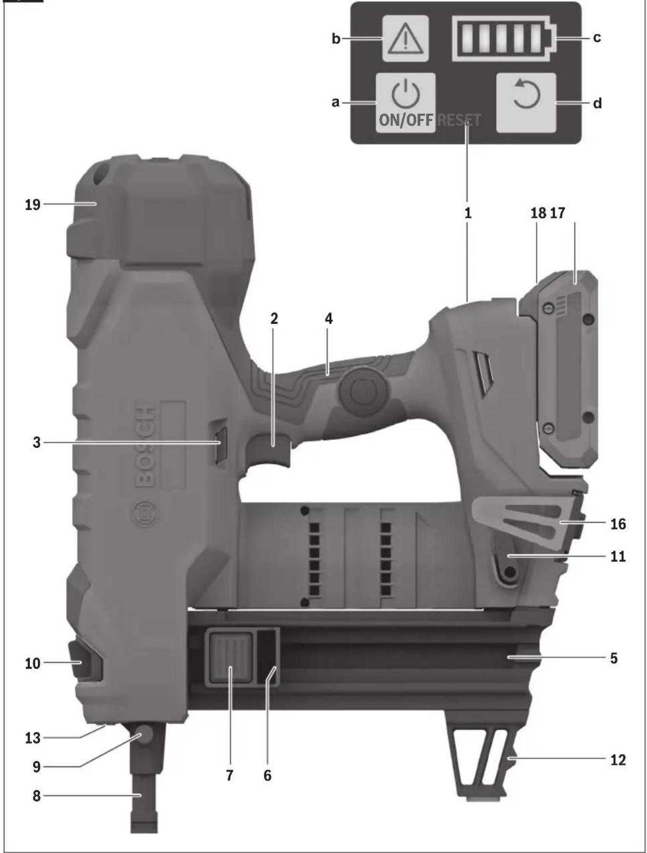
Technical illustration of a mechanical bracket assembly with labeled parts (12 and 14), no text or symbols present.1 User Interface
a ON/OFF Button
b Status Indicator
c Battery Charge Indicator
d Reset Button
2 Trigger
3 Trigger Lock
4 Handle (Insulated Gripping Surface)
5 Collated Magazine
6 Magazine Slider
7 Magazine Slider Button
8 Collated Nosepiece
9 Nosepiece Release Button
10 Depth Setting Switch
11 Magazine Release Lever
12 Supporting Leg
13 Worklight
14 Single Shot Magazine
15 Single Shot Nosepiece (marked with white stripe)
16 Utility Hook
17 Battery Pack
18 Battery Pack Release Button
19 Top Cap
Unpacking and Checking Contents
Unpacking the Nailer
Your nailer is shipped complete in one carton.
Separate all parts from the packing materials, and check each one with the illustration and the list of loose parts to make certain all items are accounted for before discarding any packing material.
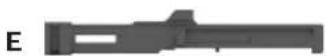
| Loose Parts (Fig. 3) | ||
| Item | Description Qty. | |
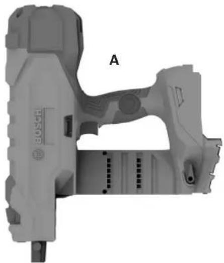
| A | Nailer 1 | |
| B | Collated Magazine and Supporting Leg | 1 |
| C | Single Shot Magazine and Supporting Leg | 1 |
| D | Collated Nosepiece 1 | |
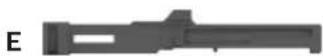
| E | Single Shot Nosepiece 1 | |
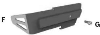
| F | Utility Hook 1 | |
| G | Utility Hook Screw 1 | |
Fig. 3
natural_image
3D rendered mechanical component with labeled section A, no readable text or symbols beyond part label
natural_image
3D model of a mechanical component with labeled part B, showing internal structure and mounting bracket (no text or symbols beyond label)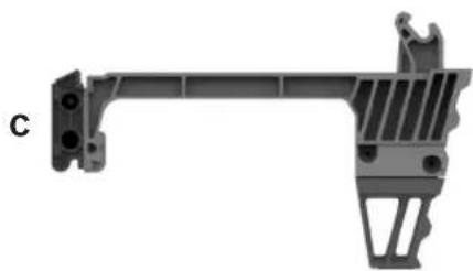
natural_image
Mechanical bracket component with mounting holes and internal structure (no text or symbols visible)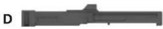
natural_image
3D model of a mechanical part with cutouts and a small connector (no text or symbols visible)Assembly
WARNING
Disconnect battery pack from tool before assembly, adjustments, troubleshooting or changing accessories. Such preventive safety measures reduce the
risk of starting the tool accidentally, which may result in personal injury.
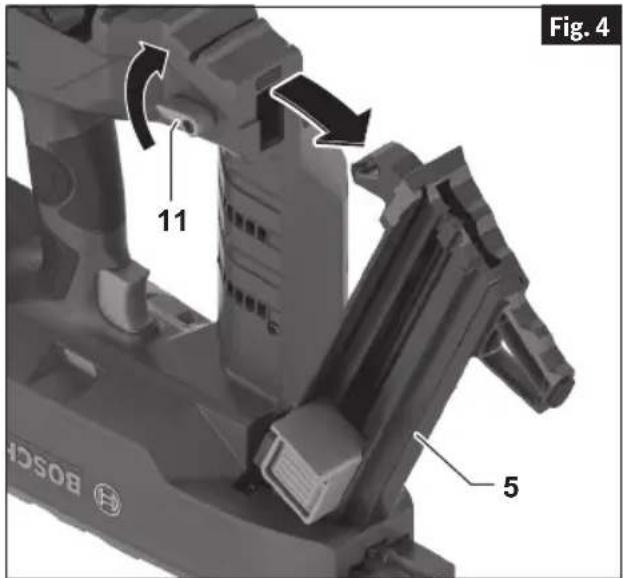
Removing and Installing the Magazine and Nosepiece
(Fig. 1, 2, 4, 5, 6, 7, 8)
Install the Nosepiece first then assemble the Collated or Single Shot Magazine. If the magazine is assembled first, then it will not be possible to fully insert the Nosepiece.
When working with collated fasteners, install the Collated Nosepiece 8 and the Collated Magazine 5.
When working with single shot fasteners, install the the Single Shot Nosepiece 15 and the Single Shot Magazine 14.
- Remove the battery pack.
- Position nailer onto a flat stable surface.
- Remove the Magazine:
a. Rotate the Magazine Release Lever 11 clockwise and pull out the end of the Magazine 5, 14 to remove from the nailer (Fig. 4).
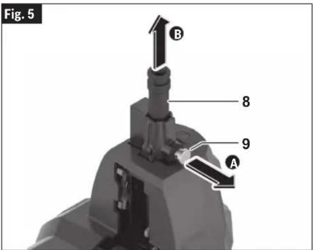
- Remove the Nosepiece:
a. Pull the Nosepiece Release Button 9 and remove the Nosepiece 8, 15 from the nailer (Fig. 5).
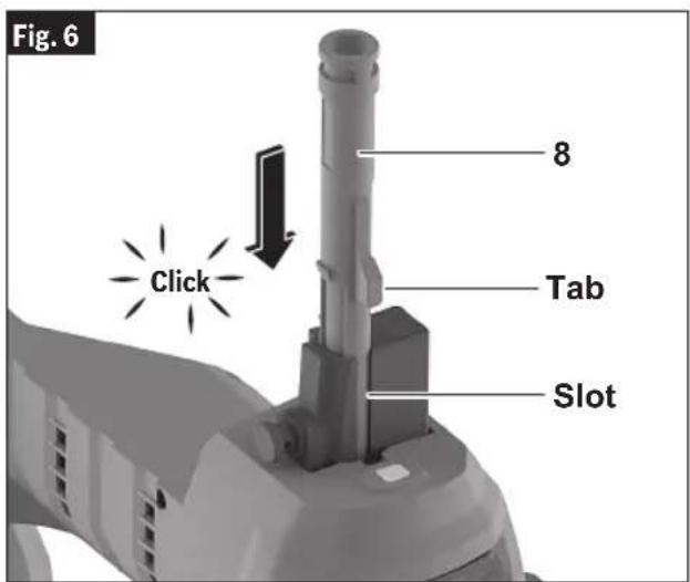
- Insert the Nosepiece:
a. Align the tab of the Nosepiece 8, 15 to the slot in the housing and push the Nosepiece into the nailer until the Nosepiece Release Button locks it in place. The Nosepiece is properly installed when you hear a "click" (Fig. 6).
Assembly

natural_image
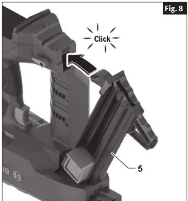
Mechanical assembly diagram showing a robotic arm and a mechanical component with a numbered arrow indicating a specific part (no text or symbols present)- Install the Magazine:
a. Insert the Magazine 5, 14, as seen in (Fig 7).
b. Lock the Magazine 5, 14 by pushing the magazine flush against the nailer (Fig 8). The Magazine is properly installed when you hear a "click".
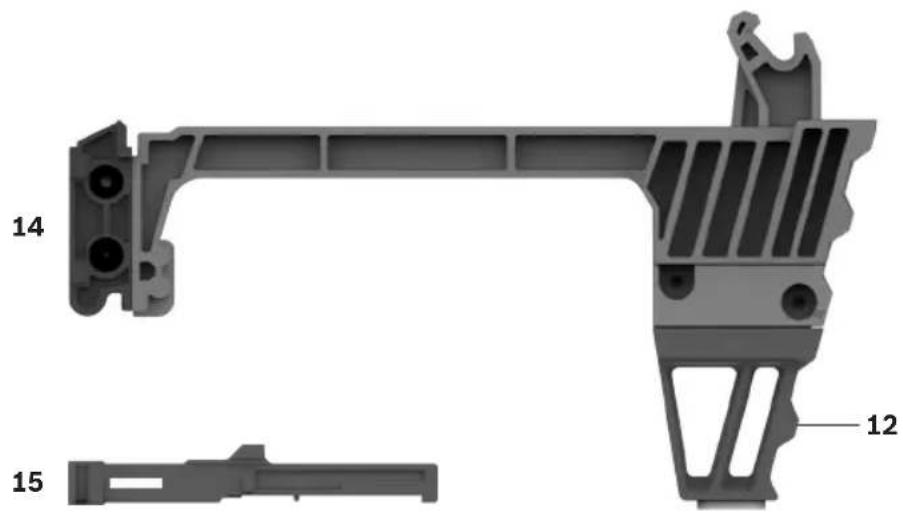
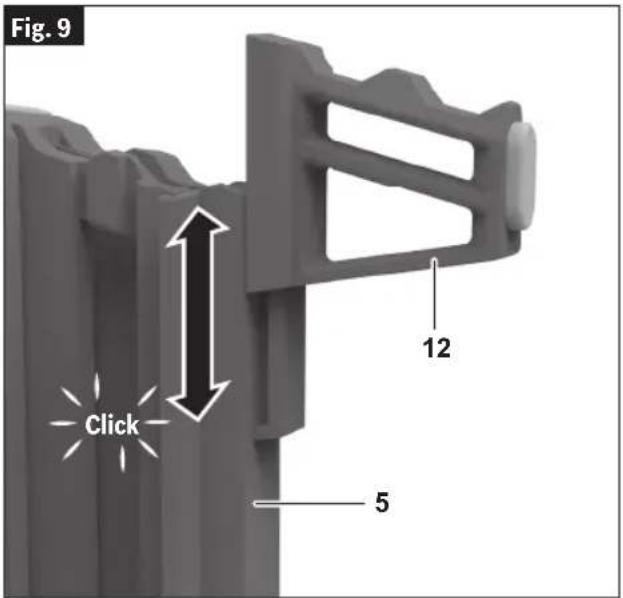
Removing and Attaching the Supporting Leg
(Fig. 2, 9)
The Supporting Leg helps the Nosepiece to be perpendicular to a flat surface.
The Supporting Leg can be removed for work on an uneven surface.
To remove, slide the Supporting Leg 12 off the end of the Magazine 5, 14. To reattach, slide the Supporting Leg 12 back on the end of Magazine until it clicks in place (Fig. 9).
Assembly
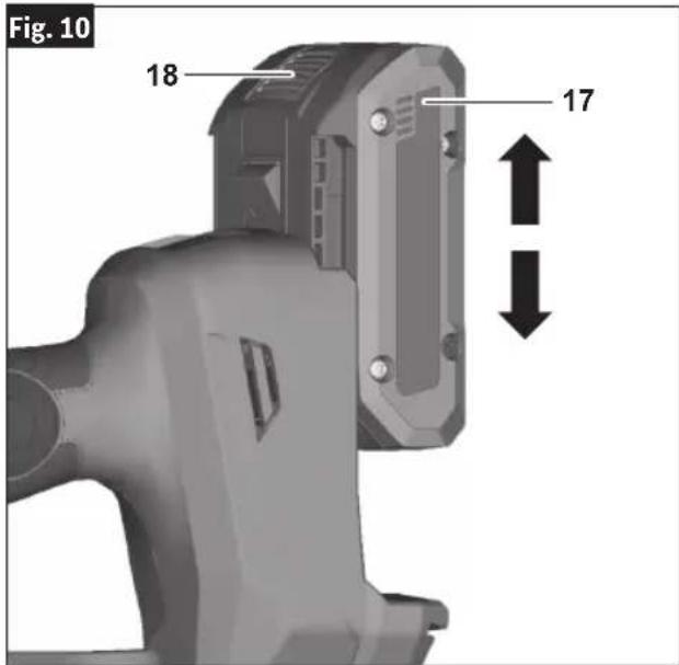
Inserting and Removing the Battery Pack
To Insert the Battery Pack
(Fig. 1, 10)
- Set Trigger Lock 3 to the locked position.
- Slide charged Battery Pack 17 into the housing until the battery pack locks into position.
Your tool is equipped with a secondary locking latch to prevent the battery pack from completely falling out of the handle, should it become loose due to vibration.
To Remove the Battery Pack
(Fig. 10)
- Press the Battery Pack Release Button 18 and slide the Battery Pack 17 from the housing.
- Press the Battery Pack Release Button 18 again and slide the Battery Pack 17 completely out of tool housing.
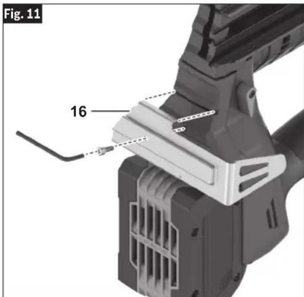
Utility Hook
(Fig. 11)
WARNING
Do not use the utility hook or its mounting location for
tether attachments. The utility hook and its mounting location are not intended to support tethering loads.
WARNING
Do not use the utility hook if it appears damaged or de-
formed. A damaged or deformed utility hook may result in unstable hanging and the tool unexpectedly falling, causing property damages and personal injury.
Install the Utility Hook 16 using the screw included with this nailer into the bottom of the nailer (Fig. 11).
Operation
WARNING
Always observe the following safety precautions in addition to the safety instructions on pages 2 through 7. Failure to do so may result in equipment dam-
age, property damage, or personal injury.
WARNING
Disconnect battery pack from tool before assembly, adjustments, troubleshooting or changing accessories. Such preventive safety measures reduce the
risk of starting the tool accidentally, which may result in personal injury.
WARNING
Use personal protective equipment. Always wear eye
protection. Protective equipment such as a dust mask, non-skid safety shoes, hard hat, or hearing protection used for appropriate conditions will reduce personal injuries.
This nailer operates only in a fully sequential actuation mode. To fire a fastener, first the Nosepiece must be fully depressed against the workpiece, then the Trigger must be pressed. To fire another fastener the Trigger and Nosepiece must be released and the firing sequence repeated.
Note: The Trigger has to be pressed within 2 seconds after the Nosepiece is fully pressed. If the Trigger is pressed later, the nailer will revert to a SAFE mode and the actuation sequence will have to be repeated.
For optimal performance and reliable service life, operate the nailer within the specified ambient temperature range.
Daily Inspection and Testing
WARNING
Do not operate the nailer if it does not pass daily inspec-
tion and testing. Operating a nailer that does not pass the daily inspection and testing may result in property damage and personal injury.
Perform the following inspections and tests using the Collated Magazine and Collated Nosepiece before use each day, or if the nailer has been dropped, receives a sharp blow, has been jammed, etc..
- Remove battery pack and all fasteners from the Magazine.
- Inspect all screws, bolts, nuts, and pins on the nailer. Any loose fasteners must be tightened.
- Press the Collated Nosepiece against a workpiece. It must move smoothly.
-
With the Collated Nosepiece pressed against the workpiece, pull the Trigger. The nailer must not operate.
-
Insert the battery pack and turn on the nailer.
- Without pulling the Trigger press the Nose-piece against a workpiece. The nailer must not operate.
- Pull the Nosepiece away from the work allowing it to reset. Pull the Trigger. The nailer must not operate.
- Continue to pull and hold the Trigger and push the Nosepiece against a workpiece. The nailer must not operate.
- If Inspections confirm proper operation, the nailer is ready for use.
Work Surface Suitability and Center Punch Test
WARNING
Do not drive fasteners into unsuitable materials. Materi-
als that are too hard can cause the fastener to deflect. Brittle materials can crumble and allow the fastener to break through. Materials that are too soft can allow the fastener to break through. These conditions can result in property damage or serious personal injury.
Before fastening into any work surface, check the suitability and thickness of the work surface. To check work surface suitability, apply the center punch test.
Center Punch Test
Using the fastener as a punch, with a hammer, strike a solid blow to the fastener to drive it into the actual material you wish to fasten into, then look for these results:
- If the point of the fastener is blunted, the material is too hard and is unsuitable.
- If the material cracks or shatters, it is too brittle and is unsuitable.
- If the fastener sinks into the material with the hammer blow, the material is too soft and is unsuitable.
- If the fastener makes a small indentation in the work surface, it is suitable for fastening into.
Operation
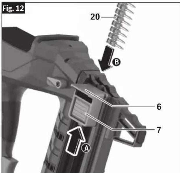
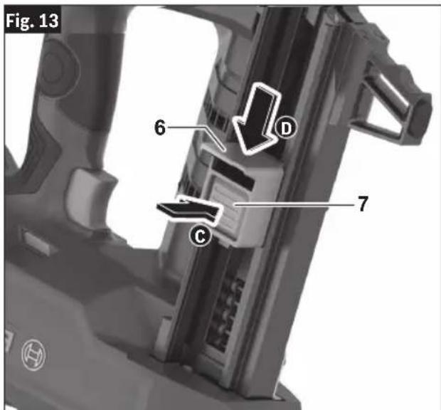
Loading Collated Magazine
(Fig. 12, 13)
When loading the collated magazine, check that the Magazine Slider 6 slides smoothly. If the Magazine Slider 6 does not slide smoothly, nails can be driven at irregular angle or the nailer may blank-fire.
Use fastener strips that are unbroken and have fasteners of the same designation.
Loading Instructions:
WARNING
Do not pull the trigger or depress the nosepiece when
loading the nailer. Pulling the trigger or depressing the nosepiece may cause misfiring of the tool resulting in personal injury and property damage.
- Remove the Battery Pack.
- Ensure that the Collated Magazine 5 is free of debris, such as a build-up of concrete dust.
- Install the Collated Magazine 5 and the Collated Nosepiece 8 according to instructions in the section "Removing and Installing the Magazine and Nosepiece".
- Position nailer onto a flat stable surface and point the Nosepiece 8 away from yourself and bystanders.
- Pull the Magazine Slider 6 to the end of the magazine until it locks in place A.
- Insert collated nail strip(s) 20 with the heads of the fasteners at the top of the magazine slot, as shown in Fig. 12. Confirm that the nails have slid to the front of the Collated Magazine 5 B.
Note: The standard collated magazine can receive a maximum of 2 nail strips. The extended collated magazine can receive a maximum of 4 nail strips.
- While holding Magazine Slider 6 firmly, press the Magazine Slider Button 7 and carefully slide the Magazine Slider 6 to ensure nail strips are secured.
WARNING
Guide the magazine slider by hand until it reaches its
full forward position. Free recoil of the Magazine Slider can result in damage the follower, magazine, or cause personal injury.
Note: For best performance use Bosch branded nails as listed in the "Fastener Selection" section.
Dry Fire Lock Out
The nailer is equipped with a Dry Fire Lock Out. The Dry Fire Lock Out prevents firing when there are 2 fasteners remaining in the collated magazine.
Operation
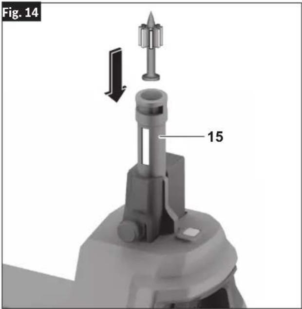
Loading Single Shot Fasteners
(Fig. 2, 14)
Loading Instruction
WARNING
Do not pull the trigger or depress the nosepiece when
loading the nailer. Pulling the trigger or depressing the nosepiece may cause misfiring of the tool resulting in personal injury and property damage.
CAUTION
Load only one single shot fastener at a time. Loading
multiple fasteners can cause misfiring and damage the nailer.
- Remove the Battery Pack.
- Ensure that the Single Shot Magazine 14 is free of debris, such as a build-up of concrete dust.
- Install the Single Shot Nosepiece 15 and the Single Shot Magazine 14 according to instructions in the section "Removing and Installing the Magazine and Nosepiece".
- Position nailer onto a flat stable surface and point the Nosepiece 15 away form yourself and bystanders.
- Select and push a single shot fastener into the Single Shot Nosepiece 15 as shown in Fig 14.
Note: Compatible single shot fasteners are 0.300" (8mm) nominal diameter, as shown in the "Specifications" table. The fastener should slide easily into the Single Shot Nose-piece 15 and not fall out.
Operation
User Interface
(Fig. 15)
The User Interface 1 provides the following functions:
a ON/OFF Button
b Status Indicator
c Battery Charge Indicator
d Reset Button
ON/OFF Button
To switch ON the nailer, press the ON/OFF Button 1a on the User Interface 1 for 1.5 seconds until the Warning Indicator 1b and Battery Charge Indicator 1c lights turn on.
To switch OFF the nailer, press the ON/OFF button 1a again.
The nailer will switch off after 30 minutes of inactivity.
Status Indicator
The Status Indicator 1b shows the status of the nailer. A green light indicates that the nailer is ready for operation. In case the Status Indicator light color is not green, consult the “Trouble Shooting” section for further information.
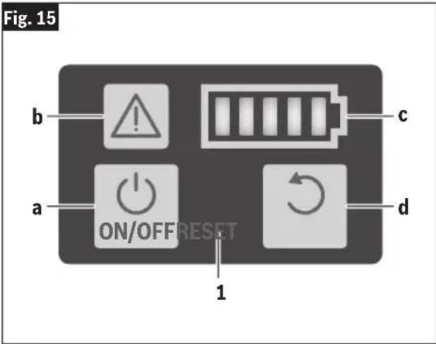
Battery Charge Indicator
The Battery Charge Indicator 1c shows the state of charge of the battery.
| LED Capacity | |
| 5 × continuous green light 80– | 100 % |
| 4 × continuous green light 60– | 80 % |
| 3 × continuous green light 40– | 60 % |
| 2 × continuous green light 20– | 40 % |
| 1 × continuous green light 5– | 20 % |
| 1 × flashing green light 0–5 % |
Reset Button
The Reset Button 1d is used to reset the nailer to a normal state after an abnormal condition is corrected. To reset the nailer, press the reset button for 3 seconds.
Consult the "Trouble Shooting" section for further information on resetting of the nailer.
Operation
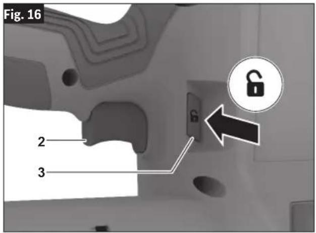
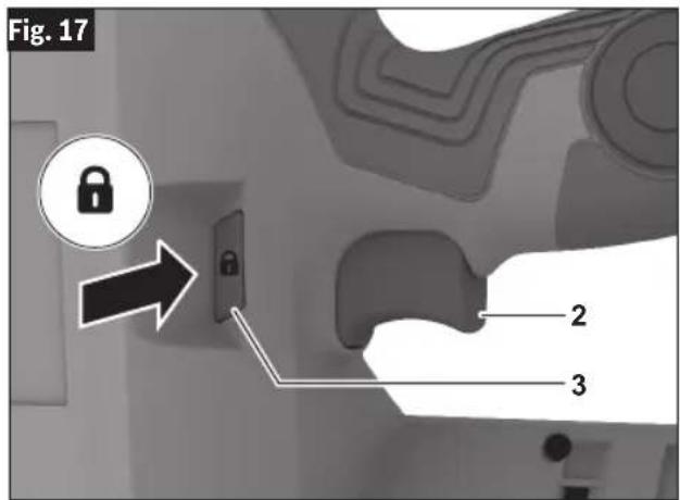
Trigger Lock
(Fig. 16, 17)
The Trigger Lock 3 is designed to prevent unintended trigger activation.
To Unlock the Trigger:
Fully press the Trigger Lock 3 on the unlock symbol side to unlock the Trigger 2 (Fig. 16).
To Lock the Trigger:
Release the Trigger 2, and fully press the Trigger Lock 3 on the lock symbol side to lock the Trigger 2 (Fig. 17).
Built-in Work Light
(Fig. 1)
Your nailer is equipped with an LED Work Light 13 for better visibility when using the nailer.
The LED will stay on for 10 seconds after the Trigger 2 is pressed.
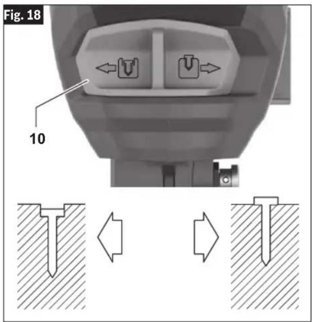
Depth of Drive Adjustment
(Fig. 18)
The depth to which fasteners are driven into the work piece can be adjusted using the Depth Setting Switch 10 on the front of the nailer.
Slide the Depth Setting Switch 10 to the left to increase the drive depth, as seen in (Fig. 18).
Slide the Depth Setting Switch 10 to the right to reduce drive depth, as seen in (Fig. 18).
Operation
Nailer Actuation
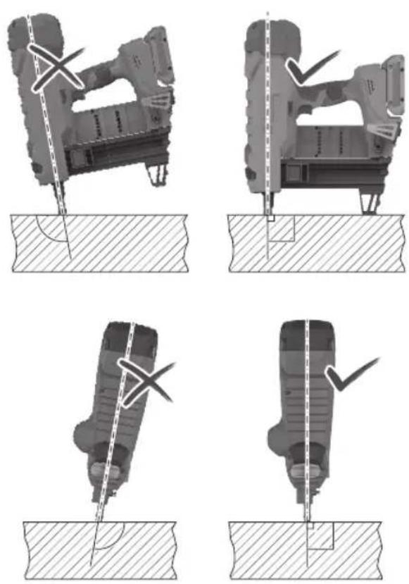
WARNING
Nosepiece must be in full contact with the work sur-
face. Gap between the nosepiece and the work surface may result in deflection of the fastener and property damage or personal injury.
WARNING
Never wedge the nosepiece between two or more sur-
faces. Gap between the nosepiece and multiple work surfaces may allow deflection of the fastener and property damage or personal injury.
WARNING
Never hold back the nose-piece during operation.
Holding the nosepiece back can result in unexpected actuation and may cause property damage or serious injury.
WARNING
Never position your face or body over the nailer top cap
during operation. Sudden recoil can result in impact to the body and injury.
This nailer operates only in a fully sequential mode, steps 5–7 must be repeated sequentially for intended operation of the nailer.
(Fig. 19, 20)
Assemble the needed Nosepiece and Magazine as described in the “Removing and Installing the Magazine and Nosepiece” section.
- Insert the Battery Pack.
- Press and hold the ON/OFF Button to activate the nailer.
- Press the Trigger Lock 3 to unlock the Trigger 2 (Fig. 19).
- Firmly grip of the nailer's handle and hold the nailer perpendicular (90° angle) to the work surface (Fig. 20), and use your free hand to hold the top cap for added stability.
-
Press the Nosepiece 8, 15 A fully against the work surface. If the Nosepiece is not fully pressed into the nailer, the nailer will not fire.
-
Press the Trigger 2 B to drive the fastener into the worksurface. The trigger has to be pressed within 2 seconds after the Nosepiece is fully pressed. If the trigger is pressed later, the nailer will revert to a SAFE mode and the actuation sequence will have to be repeated.
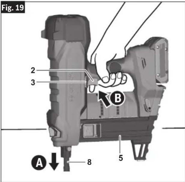
Fig. 20
natural_image
Four technical diagrams showing mechanical assembly steps with no visible text or symbolsOperation
The nailer will recoil after the fastener is driven into the work surface. Use sufficient grip to maintain control and alignment of the nailer with the work surface during firing and recoil.
- Release the Trigger 2 and pull the nailer away from the work surface.
To fire another fastener the Trigger and Nosepiece must be released and the firing sequence, steps 5-7, repeated.
Note: The nailer will switch off after 30 minutes of inactivity.
Maintenance
WARNING
To avoid accidents, always disconnect the Battery Pack from the tool before cleaning or performing any maintenance.
WARNING
Do not point the tool towards yourself or anyone nearby. Unexpected triggering will discharge the fastener causing an injury.
General Maintenance
Keep your nailer, battery pack and charger in good working order by adopting a regular maintenance program. Inspect your nailer for issues such as undue noise, misalignment or binding of moving parts, breakage of parts, or any other condition that may affect the nailer operation.
This nailer does not contain user-serviceable parts. The gas reservoir should be recharged only by an authorized service provider.
It is recommended after 6 months to a year, depending on use, to return the nailer, battery pack and charger to a BOSCH service facility for inspection.
If the nailer does not start or operate at full power with a fully charged battery pack, clean the contacts on the battery pack. If the nailer still does not work properly, return the nailer, charger and battery pack, to a BOSCH service facility for repairs.
Service
WARNING
NO USER SERVICEABLE PARTS INSIDE. Maintenance
performed by un au thorized personnel may result in misplacing of internal wires and components which could cause serious hazard. We recommend that all tool service be performed by a Bosch Factory Service Center or Authorized Bosch Service location.
Cleaning
Clean dust and debris from any vents and fast-ner magazines. Keep nailer clean, dry and free of oil or grease. Use only mild soap and a damp cloth to clean housing, since certain cleaning agents and solvents are harmful to plastics and other insulated parts. Some of these include gasoline, turpentine, lacquer thinner, paint thinner, chlorinated cleaning solvents, ammonia and household detergents containing ammonia. Never use flammable or combustible solvents around tools.
Remove collation plastic and clean accumulated dust from the magazine to allow the fasteners to feed smoothly.
Repairs
For repairs, return the nailer, battery pack and charger to the nearest Bosch service center, or Authorized Bosch Service location.
Accessories
WARNING
Do not use attachments/accessories other than those specified by Bosch. Use of attachments/accessories not specified for use with the tool described in this in damage to tool, property damage, and or personal injury.
| Item Catalog Number | |
| Extended Magazine GNB44M |
Troubleshooting
WARNING
Disconnect battery pack from tool before assembly, adjustments, troubleshooting or changing accessories. Such preventive safety measures reduce the tool accidentally, which may result in personal injury.
risk of starting the tool accidentally, which may result in personal injury.
Jam Clearing
Follow the Jam clearing procedure when the error state shows the following indicator (RED) (ORANGE), or the tool no longer fires correctly.
-
After the tool indicates that there is a jam, remove the battery from the nailer.
-
Remove the magazine, all fasteners, as well as the Nosepiece.
Note: Jams can be cleared from the Nose-piece without the need to handle the driver blade.
- Check the magazine; inspect and clear the magazine of jams, this can include:
a. Residual collation material build-up.
b. Foreign matter preventing normal operation.
- Check the Nosepiece.
Using a thin rod (approx 1/4" or 6mm) push out any nails, nail fragments, collation material, or foreign material inhibiting normal operation.
-
Reassemble the tool with the nosepiece and corresponding magazine without fasteners, then insert the battery pack and turn ON the nailer.
-
On HMI press the Reset Button for 3 sec to enter the reset mode.
To retract the driver blade back to its correct position and allow the motor to operate:
If using the Collated Magazine, pull the fol- lower back before pressing the Nosepiece against a wood block or similar and pull the trigger.
If using Single Shot Magazine, press the Nosepiece against a wood block or similar and pull the trigger.
-
If other abnormal conditions are encountered during the mechanical reset of the driver blade, then the status indicator will display the appropriate status light color.
-
After successfully resetting the nailer to normal status, follow the "Daily Inspection and Testing" to ensure normal operation of the nailer.
Troubleshooting
| Status Light Color | Status Condition User Action | ||
| GREEN NORMAL | Nailer is energized and operating conditions are normal | Nailer is ready for use | |
| RED | Jam condition detected | The driver blade cannot return to correct position | 1) Follow the “Jam clearing” sequence to remove the obstruction in the Nosepiece or Magazine.2) In the RESET mode, if other abnormal conditions are encountered, the status indicator will display the appropriate status light color. |
| YELLOW | Motor and Electronics Overheat protection | Motor or electronics temperature is above 50°F (122°C). | Allow the nailer to cool. When the motor and electronics cool sufficiently, the nailer will self reset and resume normal operation. |
| DARK BLUE | Nailer Low Temperature Protection | Nailer temperature is lower than 23°F (-5°C). | Place nailer in warm space. When the motor and electronics warm sufficiently, the nailer will self reset and resume normal operation. |
| ORANGE | Motor Blocked - Motor cannot return driver blade to correct position | Drive mechanism is obstructed, preventing normal reset operation. | 1) Follow the “Jam clearing” sequence to remove the obstruction in the Nosepiece or Magazine.2) In the RESET mode, if other abnormal conditions are encountered, the status indicator will display the appropriate status light color. |
| LIGHT BLUE | Motor Overcurrent Protection | Motor is drawing excessive current - Nailer will stop operation. | 1) If nailer is being fired for extended periods without sufficient cooling, allow the nailer to cool.2) Examine nailer for obstruction or excessive contamination.3) Error will clear if battery is removed or nailer is turned OFF.4) If error persists, nailer needs to be returned for repair at a Bosch service center. |
| WHITE | Electronics Fault - Nailer in SAFE mode | Electronics fault detected preventing operation. | This condition is Non-resettable and non-repairable by user. Nailer needs to be returned for repair at a Bosch service center. |
| MAGENTA | Service Recommended | Service-indicator illuminates MAGENTA for 3 seconds, then shows normal green. | Return to Bosch service center for service. |
Troubleshooting
| Trouble Cause Action | ||
| Nailer does not operate,No actuation occurs | No battery inserted, battery discharged Insert charged battery | |
| Battery and tool temperature too low | Allow battery and tool to warm up sufficiently to operating ambient temperature | |
| Nailer not switched on Press ON/OFF button for 1.5 seconds | ||
| Sequential operation has not been conducted correctly | See “Nailer Actuation” section | |
| Trigger Lock in locked position Press Trigger | Lock to unlock position | |
| Dry Fire Lock Out activated, only two nails left in collated magazine | Insert nails into collated magazine | |
| Fastener jammed in Nosepieceor Nosepiece remains in pressed position | Debris, dirt, or jammed nail,in Nosepiece | See “Jam Clearing” section |
| Underdriven fasteners | Not enough setting energy | Adjust Depth Setting Switch to increase drive depth |
| Fastener is too long | Select shorter nail per “Fastener Selection” table. | |
| Work surface too hard Use different fastening method | ||
| Overdriven fasteners | Too much setting energy | Adjust Depth Setting Switch to decrease drive depth |
| Fastener is too short | Select longer nail per “Fastener Selection” table | |
| Work surface too soft Use different fastening method | ||
| Fasteners bend or break | Fastener is too long | Select shorter nail per “Fastener Selection” table |
| Work surface too hard Use different fastening method | ||
| Nailer not perpendicular to work surface See “Nailer Actuation” section | ||
| Fasteners do not hold in steel Steel work piece too thin Use different fastening method | ||
| Fastener failure rate is too high | Work surface too hard Use different fastening method | |
| Driver blade is worn | Take the nailer to an authorized service center | |
| Fasteners do not slide into magazine | Dust or debris in magazine See “Jam Clearing” section | |
Safety Warnings for Cordless Nailer Tools....30
MISE AU REBUT DES PILES
AVERTISSEMENT
Symboles
natural_image
Technical illustration of a mechanical bracket assembly with labeled parts (12 and 14), no readable text or symbols beyond labelsSeparate all parts from the packing materials, and check each one with the illustration and the list of loose parts to make certain all items are accounted for before discarding any packing material.
natural_image
3D model of a mechanical device with labeled component A, no visible text or symbols on the body itself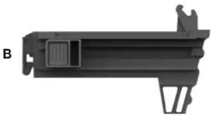
natural_image
3D rendered mechanical component with no visible text or symbols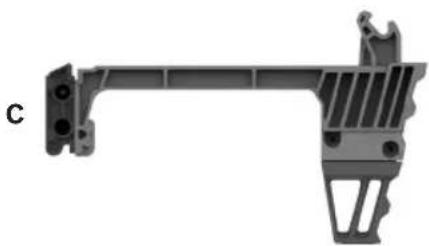
natural_image
Mechanical bracket component with mounting holes and internal structure (no text or symbols visible)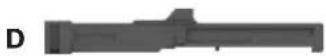

natural_image
3D model of a black plastic housing component with cutouts and mounting holes, labeled F and G (no text or symbols on the object itself)Assemblage
AVERTISSEMENT
natural_image
Mechanical assembly diagram showing a component being inserted into a housing, with a numbered arrow indicating the process (no text or symbols present)Do not pull the trigger or depress the nose-
piece when loading the nailer. Pulling the trigger or depressing the nosepiece may cause misfiring of the tool resulting in personal injury and property damage.
MISE EN GARDE
Load only one single shot fastener at a time. Loading
multiple fasteners can cause misfiring and damage the nailer.
Never wedge the nosepiece between
two or more surfaces. Gap between the nosepiece and multiple work surfaces may allow deflection of the fastener and property damage or personal injury.
AVERTISSEMENT
Never hold back the nosepiece during op-
eration. Holding the nosepiece back can result in unexpected actuation and may cause property damage or serious injury.
AVERTISSEMENT
Never position your face or body over the
nailer top cap during operation. Sudden recoil can result in impact to the body and injury.
natural_image
Four technical diagrams showing mechanical assembly steps with no visible text or symbolsPIÈCE SUSCEPTIBLE D'ÊTRE ENTRE TENUE PAR
Símbolos
natural_image
Technical illustration of a mechanical bracket assembly with labeled parts (12 and 14), no text or symbols present.natural_image
3D model of a mechanical component with labeled parts (no readable text or symbols)
natural_image
3D model of a mechanical component with labeled part B, showing internal structure and mounting bracket (no text or symbols beyond label)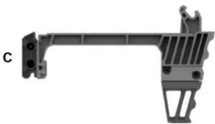
natural_image
Mechanical bracket component with mounting holes and internal structure (no text or symbols visible)


natural_image
3D model of a mechanical part with cutouts and a small connector (no text or symbols visible)Ensamblaje
ADVERTENCIA
natural_image
Mechanical assembly diagram showing a robotic arm and a mechanical component with a numbered arrow indicating motion (no text or symbols present)Do not pull the trigger or depress the nosepiece
when loading the nailer. Pulling the trigger or depressing the nosepiece may cause misfiring of the tool resulting in personal injury and property damage.
natural_image
Four technical diagrams showing a robotic arm performing a tool on a workpiece, with no visible text or symbols.Operación
This page was intentionally left blank
This page was intentionally left blank
Limited Warranty of Bosch Portable and Benchtop Power Tools ("Limited Warranty")
Robert Bosch Tool Corporation ("Bosch", "we" or "our") warrants to the original end-user purchaser only that each BOSCH-branded portable and benchtop power tool and battery (each, a "Product") will be free from defects in material or workmanship for the period of time listed in the chart below for the "Product Category" applicable for such Product (as applicable, the "Warranty Period"):
| Product Category Warranty Period | ____ |
| 18V Cordless Power Tools, 18V Benchtop Power Tools and 18V Chargers Five (5) years from the date of purchase | |
| 18V Power Tool Batteries Three (3) years from the date of purchase | |
| 12V Cordless Power Tools and 12V Chargers One (1) year from the date of purchase | |
| 12V Power Tool Batteries One (1) year from the date of purchase | |
| Corded Portable Power Tools and Corded Benchtop Power Tools One (1) year from the date of purchase |
OUR SOLE OBLIGATION AND YOUR EXCLUSIVE REMEDY under this Limited Warranty and, to the extent permitted by law, under any warranty or condition implied by law, shall be the repair or replacement of parts, without charge, which are defective in material or workmanship and which have not been abused, misused, carelessly handled, or repaired by persons other than Bosch or a Bosch Authorized Service Center.
Normal wear and tear of your Product is not covered by this Limited Warranty. As a result, Product parts that may become worn or exhausted over time due to normal wear and tear (including, without limitation, air filters, blade clamps, brushes, bumpers, bumper cover washers, chucks, cords, driver belts, driver blades, isolators, lifters, o-rings, pistons, piston/driver assemblies, piston stops, saw shoes, seals, strikers, etc.), or any other service or repairs required due to normal wear and tear on a Product, are not covered by this Limited Warranty.
To make a claim under this Limited Warranty, you must return the complete Product, transportation prepaid, to any Bosch Factory Service Center or Bosch Authorized Service Center. Please include a dated proof of purchase with your Product so we can determine if your Product is within the Warranty Period. If you do not have the dated proof of purchase for the Product that is the subject of your claim, we will use the Product's production code to determine whether the Product is within the Warranty Period. For locations of nearby Bosch Factory Service Centers or Bosch Authorized Service Centers, please use our service locator at https://www.boschtools.com/us/en/service/service-center-locator/. For more information on Limited Warranty performance, please contact our customer service at 1-877-267-2499.
THIS LIMITED WARRANTY DOES NOT APPLY TO BOSCH®-BRANDED:
(i) MEASURING TOOLS,
(ii) ACCESSORY ITEMS SUCH AS CIRCULAR SAW BLADES, DRILL BITS, ROUTER BITS, JIGSAW BLADES, SANDING BELTS, GRINDING WHEELS AND OTHER SIMILAR TYPES OF ITEMS; OR
(iii) CARRYING CASES OR CARRYING BAGS.
ANY IMPLIED WARRANTIES FOR A PRODUCT SHALL BE LIMITED IN DURATION TO THE SHORTER OF (i) THE APPLICABLE WARRANTY PERIOD FOR SUCH PRODUCT/PRODUCT CATEGORY LISTED ABOVE, OR (ii) SUCH DURATION AS WOULD OTHERWISE APPLY UNDER APPLICABLE LAW IF THIS LIMITED WARRANTY WERE NOT OFFERED BY BOSCH. SOME STATES IN THE U.S., AND SOME CANADIAN PROVINCES, DO NOT ALLOW LIMITATIONS ON HOW LONG AN IMPLIED WARRANTY LASTS, SO THE ABOVE LIMITATION MAY NOT APPLY TO YOU.
IN NO EVENT SHALL BOSCH BE LIABLE FOR ANY INCIDENTAL OR CONSEQUENTIAL DAMAGES (INCLUDING BUT NOT LIMITED TO LIABILITY FOR LOSS OF PROFITS) ARISING FROM THE SALE OR USE OF THIS PRODUCT. SOME STATES IN THE U.S. AND SOME CANADIAN PROVINCES (INCLUDING, WITHOUT LIMITAITON, QUEBEC) DO NOT ALLOW THE EXCLUSION OR LIMITATION OF INCIDENTAL OR CONSEQUENTIAL DAMAGES, SO THE ABOVE LIMITATION OR EXCLUSION MAY NOT APPLY TO YOU.
THIS LIMITED WARRANTY GIVES YOU SPECIFIC LEGAL RIGHTS, AND YOU MAY ALSO HAVE OTHER RIGHTS WHICH VARY FROM STATE TO STATE IN THE U.S., PROVINCE TO PROVINCE IN CANADA AND FROM COUNTRY TO COUNTRY.
THIS LIMITED WARRANTY APPLIES ONLY TO PRODUCTS SOLD WITHIN THE UNITED STATES OF AMERICA AND CANADA. FOR WARRANTY COVERAGE WITHIN OTHER COUNTRIES, CONTACT YOUR LOCAL BOSCH® BRAND TOOL DEALER OR IMPORTER.
V202211
© Robert Bosch Tool Corporation
1800 W. Central Road
Mt. Prospect, IL 60056-2230
1605A001CD 01/2023