Micro IR200 - Measuring equipment RIDGID - Free user manual and instructions
Find the device manual for free Micro IR200 RIDGID in PDF.

| Product Type | Infrared Remote Thermometer |
| Brand | RIDGID |
| Model | Micro IR-200 |
| Category | Measurement Equipment |
| Temperature Range | -50°C to 1200°C (-58°F to 2192°F) |
| Accuracy | ±1% or ±1.0°C (20°C to 800°C) |
| Distance to Spot Ratio | 30:1 |
| Display Resolution | 0.1°C |
| Response Time | 150 ms |
| Spectral Response | 8 to 14 µm |
| Adjustable Emissivity | 0.10 to 1.00 |
| Aiming Laser | Dual Class 2 Laser, power <1mW, wavelength 630-670 nm |
| Display | LCD with Backlight |
| Power Supply | 1 9V battery (type NEDA 1604a, IEC 6LR61) |
| Weight | 300 g (0.6 lb) |
| Protection Rating | IP54 |
| Operating Temperature | 0°C to 50°C |
| Storage Temperature | -10°C to 60°C |
| Main Functions | Non-contact measurement, continuous scanning, high and low temperature alarms, max temperature memory, °C/°F unit selection |
| Maintenance and Cleaning | Wipe with a damp soft cloth; do not immerse |
| Safety | Do not look into the laser beam; Class 2 laser |
| Spare Parts and Repairability | Contact an authorized RIDGID repair center |
| General Information | Lifetime warranty (conditions apply) |
Frequently Asked Questions - Micro IR200 RIDGID
User questions about Micro IR200 RIDGID
0 question about this device. Answer the ones you know or ask your own.
Ask a new question about this device
Download the instructions for your Measuring equipment in PDF format for free! Find your manual Micro IR200 - RIDGID and take your electronic device back in hand. On this page are published all the documents necessary for the use of your device. Micro IR200 by RIDGID.
USER MANUAL Micro IR200 RIDGID
Recording Form for Machine Serial Number ....1
Safety Symbols....2
General Safety Rules
Work Area Safety....3
Electrical Safety....3
Personal Safety....3
Equipment Use and Care 3
Service....4
Specific Safety Information
Infrared Thermometer Safety....4
Description, Specifications and Standard Equipment
Description....4
Specifications 4
Parts 6
LCD Display Icons 6
Standard Equipment....6
Laser Classification 7
FCC Statement....7
Electromagnetic Compatibility (EMC) 7
Changing/Installing Batteries....7
Pre-Operation Inspection....8
Set-Up and Operation
Set-Up 9
Operation
Turning ON and OFF (Taking Measurements)......10
micro IR-200 Controls
Continuous Measurement (Scanning) Mode 10
Laser Enabled/Disabled....10
Backlight 11
Menu Button Use 11
High Alarm 11
Low Alarm 11
Temperature Display Units-C/F 11
Emissivity 11
Cleaning....11
Storage 11
Service and Repair 12
Disposal 12
Battery Disposal 12
EC Declaration of Conformity ....Inside Back Cover
Lifetime Warranty ....Back Cover
*Original Instructions - English
micro IR-200
micro IR-200 Non-Contact Infrared Thermometer
text_image
RIDGID 317 - 318 micro IR-200
WARNING!
Read this Operator's Manual carefully before using this tool. Failure to understand and follow the contents of this manual may result in electrical shock, fire and/or serious personal injury.
| micro IR-200 Non-Contact Infrared Thermometer | |
| Record Serial Number below and retain product serial number which is located on nameplate. | |
| Serial No. | |
Safety Symbols
In this operator's manual and on the product, safety symbols and signal words are used to communicate important safety information. This section is provided to improve understanding of these signal words and symbols.

This is the safety alert symbol. It is used to alert you to potential personal injury hazards. Obey all safety messages that follow this symbol to avoid possible injury or death.

DANGER indicates a hazardous situation which, if not avoided, will result in death or serious injury.

WARNING indicates a hazardous situation which, if not avoided, could result in death or serious injury.

CAUTION indicates a hazardous situation which, if not avoided, could result in minor or moderate injury.

ICE NOTICE indicates information that relates to the protection of property.

This symbol means read the operator's manual carefully before using the equipment. The operator's manual contains important information on the safe and proper operation of the equipment.

This symbol means this device contains a Class 2 Laser.

This symbol means do not stare into the laser beam.

This symbol warns of the presence and hazard of a laser beam.
General Safety Rules
WARNING
Read all safety warnings and in struc tions. Failure to follow the warn ings and instructions may result in electric shock, fire and/or serious injury.
SAVE THESE INSTRUCTIONS!
Work Area Safety
- Keep your work area clean and well lit. Cluttered or dark areas invite accidents.
- Do not operate equipment in explosive atmospheres, such as in the presence of flammable liquids, gases or dust. E - equipment can create sparks which may ignite the dust or fumes.
- Keep children and by-standers a way while operating equipment. Distrac tions can cause you to lose control.
Electrical Safety
- Avoid body contact with earthed or grounded surfaces such as pipes, radiators, ranges and refrigerators. There is an increased risk of electrical shock if your body is earthed or grounded.
- Do not expose equipment to rain or wet conditions. Water entering equipment will increase the risk of electrical shock.
Personal Safety
- Stay alert, watch what you are doing and use common sense when operating equipment. Do not use equipment while you are tired or under the influence of drugs, alcohol or medication. A moment of inattention while operating equipment may result in serious personal injury.
- Use personal protective equipment. Always wear eye protection. Protective equipment such as dust mask, non-skid safety
shoes, hard hat, or hearing protection used for appropriate conditions will reduce personal injuries.
- Do not overreach. Keep proper footing and balance at all times. This enables better control of the power tool in unexpected situations.
Equipment Use and Care
- Do not force equipment. Use the correct equipment for your application. The correct equipment will do the job better and safer at the rate for which it is designed.
- Do not use equipment if the switch does not turn it ON and OFF. Any tool that cannot be controlled with the switch is dangerous and must be repaired.
- Disconnect the batteries from the equipment before making any adjustments, changing accessories, or storing. Such preventive safety measures reduce the risk of injury.
- Store idle equipment out of the reach of children and do not allow persons unfamiliar with the equipment or these instructions to operate the equipment. Equipment can be dangerous in the hands of untrained users.
- Maintain equipment. Check for misalignment or binding of moving parts, missing parts, breakage of parts and any other condition that may affect the equipment's operation. If damaged, have the equipment repaired before use. Many accidents are caused by poorly maintained equipment.
- Use the equipment and accessories in accordance with these instructions, taking into account the working conditions and the work to be performed. Use of the equipment for operations different from those intended could result in a hazardous situation.
- Use only accessories that are recommended by the manufacturer for your equipment. Accessories that may be suitable
RIDGID
micro IR-200 Non-Contact Infrared Thermometer
for one piece of equipment may become hazardous when used with other equipment.
- Keep handles dry and clean; free from oil and grease. Allows for better control of the equipment.
Service
- Have your equipment serviced by a qualified repair person using on ly identical replacement parts. This will ensure that the safety of the tool is maintained.
Specific Safety Information
WARNING
This section contains important safety information that is specific to this tool.
Read these precautions carefully before using the RIDGID micro IR-200 Non-Contact Infrared Thermometer to reduce the risk of eye injury or other serious personal injury.
SAVE THESE INSTRUCTIONS!
Keep this manual with the tool for use by the operator.
Infrared Thermometer Safety
- Do not look into the laser beam. Looking into the laser beam may be hazardous to the eyes. Do not look at the laser beam with optical aids (such as binoculars or telescopes).
- Do not direct the laser beam towards other people. Make sure the laser is aimed above or below eye level. Laser beams may be hazardous to the eyes.
- Do not use this device for personal inspection or medical use in any way. This is not a medical device. This could cause personal injury.
• Take appropriate precautions when working near electrical, moving or hot parts. Close contact may cause electrical shock, entanglement, burns and other serious injury. Protective equipment may be required.
CAUTION Use of controls or adjustments or performance of procedures other than those specified herein may result in hazardous radiation exposure.
If you have any question concerning this RIDGID product:
- Contact your local RIDGID distributor.
- Visit RIDGID.com to find your local RIDGID contact point.
- Contact Ridge Tool Technical Service Department at rtctechservices@emerson.com, or in the U.S. and Canada call (800) 519-3456.
Description, Specifications And Standard Equipment
Description
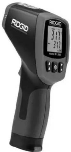
The RIDGID® micro IR-200 Non-Contact Infrared Thermometer provides simple, quick, and accurate surface temperature readings at the push of a button. You simply squeeze the trigger and point the ultra-sharp dual class II lasers at the surface being measured. The micro IR-200 provides an immediate temperature measurement on a clear, easy-to-read backlit LCD display. In addition to numerous other uses, this rugged, compact instrument enables professional tradesman to diagnose heating and ventilation problems, perform preventative monitoring of electrical motors and systems, troubleshoot steam traps and quickly check fuses or circuit breakers for overheating without contact.
The micro IR-200 uses optics to sense emitted, reflected and transmitted energy, which is collected and focused onto a detector. The unit's electronics translate the information into a temperature reading, which is displayed. Lasers are used to assist in aiming.
Specifications
| Temperature Range | -58°F to 2192°F(-50°C to 1200°C) |
| Distance To Spot Ratio | 30 to 1 |
| Measuring Accuracy | -58°F ~68°F (-50°C ~20°C): ±4.5°F (2.5°C)68°F ~1472°F (20°C ~800°C)±1.0% or ±1.8°F (1.0°C) |
| Repeatability | -58°F ~68°F (-50°C ~20°C): ±2.3°F (1.3°C)68°F ~1472°F (20°C ~800°C)±0.5% or ±0.9°F (0.5°C) |
Response Time ....150ms
Spectral Response....8\~14um
Emissivity ....Adjustable, 0.10 - 1.00
Over Range Indication ....LCD will show “----”
Diode Laser ...... Output <1mW, Wavelength 630\~670nm, Class 2 Laser Product
Temperature Display ....Current Temperature, MAX Temperature
Measuring Units....Fahrenheit, Celsius
Operating Temperature ....32°F to 122°F (0°C to 50°C)
Storage Temperature ....14°F to 140°F (-10°C to 60°C)
Display Resolution ....0.1°F (0.1°C)
Relative Humidity....10%\~90% RH Operating, <80% RH Storage
Batteries....9V Battery (1), NEDA 1604A or IEC 6LR61, or Equivalent
IP Rating.....IP54
Weight....0.6 lbs (0.3 kg)
Features
- Rapid Detection Function
• Dual Class II Laser Sighting
• Automatic Data Hold
• MAX Temperature Displays
- Precise Non-Contact Measurements
• Automatic Selection Range and Display Resolution 0.1°F (0.1°C)
natural_image
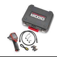
RiGIO medical scanner with a black case and a small electronic device beside it (no visible text or symbols on the device body)Figure 1 – micro IR-200 Non-Contact Infrared Thermometer
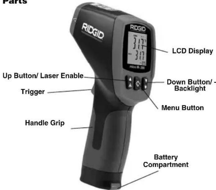
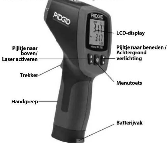
Parts
text_image
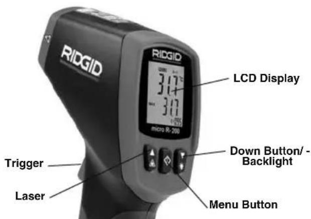
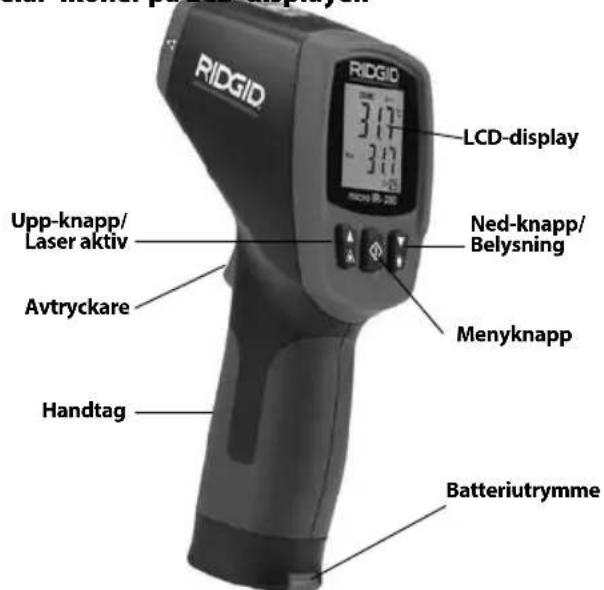
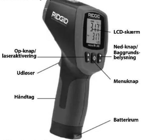
Parts RIDGID LCD Display 3.17" -3.00" micro IR-200 Up Button/ Laser Enable Trigger Handle Grip Down Button/ Backlight Menu Button Battery CompartmentFigure 2 – micro IR-200 Parts
text_image
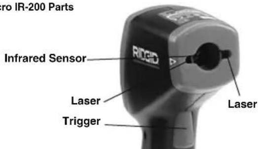
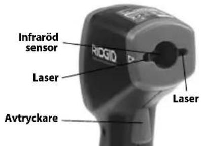
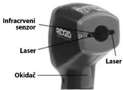
ro IR-200 Parts Infrared Sensor RIGID Laser Trigger LaserLCD Display Icons
text_image
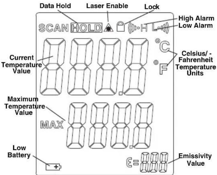
Data Hold Laser Enable Lock SCAN HOLD High Alarm Low Alarm Current Temperature Value Celsius/ - Fahrenheit Temperature Units Maximum Temperature Value MAX Low Battery + Emissivity ValueFigure 3 – micro IR-200 Display Icons
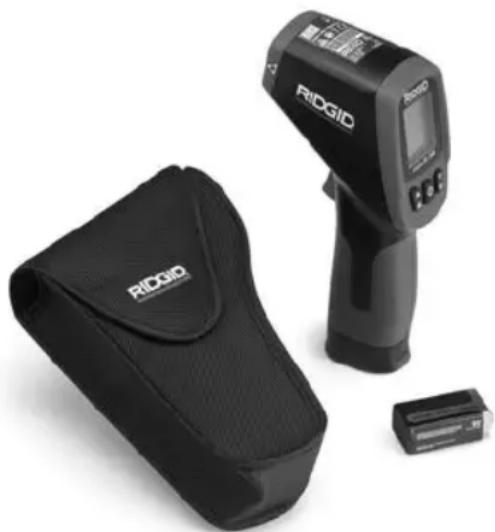
Standard Equipment
- micro IR-200
-
Carrying Case
-
Battery 1 × 9V
- Operator's Manual
NOTICE This equipment is used to make temperature measurements. Incorrect use or improper application may result in incorrect or inaccurate measurements. Selection of appropriate measurement methods for the conditions is the responsibility of the user.
Laser Classification

The RIDGID micro IR-200 generates a visible laser beam that is emitted from the front of the device.
The device complies with class 2 lasers according to: IEC 60825-1:2007
FCC Statement
This equipment has been tested and found to comply with the limits for a Class B digital device, pursuant to part 15 of the FCC Rules. These limits are designed to provide reasonable protection against harmful interference in a residential installation.
This equipment generates, uses, and can radiate radio frequency energy and, if not installed and used in accordance with the instructions, may cause harmful interference to radio communications.
However, there is no guarantee that interference will not occur in a particular installation.
If this equipment does cause harmful interference to radio or television reception, which can be determined by turning the equipment off and on, the user is encouraged to try to correct the interference by one or more of the following measures:
- Reorient or relocate the receiving antenna.
- Increase the separation between the equipment and receiver.
- Consult the dealer or an experienced radio/TV technician for help.
Electromagnetic Compatibility (EMC)
The term electromagnetic compatibility is taken to mean the capability of the product to function smoothly in an environment where electromagnetic radiation and electrostatic discharges are present and without causing electromagnet interference to other equipment.
NOTICE The RIDGID micro IR-200 conforms to all applicable EMC standards. However, the possibility of it causing interference in other devices cannot be precluded.
natural_image
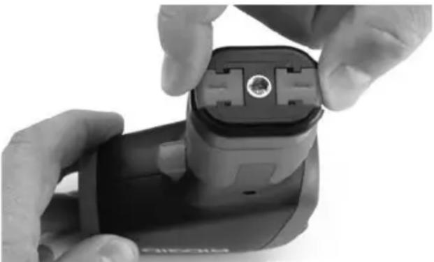
Close-up of hands installing a black plastic electrical plug into a device (no visible text or symbols)Figure 4 – Removing Battery Compartment
Changing/Installing Batteries
The micro IR-200 is supplied without a battery installed. If the battery indicator (Figure 3) displays ☐, the battery needs to be replaced. Remove the battery prior to long term storage to avoid battery leakage.
- Squeeze the battery clips and remove battery compartment from the thermometer (See Figure 4). If needed, remove battery.

micro IR-200 Non-Contact Infrared Thermometer
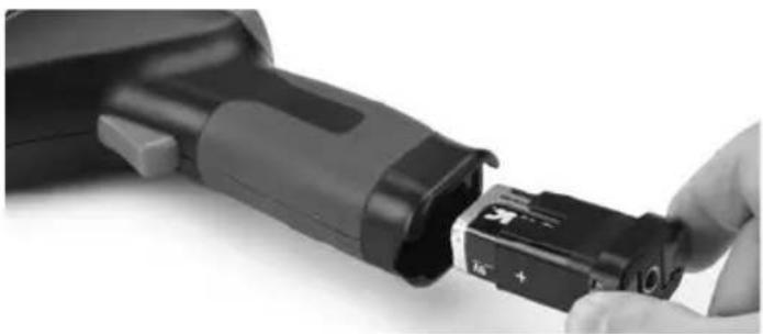
- Install 9V alkaline battery (6LR61), observing the correct polarity as indicated on the battery compartment.
natural_image
Close-up of a hand inserting a black plastic component into a black housing (no text or symbols visible)Figure 5 – Battery Holder and Polarity Marking
- Squeeze the clips and firmly insert into thermometer. The holder will only go in one way. Do not force. Confirm securely attached.
Pre-Operation Inspection
WARNING
Before each use, inspect your infrared thermometer and correct any problems to reduce the risk of injury or incorrect measurements.
Do not look into the laser beam. Looking into the laser beam may be hazardous to the eyes.
- Clean any oil, grease or dirt from equipment. This aids inspection.
-
Inspect the micro IR-200 for any broken, worn, missing, mis-aligned or binding parts, or any other condition which may prevent safe and normal operation.
-
Check that the warning labels are present, firmly attached and readable. (See Figure 6.)
- If any issues are found during the inspection, do not use the infrared thermometer until it has been properly serviced.
- Following the Operation Instructions, turn the infrared thermometer ON, make a measurement and confirm the same measurement with another instrument (contact thermometer, etc.). If the correlation be tween the measurements is not acceptable, do not use the infrared thermometer until it has been properly serviced.
natural_image
Close-up of a black RIDGID device with no visible text or symbols on its bodyFigure 6 – Warning Labels
text_image
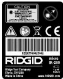
CAUTION RIGID Hedge Tool Company Elgita, OH USA Made in China SZSR7500021042 micro IR-200 1 x 1/4 Battery www.ridgid.comSet-Up and Operation
WARNING


Do not look into the laser beam. Looking into the laser beam may be hazardous to the eyes. Do not look at the laser beam with optical aids (such as binoculars or telescopes).
Do not direct the laser beam towards other people. Make sure the laser is aimed above or below eye level. Laser beams may be hazardous to the eyes.
Take appropriate precautions when working near electrical, moving or hot parts. Close contact may cause electrical shock, entanglement, burns and other serious injury. Protective equipment may be required.
Set up and operate the infrared thermometer according to these procedures to reduce the risk of injury or incorrect measurements.
Set-Up
- Check for an appropriate work area as indicated in the General Safety Section.
- Inspect the object being measured to and confirm that you have correct equipment for the application. See the Specifications section for range, accuracy and other information.
There are a variety of factors that can affect the accuracy of the micro IR-200, including:
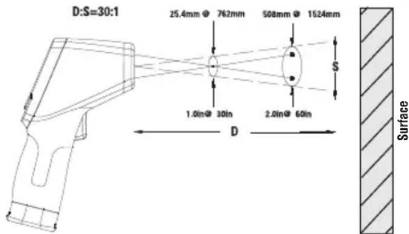
Field of view – The micro IR-200 uses two lasers to project points on either side of the area to be measured. These points indicate the approximate diameter of the area (the "Spot") that the temperature is being measured in. As the micro IR-200 moves further (D) away from the surface, that area and spot size (S) increases. The area is approximately ^30 times the distance to the surface. (See Figure 7.)
text_image
D:S=30:1 25.4mm 762mm 508mm 1524mm S 1.0in@ 30in 2.0in@ 60in D SurfaceFigure 7 – Field Of View
The spot should always be smaller than the surface. The smaller the surface, the closer the micro IR-200 should be to the surface. For the best accuracy, the surface should be twice as large as the spot.
Emissivity – Emissivity is a term use to describe energy emitting characteristics of materials and has a value ranging from 0 to 1. The micro IR-200 allows adjustment of the emissivity value from 0.10 to 1.00 to calculate temperatures. If the emissive property of a surface is unknown, an emissivity of 0.95 can be appropriate for many applications, such as painted surfaces. Values of emissivity for common materials are included in Figure 8.
| Material Emissivity | Material Emissivity | ||
| Aluminum, polished 0.05 | Paint 0.95 | ||
| Asphalt 0.88 | Paper, white | 0.90 | |
| Brick 0.90 | Plaster, rough | 0.89 | |
| Concrete, rough 0.91 | Rubber | 0.93 | |
| Copper, polished | 0.04 | Steel, galvanized | 0.28 |
| Glass | 0.95 | Steel, oxidized | 0.88 |
| Limestone | 0.92 | Water | 0.96 |
| Marble, polished | 0.90 | ||
Figure 8 – Emissivity Values of Common Materials
Temperature – While the micro IR-200 compensates for variation from ambient temperature, large changes in ambient and measured temperatures can reduce accuracy. When significant changes in ambient temperature (more than 30^ F or 17^ C) are encountered, allow fifteen minutes for the micro IR-200 to adjust for best accuracy.
Obstructions – Steam, dust, smoke and other obstructions like glass or plastic between the micro IR-200 and the surface being measured can decrease accuracy. These obstruct the unit optics or give false readings (measure the temperature of the glass instead of the surface). Do not use when obstructions are present.
- Make sure that all equipment has been properly inspected.
Operation
Turning ON and OFF (Taking Measurements)
- Hold the micro IR-200 by the handle grip and point it at the surface to be measured. Keep away from any electrical, moving or hot parts. Make sure that the unit is pointed in a safe direction away from any bystanders before turning ON.
- Squeeze the trigger to turn the micro IR-200 ON. When the trigger is squeezed, the SCAN icon will be ON, and the micro IR-200 will continuously update the displayed current temperature value and display the maximum temperature value since the unit was turned ON.
The micro IR-200 can be moved slowly over the surface to locate hot or cool areas. See the High Alarm and Low Alarm sections for information on high and low alarm settings.
- When the trigger is released, the HOLD icon will be ON. The micro IR-200 will automatically turn OFF after seven seconds unless the unit is in Continuous Measurement mode.
micro IR-200 Controls
text_image
RIDGID LCD Display 317 317 micro R-200 Trigger Laser Down Button/ Backlight Menu ButtonFigure 8 – micro IR-200 Display/Buttons
Continuous Measurement (Scanning) Mode
The micro IR-200 can be locked ON to allow measurements without holding the trigger. Make sure that the unit is pointed in a safe direction away from any bystanders before turning ON. Turn the micro IR-200 ON by squeezing and holding the trigger. While holding the trigger, press and release the menu button. The SCAN and Lock icons will be ON. Release the trigger, and the micro IR-200 will continuously update the measured temperature until the trigger switch is squeezed and released again.
Laser Enabled/Disabled
If needed, the lasers used for aiming can be turned off to help conserve battery life. If this is done, extra care must be used when aim-
ing the micro IR-200 to ensure good readings. To enable or disable, while squeezing the trigger, press and release the laser enable button. The Laser Enable icon will be ON when the laser is enabled.
Backlight
If using in a low lit area, the micro IR-200 is equipped with a display backlight. To turn the backlight ON and OFF, with the unit ON, press the backlight button.
Menu Button Use
After squeezing the trigger, pressing and releasing the menu button will allow you to cycle through the following settings in this order: High Alarm ON/OFF, High Alarm Temperature Setting, Low Alarm ON/OFF, Low Alarm Temperature Setting, Temperature Display Units, Emissivity.
High Alarm
High Alarm will give an audible tone when the current temperature exceeds a preset limit. To turn the High Alarm ON, squeeze and release the trigger, and then press and release the menu button until the High Alarm icon is flashing. Use the up/down buttons to turn the High Alarm feature ON/OFF as indicated on the current temperature value line. Press and release the menu button again. The High Alarm icon will continue to flash, and the High Alarm temperature will appear. Use the up/down buttons to change the High Alarm temperature as desired. Squeeze the trigger to exit the Settings mode and save your selection.
Low Alarm
Low Alarm will give an audible tone when the current temperature falls below a preset limit. To turn the Low Alarm ON, squeeze and release the trigger, and then press and release the menu button until the Low Alarm icon is flashing. Use the up/down buttons to turn the Low Alarm feature ON/OFF as indicated on the current temperature value line. Press and release the menu button again. The Low Alarm icon will continue to flash, and the Low Alarm temperature will appear. Use the up/down buttons to change the Low Alarm temperature as desired. Squeeze the trigger to exit the Settings mode and save your selection.
Temperature Display Units - °C/°F
The micro IR-200 can display temperatures in either degrees Celsius (C) or Fahrenheit (F). To change the display unit, squeeze and release the trigger, and then press and release the menu button until the temperature unit on the screen is flashing. Use the up/down buttons to switch between F or C as desired. Squeeze the trigger to exit the Settings mode and save your selection.
Emissivity
The emissivity value can be set from 0.10 to 1.00. See the Set-Up section to determine an appropriate value for your application. To adjust this value, squeeze and release the trigger, and then press and release the menu button until the emissivity value on the screen is flashing. Use the up/down buttons to increase or decrease the emissivity value. Squeeze the trigger to exit the Settings mode and save your selection.
Cleaning
-Do not immerse the RIDGID micro IR-200 Non-Contact Infrared Thermometer in water. Wipe off dirt with a damp soft cloth. Do not use aggressive cleaning agents or solutions. Treat the instrument as you would a telescope or camera.
Storage
^a The RIDGID micro IR-200 Infrared Thermometer must be stored in a dry secure area between -10^ ( 14^ ) and 60^ ( 140^ ).
Store the tool in a locked area out of the reach of children and people unfamiliar with the micro IR-200.

micro IR-200 Non-Contact Infrared Thermometer
Remove the battery before any long period of storage or shipping to avoid battery leakage.
Service and Repair
WARNING
Improper service or repair can make the RIDGID micro IR-200 Non-Contact Infrared Thermometer unsafe to operate.
Service and repair of the micro IR-200 must be performed by a RIDGID Authorized Independent Service Center.
For information on your nearest RIDGID Authorized Independent Service Center or any service or repair questions:
- Contact your local RIDGID distributor.
- Visit RIDGID.com to find your local RIDGID contact point.
- Contact Ridge Tool Technical Service Department at rtctechservices@emerson.com, or in the U.S. and Canada call (800) 519-3456.
Disposal
Parts of the RIDGID micro IR-200 Non-Contact Infrared Thermo-meter contain valuable materials and can be recycled. There are companies that specialize in recycling that may be found locally. Dispose of the components in compliance with all applicable regulations. Contact your local waste management authority for more information.
For EC Countries: Do not dispose of elec trical equipment with household waste!
According to the European Guideline 2012/19/EU for Waste Electrical and Electronic Equipment and its implementation into national legislation, electrical equipment
that is no longer usable must be collected separately and disposed of in an environmentally correct manner.
Battery Disposal
For EC countries: Defective or used batteries must be recycled according to the guideline 2012/19/EU.
micro IR-200
CONSERVEZ CES INSTRUCTIONS!
Sécurité des lieux
natural_image
RIOGIO digital thermometer and its case with a small rectangular device (no visible text or symbols on the device body)natural_image
Close-up of hands holding a black handheld device with a small connector (no visible text or symbols)natural_image
Close-up of a hand inserting a black plastic component into a cylindrical device (no visible text or symbols)natural_image
Close-up of a black RIDGID handheld device (no visible text or symbols on body)
text_image
CAUTION LARGE INSURANCE COVID-19:00 COVID-19:00 COVID-19:00 COVID-19:00 COVID-19:00 COVID-19:00 COVID-19:00 COVID-19:00 COVID-19:00 COVID-19:00 COVID-19:00 COVID-19:00 COVID-19:00 COVID-20 COVID-20 COVID-20 COVID-20 COVID-20 COVID-20 COVID-20 COVID-20 COVID-20 COVID-20 COVID-20 COVID-20 COVID-20 COVID-20 COVID-20 COVID-20 COVID-20 COVID-20 COVID-20 COVID-20 COVID-19:00 COVID-19:00 COVID-19:00 COVID-19:00 COVID-19:00 COVID-19:00 COVID-19:00 COVID-19:00 COVID-19:00 COVID-19:00 COVID-19:00 COVID-19:00 COVID 19:00 COVID 19:00 COVID 19:00 COVID 19:00 COVID 19:00 COVID 19:00 COVID 19:00 COVID 19:00 COVID 19:00 COVID 19:00 COVID 19:00 COVID 19:00 COVID 19:35 COVID 19:35 COVID 19:35 COVID 19:35 COVID 19:35 COVID 19:35 COVID 19:35 COVID 19:35 COVID 19:35 COVID 19:35 COVID 19:35 COVID 19:35 COVID 19:35 COVID 26/7/3/3/3/3/3/3/3/3/3/3/3/3/3/3/3/3/3/3/3/3/3/3/3/3/3/3/3/3/3/3/3/3/3/3/3/3/3/3/3/3/3/3/3/3/3/3/3/3/3/3/4text_image
D:S=30:1 25.4mm @ 762mm 508mm @ 1624mm S 1.0in@ 30in 2.0in@ 60in D Surface Figure 7 – Champ de visiontext_image
RIDGID RIDGID 317° -317° +0.00 MOSO SR-205
ADVERTENCIA
natural_image
RiGIO digital thermometer and its case with a small electronic device (no visible text or symbols on the device body)natural_image
Close-up of hands holding a black and white device with a connector, no visible text or symbolsnatural_image
Close-up of a hand inserting a black plastic component into a cylindrical device (no visible text or symbols)natural_image
Close-up of a black RIDGID handheld device with no visible text or symbols on its body
text_image
CAUTION LARGE PATTERN SPEE 1000000000000000000000000000000000000000000000000000000000000000000000 Ridg ID: 753456789 Ridg ID: 753456789 Ridg ID: 753456789 Ridg ID: 753456789 Ridg ID: 753456789 Ridg ID: 753456789 Ridg ID: 753456789 Ridgs Tool Company Elvria, ON USA Made in China micro IR-200 1x W Battery www.RIDGID.comtext_image
D:S=30:1 25,4mm @ 762 mm 508mm @ 1524 mm 1,0 plugs. @ 30 plugs. 2,0 plugs. @ 60 plugs. D SuperficieFigura 7 – Campo visual
natural_image
RiGID handheld device with digital display and a black case containing a branded bag (no visible text or symbols on main subject)Abbildung 1 - micro IR-200 Kontaktloses Infrarotthermometer
natural_image
Close-up of hands holding a black electronic device with a circular connector (no visible text or symbols)natural_image
Close-up of a hand inserting a black plastic device into a cylindrical housing (no visible text or symbols)natural_image
Close-up of a black RIDGID device with no visible text or symbols on its bodytext_image
D:S=30:1 25.4mm @ 762mm 504mm @ 1524mm 1.0in@ 30in 2.0in@ 60in S D Oberflächenatural_image
RiGID medical imaging device with a black case and a small rectangular component (no visible text or symbols)Figuur 1 - micro IR-200 Contactloze infraroodthermometer
Onderdelen LCD-displaypictogrammen
natural_image
Close-up of hands holding a black Sony 3D camera module with a central connector (no visible text or symbols)natural_image
Close-up of a hand inserting a black plastic component into a device (no visible text or symbols)natural_image
Close-up of a black RIDGID handheld device with no visible text or symbols on its bodytext_image
D:S=30:1 25.4mm @ 762mm 508mm @ 1524mm 1.0in@ 30in 2.0in@ 60in S D Oppervlaknatural_image
RiGID medical imaging device with a black case and a small rectangular component (no visible text or symbols)natural_image
Close-up of hands holding a black electronic device with a connector, no visible text or symbolsnatural_image
Close-up of a hand inserting a black plastic component into a black cylindrical device (no visible text or symbols)natural_image
Black RIDGID device with warning label (no readable text or symbols beyond branding)
text_image
CAUTION RED GENDER COVID COVID-19 COVID COVID-19 COVID COVID-19 COVID COVID-19 COVID COVID-19 COVID COVID-19 COVID COVID-19 COVID COVID-19 COVID COVID-19 COVID COVID-19 COVID COVID-19 COVID COVID-19 COVID COVID-19 COVID COVID-19 COVID COVID-19 COVID COVID-19 COVID COVID-19 COVID COVID- RIDGID. Ridge Tool Company Elvita, DR USA Made in China micro IR-200 5.0 gm 400 gm www.RIDGID.comtext_image
D:S=30:1 25.4mm @ 762mm 508mm @ 1524mm 1,0in@ 30in 2,0in@ 60in D Superfine68^ 1472^ ( 20^ 800^ )
±0,5% ou ±0.9°F (0,5°C)
Tempo de resposta.... 150 ms
natural_image
RiGID handheld device with a black case and a small rectangular component nearby (no visible text or symbols)Figura 1 – Termómetro de Infravermelhos Portátil micro IR-200
natural_image
Close-up of hands holding a black handheld device with a circular connector (no visible text or symbols)natural_image
Close-up of a hand inserting a black plastic device into a black housing (no visible text or symbols)natural_image
Black and white photo of a RIDGID handheld device (no visible text or symbols on body)Figura 6 – Rótulos de aviso

text_image
CAUTION COVID-19 COVID-19 COVID-19 COVID-19 COVID-19 COVID-19 COVID-19 COVID-19 COVID-19 COVID-19 COVID-19 COVID-19 COVID-19 COVID-19 COVID-19 COVID-19 COVID-19 COVID-19 COVID-19 COVID-19 COVID-10 COVID-10 COVID-10 COVID-10 COVID-10 COVID-10 COVID-10 COVID-10 COVID-10 COVID-10 COVID-10 COVID-10 COVID-10 COVID-10 COVID-10 COVID-10 COVID-10 COVID-10 COVID-10 COVID-10 COVID-15 COVID-15 COVID-15 COVID-15 COVID-15 COVID-15 COVID-15 COVID-15 COVID-15 COVID-15 COVID-15 COVID-15 COVID-15 COVID-15 COVID-15 COVID-15 COVID-15 COVID-15 COVID-15 COVID-15 COVID-10 COVID-10 COVID-10 COVID-10 COVID-10 COVID-10 COVID-10 COVID-10 COVID-10 COVID-10 COVID-10 COVID-10 COVID-10 COVID-10 COVID-10 COVID-10 COVID-10 COVID-10 COVID-10 COVID-12 COVID-12 COVID-12 COVID-12 COVID-12 COVID-12 COVID-12 COVID-12 COVID-12 COVID-12 COVID-12 COVID-12 COVID-12 COVID-12 COVID-12 COVID-12 COVID-12 COVID-12 COVID-12 COVID-12 COVID-13 COVID-13 COVID-13 COVID-13 COVID-13 COVID-13 COVID-13 COVID-13 COVID-13 COVID-13 COVID-13 COVID-13 COVID-13 COVID-13 COVID-13 COVID-13 COVID-13 COVID-13 COVID-13 COVID-13 COVID-14 COVID-14 COVID-14 COVID-14 COVID-14 COVID-14 COVID-14 COVID-14 COVID-14 COVID-14 COVID-14 COVID-14 COVID-14 COVID-14 COVID-14 COVID-14 COVID-14 COVID-14text_image
D:S=30:1 25.4mm @ 762mm 508mm @ 1524mm 1.0in@ 30in 2.0in@ 60in D SuperficialFCC-information....104
Elektromagnetisk kompatibilitet (EMC)....104
Byta/Installera batterier 104
natural_image
RiGIO medical imaging device with a black case and a digital thermometer, no visible text or symbols on the main components.Figure 1 – micro IR-200 Kontaktfri infraröd termometer
Delar Ikoner på LCD-displayen
text_image
RIDGID LCD-display 3.17 3.0 Ned-knapp/ Belysning Upp-knapp/ Laser aktiv Avtryckare Handtag Menyknapp BatteriutrymmeFigur 2 – Knappar på micro IR-200
text_image
Infraröd sensor RhGID Laser Laser Avtryckare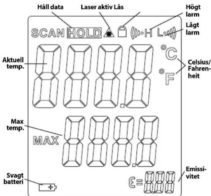
text_image
Håll data Laser aktiv Lås SCAN HOLD Aktuell temp. Max temp. Svagt batteri Högt larm Lågt larm Celsius/Fahrenheit MAX Emissivitetnatural_image
Close-up of hands holding a black electronic device with a connector, showing internal components (no visible text or symbols)Figur 4 – Öppna batteriutrymmet
Byta/Installera batterier
natural_image
Close-up of a hand inserting a black plastic component into a cylindrical device (no visible text or symbols)natural_image
Close-up of a black RIDGID device with no visible text or symbols on its bodyFigur 6 – Varningsdekaler

text_image
CALIFORN MINI METER MINI METER MINI METER MINI METER MINI METER MINI METER MINI METER MINI METER MINI METER MINI METER MINI METER MINI METER MINI METER MINI METER MINI METER MINI METER MINI METER MINI METER MINI METER MINI METER MINI MISTER MINI MISTER MINI MISTER MINI MISTER MINI MISTER MINI MISTER MINI MISTER MINI MISTER MINI MISTER MINI MISTER MINI MISTER MINI MISTER MINI MISTER MINI MISTER MINI MISTER MINI MISTER MINI MISTER MINI MISTER MINI MISTER MINI MISTER MINI MISTEMA MINI MISTEMA MINI MISTEMA MINI MISTEMA MINI MISTEMA MINI MISTEMA MINI MISTEMA MINI MISTEMA MINI MISTEMA MINI MISTEMA MINI MISTEMA MINI MISTEMA MINI MISTEMA MINI MISTEMA MINI MISTEMA MINI MISTEMA MINI MISTEMA MINI MINER MINI MINER MINI MINER MINI MINER MINI MINER MINI MINER MINI MINER MINI MINER MINI MINER MINI MINER MINI MINER MINI MINER MINI MINER MINI MINER MINI MINER MINI MINER MINI MINER MINI MINER MINI MINER MINI MINER MINI MINR MINI MINR MINI MINR MINI MINR MINI MINR MINI MINR MINI MINR MINI MINR MINI MINR MINI MINR MINI MINR MINI MINR MINI MINR MINI MINR MINI MINR MINI MINR MINI MINR MINI MINR MINI MINR MINI MINR MINI MINMIR MINI MINMIR MINI MINMIR MINI MINMIR MINI MINMIR MINI MINMIR MINI MINMIR MINI MINMIR MINI MINMIR MINI MINMIR MINI MINMIR MINI MINMIR MINI MINMIR MINI MINMIR MINI MINMIR MINI MINMIR MINI MINMIR MINI PINER 2.5 MB 1.5 MB 0.5 MBtext_image
D:S=30:1 25.4mm @ 762mm 508mm @ 1524mm 1.0in@ 30in 2.0in@ 60in S D YtaFigur 7 – Synfält
Repeterbarhed....-58°F \~ 68°F (50°C \~20°C):
±2.3°F (1,3°C)
68^ 1472^ ( 20^ 800^ )
±0,5% eller ±0,9°F (0,5°C)
Svartid.... 150 ms
Spektralrespons.... 8\~14 um
Emissivitet...... Justerbar, 0,10 – 1,00
natural_image
RiGID medical imaging device with a black bandage and a digital thermometer, accompanied by a small rectangular component (no visible text or symbols on the device itself)Figur 1 – micro IR-200 infrarødt termometer
Dele LCD-display-ikoner
natural_image
Close-up of hands holding a black electronic device with a connector, showing internal components (no visible text or symbols)Figur 4 – Sådan fjernes batterirummet
natural_image
Close-up of a hand inserting a black plastic component into a black cylindrical device (no visible text or symbols)natural_image
Close-up of a black RIDGID device with visible branding and a triangular warning symbol (no readable text beyond logo)text_image
CAUTION RED GENDER MINI-100 MINI-100 MINI-100 MINI-100 MINI-100 MINI-100 MINI-100 MINI-100 MINI-100 MINI-100 MINI-100 MINI-100 MINI-100 MINI-100 MINI-100 S2Q7509321602 RIDGID. Ridge Tool Company Elvria, OH USA Made in China micro IR-200 1 x 1 84mm www.RIDGID.comOpsætning og drift
ADVARSEL


text_image
D:S=30:1 25.4mm @ 762mm 508mm @ 1524mm 1.0in@ 30in 2.0in@ 60in S D OverfladeFigur 7 – Synsfelt
natural_image
RiDGID medical scanner with a black case and a small rectangular device beside it (no visible text or symbols on the device itself)natural_image
Close-up of hands holding a black electronic device with a connector (no visible text or symbols)natural_image
Close-up of a hand inserting a black plastic component into a device (no visible text or symbols)natural_image
Close-up of a black RIDGID device with no visible text or symbols on its bodyFigur 6 – Varselmerker
text_image
CAUTION LEMONDAY 2018 COVID-19:00 COVID-19:00 COVID-19:00 COVID-19:00 COVID-19:00 COVID-19:00 COVID-19:00 COVID-19:00 COVID-19:00 COVID-19:00 COVID-19:00 COVID-19:00 COVID-19:00 COVID-20 COVID-20 COVID-20 COVID-20 COVID-20 COVID-20 COVID-20 COVID-20 COVID-20 COVID-20 COVID-20 COVID-20 COVID-20 COVID-20 COVID-20 COVID-20 COVID-20 COVID-20 COVID-20 COVID-20 COVID-19 COVID-19 COVID-19 COVID-19 COVID-19 COVID-19 COVID-19 COVID-19 COVID-19 COVID-19 COVID-19 COVID-19 COVID-19 COVID-19 COVID-19 COVID-19 COVID-19 COVID-19 COVID-19 COVID-19 COVID-18 COVID-18 COVID-18 COVID-18 COVID-18 COVID-18 COVID-18 COVID-18 COVID-18 COVID-18 COVID-18 COVID-18 COVID-18 COVID-18 COVID-18 COVID-18 COVID-18 COVID-18 COVID-18 COVID-18 COVID-17 COVID-17 COVID-17 COVID-17 COVID-17 COVID-17 COVID-17 COVID-17 COVID-17 COVID-17 COVID-17 COVID-17 COVID-17 COVID-17 COVID-17 COVID-17 COVID-17 COVID-17 COVID-17 COVID-17 COVID-16 COVID-16 COVID-16 COVID-16 COVID-16 COVID-16 COVID-16 COVID-16 COVID-16 COVID-16 COVID-16 COVID-16 COVID-16 COVID-16 COVID-16 COVID-16 COVID-16 COVID-16 COVID-16 COVID-16 COVID-15 COVID-15 COVID-15 COVID-15 COVID-15 COVID-15 COVID-15 COVID-15 COVID-15 COVID-15 COVID-15 COVID-15 COVID-15 COVID-15 COVID-15 COVID-15 COVID-15 COVID-15 COVID-15 COVID-15 COVID-14 COVID-14 COVID-14 COVID-14 COVID-14 COVID-14 COVID-14 COVID-14 COVID-14 COVID-14 COVID-14 COVID-14 COVID-14 COVID-14 COVID-14 COVID-14 COVID-14Klargjøring og bruk
ADVARSEL


Ikke se rett mot laserstrålen. Det kan være farlig for øynene å se rett mot laserstrålen. Ikke se rett mot laserstrålen med optiske hjel pemidler (som kikkerter eller teleskoper).
text_image
D:S=30:1 25.4mm @ 762mm 504mm @ 1524mm 1.0in@ 30in 2.0in@ 60in S D OverflateFigur 7 - Synsfelt
natural_image
RiG3D medical imaging device with a black case and a small rectangular component (no visible text or symbols)natural_image
Close-up of hands holding a black electronic device with a small circular connector (no visible text or symbols)natural_image
Close-up of a hand inserting a black plastic component into a black cylindrical device (no visible text or symbols)natural_image
Close-up of a black RIDGID device with a triangular warning symbol on the side (no readable text or symbols beyond branding)text_image
D:S=30:1 25.4mm @ 762mm 508mm @ 1524mm 1.0in@ 30in 2.0in@ 60in S D Pintanatural_image
RiGID medical imaging device with a black case and a digital thermometer, no visible text or symbols on the main components.natural_image
Close-up of hands holding a black electronic device with a connector, no visible text or symbolsnatural_image
Close-up of a hand inserting a black plastic component into a device (no visible text or symbols)natural_image
Close-up of a black RIDGID handheld device with no visible text or symbols on its bodytext_image
D:S=30:1 25.4mm @ 762mm 508mm @ 1524mm 1,0in@ 30in 2,0in@ 60in S D Powierzchnianatural_image
RiGID handheld device with a black case and a small rectangular component nearby (no visible text or symbols)natural_image
Close-up of hands holding a black handheld device with a circular connector (no visible text or symbols)natural_image
Close-up of a hand inserting a black plastic component into a black electrical plug (no visible text or symbols)natural_image
Close-up of a black RIDGID device with no visible text or symbols on its bodytext_image
CALIFORN RIDGE TECOLOGY COMPANY Ethyria, OR USA Made in China 52067590021802 RIDGID. micro IR-200 1 x 10 System www.RIDGID.comNastavení a provoz
VÝSTRAHA


text_image
D:S=30:1 25.4mm @ 762mm 508mm @ 1524mm 1.0in@ 30in 2.0in@ 60in S D Povrchtext_image
RIDGID 3.17°C - 3.17°C micro 18-20M
VÝSTRAHA
TIETO POKYNY USCHOVAJTE!
TIETO POKYNY USCHOVAJTE!
natural_image
RiGID medical imaging device with a black case and a small rectangular component (no visible text or symbols)natural_image
Close-up of hands holding a black electronic device with a connector (no visible text or symbols)natural_image
Close-up of a hand inserting a black plastic component into a black cylindrical device (no visible text or symbols)natural_image
Close-up of a black RIDGID handheld device with no visible text or symbols on its bodytext_image
D:S=30:1 25.4mm @ 762mm 508mm @ 1524mm 1.0in@ 30in 2.0in@ 60in S D Povrchnatural_image
RiGID medical imaging device with a black case and a small rectangular component (no visible text or symbols)natural_image
Close-up of hands holding a device with a connector, showing internal components (no visible text or symbols)natural_image
Close-up of a hand inserting a black plastic component into a device (no visible text or symbols)natural_image
Black RIDGID device with triangular warning symbol (no readable text or symbols beyond branding)Figura 6 – Etichete de avertizare

text_image
CALITON RED SIGNATURE MINI MOUNTED BEANS SPEED CHILLER TOMATO CAULIFLOWER COALICUMBER COVID-19 COVID-19 COVID-19 COVID-19 COVID-19 COVID-19 COVID-19 COVID-19 COVID-19 COVID-19 COVID-19 COVID-19 COVID-19 COVID-19 COVID-19 COVID-19 COVID-19 COVID-19 COVID-19 COVID-19 COVID-10 COVID-10 COVID-10 COVID-10 COVID-10 COVID-10 COVID-10 COVID-10 COVID-10 COVID-10 COVID-10 COVID-10 COVID-10 COVID-10 COVID-10 COVID-10 COVID-10 COVID-10 COVID-10 COVID-10 COVID-15 COVID-15 COVID-15 COVID-15 COVID-15 COVID-15 COVID-15 COVID-15 COVID-15 COVID-15 COVID-15 COVID-15 COVID-15 COVID-15 COVID-15 COVID-15 COVID-15 COVID-15 COVID-15 COVID-15 COVID-10 COVID-10 COVID-10 COVID-10 COVID-10 COVID-10 COVID-10 COVID-10 COVID-10 COVID-10 COVID-10 COVID-10 COVID-10 COVID-10 COVID-10 COVID-10 COVID-10 COVID-10 COVID-10 COVID-12 COVID-12 COVID-12 COVID-12 COVID-12 COVID-12 COVID-12 COVID-12 COVID-12 COVID-12 COVID-12 COVID-12 COVID-12 COVID-12 COVID-12 COVID-12 COVID-12 COVID-12 COVID-12 COVID-12 COVID-13 COVID-13 COVID-13 COVID-13 COVID-13 COVID-13 COVID-13 COVID-13 COVID-13 COVID-13 COVID-13 COVID-13 COVID-13 COVID-13 COVID-13 COVID-13 COVID-13 COVID-13 COVID-13 COVID-13 COVID-14 COVID-14 COVID-14 COVID-14 COVID-14 COVID-14 COVID-14 COVID-14 COVID-14 COVID-14 COVID-14 COVID-14 COVID-14 COVID-14 COVID-14text_image
D:S=30:1 25.4mm @ 762mm 508mm @ 1524mm 1.0in@ 30in 2.0in@ 60in D SuprafațăFigura 7 – Câmpul vizual
natural_image
Product photo of a Rogio RODG sensor device with a black case and a small rectangular component (no visible text or symbols)natural_image
Close-up of hands holding a black electronic device with a connector, no visible text or symbolsnatural_image
Close-up of a hand inserting a black plastic component into a cylindrical device (no visible text or symbols)natural_image
Close-up of a black RIDGID device with no visible text or symbols on its bodytext_image
D:S=30:1 25.4mm @ 762mm 508mm @ 1524mm 1.0in@ 30in 2.0in@ 60in S D Felületnatural_image
RiGID handheld device with a black case and a small rectangular component nearby (no visible text or symbols on the device itself)natural_image
Close-up of hands holding a black electronic device with a connector, no visible text or symbolsnatural_image
Close-up of a hand inserting a black plastic component into a black cylindrical device (no visible text or symbols)natural_image
Close-up of a black RIDGID handheld device with no visible text or symbols on the body
text_image
CAUTION COVID-1980 COVID-1981 COVID-1982 COVID-1983 COVID-1984 COVID-1985 COVID-1986 COVID-1987 COVID-1988 COVID-1989 COVID-1990 COVID-1991 COVID-1992 COVID-1993 COVID-1994 COVID-1995 COVID-1996 COVID-1997 COVID-1998 COVID-1999 COVID-2000 COVID-2001 COVID-2002 COVID-2003 COVID-2004 COVID-2005 COVID-2006 COVID-2007 COVID-2008 COVID-2009 COVID-2010 COVID-2011 COVID-2012 COVID-2013 COVID-2014 COVID-2015 COVID-2016 COVID-2017 COVID-2018 COVID-2019 COVID-2020 COVID-2021 COVID-2022 COVID-2023 COVID-2024 COVID-2025 COVID-2026 COVID-2027 COVID-2028 COVID-2029 COVID-2030 COVID-2031 COVID-2032 COVID-2033 COVID-2034 COVID-2035 COVID-2036 COVID-2037 COVID-2038 COVID-2039 COVID-2040 COVID-2041 COVID-2042 COVID-2043 COVID-2044 COVID-2045 COVID-2046 COVID-2047 COVID-2048 COVID-2049 COVID-2050 COVID-2051 COVID-2052 COVID-2053 COVID-2054 COVID-2055 COVID-2056 COVID-2057 COVID-2058 COVID-2059 COVID-2060 COVID-2061 COVID-2062 COVID-2063 COVID-2064 COVID-2065 COVID-2066 COVID-2067 COVID-2068 COVID-2069 COVID-2070 COVID-2071 COVID-2072 COVID-2073 COVID-2074 COVID-2075 COVID-2076 COVID-2077 COVID-2078 COVID-2079 COVID-2080 COVID-2081 COVID-2082 COVID-2083 COVID-2084 COVID-2085 COVID-2086 COVID-2087 COVID-2088 COVID-2089 COVID-2090 COVID-2091 COVID-2092 COVID-2093 COVID-2094 COVID-2095 COVID-2096 COVID-2097 COVID-2098 COVID-2099 COVID-2100text_image
D:S=30:1 25.4mm @ 762mm 508mm @ 1524mm 1.0in@ 30in 2.0in@ 60in S D EmpaiveaIzjava FCC (Federal Comunication Commission)....244
Elektromagnetska sukladnost (EMC)......244
Izmjena/Ugrađivanje baterija....244
natural_image
RiGID medical imaging device with a black case and a small rectangular component (no visible text or symbols)Slika 1 – mikro IR-200 beskontaktni infracrveni termometar
Dijelovi Ikone LCD-displeja
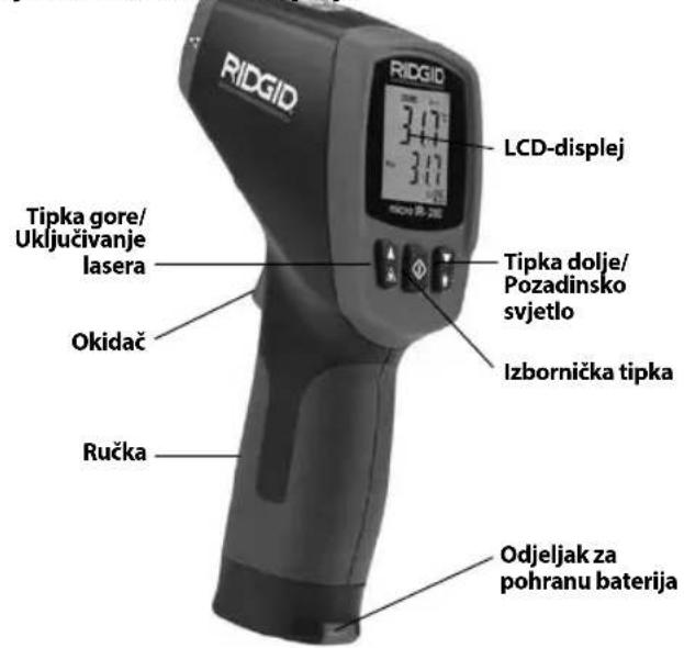
text_image
RIDGID LCD-displej Tipka gore/ Uključivanje lasera Okidač Ručka Tipka dolje/ Pozadinsko svjetlo Izbornička tipka Odjeljak za pohranu baterijaIzjava FCC (Federal Comunication Commission)
Ova oprema je bila iskušana i za nju je utvrđeno da odgovara granicama za Klasu B digitalnih uređaja, te slijedi dio 15 od FCC pravila. Ta ograničenja namijenjena su za osiguranje razumne razine zaštite protiv štetnih smetnji u kućanstvima.
Ova oprema stvara, koristi i može emitirati energiju radijske frekvencije te, ako nije ugrađena i korištena u skladu s uputama, može izazvati štetne smetnje u radijskim komunikacijama.
natural_image
Close-up of hands holding a black electronic device with a connector, no visible text or symbolsSlika 4 – Uklanjanje poklopca odjeljka za baterije
natural_image
Close-up of a hand inserting a black plastic device into a cylindrical housing (no visible text or symbols)Slika 5 – Nosač baterije i oznaka polariteta
natural_image
Black RIDGID device with visible branding and control buttons (no readable text beyond brand name)
text_image
CAUTION RED GID Hedge Tool Company Gyra, OR USA Media in China 82067999321882 MICRO IR-200 5.0 % 40%text_image
D:S=30:1 25.4mm @ 762mm 508mm @ 1524mm 1.0in@ 30in 2.0in@ 60in S D PovršinaSlika 7 – Vidokrug
natural_image
RiGID handheld device with digital display and black case, no visible text or symbols on main subjectnatural_image
Close-up of hands holding a black electronic device with a connector, no visible text or symbolsnatural_image
Close-up of a hand inserting a black plastic component into a device (no visible text or symbols)natural_image
Close-up of a black RIDGID device with no visible text or symbols on its bodySlika 6 – Opozorilne nalepke
text_image
CAUTION HAPP MANNER SINEMA MATERIALS TOLERANCE CLOSURE SINEMA CAUTIONS COVID-19 COVID-20 COVID-21 COVID-22 COVID-23 COVID-24 COVID-25 COVID-26 COVID-27 COVID-28 COVID-29 COVID-30 COVID-31 COVID-32 COVID-33 COVID-34 COVID-35 COVID-36 COVID-37 COVID-38 COVID-39 COVID-40 COVID-41 COVID-42 COVID-43 COVID-44 COVID-45 COVID-46 COVID-47 COVID-48 COVID-49 COVID-50 COVID-51 COVID-52 COVID-53 COVID-54 COVID-55 COVID-56 COVID-57 COVID-58 COVID-59 COVID-60 COVID-61 COVID-62 COVID-63 COVID-64 COVID-65 COVID-66 COVID-67 COVID-68 COVID-69 COVID-70 COVID-71 COVID-72 COVID-73 COVID-74 COVID-75 COVID-76 COVID-77 COVID-78 COVID-79 COVID-80 COVID-81 COVID-82 COVID-83 COVID-84 COVID-85 COVID-86 COVID-87 COVID-88 COVID-89 COVID-90 COVID-91 COVID-92 COVID-93 COVID-94 COVID-95 COVID-96 COVID-97 COVID-98 COVID-99 COVID-100 RIDGID micro IR-200 Ridge Test Company 1: 100 GBm Eylea, OH USA Made in China www.RIDGID.comPriprava in uporaba
OPOZORILO


text_image
D:S=30:1 25.4mm Ø 762mm 508mm Ø 1524mm 1.0in Ø 30in 2.0in Ø 60in S D PovršinaSlika 7 – Vidno polje
natural_image
RiGID handheld device with digital display and a black case with a small rectangular component nearby (no visible text or symbols on main subject)Slika 1 – micro IR-200 beskontaktni infracrveni termometar
Delovi Ikone LCD-displeja
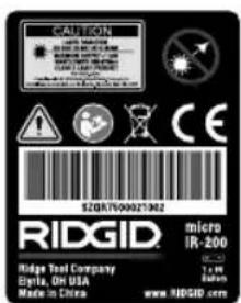
text_image
RIDGID LCD displej 317 317 Taster za naviše/ Aktiviranje lasera Okidač Rukohvat Taster za naniže/ Pozadinsko svetlo Taster Meni Odeljak za smeštaj baterijeSlika 2 – Delovi uređaja micro IR-200
text_image
Infracrveni senzor RIGDID Laser Laser Okidač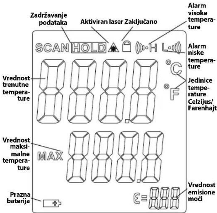
text_image
Zadržavanje podataka Aktiviran laser Zaključano SCAN HOLD Alarm visoke temperature Vrednost trenutne temperature Jedinice temperature Celzijus/Farenhajt Vrednost maksimalne temperature MAX Prazna baterija ε≡ Vrednost emisione moćiSlika 3 - micro IR-200 ikone displeja
Standardna oprema
- micro IR-200
-
Prenosna kutija
-
Baterija 1 x 9V
- Priručnik za rukovaoca
OBAVEŠTENJE Ova oprema se upotrebljava za merenje tem perature. Nepravilno korišćenje ili neodgovarajuća primena mogu do vesti do pogrešnog ili netačnog merenja. Izbor odgovarajuće metode merenja prema uslovima rada je dužnost korisnika.
Klasifikacija lasera

natural_image
Close-up of hands holding a device with a connector, showing internal components (no visible text or symbols)natural_image
Close-up of a hand inserting a black plastic device into a black cylindrical component (no visible text or symbols)Slika 5 – Držač baterije i oznaka polariteta
natural_image
Close-up of a black RIDGID device with no visible text or symbols on its bodytext_image
D:S=30:1 25.4mm Ø 762mm 508mm Ø 1524mm 1.0in Ø 30in 2.0in Ø 60in S D PovršinaSlika 7 – Vidno polje
natural_image
RiGID medical imaging device with a black case and a small rectangular component (no visible text or symbols)natural_image
Close-up of hands holding a black electronic device with a connector, no visible text or symbolsnatural_image
Close-up of a hand inserting a black plastic component into a black housing (no visible text or symbols)natural_image
Close-up of a black RIDGID handheld device with no visible text or symbols on its body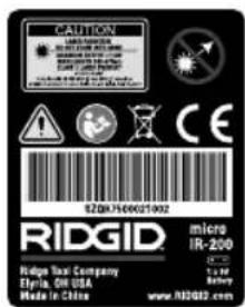
text_image
CAUTION REDUSTRY SINEMA MATERIALS HEDDING SINEMA SINEMA SINEMA SINEMA SINEMA SINEMA SINEMA SINEMA SINEMA SINEMA SINEMA SINEMA SINEMA SINEMA SINEMA SINEMA SINEMA SINEMA SINEMA SINEMA SINEMA SINEMA SINEMA SINEMA SINEMA SINEMA SINEMA SINEMA SINEMA SINEMA SINEMA SINEMA SINEMA SINEMA SINEMA SINEMA SINEMA SINEMA SINEMA SINEMA SINEMA SINEMA SINEMA SINEMA SINEMA SINEMM SINEMM SINEMM SINEMM SINEMM SINEMM SINEMM SINEMM SINEMM SINEMM SINEMM SINEMM SINEMM SINEMM SINEMM SINEMM SINEMM SINEMM SINEMM SINEMM SINEMN SINEMN SINEMN SINEMN SINEMN SINEMN SINEMN SINEMN SINEMN SINEMN SINEMN SINEMN SINEMN SINEMN SINEMN SINEMN SINEMN SINEMN SINEMN SINEMN SINEMM1000021902 SZQKJ7500021902 RIDGID. micro IR-200 Ridge Tax Company Eltria, Oil USA Made in Chinanatural_image
RiG3D medical imaging device with a black case and a digital thermometer, no visible text or symbols on the main components.natural_image
Close-up of hands holding a black electronic device with a connector, no visible text or symbolsnatural_image
Close-up of a hand inserting a black plastic component into a device (no visible text or symbols)natural_image
Close-up of a black RIDGID device with no visible text or symbols on its bodytext_image
D:S=30:1 25.4mm @ 762mm 508mm @ 1524mm 1.0in@ 30in 2.0in@ 60in S D Yizeynatural_image
RiGID medical scanner with a black case and a small rectangular device beside it (no visible text or symbols on the device itself)natural_image
Close-up of hands holding a black Bosch 3.0 smartphone with a small connector (no visible text or symbols)natural_image
Close-up of a hand inserting a black plastic component into a cylindrical device (no visible text or symbols)natural_image
Black RIDGID device with white branding and triangular warning symbol (no readable text or symbols beyond branding)text_image
D:S=30:1 25.4mm @ 762mm 508mm @ 1524mm 1.0in@ 30in 2.0in@ 60in S D Bet7-cypet - Køpy əpici
RIDGE TOOL COMPANY Ridge Tool Europe NV (RIDGID)
EC DECLARATION OF CONFORMITY
We declare that the machines listed above, when used in accordance with the operator's manual, meet the relevant requirements of the Directives and Standards listed below.
DÉCLARATION DE CONFORMITÉ CE
DEKLARACJA ZGODNOŚCI WE
Qualification: V.P. Engineering Date: 09/01/2020

For Warranty Information for your World Region visit RIDGID.com
Ridge Tool Europe NV (RIDGID)
Printed 11/20 999-995-066.09 EC45131 REV. E
©2015. 2020 RIDGID, Inc.
The Emerson logo and RIDGID logo are registered trademarks of Emerson Electric Co. or RIDGID, Inc. in the U.S. and other countries. All other trademarks belong to their respective holders.
RIDGID
EMERSON.