
Micro CM-100 - Measuring equipment RIDGID - Free user manual and instructions
Find the device manual for free Micro CM-100 RIDGID in PDF.

| Product Type | Digital Clamp Meter |
| Brand | RIDGID |
| Model | Micro CM-100 |
| Dimensions | 229 x 79 x 49 mm (9 x 3.1 x 1.9 in) |
| Weight | 303 g (0.67 lb) |
| Power Supply | 9V battery (NEDA 1604, IEC 6F22 or 6LR61) |
| Display | Backlit LCD > 1000 pixels |
| Clamp Opening | 30 mm (1.2 in) |
| Overvoltage Category | CAT III 600V, CAT II 1000V |
| Measurement Functions | DC/AC Voltage (600V max), DC/AC Current (1000A max), Resistance, Capacitance, Frequency, Temperature, Diode Test, Audible Continuity |
| DC/AC Current Ranges | 40A, 400A, 1000A |
| DC/AC Voltage Ranges | 400mV, 4V, 40V, 400V, 600V |
| DC Current Accuracy | ± 2.8% of reading + 10 digits (40A), ± 2.8% + 8 digits (400A), ± 3% + 8 digits (1000A) |
| DC Voltage Accuracy | ± 0.8% + 2 digits (400mV), ± 1.5% + 2 digits (4-400V), ± 2% + 2 digits (600V) |
| Special Functions | Peak Hold (P MAX/MIN), Data Hold (HOLD), DC Amps Zero Adjustment (DC ZERO), Backlight, Auto Power Off (20 min) |
| Safety | Double insulation, CE compliance, FCC Class B, Overvoltage protection |
| Operating Temperature | 0 °C to 50 °C (32 °F to 122 °F) |
| Storage Temperature | -30 °C to 60 °C (-22 °F to 140 °F), RH < 85% |
| Maintenance | Clean with damp soft cloth (do not immerse), alcohol swab for terminals |
| Included Accessories | Red/black test leads with caps, Type K adapter with temperature probe, manual, CD, carrying case |
| Repairability | Have repaired by a RIDGID authorized service center; use original parts |
| Warranty | Lifetime Warranty |
| Recycling | Do not dispose of with household waste; recycle according to EU directives (WEEE 2002/96/EC, batteries 2006/66/EC) |
Frequently Asked Questions - Micro CM-100 RIDGID
User questions about Micro CM-100 RIDGID
0 question about this device. Answer the ones you know or ask your own.
Ask a new question about this device
Download the instructions for your Measuring equipment in PDF format for free! Find your manual Micro CM-100 - RIDGID and take your electronic device back in hand. On this page are published all the documents necessary for the use of your device. Micro CM-100 by RIDGID.
USER MANUAL Micro CM-100 RIDGID
Recording Form for Machine Serial Number 1
Safety Symbols....2
General Safety Rules
Work Area Safety....2
Electrical Safety....2
Personal Safety....2
Equipment Use and Care 3
Service....3
Specific Safety Information
Digital Clamp Meter Safety 3
Description, Specifications and Standard Equipment
Description....4
Specifications 4
Standard Equipment....6
Controls 7
Icons....7
FCC Statement......8
Electromagnetic Compatibility (EMC) 8
Changing/Installing Batteries....8
Pre-Operation Inspection....9
Set-Up and Operation
Rotary Function Switch 10
Input Terminals....11
Pushbuttons ....11
DC/AC Voltage Measurement 12
DC/AC Current Measurement....12
Resistance Measurement 12
Diode Test 13
Continuity Check....13
Capacitance Measurement 13
Frequency Measurement 14
Temperature Measurement....14
Maintenance Instructions
Cleaning....15
Calibration....15
Accessories 15
Storage 15
Service and Repair 15
Disposal 16
Battery Disposal 16
Troubleshooting 16
Lifetime Warranty ......Back Cover
Original instructions
micro CM-100 Digital Clamp Meter
RIDGID®
| micro CM-100 Digital Clamp Meter | |
| Record Serial Number below and retain product serial number which is located on nameplate. | |
| Serial No. | |
Safety Symbols
In this operator's manual and on the product, safety symbols and signal words are used to communicate important safety information. This section is provided to improve understanding of these signal words and symbols.

This is the safety alert symbol. It is used to alert you to potential personal injury hazards. Obey all safety messages that follow this symbol to avoid possible injury or death.

DANGER
DANGER indicates a hazardous situation which, if not avoided, will result in death or serious injury.

WARNING
WARNING indicates a hazardous situation which, if not avoided, could result in death or serious injury.

CAUTION
CAUTION indicates a hazardous situation which, if not avoided, could result in minor or moderate injury.
NOTICE
NOTICE indicates information that relates to the protection of property.

This symbol means read the operator's manual carefully before using the equipment. The operator's manual contains important information on the safe and proper operation of the equipment.

This symbol indicates the risk of electrical shock.

This symbol indicates the presence of a high voltage hazard.
General Safety Rules
WARNING
Read all safety warnings and in struc tions. Failure to follow the warn ings and in-structions may result in electric shock, fire and/or serious injury.
SAVE THESE INSTRUCTIONS!
Work Area Safety
- Keep your work area clean and well lit. Cluttered or dark areas invite accidents.
- Do not operate equipment in explosive atmospheres, such as in the presence of flammable liquids, gases or dust. Equipment can create sparks which may ignite the dust or fumes.
- Keep children and by-standers away while operating equipment. Distractions can cause you to lose control.
Electrical Safety
- Avoid body contact with earthed or grounded surfaces such as pipes, radiators, ranges and refrigerators. There is an in creased risk of electrical shock if your body is earthed or grounded.
- Do not expose equipment to rain or wet conditions. Water entering equipment will increase the risk of electrical shock.
Personal Safety
- Stay alert, watch what you are doing and use common sense when operating equipment. Do not use equipment while you are tired or under the influence of drugs, alcohol or medication. A moment of inattention while operating equipment may result in serious personal injury.
- Use personal protective equipment. Always wear eye protection. Protective equipment such as as protective gloves and clothing, dust mask, non-skid safety shoes, hard hat, or hearing protection used for appropriate conditions will reduce personal injuries.
- Do not overreach. Keep proper footing and balance at all times. This enables better control of the equipment in unexpected situations.
Equipment Use and Care
- Do not force equipment. Use the correct equipment for your application. The correct equipment will do the job better and safer at the rate for which it is designed.
- Do not use equipment if the switch does not turn it ON and OFF. Any tool that cannot be controlled with the switch is dangerous and must be repaired.
- Store idle equipment out of the reach of children and do not allow persons unfamiliar with the equipment or these instructions to operate the equipment. Equipment can be dangerous in the hands of untrained users.
- Maintain equipment. Check for missing parts, breakage of parts and any other condition that may affect the equipment's operation. If damaged, have the equipment repaired before use. Many accidents are caused by poorly maintained equipment.
- Use the equipment and accessories in accordance with these instructions, taking into account the working conditions and the work to be performed. Use of the equipment for operations different from those intended could result in a hazardous situation.
- Use only accessories that are recommended by the manufacturer for your equipment. Accessories that may be suitable for one piece of equipment may become hazardous when used with other equipment.
- Keep handles dry and clean; free from oil and grease. Allows for better control of the equipment.
Service
- Have your equipment serviced by a qualified repair person using on ly identical replacement parts. This will ensure that the safety of the tool is maintained.
Specific Safety Information
WARNING
This section contains important safety information that is specific to this tool.
Read these precautions carefully before using the RIDGID ^® micro CM-100 Digital Clamp Meter to reduce the risk of electrical shock or other serious injury.
SAVE THESE INSTRUCTIONS!
Keep this manual with the tool for use by the operator.
Digital Clamp Meter Safety
- Use caution when working with voltages above 30 V AC RMS, 42 V AC peak or 60 V DC. These voltages pose serious shock hazard. High-voltage circuits, both DC and AC, are very dangerous and should be measured with great care. Avoid working alone.
- Do not connect to voltages that exceed 600 VAC or VDC relative to earth ground. This may damage the meter and expose the operator to a shock hazard.
- When using the probes, keep your fingers behind the finger guards on the probes. This reduces the risk of electric shock.
- Never ground yourself when taking electrical measurements. Do not touch ex-
posed metal pipes, outlets, fixtures, etc., which might be at ground potential. Keep your body isolated from ground using appropriate methods.
- Disconnect the test leads from the meter before making current clamp measurements. This reduces the risk of electric shock.
- When measuring resistance, disconnect all power (remove batteries, unplug cord, discharge all capacitors, etc.) to the circuit being measured. This reduces the risk of electric shock.
• After resistance test, the capacitive circuits must be discharged. This will help protect against electric shock. - Use extreme caution when working near bare conductors and bus bars. Accidental contact with conductors could result in electrical shock.
- Turn OFF power to the circuit under test before cutting, unsoldering, or breaking the circuit. Small amount of current can expose the operator to a shock hazard.
The EC Declaration of Conformity (890-011-320.10) will accompany this manual as a separate booklet when required.
If you have any question concerning this RIDGID product:
- Contact your local RIDGID distributor.
- Visit www.RIDGID.com or www.RIDGID.eu to find your local RIDGID contact point.
- Contact Ridge Tool Technical Service Department at rtctechservices@emerson.com, or in the U.S. and Canada call (800) 519-3456.
Description, Specifications And Standard Equipment Description
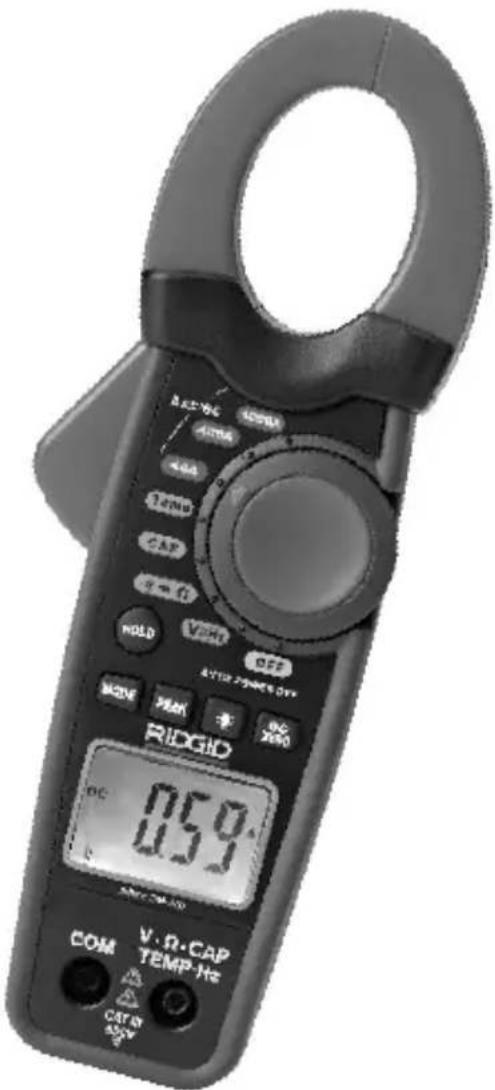
The RIDGID ^® micro CM-100 Digital Clamp Meter is a handheld digital instrument with clamp-on current measuring capability. The unit can measure DC and AC Voltage and Current, Resistance, Capacitance, Frequency, Temperature, Continuity (audible signal) and Test Diodes.
The unit has data hold, peak hold and DC Amps zero adjustment functions. Overload protection and low battery indication are provided in the unit. The unit has a four Digit backlight LCD.
The Clamp Meter is powered by a 9V battery and has auto power-off function after 20 minutes of inactivity.
Specifications
Display....4-Digit backlight LCD
Clamp Size ....1.2" (30 mm) Opening
Overvoltage Category.....CAT III 600 V, CAT II 1000 V
Safety Compliance......IEC 61010-1, EN 61010-1
Measurement Rate ....2 per Second, Nominal
Power Supply ....9V Battery, NEDA 1604, IEC 6F22 or 6LR61
Operating Temperature ....0°C to 50°C (32°F to 122°F)
Weight....0.67 lbs (304 g)
Dimension....9.0" x 3.1" x 1.9" (229 x 79 x 48 mm)
Input Limits
| Function Maximum Input | |
| Voltage V DC/AC 600 V DC/AC | |
| Current A DC/AC 1000 A DC/AC | |
| Frequency, Duty Cycle 600 V DC/AC |
Accuracy is given at 18^ C to 28^ C ( 65^ F to 83^ F), less than 70% RH
DC Current
| Range Resolution | Accuracy | |
| 40 A 0.01 A ±2.8% of Reading ± 10 Digits | ||
| 400 A 0.1 A | ±2.8% of Reading ± 8 Digits | |
| 1000 A 1 A ±3.0% of Reading ± 8 Digits | ||
AC Current
| Range Resolution Accuracy | |
| 40 A 0.01 A ±2.8% of Reading ± 10 Digits | |
| 400 A 0.1 A | ±2.8% of Reading ± 8 Digits |
| 1000 A 1 A ±3.0% of Reading ± 8 Digits | |
DC Voltage (Autoranging)
| Range Resolution Accuracy | |
| 400 mV 0.1 mV ±0.8% of Reading ±2 Digits | |
| 4 V 0.001 V | |
| 40 V 0.01 V ±1.5% of Reading ±2 Digits | |
| 400 V 0.1 V | |
| 600 V 1 V ±2.0% of Reading ±2 Digits | |
Input Impedance.....10.0 MΩ
AC Voltage (Autoranging)
| Range | Resolution | Accuracy |
| 400 mV | 0.1 mV | ±1.0% of Reading ± 10 Digits |
| 4 V | 0.001 V | ± 1.5% of Reading ± 8 Digits |
| 40 V 0.01 V | ||
| 400 V | 0.1 V | |
| 600 V | 1 V | ±2.0% of Reading ± 8 Digits |
Input Impedance.....10.0 MΩ
Resistance (Autoranging)
| Range | Resolution | Accuracy |
| 400 Ω0.1 Ω | ±1.0% of Reading ± 4 Digits | |
| 4 kΩ | 1 Ω | ±1.5% of Reading ± 2 Digits |
| 40 kΩ | 10 Ω | |
| 400 kΩ100 Ω | ||
| 4 MΩ | 1 kΩ | ±2.5% of Reading ± 5 Digits |
| 40 MΩ | 10 kΩ | ±3.5% of Reading ± 10 Digits |
Capacitance (Autoranging)
| Range Resolution | Accuracy | |
| 4 ηF 0.001 ηF ±5.0% of Reading ± 30 Digits | ||
| 40 ηF 0.01 ηF ±5.0% of Reading ± 20 Digits | ||
| 400 ηF 0.1 ηF | ||
| 4 μF 0.001 μF ±3.0% of Reading ± 5 Digits | ||
| 40 μF | 0.01 μF | |
| 400 μF | 0.1 μF | ±4.0% of Reading ± 10 Digits |
| 4 mF | 0.001 mF | ±4.5% of Reading ± 10 Digits |
| 40 mF | 0.01 mF | ±5.0% of Reading ± 10 Digits |
Frequency (Autoranging)
| Range Resolution | Accuracy | |
| 4 kHz | 0.001 kHz | ±1.5% of Reading ± 2 Digits |
Sensitivity ....>5 V RMS minimum
Temperature
| Range Resolution Accuracy | ||
| -40°C to +1000°C | 1°C | ±2.5% of Reading ± 3°C |
| -40°F to +1832°F | 1°F | ±2.5% of Reading ± 5°F |
Diode Test
| Range Resolution | Accuracy | |
| 0.3 mA Typical | 1 mV | ±10% of Reading ± 5 Digits |
Open Circuit Voltage ....1.5 V DC
Audible Continuity
Audible Threshold ....< 35 Ω
Test Current ....../< 1.0 mA
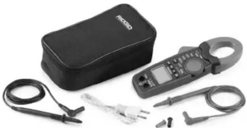
Standard Equipment
The RIDGID ^® micro CM-100 Digital Clamp Meter comes with the following items:
- micro CM-100 Digital Clamp Meter
- User Manual and Instruction CD
• Test Leads with Covers, Black and Red - Carrying Case
• K Type Adapter and Temperature Probe
natural_image
Black handheld electrical testing kit with clamp, coiled cables, and probe (no visible text or symbols)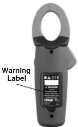
Figure 1 – micro CM-100 Digital Clamp Meter
Figure 2 – Back of micro CM-100 Digital Clamp Meter
Controls
| 1. Transformer Jaws |
| 2. Jaw Trigger |
| 3. Rotary Function switch |
| 4. Data hold pushbutton |
| 5. Mode pushbutton MODE |
| 6. Peak hold pushbutton PEAK |
| 7. Backlight pushbutton |
| 8. DC amps zero adjustment pushbutton DC |
| 9. 4-Digit Liquid Crystal Display |
| 10. Positive Input Terminal for DC/AC Voltage Measurement, Resistance Measurement, Continuity Check, Diode Test, Frequency Measurement, Capacitance Measurement and Temperature Measurement V·Ω·CAPTEMP·Hz |
| 11. COM (Negative) Terminal for all measurements COM |
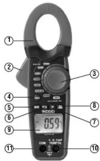
Figure 3 – micro CM-100 Digital Clamp Meter Controls
Icons
Screen Icons
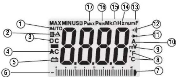
| Icon Number | Icons on Screen Description | |
| 1 AUTO | Autoranging. | |
| 2 DC Amps Zero Adjustment | ||
| 3 DC Direct Current or Voltage. | ||
| 4 AC Alternating Current or Voltage. | ||
| 5 Low Battery. |  | |
| 6 | — | Polarity Indicator. |
| 7 Analog Display of Voltage | ||
| 8 °C and °F Temperature Mode (Degree Celsius, Degree Fahrenheit). | ||
| 9 | V, mV | volts, millivolts |
| 10 |  | amperes (amps), microamp, milliamp |
| 11 |  | Diode Test Mode. |
| 12 | Continuity Check Mode. | |
| 13 μF, |  mF mF | microfarad, nanofarad, farad, millifarad |
| 14 |  | kilohertz |
| 15 | Ω,  Ω Ω | ohm, kilohm, Megohm |
| 16 | F  Peak M Peak M | Minimum Value. |
| 17 | F  | Peak Maximum Value. |
 overload overload | Condition. (Shows in Numeric Display.) | |


-100
[Non-Text]
[Non-Text]
C
①
1
)
5
©
m = 311
ons
-
[Non-Text]
[Non-Text]
[Non-Text]
-
[Non-Text]
(No text)
-
[Non-Text]
(No text)
-
[Non-Text]
(No text)
-
-100
[Non-Text]
[Non-Text]
4
。
,
)
5
©
m = 311
ons
-
[Non-Text]
[Non-Text]
[Non-Text]
-
[Non-Text]
(No text)
[Non-Text]
lam
[Non-Text]
[Non-Text]
-
MAX
田A
DC
AC
白
--||
1
-
-
[Non-Text]
[Non-Text]
[Non-Text]
m = 311
[Non-Text]
lam
[Non-Text]
[Non-Text]
-
MAX
田A
AC
白
in
...
-
-
[Non-Text]
[Non-Text]
m = 311
[Non-Text]
lam
[Non-Text]
[Non-Text]
DC
AC
白
-- III
Sons
[Non-Text]
The Ground Truth image displays a single, solid horizontal line. According to Rule 2 (UNDERSCORE & LINE RULES), this is a stylistic or background line, not a placeholder underscore. Therefore, the OCR result must ignore it and output nothing or only meaningful text. The provided OCR content is "____", which consists of four underscores. This is an incorrect interpretation of the line as a placeholder, violating the rule that stylistic lines must be ignored. The OCR has hallucinated underscores where none should exist based on the GT's visual context. Hence, the OCR result is inconsistent with the Ground Truth.
[Non-Text]
[Non-Text]
[Non-Text]
m = 311
[Non-Text]
[Non-Text]
On Product Icons
| Double Insulation Symbol | |||
| Earth Ground Symbol 9V Battery Symbol | |||
| CAT III | IEC Overvoltage Category III CAT II IEC Overvoltage Category IICAT III equipment is designed to protect against transients in equipment in fixed against transients from energy-equipment installations, such as consuming equipment supplied from distribution panels, feeders and short the fixed installation, such as TVs, PCs branch circuits, and lighting systems portable tools, and other household in large buildings. appliances. | ||
| CE | Conforms to European Union directives. | Do not dispose of electrical equipment with household waste! |
NOTICE This equipment is used to make electrical measurements. Incorrect use or improper application may result in incorrect or inaccurate measurements. Selection of appropriate measurement methods for the conditions is the responsibility of the user.
FCC Statement
This equipment has been tested and found to comply with the limits for a Class B digital device, pursuant to part 15 of the FCC Rules. These limits are designed to provide reasonable protection against harmful interference in a residential installation.
This equipment generates, uses, and can radiate radio frequency energy and, if not installed and used in accordance with the instructions, may cause harmful interference to radio communications.
However, there is no guarantee that interference will not occur in a particular installation. If this equipment does cause harmful interference to radio or television reception, which can be determined by turning the equipment off and on, the user is encouraged to try to correct the interference by one or more of the following measures:
- Reorient or relocate the receiving antenna.
- Increase the separation between the equipment and receiver.
- Consult the dealer or an experienced radio/TV technician for help.
Electromagnetic Compatibility (EMC)
The term electromagnetic compatibility is taken to mean the capability of the product to function smoothly in an environment where electromagnetic radiation and electrostatic discharges are present and without causing electromagnetic interference to other equipment.
NOTICE The RIDGID micro CM-100 Digital Clamp Meter conforms to all applicable EMC standards. However, the possibility of it causing interference in other devices cannot be precluded.
Changing/Installing Batteries
The RIDGID micro CM-100 Digital Clamp Meter is supplied without the battery installed. When the low battery [+] icon appears on the display screen, replace the battery. Operating the clamp meter with a low battery can cause incorrect readings. Remove the battery prior to long-term storage to avoid battery leakage.
-
Switch OFF the device and disconnect test leads.
-
Use a Phillips head screwdriver to loosen the battery compartment cover screw and remove the cover. Remove existing battery.
-
Install 9V alkaline battery (NEDA 1604, IEC 6F22 or 6LR61), observing the correct polarity as indicated on the battery compartment.
-
Securely install the battery compartment cover. Do not operate without the battery cover secured.
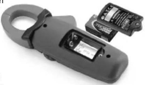
natural_image
Close-up of a black electrical clamp device with two partially visible battery modules (no text or symbols visible)Figure 5 – Changing Battery
Pre-Operation Inspection
WARNING
Before each use, inspect your tool and correct any problems to reduce the risk of serious injury from electric shock and other causes and prevent tool damage.
-
Make sure the unit is OFF and the leads are not connected.
-
Clean any oil, grease or dirt from the equipment. This aids inspection and helps prevent the tool from slipping from your grip.
-
Inspect the tool.
-
For any broken, worn, missing or binding parts or any condition which may prevent safe and normal operation.
- Confirm that battery compartment cover and back cover (fuse cover) are properly secured.
- Inspect the test leads for damaged insulation or exposed wire. Check the test leads for continuity.
- Check that the markings and warning label are present, firmly attached and readable.
If any issues are found during the inspection, do not use the tool until it has been properly serviced.
-
Verify the meter operation (following the Operating Instructions)
-
Turn the unit ON and confirm that the Low Battery icon is not ON.
• Perform a continuity test. -
Do not use the meter if it operates abnormally. When in doubt, have the meter serviced.
Set-Up and Operation
WARNING
Set up and operate the micro CM-100 Digital Clamp Meter according to these procedures to reduce the risk of injury from electric shock and other causes, and prevent tool damage.
Use caution when working with voltages above 30 V AC RMS,
42V AC peak or 60V DC. These voltages pose serious shock hazard. High-voltage circuits, both DC and AC, are very dangerous and should be measured with great care. Avoid working alone.
Do not connect to voltages that exceed 600 VAC or VDC relative to earth ground. This may damage the meter and expose the operator to a shock hazard.
When using the probes, keep your fingers behind the finger guards on the probes. This reduces the risk of electric shock.
Never ground yourself when taking electrical measurements. Do not touch exposed metal pipes, outlets, fixtures, etc., which might be at ground potential. Keep your body isolated from ground using appropriate methods.
Use extreme caution when working near bare conductors and bus bars. Accidental contact with conductors could result in electrical shock.
- Check for an appropriate work area as indicated in the General Safety section.
- Inspect the work to be done and confirm that you have correct equipment for the application. See the Specifications section for range, accuracy and other information.
- To select a function, turn the rotary function switch to the appropriate position.
- Select the proper function and range for your measurement.
- Determine the voltage to be measured. Do not apply more than the rated voltage, as marked on the meter, between terminals or between any terminal and earth ground.
- Check the clamps for full closure. Do not use the meter if the clamps do not operate properly.
-
Turn the function switch to the OFF position after inspection.
-
Make sure all equipment being used has been properly inspected.
-
Use correct accessories for the application. Select the proper terminals, function, and range for all measurements.
-
When making electrical connections, connect the common test lead (black) before connecting the live test lead (red); when disconnecting, disconnect the live test lead (red) before disconnecting the common test lead (black).
-
If "OL" appears in the display during a measurement, the value exceeds the range you have selected, change to a higher range. On some low DC and AC voltage ranges, with the test leads not connected to a device, the display may show a random, changing reading. This is normal and is caused by the high-input sensitivity. The reading will stabilize and give a proper measurement when connected to the circuit.
-
Always turn the function switch to the OFF position when the meter is not in use. The meter will automatically shut OFF if not used for 20 minutes.
Rotary Function Switch
The Rotary Function switch permits the user to select a measurement function by positioning the rotary switch to one of the icons around its perimeter.
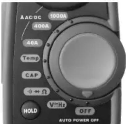
| Switch Position | Function |
| 1000A | DC/AC Current Measurement up to 1000 A |
| 400A | DC/AC Current Measurement up to 400 A |
| 40A | DC/AC Current Measurement up to 40 A |
| + | Continuity/Diode Test & Resistance Measureme |
| V=Hz | Voltage and Frequency Measurement |
| CAP | Capacitance Measurement |
| Temp | Temperature Measurement in °C or °F |
| OFF | Switch OFF the Clamp Meter |
Figure 6 – Rotary Function Switch
Input Terminals
The black test lead plugs into the negative (COM) terminal and the red test lead plug the positive terminal. The Transformer Jaw Clamp is used for DC/AC current measurement.
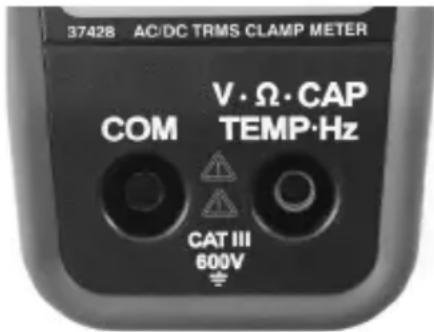
| Terminals Description |
| V / Input Positive Terminal for Voltage, Resistance, Ω/ CAP / Continuity Test, Diode Test, Capacitance, TEMP /Hz Temperature and Frequency Measurement |
| COM Negative Terminal for all measurements |
Figure 7 – Input Terminals
Pushbuttons
Mode Button
The Mode Button is used to select Ohms/Diode/Continuity, DC/AC Current and Voltage, Degrees F/C in the appropriate rotary switch settings.
- In Current measurement function, pressing the Mode button will select the AC range from the default DC range.
- In Voltage/Frequency measurement function, pressing the Mode button once will select the AC range from the default DC range. If the button is pressed for 3 seconds, the meter will enter Frequency measurement function.
- In Resistance/Diode/Continuity function, pressing the Mode button will change from default Resistance function to Diode test and then Continuity test function.
- In Temperature measurement function, pressing the Mode button will change from default °C to °F units.
Peak Hold Button
The Peak Data Hold function records the maximum and minimum readings for current and voltage on the display.
-
Press the Peak Hold button once to record the peak maximum value. The meter beeps and indicator "P MAX" appears on the display.
-
Press the Peak Hold button again to record the peak minimum value. The meter beeps and indicator "P MIN" appears on left-upper corner of the display.
-
Press the Peak Hold button for 3 seconds to deactivate.
Data Hold Button
The Data Hold function allows the meter to freeze a measurement for later reference.
-
Press the Data Hold button to freeze the reading on the indicator. The meter beeps and indicator "HOLD" appear on the display.
-
Press the Data Hold button to return to normal operation.
DC Zero Button
The DC Zero Button is used in case of DC current measurement to zero the clamp current for accurate measurement.
Backlight Button
- Press the Backlight button for 3 seconds to turn the display light ON.
- Press Backlight button again for 3 seconds to exit the backlight mode.
DC/AC Voltage Measurement
NOTICE Do not measure voltage if motor (or other high current equipment) on the circuit is being switched ON and OFF. Large voltage surge may occur that can damage the meter.
- Set the function switch to V Hz position. The meter automatically defaults to DC Voltage.
- Press button to select the AC voltage range if desired.
- Insert black test lead plug into the "COM" terminal and red test lead plug into the "V CAP TEMP Hz" terminal.
- Touch the test probe tips to the circuit under test. Be sure to observe the correct polarity (red lead to positive, black lead to negative).
The probe tips may not be long enough to contact the live parts inside some fixtures because the contacts are deeply recessed. The reading may show 0 volts when the outlet actually has voltage on it. Make sure the probe tips are touching metal contacts before assuming that no voltage is present
- Read the voltage in the display. The display will indicate the proper value with decimal point and symbol (DC/AC and V). If the polarity is reversed, the display will show minus (-) before the value.
DC/AC Current Measurement
WARNING To reduce risk of electric shock, ensure that the test leads are disconnected from the meter before making current measurements.
- Set the function switch to 40A, 400A or 1000A position according to the measurement range. The meter automatically defaults to DC current.
- Press MODE button to select the AC current range from default DC mode.
- In DC mode, press the button once, the symbol will appear indicating the display is zero.
- Press the trigger to open up the transformer jaws and clamp around the single conductor that needs to be tested.
- Read the display. The display will indicate the proper value with decimal point and symbol.
NOTE! During measurement, keep the jaws fully closed for accurate measurement. When measuring large currents, the jaws may buzz. This is not a fault and does not affect the accuracy. Fig
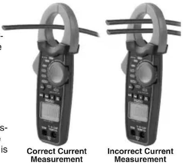
Figure 8 – Correct Way of Current Measurement
Resistance Measurement
WARNING To reduce risk of electric shock, disconnect all power (remove batteries, unplug cord, discharge all capacitors, etc.) to the circuit being measured before taking any resistance measurement.
- Set the function switch to position.
- Insert the black test lead plug into the "COM" terminal and the red test lead plug into the "V ΩCAP TEMP Hz" terminal.
- Touch the test probe tips across the circuit or part under test. It is good practice to disconnect one side of the part under test so the rest of the circuit will not interfere with the resistance reading.
- Read the resistance in the display. The display will indicate the proper value with decimal point and symbol.
- After resistance test, the capacitive circuits must be discharged. This will help protect against electric shock.
Diode Test
WARNING To reduce the risk of electric shock, do not test any diode that has voltage on it.
- Set the function switch to position.
- The meter automatically defaults to Resistance range. Press button once to select the diode test range.
- Insert the black test lead plug into the "COM" terminal and the red test lead plug into the the "V CAP TEMP Hz" terminal.
- Touch the test probe tips to the diode or semiconductor junction to test. Note the meter reading.
- Reverse the probe polarity by switching probe position. Note this reading.
- The diode or junction can be evaluated as follows:
- If one reading shows a value and the other reading shows OL, the diode is good.
- If both readings show OL, the device is open.
- If both readings are very small or 0, the device is shorted.
NOTE! The value indicated in the display during the diode check is the forward voltage.
Continuity Check
WARNING To reduce risk of electric shock, never measure continuity on circuits or wires that have voltage on them.
- Set the function switch to + position.
- The meter automatically defaults to Resistance range. Press MODE button twice to select the continuity test range.
- Insert black test lead plug into the "COM" terminal and red test lead plug into the "VΩCAP TEMP Hz" terminal.
- Check meter operation by touching probe tips together. An audible signal should sound.
- Touch the test probe tips to the circuit or wire to check.
- If the resistance is less than approximately 35 , an audible signal will sound. The display will also show the actual resistance.
Capacitance Measurement
WARNING To reduce risk of electric shock, disconnect all power (remove batteries,
unplug cord, discharge all capacitors, etc.) to the circuit being measured before taking any capacitance measurement. Use the DC Voltage function to confirm that the capacitor is discharged.
- Set the function switch to CAP position.
- Insert the black test lead plug into the "COM" terminal and the red test lead plug into the "V CAP TEMP Hz" terminal.
- Touch the test leads to the capacitor to be tested. The display will indicate the proper value with decimal point and symbol.
Frequency Measurement
- Set the function switch to V Hz position.
- The meter automatically defaults to DC voltage. Press and hold MODE button for 3 seconds to select the frequency range.
- Insert black test lead plug into the "COM" terminal and red test lead plug into the "V ΩCAP TEMP Hz" terminal.
- Touch the test probe tips to the circuit under test.
- Read the frequency in the display. The digital reading will indicate the proper value with decimal point and symbol.
Temperature Measurement
⚠ WARNING To reduce the risk of electric shock, disconnect both test probes from any source of voltage before making a temperature measurement.
- Set the function switch to Temp position. The meter automatically defaults to °C range.
- Insert the temperature adapter in "COM" and "V Ω CAP TEMP Hz" terminal with
-ve side in "COM" and +ve side in "V Ω CAP TEMP Hz" terminal.
- Insert the Temperature Probe into the adapter.
- Touch the Temperature Probe head to the part whose temperature is to be measured. Keep the probe in contact with the part under test until the reading stabilizes (about 30 seconds).
- Read the temperature in the display. The digital reading will indicate the proper value with decimal point.
- Press MODE button to change from °C to °F unit.
WARNING To reduce risk of electric shock, be Figure 9 – Temperature Probe sure the thermocouple has been removed before changing to another measurement function.
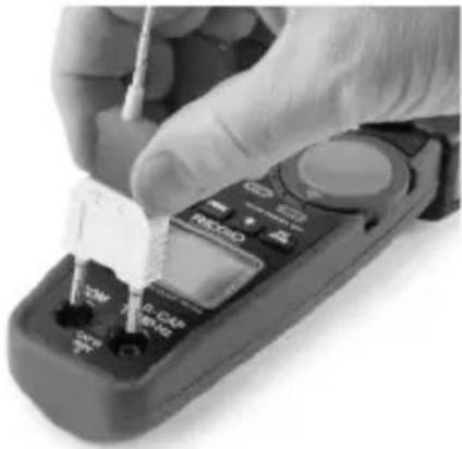
natural_image
Close-up of a gloved hand using a handheld multimeter with a tool, no visible text or symbols on the device itself.Figure 9 – Temperature Probe
Maintenance Instructions
WARNING
To reduce risk of electric shock, disconnect the test leads from any source of voltage before performing any maintenance activity.
Cleaning
- Do not immerse the clamp meter in water. Wipe off dirt with a damp soft cloth. Do not use aggressive cleaning agents or solutions. Gently clean the display screen with a clean dry cloth. Avoid rubbing too hard.
- Use only alcohol swabs to clean the test lead connections.
Calibration
The calibration of the meter should be checked once a year to ensure that it performs according to the specifications.
Accessories
WARNING
To reduce the risk of serious injury, only use accessories specifically designed and recommended for use with the RIDGID micro CM-100 Digital Clamp Meter such as those listed below. Other Accessories suitable for use with other tools may be hazardous when used with this meter.
| Catalog Number | Description |
| 44748 Test Leads with Covers, Black and Red | |
| 44758 K Type | Adapter and Temperature Probe |
Further information on accessories specific to this tool can be found in the RIDGID Catalog and online at www.RIDGID.com or www.RIDGID.eu
Storage
The RIDGID micro CM-100 Digital Clamp Meter must be stored in a dry secure area between -30^ C ( -22^ F) and 60^ C ( 140^ F) and humidity less than 85% RH.
Store the tool in a locked area out of the reach of children and people unfamiliar with the meter.
Remove the battery before any long period of storage or shipping to avoid battery leakage. The clamp meter should be protected against hard impacts, moisture and humidity, dust and dirt, extreme high and low temperatures and chemical solutions and vapors.
Service and Repair
WARNING
Improper service or repair (or calibration) can make the micro CM-100 Digital Clamp Meter unsafe to operate.
Service and repair of the micro CM-100 Digital Clamp Meter must be performed by a RIDGID Independent Authorized Service Center.
For information on your nearest RIDGID Independent Service Center or any service or repair questions:
- Contact your local RIDGID distributor.
- Visit www.RIDGID.com or www.RIDGID.eu to find your local RIDGID contact point.
- Contact Ridge Tool Technical Service Department at rttechservices@emerson.com, or in the U.S. and Canada call (800) 519-3456.
Disposal
Parts of the RIDGID micro CM-100 Digital Clamp Meter contain valuable materials and can be recycled. There are companies that specialize in recycling that may be found locally. Dispose of the components in compliance with all applicable regulations. Contact your local waste management authority for more information.
For EC Countries: Do not dispose of elec trical equipment with household waste!
According to the European Guideline 2002/96/EC for Waste Electrical and Electronic Equipment and its implementation into national legislation, electrical equipment that is no longer usable must be collected separately and disposed
of in an environmentally correct manner.
Battery Disposal
For EC countries: Defective or used batteries must be recycled according to the guideline 2006/66/EEC.
Troubleshooting
| SYMPTOM POSSIBLE REASON SOLUTION | ||
| Meter does not work properly. | Battery low on power. | Replace battery. |
| Meter needs calibration. | Send the unit for calibration | |
| Meter not set for proper measurement. | Move the Rotary Function Switch according to the correct measurement. | |
| Use of incorrect input terminal, range or mode for measurement. | Use proper input terminal, range or mode for measurement. See Tool Set-up and Operating Instructions. | |
| Unit will not turn ON. | Dead battery. | Replace battery. |
natural_image
Close-up of a black handheld electrical clamp device with visible battery and accessories (no text or symbols)Figure 5 – Remplacement des piles
natural_image
Close-up of a hand using a handheld multimeter with a screwdriver, no visible text or symbols on the device itself.natural_image
Black handheld electrical clamp kit with coiled wires and a digital display (no visible text or symbols)natural_image
Close-up of a black electrical clamp device with two partially open batteries (no visible text or symbols)natural_image
Close-up of a gloved hand using a handheld multimeter with a screwdriver inserted (no visible text or symbols)Figure 9 – Borne de temperatura
natural_image
Close-up of a black electrical clamp device with attached electronic components (no visible text or symbols)natural_image
Close-up of a handheld clamp meter with digital display and control knobs (no visible text or symbols)natural_image
Digital clamp meter with a digital display and metal contacts (no visible text or symbols)natural_image
Close-up of a hand using a handheld multimeter to test a small component (no visible text or symbols)Specifications....81
Standaarduitrusting....84
Bedieningselementen....84
Pictogrammen 85
FCC-verklaring....86
Elektromagnetische compatibiliteit (EMC)......86
Installeren/vervangen van de batterijen....86
DC/AC Spanning meten....90
DC/AC Stroom meten....91
Weerstand meten 91
Diodetest....91
Doorgangsmeting....92
Teststroom ....../< 1,0 mA
Standaarduitrusting
natural_image
Product display of micro CM-100 digitale stroomtang tool and clamp (no text or symbols on main components)natural_image
Close-up of a black electrical clamp device with two partially visible components (no text or symbols visible)natural_image
Two identical flat-tacsim pliers with digital displays and metal clamps, shown side by side (no visible text or symbols)natural_image
Close-up of a hand using a handheld multimeter to test or inspect the function (no visible text or symbols)natural_image
Close-up of a black electrical clamp device with attached electronic components (no visible text or symbols)natural_image
Close-up of a hand using a handheld multimeter to test or inspect the dial (no visible text or symbols)natural_image
Product display of a CM-100 micro digital clamp with circuit board, power cord, and clamp meter (no visible text or symbols)Figura 1 - Controlos do Amperímetro Digital CM-100 micro Figura 2 - Parte traseira do Amperímetro Digital CM-100 micro
Controlos
natural_image
Close-up of a black electrical clamp device with two internal components (no visible text or symbols)natural_image
Close-up of a hand using a handheld multimeter to test or inspect the component (no visible text or symbols)Figura 9 - Sonda de temperatura
natural_image
Product display of micro CM-100 digital tanganmultimeter with clamp and test equipment (no visible text or symbols on main components)Figur 1 – micro CM-100 Digital tångmultimeter Figur 2 – micro CM-100 Digital tångmultimeter, baksida
Reglage
natural_image
Close-up of a black electrical clamp device with attached electronic components (no visible text or symbols)Figur 5 - Byta batteri
natural_image
Close-up of a hand using a handheld multimeter to test or adjust a component (no visible text or symbols)Figur 9 – Temperaturprob
Teststrøm....< 1,0 mA
Standardudstyr
Det digitale tangmeter RIDGID® micro CM-100 omfatter følgende:
natural_image
Product photo of micro CM-100 digital clamp meter with clamps, a handheld device, and coiled cables (no visible text or symbols)Fig. 1 – micro CM-100 digitalt tangmeter
Fig. 2 – Bagsiden af det digitale tangmeter micro CM-100
natural_image
Close-up of a black electrical clamp with visible internal components and battery modules (no text or symbols)natural_image
Close-up of a hand using a handheld multimeter to test or adjust a small electronic device (no visible text or symbols)Teststrøm....< 1,0 mA
Standardutstyr
RIDGID® micro CM-100 Digitalt tangamperemeter leveres med de følgende delene:
natural_image
Product photo of micro CM 100 digital tangle meter and clamp (no visible text or symbols)Figur 1 - micro CM-100 Digitalt tangamperemeter
Figur 2 – Baksiden til micro CM-100 Digitalt tangamperemeter
Kontoller
natural_image
Close-up of a black electrical clamp device with attached electronic components (no visible text or symbols)Figur 5 – Skifte batteri
Inspeksjon før bruk
ADVARSEL

natural_image
Two identical handheld clamp meters with digital displays and metal clamps (no visible text or symbols)natural_image
Close-up of a hand using a handheld multimeter to test a small component (no visible text or symbols)Figur 9 - Temperaturprobe
Testivirta ....../< 1,0 mA
Vakiovarusteet
natural_image
Product photo of micro CM-100 digital measuring tools including a clamp meter, circuit board, and clamp meter (no visible text or symbols on main components)natural_image
Close-up of a black electrical clamp device with two partially visible battery modules (no text or symbols visible)natural_image
Close-up of a hand using a multimeter to test or inspect the function (no visible text or symbols)natural_image
Black handheld electrical clamp meter with coiled wires and a digital display, no visible text or symbols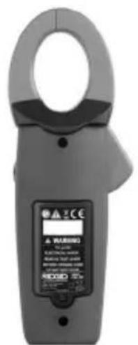
natural_image
Close-up of a black electrical clamp device with internal components and a partially open top panel (no visible text or symbols)natural_image
Digital clamp meter with LCD display and probe strap (no visible text or symbols)natural_image
Digital clamp meter with dual leads and a digital display (no visible text or symbols)natural_image
Close-up of a hand using a handheld multimeter to test or adjust a component (no visible text or symbols)natural_image
Product display of a handheld clamp meter and its corresponding digital clamp meter (no visible text or symbols on main components)natural_image
Close-up of a black handheld electrical clamp with visible internal components and battery casing (no text or symbols)natural_image
Close-up of a hand using a multimeter to test a small component (no visible text or symbols)TIETO POKYNY USCHOVAJTE!
TIETO POKYNY USCHOVAJTE!
natural_image
Product photo of a digital micro-CP 100 clamp meter with labeled components and a close-up of the clamp (no visible text or symbols on main objects)natural_image
Close-up of a black electrical clamp device with visible battery and internal components (no text or symbols)natural_image
Close-up of a hand using a multimeter to test a small electronic component (no visible text or symbols)Current testare ....../< 1,0 mA
natural_image
Product display of a micro CM-100 clamp meter and its corresponding circuitry device (no text or symbols on main components)Figura 1 – Cleştele de curent digital micro CM-100
Figura 2 – Spatele cleștelui de curent digital micro CM-100
Comenzile
natural_image
Close-up of a black handheld electrical clamp with two partially visible battery modules (no text or symbols visible)natural_image
Close-up of a hand using a handheld multimeter to test or inspect the component (no visible text or symbols)natural_image
Black handheld electrical clamp kit with coiled test probes and a digital display (no visible text or symbols)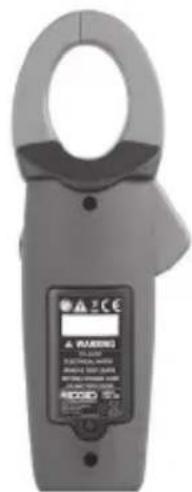
natural_image
Close-up of a black electrical clamp device with attached battery and switch (no visible text or symbols)- ábra – Elemcsere
natural_image
Two identical handheld pliers with digital displays and metal contacts, shown side by side (no visible text or symbols)natural_image
Close-up of a gloved hand using a handheld multimeter to test or inspect the internal components (no visible text or symbols)natural_image
Close-up of a black electrical clamp device with attached circuit boards (no visible text or symbols)natural_image
Close-up of a hand using a handheld multimeter to test or adjust a small component (no visible text or symbols)Mjerna struja ....../< 1,0 mA
Standardna oprema
natural_image
Product display of a micro CM-100 digital clamp meter and its corresponding circuit board (no visible text or symbols on main components)natural_image
Close-up of a black handheld electrical clamp with visible battery and circuit components (no text or symbols)Slika 5 – Zamjena baterije
Mjerenje temperature
natural_image
Close-up of a hand using a handheld multimeter to test or inspect the component (no visible text or symbols)Slika 9 – Temperaturna sonda
Upute za održavanje
UPOZORENJE
natural_image
Product display of a micro CM-100 digital clamp meter and its corresponding circuit board (no visible text or symbols on main components)natural_image
Close-up of a black electrical clamp device with two partially open buttons and a battery cover (no visible text or symbols)Slika 5 – Zamenjava baterije
natural_image
Close-up of a hand using a handheld multimeter to test or inspect the component (no visible text or symbols)Slika 9 – Temperaturna sonda
natural_image
Product display of micro CM-100 digital probe kit and clamp (no visible text or symbols)Slika 1 – micro CM-100 digitalna strujna klešta
Slika 2 – Pozadina micro CM-100 digitalnih strujnih klešta
natural_image
Close-up of a black electrical clamp device with attached electronic components (no visible text or symbols)Slika 5 – Zamena baterije
Pregled pre upotrebe
UPOZORENJE

Pre svake upotrebe pregledajte merni instrument i otklonite sve probleme da biste smanjili rizik od teške povrede usled strujnog udara i drugih uzroka i sprečili oštećenje alata.
- Uverite se da je jedinica isključena i da provodnici nisu spojeni.
- Očistite bilo koje ulje ili prljavštinu sa opreme. Ovo olakšava pregled i pomaže u zaštiti alata od klizanja u vašim rukama.
- Proverite alat.
- Na prisustvo slomljenih, pohabanih, nedostajućih ili povezanih delova ili na bilo koje drugo stanje, koje može da spreči bezbedan i normalan rad.
-
Uverite se da su poklopac odeljka za bateriju i zadnji poklopac pravilno osigurani.
-
Izvršite kontrolu provodnika na oštećenja izolacije ili ogoljene žice. Obavite testiranje provodnika na neprekidnost.
- Proverite da li postoje nalepnice sa oznakama i upozorenjima i da li su čvrsto pričvršćene i čitljive.
natural_image
Close-up of a hand using a handheld tool to apply electrical component (no visible text or symbols)Slika 9 - Temperaturna sonda
Uputstva za održavanje
UPOZORENJE
natural_image
Close-up of a black clamp meter with two partially open buttons and a battery cover (no visible text or symbols)natural_image
Two identical handheld clamp meters (SCG0 and SDG0) with digital displays, no visible text or symbols on the devices themselves.natural_image
Close-up of a hand using a handheld multimeter to test or inspect the function (no visible text or symbols)natural_image
Product display of a micro-CP 100 Dijital Pens Ampermetre tool, including clamp meter, case, and clamp meter (no visible text or symbols on main components)natural_image
Close-up of a black electrical clamp device with visible internal components (no text or symbols)natural_image
Close-up of a hand using a handheld multimeter to apply electrical components (no visible text or symbols)Elyria, Ohio 44035-6001
U.S.A.
Authorized Representative:
RIDGE TOOL EUROPE N.V.
Schurhovenveld 4820
3800 Sint-Truiden
Belgium
CE Conformity
This instrument complies with the European Council Electromagnetic Compatibility Directive 2004/108/EC using the following standards: EN 61326-1:2006, EN 61326-2-1:2006.
Conformité CE
Ridge Tool Europe NV (RIDGID)
Schurhovenveld 4820
3800 Sint-Truiden
Belgium
©2013. 2016, RIDGID. Inc.
Printed 11/16 999-999-456.09 The Emerson logo and RIDGID logo are registered trademarks of Emerson Electric Co. or
EC42556 REV. B
RIDGID, Inc. in the U.S. and other countries.
All other trademarks belong to their respective holders.
- General Safety Rules
- Specific Safety Information
- Description, Specifications and Standard Equipment
- Set-Up and Operation
- Maintenance Instructions
- micro CM-100 Digital Clamp Meter
- RIDGID®
- Safety Symbols
- DANGER
- WARNING
- CAUTION
- NOTICE
- SAVE THESE INSTRUCTIONS!
- Work Area Safety
- Electrical Safety
- Personal Safety
- Equipment Use and Care
- Service
- Digital Clamp Meter Safety
- Description, Specifications And Standard Equipment Description
- Specifications
- Audible Continuity
- Standard Equipment
- Controls
- FCC Statement
- Electromagnetic Compatibility (EMC)
- Changing/Installing Batteries
- Pre-Operation Inspection
- Rotary Function Switch
- Input Terminals
- Pushbuttons
- Mode Button
- Peak Hold Button
- Data Hold Button
- DC Zero Button
- Backlight Button
- DC/AC Voltage Measurement
- DC/AC Current Measurement
- Resistance Measurement
- Diode Test
- Continuity Check
- Capacitance Measurement
- Frequency Measurement
- Temperature Measurement
- Cleaning
- Calibration
- Accessories
- Storage
- Service and Repair
- Disposal
- Battery Disposal
- Standaarduitrusting
- Controlos
- Reglage
- Standardudstyr
- Standardutstyr
- Kontoller
- Inspeksjon før bruk
- ADVARSEL
- Vakiovarusteet
- TIETO POKYNY USCHOVAJTE!
- Comenzile
- Standardna oprema
- Mjerenje temperature
- Upute za održavanje
- UPOZORENJE
- Pregled pre upotrebe
- Uputstva za održavanje
- Authorized Representative:
- CE Conformity
- Conformité CE
Brand : RIDGID
Model : Micro CM-100
Category : Measuring equipment