
Micro LM400 - Measuring equipment RIDGID - Free user manual and instructions
Find the device manual for free Micro LM400 RIDGID in PDF.
| Product Type | Laser Distance Measurer |
| Brand | RIDGID |
| Model | Micro LM400 |
| Dimensions | 137 x 57 x 31 mm (5 3/8 x 2 1/4 x 1 7/32 inches) |
| Weight | 160 g (0.35 lb) |
| Power Supply | 2 AA 1.5 V type LR06 batteries |
| Battery Life | Up to 8,000 measurements |
| Range | 5 cm to 100 m (2 inches to 328 feet) |
| Accuracy | ± 1.5 mm (± 0.06 inches) at 10 m |
| Measurement Units | m, inches, feet |
| Laser Class | II (635 nm, < 1 mW) |
| Tilt Measurement | ± 65°, accuracy ± 0.5° |
| Wireless Communication | Bluetooth (range 10 m) |
| Memory | Last 20 measurements |
| Ingress Protection | IP54 (dust and splash resistant) |
| Operating Temperature | 0°C to 40°C (32°F to 104°F) |
| Auto Shut-off | Laser: 30 s, device: 3 min |
| Main Functions | Distance, area, volume, indirect measurements (2/3 points), tilt, stakeout, addition/subtraction, continuous measurement, timer, backlight, beep |
| Maintenance and Cleaning | Clean with a soft damp cloth; do not immerse; do not use solvents |
| Safety | Class II laser – do not stare into beam, do not point at eyes; use according to instructions |
| Spare Parts and Repairability | Have it serviced by a RIDGID authorized repair center; use only genuine parts |
| Included Accessories | Case, instruction CD, 2 AA batteries |
| Warranty | Lifetime warranty (product lifetime) |
| Country of Origin | China |
| Compliance | CE, FCC |
Frequently Asked Questions - Micro LM400 RIDGID
User questions about Micro LM400 RIDGID
0 question about this device. Answer the ones you know or ask your own.
Ask a new question about this device
Download the instructions for your Measuring equipment in PDF format for free! Find your manual Micro LM400 - RIDGID and take your electronic device back in hand. On this page are published all the documents necessary for the use of your device. Micro LM400 by RIDGID.
USER MANUAL Micro LM400 RIDGID
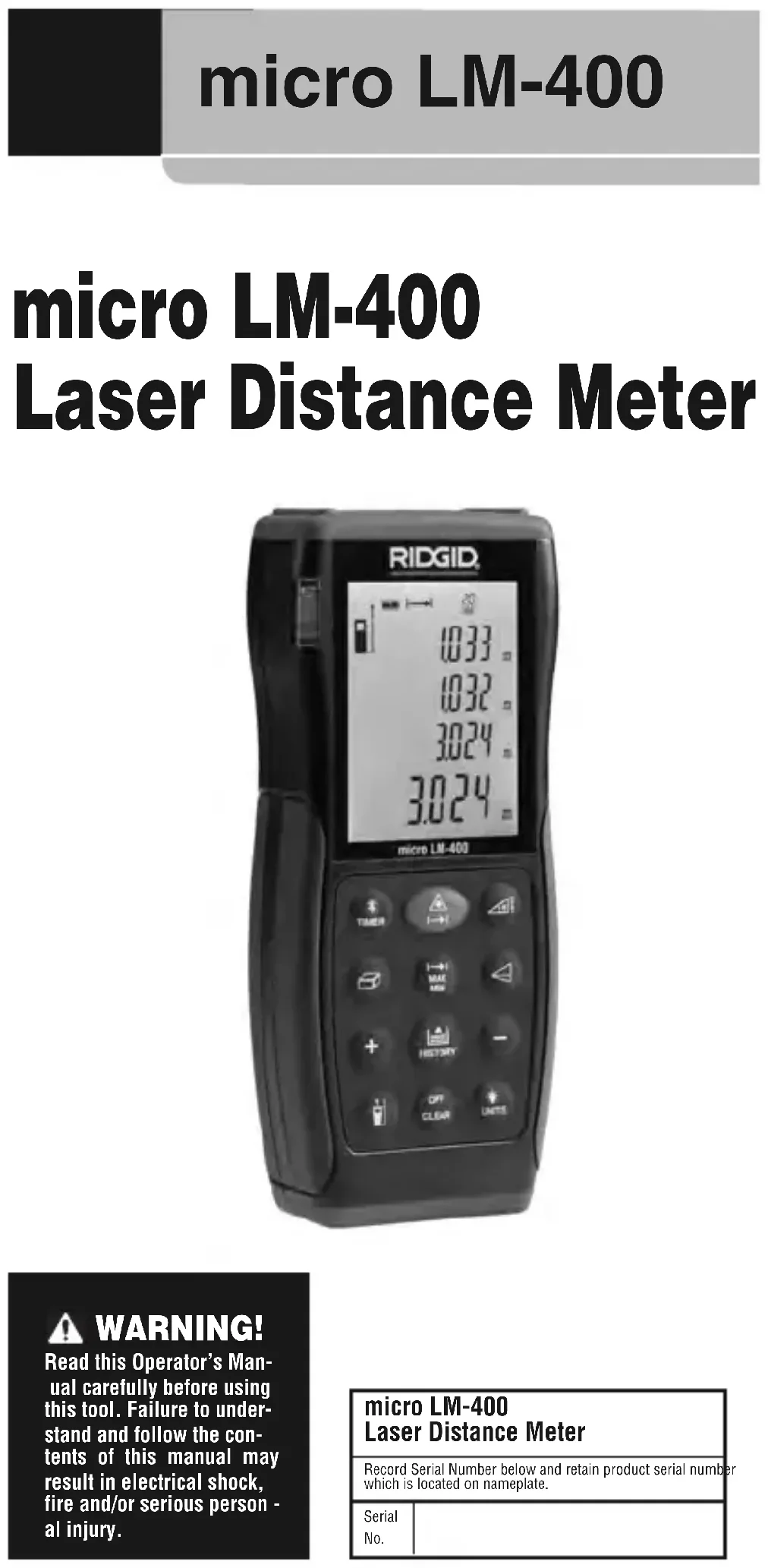
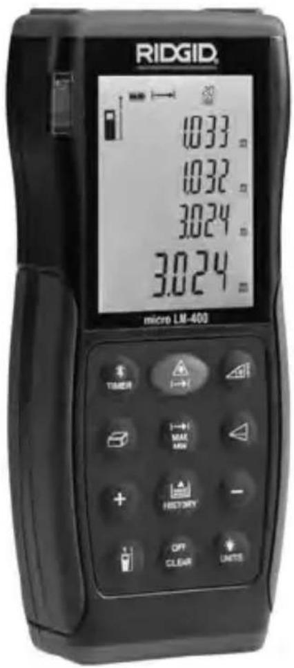
micro LM-400 Laser Distance Meter
Operator's Manual
- Français – 19
Recording Form for Machine Serial Number....1
Safety Symbols....2
General Safety Rules
Work Area Safety 2
Electrical Safety....2
Personal Safety 3
Equipment Use and Care 3
Service 3
Specific Safety Information
Laser Distance Meter Safety 4
Description, Specifications and Standard Equipment
Description 4
Specifications 4
Standard Equipment....5
Controls....5
Icons....6
Laser Classification....6
FCC Statement......7
Electromagnetic Compatibility (EMC)....7
Changing/Installing Batteries 7
Pre-Operation Inspection....7
Set-Up and Operation....8
micro LM-400 Controls and Settings 9
Turning ON and OFF....9
Changing Display Units....9
Setting Measurement Reference Point....9
Clearing Displayed Data/Last Action 9
Reviewing the Last 20 Measurements 9
Clearing Data from Memory 9
Backlighting the Display 9
Timer (Self-Triggering)....9
Wireless Data Transfer....10
Measurements....10
Single Distance Measurement....11
Continuous Measurement, Max and Min Measurement .....11
Adding/Subtracting Measurements....11
Area Measurement 11
Volume Measurement 11
Indirect Measurements....12
Using Two Points 12
Using Three Points (Total Height) 12
Using Three Points (Partial Height) 13
Indirect Measurements With Inclination Sensor 13
Indirect Horizontal Distance....14
Indirect Vertical Distance 14
Indirect Vertical Distance Using Two Points (Total Height)....15
Indirect Vertical Distance Using Two Points (Partial Height) 15
Stake Out Measurement....16
Cleaning....16
Storage 16
Service and Repair ....17
Disposal....17
Battery Disposal 17
Troubleshooting – Error Codes ....18
EC Declaration of Conformity....Inside Back Cover
Lifetime Warranty ....Back Cover
*Original instructions - English
micro LM-400
micro LM-400 Laser Distance Meter


WARNING!
Read this Operator's Manual carefully before using this tool. Failure to understand and follow the contents of this manual may result in electrical shock, fire and/or serious personal injury.
| micro LM-400Laser Distance Meter | |
| Record Serial Number below and retain product serial numbe which is located on nameplate. | |
| SerialNo. | |
Safety Symbols
In this operator's manual and on the product, safety symbols and signal words are used to communicate important safety information. This section is provided to improve understanding of these signal words and symbols.

This is the safety alert symbol. It is used to alert you to potential personal injury hazards. Obey all safety messages that follow this symbol to avoid possible injury or death.
DANGER
DANGER indicates a hazardous situation which, if not avoided, will result in death or serious injury.
WARNING
WARNING indicates a hazardous situation which, if not avoided, could result in death or serious injury.
CAUTION
CAUTION indicates a hazardous situation which, if not avoided, could result in minor or moderate injury.
NOTICE
NOTICE indicates information that relates to the protection of property.

This symbol means read the operator's manual carefully before using the equipment. The operator's manual contains important information on the safe and proper operation of the equipment.

This symbol means this device contains a Class 2 Laser.

This symbol means do not stare into the laser beam.

This symbol warns of the presence and hazard of a laser beam.
General Safety Rules
WARNING
Read all safety warnings and in struc tions. Failure to follow the warn ings and instructions may result in electric shock, fire and/or serious injury.
SAVE THESE INSTRUCTIONS!
Work Area Safety
- Keep your work area clean and well lit. Cluttered or dark areas invite accidents.
- Do not operate equipment in explosive atmospheres, such as in the presence of flammable liquids, gases or dust. E quip ment can create sparks which may ignite the dust or fumes.
- Keep children and by-standers away while operating equipment. Distractions can cause you to lose control.
Electrical Safety
- Avoid body contact with earthed or grounded surfaces such as pipes, radiators, ranges and refrigerators. There is an increased risk of electrical shock if your body is earthed or grounded.
- Do not expose equipment to rain or wet conditions. Water entering equipment will increase the risk of electrical shock.
Personal Safety
- Stay alert, watch what you are doing and use common sense when operating equipment. Do not use equipment while you are tired or under the influence of drugs, alcohol or medication. A moment of inattention while operating equipment may result in serious personal injury.
- Use personal protective equipment. Always wear eye protection. Protective equipment such as protective gloves and clothing, dust mask, non-skid safety shoes, hard hat, or hearing protection used for appropriate conditions will reduce personal injuries.
- Do not overreach. Keep proper footing and balance at all times. This enables better control of the equipment in unexpected situations.
Equipment Use and Care
- Do not force equipment. Use the correct equipment for your application. The correct equipment will do the job better and safer at the rate for which it is designed.
- Do not use equipment if the switch does not turn it ON and OFF. Any tool that cannot be controlled with the switch is dangerous and must be repaired.
- Disconnect the batteries from the equipment before making any adjustments, changing accessories, or storing. Such preventive safety measures reduce the risk of injury.
- Store idle equipment out of the reach of children and do not allow persons unfamiliar with the equipment or these instructions to operate the equipment. Equipment can be dangerous in the hands of untrained users.
- Maintain equipment. Check for missing parts, breakage of parts and any other condition that may affect the equipment's operation. If damaged, have the equipment repaired before use. Many accidents are caused by poorly maintained equipment.
- Use the equipment and accessories in accordance with these instructions, taking into account the working conditions and the work to be performed. Use of the equipment for operations different from those intended could result in a hazardous situation.
- Use only accessories that are recommended by the manufacturer for your equipment. Accessories that may be suitable for one piece of equipment may become hazardous when used with other equipment.
- Keep handles dry and clean; free from oil and grease. Allows for better control of the equipment.
Service
- Have your equipment serviced by a qualified repair person using on ly identical replacement parts. This will ensure that the safety of the tool is maintained.
Specific Safety Information
WARNING
This section contains important safety information that is specific to this inspection tool.
Read these precautions carefully before using the RIDGID ^® micro LM-400 Laser Distance Meter to reduce the risk of eye injury or other serious injury.
SAVE THESE INSTRUCTIONS!
Keep this manual with the tool for use by the operator.
Laser Distance Meter Safety
- Do not look into the laser beam. Looking into the laser beam may be hazardous to the eyes. Do not look at the laser beam with optical aids (such as binoculars or telescopes).
- Do not direct the laser beam towards other people. Make sure the laser is aimed above or below eye level. Laser beams may be hazardous to the eyes.
- Do not use the micro LM-400 as control device. Only use as a measuring device. This will reduce the risk of damage or injury in case of low batteries, malfunction or false measurement.
CAUTION Use of controls or adjustments or performance of procedures other than those specified herein may result in hazardous radiation exposure.
If you have any question concerning this RIDGID product:
- Contact your local RIDGID distributor.
- Visit RIDGID.com to find your local RIDGID contact point.
- Contact Ridge Tool Technical Service Department at rttechservices@emer-son.com, or in the U.S. and Canada call (800) 519-3456.
Description, Specifications And Standard Equipment
Description
The RIDGID® micro LM-400 Laser Distance Meter provides simple, quick, and accurate distance readings at the push of a button. You simply push the measurement button to turn on the class II laser and point it at the surface to be measured to, and then push the measurement button again.
The micro LM-400 provides a quick measurement on a clear easy to read backlit LCD display. The unit provides distance, area, volume, angle and stake out measurements. The unit is also enabled with Bluetooth wireless technology and self-timer functions.
Specifications
Range ......2 in to 328 ft* (0.05 to 100 m*)
Measuring Accuracy
Up To 10m (2) .....Typically ± 0.06 in** (±1.5mm**)
Measuring Units......m, in, ft
Angle Measurement Range± 65°
Angle Accuracy
2σ....±0.5°
Laser Type ....635 nm, <1 mW
Bluetooth Range......33 ft (10 m)
Ingress Protection ......IP 54 Dust Proof, Splash Proof
Memory ......20 Measurements
Operating Temperature.....32°F to 104°F (0°C to 40°C)
Batteries....2 x 1.5V, Type AA (LR06)
Battery Life.....Up to 8,000 Measurements
Auto. Laser Switch-Off ......After 30 Seconds
Auto. Shut-Off ......After 3 Minutes of Inactivity
Dimension....5 3/8" x 2 /4" x 17/32" (137 x 57 x 31 mm)
Weight 0.35 lbs (160 g)
* Range is limited to 328 ft (100 m). Use a commercially available target plate to improve measurement ability during daylight or if the target has poor reflective properties.
** In favorable conditions (good target surface properties, room temperature) up to 33 ft (10 m). In unfavorable conditions, such as intense sunshine, poorly reflecting target surface or high temperature variations, the deviation over distances above 33 ft (10 m) can increase by ±0.0018 in/ft (±0.15mm/m).
Features
• Distance, Area, Volume Calculations
• Continuous Measurement
- Min/Max Distance Tracking
- Indirect Measurement, Using 2 or 3 Measurements
- Addition/Subtraction
• Stake Out Measurement
- Angle Measurement
- Beep Indication
• Display Illumination and Multi-line Display
- Self-Timer
- Bluetooth® wireless technology
Standard Equipment
The RIDGID ^® micro LM-400 Laser Distance Meter comes with the following items:
- micro LM-400 Laser Distance Meter
- User Manual and Instruction CD
- Two 1.5 V, Type AA Batteries
- Carrying Case
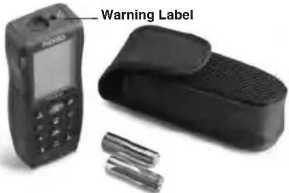
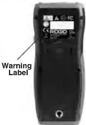
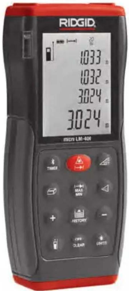
Figure 1 – micro LM-400 Laser Distance Meter
Figure 2 – Back of micro LM-400 Laser Distance Meter
Controls
| 1. ON/MEAS Button |
| 2. Bluetooth/Timer Button |
| 3. MIN-MAX Button |
| 4. Area/Volume Button |
| 5. Addition (+) Button |
| 6. Reference Button |
| 7. Angle/Stake Out Button |
| 8. Indirect Measurement Button |
| 9. History Button |
| 10. Subtraction (-) Button |
| 11. Illuminating/UNITS Button |
| 12. Clear/OFF Button |
| 13. Side MEAS Button |
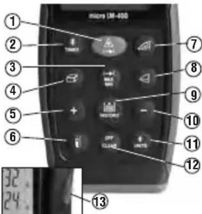
Figure 3 – micro LM-400 Laser Distance Meter Controls
Icons
Display Icons
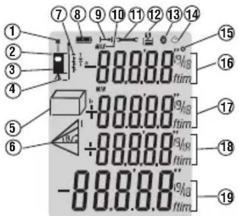
| Icon Number | Icons on Screen Description | |
| 1 Laser Active | ||
| 2 Reference Level (Front) | ||
| 3 Reference Level (Rear) | ||
| 4 Reference Level (Tripod) | ||
| 5 | Area Measurement | |
| Volume Measurement | ||
| 6 | Single Pythagorean Measurement | |
| Double Pythagorean Measurement | ||
| Double Pythagorean (Partial Height) Measurement | ||
| Angle Measurement | ||
| 7 Stake Out Function | ||
| 8 Battery Status | ||
| 9 Single Distance Measurement | ||
| 10 Max And Min Measurement | ||
| 11 Instrument Error Warning | ||
| 12 Historical Memory | ||
| 13 Bluetooth Symbol | ||
| 14 Timer | ||
| 15 Angle | ||
| 16 — Intermediate Line 1 (Intermediate Value 1 with Unit) | ||
| 17 — Intermediate Line 2 (Intermediate Value 2 with Unit) | ||
| 18 — Intermediate Line 3 (Intermediate Value 3 with Unit) | ||
| 19 — Summary Line (Final Value with Unit) | ||
Figure 4 – Screen Icons
NOTICE This equipment is used to make distance measurements. Incorrect use or improper application may result in incorrect or inaccurate measurements. Selection of appropriate measurement methods for the conditions is the responsibility of the user.
Laser Classification
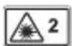
The RIDGID micro LM-400 Laser Distance Meter generates a visible laser beam that is emitted from the top of the device.
The device complies with class 2 lasers according to: IEC 60825-1:2007.
FCC Statement
This equipment has been tested and found to comply with the limits for a Class B digital device, pursuant to part 15 of the FCC Rules. These limits are designed to provide reasonable protection against harmful interference in a residential installation.
This equipment generates, uses, and can radiate radio frequency energy and, if not installed and used in accordance with the instructions, may cause harmful interference to radio communications.
However, there is no guarantee that interference will not occur in a particular installation.
If this equipment does cause harmful interference to radio or television reception, which can be determined by turning the equipment off and on, the user is encouraged to try to correct the interference by one or more of the following measures:
- Reorient or relocate the receiving antenna.
- Increase the separation between the equipment and receiver.
- Consult the dealer or an experienced radio/TV technician for help.
Electromagnetic Compatibility (EMC)
The term electromagnetic compatibility is taken to mean the capability of the product to function smoothly in an environment where electromagnetic radiation and electrostatic discharges are present and without causing electromagnetic interference to other equipment.
NOTICE The RIDGID micro LM-400 Laser Distance Meter conforms to all applicable EMC standards. However, the possibility of it causing interference in other devices cannot be precluded.
Changing/Installing Batteries
The RIDGID LM-400 Laser Distance Meter is supplied without the battery installed. When the low battery [☐] icon flashes on the display screen, replace the batteries. Operating the tool with low battery can cause incorrect readings. Remove the batteries prior to long-term storage to avoid battery leakage.
- Switch OFF the device.
- Slide the battery compartment cover release to the right to remove it. Remove existing batteries.
- Install two AA (LR06) alkaline batteries, observing the correct polarity as indicated shown in Figure 5.
NOTICE Use batteries that are of the same type. Do not mix battery types. Do not mix new and used batteries. Mixing batteries can cause overheating and battery damage.
- Securely install the battery compartment cover. Do not operate without the battery cover secured.
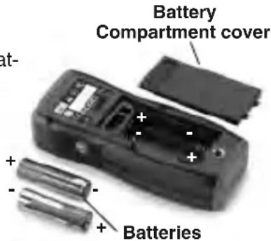
Figure 5 – Changing Batteries
Pre-Operation Inspection
WARNING
Before each use, inspect your distance meter and correct any problems to reduce the risk of injury or incorrect measurements.
Do not look into the laser beam. Looking into the laser beam may be hazardous to the eyes.
-
Make sure the unit is OFF.
-
Clean any oil, grease or dirt from the equipment. This aids inspection and helps prevent the tool from slipping from your grip.
-
Inspect the tool:
- For any broken, worn, missing or binding parts or any condition which may prevent safe and normal operation.
- Confirm that battery compartment cover is properly secured.
- Check that the markings and warning label are present, firmly attached and readable.
If any issues are found during the inspection, do not use the tool until it has been properly serviced.
- Verify the distance meter operation.
- Following the Set-Up and Operation Instructions, Turn the unit ON and confirm that the Low Battery icon is not ON.
- Make a measurement and confirm the same measurement with another instrument (tape measure, etc.). If the correlation between the measurements is not acceptable, do not use the distance meter until it has been properly serviced.
- Do not use the distance meter if it operates abnormally. When in doubt, have the meter serviced.
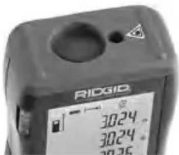
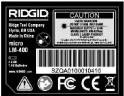
Figure 6 – Warning Labels
Set-Up and Operation
WARNING

Do not look into the laser beam. Looking into the laser beam may be hazardous to the eyes. Do not look at the laser beam with optical aids (such as binoculars or telescopes)
Do not direct the laser beam towards other people. Make sure the laser is aimed above or below eye level. Laser beams may be hazardous to the eyes.
Do not use the micro LM-400 as control device. Only use as a measuring device. This will reduce the risk of damage or injury in case of low batteries, malfunction or false measurement.
Set up and operate the distance meter according to these procedures to reduce the risk of injury or incorrect measurements.
-
Check for an appropriate work area as indicated in the General Safety Rules section.
-
Inspect the object being measured to and confirm that you have correct equipment for the application. The micro LM-400 Laser Distance Meter is designed to measure distances up to 328 feet (100 m). See the Specifications section for range, accuracy and other information.
- Make sure all equipment being used has been properly inspected.
micro LM-400 Controls and Settings
Turning ON and OFF
Press the ON/Measurement Button ( ) to turn ON the distance meter and the laser. Make sure that the laser is pointed in a safe direction before turning ON.
Press and Hold the Clear/OFF ( ) Button to turn the Distance meter OFF. The laser distance meter will turn OFF automatically after three minutes of inactivity.
Changing Display Units
Press and Hold the Backlight/Unit Change Button (+) to change the display units. Available Units are Feet, Meter and Inches.
Setting Measurement Reference Point
- When the distance meter is turned ON, the default measurement reference point is the back edge of the meter (6).
- Press the Measurement Reference Point Button ( ) to change the measurement reference point to the front edge (laser end) of the meter. The meter will beep and the display will show the reference point front symbol ( ).
- The reference can be adjusted to take measurements with a tripod. The reference on the tripod can be switched ON or OFF by pressing and holding the Measurement Reference Point Button. The meter will beep and the display will show symbol ( ).
Clearing Displayed Data/Last Action
Press the Clear/OFF Button (OK) to clear the displayed data or cancel the last action.
Reviewing the Last 20 Measurements
Press the History Button (✗) to review the last twenty measurements or calculated results, shown in reverse order. Historical memory position will be shown on the upper edge of the display for each measurement. Alternatively, you can use the Addition (✗) or Subtraction (−) Buttons to move through these records.
Clearing Data from Memory
Press and Hold the History Button ( ) and Press and Hold the Clear/OFF Button ( ) at the same time to clear all data in the memory.
Backlighting the Display
Press the Backlight/Units Button (a) to turn the display backlight ON or OFF.
Timer (Self-Triggering)
The Timer (Self-Triggering) is used to count down to a measurement based on preset time. It can help to eliminate hand movement during measurement by placing the meter on a solid surface or tripod during use.
- Press the Timer Button ( ) to set a 5-second time delay.
-
Press the Timer Button until the desired time delay is reached (max. 60 sec.). Alternatively, you can use Addition (+) or Subtraction (-) button to change the time delay.
-
The timer countdown will start automatically after a few seconds or press the ON/Measurement Button ( 🔒 ) to start immediately. Remaining seconds until measurement are displayed in a countdown. The last 2 seconds will flash and beep faster. After the last beep, the measurement is taken and the value is displayed.
Wireless Data Transfer
WARNING
Do not use the micro LM-400 as control device. Only use as a measuring device. This will reduce the risk of damage or injury in case of low batteries, malfunction or false measurement.
Do not allow operation in wireless mode to distract you from proper micro LM-400 use. Do not direct the laser beam towards other people. Make sure the laser is aimed above or below eye level. Laser beams may be hazardous to the eyes.
The RIDGID ^® micro LM-400 Laser Distance Meter includes Bluetooth ^® wireless technology allowing wireless data transfer to properly equipped smartphones or tablets running iOS or Android operating systems.
-
Download the appropriate RIDGID app to your smartphone or tablet by going to http://www.RIDGID.com/LM400.
-
On the micro LM-400, press and hold the Timer Button ( 12 ) until the Bluetooth symbol ( 12 ) appears in the display. A Bluetooth wireless technology equipped smartphone or tablet can now find and pair with the micro LM-400.
-
In the Manage Connections settings of your smartphone or tablet, select "RIDGID LM-400". Refer your smartphone or tablet instructions for specific information on how to connect to a Bluetooth wireless technology equipped device.
When the first connection between the smartphone or tablet and the micro LM-400 is being established, a prompt for the pin code of the micro LM-400 may be displayed. Enter the pin code 0000 into your Phone/Tablet.
After the initial pairing, most devices will automatically connect to the micro LM-400 when the Bluetooth wireless technology is active and in range. The micro LM-400 should be less than 33 ft (10 m) from the device to be detected.
-
Follow the app instructions for proper use.
-
To turn OFF the Bluetooth wireless technology, press and hold the Timer Button ( ) until the Bluetooth symbol ( ) disappears in the display. Otherwise, the wireless data transfer switches OFF when the micro LM-400 is switched OFF.
The Bluetooth ^® word mark and logos are registered trademarks owned by Bluetooth SIG, Inc. and any use of such marks by Emerson Electric Co. is under license. Other trademarks and trade names are those of their respective owners.
iOS is registered trademark of Apple Inc.
Android and the Android logo are trademarks of Google Inc.
Measurements
The RIDGID micro LM-400 Laser Distance Meter has a measuring range of 229' (70 m) maximum. Use in bright sunlight may decrease the range of the meter. The reflective properties of the surface may also decrease the range of the meter.
Measurement errors can occur when measuring to clear, semi-permeable or high gloss/reflective surfaces such as colorless liquids (e.g. water), glass, Styrofoam, mirrors, etc. Applying a commercially available laser target plate to the surface may allow more accurate measurements.
Be aware of the measurement reference point setting, this can change measurements by up to 518 " (137 mm).
NOTICE Do not aim the laser at the sun. This can damage the meter.
Single Distance Measurement
- Press ON/Measurement Button ( ) to activate the laser. The laser active symbol (*) flashes on the screen and a beep sounds.
- Press ON/Measurement Button again to take a measurement. You may observe a slight delay and a clicking noise when making a measurement – this is normal.
- The measured value is displayed.
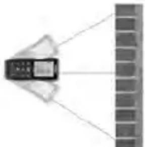
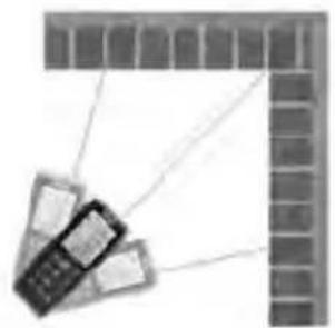
Continuous Measurement, Max and Min Measurement
- Press and Hold ON/Measurement Button ( 12 ) until the laser active symbol ( ) appears permanently on the screen and a beep sounds. Every further press of the button gives a measurement.
- Press and Hold either ON/Measurement Button or Clear/OFF Button (ON/OFF) to stop continuous laser. The laser automatically switches OFF after 3 minutes of inactivity.
- Press the Max-Min Button ( ) until the Max and Min Measurement symbol ( ) appears on screen.
- In continuous measurement mode, the measured value is updated approximately every 0.5 seconds in the third line. The corresponding minimum and maximum values are displayed dynamically in the first and second line.
MIN
natural_image
Diagram showing a device emitting light from a wall to a brick wall (no text or symbols)MAX
natural_image
Illustration of a mobile phone with cables extending from a brick wall (no text or symbols)Figure 7 – Max and Min Measurement
- Press either ON/Measurement Button ( ) or Clear/OFF Button ( ) to stop continuous measurement. The device automatically stops after 100 continuous measurements.
Adding/Subtracting Measurements
- Press Addition Button (+) to add the next measurement to the previous one.
- Press Subtraction Button ( - ) to subtract the next measurement from the previous one.
- Press Clear/OFF Button (=) to cancel the last action.
- Press the Max-Min Button (☐) to return to taking single measurements.
Area Measurement
- Press Area/Volume Button (☐). The symbol (☐) appears in the display.
- Press ON/Measurement Button to take the first measurement (e.g. length).
- Press ON/Measurement Button again to take the second measurement (e.g. width).
- The result of the area calculation is displayed in the summary line.
Volume Measurement
-
Press Area/Volume button (☐) twice until the (☐) symbol appears in the display.
-
Press ON/Measurement Button ( ) to take the first measurement (length).
- Press ON/Measurement Button again to take the second measurement (width).
- Press ON/Measurement Button again to take the third measurement (height).
- The result of the volume calculation is displayed in the summary line.
Indirect Measurements
Indirect measurements are used when a direct measurement is not possible. Indirect measurements are calculated from measurements of the hypotenuse and one side of a right triangle (triangle with a 90 degree angle). For instance, if calculating the height of a wall from the ground, measurements would be taken to the top of the wall (hypotenuse), and perpendicular to the line between the two measurement points at the wall base (side). From these two measurements, the distance between the two measurement points is calculated.
Indirect measurements are less accurate than direct measurements. For greatest accuracy with Indirect Measurements, hold the micro LM-400 in the same position (only changing angle) for all measurements. Make sure that the laser beam is perpendicular to the line between the measurement points when measuring the side of the triangle. All measurements need to be to points on a single straight line.
Using Two Points
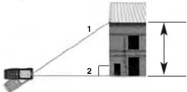
Figure 8 – Indirect Measurement Using Two Points
- Press Indirect Measurement Button (☐) once. The symbol (☐) will show in the display. The distance to be measured will flash in the symbol.
- Press ON/Measurement Button ( ) to turn ON the laser, aim the laser at the upper point (1) and trigger the measurement. The measurement will be displayed in the first line.
- Keeping the instrument as perpendicular to the line between the measurements as possible (with the use of spirit level), Press ON/Measurement Button again to measure the distance result of the horizontal point (2). The measurement will be displayed in the second line.
- The result of the calculation is displayed in summary line.
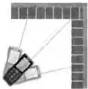
Using Three Points (Total Height)
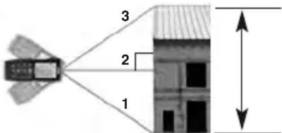
Figure 9 – Indirect Measurement Using Three Points (Total Height)
- Press Indirect Measurement Button (☐) twice, the symbol (☑) will show in the display. The distance to be measured will flash in the symbol.
- Aim the laser at the lower point (1) and press ON/Measurement Button (▲) to take the measurement. The measurement will be displayed in first line.
- Keeping the instrument as perpendicular to the line between the measurements as possible (with the use of spirit level), Press ON/Measurement Button again to measure the distance of the horizontal point (2). The measure will be displayed in the second line.
- Aim the laser at the top point (3), press ON/Measurement Button to take the measurement. The measurement will be displayed in the third line.
- The result of the calculation (Distance 1-3) is displayed in summary line.
Using Three Points (Partial Height)
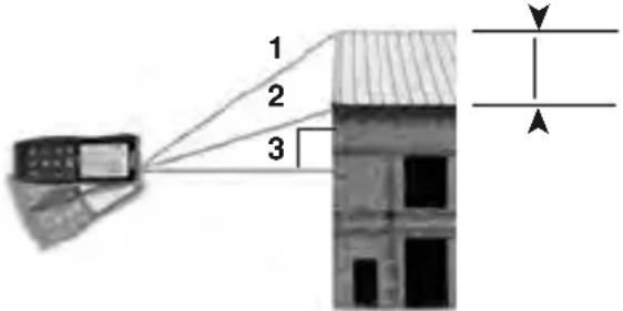
Figure 10 – Indirect Measurement Using Three Points (Partial Height)
- Press Indirect Measurement Button (☐) 3 times, the symbol (☐) will show in the display. The distance to be measured will flash in the symbol.
- Aim the laser at the point (1) and press ON/Measurement Button (▲) to take the measurement. The measurement will be displayed in first line.
- Aim the laser at the point (2), press ON/Measurement Button to take the measurement. The measurement will be displayed in the second line.
- Keeping the instrument as perpendicular to the line between the measurements as possible (with the use of spirit level), Press ON/Measurement Button again to measure the distance of the horizontal point (3). The measurement will be displayed in the third line.
- The result of the calculation (Distance 1-2) is displayed in summary line.
Indirect Measurements With Inclination Sensor
The inclination sensor measures vertical angles between ±65^ allowing 5 indirect distance measurement modes. During angle measurement, the instrument should be held with minimal side to side rotation ( ±10^ from level) to function properly.
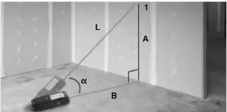
Figure 11 – Indirect Horizontal and Vertical Distance
-
Press Angle/Stake Out Button (☐), the symbol (☐) will show in the display. The distance to be measured will flash in the symbol.
-
Aim the laser at point 1, press ON/Measurement Button to take the measurement.
-
The display shows; measured angle ( ) in the first line, calculated vertical distance A in the second line, calculated horizontal distance B in the third line and the measured diagonal distance L in the fourth line.
Indirect Horizontal Distance
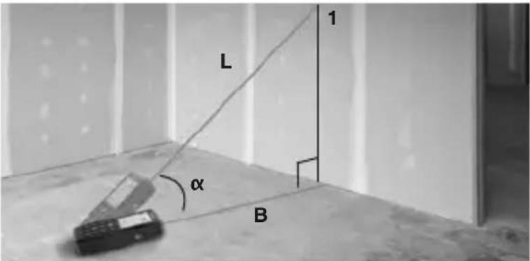
Figure 12 – Indirect Horizontal Distance
-
Press Angle/Stake Out Button (▲) two times, the symbol (∠) will show in the display. The distance to be measured will flash in the symbol.
-
Aim the laser at point 1, press ON/Measurement Button to take the measurement.
-
The display shows; measured angle ( ) in the first line, measured diagonal distance L in the second line, and the calculated horizontal distance B in the fourth line.
Indirect Vertical Distance
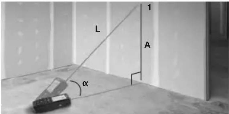
Figure 13 – Indirect Vertical Distance
-
Press Angle/Stake Out Button (☐) three times, the symbol (☐) will show in the display. The distance to be measured will flash in the symbol.
-
Aim the laser at point 1, press ON/Measurement Button to take the measurement.
-
The display shows; measured angle ( ) in the first line, measured diagonal distance L in the second line, and the calculated vertical distance A in the fourth line.
Indirect Vertical Distance Using Two Points (Total Height)
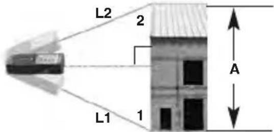
Figure 14 – Indirect Vertical Distance Using Two Points (Total Height)
- Press Angle/Stake Out Button (☐) four times, the symbol (☐) will show in the display. The distance to be measured will flash in the symbol.
- Aim the laser at the first target 1 below the laser distance meter and press ON/Measurement Button to take the measurement.
- Aim the laser at the second target 2 above the laser distance meter and press ON/Measurement Button to take the measurement.
- The display shows; the lower measured diagonal distance L1 in the second line, the upper measured diagonal distance L2 in the third line, and the calculated vertical A distance in the fourth line.
Indirect Vertical Distance Using Two Points (Partial Height)
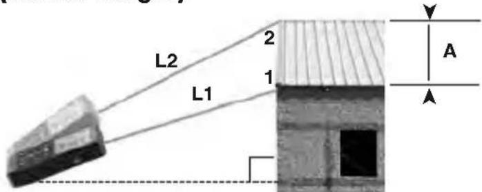
Figure 15 – Indirect Vertical Distance Using Two Points (Partial Height)
- Press Angle/Stake Out Button ( ) five times, the symbol ( ) will show in the display. The distance to be measured will flash in the symbol.
- Aim the laser at the first target 1 and press ON/Measurement Button to take the measurement.
- Aim the laser at the second target 2 and press ON/Measurement Button to take the measurement.
- The display shows; the measured diagonal distance L1 in the second line, the measured diagonal distance L2 in the third line, and the calculated vertical A distance in the fourth line.
Stake Out Measurement
Two different distances (a and b) can be entered into the instrument and can then be used to mark off defined measured lengths, e.g. in the construction of wall studs.
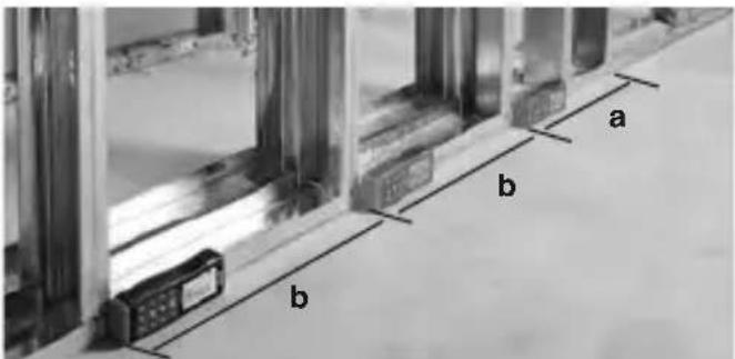
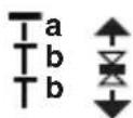
Figure 16 – Stake out Measurement
-
Press the Angle/Stake Out Button (☐) longer and the stake out function symbol (☐) appears in the display. The value (a) and the corresponding intermediate line flash.
-
By using (+) and (-), the value can be adjusted to suit the desired stake out distance. Holding down the buttons increases the rate of change of the values.
-
Once the desired value (a) has been reached, it can be confirmed with the (.) button.
-
The value (b) and the intermediate line flashes. Value (b) can be entered using () and () . The defined value (b) is confirmed with the () button.
-
Pressing the ON/Measurement Button ( ) starts the laser measurement. The display shows current measuring distance in the summary line. Moving slowly along the stake out line the display distance decreases. The instrument starts to beep at a distance of 0.1 m from the next stake out point.
-
The arrows (▲) in the display indicate in which direction the instrument needs to be moved in order to achieve the defined distance (either a or b). As soon as the stake out point is reached the beep changes and the intermediate line starts to flash.
Cleaning
Do not immerse the RIDGID micro LM-400 Laser Distance Meter in water. Wipe off dirt with a damp soft cloth. Do not use aggressive cleaning agents or solvents. Gently clean the display screen with a clean dry cloth. Avoid rubbing too hard. Treat the instrument as you would a telescope or camera.
Storage
The RIDGID micro LM-400 Laser Distance Meter must be stored in a dry secure area between 14^ (-10^) and 140^ (60^) and humidity less than 70% RH.
Store the tool in a locked area out of the reach of children and people unfamiliar with the instrument.
Remove the batteries before any long period of storage or shipping to avoid battery leakage.
The tool should be protected against hard impacts, moisture and humidity, dust and dirt, extreme high and low temperatures and chemical solutions and vapors.
Service and Repair
WARNING
Improper service or repair can make the RIDGID micro LM-400 Laser Distance Meter unsafe to operate.
Service and repair of the micro LM-400 Laser Distance Meter must be performed by a RIDGID Authorized Independent Service Center.
For information on your nearest RIDGID Authorized Independent Service Center or any service or repair questions:
- Contact your local RIDGID distributor.
- Visit RIDGID.com to find your local RIDGID contact point.
- Contact Ridge Tool Technical Service Department at rttechservices@emerson.com, or in the U.S. and Canada call (800) 519-3456.
Disposal
Parts of the RIDGID micro LM-400 Laser Distance Meter contain valuable materials and can be recycled. There are companies that specialize in recycling that may be found locally. Dispose of the components in compliance with all applicable regulations. Contact your local waste management authority for more information.
For EC Countries: Do not dispose of elec trical equipment with household waste!
According to the European Guideline 2012/19/EU for Waste Electrical and Electronic Equipment and its implementation into national legislation, electrical equipment that is no longer usable must be collected separately and disposed of in an environmentally correct manner.
Battery Disposal
For EC countries: Defective or used batteries must be recycled according to the guideline 2012/19/EU.
Troubleshooting - Error Codes
| CODE | CAUSE CORRECTIVE MEASURE | |
| 204 | Calculation error. | Repeat procedure. |
| 208 | Received signal too weak, measurement time too long, Distance >328 ft (100 m). | Use target plate. |
| 209 | Received signal too strong. Target too reflective. | Use a commercially available target plate. |
| 252 | Temperature too high. | Cool down instrument. |
| 253 | Temperature too low. | Warm up instrument. |
| 255 | Hardware error. | Power the unit OFF then ON, if the symbol still appears, please contact technical support. |
micro LM-400
Télémetre laser micro LM-400

AVERTISSEMENT !
natural_image
Diagram showing a mobile phone connected to a brick wall, no text or symbols presentMaxi

natural_image
Illustration of a mobile phone with cables extending into a brick wall (no text or symbols)natural_image
Diagram showing a device emitting light rays from a brick wall (no text or symbols)MÁX
natural_image
Illustration of a mobile phone with attached phones and a brick wall, no text or symbols presentnatural_image
Diagram showing a mobile phone projecting a wall-mounted device (no text or symbols visible)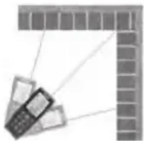
natural_image
Illustration of a mobile phone with cables extending from a grid-patterned wall (no text or symbols)RIDGE TOOL COMPANY Ridge Tool Europe NV (RIDGID)
EC DECLARATION OF CONFORMITY
We declare that the machines listed above, when used in accordance with the operator's manual, meet the relevant requirements of the Directives and Standards listed below.
DÉCLARATION DE CONFORMITÉ CE
DEKLARACJA ZGODNOŚCI WE
RIDGID® tools are warranted to be free of defects in workmanship and material.
How long coverage lasts
This warranty lasts for the lifetime of the RIDGID® tool. Warranty coverage ends when the product becomes unusable for reasons other than defects in workmanship or material.
How you can get service
To obtain the benefit of this warranty, deliver via prepaid transportation the complete product to RIDGE TOOL COMPANY, Elyria, Ohio, or any RIDGID ^© AUTHORIZED INDEPENDENT SERVICE CENTER. Pipe wrenches and other hand tools should be returned to the place of purchase.
What we will do to correct problems
Warranted products will be repaired or replaced, at RIDGE TOOL'S option, and returned at no charge; or, if after three attempts to repair or replace during the warranty period the product is still defective, you can elect to receive a full refund of your purchase price.
What is not covered
Failures due to misuse, abuse or normal wear and tear are not covered by this warranty. RIDGE TOOL shall not be responsible for any incidental or consequential damages.
How local law relates to the warranty
Some states do not allow the exclusion or limitation of incidental or consequential damages, so the above limitation or exclusion may not apply to you. This warranty gives you specific rights, and you may also have other rights, which vary, from state to state, province to province, or country to country.
No other express warranty applies
This FULL LIFETIME WARRANTY is the sole and exclusive warranty for RIDGID ^® products. No employee, agent, dealer, or other person is authorized to alter this warranty or make any other warranty on behalf of the RIDGE TOOL COMPANY.

FULL LIFETIME WARRANTY
Elyria, Ohio 44035-6001
U.S.A.
Ce qui est couverl
- micro LM-400 Laser Distance Meter
- micro LM-400
- WARNING!
- Safety Symbols
- DANGER
- WARNING
- CAUTION
- NOTICE
- General Safety Rules
- SAVE THESE INSTRUCTIONS!
- Work Area Safety
- Electrical Safety
- Personal Safety
- Equipment Use and Care
- Service
- Specific Safety Information
- Laser Distance Meter Safety
- Description, Specifications And Standard Equipment
- Description
- Specifications
- Features
- Standard Equipment
- Controls
- Laser Classification
- FCC Statement
- Electromagnetic Compatibility (EMC)
- Changing/Installing Batteries
- Pre-Operation Inspection
- Do not look into the laser beam. Looking into the laser beam may be hazardous to the eyes.
- Set-Up and Operation
- Do not look into the laser beam. Looking into the laser beam may be hazardous to the eyes. Do not look at the laser beam with optical aids (such as binoculars or telescopes)
- Set up and operate the distance meter according to these procedures to reduce the risk of injury or incorrect measurements.
- micro LM-400 Controls and Settings
- Turning ON and OFF
- Changing Display Units
- Setting Measurement Reference Point
- Clearing Displayed Data/Last Action
- Reviewing the Last 20 Measurements
- Clearing Data from Memory
- Backlighting the Display
- Timer (Self-Triggering)
- Wireless Data Transfer
- Measurements
- Single Distance Measurement
- Continuous Measurement, Max and Min Measurement
- Adding/Subtracting Measurements
- Area Measurement
- Volume Measurement
- Indirect Measurements
- Indirect Measurements With Inclination Sensor
- Indirect Horizontal Distance
- Indirect Vertical Distance
- Indirect Vertical Distance Using Two Points (Total Height)
- Indirect Vertical Distance Using Two Points (Partial Height)
- Stake Out Measurement
- Cleaning
- Storage
- Service and Repair
- Disposal
- Battery Disposal
- Télémetre laser micro LM-400
- AVERTISSEMENT !
- EC DECLARATION OF CONFORMITY
- DÉCLARATION DE CONFORMITÉ CE
- DEKLARACJA ZGODNOŚCI WE
- How long coverage lasts
- How you can get service
- What we will do to correct problems
- What is not covered
- How local law relates to the warranty
- No other express warranty applies
- Ce qui est couverl
Brand : RIDGID
Model : Micro LM400
Category : Measuring equipment