
Micro LM100 - Measuring equipment RIDGID - Free user manual and instructions
Find the device manual for free Micro LM100 RIDGID in PDF.
| Product Type | Laser Distance Measurer |
| Brand | RIDGID |
| Model | Micro LM-100 |
| Range | 0.05 to 100 m (0.16 to 328 ft) |
| Accuracy (up to 10 m) | Typically ±1.5 mm (±0.06 in) |
| Measurement Units | m, inches, feet |
| Laser Class | Class II |
| Laser Type | 635 nm, < 1 mW |
| Protection Class | IP54 (dust and splash) |
| Memory | 20 measurements |
| Operating Temperature | 0°C to 40°C (32°F to 104°F) |
| Storage Temperature | -10°C to 60°C (14°F to 140°F) |
| Battery Life | Up to 4,000 measurements |
| Battery Type | 2 AAA batteries (LR03) |
| Auto Laser Off | After 30 seconds |
| Auto Power Off | After 3 minutes of inactivity |
| Dimensions (L x W x H) | 115 x 48 x 28 mm |
| Weight | 200 g (7 oz) |
| Main Functions | Single, continuous, min/max, addition/subtraction, area, volume, indirect measurement (2 and 3 points) |
| Backlight | Yes, switchable |
| Beep | Yes |
| Cleaning | Soft damp cloth, do not immerse |
| Warranty | Lifetime (Full Lifetime Warranty) |
Frequently Asked Questions - Micro LM100 RIDGID
User questions about Micro LM100 RIDGID
0 question about this device. Answer the ones you know or ask your own.
Ask a new question about this device
Download the instructions for your Measuring equipment in PDF format for free! Find your manual Micro LM100 - RIDGID and take your electronic device back in hand. On this page are published all the documents necessary for the use of your device. Micro LM100 by RIDGID.
USER MANUAL Micro LM100 RIDGID
Read this Operator's Manual carefully before using this tool. Failure to understand and follow the contents of this manual may result in electrical shock, fire and/or serious personal injury.
- Français – 13
Recording Form for Machine Serial Number ....1
Safety Symbols....2
General Safety Rules
Work Area Safety....3
Electrical Safety....3
Personal Safety....3
Equipment Use and Care 3
Service....4
Specific Safety Information
Laser Distance Meter Safety 4
Description, Specifications and Standard Equipment
Description....4
Specifications 4
Controls 5
LCD Display Icons 6
Standard Equipment....6
Laser Classification 6
FCC Statement......6
Electromagnetic Compatibility (EMC) 7
Installing Wrist Strap....7
Changing/Installing Batteries....7
Pre-Operation Inspection....7
Set-Up and Operation 8
LM-100 Controls and Settings
Turning ON and OFF 8
Setting Measurement Reference Point 8
Changing Display Units 8
Clearing Displayed Detail/Last Action....8
Reviewing The Last 20 Measurements....8
Clearing Data From Memory 9
Backlighting The Display....9
Measurements
Single Distance Measurement....9
Continuous Measurement, Max. and Min. Measurement .....9
Adding/Subtracting Measurements....9
Area Measurement 9
Volume Measurement....10
Indirect Measurements
Using Two Points....10
Using Three Points....11
Cleaning....11
Storage 11
Service and Repair ....11
Disposal 12
Troubleshooting 12
EC Declaration of Conformity ......Inside Back Cover
Lifetime Warranty ....Back Cover
*Original Instructions - English
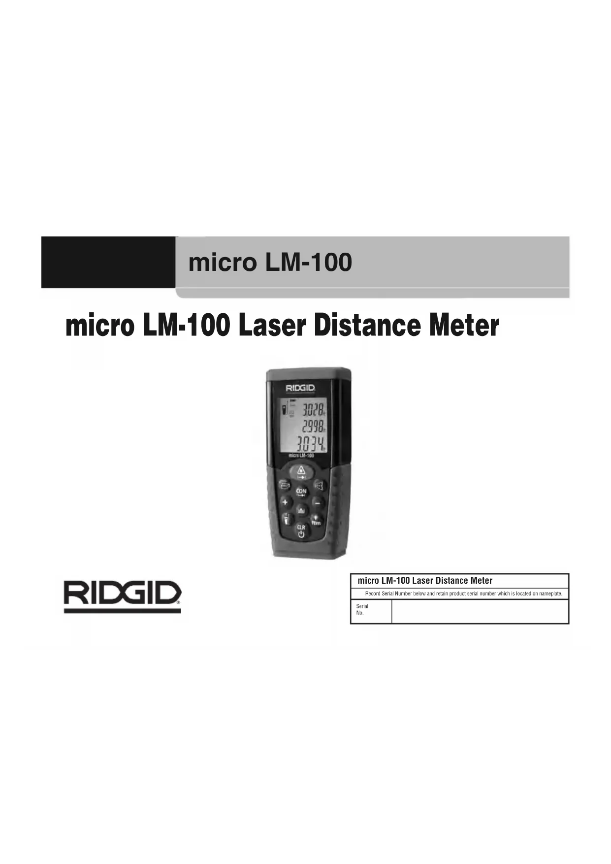
micro LM-100
micro LM-100 Laser Distance Meter

RIDGID
| micro LM-100 Laser Distance Meter | |
| Record Serial Number below and retain product serial number which is located on nameplate. | |
| SerialNo. | |
Safety Symbols
In this operator's manual and on the product, safety symbols and signal words are used to communicate important safety information. This section is provided to improve understanding of these signal words and symbols.

This is the safety alert symbol. It is used to alert you to potential personal injury hazards. Obey all safety messages that follow this symbol to avoid possible injury or death.

DANGER DANGER indicates a hazardous situation which, if not avoided, will result in death or serious injury.

WARNING indicates a hazardous situation which, if not avoided, could result in death or serious injury.

CAUTION indicates a hazardous situation which, if not avoided, could result in minor or moderate injury.

ICE NOTICE indicates information that relates to the protection of property.

This symbol means read the operator's manual carefully before using the equipment. The operator's manual contains important information on the safe and proper operation of the equipment.

This symbol means this device contains a Class 2 Laser.

This symbol means do not stare into the laser beam.

This symbol warns of the presence and hazard of a laser beam.
General Safety Rules
WARNING
Read all safety warnings and in struc tions. Failure to follow the warn ings and instructions may result in electric shock, fire and/or serious injury.
SAVE THESE INSTRUCTIONS!
Work Area Safety
- Keep your work area clean and well lit. Cluttered or dark areas invite accidents.
- Do not operate equipment in explosive atmospheres, such as in the presence of flammable liquids, gases, or dust. Equip ment can create sparks which may ignite the dust or fumes
- Keep children and by-standers a way while operating equipment. Distrac tions can cause you to lose control.
Electrical Safety
- Avoid body contact with earthed or grounded surfaces such as pipes, radiators, ranges and refrigerators. There is an increased risk of electrical shock if your body is earthed or grounded.
- Do not expose equipment to rain or wet conditions. Water en tering equipment will increase the risk of electrical shock.
Personal Safety
- Stay alert, watch what you are doing and use common sense when operating equipment. Do not use equipment while you are tired or under the influence of drugs, alcohol or medication. A moment of inattention while operating equipment may result in serious personal injury.
- Use personal protective equipment. Always wear eye protection. Protective equipment such as dust mask, non-skid safety
shoes, hard hat, or hearing protection used for appropriate conditions will reduce personal injuries.
- Do not overreach. Keep proper footing and balance at all times. This enables better control of the power tool in unexpected situations.
Equipment Use and Care
- Do not force equipment. Use the correct equipment for your application. The correct equipment will do the job better and safer at the rate for which it is designed
- Do not use equipment if the switch does not turn it ON and OFF. Any tool that cannot be controlled with the switch is dangerous and must be repaired.
- Disconnect the batteries from the equipment before making any adjustments, changing accessories, or storing. Such preventive safety measures reduce the risk of injury.
- Store idle equipment out of the reach of children and do not allow persons unfamiliar with the equipment or these instructions to operate the equipment. Equipment can be dangerous in the hands of untrained users.
- Maintain equipment. Check for misalignment or binding of moving parts, missing parts, breakage of parts and any other condition that may affect the equipment's operation. If damaged, have the equipment repaired before use. Many accidents are caused by poorly maintained equipment
- Use the equipment and accessories in accordance with these instructions, taking into account the working conditions and the work to be performed. Use of the equipment for operations different from those intended could result in a hazardous situation
- Use only accessories that are recommended by the manufacturer for your equipment. Accessories that may be suitable

micro LM-100 Laser Distance Meter
for one piece of equipment may become hazardous when used with other equipment
- Keep handles dry and clean; free from oil and grease. Allows for better control of the equipment.
Service
- Have your equipment serviced by a qualified repair person using on ly identical replacement parts. This will ensure that the safety of the tool is maintained.
Specific Safety Information
WARNING
This section contains important safety information that is specific to this tool.
Read these precautions carefully before using the micro LM-100 Laser Distance Meter to reduce the risk of eye injury or other serious personal injury.
SAVE THESE INSTRUCTIONS!
Keep this manual with the tool for use by the operator.
Laser Distance Meter Safety
- Do not look into the laser beam. Looking into the laser beam may be hazardous to the eyes. Do not look at the laser beam with optical aids (such as binoculars or telescopes).
- Do not direct the laser beam towards other people. Make sure the laser is aimed above or below eye level. Laser beams may be hazardous to the eyes.
⚠️ CAUTION Use of controls or adjustments or performance of procedures other than those specified herein may result in hazardous radiation exposure.
If you have any question concerning this RIDGID product:
- Contact your local RIDGID distributor.
- Visit RIDGID.com to find your local RIDGID contact point.
- Contact Ridge Tool Technical Services Department at rtctechservices@emerson.com, or in the U.S. and Canada call (800) 519-3456.
Description, Specifications And Standard Equipment
Description
The RIDGID® micro LM-100 provides simple, quick, and accurate distance readings at the push of a button. You simply push the measurement button to turn on the class II laser and point at the remote or difficult to reach place to be measured to, then push the measurement button again. The micro LM-100 provides a quick measurement on a clear easy to read backlit LCD display.
Specifications
Range ....0.05 to 100m ^ (0.16 ft to 328 ft ^ )
Measuring Accuracy Up To 10m (2, Standard Deviation) ....Typically: ±1.5mm ^ (± 0.06 in ^ )
Measuring Units....m, in, ft Laser Class....Class II Laser Type ....635 nm, <1 mW Ingress Protection ....IP 54 Dust Proof, Splash Proof Memory....20 Measurements Operating Temperature ....0°C to 40°C (32°F to 104°F) Storage Temperature ....-10°C to 60°C (14°F to 140°F)
Battery Life.....Up to 4,000 Measurements
Batteries....(2) AAA
Auto. Laser Switch-Off ......After 30 Seconds
Auto. Shut-Off.....After 3 Minutes of Inactivity
Dimension 115 x 48 x 28mm
$$ (4 ^ {1 / 2} \times 1 ^ {7 / 8} \times 1 ^ {1 / 8}) $$
Weight....0.2kg (7oz)
Features
• Area, Volume Calculations
• Continuous Measurement
- Indirect Measurement
• Min/Max Distance Tracking
- Addition/Subtraction
- Beep Indication
• Display Illumination and Multi-line Display
* Range is limited to 100 m (328 ft.) Use a commercially available target plate to improve measurement ability during daylight or if the target has poor reflection properties.
**In favorable conditions (good target surface properties, room temperature) up to 10m (33 ft). In unfavorable conditions, such as intense sunshine, poorly reflecting target surface or high temperature variations, the deviation over distances above 10m (33 ft) can increase by ±0.15mm/m (±0.0018 in/ft).

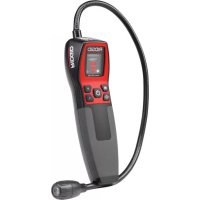
natural_image
Product photo of a handheld electronic device with a black strap and two flashlights (no visible text or symbols)Figure 1 – micro LM-100 Laser Distance Meter
Controls

Figure 2 – micro LM-100 Buttons
LCD Display Icons

Figure 3 – micro LM-100 LCD Display
Standard Equipment
- micro LM-100
- Carrying Case
-
Wrist Strap
-
Batteries (2 AAA)
- Operator's Manual
NOTICE This equipment is used to make distance measurements. Incorrect use or improper application may result in incorrect or inaccurate measurements. Selection of appropriate measurement methods for the conditions is the responsibility of the user.
Laser Classification

The RIDGID micro LM-100 generates a visible laser beam that is emitted from the top of the device.
The device complies with class 2 lasers according to: IEC 60825-1:2007
FCC Statement
This equipment has been tested and found to comply with the limits for a Class B digital device, pursuant to part 15 of the FCC Rules. These limits are designed to provide reasonable protection against harmful interference in a residential installation.
This equipment generates, uses, and can radiate radio frequency energy and, if not installed and used in accordance with the instructions, may cause harmful interference to radio communications.
However, there is no guarantee that interference will not occur in a particular installation.
If this equipment does cause harmful interference to radio or television reception, which can be determined by turning the equipment off and on, the user is encouraged to try to correct the interference by one or more of the following measures:
- Reorient or relocate the receiving antenna.
- Increase the separation between the equipment and receiver.
- Consult the dealer or an experienced radio/TV technician for help.
Electromagnetic Compatibility (EMC)
The term electromagnetic compatibility is taken to mean the capability of the product to function smoothly in an environment where electromagnetic radiation and electrostatic discharges are present and without causing electromagnet interference to other equipment.
NOTICE The RIDGID micro LM-100 conforms to all applicable ECM standards. However, the possibility of it causing interference in other devices cannot be precluded.
Installing Wrist Strap
Route small end of wrist strap through loop on micro LM-100 housing. Thread strap end through loop of small end and pull tight.

natural_image
Close-up of hands using a tool to adjust or install electronic components on a black electronic device (no visible text or symbols)Figure 4 – Installing Lanyard

natural_image
Black electronic device with two batteries and a partially open casing (no visible text or symbols)Figure 5 – Changing Batteries
Changing/Installing Batteries
The micro LM-100 is supplied with batteries installed. If the battery indicator is flashing, the batteries need to be replaced. Remove the batteries prior to long term storage to avoid battery leakage. (Figure 5)
-
Use a Phillips head screw driver to loosen the battery compartment cover screw and remove the cover.
-
Remove existing batteries.
- Install two AAA alkaline batteries (LR03), observing the correct polarity as indicated in the battery compartment.
NOTICE Use batteries that are of the same type. Do not mix battery types. Do not mix new and used batteries. Mixing batteries can cause overheating and battery damage. - Replace cover and tighten screw.
Pre-Operation Inspection
WARNING
Before each use, inspect your distance meter and correct any problems to reduce the risk of injury or incorrect measurements.
Do not look into the laser beam. Looking into the laser beam may be hazardous to the eyes.
- Clean any oil, grease or dirt from equipment. This aids inspection.
- Inspect the distance meter for any broken, worn, missing, mis-aligned or binding parts, or any other condition which may prevent safe and normal operation.
- Check that the warning labels are present, firmly attached and readable. (See Figure 6.)
- If any issues are found during the inspection, do not use the distance meter until it has been properly serviced.
Following the Operation Instructions, turn the distance meter on, make a measurement and confirm the same measurement with another instrument (tape measure, etc.). If the correlation be tween the measurements is not acceptable, do not use the distance meter until it has been properly serviced.

Figure 6 – Warning Labels

Set-Up and Operation
WARNING


Do not look into the laser beam. Looking into the laser beam may be hazardous to the eyes. Do not look at the laser beam with optical aids (such as binoculars or telescopes).
Do not direct the laser beam towards other people. Make sure the laser is aimed above or below eye level. Laser beams may be hazardous to the eyes.
Set up and operate the distance meter according to these procedures to reduce the risk of injury or incorrect measurements.
- Check for an appropriate work area as indicated in the General Safety Section.
- Inspect the object being measured to and confirm that you have correct equipment for the application. The micro LM-100 Laser Distance Meter is designed to measure distances up to 100 m
(328 feet). See the Specifications section for range, accuracy and other information.
- Make sure that all equipment has been properly inspected.
micro LM-100 Controls and Settings
Turning ON and OFF
Press the ON/Measurement Button 🙏 to turn ON the distance meter and the laser. Make sure that the laser is pointed in a safe direction before turning ON.
Press and Hold the Clear/Power OFF Button to turn the Distance meter OFF. The laser distance meter will turn OFF automatically after three minutes of inactivity.
Setting Measurement Reference Point
When the distance meter is turned ON, the default measurement reference point is the back edge of the meter. Press the Measurement Reference Point Button to change the measurement reference point to the front edge (laser end) of the meter. The meter will beep and the display will show the reference point front symbol.
Changing Display Units
Press and Hold the Backlight/Unit Change Button to change the display units. Available Units: Feet, Meters, Inches.
Clearing Displayed Data/Last Action
Press the Clear/Power OFF Button to clear the displayed data or cancel the last action.
Reviewing the Last 20 Measurements
Press the Memory Button to review the last twenty measure-
ments or calculated results, shown in reverse order. Use the Addition or Subtraction Buttons + - to move through these records.
Clearing Data From Memory
Press and Hold the Memory Button and Press and Hold the Clear/Power Button Key at the same time to clear all data in the memory.
Backlighting the Display
Press the Backlight/Unit Change Button to turn the display backlight ON or OFF.
Measurements
The RIDGID micro LM-100 Laser Distance Meter has a measuring range of 100 m (328') maximum. Use in bright sunlight may decrease the range of the meter. The reflective properties of the surface may also decrease the range of the meter.
Measurement errors can occur when measuring to clear, semi-permeable or high gloss/reflective surfaces such as colorless liquids (e.g. water), glass, Styrofoam, mirrors, etc. Applying a commercially available laser target plate to the surface may allow more accurate measurements.
NOTICE Do not aim the laser at the sun. This can damage the meter.
Single Distance Measurement
- Press ON/Measurement Button 🙏 to activate the laser. Press ON/Measurement Button 🚫 again to take a measurement.
- The measured value is displayed immediately.
Continuous Measurement, Max and Min Measurement
- Press and Hold Continuous Measurement Button CON to enter the continuous measurement mode. In continuous measurement mode, the measured value is updated approximately every 0.5 seconds in the third line. The corresponding minimum and maximum values are displayed dynamically in the first and second line.
- Press and Hold either ON/Measurement Button or Clear/-Power OFF Button to stop taking continuous measurements. The device automatically stops after 100 continuous measurements.
Adding/Subtracting Measurements
- Press Addition Button to add the next measurement to the previous one.
- Press Subtraction Button to subtract the next measurement the previous one.
- Press Clear/Power OFF Button ☑ to cancel the last action.
- Press Clear/Power OFF Button 📄 again to return to taking single measurements.
Area Measurement
- Press Area/Volume Button ^2 . The symbol appears in the display. The distance to be measured will flash in the symbol.
- Press ON/Measurement Button 🙏 to take the first measurement (e.g. length).
- Press ON/Measurement Button 🙏 again to take the second measurement (e.g. width).
- The result of the area calculation is displayed in the third line; the individually measured values are displayed in lines 1 and 2.
Volume Measurement
- Press Area/Volume button ☐. The symbol appears in the display. The distance to be measured will flash in the symbol.
- Press Area/Volume button again, the symbol for volume measurement appears in the display. The distance to be measured will flash in the symbol
- Press ON/Measurement Button to take the first measurement (e.g. length).
- Press ON/Measurement Button 🙏 again, to take the second measurement (e.g. width).
- The result of the area calculation is displayed in the third line; the individually measured values are displayed in lines 1 and 2.
- Press ON/Measurement Button again, take the third distance measurement (e.g. height). The value is displayed in the second line.
The result of the volume calculation is displayed in the third line.
Indirect Measurements
Indirect measurements are used when a direct measurement is not possible. Indirect measurements are calculated from measurements of the hypotenuse and one side of a right triangle (triangle with a 90 degree angle). For instance, if calculating the height of a wall from the ground, measurements would be taken to the top of the wall (hypo-tenuse), and perpendicular to the line between the two measurement points at the wall base (side). From these two measurements, the distance between the two measurement points is calculated.
Indirect measurements are less accurate than direct measurements. For greatest accuracy with Indirect Measurements, hold the micro LM-100 in the same position (only changing angle) for all measurements. Make sure that the laser beam is perpendicular to the line between the measurement points when measuring the side of the
triangle. All measurements need to be to points on a single straight line.
Using Two Points

Figure 7 – Indirect Measurement Using Two Points
- Press Indirect Measurement Button once. The symbol will show in the display. The distance to be measured will flash in the symbol.
- Press ON/Measurement Button 📄 to turn ON the laser, aim the laser at the upper point (1) and trigger the measurement. The measurement will be displayed in the first line.
- The next distance to be measured will flash.
- Press ON/Measurement Button 🙏 to turn on the laser, keeping the instrument as perpendicular to the line between the measurements as possible, Press ON/Mea surement Button 🙏 again to measure the distance result of the horizontal point (2). The measurement will be displayed in the second line.
- The result of the calculation is displayed in third line.
Using Three Points

Figure 8 – Indirect Measurement Using Three Points
- Press Indirect Measurement Button ⏻ once, the △ symbol will show in the display. The distance to be measured will flash in the symbol.
- Press Indirect Measurement Button 📍 again, the symbol will show in the display. The distance to be measured will flash in the symbol.
- Aim the laser at the lower point (1) and press button 1 to take the measurement. The measurement will be displayed in first line.
- The next distance to be measured will flash.
- Press ON/Measurement Button 📁 to turn on the laser, keeping the instrument as perpendicular to the line between the measurements as possible, Press ON/Mea surement Button 📁 again to measure the distance result of the horizontal point (2). The measurement will be displayed in the second line.
- Press ON/Measurement Button 📄 to turn on the laser, aim the laser at the top point, press ON/Measurement Button 📄
to take the measurement. The measurement will be displayed in the second line.
- The result of the calculation is displayed in third line.
Cleaning
Do not immerse the RIDGID micro LM-100 in water. Wipe off dirt with a damp soft cloth. Do not use aggressive cleaning agents or solutions. Treat the instrument as you would a telescope or camera.
Storage
The RIDGID micro LM-100 laser distance meter must be stored in a dry secure area between -10^ ( 14^ ) and 60^ ( 158^ ).
Store the tool in a locked area out of the reach of children and people unfamiliar with the laser distance meter.
Remove the batteries before any long period of storage or shipping to avoid battery leakage.
Service and Repair
WARNING
Improper service or repair can make the RIDGID micro LM-100 unsafe to operate.
Service and repair of the RIDGID micro LM-100 must be performed by a RIDGID Authorized Independent Service Center.
For information on your nearest RIDGID Authorized Independent Service Center or any service or repair questions:
- Contact your local RIDGID distributor.
- Visit RIDGID.com to find your local Ridge Tool contact point.
- Contact Ridge Tool Technical Services Department at rtctechservices@emerson.com, or in the U.S. and Canada call (800) 519-3456.

micro LM-100 Laser Distance Meter
For troubleshooting suggestions, please refer to the Troubleshooting.
Disposal
Parts of the micro LM-100 Laser Distance Meter contain valuable materials and can be recycled. There are companies that specialize in recycling that may be found locally. Dispose of the components in compliance with all applicable regulations. Contact your local waste management authority for more information.

For EC Countries: Do not dispose of elec trical equipment with household waste!
According to the European Guideline 2012/19/EU for Waste Electrical and Electronic Equipment and its implementation into national legislation, electrical equipment
that is no longer usable must be collected separately and disposed of in an environmentally correct manner.
Battery Disposal
For EC countries: Defective or used batteries must be recycled according to the guideline 2012/19/EU.
Troubleshooting - Error Codes
| CODE CAUSE CORRECTIVE MEASURE | ||
| 204 | Calculation error. | Repeat procedure. |
| 208 | Received signal too weak, measurement time too long, Distance >100 m. | Use target plate. |
| 209 | Received signal too strong. Target too reflective. | Use a commercially available target plate. |
| 252 | Temperature too high. | Cool down instrument. |
| 253 | Temperature too low. | Warm up instrument. |
| 255 | Hardware error. | Power the unit OFF then ON, if the symbol still appears, please contact technical support. |
micro LM-100
Télémetre laser micro LM-100


AVERTISSEMENT
Activation/désactivation 22
CONSERVEZ CES INSTRUCTIONS!
Sécurité des lieux
▲ AVIS IMPORTANT Use of controls or adjustments or performance of procedures other than those specified herein may result in hazardous radiation exposure.
natural_image
Product photo of a RIOG device with attached case and two batteries (no visible text or symbols)Figure 1 – Télémètre laser micro LM-100
Commandes

natural_image
Close-up of hands using a tool to adjust or install electronic components (no visible text or symbols)
natural_image
Black electronic device with two batteries and a partially open casing (no visible text or symbols)Figure 4 – Montage du bracelet
Figure 5 – Remplacement des piles
Activation/désactivation
natural_image
Product photo of a RIO3D handheld device with attached black case and two battery sensors (no visible text or symbols)natural_image
Close-up of hands using a battery to switch and disassembled batteries into a black case (no visible text or symbols)Preparativos
ADVERTENCIA


natural_image
Product photo of a PICGID medical device with a handheld device and two flashlights (no visible text or symbols)natural_image
Close-up of hands using a tool to adjust or install electronic components (no visible text or symbols)natural_image
Black rectangular battery pack with three additional batteries and a separate connector (no visible text or symbols)RIDGE TOOL COMPANY Ridge Tool Europe NV (RIDGID)
EC DECLARATION OF CONFORMITY
DÉCLARATION DE CONFORMITÉ CE
DEKLARACJA ZGODNOŚCI WE
Qualification: V.P. Engineering
Date: 10/01/2020
What is covered
RIDGID®tools are warranted to be free of defects in workmanship and material.
How long coverage lasts
This warranty lasts for the lifetime of the RIDGID ^® tool. Warranty coverage ends when the product becomes unusable for reasons other than defects in workmanship or material.
How you can get service
To obtain the benefit of this warranty, deliver via prepaid transportation the complete product to RIDGE TOOL COMPANY, Elyria, Ohio, or any RIDGID® AUTHORIZED INDEPENDENT SERVICE CENTER. Pipe wrenches and other hand to ols should be returned to the place of purchase.
What we will do to correct problems
Warranted products will be repaired or replaced, at RIDGE TOOL'S option, and returned at no charge; or, if after three attempts to repair or replace during the warranty period the product is still defective, you can elect to receive a full refund of your purchase price.
What is not covered
Failures due to misuse, abuse or normal wear and tear are not covered by this warranty. RIDGE TOOL shall not be responsible for any incidental or consequential damages.
How local law relates to the warranty
Some states do not allow the exclusion or limitation of incidental or consequential damages, so the above limitation or exclusion may not apply to you. This warranty gives you specific rights, and you may also have other rights, which vary, from state to state, province to province, or country to country.
No other express warranty applies
This FULL LIFETIME WARRANTY is the sole and exclusive warranty for RIDGID ^® products. No employee, agent, dealer, or other person is authorized to alter this warranty or make any other warranty on behalf of the RIDGE TOOL COMPANY.
Ridge Tool Company
400 Clark Street • Elyria, Ohio 44035-6001
Printed 11/20 999-998-391.10
EC45131 REV. D
©2011, 2020 Ridge Tool Company. All rights reserved.
RIDGID and the Emerson logo are registered trademarks of Emerson Electric Co. or its subsidiaries in the US and other countries.
All other trademarks belong to their respective holders.
RIDGID

EMERSON
- General Safety Rules
- Specific Safety Information
- Description, Specifications and Standard Equipment
- LM-100 Controls and Settings
- Measurements
- Indirect Measurements
- micro LM-100
- micro LM-100 Laser Distance Meter
- Safety Symbols
- WARNING
- SAVE THESE INSTRUCTIONS!
- Work Area Safety
- Electrical Safety
- Personal Safety
- Equipment Use and Care
- Service
- Laser Distance Meter Safety
- Description
- Specifications
- Features
- Standard Equipment
- Laser Classification
- FCC Statement
- Electromagnetic Compatibility (EMC)
- Installing Wrist Strap
- Changing/Installing Batteries
- Pre-Operation Inspection
- Set-Up and Operation
- micro LM-100 Controls and Settings
- Turning ON and OFF
- Setting Measurement Reference Point
- Changing Display Units
- Clearing Displayed Data/Last Action
- Reviewing the Last 20 Measurements
- Clearing Data From Memory
- Backlighting the Display
- Single Distance Measurement
- Continuous Measurement, Max and Min Measurement
- Adding/Subtracting Measurements
- Area Measurement
- Volume Measurement
- Cleaning
- Storage
- Service and Repair
- Improper service or repair can make the RIDGID micro LM-100 unsafe to operate.
- Disposal
- Battery Disposal
- Télémetre laser micro LM-100
- AVERTISSEMENT
- CONSERVEZ CES INSTRUCTIONS!
- Sécurité des lieux
- Activation/désactivation
- Preparativos
- ADVERTENCIA
- EC DECLARATION OF CONFORMITY
- DÉCLARATION DE CONFORMITÉ CE
- DEKLARACJA ZGODNOŚCI WE
- What is covered
- How long coverage lasts
- How you can get service
- What we will do to correct problems
- What is not covered
- How local law relates to the warranty
- No other express warranty applies
- Ridge Tool Company
Brand : RIDGID
Model : Micro LM100
Category : Measuring equipment