ThermoMaster - Thermometer Laserliner - Free user manual and instructions
Find the device manual for free ThermoMaster Laserliner in PDF.
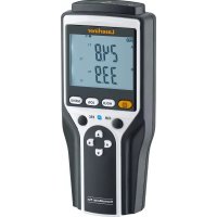
| Product type | Digital thermometer |
| Brand | Laserliner |
| Model | ThermoMaster |
| Display | 3½-digit LCD screen (max. 1999) |
| Measurement range | -50 °C to 1300 °C |
| System accuracy (0 to 1000 °C) | ±(0.5 % of reading + 1 °C) |
| Resolution | 0.1 °C / 1 °C switchable |
| Measurement units | °C / °F switchable |
| Probe inputs | 2 type K inputs (T1 and T2) |
| Functions | T1, T2 measurement, T1-T2 differential, MAX, HOLD, backlight, switchable resolution |
| Power supply | 1 9 V battery (NEDA 1604, IEC 6F22) |
| Dimensions (L x W x H) | 162 mm x 76 mm x 38.5 mm |
| Weight (without battery) | 0.21 kg |
| Operating temperature | 0 °C to 50 °C |
| Storage temperature | -20 °C to 60 °C, 10 % to 70 % RH (non-condensing) |
| Tripod connection | 1/4 inch |
| Protection class | II (reinforced or double insulation) |
| Safety | Do not touch probe tips during measurement; max. 24 V AC / 60 V DC on inputs; avoid strong electromagnetic fields. |
| Maintenance | Regular check; calibration recommended every year; clean with a dry cloth. |
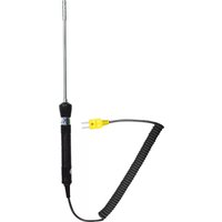
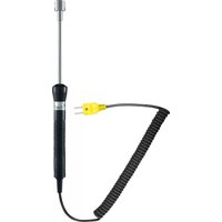
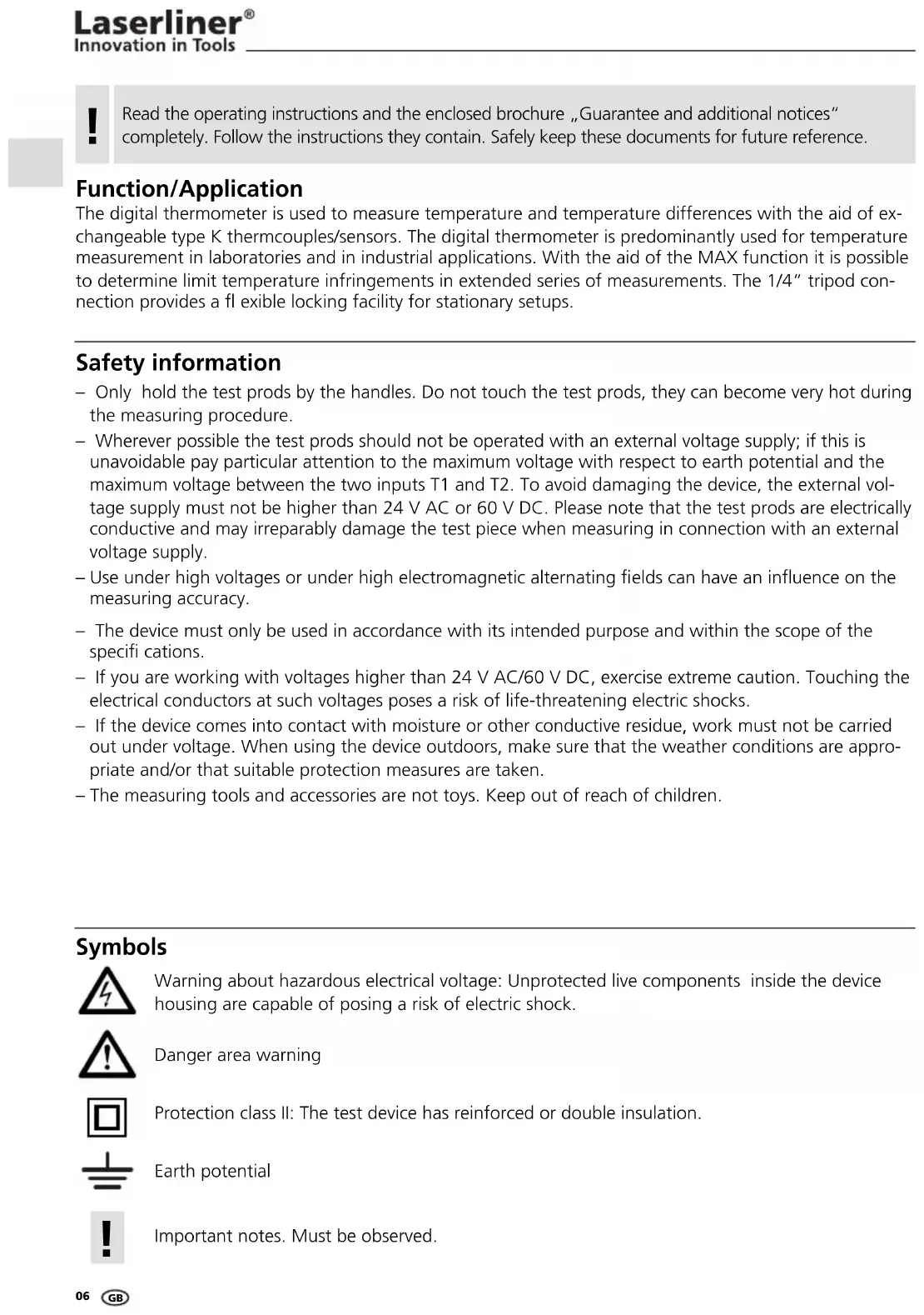
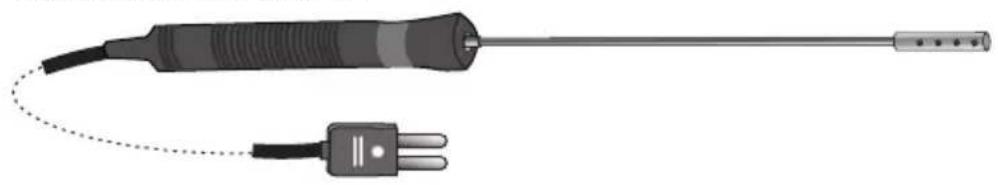
| Included accessories | Removable type K probes (ThermoProbe K, ThermoSensor Air, ThermoSensor Tip) |
| Intended use | Laboratories and industrial applications, temperature and temperature difference measurement. |
| Warranty / Compliance | Compliant with EU standards; disposal according to WEEE directive. |
Frequently Asked Questions - ThermoMaster Laserliner
User questions about ThermoMaster Laserliner
0 question about this device. Answer the ones you know or ask your own.
Ask a new question about this device
Download the instructions for your Thermometer in PDF format for free! Find your manual ThermoMaster - Laserliner and take your electronic device back in hand. On this page are published all the documents necessary for the use of your device. ThermoMaster by Laserliner.
USER MANUAL ThermoMaster Laserliner
text_image
Laserliner® ThermoMaster 120°C T1 T1-T2 T2 MAX HOLD S.1"V1" F °C T1 T1-T2ThermoSensor Air / 082.035.1
natural_image
Illustration of a handheld probe with a dotted line connecting its tip and two terminal pins (no text or symbols)ThermoSensor Tip / 082.035.2
natural_image
Illustration of a probe with a wire and its terminal connector (no text or symbols)Laserliner®
Innovation in Tools
natural_image
Illustration of a mechanical component with a curved arrow indicating rotation (no text or symbols)
text_image
2. θ 3.
text_image
4. 96V1 x 9V Typ (NEDA 1604, IEC 6F22)
text_image
Diagram showing two thermocouple sensors connected to a digital display with labeled ports and an upward arrow indicating measurement or signal flow.!
natural_image
Industrial machine setup with digital display and mechanical components (no visible text or symbols)Read the operating instructions and the enclosed brochure „Guarantee and additional notices“ completely. Follow the instructions they contain. Safely keep these documents for future reference.
Function/Application
The digital thermometer is used to measure temperature and temperature differences with the aid of exchangeable type K thermcouples/sensors. The digital thermometer is predominantly used for temperature measurement in laboratories and in industrial applications. With the aid of the MAX function it is possible to determine limit temperature infringements in extended series of measurements. The 1/4" tripod connection provides a fl exible locking facility for stationary setups.
Safety information
- Only hold the test prods by the handles. Do not touch the test prods, they can become very hot during the measuring procedure.
- Wherever possible the test prods should not be operated with an external voltage supply; if this is unavoidable pay particular attention to the maximum voltage with respect to earth potential and the maximum voltage between the two inputs T1 and T2. To avoid damaging the device, the external voltage supply must not be higher than 24 V AC or 60 V DC. Please note that the test prods are electrically conductive and may irreparably damage the test piece when measuring in connection with an external voltage supply.
- Use under high voltages or under high electromagnetic alternating fields can have an influence on the measuring accuracy.
- The device must only be used in accordance with its intended purpose and within the scope of the specifications.
- If you are working with voltages higher than 24 V AC/60 V DC, exercise extreme caution. Touching the electrical conductors at such voltages poses a risk of life-threatening electric shocks.
- If the device comes into contact with moisture or other conductive residue, work must not be carried out under voltage. When using the device outdoors, make sure that the weather conditions are appropriate and/or that suitable protection measures are taken.
– The measuring tools and accessories are not toys. Keep out of reach of children.
Symbols
Warning about hazardous electrical voltage: Unprotected live components inside the device housing are capable of posing a risk of electric shock.
Danger area warning
Protection class II: The test device has reinforced or double insulation.
Earth potential

Important notes. Must be observed.
General information
- If the thermometer is subject to large fluctuations in the ambient temperature, after the temperature has stabilised, wait 20 minutes before performing a measurement.
- Always ensure adequate thermal coupling at the measuring point in order to avoid measuring errors caused by temperature loss.
- Please note that all thermometers with a contact sensor influence the measurement and their thermal capacity can reduce the actual temperature. More thermal energy should therefore be applied to the thermocouple than it can dissipate.
- OL is shown in the display when no measuring sensor is connected.
- The thermometer shows OL when the measured temperature is outside the measuring range.
- Only use the correct types of thermocouple plugged in at the K-type connection; the wrong type of thermocouple can cause considerable measuring errors.
- In addition to being subject to ageing, a thermocouple is also greatly depending on the operating conditions and should therefore be checked regularly.
– High pressure or mechanical deformation can change the grid structure and therefore have an influence on the thermoelectric voltage output.
1
natural_image
Illustration of a mechanical component with a curved arrow indicating rotation (no text or symbols)
text_image
2. θ 3.
text_image
4. 96V1 x 9V Typ (NEDA 1604, IEC 6F22)
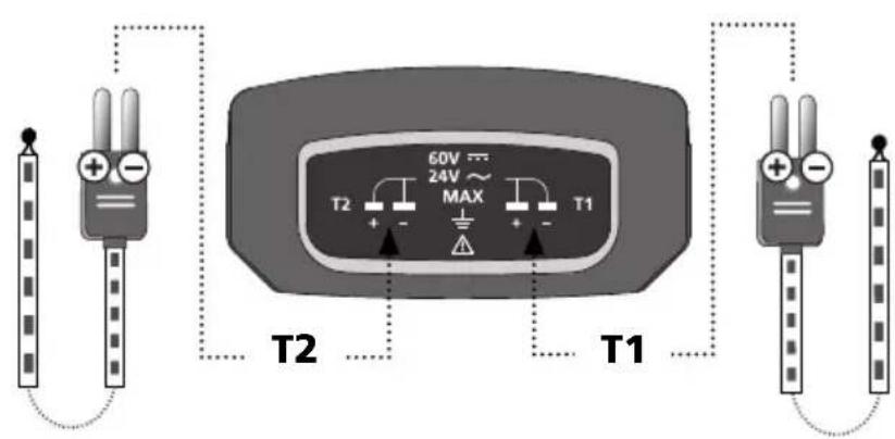
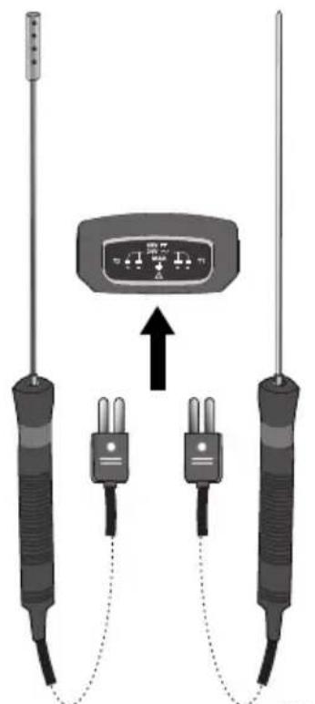
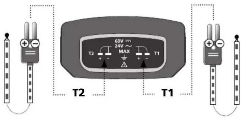
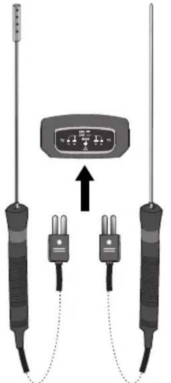
2 Connection of K-type thermocouples
text_image
60V 24V MAX T2 + - T1 T2 T1082.035.2082.035.1
text_image
Diagram showing two thermocouple sensors connected to a display with labeled ports and an upward arrow indicating connection.!
Pay attention to the polarity information on the thermocouple as well as on the device connection.
text_image
1 Laserliner® ThermoMaster 2 12 13 11 10 9 0.1°/T1* 8 °C MAX H0.8 - - 5 6 7 T1 T1-T2 T2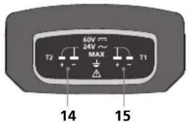
text_image
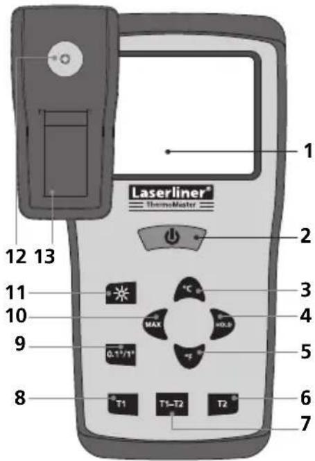
60V 24V~ MAX T2 + - T1 14 151 LC display, 3.5 segments, max. 1999
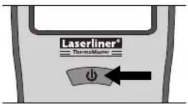
2 ON/OFF
3 Degrees Celsius
4 Hold current measured value
5 Degrees Fahrenheit
6 Temperature K-type input T2
7 Differential temperature K-type input T1-T2
8 Temperature K-type input T1
9 Measured value resolution
10 MAX value
11 Display illumination
12 1/4" tripod connection
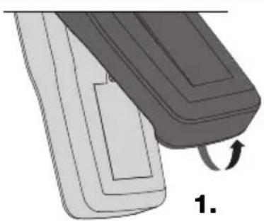
13 Battery compartment
14 K-type input T2
15 K-type input T1
text_image
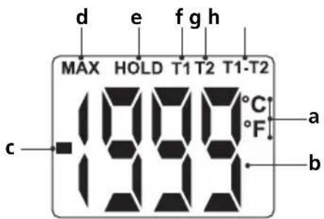
d e f g h MAX HOLD T1 T2 T1-T2 °C °F a b ca Units: Degrees Celsius/Fahrenheit
b Measured value
c Negative measured value
d MAX value
e Hold current measured value
f Temperature K-type input T1
g Temperature K-type input T2
h Differential temperature K-type input T1-T2
3 ON/OFF
text_image
Laserliner® Thermocenter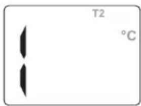
text_image
T2 °CThis display appears when no corresponding thermocouple is connected or the measuring range has been exceeded.
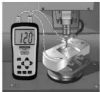
4 Temperature measurement (T1, T2, T1-T2)
The temperature T1 or T2 is measured and displayed by pressing button „T1“ or „T2“. A thermocouple (type K) must be plugged in at connection T1 or T2. The differential temperature can be determined by pressing button „T1-T2“ when thermocouples are plugged in at both connections.
natural_image
Laboratory setup with digital thermometer and mechanical components (no visible text or symbols)5 MAX-/HOLD function
The maximum temperature in an extended series of measurements is determined by pressing the „MAX” button. The HOLD function shows the last measurement or measured value in the display.
6 Measured value resolution (0.1 °C/1.0 °C)
This function changes the measurement resolution is changed between 0.1 °C and 1.0 °C. The resolution of 0.1 °C is particularly useful for measurements ≤100 °C where it is necessary to determine the temperature exactly. A resolution of 1.0 °C is recommended for measuring higher temperatures.

The device should be checked regularly to ensure it is functioning correctly. Calibration intervals of 1 year are recommended.
| Technical data Subject to technical alterations 03.11. | |
| Measuring range, measuring system -50 °C ... 1300 °C | |
| Accuracy, measuring system-50 °C ... 0 °C0 °C ... 1000 °C1000 °C ... 1300 °C | ±2 °C±(0.5 % of displayed value +1 °C)±(0.8 % of displayed value +1 °C) |
| Resolution 0.1 °C/1 °C selectable | |
| Unit of measurement °C/°F selectable | |
| Measuring range, thermocoupleThermoProbe KThermoSensor AirThermoSensor Tip | -50 °C ... 800 °C-50 °C ... 800 °C-50 °C ... 800 °C |
| Accuracy, thermocoupleThermoProbe KThermoSensor AirThermoSensor Tip | ±2.5 K (-50 °C ... 200 °C)±2.5 K (-50 °C ... 333 °C)0.75 % (333 °C ... 800 °C)±2.5 K (-50 °C ... 333 °C)±0.75 % (333 °C ... 1200 °C) |
| Sensor (EN 60584-2) Replaceable sensor, type K | |
| Display LC display, 3.5 segments, (max. 1999) | |
| Power supply 1x 9 V alkaline battery (NEDA 1604, IEC 6F22) | |
| Operating temperature 0 °C ... 50 °C | |
| Storage temperature | -20 °C ... 60 °C, 10 % ... 70 % rH (non-condensating) |
| Dimensions 162 mm x 76 mm x 38.5 mm | |
| Weight (without battery) 0.21 kg | |
EU directives and disposal
This device complies with all necessary standards for the free movement of goods within the EU.
This product is an electric device and must be collected separately for disposal according to the European
Directive on waste electrical and electronic equipment.
natural_image
Illustration of a mechanical component with a curved arrow indicating rotation (no text or symbols)
text_image
2. θ 3.
text_image
4. 96V1 x 9V Typ (NEDA 1604, IEC 6F22)
text_image
Diagram showing two thermocouple sensors connected to a digital display with labeled ports and an upward arrow indicating measurement or signal flow.!
natural_image
Industrial machine setup with digital display and mechanical components (no visible text or symbols)5 MAX-/HOLD-functie
natural_image
Illustration of a mechanical component with a curved arrow indicating rotation (no text or symbols)
text_image
2. θ 3.
text_image
4. 96V1 x 9V Typ (NEDA 1604, IEC 6F22)
text_image
Diagram showing two thermocouple sensors connected to a display with labeled ports and an upward arrow indicating connection.!
natural_image
Laboratory setup with a digital thermometer and mechanical equipment (no visible text or symbols)5 MAX-/HOLD-funktion
natural_image
Illustration of two mechanical components with a curved arrow indicating rotation (no text or symbols)
text_image
2. θ 3.
text_image
4. 96Vnatural_image
Diagram of two thermocouple sensors connected to a display unit with an upward arrow indicating connection (no text or symbols present)!
natural_image
Industrial machine setup with digital display and mechanical components (no visible text or symbols)5 Fonction MAX/HOLD
natural_image
Illustration of a mechanical component with a curved arrow indicating rotation (no text or symbols)
text_image
2. θ 3.
text_image
4. 96V1 x 9V Typ (NEDA 1604, IEC 6F22)
natural_image
Diagram of three identical thermometers connected in a circuit with an indicator box (no text or symbols present)!
natural_image
Laboratory setup with a digital thermometer and mechanical equipment (no visible text or symbols)5 Función „MAX“/“HOLD”
natural_image
Illustration of two mechanical components with a curved arrow indicating rotation (no text or symbols)
text_image
2. θ 3.
text_image
4. 96V1 x 9V Typ (NEDA 1604, IEC 6F22)
natural_image
Diagram of two thermocouple sensors connected to a display unit with an upward arrow indicating connection (no text or symbols present)!
natural_image
Industrial machine setup with digital display and mechanical components (no visible text or symbols)5 Funzione MAX/HOLD
natural_image
Illustration of a mechanical component with a curved arrow indicating rotation (no text or symbols)
text_image
2. θ 3.
text_image
4. 96V1 x 9V Typ (NEDA 1604, IEC 6F22)
natural_image
Diagram of two thermocouple sensors connected to a display panel with an upward arrow (no text or symbols present)!
natural_image
Industrial machine setup with digital display and mechanical components (no visible text or symbols)5 Funkcja MAX/HOLD
natural_image
Illustration of two mechanical components with a curved arrow indicating rotation (no text or symbols)
text_image
2. θ 3.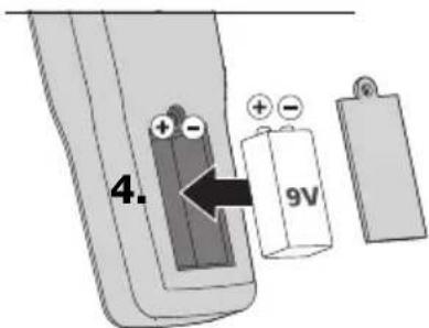
text_image
4. 9V1 x 9V Typ (NEDA 1604, IEC 6F22)
text_image
Diagram showing a sensor device connected to two identical thermometers with labeled ports and an upward arrow indicating signal flow.
text_image
d e f g h MAX HOLD T1 T2 T1-T2 °C °F a b c 888a Yksiköt:
Celsius/Fahrenheit
b Mittausarvo
natural_image
Industrial machine setup with digital display and mechanical components (no visible text or symbols)natural_image
Illustration of two mechanical components with a curved arrow indicating rotation (no text or symbols)
text_image
2. θ 3.
text_image
4. 96V1 x 9V Typ (NEDA 1604, IEC 6F22)
text_image
Diagram showing two thermocouple sensors connected to a digital display with labeled ports and an upward arrow indicating measurement or signal flow.!
natural_image
Industrial machine setup with digital display and mechanical components (no visible text or symbols)5 Função MAX/HOLD
natural_image
Illustration of a mechanical component with a curved arrow indicating rotation (no text or symbols)
text_image
2. θ 3.
text_image
4. 96V1 x 9V Typ (NEDA 1604, IEC 6F22)
natural_image
Diagram of two identical thermometers connected via wires to a display unit (no text or symbols visible)natural_image
Industrial machine setup with digital display and mechanical components (no visible text or symbols)5 MAX-/HOLD-funktion
natural_image
Illustration of a mechanical component with a curved arrow indicating rotation (no text or symbols)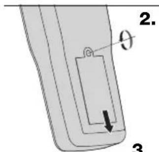
text_image
2. θ 3.3.

text_image
4. 96V1 x 9V Typ (NEDA 1604, IEC 6F22)
natural_image
Diagram of two thermocouple sensors connected to a display unit with an upward arrow indicating connection (no text or symbols present)
text_image
1 Laserliner® ThermoMaster 2 12 13 11 10 9 0.1"/T1" MAX °C H0.8 - - - 5 6 7 8 T1 T1-T2 T2
text_image
60V 24V~ MAX T2 + - T1 14 1515 K-type inngang T1

text_image
d e f g h MAX HOLD T1 T2 T1-T2 °C °F a b c 1000a Enheter: Grader Celsius/Fahrenheit
b Måleverdi
c Negativ måleverdi
d Maks.-verdi
natural_image
Industrial machine setup with digital display and mechanical components (no visible text or symbols)natural_image
Illustration of two mechanical components with a curved arrow indicating rotation (no text or symbols)
text_image
2. θ 3.
text_image
4. 96V1 x 9V Typ (NEDA 1604, IEC 6F22)
text_image
Diagram showing two thermocouple sensors connected to a digital display with labeled ports and an upward arrow indicating measurement or signal flow.!
natural_image
Industrial machine setup with digital display and mechanical components (no visible text or symbols)natural_image
Illustration of a mechanical component with a curved arrow indicating rotation (no text or symbols)
text_image
2. θ 3.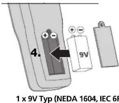
text_image
4. 9V 1 x 9V Typ (NEDA 1604, IEC 6F)natural_image
Diagram of three thermometers connected to a display unit with an upward arrow, no text or symbols present.!
text_image
d e f g h MAX HOLD T1 T2 T1-T2 °C °F a b c 888natural_image
Experimental setup with digital display and mechanical components (no visible text or symbols)natural_image
Illustration of two mechanical components with a curved arrow indicating rotation (no text or symbols)
text_image
2. θ 3.
text_image
4. 9V1 x 9V Typ (NEDA 1604, IEC 6F22)
natural_image
Diagram of two identical thermocouple sensors connected to a display unit with an upward arrow (no text or symbols present)!
natural_image
Industrial machine setup with digital display and mechanical components (no visible text or symbols)natural_image
Illustration of a mechanical component with a curved arrow indicating rotation (no text or symbols)
text_image
2. θ 3.3.

text_image
4. 96V1 x 9V Typ (NEDA 1604, IEC 6F22)
natural_image
Diagram of two test probes connected to a display unit with an upward arrow, no text or symbols present.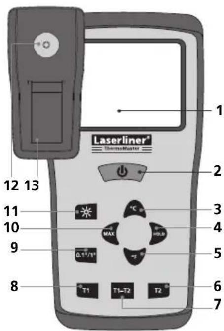
text_image
1 Laserliner® ThermoMaster 12 13 11 10 9 8 T1 T1-T2 T2 °C MAX H0.0 0.17/1° 5 6 7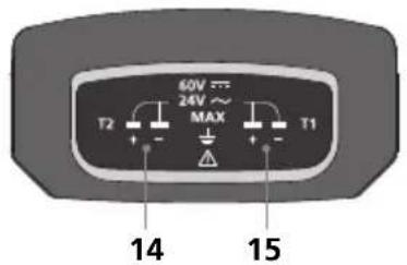
text_image
60V 24V~ MAX T2 + - T1 14 151 LC displej, 3 1/2 mist, max. 1999
2 ZAP/VYP
3 stupně Celsia
text_image
d e f g h MAX HOLD T1 T2 T1-T2 -999°C °F a bnatural_image
Industrial machine setup with digital display and mechanical components (no visible text or symbols)5 Funkce MAX/HOLD
natural_image
Illustration of a mechanical component with a curved arrow indicating rotation (no text or symbols)
text_image
2. θ 3.
text_image
4. 96V1 x 9V Typ (NEDA 1604, IEC 6F22)
natural_image
Diagram of two thermocouple sensors connected to a display unit with an upward arrow indicating connection (no text or symbols present)!
natural_image
Laboratory setup with a digital thermometer and mechanical equipment (no visible text or symbols)natural_image
Illustration of a mechanical component with a curved arrow indicating rotation (no text or symbols)
text_image
2. θ 3.
text_image
4. 96V1 x 9V Typ (NEDA 1604, IEC 6F22)
text_image
Diagram showing two thermocouple sensors connected to a digital display with labeled ports and an upward arrow indicating signal flow.!
natural_image
Industrial machine setup with digital display and mechanical components (no visible text or symbols)5 MAX/HOLD funkcija
natural_image
Illustration of a mechanical component with a curved arrow indicating rotation (no text or symbols)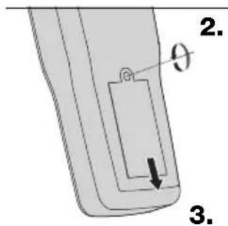
text_image
2. θ 3.
text_image
4. 96V1 x 9V Typ (NEDA 1604, IEC 6F22)
natural_image
Diagram of two thermocouple sensors connected to a display unit with an upward arrow indicating connection (no text or symbols present)!
text_image
d e f g h MAX HOLD T1 T2 T1-T2 °C °F a b c 888natural_image
Industrial machine setup with digital display and mechanical components (no visible text or symbols)5 Funkcija MAX / HOLD
natural_image
Illustration of a mechanical component with a curved arrow indicating rotation (no text or symbols)
text_image
2. θ 3.
text_image
4. 96V1 x 9V Typ (NEDA 1604, IEC 6F22)
natural_image
Diagram of two identical thermometers connected via wires to a display unit (no text or symbols visible)!
text_image
d e f g h MAX HOLD T1 T2 T1-T2 °C °F a b c 888a Unități:
Grade Celsius/Fahrenheit
b Valoare măsurată
natural_image
Industrial machine setup with digital display and mechanical components (no visible text or symbols)5 Functia MAX-/HOLD
natural_image
Illustration of a mechanical component with a curved arrow indicating rotation (no text or symbols)
text_image
2. θ 3.
text_image
4. 96V1 x 9V Typ (NEDA 1604, IEC 6F22)
2Извод на К-тип термоелементите
text_image
60V 24V MAX T2 T1 T2 T1082.035.2082.035.
natural_image
Diagram of two identical thermocouple sensors connected to a display unit with an upward arrow (no text or symbols present)!
text_image
d e f g h MAX HOLD T1 T2 T1-T2 °C °F a b c 888а Единици: градуси Целзий/Фаренхайт
b Измерена стойност
natural_image
Industrial machine setup with digital display and mechanical components (no visible text or symbols)5 MAX-/HOLD-функция
natural_image
Illustration of a mechanical component with a curved arrow indicating rotation (no text or symbols)
text_image
2. θ 3.
text_image
4. 9V1 x 9V Typ (NEDA 1604, IEC 6F22)
text_image
Diagram showing two temperature sensors connected to a display with labeled terminals and an upward arrow indicating direction.!
text_image
d e fgh MAX HOLD T1 T2 T1-T2 °C °F a b cnatural_image
Industrial machine setup with digital display and mechanical components (no visible text or symbols)natural_image
Illustration of a lathe machine tool operating on a CNC milling machine, with a digital temperature display showing 120°C (no text or symbols on the machine itself)SERVICE

Umarex GmbH & Co KG
- Laserliner -