ThermoMaster Plus Set - Thermometer Laserliner - Free user manual and instructions
Find the device manual for free ThermoMaster Plus Set Laserliner in PDF.

| Product type | Digital thermometer |
| Brand | Laserliner |
| Model | ThermoMaster Plus Set |
| Dimensions (W x H x D) | 75 x 167 x 35 mm |
| Weight (incl. batteries) | 216 g |
| Power supply | 4 batteries LR03 (AAA) 1.5 V |
| Measurement units | °C, K |
| Measuring range (type K) | -150 °C to 1370 °C |
| Measuring range (type J) | -150 °C to 1200 °C |
| Measuring range (type T) | -150 °C to 400 °C |
| Measuring range (type E) | -150 °C to 900 °C |
| Accuracy (from -100 °C to 1370 °C) | ± (0.1 % of measured value + 1 °C) |
| Accuracy (from -150 °C to -100 °C) | ± (0.2 % of measured value + 1 °C) |
| Resolution | 0.1 °C |
| Main functions | Temperature measurement, alarm, T2-T1 difference, Hold, Min/Max, average value, memory 10 locations, backlight, auto power off (20 min), digital connection |
| Compatible probe types | Thermocouple K, J, T, E |
| Wireless interface | Digital Connection (IEEE 802.15.4, Bluetooth LE ≥ 4.x) |
| Maintenance and cleaning | Clean with a slightly damp cloth; do not use solvents. Remove batteries for prolonged storage. |
| Safety | Use only within specifications; do not use in explosive environments or for medical diagnostics. Observe electromagnetic compatibility and RF instructions. |
| Repairability and spare parts | Calibration recommended once a year. Contact UMAREX-LASERLINER customer service for repairs. No spare parts listed. |
| Working conditions | 0 °C to 50 °C, max. humidity 80 % RH, max. altitude 2000 m |
| Storage conditions | -20 °C to 60 °C, max. humidity 80 % RH |
| Battery life | Approximately 100 hours |
| General information | User manual available in multiple languages. Compliant with WEEE directive. Visit laserliner.com for updates. |
Frequently Asked Questions - ThermoMaster Plus Set Laserliner
User questions about ThermoMaster Plus Set Laserliner
0 question about this device. Answer the ones you know or ask your own.
Ask a new question about this device
Download the instructions for your Thermometer in PDF format for free! Find your manual ThermoMaster Plus Set - Laserliner and take your electronic device back in hand. On this page are published all the documents necessary for the use of your device. ThermoMaster Plus Set by Laserliner.
USER MANUAL ThermoMaster Plus Set Laserliner
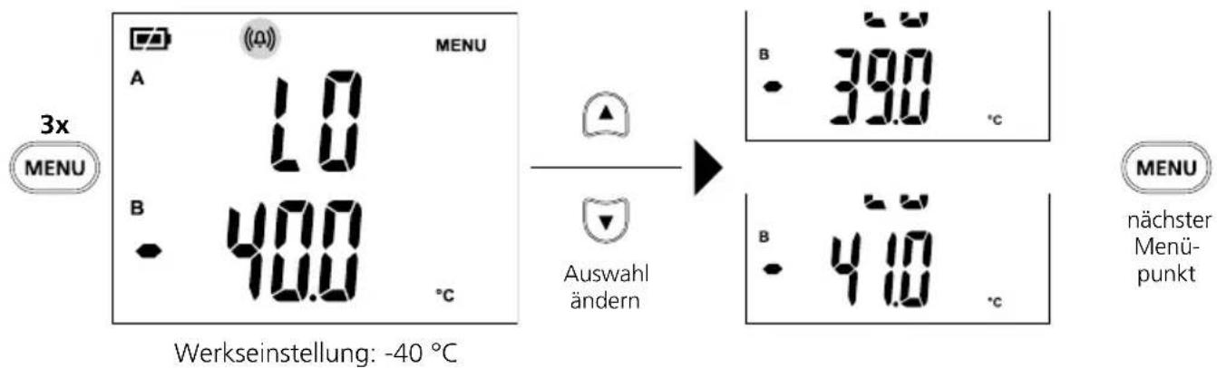
10 Tempersuralarm LO
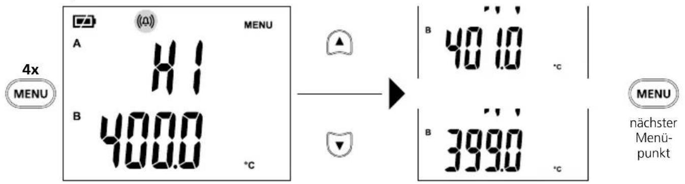
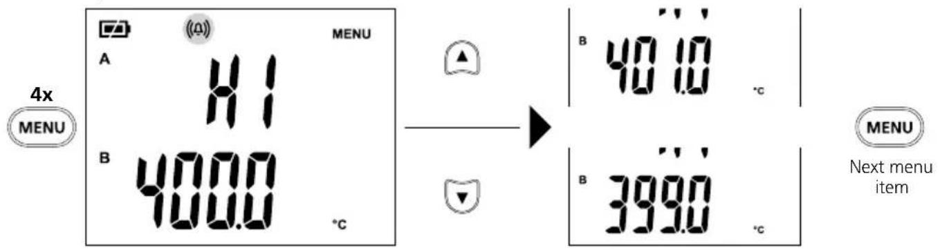
11 Tempersaturalarm HI
Werkseinstellung: 400^
Download on the App Store

GET IT ON Google Play
Completely read through the operating instructions, the „Warranty and Additional Information" booklet as well as the latest information under the internet link at the end of these instructions. Follow the instructions they contain. This document must be kept in a safe place and passed on together with the device.
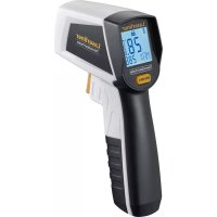
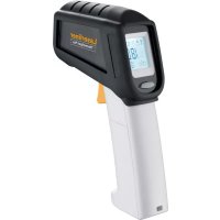
Function / Application
The digital thermometer is used to measure temperature and temperature differences with the aid of exchangeable type K/J/T/E thermocouples/sensors. The digital thermometer is predominantly used for temperature measurement in laboratories and in industrial applications. With the aid of the MAX function it is possible to determine limit temperature infringements in extended series of measurements.
General safety instructions
- The device must only be used in accordance with its intended purpose and within the scope of the specifications.
- Not suitable for potentially explosive areas or medical diagnoses.
- The measuring tools and accessories are not toys. Keep out of reach of children.
- Modifications or changes to the device are not permitted, this will otherwise invalidate the approval and safety specifications.
- Do not expose the device to mechanical stress, extreme temperatures, moisture or significant vibration.
- Do not power the thermocouple (K-type) with an external voltage.
- The device must no longer be used if one or more of its functions fail or the battery charge is weak.
- Please ensure compliance with the safety regulations set out by local and national authorities with regard to the correct and proper use of the device.
Safety instructions
Dealing with electromagnetic radiation
- The measuring device complies with electromagnetic compatibility regulations and limits in accordance with the EMC Directive 2014/30/EU which is covered by the Radio Equipment Directive 2014/53/EU.
- Local operating restrictions – for example, in hospitals, aircraft, petrol stations or in the vicinity of people with pacemakers – may apply. Electronic devices can potentially cause hazards or interference or be subject to hazards or interference.
- The measuring accuracy may be affected when working close to high voltages or high electromagnetic alternating fields.
Safety instructions
Dealing with RF radiation
- The measuring device is equipped with a wireless interface.
- The measuring device complies with electromagnetic compatibility and wireless radiation regulations and limits in accordance with the RED 2014/53/EU.
- Umarex GmbH & Co. KG hereby declares that the ThermoMaster Plus radio-based system complies with the requirements and other stipulations of the European Radio Equipment Directive 2014/53/EU (RED). The EU Declaration of Conformity can be found in its entirety at the following address:
http://laserliner.com/info?an=AHQ
Symbols
Warning about hazardous electrical voltage: Unprotected live components inside the device housing are capable of posing a risk of electric shock.

Protection class II: The test device has reinforced or double insulation.

Earth potential

Danger area warning

Read operating instructions
General instructions
- If the thermometer is subject to large fluctuations in the ambient temperature, after the temperature has stabilised, wait 20 minutes before performing a measurement.
- Always ensure adequate thermal coupling at the measuring point in order to avoid measuring errors caused by temperature loss.
- Please note that all thermometers with a contact sensor influence the measurement and their thermal capacity can reduce the actual temperature. More thermal energy should therefore be applied to the thermocouple than it can dissipate.
- Four lines will appear in line A if no thermocouple is connected.
- Lo or Hi will be displayed if the measured temperature is outside the measuring range.
- Only use the correct type of thermocouple (type K, J, T or E) and make sure that the device is set to the corresponding type. The wrong type can cause significant measuring errors.
- In addition to being subject to ageing, a thermocouple is also greatly depending on the operating conditions and should therefore be checked regularly.
- High pressure or mechanical deformation can change the grid structure and therefore have an influence on the thermoelectric voltage output.
- The thermometer and thermocouples have different measuring ranges and accuracies and therefore need to be considered separately.
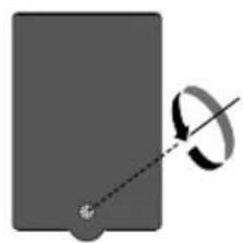
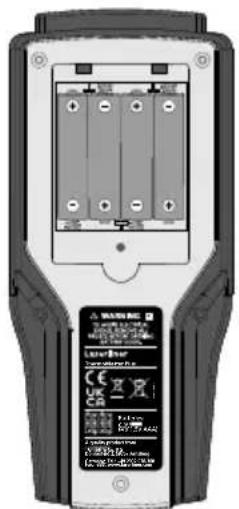
Inserting batteries
Open the battery compartment and insert batteries according to the symbols. Be sure to pay attention to polarity.
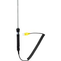
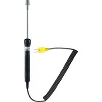
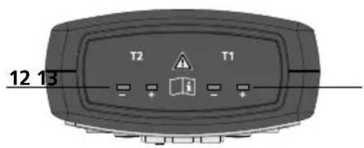
Connecting thermocouples
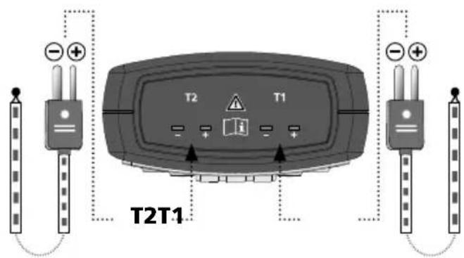
Pay attention to the polarity information on the thermocouple as well as on the device connection.
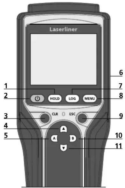
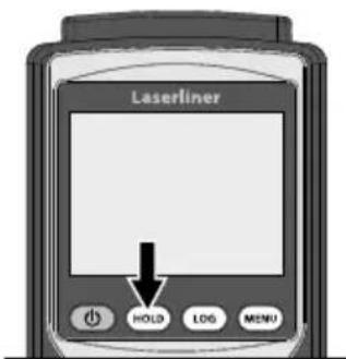
1 Hold current measured value
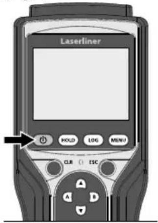
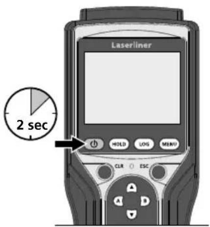
2 ON/OFF
3 Reset MAX/MIN/AVG;alarm OFF
4 Change menu selection
5 Show MAX/MIN/ AVG/T2-T1 for T1*
6 Battery compartment (rear)
7 Memory function
8 Settings menu
9 Exit menu / Switch off alarm
10 Show MAX / MIN / AVG / T1-T2 for T2*
11 Change menu selection
12 Input for thermocouple T2
13 Input for thermocouple T1
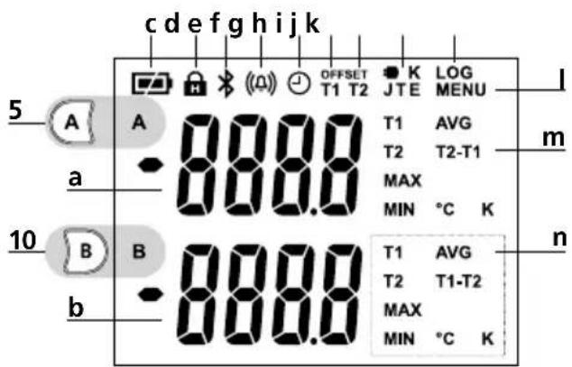
- Two connected thermocouples
** One connected thermocouple
a Measured value T1/ Measured valueT2**
b Measured value T2
c Battery charge
d HOLD function
e Digital Connection
f Alarm
g Auto power off
h Offset temperature T1
i Offset temperature T2
j Thermocouple type
k Memory
I Menu
m T2-T1: Value T2-T1
n T1:Thermocouple T1
T2:Thermocouple T2
MAX: MAX value
MIN: MAX value
AVG: Average value
T1-T2:Value T1-T2
^ C K: Units
ON OFF
4 HOLD function
The HOLD function shows the last measurement or measured value in the display.
Temperature measurement (T1, T2) With one thermocouple
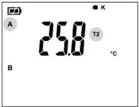
When measuring with one thermocouple, the measured value of the connected thermocouple T1 or T2 is shown in line A. The display shows whether T1 or T2 is connected.
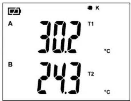
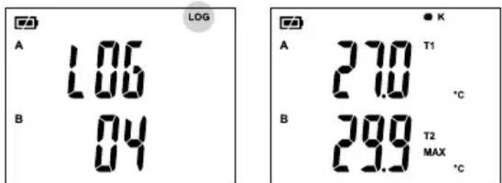
With two thermocouples
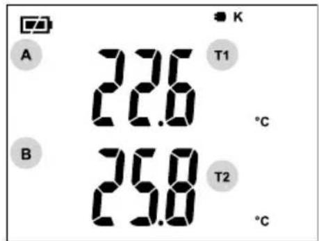
The measured value of thermocouple T1 is shown in line A and the measured value of thermocouple T2 in line B.
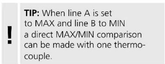
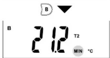
Show MAX / MIN / AVG / T2-T1
With one thermocouple
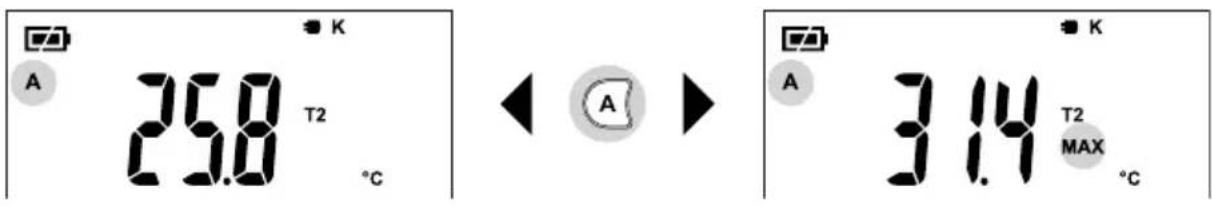
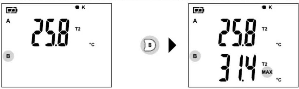
With two thermocouples (Example T1)

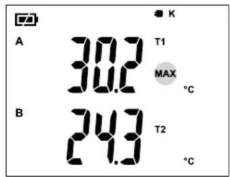

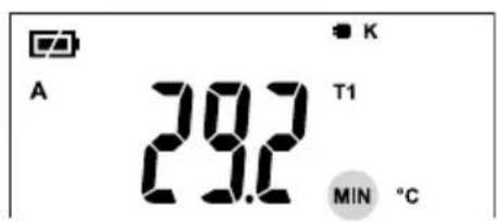

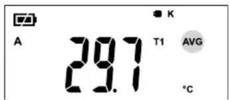
Press button A to show the MAX, MIN, AVG values of thermocouple T1 as well as the difference T2-T1.

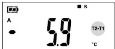
Press button B to show the MAX, MIN, AVG values of thermocouple T2 as well as the difference T1-T2.
7 Memory function / call up memory
The device has 10 storage locations.

The current measured value display is stored at the next free memory location by short-pressing the LOG button. An acoustic signals confirms successful storage.

The measured value memory is called up by long-pressing the LOG button. The measured value view and storage location are shown alternately.
Change storage location

The measured value memory is exited by short-pressing the ESC button.

Auto power off
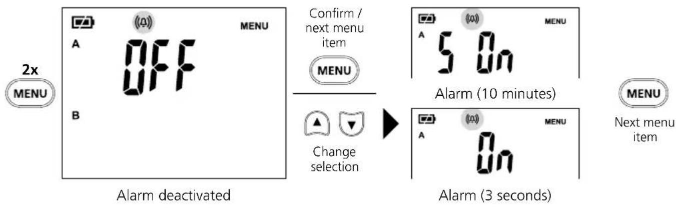
Temperature alarm
By activating the "Temperature alarm" function, deviations from the required temperature range are indicated by the (f) symbol on the display flashing and a two-stage (10 minutes / 3 seconds) acoustic signal. The temperature alarm can be cancelled by pressing the ESC button and is set to "OFF" in the menu.
You can set the temperature range, see section 10 „Temperature alarm LO" and section 11 „Temperature alarm HI".
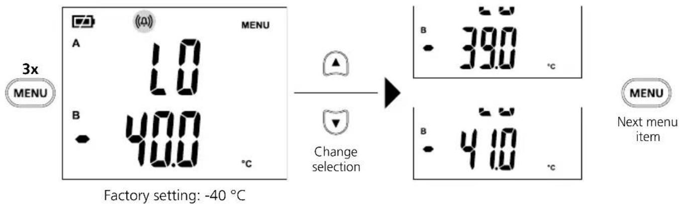
Temperature alarm LO
11
Temperature alarm HI
Factory setting: 400^
12
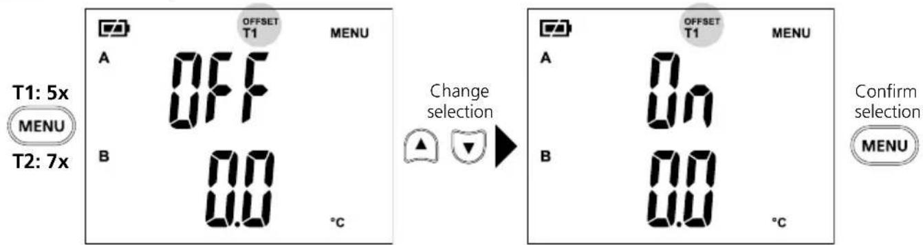
Offset temperature T1 / T2
Offset T1 activated Offset T1 deactivated
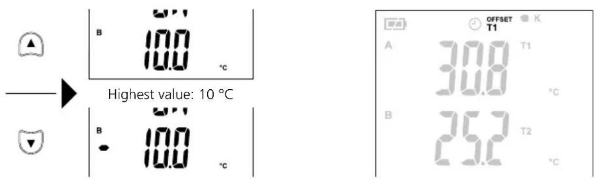
Lowest value: -10 °C
The display shows that an offset temperature is set.
13
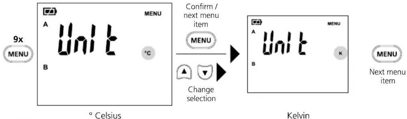
Setting unit of temperature
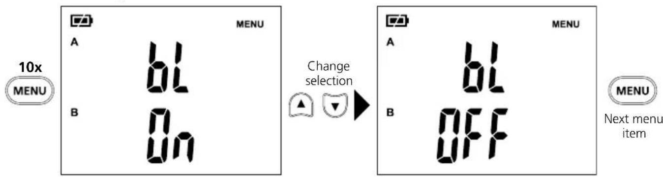
14 LCD backlight
15 Setting type of thermocouple
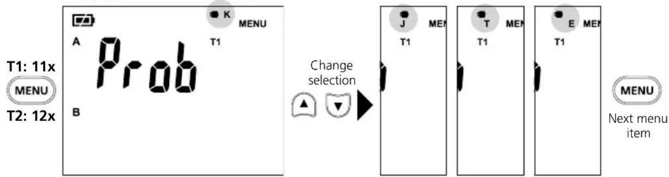
Type EType TType JType K
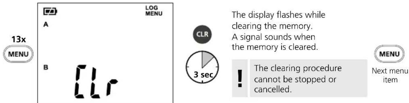
16 Clearing memory
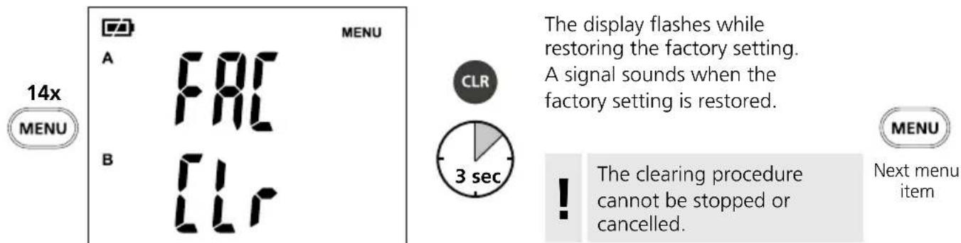
17 Restoring factory setting
18 Standard view
The display is reset to the standard view (view after switching on with thermocouple connected) by unplugging and reconnecting a thermocouple. The standard view can also be set by pressing the ESC button.
Data transfer
This device has digital connectivity which allows wireless data transfer to mobile devices such as smart phones or tablets with a wireless interface.
The system prerequisites for a digital connection are specified at http://laserliner.com/info?an=ble
This device can generate a wireless connection to devices which are compatible with the wireless standard IEEE 802.15.4. The wireless standard IEEE 802.15.4 is a transfer protocol for Wireless Personal Area Networks (WPAN). The range is set to a maximum distance of 10m from the terminal device and greatly depends on the ambient conditions such as the thickness and composition of walls, sources of interference as well as the transmit / receive properties of the terminal device.
Application (app)
An app is required to use the digital connection.
You can download the app from the corresponding stores for the specific type of terminal device:

Download on the App Store

GET IT ON Google Play

Make sure that the wireless interface of the mobile device is activated.
After starting the app and activating the digital connection, a connection can be set up between a mobile device and the measuring device.
If the app detects several active measuring devices, select the matching device.
This measuring device can be connected automatically the next time it is switched on.
Information on maintenance and care
Clean all components with a damp cloth and do not use cleaning agents, scouring agents and solvents. Remove the battery pack before storing for longer periods. Store the device in a clean and dry place. Do not touch the lens.
Calibration
The measuring device must be calibrated and tested on a regular basis to ensure it is accurate and working properly. We recommend carrying out calibration once a year. Contact your distributor or the UMAREX-LASERLINER service department.
| Technical Data Subject to technical changes without notice. 21W42 | |
| Measured variable Contact temperature | |
| Functions | Alarm, continuous measurement, difference, hold, MIN/MAX, Mean value |
| Contact temperature measuring range | Type K: -150°C ... 1370°C Type T: -150°C ... 400°C Type J: -150°C ... 1200°C Type E: -150°C ... 900°C |
| Contact temperature accuracy At ambient temperature 18°C ... 28°C: -150°C ... -100°C (±(0.2% of measured value + 1°C)) -100°C ... 1370°C (±(0,1% of measured value + 1°C)) | |
| Contact temperature resolution 0,1°C | |
| Thermocouple measuring range -60°C ... 300°C | |
| Interface Digital Connection | |
| Connections Thermocouple type K/J/T/E | |
| Unit of temperature °C (Celsius), K (Kelvin) | |
| Memory 10 storage locations | |
| Auto power off after 20 minutes | |
| Power supply 4 x 1.5V LR03 (AAA) | |
| Operating time approx. 100 hours | |
| Radio module operating data IEEE 802.15.4. LE ≥ 4.x (Digital Connection) interface; Frequency band: ISM band 2400-2483.5 MHz, 40 channels; Transmission power: max. 10 mW; Bandwidth: 2 MHz; Bit rate: 1 Mbit/s; Modulation: GFSK/FHSS | |
| Operating conditions | 0°C ... 50°C, max. humidity 80% rH, no condensation, max. working altitude 2000 m above sea level |
| Storage conditions | -20°C ... 60°C, max. humidity 80% rH, no condensation |
| Dimensions (W x H x D) | 75 x 167 x 35 mm |
| Weight | 216 g (incl. batteries) |
EU directives and disposal
This device complies with all necessary standards for the free movement of goods within the EU.
This product is an electric device and must be collected separately for disposal according to the European Directive on waste electrical and electronic equipment.
Further safety and supplementary notices at: http://laserliner.com/info?an=AHQ

!
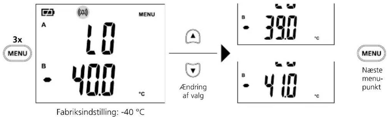
10 Tempersuralarm LO

11 Tempersuralarm HI
Fabriksindstilling: 400^
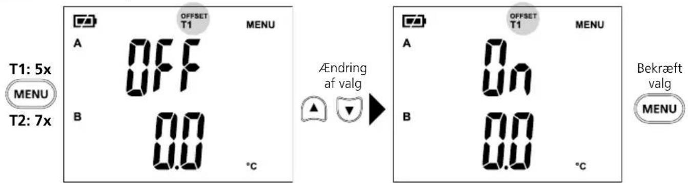
Offset-temperatur T1 / T2
Offset T1 aktiveretOffset T1 deaktiveret

Download on the App Store

GET IT ON Google Play


Download on the App Store

GET IT ON Google Play