GWS 18V10 Professional - Coffee grinder BOSCH - Free user manual and instructions
Find the device manual for free GWS 18V10 Professional BOSCH in PDF.
User questions about GWS 18V10 Professional BOSCH
0 question about this device. Answer the ones you know or ask your own.
Ask a new question about this device
Download the instructions for your Coffee grinder in PDF format for free! Find your manual GWS 18V10 Professional - BOSCH and take your electronic device back in hand. On this page are published all the documents necessary for the use of your device. GWS 18V10 Professional by BOSCH.
USER MANUAL GWS 18V10 Professional BOSCH
YkpaHcbka ..CtopiKa 265
Kaak. 8er 281
Romàna . Pagina 296
BbIrapckn .. CtpaHua 311
MaKeDoHcN.. CtpaHua 326
Srpski Strana 341
Slovenscina Stran 355
General Power Tool SafetyWarnings
WARNING
Read all safety warnings and all instructions. Failure to follow the warn
ings and instructions may result in electric shock, fire and/or serious injury.
Save all warnings and instructions for future reference.
The term "power tool" in the warnings refers to your mains-operated (corded) power tool or battery-operated (cordless) power tool.
Work area safety
- Keep work area clean and well lit. Cluttered or dark areas invite accidents.
Do not operate power tools in explosive atmospheres, such as in the presence of flammable liquids, gases or dust. Power tools create sparks which may ignite the dust or fumes. - Keep children and bystanders away while operating a power tool. Distractions can cause you to lose control.
Electrical safety
Power tool plugs must match the outlet. Never modify the plug in any way. Do not use any adapter plugs with earthed (grounded) power tools. Unmodified plugs and matching outlets will reduce risk of electric shock.
Avoid body contact with earthed or grounded surfaces, such as pipes, radiators, ranges and refrigerat
ors. There is an increased risk of electric shock if your body is earthed or grounded.
Do not expose power tools to rain or wet conditions. Water entering a power tool will increase the risk of electric shock.
Do not abuse the cord. Never use the cord for carrying, pulling or unplugging the power tool. Keep cord away from heat, oil, sharp edges or moving parts. Damaged or entangled cords increase the risk of electric shock.
When operating a power tool outdoors, use an extension cord suitable for outdoor use. Use of a cord suitable for outdoor use reduces the risk of electric shock..
If operating a power tool in a damp location is unavoidable, use a residual current device (RCD) protected supply. Use of an RCD reduces the risk of electric shock.
Personal safety
Stay alert, watch what you are doing and use common sense when operating a power tool. Do not use a power tool while you are tired or under the influence of drugs, alcohol or medication. A moment of inattention while operating power tools may result in serious personal injury.
Use personal protective equipment. Always wear eye protection. Protective equipment such as dust mask, non-skid safety shoes, hard hat, or hearing protection used for appropriate conditions will reduce personal injuries.
Prevent unintentional starting. Ensure the switch is in the off-position before connecting to power source and/or battery pack, picking up or carrying the tool. Carrying power tools with your finger on the switch or energising power tools that have the switch on invites accidents.
- Remove any adjusting key or wrench before turning the power tool on. A wrench or a key left attached to a rotating part of the power tool may result in personal injury.
Do not overreach. Keep proper footing and balance at all times. This enables better control of the power tool in unexpected situations.
Dress properly. Do not wear loose clothing or jewellery. Keep your hair, clothing and gloves away from moving parts. Loose clothes, jewellery or long hair can be caught in moving parts.
If devices are provided for the connection of dust extraction and collection facilities, ensure these are connected and properly used. Use of dust collection can reduce dust-related hazards.
Power tool use and care
Do not force the power tool. Use the correct power tool for your application. The correct power tool will do the job better and safer at the rate for which it was designed.
Do not use the power tool if the switch does not turn it on and off. Any power tool that cannot be controlled with the switch is dangerous and must be repaired.
- Disconnect the plug from the power source and/or the battery pack from the power tool before making any adjustments, changing accessories, or storing power tools. Such preventive safety measures reduce the risk of starting the power tool accidentally.
- Store idle power tools out of the reach of children and do not allow persons unfamiliar with the power tool or these instructions to operate the power tool. Power tools are dangerous in the hands of untrained users.
- Maintain power tools. Check for misalignment or binding of moving parts, breakage of parts and any other condition that may affect the power tool's operation. If damaged, have the power tool repaired before use. Many accidents are caused by poorly maintained power tools.
- Keep cutting tools sharp and clean. Properly maintained cutting tools with sharp cutting edges are less likely to bind and are easier to control.
Use the power tool, accessories and tool bits etc. in accordance with these instructions, taking into account the working conditions and the work to be performed. Use of the power tool for operations different from those intended could result in a hazardous situation.
Battery tool use and care
- Recharge only with the charger specified by the manufacturer. A charger that is suitable for one type of battery pack may create a risk of fire when used with another battery pack.
Use power tools only with specifically designated battery packs. Use of any other battery packs may create a risk of injury and fire.
When battery pack is not in use, keep it away from other metal objects, like paper clips, coins, keys, nails, screws or other small metal objects, that can make a connection from one terminal to another. Shorting the battery terminals together may cause burns or a fire.
Under abusive conditions, liquid may be ejected from the battery; avoid contact. If contact accidentally occurs, flush with water. If liquid contacts eyes, additionally seek medical help. Liquid ejected from the battery may cause irritation or burns.
Service
Have your power tool serviced by a qualified repair person using only identical replacement parts. This will ensure that the safety of the power tool is maintained.
Safety information for the angle grinder
SafetyWarnings common for Grinding, Sanding,Wire Brushing or Abrasive Cutting Off operations
This power tool is intended to function as a grinder, sander, wire brush or cut-off tool. Read all safety
22 | English
warnings, instructions, illustrations and specifications provided with this power tool. Failure to follow all instructions listed below may result in electric shock, fire and/or serious injury.
Operations such as polishing are not recommended to be performed with this power tool. Operations for which the power tool was not designed may create a hazard and cause personal injury.
Do not use accessories which are not specifically designed and recommended by the tool manufacturer. Just because the accessory can be attached to your power tool, it does not assure safe operation.
The rated speed of the accessory must be at least equal to the maximum speed marked on the power tool. Accessories running faster than their rated speed can break and fly apart.
The outside diameter and the thickness of your accessory must be within the capacity rating of your power tool. Incorrectly sized accessories cannot be adequately guarded or controlled.
- Threaded mounting of accessories must match the grinder spindle thread. For accessories mounted by flanges, the arbour hole of the accessory must fit the locating diameter of the flange. Accessories that do not match the mounting hardware of the power tool will run out of balance, vibrate excessively and may cause loss of control.
Do not use a damaged accessory. Before each use inspect the accessory such as abrasive wheels for chips and cracks, backing pad for cracks, tear or excess wear, wire brush for loose or cracked wires. If power tool or accessory is dropped, inspect for damage or install an undamaged accessory. After inspecting and installing an accessory, position yourself and bystanders away from the plane of the rotating accessory and run the power tool at maximum no load speed for one minute. Damaged accessories will normally break apart during this test time.
Wear personal protective equipment. Depending on application, use face shield, safety goggles or safety glasses. As appropriate, wear dust mask, hearing protectors, gloves and workshop apron capable of stopping small abrasive or workpiece fragments. The eye protection must be capable of stopping flying debris generated by various operations. The dust mask or respirator must be capable of filtrating particles generated by your operation. Prolonged exposure to high intensity noise may cause hearing loss.
- Keep bystanders a safe distance away from work area. Anyone entering the work area must wear personal protective equipment. Fragments of workpiece or of a broken accessory may fly away and cause injury beyond immediate area of operation.
Hold the power tool by insulated gripping surfaces only, when performing an operation where the cutting accessory may contact hidden wiring. Cutting accessory contacting a "live" wire may make exposed metal
parts of the power tool "live" and could give the operator an electric shock.
- Never lay the power tool down until the accessory has come to a complete stop. The spinning accessory may grab the surface and pull the power tool out of your control.
Do not run the power tool while carrying it at your side. Accidental contact with the spinning accessory could snag your clothing, pulling the accessory into your body.
Regularly clean the power tool's air vents. The motor's fan will draw the dust inside the housing and excessive accumulation of powdered metal may cause electrical hazards.
Do not operate the power tool near flammable materials. Sparks could ignite these materials.
Do not use accessories that require liquid coolants. Using water or other liquid coolants may result in electrocution or shock.
Kickback and RelatedWarnings
Kickback is a sudden reaction to a pinched or snagged rotating wheel, backing pad, brush or any other accessory. Pinching or snagging causes rapid stalling of the rotating accessory which in turn causes the uncontrolled power tool to be forced in the direction opposite of the accessory's rotation at the point of the binding.
For example, if an abrasive wheel is snagged or pinched by the workpiece, the edge of the wheel that is entering into the pinch point can dig into the surface of the material causing the wheel to climb out or kick out. The wheel may either jump toward or away from the operator, depending on direction of the wheel's movement at the point of pinching. Abrasive wheels may also break under these conditions.
Kickback is the result of power tool misuse and/or incorrect operating procedures or conditions and can be avoided by taking proper precautions as given below.
- Maintain a firm grip on the power tool and position your body and arm to allow you to resist kickback forces. Always use auxiliary handle, if provided, for maximum control over kickback or torque reaction during start-up. The operator can control torque reactions or kickback forces, if proper precautions are taken.
Never place your hand near the rotating accessory. Accessory may kickback over your hand.
Do not position your body in the area where power tool will move if kickback occurs. Kickback will propel the tool in direction opposite to the wheel's movement at the point of snagging.
Use special care when working corners, sharp edges etc. Avoid bouncing and snagging the accessory. Corners, sharp edges or bouncing have a tendency to snag the rotating accessory and cause loss of control or kickback.
Do not attach a saw chain woodcarving blade or toothed saw blade. Such blades create frequent kickback and loss of control.
SafetyWarnings specific for Grinding and Abrasive Cutting-Off operations
Use only wheel types that are recommended for your power tool and the specific guard designed for the selected wheel. Wheels for which the power tool was not designed cannot be adequately guarded and are unsafe.
The grinding surface of centre depressed wheels must be mounted below the plane of the guard lip. An improperly mounted wheel that projects through the plane of the guard lip cannot be adequately protected.
The guard must be securely attached to the power tool and positioned for maximum safety, so the least amount of wheel is exposed towards the operator. The guard helps to protect operator from broken wheel fragments, accidental contact with wheel and sparks that could ignite clothing.
Wheels must be used only for recommended applications. For example: do not grind with the side of cut-off wheel. Abrasive cut-off wheels are intended for peripheral grinding, side forces applied to these wheels may cause them to shatter.
Always use undamaged wheel flanges that are of correct size and shape for your selected wheel. Proper wheel flanges support the wheel thus reducing the possibility of wheel breakage. Flanges for cut-off wheels may be different from grinding wheel flanges.
Do not use worn down wheels from larger power tools. Wheel intended for larger power tool is not suitable for the higher speed of a smaller tool and may burst.
Additional SafetyWarnings specific for Abrasive Cutting Off operations
Do not "jam" the cut-off wheel or apply excessive pressure. Do not attempt to make an excessive depth of cut. Overstressing the wheel increases the loading and susceptibility to twisting or binding of the wheel in the cut and the possibility of kickback or wheel breakage.
Do not position your body in line with and behind the rotating wheel. When the wheel, at the point of operation, is moving away from your body, the possible kickback may propel the spinning wheel and the power tool directly at you.
When wheel is binding or when interrupting a cut for any reason, switch off the power tool and hold the power tool motionless until the wheel comes to a complete stop. Never attempt to remove the cut-off wheel from the cut while the wheel is in motion otherwise kickback may occur. Investigate and take corrective action to eliminate the cause of wheel binding.
Do not restart the cutting operation in the workpiece. Let the wheel reach full speed and carefully re-enter the cut. The wheel may bind, walk up or kickback if the power tool is restarted in the workpiece.
Support panels or any oversized workpiece to minimize the risk of wheel pinching and kickback. Large workpieces tend to sag under their own weight. Supports must be placed under the workpiece near the line of cut
and near the edge of the workpiece on both sides of the wheel.
Use extra caution when making a "pocket cut" into existing walls or other blind areas. The protruding wheel may cut gas or water pipes, electrical wiring or objects that can cause kickback.
SafetyWarnings specific for Sanding operations
Do not use excessively oversized sanding disc paper. Follow manufacturers recommendations, when selecting sanding paper. Larger sanding paper extending beyond the sanding pad presents a laceration hazard and may cause snagging, tearing of the disc, or kickback.
SafetyWarnings specific for Wire Brushing operations
Be aware that wire bristles are thrown by the brush even during ordinary operation. Do not overstress the wires by applying excessive load to the brush The wire bristles can easily penetrate light clothing and/or skin.
If the use of a guard is recommended for wire brushing, do not allow any interference of the wire wheel or brush with the guard. Wire wheel or brush may expand in diameter due to work load and centrifugal forces.
Additional Safety Information

Use suitable detectors to determine if there are hidden supply lines or contact the local utility company for assistance. Contact with electric cables can cause fire and electric shock. Damaging gas lines can lead to explosion. Breaking water pipes causes property damage.
Do not touch grinding and cutting discs until they have cooled down. The discs can become very hot while working.
Release the On/Off switch and set it to the Off position when the power supply is interrupted, e.g. when the battery pack is removed. This prevents uncontrolled restarting.
- Secure the workpiece. A workpiece clamped with clamping devices or in a vice is held more secure than by hand.
Do not open the battery. There is a risk of short-circuiting.

Protect the battery against heat, e.g. against continuous intense sunlight, fire, water, and moisture. There is a risk of explosion.
In case of damage and improper use of the battery, vapours may be emitted. Ensure the area is well-ventilated and seek medical attention should you experience any adverse effects. The vapours may irritate the respiratory system.
Use the battery only in conjunction with your Bosch product. This is the only way in which you can protect the battery against dangerous overload.
24 | English
The battery can be damaged by pointed objects such as nails or screwdrivers or by force applied externally. An internal short circuit may occur, causing the battery to burn, smoke, explode or overheat.
Caution! When using the power tool with Bluetooth a fault may occur in other devices and systems, aeroplanes and medical devices (e.g. pacemakers, hearing aids). Also, damage to people and animals in the immediate vicinity cannot be completely excluded. Do not use the power tool with Bluetooth in the vicinity of medical devices, petrol stations, chemical plants, areas with a potentially explosive atmosphere or in blasting areas. Do not use the power tool with Bluetooth* in aircraft. Avoid using the product near your body for extended periods.
The Bluetooth word mark and logos are registered trademarks owned by Bluetooth SIG, Inc. and any use of such marks by Robert Bosch Power Tools GmbH is under license.
Product Description and Specifications

Read all the safety and general instructions.
Failure to observe the safety and general instructions may result in electric shock, fire and/or serious injury.
Please observe the illustrations at the beginning of this operating manual.
Intended use
The power tool is intended for cutting, roughing and brushing metal and stone materials without the use of water.
A special protective guard for cutting must be used when cutting bonded abrasives.
Sufficient dust extraction must be provided when cutting stone.
With approved abrasive tools, the power tool can be used for sanding with sanding discs.
With the GCY 30-4 Bluetooth Low Energy Module that is fitted in the power tool, data and settings of the power tool can be transferred between the tool and a mobile device by means of Bluetooth wireless technology.
Product Features
The numbering of the product features refers to the diagram of the power tool on the graphics page.
(1) Unlocking lever for protective guard
(2) Direction of rotation arrow on housing
(3) Spindle lock button
(4) LED work light (GWS 18V-10 SC)
(5)User interface
(6) On/off switch
(7) Bluetooth module cover
(8) Battery
(9) Battery release button
(10) Auxiliary handle (insulated gripping surface)
(11) Protective guard for grinding
(12) Hub flange with O-ring
(13) Grinding disc
(14) Quick-clamping nut with bar
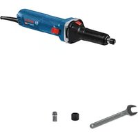
(15) Carbide grinding head
(16) Protective guard for cutting
(17) Cutting disc
(18) Handle (insulated gripping surface)
(19) Grinding spindle
(20) Hand guard
(21) Rubber sanding pad
(22) Abrasive disc
(23) Round nut
(24) Cup brush
(25) Diamond core cutter
(26) Button for charge indicator (GBA 18V...)
(27) Battery charge indicator (GBA 18V...) ^[9]
(28) Button for charge indicator (GBA 18V 6.3 Ah, ProCORE18V...)
(29) Battery charge indicator (GBA 18V 6.3 Ah, ProCORE18V...)
(30) Extraction guard for cutting with a cutting guide
(31) Diamond cutting disc
(32) Battery charge indicator (user interface)
(33) Speed preselection level indicator (user interface)
(34) Speed preselection button (user interface)
(35) Power tool status indicator (user interface)
(36) Overload protection indicator (user interface)
A) Accessories shown or described are not included with the product as standard. You can find the complete selection of accessories in our accessories range.
Technical Data
Angle grinder GWS 18V-10 C GWS 18V-10 C GWS 18V-10 C
| Article number | 3601 JG3 0.. 3601 JG3 2.. 3601 JG3 1.. |
| Rated voltage V= 18 18 18 | |
| Rated speed rpm 9000 9000 9000 |
English | 25
Angle grinder GWS 18V-10 C GWS 18V-10 C GWS 18V-10 C
| No-load speed rpm - - - | ||||
| Max. grinding disc diameter mm 100 115 125 | ||||
| Grinding spindle thread M 10 M 14 M 14 | ||||
| Max. thread length of grinding spindle mm 22 22 22 | ||||
| Kickback stop ● ● ● | ||||
| Restart protection ● ● ● | ||||
| Run-out brake ● ● ● | ||||
| Speed preselection - - - | ||||
| Weight according to EPTA Procedure 01:2014 | ||||
| - with additional low-vibration auxiliary handle | kg | \( {2.6}^{ \circ } - {2.8}^{ \circ } \) | \( {2.6}^{ \circ } - {2.8}^{ \circ } \) | \( {2.6}^{ \circ } - {2.8}^{ \circ } \) |
| - with standard auxiliary handle | kg | \( {2.4}^{ \circ } - {2.6}^{ \circ } \) | \( {2.4}^{ \circ } - {2.6}^{ \circ } \) | \( {2.4}^{ \circ } - {2.6}^{ \circ } \) |
| Permitted ambient temperature | ||||
| - during charging | °C | 0 to +45 | 0 to +45 | 0 to +45 |
| - during operation \( {}^{\mathrm{B})} \) and during storage | °C | -20 to +50 | -20 to +50 | -20 to +50 |
| Recommended batteries | GBA 18V... | GBA 18V... | GBA 18V... | |
| GBA 18V...W | GBA 18V...W | GBA 18V...W | ||
| ProCORE18V... | ProCORE18V... | ProCORE18V... | ||
| Recommended chargers | AL 18.. | AL 18.. | AL 18.. | |
| GAL 3680... | GAL 3680... | GAL 3680... | ||
| Recommended chargers for inductive batteries | GAL 18W... | GAL 18W... | GAL 18W... | |
| Data transmission | ||||
| \( {\text{Bluetooth}}^{a} \) | \( {\text{Bluetooth}}^{a}4.2 \)(Low Energy)\( ^c) \) | \( {\text{Bluetooth}}^{a}4.2 \)(Low Energy)\( ^c) \) | \( {\text{Bluetooth}}^{a}4.2 \)(Low Energy)\( ^c) \) | |
| Signal interval | s 888 | |||
| \( {\text{Max. signal range}}^{\mathrm{b})} \) | m 30 30 30 | |||
A)Depends on battery in use
B) Limited performance at temperatures < 0^
C) The mobile terminal devices must be compatible with Bluetooth® Low Energy devices (version 4.2) and support the Generic Access Profile (GAP).
D) The signal range may vary greatly depending on external conditions, including the receiving device used. The Bluetooth range may be significantly weaker inside closed rooms and through metallic barriers (e.g. walls, shelving units, cases, etc.).
| Angle grinder | GWS 18V-10SC | GWS 18V-10SC | GWS 18V-10SC | GWS 18V-10SC | |
| Article number | 3601 JG3 3.. | 3601 JG3 6.. | 3601 JG3 4.. | 3601 JG3 5.. | |
| Rated voltage | V= | 18 | 18 | 18 | 18 |
| Rated speed | rpm | 9000 | 9000 | 9000 | 7500 |
| No-load speed | rpm | 4500-9000 | 4500-9000 | 4000-7500 | |
| Max. grinding disc diameter | mm | 100 | 115 | 125 | 150 |
| Grinding spindle thread | M 10 | M 14 | M 14 | M 14 | |
| Max. thread length of grinding spindle | mm | 22 | 22 | 22 | 22 |
| Kickback stop | ● | ● | ● | ● | |
| Restart protection | ● | ● | ● | ● | |
| Run-out brake | ● | ● | ● | ● | |
| Speed preselection | ● | ● | ● | ● |
26 | English
| Angle grinder GWS 18V-10 | SC | GWS 18V-10 SC | GWS 18V-10 SC | GWS 18V-10 SC | |
| Weight according to EPTA Procedure 01:2014 | |||||
| - with additional low-vibration auxiliary handle | kg 2.6-2.8 | A) | 2.6-2.8A) | 2.6-2.8A) | 2.6-2.8A) |
| - with standard auxiliary handle kg 2.4-2.6 | A) | 2.4-2.6A) | 2.4-2.6A) | 2.5-2.7A) | |
| Permitted ambient temperature | |||||
| - during charging °C 0 to +45 0 to +45 0 to +45 0 to +45 | |||||
| - during operation B) and during storage °C -20 to +50 -20 to +50 -20 to +50 | |||||
| Recommended batteries GBA 18V... | GBA 18V... W ProCORE18V... | GBA 18V... W ProCORE18V... | GBA 18V... W ProCORE18V... | GBA 18V... W ProCORE18V... | |
| Recommended chargers AL 18.. | GAL 3680... | AL 18.. GAL 3680... | AL 18.. GAL 3680... | AL 18.. GAL 3680... | |
| Recommended chargers for inductive batteries | GAL 18W... | GAL 18W... GAL 18W... | GAL 18W... | GAL 18W... | |
| Data transmission | |||||
| Bluetooth* | Bluetooth*4.2 (Low Energy)C) | Bluetooth*4.2 (Low Energy)C) | Bluetooth*4.2 (Low Energy)C) | Bluetooth*4.2 (Low Energy)C) | |
| Signal interval s 88 8 8 | |||||
| Max. signal rangeD) | m 30 30 30 30 | ||||
A)Depends on battery in use
B) Limited performance at temperatures < 0^
C) The mobile terminal devices must be compatible with Bluetooth Low Energy devices (version 4.2) and support the Generic Access Profile (GAP).
D) The signal range may vary greatly depending on external conditions, including the receiving device used. The Bluetooth® range may be significantly weaker inside closed rooms and through metallic barriers (e.g. walls, shelving units, cases, etc.).
Noise/Vibration Information
| GWS 18V-10 C GWS 18V-10 C GWS 18V-10 C | ||||
| 3601 JG30.. 3601 JG32.. | 3601 JG31.. | |||
| Noise emission values determined according to EN 60745-2-3. | ||||
| Typically, the A-weighted noise level of the power tool is: | ||||
| Sound pressure level | dB(A) | 79 | 79 | 79 |
| Sound power level | dB(A) | 90 | 90 | 90 |
| Uncertainty K | dB | 3 | 3 | 3 |
| Wear hearing protection | ||||
| Total vibration values ah(triax vector sum) and uncertainty K determined according to EN 60745-2-3: | ||||
| Grinding surfaces (roughing): | ||||
| ah | m/s2 | 6.0 | 6.0 | 6.0 |
| K | m/s2 | 1.5 | 1.5 | 1.5 |
| Grinding with abrasive disc: | ||||
| ah | m/s2 | 3.5 | 3.5 | 3.5 |
| K | m/s2 | 1.5 | 1.5 | 1.5 |
English|27
| GWS 18V-10SC | GWS 18V-10SC | GWS 18V-10SC | GWS 18V-10SC | |
| 3601 JG3 3... 3 601 JG3 6.. 3 601 JG3 4.. 3 601 JG3 5.. | ||||
| Noise emission values determined according to EN 60745-2-3. | ||||
| Typically, the A-weighted noise level of the power tool is: | ||||
| Sound pressure level | dB(A) | 79 | 79 | 79 |
| Sound power level | dB(A) | 90 | 90 | 90 |
| Uncertainty K | dB | 3 | 3 | 3 |
| Wear hearing protection | ||||
| Total vibration values ah(triax vector sum) and uncertainty K determined according to EN 60745-2-3: | ||||
| Grinding surfaces (roughing): | ||||
| ah | m/s2 | 6.0 | 6.0 | 6.0 |
| K | m/s2 | 1.5 | 1.5 | 1.5 |
| Grinding with abrasive disc: | ||||
| ah | m/s2 | 3.5 | 3.5 | 3.5 |
| K | m/s2 | 1.5 | 1.5 | 1.5 |
The vibration level given in these instructions has been measured in accordance with a standardised measuring procedure and may be used to compare power tools. It can also be used for a preliminary estimation of exposure to vibration.
The stated vibration level applies to the main applications of the power tool. However, if the power tool is used for different applications, with different application tools or poorly maintained, the vibration level may differ. This can significantly increase the exposure to vibration over the total working period.
To estimate the exposure to vibration accurately, the times when the tool is switched off or when it is running but not actually being used should also be taken into account. This can significantly reduce the exposure to vibration over the total working period.
Implement additional safety measures to protect the operator from the effects of vibration, such as servicing the power tool and application tools, keeping the hands warm, and organising workflows correctly.
Fitting
Using the GCY 30-4 Bluetooth Low Energy Module
Note: The GCY 30-4 Bluetooth Low Energy Module is available as an accessory with GWS 18V-10 C power tools; it is included in the scope of delivery for GWS 18V-10 SC power tools.
Read the corresponding operating instructions for information about the GCY 30-4 Bluetooth' Low Energy Module.
Charging the Battery
Use only the chargers listed on the accessories page. Only these chargers are matched to the lithium-ion battery of your power tool.
Note: The battery is supplied partially charged. To ensure full battery capacity, fully charge the battery in the charger before using your power tool for the first time.
The lithium-ion battery can be charged at any time without reducing its service life. Interrupting the charging process does not damage the battery.
The lithium-ion battery is protected against deep discharge by the "Electronic Cell Protection (ECP)". When the battery is discharged, the power tool is switched off by means of a protective circuit: The application tool no longer rotates.
Do not continue to press the On/Off switch after the power tool has automatically switched off. The battery can be damaged.
Follow the instructions on correct disposal.
Removing the battery
The battery (8) is equipped with two locking levels to prevent the battery from falling out when pushing the battery release button (9) unintentionally. As long as the battery is inserted in the power tool, it is held in position by means of a spring.
28 | English
To remove the battery (8), press the release button (9) and pull the battery forward and out of the power tool. Do not use force to do this.
Battery charge indicator (battery model GBA 18V...) (see figure A)
The three green LEDs of the battery charge indicator (27) indicate the state of charge of the battery (8). For safety reasons, it is only possible to check the state of charge when the power tool is at a standstill.
Press the button (26) to display the state of charge. This is also possible when the battery (8) is removed.
LED Capacity
Continuous lighting 3 × green ≥ 2 / 3
Continuous lighting 2 × green ≥ 1 / 3
Continuous lighting 1 x green < 1/3
Flashing light 1 x green Reserve
If no LED lights up after pressing the button (26), then the battery is defective and must be replaced.
Note: The state of charge of the battery is also displayed on the user interface (5) (see "User interface (see figure D)", page 31).
Battery charge indicator (battery model GBA 18V 6.3 Ah, ProCORE18V...) (see figure B)
The five green LEDs of the battery charge indicator (29) indicate the state of charge of the battery. For safety reasons, it is only possible to check the state of charge when the power tool is at a standstill.
Press the button (28) to display the state of charge. This is also possible when the battery is removed.
LED Capacity
Continuous lighting 5 × green >80 - 100%
Continuous lighting 4 × green >60 - ≤ 80%
Continuous lighting 3 × green >40 - ≤ 60%
Continuous lighting 2 × green >20 - ≤ 40%
Continuous lighting 1 x green >0 - ≤ 20%
Flashing light 1 x green 0%
If no LED lights up after pressing the button (28), then the battery is defective and must be replaced.
Note: The state of charge of the battery is also displayed on the user interface (5) (see "User interface (see figure D)", page 31).
Fitting Protective Equipment
- Remove the battery from the power tool before carrying out work on the power tool (e.g. maintenance, changing tool, etc.). The battery should also be removed for transport and storage. There is risk of injury from unintentionally pressing the on/off switch.
Note: If the grinding disc breaks during operation or the holding fixtures on the protective guard/power tool become damaged, the power tool must be sent to the after-sales service immediately; see the "After-sales service and advice on using products" section for addresses.
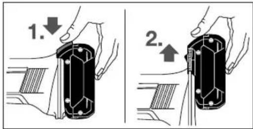
Protective guard for grinding

Place the protective guard (11) onto the holder on the power tool until the coding cams of the protective guard are aligned with the holder. When doing so, press and hold the unlocking lever (1).
Press the protective guard (11) onto the spindle collar until the shoulder of the protective guard is sitting on the flange of the power tool and rotate the protective guard until it audibly
clicks into place.
Adjust the position of the protective guard (11) to meet the requirements of the operation. To do this, push the unlocking lever (1) upward and rotate the protective guard (11) into the required position.
Always position the protective guard (11) such that all three red cam on the unlocking lever (1) engage in the corresponding openings on the protective guard (11).
Adjust the protective guard (11) such that sparking in the direction of the operator is prevented.
The protective guard (11) must only be adjustable while the unlocking lever (1) is actuated. Otherwise, the power tool must not be used any more under any circumstances and must be sent to the after-sales service.
Note: The coding camps on the protective guard (11) ensure that only a protective guard that is suitable for the power tool can be fitted.
Protective guard for cutting
Always use the protective guard for cutting (16) when cutting bonded abrasives.
Provide sufficient dust extraction when cutting stone.
The protective guard for cutting (16) is fitted in the same way as the protective guard for grinding (11).
Extraction guard for cutting with a guide block
The extraction guard for cutting with a guide block (30) is fitted in the same way as the protective guard for grinding (11).
Side handle
Do not operate your power tool without the side handle (10).
Screw the side handle (10) on the left or right of the machine head depending on how your are working.
Low-vibration auxiliary handle

The low-vibration auxiliary handle reduces vibration, enabling the tool to be used safely and more comfort
ably.
Do not make any alterations of any kind to the auxiliary handle.
Do not continue to use a damaged auxiliary handle.
Hand guard
Always fit the hand guard (20) when working with the rubber sanding pad (21) or with the cup brush/disc brush/flap disc.
Attach the hand guard (20) to the side handle (10).
Fitting the abrasive tools
- Remove the battery from the power tool before carrying out work on the power tool (e.g. maintenance, changing tool, etc.). The battery should also be removed for transport and storage. There is risk of injury from unintentionally pressing the on/off switch.
Do not touch grinding and cutting discs until they have cooled down. The discs can become very hot while working.
Clean the grinding spindle (19) and all the parts to be fitted. Lock the grinding spindle with the spindle lock button (3) before clamping and releasing the abrasive tools.
Do not press the spindle lock button while the grinding spindle is moving. The power tool may become damaged if you do this.
Grinding/Cutting Disc
Pay attention to the dimensions of the abrasive tools. The diameter of the hole must match that of the hub flange. Do not use an adapter or reducer.
When using diamond cutting discs, ensure that the arrow indicating the direction of rotation on the diamond cutting disc matches the direction of rotation of the power tool (see the direction of rotation arrow on the machine head).
See the graphics page for fitting instructions.
Use the quick-clamping nut (14) to secure the grinding/cutting disc without the need for additional tools.
Only use the quick-clamping nut (14) for grinding/cutting discs up to a maximum diameter of 150mm .
The quick-clamping nut (14) may be used only for grinding or cutting discs.
Only use quick-clamping nuts (14) that are in good working order and not damaged.
- When screwing on, make sure that the printed side of the quick-clamping nut (14) is not facing the grinding disc.
Always secure a grinding/cutting disc using only the quick-clamping nut (14) supplied.
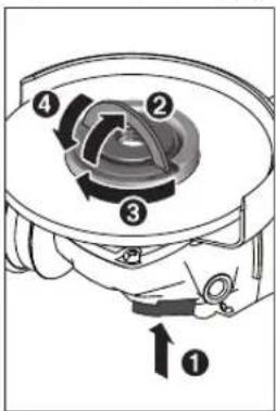
Press the spindle lock button (3) to lock the grinding spindle. To tighten the quick-clamping nut (14), fold up the bar and turn the quick-clamping nut firmly clockwise. Then fold down the bar to secure the quick-clamping nut. It is not sufficient to tighten the disc along the edge.
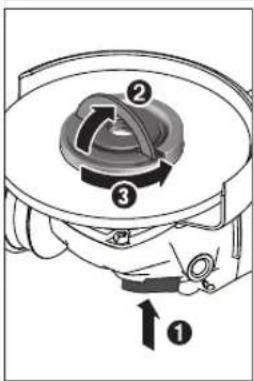
Quick-clamping nuts (14) that are properly secured and not damaged can be removed by hand. To do this, fold up the bar and turn the quick-clamping nut firmly anticlockwise. If the quick-clamping nut is stuck, do not attempt to loosen it with a tool - always use a two-pin spanner.
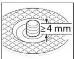
After fitting the hub flange and the grinding/cutting disc, the free thread length of the grinding spindle must be at least 4mm
Ensure that the abrasive tool is firmly seated, so that it does not twist away from
the spindle in the runout of the power tool.
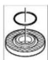
A plastic part (O-ring) is fitted around the center-ring collar in the hub flange (12). If the O-ring is missing or damaged, the hub flange (12) must be replaced before operation can resume.
After fitting the abrasive tool, check that the abrasive tool is fitted correctly and can turn freely before switching on the power tool. Make sure that the abrasive tool does not brush against the protective guard or other parts.
30 | English
Flap disc
Always fit the hand guard (20) when working with the flap disc.
Rubber Sanding Pad
Always fit the hand guard (20) when working with the rubber sanding pad (21).
See the graphics page for fitting instructions. Slide the rubber sanding pad (21) onto the grinding spindle (19).
Press the sanding sheet (22) firmly onto the underside of the rubber sanding pad (21).
Screw on the round nut (23) and tighten with a two-pin spanner.
Cup brush/disc brush
Always fit the hand guard (20) when working with the cup brush or disc brush.
See the graphics page for fitting instructions.
The cup brush/disc brush must be screwed onto the grinding spindle until it rests firmly against the grinding spindle flange at the end of the grinding spindle thread. Tighten the cup brush/disc brush with an open-ended spanner.
Carbide Grinding Head
A grinding head may be used only with a suitable protective guard.
Approved abrasive tools
You can use all the abrasive tools mentioned in these operating instructions.
The permissible speed [rpm] or the circumferential speed [m / s] of the abrasive tools used must at least match the values given in the table.
It is therefore important to observe the permissible rotational/circumferential speed on the label of the abrasive tool.
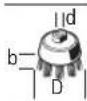
| max. [mm] [mm] | ||||
| D bd [rpm] [m/s] | ||||
| 100 | 7 | 16 | 9000 | 80 |
| 115 | 7 | 22.2 | 9000 | 80 |
| 125 | 7 | 22.2 | 9000 | 80 |
| 150 | 7 | 22.2 | 7500 | 80 |
| 100 | - | - | 9000 | 80 |
| 115 | - | - | 9000 | 80 |
| 125 | - | - | 9000 | 80 |
| 150 | - | - | 7500 | 80 |
7530M14900045
max.[mm][mm]
![BOSCH GWS 18V10 Professional - max.[mm][mm] - 1](/content/2026/04/601578/images/bed31ed45453112e0eca2c3e733e161bb3bcd2b6f5deb7620c79384ef1f1b783.jpg)
![BOSCH GWS 18V10 Professional - max.[mm][mm] - 2](/content/2026/04/601578/images/375f82b57807d191674175cd88f9ca2f4760f417375fa13287b869273a061a3b.jpg)
D bd [rpm] [m/s]
![BOSCH GWS 18V10 Professional - D bd [rpm] [m/s] - 1](/content/2026/04/601578/images/170c6b3ac8bd3dc8692623f1c42989694f0117d7d2a10ce142926f8c0aed32c5.jpg)
82-M14900080
Rotating the Machine Head (GWS 18V-10 C)
Remove the battery from the power tool before carrying out work on the power tool (e.g. maintenance, changing tool, etc.). The battery should also be removed for transport and storage. There is risk of injury from unintentionally pressing the on/off switch.
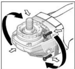
The machine head can be rotated in 90^ increments. In this way, the on/off switch can be brought into a more favourable handling position for particular applications, e.g. for left-handed tool users.
Completely unscrew the four screws. Rotate the ma
chine head carefully, without removing it from the housing, into the new position. Screw in and retighten the four screws.
Dust/Chip Extraction
Dust from materials such as lead-containing coatings, some wood types, minerals and metal can be harmful to one's health. Touching or breathing-in the dust can cause allergic reactions and/or lead to respiratory infections of the user or bystanders.
Certain dust, such as oak or beech dust, is considered carcinogenic, especially in connection with wood-treatment additives (chromate, wood preservative). Materials containing asbestos may only be worked by specialists.
-
Provide for good ventilation of the working place.
-
It is recommended to wear a P2 filter-class respirator.
Observe the relevant regulations in your country for the materials to be worked.
- Avoid dust accumulation at the workplace. Dust can easily ignite.
Operation
Start-up
Inserting the battery
Push the charged battery (8) into the base of the power tool from the front until the battery is securely locked.
Switching on/off
To start the power tool, push the on/off switch (6) forward.
To lock the on/off switch (6) in position, push the on/off switch (6) forward and down until it clicks into place.
To switch off the power tool, release the on/off switch (6); or, if the switch is locked, briefly push the on/off switch (6) backward and down and then release it.
Always check abrasive tools before using them. The abrasive tool must be fitted properly and be able to move freely. Carry out a test run for at least one minute with no load. Do not use abrasive tools that are damaged, run untrue or vibrate during use. Damaged abrasive tools can burst apart and cause injuries.
Kickback stop

If there is a sudden kickback in the power tool, e.g. jamming in a separating cut, the power supply to the motor will be interrupted electronically. The LED work light (4) then flashes white and the status indicator (35) flashes
red.
To restart the tool, set the on/off switch (6) to the off position and then switch the power tool on again.
Restart protection
The restart protection feature prevents the power tool from uncontrolled starting after the power supply to it has been interrupted.
When restart protection is activated, the status indicator (35) flashes red.
To restart the tool, set the on/off switch (6) to the off position and then switch the power tool on again.
Impact shutdown
The integrated impact shutdown switches the power tool off as soon as it hits the floor. The status indicator (35) then flashes red. To restart the tool, set the on/off switch (6) to the off position and then switch the power tool on again.
User interface (see figure D)
The user interface (5) is used to preselect the speed and to indicate the status of the power tool.
Speed Preselection (GWS 18V-10 SC)
You can use the button for speed preselection (34) to preselect the required speed, even during operation. The information in the table below describes the recommended values.
| Material Application Application tool Speed preselection level | GWS 18V-10 SC (100/115/125 mm) [rpm] | GWS 18V-10 SC (150 mm) [rpm] | ||
| Metal Brushing, removing rust | Cup brush 1 4500 4000 | |||
| Stainless steel | Grinding Fibre disc 2 6000 5500 | |||
| Metal Rough grinding Grinding disc 3 9000 7500 | ||||
| Metal Cutting Grinding disc 3 9000 7500 | ||||
| Stone Cutting Diamond cutting disc | and cutting guide (cutting stone is per-mitted only with a cutting guide) | 3 9000 7500 | ||
The values specified for speed levels are guide values.
The rated speed of the accessory must be at least equal to the maximum speed marked on the power
tool. Accessories running faster than their rated speed can break and fly apart.
Status indications
| Battery charge indicator (user interface) (32) | Meaning/cause Solution | |
| Green Battery charged - | ||
| Yellow | Battery almost empty | Replace or charge battery soon |
| Red | Battery empty | Replace or charge battery |
32 | English
Overload protection indicator (36)
Yellow Critical temperature has been reached (motor, electronics, battery)
Run the power tool at no load and allow it to cool down
Red Power tool is overheated and will switch off Leave the power tool to cool down
| Power tool status indicator (35) | Meaning/cause Solution | |
| Green Status OK - | ||
| Yellow Critical temperature has been reached or battery is almost empty | Run the power tool at no load and allow it to cool down, or replace or charge the battery soon | |
| Illuminated red Power tool is overheated or battery is empty Allow the power tool to cool down, or replace or charge the battery | ||
| Flashing red Kickback shutdown, restart protection or impact shutdown has been triggered | Turn the power tool off and on again | |
| Flashing blue Power tool is connected to a mobile device or settings are being transferred | - | |
Connectivity functions
In conjunction with the GCY 30-4 Bluetooth Low Energy Module, the following connectivity functions are available for the power tool:
- Registration and personalisation
- Status check, output of warning messages
- General information and settings
- Management
Read the corresponding operating instructions for information about the GCY 30-4 Bluetooth Low Energy Module.
Practical advice
- With the GCY 30-4 Bluetooth Low Energy Module, the power tool is equipped with a radio interface. Local operating restrictions, e.g. in aircraft or hospitals, must be observed.
Exercise caution when cutting slots in structural walls; see the "Information on structures" section. - Clamp the workpiece if it is not secure under its own weight.
Do not load the power tool so heavily that it comes to a stop.
If the power tool has been subjected to a heavy load, continue to run it at no-load for several minutes to cool down the accessory.
Do not use the power tool with a cut-off stand.
Do not touch grinding and cutting discs until they have cooled down. The discs can become very hot while working.
If the power tool becomes electrostatically charged, the built-in electronics will switch the power tool off. Press the on/off switch (6) again to restart the power tool.
Rough grinding
Never use cutting discs for rough grinding.
The best rough grinding results are achieved with a set angle of 30^ to 40^ . Move the power tool back and forth with moderate pressure. This will ensure that the workpiece does not become too hot or discolour and that grooves are not formed.
Flap disc
The flap disc (accessory) enables you to machine curved surfaces and profiles.
Flap discs have a considerably longer service life, lower noise levels and lower sanding temperatures than conventional grinding discs.
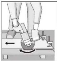
Cutting metal
Always use the protective guard for cutting (16) when cutting bonded abrasives.
When carrying out abrasive cutting, use a moderate feed that is suited to the material being machined. Do not exert pressure on the cutting disc and do not tilt or swing the power tool.
Do not attempt to reduce the speed of a cutting disc coming to a stop by applying pressure from the side.
The power tool must always work in an up-grinding motion. Otherwise there is a risk that it will be pushed uncontrolled out of the cut.
For best results when cutting profiles and rectangular tubing, start at the smallest cross section.
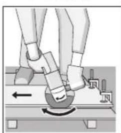
Cutting Stone (see figure)
C)
Provide sufficient dust extraction when cutting stone.
Wear a dust mask.
The power tool may be used only for dry cutting/grinding.
For best results when cutting stone, use a diamond cutting disc.
When using the extraction guard for cutting with a cutting guide (30), the vacuum cleaner must be approved for vacuuming stone dust. Suitable vacuum cleaners are available from Bosch.
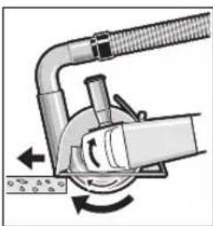
Switch on the power tool and position it with the front part of the cutting guide on the workpiece. Move the power tool with a moderate feed motion that is suited to the material being machined.
When cutting especially hard materials such as con
crete with a high pebble content, the diamond cutting disc can overheat and become damaged as a result. This is clearly indicated by circular sparking, rotating with the diamond cutting disc.
If this happens, stop cutting and allow the diamond cutting disc to cool down by running the power tool for a short time at maximum speed with no load.
If work is noticeably slower and with circular sparking, this indicates that the diamond cutting disc that has become dull. You can resharpen the disc by briefly cutting into abrasive material (e.g. lime-sand brick).
Information on structural design
Slots in load-bearing walls are subject to DIN 1053 part 1 or country-specific regulations. These regulations must be observed under all circumstances. Seek advice from the responsible structural engineer, architect or construction supervisor before starting work.
Recommendations for optimal handling of the battery
Protect the battery against moisture and water.
Only store the battery only within a temperature range of -20 to 50^ . Do not leave the battery in your car in the summer, for example.
Occasionally clean the ventilation slots on the battery using a soft brush that is clean and dry.
A significantly reduced operating time after charging indicates that the battery has deteriorated and must be replaced.
Follow the instructions on correct disposal.
Maintenance and Service
Maintenance and Cleaning
- Remove the battery from the power tool before carrying out work on the power tool (e.g. maintenance, changing tool, etc.). The battery should also be removed for transport and storage. There is risk of injury from unintentionally pressing the on/off switch.
To ensure safe and efficient operation, always keep the power tool and the ventilation slots clean.
Store and handle the accessories carefully.
After-sales service and advice on using products
Our after-sales service responds to your questions concerning maintenance and repair of your product as well as spare parts. You can find explosion drawings and information on spare parts at: www.bosch-pt.com
The Bosch product use advice team will be happy to help you with any questions about our products and their accessories.
In all correspondence and spare parts orders, please always include the 10-digit article number given on the nameplate of the product.
Great Britain
Robert Bosch Ltd. (B.S.C.)
P.O.Box 98
Broadwater Park
North Orbital Road
Denham Uxbridge
UB95HJ
At www.bosch-pt.co.uk you can order spare parts or arrange the collection of a product in need of servicing or repair.
Tel. Service: (0344) 7360109
E-Mail: boschservicecentre@bosch.com
Ireland
Origo Ltd.
Unit 23 Magna Drive
Magna Business Park
City West
Dublin 24
Tel. Service: (01) 4666700
Fax: (01) 4666888
Australia, New Zealand and Pacific Islands
Robert Bosch Australia Pty. Ltd.
Power Tools
Locked Bag 66
Clayton South VIC 3169
Customer Contact Center
Inside Australia:
Phone: (01300) 307044
Fax: (01300) 307045
Inside New Zealand:
Phone: (0800) 543353
Fax: (0800) 428570
Outside AU and NZ:
Phone: +61 395415555
www.bosch-pt.com.au
www.bosch-pt.co.nz
Republic of South Africa
Customer service
Hotline: (011) 6519600
Gauteng - BSC Service Centre
35 Roper Street, New Centre
Johannesburg
34 | Français
Tel.: (011) 4939375
Fax: (011) 4930126
E-Mail: bsctools@icon.co.za
KZN - BSC Service Centre
Unit E, Almar Centre
143 Crompton Street
Pinetown
Tel.: (031) 7012120
Fax: (031) 7012446
E-Mail: bsc.dur@za.bosch.com
Western Cape - BSC Service Centre
Democracy Way, Prosperity Park
Milnerton
Tel.: (021) 5512577
Fax: (021) 5513223
E-Mail: bsc@zsd.co.za
Bosch Headquarters
Midrand, Gauteng
Tel.: (011) 6519600
Fax: (011) 6519880
E-Mail: rbsa-hq.pts@za.bosch.com
Transport
The contained lithium-ion batteries are subject to the Dangerous Goods Legislation requirements. The batteries are suitable for road-transport by the user without further restrictions.
When shipping by third parties (e.g.: by air transport or forwarding agency), special requirements on packaging and labelling must be observed. For preparation of the item being shipped, consulting an expert for hazardous material is required.
Dispatch battery packs only when the housing is undamaged. Tape or mask off open contacts and pack up the battery in such a manner that it cannot move around in the packaging. Please also observe the possibility of more detailed national regulations.
Disposal

The machine, rechargeable batteries, accessories and packaging should be sorted for environmental-friendly recycling.
Do not dispose of power tools and batteries/ rechargeable batteries into household waste!
Only for EU countries:
According to the Directive 2012/19/EU, power tools that are no longer usable, and according to the Directive 2006/66/EC, defective or used battery packs/batteries, must be collected separately and disposed of in an environmentally correct manner.
Battery packs/batteries:
Li-ion:
Please observe the notes in the section on transport (see "Transport", page 34).
Français
Protection anti-redemarrage
Robert Bosch (France) S.A.S.
Montar as ferramentas delixar
Connectivity-functions
Satta in Bluetooth Low Energy Module GCY 30-4
Varvtalsforval (GWS 18V-10 SC)
Med knappen for varvtalsforval (34) kan du valja det varvral du behover, aven under drift. Uppgifterna i nedanstende tabell ar rekommenderade varden.
Bosch Service Center
Telegrafvej 3
2750 Ballerup
Danmark
Tel.: (08) 7501820 (inom Sverige)
Fax: (011) 187691
Transport
De litiumjonbatteri som ingar ar underkastade kraven for farligt gods. Anvandaren kan utan ytterligare forpliktelser transportera batterierna pa allman vag.
Overflatesliping (grovsliping):
| \( a_h \) | m/s² | 6,0 | 6,0 | 6,0 | 6,5 |
| K | m/s² | 1,5 | 1,5 | 1,5 | 1,5 |
| Sliping med slopeblad: | |||||
| \( a_h \) | m/s² | 3,5 | 3,5 | 3,5 | 3,0 |
| K | m/s² | 1,5 | 1,5 | 1,5 | 1,5 |
Vernedeksel for sliping

Legg vervedekselet (11) pa festet pa elektroverktoyet. Kodetappene pa vernedekselet skal stemme overens med festet. Mens du gjor dette,trykker du pa utøserspaken (1) og holder den innate. Trykk vervedekselet (11) pa spindelhalsen helt til kragen pa vervedekselet sitter pa flensen til elektroverktoyet, og drei vervedekselet til det hores at det festes.
Huomioi haviysohejeet.
Hoito ja huoIto
Huolto ja puhdistus
Avakpounkai oxetukc npoeiobonouoec
H avakoun eivai jia Eaovikn avtbpao n e evaaykwa n okaawma tou nepiotepoevou biokou, Tou diakou otnpienc, TNC BOUPOAC n kanoiou dAou eApntmuoc. To aykwaa n okaawda npokaletnv taxela akvntonoiou tou nepiotepoevou eApntmuoc, to onioe peTneipou unoxpevei to n eEvxoe neKtpko epyalevo kivntheta tN KATEUuvan AvtBeta ot npietpoof Tou eApntmuoc oTO onueio enuokhc.
Ia napabeiyia, eav evac blokoc aeivancy kwoei n okaawoei oe eva eneepya0evo koumni, n akn tou biakou nou eioepctai oto onueio aykwatoc mnpoe va buthetai otny eipaveia tou uikou, me anotelaeqa tnv avamdanon n to "klotanua" tou bilokou. O diokoc mnpoe va netaxte ietre npoc tn cepia tou xeiaptn h va anouakpuvtheta ano to xeiptn, avaloya me tvn kateuovan tnc kivnonc tou bilakou oto onueio aykwatoc. Ot bilokoc aeivanc mnpoe enlanc va onaoouv katno autec tic ouvthkec.
Havakpouan elvai to anotetaeqa tnc lavthetaaevnc xphong tou nkeptkoepyaleiou kai/n ADOc diaiaokaia xeiipapou n ouvthenkov kai mopoel va atoepuexhei, lajbaovvtac katalnA npolnntka petpa, onoc avapepovta napakatw.
Kpatate 0rahepa to nAektpko epyaaleo kai tonotheire to owa kaia to paxiovaacetouva unopeite vaavotaote oncduvapeic avakpouanc.
Xpnoooneite navtoT N npooetn Aa, eav unapxei, yiaeviato eeyxo tnc avakpuocn i TNC avidpaonc Tnc poinc kata tn diapkeia TNC ekivnonc. O xeiipntnc mnpel va eeyxie tnc avidpaoeic TNC poinc n Tc duvapeic avakpuocn, eav anfoov ta kataanla npolnnk aetpa.
Note mnu tonotheite to xepi oac kovta oTo nepoiotpeofoevo eapntma.To eapntma npopei va "kawtonoe" nawto xepiaoc.
Mny tonotheite to owa aac stny nepioxh, ony oonia tha petakvnei to naektpko epyaieio, oe nepittwn avakpouong. H avkapouna o whoaei to epyaleio otnv avrietn kateuuvan tnc kivngtou dlakou 0to aneio aykkwpatoc.
iDieteipnpooox,otavepyaceoeeywiec, KoPtepeacK.An.Anopeuyeteynv avanbnnonk Tnu eunokn Tou Eapntmuoc. Oy wvioc,oi Koptepec aknc n avanbnonexouv TnTn vaaykwovuTO nepiortpepoevoEApntma kai v npokaov anwlaia tou eEyyou avakpouan.
Mny tonotheiremu auaia npioiu, Aeniba EuoyAunikn oovotnt npiovOaJa. Teoiie Auec 6noupyov auxva avakpoun kai anxiae tou eEyxou.
PioeIbOnouoeic aopaaieic e6uk yuaepyaocc aeiaovn Kai kon
Xpnoonoei ovo tounc biokwv,oi onoiouviavtai yto nektpko epyaiao ca kal toeviko npopulaknpa, noiv elal oxediaevo ciaov enlemyevo biko. Oidikoi, yia touc onoiouc tonektpko epyaiao dev elal oxediaevo, dey mnpouva npotatcutouiv kavonoinkakel avapaaieic.
H emipaveta aeiaovanc wv kuptow biokw npenei va Bpioketai katw ano to enine do tou xieiaoc tou npopulaaktnpa. Evacakwc tonotheuvcicokoc, nou npoeexei and to enine do tou xieiaoc tou npopulaaktnpa dev npopei va npostateutel kavonoinikda.
O npopuakntpac npenei va eivai aopalaoc npoaaptnevoc oTo nAekptko epyaaleoi kai TOnoBetnpevoC yiaeyoi anopaia, etoi wte eva Elambdaoto tuiqa tou biokou va ektiotai npoc to pepoc Tou xeiipotn. O npopuakntpac oumbalai otnv npoataou xeiipotn ao onaoueva opaouata tou biokou, ano tuxaia enapf me tvov bioko kalouc npounpovva npokaleou avapaeEsigma poya.
Oi biokoi npenei va xponoionovtai mvo yia tic npoBlemevec epyaiec. Ia napadeyma: Mn aeivete me tny naeupa tou biokou konc. Oi biokoi konhnpoopiovra iyeippeiaekn kelavan, n eapapoyn naeupikovduvaewoeaweautouc Toudiokou mnpoei va npokaalei tn bpaon touc.
Xpnooe navto aoyec paVtzc biakw, oI onie exouv to owto meyockai oxnja yia tv eIeeyeo biokoc. Okaralnnce pAvtzec biakow unotnpoiouv tovi kai ouvenwc peiwovuyn Tnv mavnta 0paucn tou biakou. OpaVtzc yia touc
biakouc konhnc mnpel va elvat biapopetikc ano nC plavtcuov biakwV aeivanc.
Mnxpounoeire oapouoc biakouc ano eyautepa nektpka epyaleia.Evac diokoc nou npooipzetai yia eva eyautepo nektpko epyaieo dev elvai katalnoac yia tny unpntepn tauxtnta evoc mkpotepu epyaieoi kai nopoe va ondoe.
Piopo08eTc npoEiobonoiuec aoopaiaac i6ikayia epyaiec konic
Mny uJnlokapeTeTov bioko konnc nyn aokeite unepBoAiknieon. Mny enxieipnoete va kavetemu unepBoAkaBiaKaon. H unepBoAikn ieon oTo bioko auEavei To qopTIO kai Tny euaiaOia oe ouatpOph n Eunlokouoi bokoupeaa otNv toH kai Tduvatotnta avakpoan hbpauang tou biokou.
MnyeuypuqiTeTo owaacmuoTa hiaw anotov nepiopoepevo biok.OTAVO biaoc,OTOnnueioTNC epyaicac, kiveiral anopakpvouveoc ano to owaac,ma niavn avakpouon mnpel va kateuovieTov nepiopoepevo biokkai tonAektpko epyaaleio npoc topeocac.
Se nepiwn eun loknc tou biokou notav diakonei ma epyaia konc yia onoovbnote loyo, anevpyonoiote to naekpko epyaleio kai kpatnoTe to naekpko epyaleio akivno, mexvi va otapatnoei evteac o biokoc. Mny emxieipnote note va apaipaeote tv bioko konnc ano tv konl, otav o biokoc kveital, diaopopetka munpei va npokuay avakpuan. Epcuvntare kai abetae biopwtiká metpa yia va ealuyete nty atla tnc enlaohk tou biokou.
Mny enavekivoe T biadikia okeo ot eEepayoevo koupat. Apote to biokva ofoae otyn npn taxtnta kal eayete vava to biok npooektkae oovon. O biokoc mnpel va napouaidei emloan avamnoan avakpouan,otav ton Aektpiko epyaleio enavekivnei eo aoto eEepyaOevo koupati.
Σπριζετειαλακείη τη αυμεργεθη επεεργαζομενα κοματια, γιαναλαστοιοιθειοι κινδυονος εμλλοκής του διακουκανακρουσός. Ta μεγλα επεεργαζομενα κοματια τένουνν αναρουσίαουν καμη πος τα κατω λόγω του βάρους του. Πρεπειν τοῦθετούνται στηρίγματα κατω πότο επεεργαζομενον κοματια κοντά Πη γαρμηκόπες κανοντά Ακρητου επεεργαζομενου κοματιου κατό πός Πλευρές του διακου.
PpoexTe 1baitepa,otav kavete ma konn Oduaka) oe unapoxvtc toixouc n te tupae nepioxc. O biokoc nou pnoecximopei va koayei oawyve,napoxic aepiou ne vepoi,naekpiKaalwia anvtkiepeva,ta onoi mopoei va npokaaleoov avakpoun.
TpoeBOnouieic aaoaAeiac eibka yia epyaiec Tpiipatoc
Mn xnpaonoeite unepoLka peyalooye0c biokw yuaoxapou. Akoautheta tnc ouataoe c tou katakeuaat,otav emayetyuaoxapto.Eva
yea yuaoxapto npoeexei npao to biako
otnnc kivouvei va oxiotei kalnpoei na pokaloei
okawpa, axioo tou biakou avkpuon.
IpoeobonouoeaopaAeaac 6duka yuaepyaoiecpexpon oupuatobouptac
ExTe unOy nac, onl oUpMaTivec TpiXe cKivadaovrA ano T BoUptra akOn kai kata T diApkeia KavovnC letoupyiac. Mny nieZe tunePbOaKa Ta Oupuata, eapmuOZovrAC unepBoaIko FOPTIO nT BoUptra O1 oupuAtivec triXe mnpouv Eukola va bianepaoov Eaappa pouxa kalto depua.
Eav ouviatai npxhon evoc npopuakntpa yia n xpion oupatobouptac,6ev emtpeneta kajia napeunodion tou oupativou tpoxou nnc boptac ano tv npoquknpa. H diapetoc evoc oupativou tpoxou nboptac mopel va auEnbel an to poptlo epyadiac kal tic pvokvtec duvaeic.
PiopoeTeC unoeieic aoepaieac Opate npoataeutuk yuaia.

XpouoieKataaAneC oukeuec avxveuoc yia vaevtonoeTuxovn opatouc aywoouc tropofooiac nouboueute Tnv tomk etaipia npoxnc evpyiac. H enapn e naekpiouc aywoouc mnoepi va oynyoe ie npkayia kai naekponlaEla. H npoknan 2nmu c' evav aywyoqwaepiou (ykaio) mnpei va oynyoe ie ekpnE. To npunma evoc ubpaowna npokaale uikec 2nmuic.
Mny naoetouc biakouc aeiaovcn kai konic npotou va Kpuoouv. Oi biokoi kat Tnv cypaaia 6epaivovrata npap noA.
Aanaopaiaote tv diakontn ON/OFF kal theate tv onn Oean OFF,otav diakonei npopodooia peuataro,pi.x. Aoyw apaipeonc nnc mataipac. Etoeumodizeta n aveEeyktn enavekkivnoi tou.
Aopaiotoe neneepyaoevo koupat. Eva eneepyaoyeo koupatoukypatietai aopaleotepemuia diatae ng ouphiynncn pua neevnpa to xepiaoc.
Mny avoiyete nvy mnatapia. Ynapxekivouoc 3paayukkawatoc.

IpoataeTe Tnu mntapia ano unepBoLkEc 0epuokpaoiec, n. x. akoun kai ano ouvexnlaiknaktivoloia, qwiia, vepo ka uypaia. Ynpexi kivbuvoc ekpnnc.
Se nepiwnoan biaocn h/kai avtukavovikic xphong tnc matarapiac mnoepie va eEaouv avaouiaoeic ano tvmatarapia.Apnte va nei apekoc aepac kai eniokeptelre eva yiatpo av iaobavteire eoxlaoeic. OI avaouiaoeic mnpelva epebiouv ic avanveuotikc oouc.
Xpnooioe tnv mataipia mo o ouvdua o to npoiov Bosch. Movo etoi npootateu ta n mataipia ano ia eniklvuvn uneppoption.
16EeAynuKa
AnaoxnpaavtkeiEvaaocnX.kappiia n Kaouabidia ano exepukdoeknan buvannc mnopei va unootei nmuatapi. Mnpel va npoknol eva eowterko paayukkawmae anoteleaqa tny avapaleEn, Tnv eupvion karnvou, tny ekpnEn nTnv unepepavon nnc umatapiac.
Ppoox!KaraTnXpOonTou nEeKtpkuO epaAeiou Me Bluetooth"muopei va napouuaotei mia BAdn aAAWv oukeuwkai eykataotcwo,aeponawv kai atpukwovuekeuw (n.x. Bnpatobotnckapdaic, akouotka).Emionc devmuopei va anokleotei eveLwC ma znae avpwnockai zwa o aepoepenlavov.Mn xnpouonoieite to nEeKtpko epaAio 1e Bluetooth'kovtae iatpukecuovkeuec,otaohouc avepobiaapo, xnpukecykataotdaceic, emkvduve cyaekn npieoxc kai oe nepioxec avativewv. Mn xnpouonoieite to nEeKtpko epaAeo me Bluetooth"ce aeponlava.Anopoeyete Tn Aetoupyia via evapeyautepo xpovko biotma nolu kovta sto owpa ca.
To Aektu o nju Bluteoth onwc enionc ta Ekoovopma (ooyotuna) eiva kataxwpneva eunopka anura kal 1ioktnaia Tc Bluetooth SIG, Inc. Oonaihnote xan autw vw Aektuov anatw/ Ekoovopmuatw ano t Robert Bosch Power Tools GmbH npaypatonoitei aen oxtik adea xonnc.
Pepypapip npoiovtoc kaltoxoo

AiaBae 6aec Tc unoboeEic aopaaieic kai tOcbnyieC. H mtnpnn Tuv unoboeEow aoepalackavovobyivmopeiva npokaleoi nektponlaia, npkayia kai/ obaapouc,paupatouoc.
PiooEeTnapakaakw Tc Eikovec OTo mnpoov oepocTwv odnyuov Aetoupyiac.
Xpnooepwva eTov npooipopo
To nAektpko epyaaleo npooipietai yia konn, Eeovbipiaq kai Bouptaia maetaaikov kal netpvwv uikov xwioc tn xhon vepou.
TnV kon n e akamra paa aeavanc npenei va xnoonoinel evac idikocnpoaulkrtpac.
TnV konnt nptpwadv npene va povtioete yia pa enapk avappopnon oKovnc.
Me ta enipenoeva eapnataeiaiovnc unopei va xnpouonoinei to nekpkiopcyaaleio iaieanu yuaoxapto.
Ta deo eva kai o puiaicou tou nekpikou epyaleiou
unopovv vaetaepoov ae nepinwn xponc Bluetooth
Low Energy Module GCY 30-4 eaw tnac aupuatnc
Texyoloyiac Bluteoth melaue npktpoiou epyaleiou kaiac
kvntnc teakn oukeunc.
Anekoviciuova otoxieia
H anapiunan twv anteikoviciouevw otoxieiv avapepetai 0nty aeneiokovian tou nAektpikoEpyaaleiou ot aeia da ypaikow.
(1) MoXAc aTaaOpAiaIoc yia Tov npOuaKtIpa
(2) Béloç évδεiEnç φopac πeipotpocσo πeipβλμα
(3)Πλκτρο ακινητοποηστου ἀξονα
(4) Aùmè ἔργαδιας LED (GWS 18V-10 SC)
(5) △iaovbconxprn
(6)
(7) Káluμa tnc povδac Bluetooth
(8) Mnatapla
(9)TIAHKTPO aanaopaaIoc TNCμnataipacA
(10) PpOoBcTn λaBn (povwpevec enipapveic aλbnc)
(11)Προφιλακτίρας γαι λεῖανη
(12) Φλαντία unɔbɒxής με δακτύλιο στέγανονοηίης “O”
(13) i k e a
(14) PaEpaδi TauxuOooyEnc μe λaβn
(15)TnpoeiδncdiokocoknpoepaA
(16) PiofouλaKtIpaç yia konn
(17) l k c e a s^
(18) Xερολαβή (μονωμένες εἰπιφαένες λαβής)
(19) otov áEova λεiavon
(20) Piooataia xepotwA
(21) AaoiXevioC diokoc AieavonC
(22) o e i a v o n c^)
(23) Στρογυλύ παξμάδι
(24) Tnpooeiδης βούρτοα
(25) i t o k o p o v a^A)
(26) ΠΑΚΤΟ ΜΙΑ την εύδειξη Μις Κατάστοαπός φόρτιακ (GBA 18V...)
(27) EvseiKaataaonc fopntionc nataplac (GBA 18V...)
(28)Πλκτρο γιανην ενδεβεηπ καταστασης φόρτιασς (GBA 18V 6.3 Ah, ProCORE18V...)
(29) Evéién katàσaçn φòptionc μαntapiac (GBA 18V 6.3 Ah, ProCORE18V...)
(30) Ppoquakrtipac me avappoon yia tyn konn pe nla ohyannc
(31) (\Delta \mu \alpha \nu \tau \delta \delta \omega \kappa \kappa \kappa \kappa \kappa \kappa \kappa \kappa \kappa \kappa \kappa \kappa \kappa \kappa \kappa \kappa \kappa \kappa \kappa \kappa \kappa \kappa \kappa \kappa \kappa \kappa \kappa \kappa \kappa \kappa \kappa \kappa \kappa \kappa
(32) Evéiη κατασαπς φόρτιακ μηαταρλε (Διαύνδεοη χρήση)
(33) EvseIe npoβaθμiδac apiθμou σροφωv (Δiaovδeon xρηση)
(34) TAnKtpo npoemiloayic apiOou oTpoov (Auaovdeon xipn)
(35) Ev6eEgKataoTaOaCnAekTpiKou epyaaleiou (Aiaovv6eonxphotn)
(36) EvoeiEn npoostalac uneppoptwoonc (Aiaouvbeon xnoTn)
A) Eapnta nou anekovotn npepypovt aev neipexovta ont oavtap oukeuaia. Tov npkatao y eapntauov mopeite va tov pte iote npoypmae
TexvikaXapaktniptiKa
Atepeytooin npokpouo
H evawatouevn anevpyonoi npokpounc anepeyonoie to nkeptko epyaoleo, oiaic meto pia mwnxunoei oto danede. Tautoxpova n evbEn kataaoc (35) aavooohvekKiva. Ta nV enavaletoupia the tov diaokotn On/Off (6) onnv anepeyoonuev thon kai eeyponoiote to naktpko epyaelo ckvou.
Aiaovbveon xpoTn (BaeEikovaD)
H diaovbeon xphon (5) xpnaiueei yia nyn pnoenaioyn tou apiou tw oporow kaow kai yia nyn evdeien tnc katataang tou naektpikou epaaleiou.
Pioeuoytou apt0puo stpov (GWS 18V-10 SC)
Me to nAHTPO yia Tny npoemIoyn Tou apiOou Tuv otpoaw (34) mopeire va npocnIeTe ro anapaitno aipoiO otpoaw akoun kai kat dnapkeia tnc aeitoupyiac Ta oioxela oov nivaoka nou akolouei anoteoov mvo npoteivoeve c
Anevpyooinote kai evpyooinote eava to nkeptko epyaleo
mλe avaBoaβnVoua To nλekpio epyaieo elaw ouvdebepvo pe Tnv kivntn teAik oukeun netaqepovta puOlaic
Aetroupyie ouv6eouoTnTa
Se ouvouaouo me tvu Bluetooth Low Energy Module GCY 30-4 eivai diathetaueic oakouoe aetoupie c ouvbeoiotntac yia to nektpiko epyaelo:
-KataxwponkaiEeatojkuon
-ExyoKataoan, Ekoo nnuuatw npoeioolno
-Feviikc nAnpOopoplec kai puθμlaeic
-△axεipion
Tiaanpoopoplec oxetikae Tn Bluetooth Low Energy Module GCY 30-4 diaaote tic avtoioe oynie xepiaou.
YnobeiEic epyaiaic
To nAekpok oepyaleio e tonoetnnevblteoth Low Energy Module GCY 30-4 civa eonlaoevo e ma aopmuT npdaenapnc. O tonkoi nepiopoioi aeoupyiac, x. e aponlava h vovokoeia npenei va tnpouvtai.
PiooxN kata Tn xapaeyn eKoONv OE pepovtac toixouc, bene otnv evotnra Ynoedeieic yia tn statikn.
Σφιετοeneξεργαζόμενο κομμαι, εροσον δε σπηρίζεται σταθεράμε το δικό του βάρος.
Mn optovete npa nou to nektpko epyaieo, wote vaakvntonoeitr.
Meta ano meyaln katanovnan apnoTe ro nkeptpuo epyaieio akoum peipka lamva ouvexioeI n aeioupyia xwpiocpoptio, yia tny wuN tou eapntmuatoc.
Mnyxnpouponouocto nalektpkoepyaaleioe ouvduaouo euaiaaon konic.
Mny nuae touc biakouc leiavoq kal konic, npotou va kpuoouv. Oi biokoi kat Tnv epyaia oepaivovtai npap noA.
OTAV TO nAektpko epyaiao oopntoe nAektpootatka,TO evawpatuve noAektpovko ouanma anepeyonoie to nAektpko epyaiao. PAnote Tov biakotnOn/Off (6) EaV, va 0eae To nAektpko epyaiao EaV a eIoupyia.
三xovbipua
Mn xpnouonouoote note biokouc konic yia i a
Me yuvi kianc 30^ ec40 exe ta to Exovipua to kautepo anotelaqa epyaalac. Kivele to nkeptko epyaleo ue piaieon npa-6wOe. Eai to eneepya?oepo koumu t6 oepaivetao, 6v aala zei xpwa kai 66nmuoyovtaaukia.
AioKc IeiaovnCpepuHaapakua
Me tvd iako aeavonge ullapakia (eapthmuata) npopeire va eenepeyatoite enlanc kuptec emipaveic kai npopi. Oi biokoi aeavonge pfuallapakia exouv ma onauvikd uealutepn diapkeia zwn, mkpotepn staogun oopoukai xanotepn 0epuokpaoia leavang ano touv nuaevouc biakouc aeavong.
Konm μeταλοι
Kara tvn koni me depeva uukai eiaavnc Xpnaonoiite navtoe tov npouuakrtnpa yia koni (16).
Tc epyaie c konhc va epyaeote me petipnpoowon, npoapooevn oto eneepyazoevo uiko. Mny mieTe, nloeute nnu talaavwve te tv bioko konh. Mn opevape touc emiabuvovouc biokoc konh, meovtac touc naayic.
176 EAnnyuka
To nkeptko epyaaleo npenei va oynyeita navtote me avtiogtn kivnon. diaopoptika umpexi o kivouoc,va Eepuyie aeekayta an no tv konn.
KataTnV konnpoipkai
awanyov opoyoviknc
diatounc apxioe kautepa
otmukpotepn diatoum.
Konn netae (Bene eukova C)
Kata tyn konn oe neta povrtce yia pa enapki avapppon tnokovnc.
Φopáte μασκa npoσταiαc ano σκονη.
To nEeKtpko epyaleio entpenetra va xnpoumonounthetai mOvo yia epyaiec enpoc konic/Enpoc leiavanc.
Taslama makinesi GWS 18V-10 C GWS 18V-10 C GWS 18V-10 C
| Ağırkı EPTA-Procedure 01:2014 uyarıncı | ||||
| -Titresim emisi ek tutamaki kg 2,6-2,8 | A) | 2,6-2,8A) | 2,6-2,8A) | |
| - Standart ek tutamaki kg 2,4-2,6 | A) | 2,4-2,6A) | 2,4-2,6A) | |
| İzin verilen ortam sicutkıngı | ||||
| - Şarjda °C 0...+45 0...+45 0...+45 | ||||
| - İsletmede (B) sicutlklarda ve depolamada kılıtlı performans | °C-20...+50-20...+50-20...+50 | |||
| Tavsiye edilen aküler GBA 18V... | GBA 18V... | GBA 18V... | GBA 18V... | |
| GBA 18V... W | GBA 18V... W | GBA 18V... W | ||
| ProCORE18V... | ProCORE18V... | ProCORE18V... | ||
| Tavsiye edilen Şarj cihazlar AL 18.. | AL 18.. | AL 18.. | AL 18.. | |
| GAL 3680... | GAL 3680... | GAL 3680... | ||
| Endüktif aküler:içın tavsiye edilen Şarj cihazlar GAL 18W... GAL 18W... | ||||
| Veri aktarimi | ||||
| Bluetooth | Bluetooth 4.2(Low Energy)C) | Bluetooth 4.2(Low Energy)C) | Bluetooth 4.2(Low Energy)C) | |
| Sinyal mesafesi s 8 8 8 | ||||
| Maksimum sinyal erişim mesafesiD) | m | 30 | 30 | 30 |
| A) Kullanlan aküye baglidir | ||||
| B) <0°C sicutlklarda sinrlıperformans | ||||
| C) Mobil cihazlar Bluetooth -Low-Energy cihazlarina (Version 4.2) uyuml olmalı ve Generic Access Profile i (GAP) desteklemelidir. | ||||
| D) Erşim mesafesi kullanlan algilama cihazi da dahil olmak üzer diş kosullara güör onemli ölcüdedehyigkeit bilir. Kapali mekanlarda ve metal engeller olmasi durumunda (örnegin duvarlar, raflar, bavvullar vb.)Bluetooth® erişim mesafesi onemli ölcüde azalabilir. | ||||
| Taşa maki nesi | GWS 18V-10SC | GWS 18V-10SC | GWS 18V-10SC | GWS 18V-10SC |
| Ürün kodu | 3601 JG3 3.. | 3601 JG3 6.. | 3601 JG3 4.. | 3601 JG3 5.. |
| Anma gerilimi | V= | 18 | 18 | 18 |
| Devir sayisi | dak1 | 9000 | 9000 | 9000 |
| Boş+taki devir sayisi | dak1 | 4500-9000 | 4500-9000 | 4500-9000 |
| maks. taşa diski capi | mm | 100 | 115 | 125 |
| Taşa mili dişi | M 10 | M 14 | M 14 | |
| taşa milinin maksimum dişi kusim uzunluğu | mm | 22 | 22 | 22 |
| Geri tepme késmesi | ● | ● | ● | |
| Tekrar calisma emniyeti | ● | ● | ● | |
| Serbest)dönüş freni | ● | ● | ● | |
| Devir sayisi on seçimi | ● | ● | ● | |
| Ağırkı EPTA-Procedure 01:2014 uyarıncı | ||||
| -Titresim emici ek tutamaki | kg | 2,6-2,8A) | 2,6-2,8A) | 2,6-2,8A) |
| - Standart ek tutamaki | kg | 2,4-2,6A) | 2,4-2,6A) | 2,5-2,7A) |
| İzin verilen ortam sicutkıngı | ||||
| - Şarjda | °C | 0...+45 | 0...+45 | 0...+45 |
| - İsletmqde (B) sicutlklarda ve depolamada kılıtlıperformans | °C | -20...+50 | -20...+50 | -20...+50 |
| Tavsiye edilen aküler | GBA 18V... | GBA 18V... | GBA 18V... | |
| Taşlama makinesi GWS 18V-10 | GWS 18V-10 | GWS 18V-10 | |||
| SC | SC | SC | SC | ||
| GBA 18V... W | GBA 18V... W | GBA 18V... W | GBA 18V... W | ||
| ProCORE18V... | ProCORE18V... | ProCORE18V... | ProCORE18V... | ||
| Tavsiye edilen-SAŞar cihazları AL 18.. | AL 18.. | AL 18.. | AL 18.. | ||
| GAL 3680... | GAL 3680... | GAL 3680... | GAL 3680... | ||
| Endüktif aküler�能 tavsiye edilen-SAŞar cihazlari | GAL 18W... | GAL 18W... | GAL 18W... | ||
| Veri aktanimi | |||||
| Bluetooth* | Bluetooth*4.2(Low Energy)C | Bluetooth*4.2(Low Energy)C | Bluetooth*4.2(Low Energy)C | Bluetooth*4.2(Low Energy)C | |
| Sinyal mesafesi 8888 | |||||
| Maksimum sinyal erişim mesafesiD) | m 30 30 30 30 | ||||
Robert Bosch Sp. z o.o.
Bosch Service Center PT
KVapence 1621/16
692 01 Mikulov
Na www.bosch-pt.cz si si muzete objednat opravu Vaseho stroje nebo nahradni dily online.
TIN N nepHOJNUHOCbTexHNueCKOrO 6cbnyxHBaHH
PekomeHnyetcOuHCTnB HNCTpyMeHT OT nbIIN NOCNE KAKDOHCNOB3OBAHN.
Xpahenne
-Heo6xOIMO XpaHnB BCyXOMecTe
-HeoXOJMO XpaHnB BdAnOT NCTOCHNKOB NOBbIeH HbIX TEMepaTpy IN BO3JeCTBnCOnHeuHbIX Lyuei
- npn xpaHEnH Heo6xoHMo H36eRaTb pe3KOrO nepenada TemnepaTp
-xpaHHe 6e3 ynaKOBn He donyckaetc
- fnoopob6hble Tpe6oBAHHK yCIOBnAM XpaHEHnCMOTpHTe BTOCT 15150 (yCNOBne 1)
TpaHcnpTnpoBka
Kateropnueckn He donyckaetc naeHne HIO6bte mexaHneckne BO3dEcTBnHa ynaKOBy npn TpaHCnpTPOBKe
- npn pa3py3ke/nporpy3ke he donyckaeTcHcnoIb3oBaHne IIO6Oro Bna TeXHHK, pa60taUeH no npHHuNpy 3axmuaYNAKOBKN
- noDpO6HbIe Tpe6oBaHnK yCIOBnM TpaHcNOpTnPOBKn CMOTPHe BTOCT 15150 (yCIOBHe 5)
Yka3aHnnoTexHnke6e3oNaCHOCTN
06uhe yka3aHnno texnke 6e3onachoctn dnn 3neKtpoHHCTpymENTOB
A INPEyIPIE- XDEHNE
IpoHTTE BcE yKa3aHnH N HcTpyKuHnNo TexHnke 6e3oNaCHOCTN. Heco6nio
dHne yka3aHn HnctpyKu nnoTeXnKe 6eONacHOCTMOKe TcTb npuHHoN opaKeHHa 3JeKTPueCKHM TOKOM,POkapa N TaKeJIbIX TpaBM.
CoxpaHnTe 3THNCHtpKunuYka3aHaHnDn6yduo HcNoIb3OBAHn.
HcnoIb3oBaHHoe B HAcToaUx INHCTpyKUHX yKa3aHHX
HOHTME 3NEKTPOHCTPymENT paNpOcTpaHrETc HA 3NEK
TPOHCTPymENT C NITaHnEM OT cETN (C CTeBbIM WHyPOM) H
Ha aKKyMnyTophB 3NEKTPOHCTPymENT (6e3 CteBOrO
shHypa).
Be3oNaChoctb pa6oOero Mecta
Coepxnte paobooee MeTO B uHCTOte H xopo0o ocBe-ueHHbIM. BecnpaIOK INH HeOCBEuHbIe yuaCTKn pa-booyero MeTa MOrT pINBECTN K HeCuaCTbHm CnyaAM.
He pa6oTaIe C 3neKtpOnHCTpyMeHTaMn BO B3pbIBOonachOH aTMocfpe, HAp., coepKaaJe Tropouhe XHKoCTN, BOCIIaMeHIOUncEra3bI HIN Nblb. 3neKtpOnHCTpyMeHTbI HCKpA, YTO MOKeT IpiBecTH K BOCIIaMeHEnIO bllnn HIN napOB.
BoBpempa6oTbC3NeKtpOnHcTpymENTmHeDonyckaIte6n3KO Bawaemypa6oUemyMeCyTeJeHnOCTopoHHxHnU.OTBneKUnCb,BblMOKTeIOTepaTb KOHTPOlbHaAD3NEKtpOnHcTpymENTm.
3neKtpo6e3onacHocTb
WtTencBnH BnKa 3KeTPOHNCTPymeHa DoJnx HNOxOHTb K WtTencBHO PO3eTke. Hn B KOem Cny- qae He BHOCTe N3MeHeHH B WtTencBHyO BNky. He npMeHrTe NepexOHDhie WtEKepbI Dn3Ke- TPOHNCTPymeHOB C 3aUHTbIM 3a3EmHeHH. Hen3MeHeHHbIe WtTencBnHbIE BnIKN INoXoJaune WtTencBHe PO3eTK CHNXaOT PnCK IopaxHeHH 3KeKTPOTOKOM.
IpeoTbpaaHte TenechB KOtAeC 3a3emnHHbM NOBepxHOCTHM, KAK To: Ctpy6amN, 3neMeHTAMN OTONHeH, KYXOHbIMN PNTAMN XOOnNbHKAMN. Pn3a3emHeHN BaWero Tena Nobbiaaetc pnc npapKeHHa 3NEKTPOTOKOM.
3aunuante 3nEeKTPoHCTPymENT OTOxHn CbipoCTH. POnOHKNHOBeHNE BOBb B3nEeKTPoHCTPymENT NOBbIwaeT Pnck NopaxHeHna 3nEeKTPoTOKOM.
He pa3pewaetc HcNOb3ObaTb WHyp He no Ha3HaeeHn. HNKOra He hCNoB3yTe WHyp dtn TpaHcnOpTHPOBKN Hn NIOBBeCKN 3NeKTponHCTpyMeHTA, Hn Dn H3BneueHH BnKn H3 WTencelbHOH PO3eTK. 3aunIaTe WHyP OTOB3eCTBn BBICOKHX TEMNEpaTp, MACNa, OCTpbIX KPMOK Hn NIOBbNXbIX qACTe 3NeKTPOHNCTpyMeTA. NOBpeKdHbN Hn n CnyTaHHbI WHyp IOBbIaET PNC NopakHeHH 3NeKTpoTOKOM.
Pn pa6oTe c3eKtpOHCTpymeHtOM nO tKpbITbIM He6om pImMeHrTe npiroDhBie dIy 3TOrKa6ennyDnnHHTEN. PpmeHHe npiroHOrO nnpa60TbIO TOKpbTbIM He6om Ka6eY-dNHNHTEN CHXkAET PnCK No-paXeHn3eKTPOTOKm..
EcHn HeB03MOxHO H36ExKaTb PnIMHeHHN 3NeK TPOHNCTpyMeNTA B cbIpOM NOMEuEHNN, NOKNIouaHTe 3NEKTPoHNCTpyMeNT YpeE3 yCTpoNcTBO 3auTHOrO OTKNIOeHH. PpIMHeHHN yCTpoNcTBA 3auTHORO OTKIOueHHN CHINXaeT PnCK 3NEKTPuYeCKTO NopaxHHN.
Hua 6e3onacnoctb
BybTe BHHMaTeBhlcneIte 3a TeM,4To DeNaete, H npOyMaHHO hauHnHe pa6Oty c 3NeKtpOHCTpyMeH TOM. He NOnb3yIeTc b3NeKTPoHCTpyMeHTo M B yctA IOM CoCTOHN HnN NOB BO3dEhCTBHeM HApKOTKOB, ANKOJr HnN NEkapCTBeHHbIX CpeCTB. OINH MOMENT HeBHIMAteBbHOCTn Pnp Pa6Ote C3NeKTPoHCTpyMeHTo MOKET PnHBecTH K Cepbe3HbIM TpaBMAM.
250|Pycckn
PpHmHeIe CpeCTBa HnHbNpyaBHO 3auNTbl. Bcerda HocHTe 3aunTHbIe OcKn. NcnoB3oBaHne CpeCTB HnHbNpyaBHO 3auNTbl, KaK TO: 3auNTHOI MaCKN, oByBN Ha Heckonb3auei NoDOWBe, 3auNTHOI WIIeMa HIN CpeCTB 3auNTbl OprAHOB CnyxA, B 3aBNCMOCTN OT BnDa paBoTb C 3JeKTPOHNCTPyMeHTo CMXKaET PnCK NOnyEnH TpaBM.
PepoTbpaaute HnpednHapepeHHoe BknoeHne 3NEKTPOHCTPymEnTA. Pepe Tcak NoKnIOHTb 3NEKTPOHCTPymENT K CetH N/IN K AkkyMnyIaTOpy, NOHNPEHOCHTB 3NEKTPOHCTPymENT, y6eDITecb, YTO OH BBKIOUeH. YepKaHHe NaJIbua Ha BblKIOUaTeNe PnTpaHCNOPTNPOBKe 3NEKTPOHCTPymEHTa IN NOKNIOUeHHe K CETN NITAHN BkIOUeHHORO 3NEKTPOHCTPymENTA YpeBaTO HeCACTbIMN CNYaAMN.
Y6npaTe yCTaHOBoUHbI HNcTpymEt Hnn raeHbIe KIOuNo BKNIOUeHH3NeKTPoHNcTpymEt. INcTpMyEHT NIN KIOU, HAXOJaUNCBO BpAuaOJeCn CaCTN 3NEKTPoHNcTpymEt, MOKeT pNBecTu K TpaBMam.
He npHHMaTe HeecTecBHeHoe noNoXeHne Kopnyca Ta. Bcerda 3aHHMaTe yctOnuHBoe noNoXeHne H coxpaHnTe paBHOBeCne. 5naOapra 3tomy Bb moKete lyUwe KOHTpOIpoBaTb 3JIeKTpOINHCTpyMeHT B HeoxnDaHHbIX CITyauNX.
HocHTe noxOauyo paOuyo oExky. He hocHTe uHpOkyo oExkyu kpaewenHa. He nOCTabnIte BONcbl, oExdy npKABNcbl nD ABNkUneC aCTH. HpOKaJ OExka, yKpaewenHn nn DnHHbIe BONcbl MOyT 6bITb 3aTHyBbPaaQHOUMNC aactAMH.
Pn HannuH B03MOxHcTH yCTaHOBKn bIneOTcAbBaIOUxN bIneC6OpbHix yCTPOcTB nPoBepHeHX pHcoeHHHeH N npAunbHoE HCnObl3oBaHHe. PnMeHeHne NblneOTcOCA MoKet CHNHTb OAnCHOctb, Co3daBaemyo NblbO.
BHIMAHHE!BCnyae BO3HKnHOBeHHn nepe6oB pa60Te 3NEKTPONHCTpyMeHTA BCNECTBNE NOHORO HINu cAHTNHO IpeKpaIeHHa3NEPrcHa6XeHHN HIN nobpeXJENH NENypanBEHHa3NEPrcHa6XeHHem YCTAOHNTe BbIKIOUATEB BNOLOXeHHe BbIKI, y6EHNbINCB, UTO OH He 3a6NoKpOBaHn (npr Eno HANuH).OTKIOUHTe CETeBYIO BVNIQ OT PO3eTKN HIN OTcOeHNHTe CBEMhBI AKKMyIITOP.3THM npedTbpAuaaTc HekOHTPOnHPyeMbI NOBtOpHb 3aNyCK.
PpHmEHeHHe 3eKtpOnnHcTpymeHTa H o6paueHne c HMM
He neperpkaTe 3eKtpOHCTpymENT. HcnoIb3yIe Dnpa6oTbCoOTBcTcByOuCn CneuaHbHn3eK- TPOHHCTpymENT.C NOxOAnM 3eKTPOHCTpymENTOM Bby pa6oTaTe Iyue He HaedJHoe By kAsaHHom dHaana3o- He MOUHOCTN.
He pa6oTaIe C 3NeKtpOnHCTpyMeHToM npH HncnpaBHom BbIKIOuateNe. 3NeKtpOnHCTpyMeHT, KOTOpbI He IIOJaTeC BKNIOUeHHIO NIN BBIKIOUeHHIO, ONaCeH IONKeH 6bITb OTPMOHTnpOBaH.
10 NaHana Hanaikn 3neKtpOnHcTpyMeHa,pep 3aMehoPiHnAdNkHOCTe HxpaHeHHem OTKnOHTeWtencBHyIO Bnky O pOzETKN CTeH/Hnn H3BNeKeTe aKKMyIaTOP.3a Mepa npedocToPOXHOCTn PpeDOT
Bpaaet HnpeHaMepeHHe BKNIOueHne 3NEK TPOHNCTPymeHTA.
XpaHnTe 3NEKTPONHCTpyMeHTbB HeNOCTyHOM DnIeTne MeTe. He pa3peaHte NOnb3OBaTBc3NeKTPONHCTpyMeHTom Nlucam, KOTOpbe He 3HaKOMbIC HMM HnHE HHTANH HACTOuNX HNCTpyKuH. 3NeKTPONHCTpyMeHTbONACHb BYPKax HEONbTHbIX NlU.
TuaTeNbHO yxaXbHaIe 3a 3NeKtpOHCTpyMeHToM. PpOBepaIte 6e3ynpeuHyo fYHKUHO XOJ DnBHXyUxxCaTaTe 3NeKtpOHCTpyMeHTA,OTcyTCTBHe NtOMOK HIN NOBpeXdEHN,OTPHaTeNbHO BnHIOUxH Ha FyHKUHO 3NeKtpOHCTpyMeHTA. NOBpeXdEHNbUcTH DoNtOJXHBi 6bItb OTpEMOnTHPOBaHbI Do HCNOB30BAHH 3NeKtpOHCTpyMeHTA. INoXoe 6cCnyKBaHHe 3NeKtpOHCTpyMeHToB RbIReTCnPCHNHO 6OJIbWOr OHCNa HeCecAAChbIX CNYaEB.
DepxhtpepexyuHHCTpymertB3aToeHHOMHnCTOM COCTOHH.3a0TInBO yXoKeHHbIe peKyuuneHHCTpymEHtbcOCTpBMpeKyuMMKpOMKaMnpeKe3aKINHBAIOCTnHXJIeYBEcTH.
PnHmEHaTe 3NEKTPoHHCTpyMeH, npHAdIeXHoCTH, pa6OuHe HnCTpyMeHTbI N. T. B COOTBeTcTBH C HAcToAaHMn HnCTpyKUaHM. YuHTbIaBte Ipn 3TOM pa6Oue yCIOBn H BblONHReMyo pa6Oy. IcNoIb3oBaHne 3NEKTPoHHCTpyMeHTOB dIe HnpeDyCMtpeHHbIX pa60T MoKET pNHBecTH K ONaChbIM CHTyaUaM.
PpHMeHeHne H6cnyXnBaHne AKKymyIaTOPHO OHCTpyMeHTA
3apKaTe aKkMyIaTObI TObKO 3apAnbIX yctpoCTbax, peKomeHdyembIX H3ROTOBHTenEM. 3apdHoe YcTPOIcTB, ppeYCMOTpeHHoe DnONpeDeneHHO BnDa aKKMyJrTOpOB, MOKeT PnBecTH K NpXapHOI ONaCHOtN pRn HcNlOb3oBaHHn EOr C dpyHMn aKKMyJrTOPAMH.
PnmeHte B3eKtpOnHcTpymEnTaTOnbko npedy CmOTpeHHBeIg 3TOrOaKKMyNtOpB.IcNoJIb30BaHHe dpyTHX aKKMyNtOpOB MOxET pINbEcTN K TpaBMam IIOJAPHO ONaCHOCTN.
3aunuante HeNcNoB3yEmbA kKymnTOp OT KaH- cenpckxCKpenOK,MOHe,TKnOeI,ΓB03eI,BNHTOB HdpYTHX MAnEhBkX METannHueCkX NpeMeTOB, KOtopbIE MOrY 3akopoNTb NIOUca. KopoTKoe 3amblKaHHe NIOHOCOB aKKymnTOpa MoKeT PnHBecTH K OKOraM HnN NoKapy.
PnHnPaBnBHom HcNoB3oBaHHn H3aKymyIaTopa MoKet NoteJb KNDKocTb. 36eAaTe COnpHKoCBOHe Hn C He. PnCnayamHom KOtAKte IpomOte COOT BcTByUoOee MeTo BOIo. EcN 3Ta KNDKocTb NonaTET B Tna3a, To DonOpNHTeBHO O6paHTneB K BpaCy. BbTEkaOuaa AkkymyIaTOphar KNDKocTb MOKet npBeCTN KpaDpaKeHHIO KOxN INKOKOrAM.
CepBnC
Pemont 3neKtpOHCTpyMeHaToJIOXeBbINOHNbTcA TOIbKO KBaHHHcHPOBaHHbIM NepcoHAmN ToIbKO c npimeHeHMeOpHnHaJIbHbIX 3aNaChbIX Cactei.3TNM oecneuHbaetc6eOanacHOCT neKtpOHCTpyMeHaT.
Yka3AHnnoTexHnke6e3onachocTHnn yrnoBbIXuHmMaunn
06nne npedynpeHntbHbIe yka3aHHNo 1nHOBAAHIO, HFOBAHIO HaxDaHoi 6yMaRo, npa6oC npOBONOHyIMN utKAMN Nn OTpe3HbIMN 1nHOABNbHbIMN Kpyramn
3T0T3NEKTPOHCTPymENT PpeHa3aHaeHnIyIINHOBAAHn,IIINFOBAHHn HxKaDaHNO6yMaHOr, KpaueBaHHn IPOBOIOUHbIMN UeTKAMn HnA 6pa3NBHOrO OTeaHHn. IPOuHTaTe Bce yKa3AHnNo TExNHKe 6e3OnaCHOCTn, INCHPTyKUnn, NInIOCTpauHn CneuΦHKaUN, INPeOCTaBHeHbIe BmecTe C HAcTOIHMM 3NEKTPOHCTPymENTOM.HecobnOHeHne KaKnx-Pln6n3yKa3AHbIX HnKe IHCTpyKUnn MoKeT CTaB npiuHNO npaXeHHN 3NEKTPHueCKHM TOKOM, NOKapa n/nn TReKeJIbIX TpaBM.
3T0T3NeKtpOnHCTpyMeHT HenpHroEdnI nonHPOBaHH. PpIMHeHHe 3NeKtpOnHCTpyMeHTa He IIO Ha3HaueHHIO UpeBaTO ONaCHOCTAMN TpaBMAMN.
He npHMeHnTe npHaJnHexKHOCTN, KOtOpbIe He npEpyCMOTpeHbI HpeKoMeHnyIOrTa H3ROTOBHTeM CneuHbHO nHa HAcTOnIero 3NeKTPOHNcPtyMehta. OHa ToJIbKO Bo3MOXHOCTb KpENJIeHnI npHaJnEHXOCTe Ha 3NEKTPOHNcPMyMeHte eIe He rapaHTnpyEt Hx HaJeKHoe npHMeHHe.
DOnyctHMOe uCNO o6OpOTOB pa6oOero HnCTpyMeHTa DOnxHO 6bITb He MeHee YKa3aHHOro Ha 3JeK- TPOHNCTpyMeTE MAkCMMaBHOrO uCnA o6OpOTOB. Pa6oOHnCTpyMeHT, BpaAouuHcR c 60bnwe, yem DOnyCTHMO, CkOPOCTbHO, MoKeT pa3OpBaTbcN pa3JIeTeTbC B IPOCTPAHCTBE.
Hapyxhbl DnAmepnt HToIuHa npmeHemoropapo yero HNCTpyMeHTa DOnXhbl COOTBeCTBOBaTb pa3mpepam 3NeKtpOHCTpyMeHTa. HenpaBnIbHO noO6paHnble npHaJnxHoCTn He MOrY 6bItb BIOcTaTOH0n CTeHN 3aUuHeHb NMOrYT bInTuN 13-NOI KOHTPOIA.
CmeHHbIe pa6Oue HNCTpyMeHTbI cpe3b60dONKHbI TOHO NOxOHTb Kpe3b6e UINHPOBaBnHO rUHNHe- I.B CmEHbIX pa6OuX HNCTpyMeHTax,MOHTpyE Mbx C NOMOUsbO fAnua, dNaMetp OTBepCTna Pa6O OoHCTpyMeTb DOJXeH NODxOHTb K dNaMeTpOT BepCTHb BO fAnue. CmeHHbIe pa6Oue HNCTpyMeHTbI, HeTOHO 3aKpenIeHHbIe Ha 3neKTPOnHCTpyMeHTe, Bpa- IaOTcR HePABHOMepHO, OueHb CInbHO BVbPpHyOT, TTO MoKET npBcETN KBbIXOy HNCTpyMeHTa NIOKDOKTPO- Ia.
He npmeHnTe NobpeKDeHHb pa6oynn Hnctpy MeNT. IpOBepaTe KaKdbi pa3 nepeH nCnoB3oBaHNcEM ycTaHaBnBAeMbIe pInHaDnEKnOCTN, KaK To: WnHnΦoBaNbHbIe KpyrHa cKOnbI h TpeuHbI, WnHΦoBaNbHbIe TaPENKHa TpeuHbI, PNCK Hn CnBbHbI N3HOC, PpOBONOHteKN Ha HezakpenNEHbIe Hn NonoMaHNBie PpOBONO.KPi NaDEHN 3NeKtpONHCTpyMeNTa Hn pa6oeryo HnCTpyMeNTa PpOBepTe, He NoBpeKDeHH OH, Hn YcTaHOBHTe HnOBpeKDeHHbIpa6oynn HnCTpyMeNT. Nocne npOBepKn 3akpenne
Hna pa6oery HNCTpymEna Bby h BCE haxoaynecraBbHNn Nnca DOnXhbl 3aHrTB nOIOxHeNe 3a npedanM NIOCKoCTn BpaueHHN HNCTpymEna, noce yeroBKNIouHTe 3NEKTPoHHCTpymEn Ha Ody MNHy TaHa MAKcHMabHoe YNCNO oOpOTOB 6e3 Harpy3Kn. NobpeJckdHHb pa6ouynn HNCTpymEn p4pUaetCBB6onbUnHCTBe CnyaeB 3a T0 BPem KOHTPONIy.
PnHmehHtpe CpeCTBa HNDBHyayIbHO3aunTb.I B 3aBHCHMOCTH OT BbINONHEMO pa60tb npHMeHHTe 3aHTbI uHTOK dII Nua,3aunTHoe cpeCTBO dIg Ira3 HN 3aunTHbeOcKn. PnH neo6xOHNOCTH npH MeHHTe pOtnBObnBeOB peCnHPaTOp, cpeCTBa 3aHTbI opAHOB cnyxa, 3auHTbIe nepuATKN Hn cne- cnAnbHbIΦAPyK, KOTOpBE 3auuHaOT o6pa3HBHbX qACTHc HqACTHc MATEPHANA. Ia3a DOJNXbIb 3aUHeBOTJeTaoUHX B03YXE NOCTOPOHHNX qACTHc, KOtOpBE MOrT o6pa3OBbBAbTCBc PnB bInONHeHH pAaNNHbIX pa60. IpOTnBObnBeOB peCnHPaTOp HN 3aUHTNa Macka opRAHOB DbXaHH DoJNXbIb 3aepkNBaTB O6pa3yOuYocn PnPa60Te PbIb. PpOOnKHTeNbHOE BO3dEiCTBHe CInbHOrO WMyMA MoKet PnBecTN K Notepe CNYXa.
CneHTE 3a TEM, YTO6bI BCE IIOHN HAXOINNCb Ha 6e3- onachom pacCToHHN OT pa6oery OyactKa. KaXdbI yenOBek B npeDenax pa6oery OyactKa dOnJKe HMeTb CpeCTBa HNDHBnYalBhoH 3aunTb. OckolKn DeTaN HnPi pa3pyeHHbIX pa6oayn HNCTpyMeHTOB MOrTy OTETB CSTOPHY N CTb TpNHyHnTpaBM TAKKHe H3a npeDenamn HEnocpeCTBeHHoro pa6oery OyactKa.
PnBbINONHeHH paBoT, npN KOtOpbIx paOouH HhCTpyMeHT MoXeT 3aTeB cKpbIyTO 3NeKTpOPOBdKy, dEpxHTE hCPTpyMeHT TOnbKO 3a H3ONHOpaBHbIE NOBEPxHOCTN. KOHTA K C HAOJUeCS NOD HAnpRjKeHN EM PBOOKO MOKET 3apAHTb MToAIIuueCKHe YAcTH 3NeKTPOHnCTpyMeHTa N pNBeCTN K yDapY 3NeKTpUeCKHM TOKOM.
HnkOrJa He KnaJnte 3neKtpOnHCTpymEn, noka BpaUaOuNcra paOouH HnCTpymEn NnHOCTbIO He octaHOBNTc.BpaauouiNcra paOouH HnCTpymEn MoKet 3aueHtbcra 3a NOBepxHocTb, 4TO MOKeT NobIeYytpaTy KOHTPOIA HAD 3neKtpOnHCTpymENTOM.
063aTeBbHO BbIKIOuAte 3eKToHcTpyMeH npn TpaHCnOpTnpOBke. PnCnyaHOM KOHTaKe BpaIaIOUeOra paOouero HcTpyMeHa C OeXdOH OH MOKeT 3a- cIeNTbCra 3a Hee N BNTbCBA TENO.
Perynpho ouuatae BeHTnnaHnhbIe npope3n 3neKtpOHCTpyMeHa. BENTNATOP DIBrAteTl 3aTnBa-et NblB KOpNyc, n60JIbwoe CKONJIeHHe MAtNIueCKOINMOEET PnBeCTN KOAnCHOCTN IpopKeHHN 3NEKTPnueckm TOKOM.
He noIb3yIeTcB 3NeKtpOnHCTpyMeHToM B6hN3n roPiouNx MaTePhaNoB. NCKpbI MOrYT BocPiMaEHHTb 3TH MaTePhaNoBl.
He nCnoB3yTe pa6Oun HnCTpyMeH, Tpe6yUoI npMHeHNOxNaXDaIOuNX KnKocTe. PpMHeHne BObl HIN dpyTHX OXnaJdaIOuNX KnKocTe MoKet pNBeCTN KnpaKeHHO 3NeKTPOTOKOM.
252|Pycckn
O6paThb yIap n COOTBcTByIOuHe npEynpeHnIbHbIe yKa3aHH
06paTHbI yIap -3O BHe3aHnA peakunBpe3yIbTaTe 3aedAHn HnN 60KnpoBaHnBpaauoJceroC uHFOBaHb Horo Kpyra, HnHOFOBALHO TapeKN, npOBONOH ueTKn nT.I. 3aeHaHne HnN 60KnpoBaHne BeET K pe3KOMy octaHOBy BpaauoJceroC paOohrno HNCTpymEnTa, Bpe3yIbTaTe qero HeKoHTpOnHypeMbl 3JeKtPOHCTpymENT O6paCbIba-etcra npotINb HapabLeHHBpaUeHHnPaOohrno HNCTpymEn Ta.
HanpHMeP,ecnIuHIOFOBbHbIKpyr3aedAeITINN6bOKpyeTcB 3aROTOBKe,TO NOrpyKHeHHa B 3aTOBky KpOMKaUHIOPOBaHbHO R Kpyra MoKet 5bIt 3axkata Hpe3yIbTaTe npBeCTN KBicAKBaHHIO Kpyra N3 3aTOBKn INN K o6paTHOMy ydAp. Pn3TOM uHIOBaHbIKpyr DnBHexTeHa OneapotaN nOt Hero,B 3aBNCMocTh ON HapabLeHHBAaueHn Kpyra Ha MeCe 6bOKnpoBaHHa. Pn3TOM uHIOFOBbHbIKpyr MoKet NOnMaTbCn.
O6paThb yIap ABHnETC CneCTBHeM HEnpBaHbHOro HC- nIb3OBaHHa 3NeKTPOnHCTpyMeHTa NIOuN6KN OePaTopa. OH MoXeT 6bITb PpeDToBpaueH OINCAHHbIMN HIXe MepaMn PpeOcTOPOXHOCTHN.
KpeKnO depKHe 3eKeTPOHNCTPymEn, Teno H pykn DOnXHbI 3aHaTb NIOXKeHne, B KOTOpM MoXHO npoTHBOeHCTBOBaTB CnAm o6pAHorO yapa. Pn HaNnHH, BcERda PnPMeHNe TDOONHHTeBHyO pyKoRTy, YTO6bl KaK MOXHO LyuWe PnOTBOeHCTBOBaTB CnAm o6pAHorO yapa Hn PEAKUHOHbIM MOMETAM npn Habope obopotOB. Oepatop MOxET IOxODaUMMePAm IpeIOCTOPOXHOCTN POTHBOeHCTBOBaTB CnAm O6paTHOrO yapa N OTAnKBaHOUMCnAm.
Hnkorga He depxhte pykB 6bn3n Bpaauozeroc paoboe HNctpmeha. Pn o6pahom yape pa6ouh HNCTpymeHT MOKET OTCKOHTb Ha pyky.
Depxkntecb Ctopohe OTuyactka, Kyda npn 6paTHOM ydape 6ydet nepemeeaTc3neKtpoHHCTpyment. O6paTHbI ynap nepemeeaaet 3neKtpoHHCTpyment B HanpaBHeHn IpTOBONOJXHom DBrHexHIO UINFOBaJIbHO r Kpyra B MceTe 6boknpoBaHn.
Oc06eHNO octoPoxHo pa6oTaHe Na yTnax,ocTpbx KpOMkax H.T.IIpeDToBpaaJte OTeCKOK pa6oery HnCTpyMeHTA OT 3arOTOBKn Hero 3aklnHHBaHne.BpaUauuNcpa6ouHnHnCTpyMeHTC KIOHeH K3aklnHHBaHNIO INN OTCKOKy pNp Pa6ote B yTnax Ha OCTpbX KpOMkax.3TO Bb3bIbAet NToEPOKHTpONn NnOcbPAhBnydap.
He npmeHnTe nHbIe cennnnnHbIe noonHa. TaKne paoboune HNCTpyMeHTbY qacto cTaHOBATc npHHoH obpaTHoro yapa nnnoTepn KOHTpONn HAD 3NEKTPOHCHPTpyMeHTOM.
CneuhaBhIe npedynpTeNbHbIe yka3aHHn no 1nnfoBaHHo nOTpe3aHHO
PnmeHteOnyueHHbIeNckHouHTenbHOdAHO HOrO3NEKTPoHHCTpyMeNTaNNFOBaNbHe KpyrH NpeDcMOTpeHHBe dHnx3auuTHBIEKOxyxH. HPOBaNbHBe KpyrH, He ppeDcMOTpeHHBe dN3TO
3neKtpOnHCTpyMeHTa,HeMOrY6bITb DOCTaTOHO 3akpbI TbI npEcdTbAIOt cooB onaCHOCTb.
H30rHyTbIe ⅢNΦOBaNbHbIe Kpyr Hc6xOdmo MOHTnPOBaTb TAKM O6pa3OM, YTO6bI HX NINΦOBaNb-HaIOBepXHOCTb He BbICTynana 3a Kpa3aunTHoro KOxyxa. HnPaBnIbHo MOHTnPOBaHHbI WnINΦOBaNb-HbIKpyr, BbICTyanoUm 3a Kpa3aunTHoro KOxyxa, He npNKpbBaETCn DOCTaOTHbIM O6pa3OM.
3aunTHbIKoKxyHeo6xOJHMoHaDeXHOyCTaHOBHTb Ha3NEKTPOHNCTpyMeHTn HAcTPOHTb MAKCMMaBHBIM yPOBHE6eONaCHOCTn TaKM O6pa3OM, YTO6bl B CTOPHY N0JIb3OBATEn CMOTpeNa KAK MOXHO MehBIIAacThb HenpHKpbITOro 7nnFOBaNBHO Kpyra.3aUHTbIKoKxy3aUnuaeT onepaTopa OT oBLOMKOB,CnyAHIrO KoHTAKTa CO UINFOBaNBtM KpyROM HCKPAM, OT KOTOpBX MOKeT BOCIIaMaMeHITBCr OJExJa.
HnHOBaBbIe KpyrDOnyCaTeTc npHMeHrtb TOnbKO DnpeKoMeHyEmbIx paOt. HanpHMeP: HKOrHa He WnHpyTe 60koBoN NOBepxHOCTbO OTe3HOro Kpyra. OTe3HBe KpyrnpedHa3NaHeBd Nn CbeMa MaTePnAa KpOMKo. Bo3JeCtBHeM 60koBbIX cIn Ha 3OT abpa3NBbHn HNCTpyMeHT MoXHO CLOMaTb erO.
Bcerda npmehnTe HENOBpeKdHbIe 3aXHMhIE pAnCbI c npabInbHbIMn pa3Mepamn n oopmoJ dnn Bbl6paHoro WnHPOBaIbHO Kpyra. IpaBnHbIe pAnbIbIy RAIBHOCTOnOpOJ DNlNIOBaIbHO Rpyra UymeHbIAOT ONaCHOCT bero NONOMKn. PAnCbI JnOpe3HBIX KpyRO MOrT OTNNaTcBcT O T PhaHcEB DnI NPHoBaJIbHbIX KpyRO.
He npHmehnTe m3HoWeHbIe ⅢNFOBaIbIbe KpyrO t60bnx3NeKTPoHNCTpymeHTOB. IINFOBaIbHbIE KpyrDnIg60bnx3NeKTPoHNCTpymeHTOB HENPiroDhbI DnBbICOKHX CkOPOCTe BpaUeHnMaJIeHbIX 3NeKTPoHNCTpymeHTOB, INX MOKeT pa3OpBaTb.
DononHntenbHbe CnueaHbHbe npdynpntenbHbIe yka3AHn Dn OTe3AHn HnFOBaBbHbIM Kpyrom
PpeoTbpaaHte 6nokpObaHne OTe3HOrO kpyra H 3abbiueHoe ycnHne npxkathna. He BblonHnIe CnHKOM rny60KHe pe3bl. Upe3MepHOe HaKaTHe Ha OTpe3HOJ Kpyr NOBbHaet erO Harpy3ky NCKIOHHocb K NepekaunBaHIO HIN 6nOKpOBaHIO, a TAKKE ONACHOCTb 6paTHoro Ydapa HIN NOnOMKn ABpa3NBHO HNCTpyMeHTa.
H36eAaTe 3oHbI BnpeDn Hno3aHn BpaauoJooeroC Otp3Horo Kpyra. EcnBbl BeTeE Otp3HO Knpy B3a- RotOBKe OTce6, TO Bcnyae ObaTHO ydaP aNekTPOINHCTpMent C BpaauoUMcR KpyTom MoKet OTckoHTb Pnmo Ha Bac.
Pn3KnnHbAHn OTe3HOrO Kpyra H npn NepepbBe Bpa6oTe BbIKNoaTne 3NeKtpOnHCTpyment H depXnTe erocNOkOHn HenoBnKHO doctaHOBN Kpyra. HnkOrHa He nbTaIteCb BbHytbe eue BpaauounCnOte3HO Kpyr n3 pa3pe3a, TaK KaK 3TO MoKet PnBecTH K o6paTHOMy ydApy. YcTaHOBtne N ycTaPAHTe npuHHy 3akNINHBaHH.
He BKIOaHTe NOBTOPOH 3NEKTPONHCTPymENT, noka a6pa3NBbH INHCTPymENT HAXOHTCB 3aTOrOBKe. DAnTe OTEsHOMy Kpyr pa3BtB NOnHOE YnCNO 06oPoTOB, nepeTcKAK OCTOPOXH No pOJONKHTb pe3aHne. B IpOTBHOM Cnyae Kpyr MoKET 3aeCTb, OH MOKET BBICKOHTb H3 O6pa6aTBBaEMoN 3aTOrOBKn IN PnPBecTN K 06paTHOMy ydpy.
PnntbHnn60nbWne3arotOBKnDOnXhb6bTbHaedxHo nOndepTb,HTo6bCHN3tB onachoctb 6bpatHorO yapa npn 3aklnHHBaHHn OTpe3Horo Kpyra. BOnbWne 3arotOBKn MOyT npOrn6aTcNO cObCTBeHHBM BecOM. 3arotOBKa DOnKHa NOINpaTcBc C o6ExxCtPOH OTpe3HO Kpyra, KaK B6In3n pa3pe3a, TaK IN NO KpAaM.
Ebyte 0oc6eHHO octopoxHb npn BblonHenn pa3pe3OB B cTeHX HnDpyHx CnenbIX 3oHax. IorpykaioIuNcraOpHn Kpy MOKET npn NonaDaHH Ha ra3OBbl Tpy6oPBOoH nH BOOnPOBOD, 3NeKTPnueCky npoBODKy nH dpyHne OBeKt b npnBecn K o6paTHOMy ydapy.
CneuaNbHbIe npDynpEnTeNbHbIe yka3aHnA DnI 7nnfoBaHaN HxKaDaHoi 6ymarO
He npHmehnIte uHnFOBaIbHyu uKypky pa3Mepor 60nbue HxNHO. PyKOBoCTByTneYka3aHnMn N3rOToBHTeJIOTHCHTeNBHO pa3MePOB uHnFOBaIbHo hKypKn. UHnFOBaIbHaJ uKypKa, BcItynaIOUa 3a KpaI uHnFOBaIbHO TaPeIKN, MOKeT cTaB npHUNHO TpAMN 3aKlHHBaHN, MOKeT nOpBaTcN IN pINBeCTN K o6paTHOMy ydApy.
Oc06bI npdynpndntbHbIe yka3aHHn da pa6oT c npBOJOnyHbIMN uETkAMN
YuHTbIaIte, YTO npoBOJouHbIe IeTKn TepaIOT KycouK NpOBoONK dAke Pn HOpMaIbHOI pa6ote. He npepykaIte IeTky Upe3MePbIM ycHInem npXkTa OTeTaoUne KcK NpOBoONK MOry 6e3 Tpyda npToTKHyTb TOKHy OJeKdy N/INN KOxy.
Ecnn pao6oBtpeKomeHnyeTc HcNoIb3OBaTb 3a-HTbIKoKxy, HCKIOUaHTe cOnpHKOCHOBHe TaPepbTaTOH NmuaSeHNOH PPOBOJHOH UETKN CKOxYXOM. TapEnbTaBte H aWseHbIE UeTKMORYT YBeHNuBaTB CBOH DnAmETP NOd DeIeCTBnEM ycNnna PrnKaTHn n ceHTpoBeKhbIX CIN.
DOnONHTenbHbIe yka3aHHn NO TexHHke 6e3oNaCHocTH

Hcnonb3ayyTe 3aunTHbIe ouKn.
Hcnonb3yte COOTBETCTBYUOHe MeTALNOHCKaTeHN Hn HaxoXJeHHn CnpTaHbIX BCTHe Tpy6 Hn NpO BOKn HnN ObaPaaHTecb 3a CnpAKBON B MecTHOE KOM MyHaNbHOpeDnPHrHE. KOtAKT CneKTPonPOBOK KO MoKet PnHBecn K Noxapy N nopAkeHHNo 3NeKTPOTOKOM. NOBpeXeHne Ra3OpPOBaOda MoKet PnHBecn K B3pbBy. NOBpeXeHne BOOnPOBaOda Beet K HaHeceHHo MaTePhaNbHorO yue6a.
He npHKacaiTeCb K mHΦOBaIbHbIM nOtpe3HbIM Kpyram, noKa OH He oCTbHyT. KpyrH cINbHO HarpeBaIOTCB BO Bpempa6oTbI.
CHIMNTE 0KCAUHO BIKIOUATEEN UCTAOHBEero B IIOXKeHNE BkI,ecn6bI nepe6oB 3eKtpO CHa6xEHn,Hapmep, npu H3BneEHn AKKyMnTpa.3TNIPeD0TBpAuaeTCHeKOHTPOINpyEmbI NOBTOHb3aTnyCK.
3aKpennne 3arotOBky.3arotOBka,yCTAHOBNEHHAR B 3axmHoe npncnocobene HINB TcCKN, ydepXNBaETC 6oee hadeXHO, yem B Baue pyke.
He BckpbBaIe aKkMyIaTOp. PnH 3ToM BO3HKnAeT ONaCHOCTb KopoTkoT0aMbIkaHn.

3aunuanteakkymyntophyo6atapeoOT BbICOKX TEMnepaTp, HAp., OT dINTenbHOrHarpeBaHHa CoHHe,OT ORH,BOBb IN Blarn.CuueCTByeTOnacHocTB3pbIbA.
PnnoBpeXeHnn HHeaIeXaIeM HcNoIb3oBaHHn aKkMyIaTopa MoKet BblJeHtbcra3.ObecneYbTe npHTOK CBexKeRo BO3dyxa H pRn Bo3HKnHOBeHnn XaIob 6paHTecb K BpaCy. Ra3bl MOrYT Bbl3BaTb pa3dpaxKeHne DlxxATEhBHXnyTe.
HcnoB3yIte aKKMyIaTOp TOnbKO bKOM6Haunco CBOHM HnCTpymeHTOM Bosch. TOnbKO TaK aKKMyIaTOp 3aUmueH OT ONaCHO npepy3kn.
OCTpbIMnpedMetAMn,KAKHAp.,TBO3DEMnOTBePTKo,aTaKKe BHeWHNCHNOBbIM BO3DeICTBEmMOXHO NOBpeHTb AKKyMnyIaTOHy6batapeo.30MOKET pINBEcTHKN BYTpEHMeY KOPOTKOMy 3aMbkaHHO,BO3rOpAHIO C3aNbIMJIeHEM,B3pByHNI nepepeByakKYMnyIaTOPH6bATapei.
Octopoxh!PnHcnoB3oBaHHN H3MepeHTbHOro HHCTpyMeHTa C BTooth 803MOXbI NOMEXI DpyTHx PnH6pOBu YcTAHOBOK, CaMOeTOB H MeHNCHKx AnnapaTOB (HAnp., KApDIOCTMMyTApOBo, CnyXOBbIX AnnapaTOB).KpOME TOrO, HeNB3AONHOCTbH NCKHNOHTb HaneCEHNHE BPeDA HAXODJIMMCBA HENOCPECTBEHNHO BHN3OCTH NOIDHM XKNBOHTbIM. He NtB3yTEcb H3MEpHTbHBIM HHTCPyMeHTOM C Bluetooth 6BHN3MeHNCHKHX AnnapaTOB, 3anpaBOHybIX CTAHUH, XHMNECCKHX YcTAHOBOK H TePPHTOpH, Ha KOToBPbCyueCTByE ONaCHOCTb B3pbIBa HIN MOryt PNOBOIDTBc B3pbIBHBe paObToI. He NtB3yTEcb 3NEKTPOHNCTpyMeHTOM C Bluetooth B camOnetax. CTapaNTecHe BKNIOUATb EToHa NPODOJIKNTeBHoe BpEMB H ENOCPECTBEHNHO 6HN3OCTN OT TaNa.
CNoBechblTOBapHb3HaKBluetoothn rpaΦnueckn 3HaK (IorOTm) ABnHOTc3aperHCTpnpoBaHbIM TOBapHbIM 3HaKOM n co6CTbeHoctbIO Bluetooth SIG, Inc. KompanHH Robert Bosch Power Tools GmbH nCnoNb3yET 3TOT CNoBechbl TOBapHb3HaK/NoTn no NnueH3nn.
OnncanHe npOdyKta u ycnyr

IpoHTHe Bce yka3aHn HnHCTpyKnn no texHHke 6e3oNaChocTH. HecobIOJeHne yka3aHn no TexHHke 6e3oNaChocTH n HnHCTpyKnn MOKeT pNBecTH K npapXeHNIO 3NeKTPnuecknM Tokm, NOkApy N/IN TaeKeBbIM TpaB
MaM.
254|Pycckn
Poxanycta,co6nlaeHe HnloctpaunB hauane pykoBOCTBaNoKcnnyataun.
PpIMMeHHeHn No Ha3HaueHHIO
3NeKtpoHnCTpyMeHT npEHa3HaueH npe3Kn, o6DnKpN KpaueBaHHa MetaAnHecknx N KaMeHHbIX MaTePnaIob 6e3 HcNoJIb30BaHHB BObl.
Ipaep3KnC nOmoBcBraaHbix a6pa3NBOB Heo6xmo IcNoB3OBaTb CneuaNbHbM 3aunTHbKOxyX nppe3Kn.
Ipaep3KKaAMHHeo6xOaHMo oBeceuHTbIOCTaTOOHoe ydaJIeHHe nbIIH.
B KOM6HnauC n DonyueHHbIMu IINHPOBaNbHbIMn HNCTpyMeHTAMM 3NEKTPoHNCTpMyEHT MOXHO NcONb3OBaTb DIA WInΦOBAHnHaKaDaHNo BymarO.
JaHHbI N HAcTpoKn 3eKTPoHnCtpyMeHTa npn yctaHOBneHOM MOnyNe Bluetooth Low Energy Module GCY 30-4MOrTy NpePdaBaTbcNocPeDCTBOM padnoTeXHOIorHNBluetooth MeJxdy3eKTPoHnCtpyMeHTom Mo6NbHBmTEpmHAnOM.
H306paXeHHbIe coCTaBbIe qACTn
HymepaunipnepctabneHHbIXKOMnoHEHTOBBbINOJIHeHaNo 306paKeHHIO HA cTpaHnue CnnIOCTpaIHHM.
(1) Pbyar pa36noKpOBKn 3aunTHoro KOxyxa
(2) CtpenKa HanpaBneHn BpaueHn Ha Kopnyce
(3) KhoIIkaФИКСаци WINHДeЯ
(4) CBeToIOHoI NOcBcTK pa6OueH30HbI (GWS 18V-10 SC)
(5) Nolb3oBaTeBckn HHTeppeic
(6) BbIKIOHATEB
(7) Kpbiuka moyny Bluetooth
(8) AKKyMnyTOp
(9) KhoNka pa3bNoKHPoBKn aKKyMnIaTopa
(10)Дононтельног руковда (сизолпованнй поВерхон'tь)
(11) 3aunTHbI KOKxDnI WnHΦOBAHN
(12)OnopHbIΦnaneC onopHoi 8
(13) LInnfoBaIbHbI Kpyr
(14) BbIcTpO3aJHHMaHraTaiKa cKo6oB
(15) TBePDCnNAHbY qAWeuHbY WInΦoBaNbHbY Kpy
(16) 3aunTHbI KOKxynpe3KnA
(17) Otrpeahon kpyr
(18)PykoTka(cn30npoBaHHoNIOBepxHocb)
(19) ⅢnfoBaBbHbI WnHdEnb
(20) 3aunTHbI uINTOK dny pkyKn
(21) Pe3HHOBaI ONOPHIAJIΦOBAJIbHaTapeIIKa
(22)ΓικκηναδρασηνB
(23) Kpytna raika
(24) UaewuHnA uTeKtKa
(25) Anma3na CbePnInbHa KopoHka
(26) Khonka HnHnKaTopa 3apJKeHHocTn (GBA 18V...)
(27) INДИКАТОЗAPЯЖЕHOCHTaKKMyIITOPHOIbATApEN (GBA 18V...)
(28) KhoNka HnDnKaTopa 3apRaeKHeHocTN (GBA 18B 6,3 A·u, ProCORE18V...)
(29)Индыторзарженихостаakkymyлгеторнббатер(GBA18B6,3A-4,ProCORE18V...)
(30) 3aunThbKoKxyDnpe3Kn C HappaBIOUIMN ca- n3KaMn
(31) AIma3HbI OTe3Hoi Kpy
(32) INHdkatop 3apjkeHHocn aKKymyTTopHO6aTape (noIb30BaTeBckn HHTeppeC)
(33) INДИКATOP BbIbpaHnro QHcna ObopoTOB (NONb3OBA-TeNbCKN INHTeppeinC)
(34) Khonka Bb6opa qncna 66opotOB (nonb30BaTeBckn HHTeppeic)
(35) INHINKATOP COCTOHHN 3NEKTKPOHNCTPymeHTA (nonb-3OBATEBCKH NHTeppeC)
(36) INHINKATOP 3aunTbI OT nepepy3KN (noNb3OBaTeNBCKN INTEPpeic)
A) 306paKeHHbIe HIN ONnCaHbIe npHAnJNEXKHOCT He BXO-AT B cTaNAPrTHbI ObEB NocTaBKn. NOnHbI accOPTmEHT npHAnJNEXKHOCTe BHa Haidete B HaWe npOrpAmme npHAnJNEXHOCTe.
TexHHueckne daHHbe
Ecnn nocne haxatna H KaHONky (26) He 3aropaetc H N Odn H CBToOnIOHbI HNIMKaTOp, To AKKMyIaTOp HEnCnpaBEN H DOnJKeH 6bITb 3aMeHeH.
Yka3aHHe: CTeenb 3apJxHooCTn AKKyMylTOpHoB 6atape nOTo6paKaTaTcA ToKxe Uepe3 NoIb3oBaTeNbckn HHTep
feic(5)(cm.,PiNb3oBaTeBckn HHTepfecc(cm.pnc. D),CTpaHua262).
HndkaTop 3apxKeHHocn aKKymyIaTopa (tnn aKymyIaTopa GBA 18B 6,3 A-4, ProCORE 18V...) (cm.pnc.B)
PITb 3eIeHbIX CBEToIOIOB Ha HINIKaTope 3apJKeHHocTH AKKyMnyToppa (29) ypoBeHb erO 3apJa. IIO npuHnAM 6e3- ONaCHOCTN OIPOC 3apJKeHHoCTN BO3MOXeH TOJIbKO B COCTOHN IOKO 3JIeKTOPHCTpyMeHTa.
HaKMMTE KONky (28), 0TO6bI OTO6pa3HTb CTeneHb 3apJxHeHOCTN. 3TO BO3MOxHO TaKke H npn H3BneueHHo aKKyMyIaTOPHO 6aTapee.
CBeToHIOE Mkoctb
| Постоанное с蜱есни 5 зеленibles CBETOДИОДВ | >80 - 100% |
| Постоанное с蜱есни 4 зеленibles CBETOДИОДВ | >60 - ≤ 80% |
| НерpeьовскийCBET 3 зеленibles CBETOДИОДВ | >40 - ≤ 60% |
| НерpeьовскийCBET 2 зеленibles CBETOДИОДВ | >20 - ≤ 40% |
| НерpeьовскийCBET 1 зеленого CBETOДИОДa | >0 - ≤ 20% |
MiraHne 13eHoro CBtoDnOda 0%
Ecnn nocne haxkataHa KhoNky (28) He 3aropaetc Hn Odn CBeTOnIOndh HNdkaTOp, To aKKymyIaTOp HeuCnpaBHe NdoJKeH 6bIb 3aMeHeH.
YkaaHHe:CTeneHb3apJxHcOHTnAkkymIITOpHO6BaTpeoTO6paKaTaTcTAkKeYepe3NoB30BaTeNbckn INHTepFeic(5)(cm.10nb30BaTeNbckn INHTepFeic(cm.pnc.D)CTpAHua262).
MOHTAX 3aunTHbIX yctpoiCTB
HHTpyMeHaTnT.1aTAKKe pNTPaHcnpTPOBKe HXPaHEHHN3BNEKaTe AKKyMnyTop H3NeK- TPOHNCTpyMeHa.TpHHepeHAMEpeHOM BKNIOeHNN BO3HnKaET ONAChOCTb TpaBMPOBaHn.
YkaaHHe: Pn nONOMKe 7IINFOBaIbHO rO Kpyra BO BpeMa pa6oTb Hn npn NOBpeKJeHH yCtpoCTb KpenJIeHHa3aHTHOKO Koxyxa/3JekTPoIHcHcPMeHa 3JekTPoIHcHcPMeH dONJKeH 6bTb HemeJHHe HnPaBHeB CepBnCHyIO MaCTepCKyIO, aDpeCa CM. pa3dEe «CepBnc I KOHCynbTIpOBaHne Ha ppeMet NcIONb3OBAHH pOdoKyuN
3aunthbik Koxydxnnaonboanra
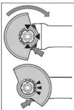
NoJXte 3aunTHbIK Kx (11) Ha KpeIeHne Ha 3JeKTPoHCTpyMeHTe TaK, 4To6bl KoNpyUOme KyauKN 3aunTHoro Koxyxa COOTBCTBOBn KpENHeIO. Pn3TOM HAKMITE n depKHTe HaxatbIM pbur pa3-6IoKHPOBKN (1). HadaBnBaHa 3aunTHbIK Koxy (11), HaDeHbTe ero Ha WeyKy WmHdienr TaK, 4To6bl 6byTK 3aunTHoro Koxyxa cen Ha fnaheC 3JeKTPoHCTpyMeHTa, n NO
BopaHbAte 3aunTHbI KOKxN, NOKa OH He BOJTe OTeTINBO B3auenHe.
OtperynpyTe noIOxKeHn 3aunTHoro koxyxa (11) B coOTBcTbHN C Tpe6oBaHnMn pa6oery npouceca.ДЯ STOrOpNkMTE pbyar pa36NoKpOBKn (1) BBepx NOBepHnTe 3aunTHbIKoKyx (11) B Tpe6yEmoe noIOxKeHne.
YcTaHabnBaHte 3aunTHbI KoxyX (11) Bcerda TaKIM 6pa30m, yTo6bI BCE 3 KpaChbIX KyaNaKa pbUra pa3- 6NoKpOBKn (1) 3aunN B COOTBCTByOuNHe OTBepCTHn 3aunTHoro Koxyxa (11).
YctaHabnBaIte 3auHTbI KOxy (11) taKHM o6pa30M, yTO6bl OH npedOTBpaan nonet NcKp B HAnpaBHeHH NOnb3OBATeJI.
3aunthbkoxyx(11)doJnHex nobopauHbTaBcTOnbKO pnp npHBeEHN B deHCTBne pbuara pa36KnPOBKN(1)!B npoTHBM cnyae npoDOnXaTB pa60Ty C 3NEKTPONHCTpyMeHTOM HEnb3,ero Heo6xoHMoOTDaTB CepBHCyIO MaTepckyIO.
Yka3aHHe:KOpnyUOHe KynauKn Ha 3aunTHOM KoxyXe (11) npDeOTBpaAaHT Bo3MOXHOCTb MOHTaKa Ha 3neKTpNueckn HnCTpyMeHT He npDeYCMOTpeHHbIX dIra Hero 3aunTHbIX KoxyXOB.
3aunTHbIKoKxDnpe3KN
- Pnpe3Kn c nOmoBIO Otp3HbIX KpyroB BCerda Hcnonb3yIe 3aunTHbI KOxydne pe3Kn (16).
Ipaep3KnKaMnHHeo6xOaHMo oecneHTb DocTaTOuHOe ydaJeHne nbIn.
3aunTHbIKoKxyDnpe3KN(16)MOHTnpyETcTaKKe,KaN 3aunTHbIKoKxyDnWnHPOBaHH(11).
3aHTbIKoKxyDnpe3Kn cHa npabnouMMn Cana3kAMN
3aunTHbIKoKxyDnpe3KNcHnpanBnIOuMNcana3kAMN (30)MOHTpyETCAkXe,KAKN3aunTHbIKoKxyDnIaNN- foBaAHn(11).
DononHntenbHa npKoAra
Pa6oTaIe C 3JIeKTPOnHCTpyMeHTOM TOnbKO c DonONHHTenBHOH pyKoTko (10).
PnHBHTNE DOnONHHTeNBHyO pyKoTky (10) CnpBa Hnn CneBa O TpeyKTOpHO rONOBKN B 3aBNCMOCTN OT CnOCob pa60tbl.
Bn6poracuaa dononHntbna pykortka

Bn6poracaa donolHntbna pykortka yMehbaaetypobenb Bn6paunncnocecneuBaetTM 60nee
KOMΦOPTHyU pa60Ty.
Hnyeo He MeHaIe BdoonHntbHo pyKoTKe.
He nonb3yTeCb NOBpeXeHHOI DOnONHTenbHOI pykoTko.
3aunTHbI uHTOK pyKn
Длpa60tpe3HHOBWuHΦOaBbHOHTapeNkoI (21),uaeHHOHIMDCKOBOWETKOHNBeepHBIM WnHΦOaBbHbIM KpyROMyCTaHaBnBaIte3aUHTbIuHTOKdpyKn (20).
3aKpennnTe 3aunTHbI uHTOK (20)DOnONHITeBHOpyKO-RTKO(10).
MOHTAXIINHFOBaIbHOH OCHACTK
Do hauana pa60 no Texo6cnyxHBaHIO, CmeHe HNCTpyMeHaTn.Д., a TAKKe npu TpaHcnpOpTHPOBKe H XpaHENH N3BNEkaTe AKKyMnyTop H3 3NeK-TPOHCTpyMeHa.TpHn HENpeHnAmepeHHOM BKNIOueHHN BO3HnKaET ONaCHOCTb TpaBMnPOBaHn.
He npHKacaiTecb K IINHFOBaIbHbIM HOTpe3HbIM Kpyram, noka OHN HE OCTbIHyt. Kpyr cInbHO HarpeBaHOTcBO Bpemra60tbl.
OuCTHTe ⅢHIOBAbHbI ⅢINHDeIb (19) N BCE MOHTnpyeMbIe Detann.
ДяЗakpenHЯИOTNYCKAHNAHUNΦOBAHOBHOOCHACTKN HAKMITE KHNKHyФNKcauNNUHINHDA(3),HTObby3aΦHKNPOBaTbNnΦOBaHbHbIMINHIDeB.
HaxnmaTe Ha KhoNkY fKcaunu uHHdner TOnbKn npn ocTaHOBHeHOM uHHdene! B npoTHBOM cnyuae 3NeKTPOINHCTpyMeHT MoKet 6bTb NobpeXdien.
UHΦOBaBbHbKpyr/otpe3HoKpyr
PnHmTE BO BHMaHHe pa3MepebluNFOBaHOB OCHAcTKn. DnAmeTp nocaDOHOro OTBepCTn DOJKeH COOTBeCTBOBaTB onOpHOMy fnaHcy.He npHmEHaTe aanTepb HnnpexOHNK.
PnHcNlB3OBAHnAIma3HbIX OTe3HbIX KpyROB CneIeHTe 3a TEM, UTo6bl CTpeNkA HApBaNHeH BpaUeHn Ha aIma3HOM OTpe3HOM KpyrHa HApBaNHeH BpaUeHn 3JekTPOHNCTpyMeHtA (CM. CTpeNkY HApBaNHeH BpaUeHn Ha peDyKTopHO rONoBKe) COBnadaHn.
IocneIOBaTeBbHcTbMOHTaKa NOKa3aHa Ha cTpaHnue CnNIOCTpaUAMN.
YtO6bI 3aKpENITb 7HnHPOBaNbHbI/OTpe3HO Knpy, HcNoB 3yTe 6bICP03aXmMHyrAky (14) 6e3 KaKnx-Nn6o HnCTpy MEHTOB.
IcnoJb3yIte 6bIcTpo3aXMHHyOraKy (14)TOnbKO dna WInfoBaJIbHbIX/OTpe3HbIX KpyroB dAmetPOM He 60one 150 MM.
260|Pycckn
BbIcTpo3aXHHMHyIOraKy(14)pa3peWaeTcHcNoIb-3OBaTb TOnbKOДЯ WINΦOBAhBbIX N OTPe3HbIX Kpy-ROB.
Mcnonb3yIe ToJIbKO HcnpaBHyIO, HENOBpeKdEHHyO 6bIcTpo3aXmHMyIOraKy (14).
PnHabHHuBaHH CneHTe 3aTeM, YTO6bI CTOpHa 6bICToPO3aXHMHO rAKnC HAdNcBIO (14) He 6bIna 06paueHa K WlnΦoBaHbOMy Kpyr.
ДдзakpenenneHnHFOBaIbHbIX/OTpe3HbIXKpyRO HcnoIb3yTe HckIOHTeBHO npHnaIauOuyoc6 bI- cTpo3aXHMHyo raKy (14).
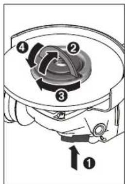
Длгфнсрованьшп ФОВАБНОТошИнDEЯHA ЖМNTE KHOПКУ ФнСРОВА HишИнDEЯ(3).ЧTOБ; 3aTЯHTb 6bICTP03aKHMHyO raHKY(14),NOHIMNTE cKO6y 6bICTP03aKHMHOI raHKBEPX H cYCNHEM NOBOPaUNBaTe 6bICTP03a KHMHYO raHKNo YACOBO CTpeKe.3aTeM onyCTHtE cKO6y 6bICTP03aKHMHOI raHKnДлгфнсровань 6bICTP03aKHMHOI RAHK. 3aTЯRBAHHe 3a 06oD,ДHC
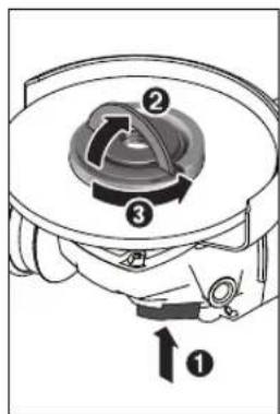
Ka He ABJIaTeCg DOCTaTOHbIM.
PpabHbHO 3aTnHYa, He NoBpeXeHHa86bCTpo3a XHMHraKa(14) OTNyc Kaetc pyKo. DnA 3TO NOHNMHTe CkO6y 6bCTPO 3aXMHOr RaKN BBepx H NOBepHHe 6bCTPO3aXMH HyIO rAky C CnNOI pNOTHB AACOBI CTpeKN. HIKoRda He pImMeHrte DnI OTKpy YBaHn3aKlHHBWe Bbl CTPO3aXMHOr RaKN HCHPTyMENT, oB3aTeBHO HCNoB3yIte POKKOBbl KNOU Nd DBA OTBepCTNa. Iocne MoTAXa OnOpHoro ФlaHua N WlnHFOBaNbHORO/ OTpe3Horo Kpyra DnHa CBO6DHOH Pe3b6bl WnH FOBaHbHO WnHDeIa DOJXHa CoCTABnTb He Me Hee 4MM.
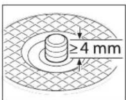
CneHte 3a npouHcTbOpymeHa,TO6bI OH He OTKpye 3NEKTPoHnCTpymeHa.
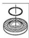
Ha onopnom fnahe (12) BOKpyr ceHTnpnyo 8ero 6yptnka haxoHntc nlaactMaccOBaJe TaJIb (KolbuO kpyrIoro CEeHn).EcnN KOnb- 40 KpyrIoro CEeHn OTCYCTByET HnnoBpeXdeno, onOpHbI nnneu (12) Heo6xOHN
MO63aTeBHO 3aMeHHTb nepeI dIaIbHeIIM PIPMHeHEm.
Pocne MOHTaKa WnHFOBaNbHOrO HnCTpyMeNTa npoBepTe nepeB BKnHoueHem nPaBnHbHOctb MoTAtKa H CBO6OHDoe BpaueHne HnCTpyMeNTa. PpOBepTe CBO6OHDoe BpaueHne WnHFOBaNbHOrO HnCTpyMeNTa 6e3 TpeHHo 03aunTHbIKoKxHnDpyHe qactH.
BeehblnHFOBaNbHbKpyr
PpaobT CBeepbHIM UHHFOBaBnBbHIM Kpyrom BceRda yctahabnBaHTe 3aunTHbHm TtOK dnn pykn (20).
Pe3HHOBaI WnHFOBaIbHaI TapeIka
Дяразбсpe3HHOBишнфовьаньhoeТарелков (21) bcerda yctaHaBnBaIte 3aunTHbI uHTOK dny pkyk(20).
IocneObaTeIbHOCTb MOHTaKa NOKa3aHa Ha CtpaHnue CnIIOCTpaIaMn.
Haenebtepe3HOByIO wHFOBaIbHyIO TaepKy (21) Ha wHFOBaIbHi bWnHdJIb (19).
PnKMMte uHNOBaNHyu KHNKHe CTOpOHe peHHBOOnOpHOu HNOBaNHOu TapeKN (21).
HaKpyTHe KpyrIyO raiKy (23) 3aTHnTe ee C nOMoUbHO pOKOBOrO KIOUc NOD Dba OTBepCTH.
aWeuHaJeTka/DnckOBaJeTka
Дярбсчшчнйштконинднckoboiштков BCERda yctahabnbaHTe 3aunTHbI uHTOKdЯpykn (20).
IocneIOBaTeJIbHOCTb MOHTaKa IOKa3aHa Ha CTpaHnue CIIIOCTpauHmN.
HaueHaa/tnckOBaIeTKaDnKHa HABHHBaTbca Ha 1nnHdNtak,4TO6bl OHa IIOTHo Ppnerana K pnaHcy 1nnHdN B KOHepe3b6bl WnHdN. Kpenko 3aTnHte 1wneHyO/DnCKOByIOeTKBnOuHbIM faeyhBMKnIOOM.
TbePocnnaBHyb yaeuHbI uHFOBaNbHykpy
HcnoB3OBaHne qaueHoro uHFOBaBbHOrO kpya DONYCKAeTc TOnbKO BmecTe C COOTBeTCTByIOHM 3a- HTHbIM KOKyXOM.
DonyctHMaI WnHFOBaNbHaA OChactka
KnpmeneHHoDnyckaOTcBce BnblnHpObaHoh OChactKN, ykaahHeB HactoIe pykoBoCTBe No 3KcNpy-atau.
DonyctHMOE uHcNo O6OpOToB [MnH-] HnN OKpyKna CkOPOCTb [M/c] npHMehRoMoI IINIOBOaBHO OHCACTKN DOnKHBn NO KpaHHe Mepe COOTBeCTBOBaT daHHbIM N3 CneHyoUe TaBnUb.
Co6nOaIteDOnyctmoeUcNoO6OpOToB HnKpyxHyOckopocb,yKa3aHHbIe Ha 3TNKeTke UHnΦoBaJIbHOIOChAcTKN.
| MaKC. [MM] [MM] | ||||
| D b d [MHH] | 31] [M/c] | |||
| 100 | 7 | 16 | 9000 | 80 |
| 115 | 7 | 22,2 | 9000 | 80 |
| MaKc. [MM] [MM] | ||||
| D b d [MнH] | 1) [M/c] | |||
| 125 | 7 | 22,2 | 9000 | 80 |
| 150 | 7 | 22,2 | 7500 | 80 |
| 100 | - | - | 9000 | 80 |
| 115 | - | - | 9000 | 80 |
| 125 | - | - | 9000 | 80 |
| 150 | - | - | 7500 | 80 |
| 75 30 M 14 9000 45 | ||||
| 82 - M 14 9000 80 | ||||
TobopaunBaHne peyKtopHOnrOOBKN (GWS 18V-10 C)
До hayana pa6ot no TextobnyxHBaHIO, CmeHe HNCTpyMeHTa N.T.D., a TAKKe npn TpaHCnoPTnPOBKe HxaHEHN N3BNeKaTe aKKyMnyTOp H3NeK- TpOHnCTpyMeHTa. Пи HepeDHaMEpeHHom BkIoueHIN BO3HnKaET OnaCHOCTb TpaBMPOBaHn.
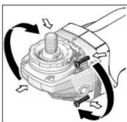
PepyKtopHnra rOIOBka MoKcT NOBOPaUHbTaC HHTepBaONM B 90°.3TNMBblKlNUoateNBMOeKt6bITNoCTaBHe B yDIOHoe dIpa60bI NOIOKeHne, HApnHMeP, dNNEBHN.
IIOHOCTbIO BbIKpyTHe 4 BNHTa. OToPOxHO H6e3 OTpbBaOt KOpNyCaNo
BepHnTe peyKtopHyro roNOBky B HOBoe noOKeHne. ChOba TyTO 3aTHnTe 4 BNHTa.
YdaneHne nbinnn ctpyckn
NbIbHEKOTopBxMATEpHaNoB,KaHnP.KpacOK C co- depKaHHeM CBnHcA,HEKOTopBx COPTOB DpeBeCInbI, MHepe pAOB H MetaIIIOB,MOXET BbT BpeDHOIN3DOPOBB. PnIKOCHOBEHNE K bIIN NnonaHne NbIN BDbxaTeNbHbIyTN MOXET Bb3BaTb aIepnueckne peaknn n/nn 3a6o- neBaHHa DbxATeNbHbIX nyTeonepatopa nn HaxOJaUeOrc B6nHn nepcoHana.
OnpeeneHbIe Bnbl nbHn, Hapn., ny6a n 6yka, cunTaTcA KaHuepoReHHbIMn, Oo6eHNo COBMeCTHO C pncadkm dInn o6paobtKn DpeBeCnHb (XPOMAT, CpeCTBO nI3aunbl DpeBecnbl). MaTePnAn C codepKaHaem ac6eCTa paapeWaeTcN 6pbabTBbAt Tohko CneuHaNTam.
-Xopoio npoBepnBaIe pa6ooye MeTo.
- PeKOMeHnyETcN nonb3ObaTbcra pecnnpaTophoMackoC cnbltpomKnaccaP2.
Co6nOaIte DeNCTByIOUme B BaWae cTpaHe npEINcaHna Ira o6pa6aTaBbAembix MaTePnaIOB.
M36eAte cKoJIeHn PbIIN Ha pa6OeM MecTe. IbIb MOKeT JERKO BOCIIaMeHrTcR.
Pa60Ta c HcHCTpymeHTOM
BkHIOueHenHe 3NEKTPoHnHcTpymeHa
YctahOBKaAkkymyIaTopa
BCTaBbTe 3apRaeHnbl aKKyMnyIaTOp (8) cnepeEn B HoxKky 3NeKtpoHHcTpymHa, YTo6bl aKKyMnyIaTOp HaedEKNHO 3aΦNK CnpoBaIcn.
BkIIOueHHe/BbIKIOueHHe
ДлгькючehнэлктponHCTpyMeHTa nepeBnHbTe BblKIOUATEJIb (6)Впeр.
IπaΦκcaHbBkHIOaTeH(6)nepeBnHbTe BkHIOaTeH(6)BnepeINBnH3Tak,YTObO HBOWenB3auENHe.
IyBbIKIOUeHN 3JNEKTPOINHCTPyMeHTa OTYCTNE BbIKIOuATenb (6) HnH,ecn OH 3aΦHKCPOBaH,HaxMMTE KOpTkoHa BbIKIOUaTeNb (6) Ha3ad N BHn3,a 3aTEM OTNCTNEERO.
IpeaHauanopapobtbpObepaTeunnoBbHyO ochactky. uHnfoBaHnaOchactka donxHa 6bTb npabNtboMOHTnpoBaHa H CBO6oHb Bpaatcbra. POn3BeHte np6hoe BKNIOueHne MHHyMaHa 1 MNHYe63Harpy3KH.He cNoIb3yHe NOpeXdeHHyo, HeKpyrnyHmN Bn6pnpuyuO uHnfoBaHbHyO ochactky. NOBpeXdHnA uHnfoBaHbHa OCHACTKa MoJcET pa3pyuHbCn CTaTb npuHHo TpaBM.
ChTeMa BbIKIOueHn npo6paTHOM yape

Pn HeoKnaHOM 6paTHOM yape 3neKTPoHnCTpyMeHTa, HAp.. PnBLOKNPOBaHH Bpa3pe3e, nOdaYa ToKa Ha DnRatEnb PpepbBaETc 3NEKTOPHKO. PnTOM CBToHOID NOCBETKn paOoeH 3OHbl (4) Mnraet BebM, a HH
ДИКаTOP COCTOHHN(35)-KpaCHbIM.
YtobcHOBaBKIOUHTb3eKTPoHCTpymENT,yCTaHOBNTe BkIOuATEb6)BNOIOXKeHHe BbIK.NCHOBaBKIOUHTe 3eKTPoHCTpymENT.
3aunta ot HenpeHaMepeHoro nycka
3aunitaOTHenpeHamepeHHoro 3anycka npedTbpaaaet HEKoHTpOHIpyembl 3anyck 3neKTPOHHCTpyMeHa Tocne nepe6oeB c3neKTPOCHabxehnEM.
PnAaTHBnPOBaHHo3aunTeOTHepeHamepeHHOrO 3ayncka HnHKaTOp COCTOHHN (35) Mrraet KpachbIM.
YtO6bI CHOBA BKJIOUHTb 3JIeKTPoHnCTpymEYT, yCTaHOBNTe BbIKIOuATeJIb (6) B NIOJOKeHHe BBIKI. H CHOBA BKJIOUHTe 3JIeKTPoHnCTpymEHT.
OTKIOUOHeHn npu ydape
BcTpoEHnCnTeMaOTKIOueHnIpn ydape BbIKIOaET 3NEKTponHCTpyMeHT, KaTToNbKO OHydpAeTcO6 NOI npn NaedHH. PpI 3OM HnDnKaTOp COCToHH (35) MHaET KpaChbIM. UTo6bl CHOBA BKNIOuHTb 3NEKTponHCTpyMeHT,
262|Pycckn
yCTaHOBnTe BbIKHouaTeIb (6)B NOIOXeHHe BbIKN. HCHOBa BKIOUHTe 3NEKTPoHCTpyMeH.
Tb3oBATEbcckn HHTepfeic (cm.pnc.D)
Pb3OBATEbcN HHTepcEc(5)CnyKNTnBb6opaHnaobopTOBnIINHnKauncoCTOHHa3NeKTPoHNCTpyMeHTa.
Bb6op qncna o6p0rOB (GWS 18V-10 SC)
C NOMOUIKHOIIKNBbIbopaYcNcnaOBOpOTOB(34)MOXHOyCTaHABINBaTbHeo6xOHNMOe YcNcNOOBOpOTOB BO BpEMpaBOTbl. DAnHHBe CNEUYIOUe TaBNIUE RBNIOCTpeKoMeHdyEmbIMn 3HaueHnMn.
Donycthmoe uHcno 06pOToB pa6oery HnCtpMeHa DOnJXHO 6bItb He MeHee yKa3aHHOro Ha 3NeK TPOHNCTpMeHTe MaKCHMaJIbHoro YHCna O6pOToB.
Pa6ouH HnCTpymENT, BpaauiouHcRc 60bnwe, yem DOnyCTHMO, CKOpocTbIO, MOKeT pa3OpBaTbcN pa3neTeTbCBA NPOCTpaHCTBe.
HdHKatOpbIcoToHHN
Iyom yctahOBKn OT 30o Do 40 npn 6npouHOM nnpoBAHn DOCTraOc HAnNyUwne pe3yNbTaTb pa6Otbl.BoIte 3NEKTPOHNCTpyMeHOM, cnerKa HxKMaHa Ha Hero, Tyda-cOJa. PnTakOM IOXOe o6pa6aTbBaemar 3aOTOBKa He 6ydet nepepeBaTcR, He n3MeHIT CBOero UbetaHa Ha Hn He HnoBBTcDopoxKe.
Beehbln mHnfoBaNbblkpyr
BeepbHIMIINFOBAIBHM Kpyrom (pNHHJNEKHOCTb) MOKHO TAKKe 06paBaTaIBaTb BbIyKnIbe NOBepxHOCTn I npOHN.
BeehIe IINFOBaHbIe KpyrN 6nlaIaOT3HaHTenBHO 60nbHM CPOKOM Cnyk6bl, CO3dAOT MeHbWu yPoBeHb WMy MHeBwne TEmnepatypbl IINFOBaHn, cem 6bUHbIe IINFOBaHbIe KpyrN.
Pe3Ka MetTanna
- Pnpe3Kc nomoBIO OTe3HbIX KpyroB Bcerda Hnonb3yIte 3aunTHbI KoKxyn Pn pe3Kn (16).
PnOTpe3aHHHINHFOBbHbIM KpyrO pa6oTaIe CymepHHo, COOTBeTCTByUeJe O6pa6aTBbAemOMy MaTeHany, NOaueH. He OKa3bBaIte DaBHeNe Ha OTpe3HOKpyr, He nepeKaUNBaIte Hc KaauIte erO.
He 3aTopMaXnBaIe OTpE3Hoi Kpy Ha BbIbe6OKOBIM daBneHnEM.
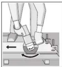
Bcerda BeDnTe 3neK TPOINHCTPymENT npOTNB HAnpabNeHn BpaUeHn. B npOTNBOM Cnyae CyIeCTByET ONaCHOCTb HeKOHTpONPiBOBaHHOro BblpbIBaHnIHCTpyMeHa n3 npope3n.
Pn pe3ke npofoinne nn nnybtpiexrgpaaHbX Tpy6 HaunhaTe pe3 Ha HAmMeHb
JEMIJIeHOMceEHN.
Pe3Ka KaMHa (cm.pHc.C)
Длpe3knKamHRe Heo6xOdHMo oBeceuHTb DocTaTOOHoe ydaene Hne nbinn.
PpHmEnaTe pOHTBOnbIeBOeBopeCnnpaTOp.
AnHHb3eKTPoHcTpyMeHT pa3peWaaetc HcNoB30BaTb TOnbKOdnyCxyo pe3KN/cyXoUuHfoBaHn.
264|Pycckn
IJIpe3KNKAMHEnIyUWeBCeroHCNoIb3OBAb aIma3HbEOTpe3HbIeNCKN.
Pn npmeneHH 3aunTHoro KOxya nIg OTpe3AHn C HnpaBnIOUHM caNA3KaMn (30) nb/ncoc dONKeH 6bTb DonyueH nIg OTCoca KaMeHH Nbl. Bosch npednaet NOxOJaNE Nbl/ncocbl.
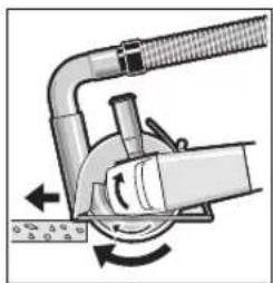
BkHIOHTe 3NEKTPoHNCTpyMeHT N PnCTaBtpe nepeHIOHOaCTb HnPaBIAIOUXcana3OK K 06pa6aTbIiBaemO 3aTOrOBke. BeInteNHEBMATNuEckn INCTpyMEHT CpaBHomePHO, paCCHTaHHo HA 06pa6aTbIaEBmy MaTePnaI Noaaye.
PnO6pa6oTkeoc6o
TBePbIX MaTePhaIOB, HAnpIMep, 6ToHa C BvICOKM CoepKJaHHe rpaBnA, aIma3HbI OTpE3HO Kpy MokET nepePrtbCn I No 3ToI npUHne NOBpeDHTbC. BpaiaIoUncsca aIma3HbIM OTpE3HbIM KpyROM BENEu N3 NCKp OJHO3HaHoYkAsbBaet Ha TaKyIO CTyauio.
B Takom cnyuae npepbnte npouecn daiTe anmaHomy Ope3HOMy Kpyry octbIb Ha XOIOCTOM XOy npi MaKcHMaJIbHOH CKOPoCTN B TeueHne KOpOTKOTo BPemEH.
3aMeTHOE CHKHeHne pOnn3BOJHTenbHOCT naBoTn BBeue H3 NCKP NO KpyrCyBnDETeNbCTBYIOT O 3aTyIeHN AnMa3HO To Tpe3HOrO Kpyra.Am3HbN OTpe3HO KnpyrMOxHO 3aToHtB KopoTKHM pe3Amn Babpa3HBom MaTePhane (HaNP., B CnHKaTHOM KHPnue).
Yka3aHnnoCTaTHKe
Ha na3bI B KANITaNbHbIX CTeHax pacnpoCtpaHraTc HOpMa DIN 1053 cactb 1 nn DeiCTByIOUe B COOTBETCTByIOUe CTpaHnePpeNHCAnH. 3TN PpeNHCAnH NoDnEkaT o63aTeNBHOmy Co6NIoDEHHIO. Do hauana pa60tbi npOKOHcybTHpyntecb y OTBETCTBEHNO CneuaHNTa NO cTaHke, apxHTekTopa nn npop6a.
Yka3aHHNo ONTHMaHbHomy o6paueHHc aKKyMnyTOpOM
3aunuiTe akkymyIaTOp oBlaHn BObl.
XpaHnTe aKKyMnTOp TOnbKo B Dnana3OHe TemnepaTp O- 20^ Do 50°C. He octabnTe aKKymnTOp nToM B ABOMo6nne.
Bpemot Bpemn npounaHTe BEHNTIauHOHHbI pnpoe3n aKKyMnyTOpa MkKo, cyxO uNCTOKNCTOOKo.
3haHTbHoe cokpaueHHe npoDOnKHTeBHOCTn pa6Otbl nocne 3apra CBNTeBcTByet OCTapeHHN AKKMyIaTopa yka3bIaBET Ha He0xOINMOCTb Ero 3aMeHbI.
yUHTbIaBteYka3aHnnoYtINn3aunn.
Texo6cnyxHBaHne n cepBnC
Texo6cnyxHBaHne H ouhctka
Hauana pabot no Texo6cnyKBAHHIO, CmeHe HCTpyMeHTa T.Д., aTakke npn TpaHCnpTnPOBKe HxaHHeHH N3BNeKaTe aKKyMnyTOp H3 3neK
TpOHnCTpyMeHa.Пи HnpeHnHaMepeHHOM BKnHoueHHN BO3HNKaET OAnCHOCTb TpaBMnPOBaHHa.
Длбобсесенькачевнй 6e3oanchо pa60TbI coDEpKHTe 3NEKTPOHCTPymeH N BENTINHONHbI e npope3n B uCTOTE.
3a6oTnBxpaHnTe H o6paauTecb c npHaadJeKxHocTMy.
CepBn KOncynbTnpoBaHne no BOpocam npmeneHH
CepBnchbI OTen OTBeHT Ha BCE Baun BOpocbl no peMoNTy nObCyKbAHNo BaWero npOyKa, a TaXKe no 3anYactm. H3o6paKeHn CnpocTaHCTBeHHbIM pa3deneHnEMDenateHn HnFopMaHIO No 3aNuaCTM MoKHO NOCMTpeTb TAKKe no aDpecy: www.bosch-pt.com
KoNkTNB COTpyDnHKnOB Bosch, npedocTabnauu KOnCynbTaunn Ha npedmet nCnoJb30BaHnnpOyKUnn, C yDOBOJIbCTBNEM OTBeTHT Ha BCE BaUN BONpOcbl OTHOCNTbHO Horo Hae npOdyKUnn Ee npHnAaNEXKHOteN.
IpoKanyuCTa,BO BcEx 3anpocax H3akazax 3anuaCTe 06a3aTeBbO yKa3bBaIte 10-3HaHbI TOBApHbI HOpE p No 3aBODCKoT a6nueKe n3dien.
IpaHTHnHOe 0cbNyKBaHHe n peMOHT 3neKtpOnHCTpyMeHtA, c CobIOJeHNEM Tpe6oBaHn HOPM N3rTOBOTEnI npO1N3BOJ4Tc H TePPOTnBn Bcex CTpAn TOnBk BO pHmEHHbXnn ABTOP30BaHbIX cepBnCbIX ceTpax P6opept BoW. IPEyIPEXJEHE! NcOJIb3OBAHne KOHTpaKaTHoIpoDyKUnn OAnCHO B3KnnyatauNN, MoKet npNBecTN K yUep6By dBaBero 3dOpOBa. HArTOBNeHne n pacnpocTaPAHHe KOHTpaKaTHoI npOdyKUnn PpeCneYetyernc No 3aKohy B aMNHHCTpAHBM N yFONOBHM NOPdKe.
Pocchra
YIOnHOMOueHHa H3r0TobHTenem opraHn3auH: 000 «Po6epT BoW» BaUyTHnCKoe WcC, Bn.24 141400,r.XmMkn,MockOBckar o6n.
Ten.: +7 800 100 8007
E-Mail: info.powertools@ru.bosch.com www.bosch-pt.ru
Benapycb
INP06epT BOWO OOO
CepBnChbI ueHtp no 06cnyxHBaHIO 3NeKTPoHHCTpyMeHTa
yn.Tmnpa3eBa,65A-020
220035,r.MnHck
Ten.: +375 (17) 2547871
Ten.: +375 (17) 254 79 16
akc:+375(17)2547875
E-Mail: pt-service.by@bosch.com
OphiunalbHbI caHT: www.bosch-pt.by
Ka3axctan
LcHrP KOncyIbTnpoBaHHu npHeMa npTeH3N TOO «Po6epToBou» (Robert Bosch)
r.AmMAtbI,
Pecny6lnkaKa3axctan
050012
yn.Mypar6aeBa,180
BIL «Fepmc», 7ιətax
Ten.: +7 (727) 331 3100
_A C: + 7 (727) 2330787
E-Mail: ptka@bosch.com
POnHyIO nAKTyalbHyIO HhOpMaUO pAcnoIooHenH cepBnChbIX cHTPOB I pInembIX NyHKTOB Bbl MoKTe nOnyHtBa OHouuHaONaHbHOM caIe:
www.bosch-professional.kz
Mondoba
RIALTO-STUDIO S.R.L.
Пи. KaHTeMnpa 1, 3aXk 3, ToproBbI ueHrToTOIa3
2069 KniHnHeB
Te.n.: +373 22 840050/840054
ΦaKc: +37322840049
Email: info@rialto.md
ApMeHHA3ep6aJxHAn,py3nKpH3CTah,MoHroJIIN,TaXKNKCTAH,TypKeHHCTah
TOO «Робет Боч» (Robert Bosch)
Power Tools noclenpodaaknoe 6cbnykHBHne npocneKT
Paibim6eka 169/1
050050Anmatb,Ka3axCTaH
Cnyke6nae3n.nouta:service.pt.ka@bosch.com
OΦηιαλβήν Βe6-caɪT: www.bosch.com, www.bosch- pt.com
TpaHcnpTnpoBka
HaBNOKeHHbIe NHTHeBO-NOHHbIE aKKyMnTOpHbIe 6batape pacnOcTpaHHOTc Tpe60BaHHB OTHoUeHHN TpaHCnOpTHPOBKN OnaChbIX rpy3OB. AKkyMnTOpHbIe 6batape MoryT nepeBO3HTbcra CAMM IIOb3OBAteMe ABTOMo6uNbHbIM TpaHCnOpTOM 6e Heo6xOdmoCTn Co6IHOeHHaDOnONHTeJIbHbIX HOPM.
PnpeB03e C npBneueHem TpeBx Nius (HaNP::cAmOLeTOM HIN TpaHCnOpTbIM EKCTeHITOpOM) Heo6xOJIMOco6IoudaTb Ooc6Be Tpe6OBaHH K ynaKOBKe M MapKnPOBKe.
B 3TOM cnyuae npn noJroTOBKe rpy3a K OTnpaBKe Heo6xOmo yuaCTHe kCNEpTa nO anChbIM rpy3am.
OTnpabnIte aKymyIaTOpHy 6TaapeIO TOnbKO c HEnOBpeXJDeHHbIM Kopnycom.3aKeIe NTkpbItbe KOHTAKTbI yNAtKyIte aKymyIaTOpHy 6BaapeIO TaK, UTo6bI OHa He nepeMeUaIacb BHyTpH yNaKOBKn. IoxaLyIcTa, coBIoJaTe TaKke BO3MOxHbIe DOnONHtEhBHe HaNoHOHbHbIe npDnncAHHa.
yTnH3aun

3NeKtponHCTpyMeHTb, AKKyMnTOpHbIe 6atape, npHaJnEaXHoCTN yNaKOBky HxKHO cBaTaB Ha 3KnOIoRnueCcku NcTHy peKynepaunio.

He Bb6paBbAte 3neKtpoHcTpymeHTbN akKymyTOpHbIe 6batapeu/6bapeeKn B 6bITOBMycOp!
AkkymyIaTopb/6aTapeH:
JIHTH-NOHhbie:
PonkaanyIcTa, yunbIaIte yka3aHHe B pa3dene TpaHcnoptnPOBka (cm. "TpaHCnOpTHPOBka", CtpaHua 265).
YKpaIHcbka
Bka3iBkn 3Texhikn 6e3neKn
3arabhi 3actepexeHHn enektponpnaad
A PpoaTae Bc3acTepeXeHnI IPONEPEKHEHHB Kb3iBKn. HeOpTpMaHnHa 3actep
I BKA3IBOK MOKE npH3BecTH Do ypaKeHH eNEKTPnHMMCTpyMOM, NOXeKi Ta/a6o cepNo3HNx TpaBM.
D6pe 36epiraTe Ha MaH6yThc zi nonepeJKeHHa i BkA3iBKN.
PiD NOHRTAM eEeKTPoIHCTpyMeHT B UHX 3actepexehnX MaTbCA HA yBa3i eEeKTPoIHCTpyMeHT,IO npaioe BiD MepeKi (3 eEeKTPokaBem) a60 BI d AkymyIaTOHOIbataei (6e3 eneKTPokaBENIO).
(25) AnmaHa CBepeHnHb Ka KopoHa
(26) Khonka iHnkaTopa 3apxkehocti (GBA 18V...)
(27) INdkatop 3apAnkeHocti akymyIaTopHO6aataei (GBA 18V...)
(28) Khonka iHnkaTopa 3apJKeHocti (GBA 18B 6,3 A-rod., ProCORE18V...)
(29) INdkaTOp 3apAnJeHoHcTi akymyIaTOpHoi 6aTaapei (GBA 18B 6,3A-roi..ProCORE18V...) ^A)
(30) BNTJXHH KOBnK DnApo3pi3aHH 3 IIOHeTHM cynopTOM
(31) AIma3Hn BiDpi3Hn Kpy
(32) INHkaTOp 3apAJIeHoCTI akymyTApTOHoi 6aTaPei (IHTEpΦeIC KOpHCTByBaUa)
(33) INdkaTOp BCTaHOBNeHOI KINbKOcTi 6eptiB (InTepeHc KopnctyBaay)
(34) KhoNka BCTaHOBHeHHa KInbKocTi oBeptiB (IHTeppeic KopnctyBaay)
(35) INdkaTop cTany eNeKtpoiHCTpyMeHTa (iHTeppeKoPncTyBaay)
(36) IINKATOP 3axncty Bi npebaHTaXeHHA (iHTepfien KOpNCtBya)
A) 3o6paXeHe a6o Omncane npnndn He BXOHTb B CTAndaptHnOcHr NoCTaBKn. NOBHH acOpTHMeH nPnnaDn Bn 3haJeTe B hawin nporpamipnpnaJa.
Texhihi dahi
Kytoba uniΦmaunha GWS 18V-10 C GWS 18V-10 C GWS 18V-10 C
| Товарниnomер | 3 601 JG3 0.. 3 601 JG3 2.. 3 601 JG3 1.. | |||
| Hom. Hanpyra B= 18 18 18 | ||||
| Hominaьнak kinbikicb obeptrivxbvn. | 1 | 9000 | 9000 | |
| Kilbikcctb obeptriv ha xoloctoymxodyxbvn. | 1 | -- -- | ||
| Makc. diametpr shiifybalnhoro kpyra mm 100 115 125 | ||||
| Pizbba shiifybalnhoro shinndela M 10 M 14 M 14 | ||||
| Makc. doBXHHa pi3b6n shiifybalnhoro shinndela MM 22 22 22 | ||||
| BmKHeHnA pRn cInaHnI ● ● ● | ||||
| 3axHcT bID nobToHORO nyck y ● ● ● | ||||
| fALbmo iHerpuiHOro BV6iry | ● ● ● | |||
| BCTaHOBeHNHa KILbKOcTi o6eptiv | --- | |||
| Bara bIDnoBvIINO do EPTA-Procedure 01:2014 | ||||
| - 3doaTKBOIO BIBpo3axHCNO pykoHTKOIO | Kf | 2,6-2,8A) | 2,6-2,8A) | 2,6-2,8A) |
| - 3doaTKBOIO CTandapTHOу pkoTkoIO | Kf | 2,4-2,6A) | 2,4-2,6A) | 2,4-2,6A) |
| Доустma TempepaTyRa habKoIIshNoBo rcepeobuissa | ||||
| - pri zapadkaHni | °C | 0...+45 | 0...+45 | 0...+45 |
| - pri ekplnyataci" i pri zh6epirahni | °C | -20...+50 | -20...+50 | -20...+50 |
| Pekomendobani akumylantopnI 6batapei | GBA 18V... | GBA 18V... | GBA 18V... | |
| GBA 18V...W | GBA 18V...W | GBA 18V...W | ||
| ProCORE18V... | ProCORE18V... | ProCORE18V... | ||
| Pekomendobani zapadni priNcTPOi | AL 18.. | AL 18.. | AL 18.. | |
| GAL 3680... | GAL 3680... | GAL 3680... | ||
| pekomendobani zapadni priNcTPOi IndyukTBHnx akumylantopnIX 6batapei | GAL 18W... | GAL 18W... | GAL 18W... | |
| Ipepea daHnX | ||||
| Bluetooth* | Bluetooth*4.2(3 HN3bKHM eheprocnoxHBANH RA)C) | Bluetooth*4.2(3 HN3bKHM eheprocnoxHBANH RA)C) | Bluetooth*4.2(3 HN3bKHM eheprocnoxHBANH RA)C) | |
| Itepbal cnHany | c 888 | |||
| maksimailha danbHcTb cnHanyD | m 30 30 30 | |||
| A)ВзалжноTi BiD викорисовуаноi akumулатoprohoi 6batapei | ||||
| B)обменияnotuyнICTb pri TmpepaTypi<0°C | ||||
| C)Мobilны Терminалы IOBHHI Bytnc cymich 3 priNcTporAMS Bluteoth 3 HN3bKHM eheprocnoxHBANHAM (Bercia 4.2) i NOBHHI niDTPmByBatn ctaHdpart Generic Access Profile (GAP). | ||||
| D)Далбпсь сгнану мосяЗачно BiDriZHATNCS BzalexHocSti BiD зовишixу mOB, ВКLOUaOuHi BinkorcisToBvBani priMauChi. ВсередипЗakrtnix priMiiuehBi Kp3b MeTaNBeI nepezkodn (Hanp., CTIN, PONJI, QOxNI ToTO) dablHcTb priOxodJeHNA CnHany Bluteoth® мосяЗачно ScKoPouYBaNTCb. | ||||
| Kytoba shiifmaHnha | GWS 18V-10 SC | GWS 18V-10 SC | GWS 18V-10 SC | GWS 18V-10 SC |
| TobarHni homer | 3 601 JG3 3.. | 3 601 JG3 6.. | 3 601 JG3 4.. | 3 601 JG3 5.. |
| Hom. Hanpyra | B= 18 | 18 18 | 18 | |
| Hominaьнak kinbikicb obeptriv | XBnL.1 | 9000 | 9000 | 7500 |
272|YkpaHcbKa
| Кутombaшліфмаша GWS 18V-10 | GWS 18V-10 | GWS 18V-10 | GWS 18V-10 | ||
| SC | SC | SC | SC | ||
| Кількісті оберіві на{x\'о\'oc'tomuyx\'odyxbn}. | 4500-9000 | 4500-9000 | 4500-9000 | 4000-7500 | |
| Мамс.Дiamетршідіфьально кругamaM100115125150 | |||||
| Різьбішідіфьальношпін'dелmaM10M14M14M14 | |||||
| Мамс.Довжіna різьбішідіфьальношпін'delma | MM22222222 | ||||
| Вимкині пісініні ●●●● | |||||
| Зхіnt Bіd NOВТOPНО рUCY ●●●● | |||||
| Галь мін\'еціні РБібігУ ●●●● | |||||
| Встановіні кіль\'ьості оберів ●●●● | |||||
| Bara Bіnd\'OBiDno do EPTA-Procedure 01:2014 | |||||
| -3do\'atko\'ою Bi\'rozo\'ax\'ch\'o\nyk\'o\'TKOIO | \( {Kr} \)2,6-2,8 | \( ^{A)} \) | \( 2,6-2,8^{A)} \) | \( 2,6-2,8^{A)} \) | \( 2,6-2,8^{A)} \) |
| -3do\'atko\'ою CTan\'d\r'THNO\nyk\'o\'TKOIO | \( {Kr} \)2,4-2,6 | \( ^{A)} \) | \( 2,4-2,6^{A)} \) | \( 2,4-2,6^{A)} \) | \( 2,5-2,7^{A)} \) |
| Д\'опuctima tem\'peratypa hab\'koli\'sh\"hbofo cepe\'ob\nuia | |||||
| - pri\'za\'d\'kAnhino | \( {^\circ C} \) | 0...+45 | 0...+45 | 0...+45 | 0...+45 |
| - pri\'ek\'pIyataciü‘i pri\'ne 3\'e\rɪganhi | \( {^\circ C} \) | -20...+50 | -20...+50 | -20...+50 | -20...+50 |
| РекOMe\'d\'obani akum\'yЯл\'topи 6baapei | GBA 18V... | GBA 18V... | GBA 18V... | GBA 18V... | |
| GBA 18V...W | GBA 18V...W | GBA 18V...W | GBA 18V...W | ||
| ProCORE18V... | ProCORE18V... | ProCORE18V... | ProCORE18V... | ||
| РекOMe\'d\'obani з\'ar\'dni pri\'st\r\'oi | AL 18.. | AL 18.. | AL 18.. | AL 18.. | |
| GAL 3680... | GAL 3680... | GAL 3680... | GAL 3680... | ||
| pekOMe\'d\'obani з\'ar\'dni pri\'st\r\'oi\'dlya iNDykTbHnx akum\'yЯл\'topnix 6baapei | GAL 18W... | GAL 18W... | GAL 18W... | GAL 18W... | |
| П\'е\'ed\'a\'d\'anx | |||||
| Bluetooth* | Bluetooth*4.2(3 HN3bKIMehe\r'ocno\'KbNaHNRM)\(^{C)}\) | Bluetooth*4.2(3 HN3bKIMehe\r'ocno\'KbNaHNRM)\(^{C)}\) | Bluetooth*4.2(3 HN3bKIMehe\r'ocno\'KbNaHNRM)\(^{C)}\) | Bluetooth*4.2(3 HN3bKIMehe\r'ocno\'KbNaHNRM)\(^{C)}\) | |
| IInte\'ba nCtg'Hany | c8 | 8 | 8 | 8 | |
| Мak\'ch\'m\'alha д\'alb\'h\'ictb с\'rig'Hany\(^{D)}\) | M30303030 | ||||
A) B 3anexkhocti BiD BNKOpHCTOByBaHOI ayKMyIaTOpHOI 6atapei
B) 06mexha notykhictb npntemnepaTypi < 0^
C) Mobinbhi Tepminn noBHHH 6yTH cymich3 npctpoaBlteoth 3 Hn3bkM eheprocoXnBaHHAM (Bepci4.2) i nobHHH niTpMyBat nCTanapt Generic Access Profile (GAP).
D) DnBHCtB CnHany MoKe 3HaHNO BIDpi3HrTcN B3aNeKHOCTi BID 3OBHIHX yMOB, BKIOauOu BNKOpHCTobyAHI npmuai. BcepeHH 3aKpHTx npMIueHb i KPI3b MetaneBI nepeXKOu (Hanp., CTIN, NOnu, OOnN TOU) DaNBHCtB npoxOJxEHn CnHany Bluteoth moKe 3HaHNO CKOPoYBaTHCb.
Infopmaia 7o0o 7ymy i bi6paa
| GWS 18V-10 C GWS 18V-10 C GWS 18V-10 C | |||
| 3601 JG3 0.. | 3601 JG3 2.. | 3601 JG3 1.. | |
| Ровеньшимов Визанецни Вдповidi这样做 EN 60745-2-3. | |||
| A-звашени ровень звуково тиски вд пhevваиматчно истру金融市场, як правлио, стаховить | |||
| Ровень звуково тиски дБ(A) | 79 | 79 | 79 |
160992A4B1|(09.05.2018) Bosch Power Tools
| ah | M/C2 | 6,0 | 6,0 | 6,0 | 6,5 |
| K | M/C3 | 1,5 | 1,5 | 1,5 | 1,5 |
ShiΦyBaHnHa6pa3nBHOUo 8Kpyko:
| \( a_h \) | \( M/c^2 \) | 3,5 | 3,5 | 3,5 | 3,0 |
| K | \( M/c^2 \) | 1,5 | 1,5 | 1,5 | 1,5 |
3aahueHn Buxkax bkaizkax pibehb BiopauiBmipioBaBC 3a HOpMOBaHOIO npOeDpyoO,OTKe Hm MOxHa KOpCTyBaTHCnI IIN oPiBHHN eNEKTOIHCTpyMeHTIB.BIN npDaTHn TaKoX iI IN nonepdHboi OUHKn BiopaunHoro HabaHTaKeHH.
3a3haeHHPiBHeB Bi6paui CTOcyTcBcraIIOBHNx po6it,
JRAHX 3actocobyCTCBAEIEKTPponpnaI. Ondak npn
3actocyBaHNI eNEKTPponpnaIy DnA IHUHx PO6i, p6oTI 3
IHUMPOOChMn IHCTPmENTAm a60 npn HeNOCTaTHbOMy
TexHCHOMY 6cnlyROByBaHHi PiBHe Bbiapui MoKe 6yTH
IHUM.Bpe3yIbTaI Bi6paui He HabaHTaeHHN POTAROM
BCbOrHO INTEpBaNY BHKOPNTaHHI IHCTPymETy MOKe 3HaCHO
3poCTAH.
ДяTOUHoiOUIHKN BIBpauiHoro HabaHTaKeHH Tpe6aBpaXOByBaTHaTakOx i INTEpBaINu cacy, KOJI npIauBIMKHyTN a6o, xOuyiYbIMKHyTN, ane camE He Bpo6oti. LcMOKE 3HaUHO 3MeHUnTI BIBpauiHHe HabaHTaKeHHnpOTROM BCBOrIO INTEpBany BIKOPnCTaHH npIauNy.
Bn3haTe DoaTkObi 3axoDi 6e3neKn Dn3aXnCTy onepatopa enektpoiHcTpymeta BID BiBipauu, Hanp.:
Texuhe 0cbnyoBvBaHHe enektpoiHcTpymeHaipobounx IHCTpymeTIB, HarpibaHpyk, oprahiaucipobounx npocecib.
MOHTAXK
BctaHOBNEHMAOyNA Bluetooth Low Energy Module GCY 30-4
BkaibKa: nene eneKtpoiHCTpyMeHTIB GWS 18V-10 C Moynb Bluetooth Low Energy Module GCY 30-4octynn B Akocti npnaa; nene eneKtpoiHCTpyMeHTIB GWS 18V-10 SC bih BXoHb B KOMNNEKT NOCTABKN.
Ipy OPMHn HINOPMaui 10oMoynuBleoth Low Energy Module GCY 30-4 npouHTae BiNobiHy IcTpykuio 3 ekcnnyataui.
3apdkaHnAkyMnyaTOpHo6atapei
KopnctyntecnHmze3apdHmnpnctpoaM,0 npenepeniehi ha ctopiui 3 npnaqam. Hne Ha ci
274|YkpaHcbKa
3apnHpiPnCTpoi po3paxoBaHn nIitEBo-ioHHn akMyTApOp, 10BnKopnCTOByetbCny BaWoMy npnadi.
Bka3iBa: AkymyIaTOpHa 6aTape nocTaaCb8 CaCTKOBO 3apJKeHOIO. Lio6 akymyIaTOp mir peaIizyBaTH CBOIO NOBHy cMHiCTb, nepeT TmH, kN nepuHn pa3 npauOBaTH 3 npnaDOM, akymyIaTOp Tpe6a NobHcTIO 3apJdHTn y 3apAHOmy pInctPoI.
IitcBc-0HnnakymyTrop MoKHa 3apKaTu KOJI 3aBROHO,ue He cKopOyuE Ioro ekCnnyatauHHn pecypc. IpeepBaHH npouecy 3apJkaHH He nookDjye akymyTrop.
IitieBO-ioHHn akymyIaTOp 3axHneHHn BID rH6OKoR0
po3pJxKaHHn CnTeMoIO „Electronic Cell Protection" (ECP).
Pn pO3pJxKeHOMy akymyIaTOpi npnau3abKn cxeml
3axHcyBmNkAcTbCn. Poobou n HcTpymeht 6ilbne He pyxaTbcn.
Picra ABOMTHHOROBHMKAHNEEeKtpoHCTpyMeHa6InBe He HATCKyTe Ha
BMMKau. Ye MoKe NIOuKOINH aKyMyIaTOpHy 6aTapeo. 3BaKaIte Ha Bka3iBKN IooD O BuaIaENHr.
BnMaHnaakymyIaTopa
Bakymyntopi (8) nepe6aehi DBA CTyneni 6nokybaHH, nOKNIKAHI 3anobirn BnadinHIO akymyntopa npn HEHaBMCHOMy HATNCKAHHI HA KHONKY po36nOKyBaHH akymyntopa (9). BCTpOMIeHBI EeneKTPoPnPnad akymyntop TPhMaTcBcY I NOLOKeHH 3ABJKN pnyHHI.

IooB BHTTN akymyTnTOPHy 6atapeo (8) HaNTCHITb H KhoNk y po36nOKyBaHH (9) Ta BHTARHtB akymyTnTOPHy 6atapeo 3 eNEKtpoiHCTpyMeHa, NotaHbwn II BnpeD. He 3actocobYte npu bomy cnny.
IIndkaTop 3apdxKeHocTi akymyIaTOpHOI 6aTapei (TNn akymyIaTOpHOI 6aTaapei GBA 18V...) (INB. Man. A)
Tpni 3enei CBITIOIOIN INHKAtopa cTany 3apny (27) BiO6paKaHOb CTAN 3apny akyMnyTOPOHbATEe (8).3 MIPkyBaHb TexHikn Be3neKn ONITyBaTH CTAN 3apxJKeHOCTI akyMnyTOPAO MOXHa NIIe PnP 3ynHeHOMy enkTpoIHcTpyMeHTI.
HaTCHITb KHONky (26), 106 BiO6pa3HTcTynHb 3apJxekHOCTi. Lc MoXHa 3po6HTn i TOni, KOnn aKymyIaTOPha 6atape8 (8) BNTrHyTa 3 eneKTpoinCTpyMeHTa.
Cbitnoiod EMHictb
CbueHHa3-x3eHnHex2/3
CbitnoioEhnicb
CbivHn2-x3eJeHnx≥1/3
CbiueHHa 1-ro 3eneHoro < 1/3
MiraHnHa1-ro3eIeHOro pe3epB
KJIO nicnHaNTCKAHHa KHONKY (26) He CBITNbCJ KOHN CBITNOIOD, aKymyIaTOp BmIoB 3 naNy i Noro TpeBa3AmHHTN.
Bka3iBa:3apJxHeHCTb akymyTTOphO6batapei BIO6paKaacTaKoX Ha moyni IHTepFeCy KOpNCTyBaHa (5) (INB. IHTePFeC KOpNCTyBaA (INB. Man. D), CToPiHa 278).
IHHKATOP 3apAIXeHOCTi akymyIaTOPOHoi 6atapei (TIN akymyIaTOPOHoi 6atapei GBA 18B 6,3A-rod., ProCORE 18V...) (nB. man. B)
I'Yb 3eEHn CbitnoiOIB IHnKaTOpa 3apJxHeoCTI akymyIaTOpHO6Baapei (29) BiIO6paKaIoTB CTah 3apJNy akymyIaTOpHO6Baapei. 3 MIPkyBaHb TexhIKn 6e3neKn ONHTyBaTH cTaN 3apJxHeoCTI akymyIaTOpMoKHa IInWe npN 3yINHeHOMy eNEKTpoHcTpMeHTI.
HaHCHiB KHONKy (28), 06 BiO6pa3HTN CTynIHb 3apJxekHOcti. Lc MoXHa 3po6HTn i Todi, KOHN akymyIaTOPHa 6atape BHTaHyta 3 eNEKTPOINCTpyMeHTa.
CbitnoioEhnicb
CbueHH53eneHx>80-100%
CbivcHH43eneHx>60-≤80%
CbueHHH3-x3eneHHx>40-≤60%
CbueHHH 2-x 3eneHHx>20-≤40%
CbueHHH1-ro3eHeHoro >0 - ≤ 20%
MuraHH1-ro3eneHoro0%
KIO nicnHaTNCaHnHa KHOIky (28) He CBITbCJ KOHN CBIITNOiO, aKymyIaTOp BmIoB 3 naNy i I Noro Tpe6a 3amIHNTN.
Bka3iBa:3apJxKeHCTb akymyTropHo6batapei BIO6paKaAeTcra TAKoX HaMoyni IInTepeCy KOpNCTyBaHa (5) (INB. IHTepeC KOpNCTyBaA (INB. Man. D), CToPiKa 278).
MOnTaK 3axHcHnx npctpoB
Ipeyicma MaHinnynuaM3 eNKTPOHCTPymeHTOM (HAP.,TexHINHM O6cnyROByBaHHM,3aMIHO p06oHOrIO HCTPymeHTA TOO),aTAKOX npH NORo TpaHCNOPTyBaHHi 36epirAHHI BmMaHTe akymyTOpHy 6atapeo 3 eNKTPOHCTPymeHTy. Pn HEBAMCHOMY BKJIOUeHHI BMMKaay icHy eHe63neka IopaHEHH.
Bka3iBaK: Pnnoonomkn 1nifybaIbHoro kpyra nid cac po6oTn a6 npn noNkoJKeHHi 3aTNCKnHx npncTroob Ha 3axnchOMy Koxyci/Ha eneKtpopnpnaDi neo6xIdNo HeraHOB BIDnPabTN eNeKTPopnpnaD B cepBicHy MaNCTepHIO, aDpeCn D. y po3di «CepBic Ta HadaHHa KOcynbTaUoi SuOdo BHKOpNCtAHN npOdykui|.
3axnchKoxyxdnizdybaHH
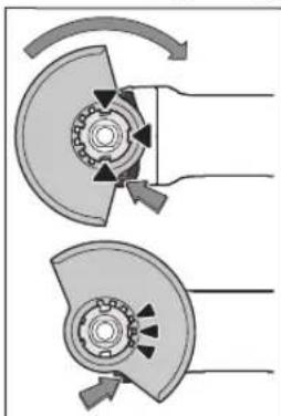
Poknadi tbaXHCHN KOKxy
(11)Ha KpInneHHa
eneKtpoiHCTpyMeHTi TaK,
Uo6 KoOnBaHI KynauKh
3axnCHoro KOKxya
BIDIOBIAIKNKpINNEHHIO.
Pnp UcbMy HATNCHTb i
TPmaTe HATNCHEHM
po36NOkyBaJIbHH BaxInb
(1).
HaTHCKAIOH Ha 3axHCNH KOxyx (11). HAIINbTe NOro HA WNIky WNIHNDEIA TAK, 606 60ptNK 3axNCHO KOxyacBHa QnaHeu
eneKtpoiHCTpyMeHTa, i noBepTaTe 3axnCHN KOxYX Do THX nip, pOKn BIn He 3aIe BiDyTHO y 3aueJIeHH.
BCTAHOBITb 3axnCHNI KoxyX (11) B Heo6xIDne DnI BIKOHyBaHOIpoBOTNIOLOKeHH. IINZBOrnpHTCHITb PO36NOkyBaHbHH BaxInb (1)DOROp i NOBepHITb 3axnCHNI KoxyX (11) y notpihe nOIOKeHH.
YctahOBIOJIe 3axHCHN KOxyX (11) 3abxHn TaK, 06 BcI 3 cepBOHI KynauKN po36NOyBaIbHORO BaxKeI (1) 3axoNDn y BiINoBDH IOBOp 3axHCHO Koxyxa (11).
3axchnn KoxyX (11) notpi6no BCTaHOBN TAK, 0o6 icpn He Morn Netit H hnpMky onepatopa.
3axnchnn KoxyX (11) NOBHHNOBePTaHc Hnne npnnpBedeHHI BIOHOPO36NOyBaNbHOBOBKeA (1)!Inakue BxOJHOmy pa3i He MoXHa npoDBKByaTHpo60Ty 3eneKptoIHCTpyMeHOMI IHO Heo6XiHO 3dATy cEPBCHY MaHCTepHIO.
Bka3iBa: 3aBnKoOBoHMM KyNaqKaM Ha 3axNCHOMY KOxyci (11) MoXHa MOHTyBaTH nIe 3axChnKOxBy, IOp03paxOBaHH Ha BInNoBdHn enEKeTpoHcTpyMeH.
3axnHmKoQyXdNpO3pi3aHH
Длpo3pi3aHЯ 3a donomoro 3b'ra3aHoro a6pa3nBy Heo6xIDHO BHKOPHCTOByBaTH 3axHCNH KOKyxДл po3pi3aHH (16).
Дяpo3pi3aHHKaMeHIO Heo6xIHO 3a6e3neHTN DOCTAHTBIDCMOKTyBAHH Nnly.
3axnCHKOxyDnpo3pi3aHHA16MOHTyETbCA TAK CAMO,RA3axnCHKOBNaK DnIaNfYBaHHA11.
BNTJXHHKOBNAK DnPa PO3pI3AHH3 3IOHOHTHM cynopTOM
BNTJXHHKOBnakDnPO3pI3aHH3NIOHETHM CyNOPTOM (30)MOHTyETbCtAK CaMO,AK 3axHCHNKOBnak DnA WlifyBaHHA(11).
DdaTkoBa pyKoTka
Praoute 3 eneKtpoHcTpyMeHToM nHe 3 dOdaTKOBIO pyKoTko10
PnKpyTtBdoaTKOBy pyKoRTky (10) B3anexKHOCTi BID cnocobypo80n npabOpuy a6o nibOpuy BiD rONOBKn peyKTopa.
Demnpepha doaTkoBa pykortka

EmnpephaDQaTkoBa pykOraK3MeHwye Bipapuioi,taKIMuHOM, 3abe3neue6bnpncMHy
Ta 6e3neu npauo.
He 3dInchOnTe XoDHnx 3mH Ha DoaATKOBi pyKoHTci. He BnKOpHCTOByTe NowKOxEny DoaTkoBy pKoHTky.
3axnctdnypykn
Дяpo6OTn 3 rymoBOO onOpHO uINiPyBaIbHOIO TAPINKOIO (21) a60 3uawKOBOU uITKOIO/duCKOBOO uITKOIO/BIAHNONIOJI6HMM KpyROM 3aBxDN MOHTyIte 3axHCT Dn pyK (20).
3aKpInHIOte 3axnCTIpyk (20) 3aDOnOMOrIO
doAtKOBoI pyKoRTKN (10).
MOnTaX WnIpyBaBbHnx po6OuHx iNcTpymeHTiB
Ipeep ycima maHinynuaHH 3 eKtpoihctpymeHTOM (Hap.,TexHINHM O6cnyroByaHHM,3amHOIO pObooro IHCTpymeHTaTOO),aTAKOX npH Noro TpaHCNOPTyBaHHi 36epirAHHI BmMaHTe aKymyTAOPHy 6atapeo 3 eKtpoihctpymeHTy. Pn HHeBAIMCHOMY BKIOUeHHI BmMHKaaya icHy cHe6zneka nopaHEHH.
He TopkaTec8 uNidyBaunbHnA6o BIDpi3Hnx KpyRb, NOKn BOHN He oxOHOHTb. Kpyr nCnIbHo HarpIbaIbScnIyacpoBtN.
OuNCTiB uINiFyBaIbHnIuINHdEnb (19) I Bci npn3HaueHi DnMOHTaKy Detani.
PnMOHTAKiI DEMOHTAKi WnifyBaBbHnx po6ouHX IHCTpyMeTIB HaTCHITb Ha pikcatop WnHHdene (3), 0o6 3aificcyBatn WnifyBaBbHm WnHHdene.
Pepu,HX HATNCKaTH Ha fikcatop uHHnHdiena 3aueKaTe, NOKUINiPyBaIbHNuNNHdEnb He 3yHHntbcra! B IHOMy paai eNEKTPOIHCTpyMeHT MOKe NOIKOINTNCRA.
UnlifybaIbHn/BiDpi3HH Kpyr
3BaKaIte Ha po3mipn 1iDyBaIbHnx po6OuHX IHCTpyMeHTIB.OTBIP 3aDiAmETpOM MaE nacyBaTHdo onOpHOro fnaHr. He BnKOpHcTOByTe aAnTepn abOp nepexidnKn.
PnBHKOPNCaHHi AnMa3Hnx BIDpi3Hx KpyrIB CnIKyTe 3a TMM, uo6 CTpiKa HAnpMky OepeTaHH Ha AnMa3Homy BiDpi3HOMy Kpy3i BiNobiAna HAnpMky OepeTHe enekTpoiHCTpymeta (DNB. CTpiKy HAnpMky OepeTaHH Ha rONOBu peNyKtopa).
PocniobBHCTbMOHTaKy 3o6paKeHa Ha CTOpIHcI 3 MaIOHKAMN.
ДяЗakpinenHHIИФуВальHOrO/BiDpi3HOrO Kpyra BnKOpNCTOBYITE WBNkO3aTnCKHy raKy (14) 6e3 6yNb- RKNX INCHPymETIB.
BHKOPNCTOByTe WbIKo3aTcckHy RaKy (14)IINe dIy IiIpyBaIbHnx/BiDpi3Hnx KpyRIB 3 MAKCmAbHIM diametpOM 150 MM.
276|YkpaHcbKa
WBnKo3aTnckhyraky(14)03BONrEbCBAHKnOPcTOByBaTHnnneDnnaWnifyBaIbHNx a60Bip3HHX KpyriB.
BnKOpHcTOByTe Nmue 6e3DorAHy, HenoWkoJxEny WbUdko3aTHCKHy raiKy (14).
Pn3akpyuBaHni cnidkyIte 3a THM,06 MapkipoBaHa cToPOHa WbNko3aTHCKHOI rAIKN (14) He DnBnAacn Ha nifyBaHbHm Kpyr.
ДязakpinenHHHUniHyBaBnHOro/BiDiPI3HOrO Kpyra BHKOPNCTOByIte BHKIOUHO DoaHy WBnK03aTHCKHy raKy (14).

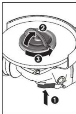
06iDnCKa He E DoCTaTHIM.

KIIIOU NID DBA OTBOPH.
INCTpymEnTa, 06B Bin He BIKpyTNBCB iD uHHnHnIa nIac Bn6iry enkTpoHCTpymEnTa.
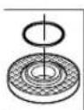
B onopnomy fnaui (12) naeHTpyooyMo noryx anoxonbca nactmacBa deTalb (kInbcke Kpyrno nepepi3y).Kko kInbckpyrno nepepi3y hema a60 BOHO
nowokxene, onopnHn pnaheub(12) Heo6xidHO 0ob8'3KOBO 3aMHINnepeNDaJIbM BHKOPNCTaHHM.
Piicra MoTAtkx uNifyBaIbHOro iHcTpymeHa, nepu HIX BMHKaTH npnlaad, nepeBipTe, nn npabHbHO BMOHTOBaHH uNifyBaIbHn iHcTpymeH t Hn BInbHO Bin MOKe o6epTaHc. BneBHITbc, 10 uNifyBaIbHn iHcTpymeH He 3aivnae 3axncnn Koxyx a6o inwi Detani.
Bianonodhnnwnidybanbnnkpyr
Pnpo60TH3B1INIOI6HMMKpyrom3aBXHMOHTyTe 3axHCTnnpyk(20).
Tymobn Taipuaactm wnlidybalbnh kpyr
Дяpo6it 3 rymOBHm tapinactHM uiofyaBbHMM Kpyrom (21) 3aBXM MOHTyTe 3axHcT dЯpyK (20).
IocniobHbCTbMOHTaKy3o6paKeHaHa cToPiHci 3 MaIOHKAMN.
Hadihthe rymoby onophy wniybanbHy tapinky (21) ha wniybanbHH nnHnndelb (19).
PnTnCHITbwniDyBaIbHy Wkypky (22) MiuHO Do HmKhboro 60ky rmyoBoI onOpHoi wniDyBaIbHoi TaipINK (21).
Hakpytib kpyrny raiky (23) i 3aTnHtib ii 3a donomoropo pIKKOBOKIOIIOA nID DBA OTBOPN.
BiDcMoKryBaHHnHny/Tnpch/ctpyxkN
TnKx MATEpianib, Hap., NaKOpap6OBnx NOKPntb, 0MICrTaB CBNHeu, DeKHX BnIB DepeBHH, MIhepaniB i Metany, Moke 6yTH Hebe3neuHm DnI 3DopOB'a. TopKaHH a6o BnXaHH Nnny MoKe BnKlnkaTu y Bac a6o y oci6, 03haxOaTBcno6n3y, anepriHi peakui ta/a60 3aXbOpOBAHn DnXaNbHx WnXtiv.
PbHn nny, kHnnp. dy6OBn a6o 6yKOBn nnBBAJIObca KaHcpeoreHHMN,OC6bNBO CnOnyeHHI 3doabkamn nIb O6p6Kn DepeBHN (xPOMAT, 3ac6b nI3axHCTy DepeBHN).MATEPIAIN, 10MICrTb a36ecT, D3BOJNAcTBcO6p6nTH NHe cneuaJIaICTam.
Cniikkyte3a do6poIO BENTINJUeHO ha pObooumy Micu.
- PekomeHnybCBABraTn pecnipatophy macky 3
φiNbTPOM KNaCy P2.
Doepejkyteca npnnncicB odo o6pObHax matepiianib, 0o diotb y Bawin kpaHni.
YHKaTe HAKOINHcHnHa pO6Omy Mci. MoKe JntKO 3aMaTnCra.
Po6ota
Touatokpo60tn
BcTpOMJIHHaKymIaTOpHOI GaTapei
BcTpOMITb3apJxKeHnakymyIaTOP(8) cnepeDy B Hixkky eneKToPiHCTpyMeHTa, 106 akymyIaTOPdo6pe 3aqiKcyBaBCa.
BMnKaHHBmHKaHH
IooyBIMKHyTN eneKtpoiHCTpyMeHT, nocyhTe BmHKaU (6) Bnpepe.
36 36 36 36 36 36 36 36 36 36 36 36 36 36 36 36 36 36 36 36 36 36 36 36 36 36 36 36 36 36 36 36 36 36 06 06 06 06 06 06 06 06 06 06 06 06 06 06 06 06 06 06 06 06 06 06 06 06 06 06 06 06 06 06 06
Uo6BHMKHYtneneKtpoHCTpyMeHT,BiDnyctITbBMMKaU (6)a60,AkyoBH3aqiKOBAHn,KOPOTKoHaTCHITb BMMKaU(6)HaaziI BHH3I ToDI BiNpyCTIb Noro.
PipeBnKOpHCTAHNMe nepeBipIeTneIiDyBaIbHI IHCTPMEHTN. UIiyDyBaIbHI po6oHi IHCTPMEHTN MAOTb 6yTH 6e3OraHNO MONTBOHI i BILHO NOBepTaHcA. 3dINCHtB np6He yBIMKHeHH NpHaMHI ha 1XBUNHy 6e3 HabaHTaKeHH. He BHKOpHCTOByTe NoWKoDKeH, HEPBI Hi IiDyBaIbHI IHCTPMEHTN abo Taki, 10 Bi6pyOt. POnkOJKeHi po6oHi IHCTPMEHTN MOxTyIaMaTcA i CnpuHNrT tineci yUkoDkeHH.
BIMKHeHH np ciNaHHI

y pa3i HecnodibaHoro cinaHH
eneKTpoHCTpyMeHTa, Hanp. y pa3i
6IOKyBaHHy y po3pi3i, noDaua CTpyMy Ha
dBHyrN nepeHbAeTbCra eneKTPOHIKO.Ipn
cboMy CbitIOJIO nICBciuyBaHHo pObooi
30HH46NMaE 6iHMMaIHnKaTOp CTaHy (35)- YepBOHM.
3063HOBYyBIMKHYeNEKTPOHCTPymENT,BMMKHITB BMMKau(6)i3HOBYyBIMKHTBeNEKTPOHCTPymENT.
3axnctBid NOBTOPHORNOycky
3axnCTBID NOBtropHOro ncyk3anobirae HEKoHTpObOBAHOmy 3anycky eNekTPOiHcTpymEnrYnicna nepe6oIB 3eNekTPOIocTaaHHM.
Ypa3iakTbaujIzaxHCTyBID NOBTOPHORO NcKy IHnKaTOp CTaHy (35)6nMaC cepBOHM.
Uo63HOBy yBIMKHytn eneKTpOInCTpyMeHT, BIMKHiTb BIMNKa4 (6) i3HOBy yBIMKHiTb eneKTpOInCTpyMeHT.
BmKHeHHypaizydpay
B6yDobaHa CnCTeMa BmKHeHHa y pa3i yapy BmNkAe eneKTpoIHCTpymENT, kTilbKn BiD BapAeTbC0 nIiNtory nicna naHn. Pn cybomy iHnkatop cTahy (35) 6nmae cepBOHM. Uo6 3HOBy yBIMKHyTH eneKTpoIHCTpymENT, BmMKHTb BmHKau (6)i3HOBy yBIMKHITb eneKTpoIHCTpymENT.
278|YkpaHcbKa
InTepeicKOpHcTbAua(INB.Man.D)
MoynbIHTeppecyKOpncTyBaay(5)CnyryeDnBCTaHOBNEHKnBKOcTIopeptIB,aTAKOXnIHnKaqCTaHy eNkTpOiHcTpymehta.
BctahOBnEHKinbkOcTi o6eptB (GWS 18V-10 SC)
KhONKHO BCTAHOBENH KINbKOCTI oEeTIB (34) MOxHa HanaUTOByBTH Heo6xIDHy KINbKiCTb oEeTIB HabITb nIac po60n. Dahi, 10 MICTaBcB H NkChenOdaH TabNci, -nne peKomeHdaii.
| Materiak 3actocybaHH Po6oHni | iHcTpyMeHT | PibEnb BCTaHOBHeNoI KINbKocTi o6eptiB | GWS 18V-10 SC (100/115/125 MM) [xBNL. \( {}^{-1} \) ] | GWS 18V-10 SC (150 MM) [xBNL. \( {}^{-1} \) ] |
| Metan KpaizobAHn, BvdaJIeHNHa IpxH | UaIIKOBn Dnck 1 4500 4000 | |||
| HerjazaiOua StaIb | UIIiΦyBaHn BOLOKHnctH Kpyr 2 6000 5500 | |||
| Metan O6dIPHe StIiΦyBaHnH | UIIiΦyBaHn H Kpyr 3 9000 7500 | |||
| Metan Po3pi3aHH UIIiΦyBaHn H Kpyr 3 9000 7500 | ||||
| KamInHn Po3pi3aHH AIIMa3Hn BViDiPI3H N Kpyr 3 NaIpRIMHmCaIa3KaMn (BvdiP3aHn KaMeHIO npINpYCKaCTbCЯ IINIe 3 NaIpRIMHmH CaIa3KaMn) | 3 9000 7500 | |||
Habehehi 3naueHHa ctyneHB KInbKocti oeprib e opiehtOBHMn.
Donyctma KnbKictb 6eptrib npnaadra nobHHa K Minimym BiNIOBidaTH MaKCHMaJIbHi KInkbocTi
0eptib, 3a3aueha eeneKtpoiHcTpymEnI. Ppna, 06o 8epTaTbcB WbNdue Do3BoneHoro, Moke 3namatnc i po3netitnc.
IIndkaTopnCTaHy
PnB Bipri3aHNI npaKoHTe 3 NOpimHIM npocyBaHHM
po6oYoro IHCTpyMeNTa y BiNIOBIAHOCTI DO o6pO6IOBAHO
mATEpiany. He HATNCKaTe Ha BiDp3HN Kpyr, He
nepekooyte HOrO i HE XHTaHTe HOrO.
PnnaHHe raBmyte Bip3HH Kpyr npTHCKAHHM 360ky.
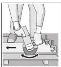
EneKtpoiHCTpyMeHToTpi6Ho 3aBxKnBnKOpNCTOByBaTH npOTnHaPmky o6epTaHH.1hakwe icHy eHe6e3neKaHEkOHtponBoBaHOrO
BnHbHaHn i npop3y.
Pn po3piaaHH npo4inib i KBaIpaTHN Tpy6 KpaIe
NoHHaHT N haMHebJoro nepepiy.
P03pi3aHHKaMeHIO (IMB.MAN.C)
Pnpo3pi3aHHKAMEHIO Heo6xIDHO 3a6e3neHTN DOCTAHBICMOKTYBaHH Nny.
Bdraite nno3axnchmyacky.
EnkpoHcPmENTdo3BnEbCBAKOpHcTOByBaTHnnne dny cyxoro po3pi3aHH/cyxoro uNifyBaHH.
Kayinci3ik HycKaynapbI
Kannbl 3neKtp Kypanbl Kayinci3ik Hycaynapbl
ECKEPTY
BapnbikKayinci3dk HcyckaynbikTapbH XeHe eceptnenepeipokbHbI3.
TexnKanbIK Kayinci3ik HcckaynbIKTapbIH KHe eceptneepdi cakTamay TKbIH COfByHa, ept XHe/ hemece aybp JapakaKaTTahynapFa aBIn Kenyi MymkH.
BonaawKxmbictap yin kayinci3ik hycKaynbiktapbi MeH eceptneneppi cakTan KObih3.
KayinciknHyckaynbkaptbHa naaanaanbHnFaH 3neKtp Kypan aaybHIn KeiJeH Kyat anaTbH 3neKtp KypanapbHa (Xeninik KaBen Mehen) XHe AKKyMaTOpHcN Kyat anaTbH 3neKtp KypanapbHa (Xeninik KaBen XoK) KaTbcBap.
XymbicophbihhKayinci3di
KymbocpHbH Ta3a XHe XapbIyCtHaB3. JactHaFAn KHe KaapanfblKaJnnapa CAtci OKHFnap 6onybl MyMkiH.
3NeKtp KypbInFbcBn XapbInaTbH aTMocepapa naHaanah6aHb3,MbICanbI, XaHaTbH cybIKTBk,ra3 Hemece 7aH 6ap 6onFaHa.3NeKtp KypaI YWkbHApDbl XacainbI, an Onap Hemece 6ynapDbXaHdbpy MyMKIH.
Bananap Meh 6aBnayuBnapDy 3neKtp KypanbHAn anbc yctahb. Anyaynap 6aBnay Kofanyha anbln Kenyi MymkiH.
282|Ka3aK
3nekt kayinci3iri
3NeKtp aHbIpnapb po3eTKara ca6oynbTnic. AHybpbl ekwahewkaHdA Topi3e 03reptneH3. Kepre KocbnfAH 3NeKTP KypanapbMeH aanTep aHbipnapbH naDanaH6aHbI3. 03reptInmErH aHbIpaN MeH cHKeC po3eTKanap 3NeKTP TybIKaTnybIH KayinIH TEmHeTei.
Ky6bipnap,padnatopnp,nnTanap men cybitkiuTAP cnKTbI Xepre Kocbinfah 6eTpe TmHei3. DeHeH3 Xepre Kocbinfah 6oNca kofapb1 TOK cFy Kayini naJa 6oanaB.
3neKtp Kypanapnbl Kaanbipda Hemece binnanblkopwayda naaanaan6aht.3neKtp KypanbHa KipreHcy TokcoFyKayinIH Kofapbnatabl.
Kabebdi Tnicti 6oMaHaH pete naDanaHbA h3. Kaebdi 3neKtp KypaBnH tacy, KeTepy Hemece ToKtaH 1bIFapy yuH naDanaHbA h3. Kaebdi bICTbIK, MaH, ETKip KbIPnap XHe XbINXbIManbl 60IweKtpeH anbc YCTamaHb3. 3aKbIMdAnFaH HEmec 6bITbcIn KetKeH Kabenb Tok COY kayinH KOFApbilaTaBbl.
3NeKtp KypanbH cbPTa naDanaHaFaHda cbPTkB JaaNap yin cai Ka6ebdi naDanaHbHbI3. CbPTa naDanaHyfKaapaMdbi Ka6ebdi naDanaHy TOK cory KayinIH TEmeHdeNi.
Erep3neKtp KypanbH bINFaNdbI Kepde naDanahy Kepek 60nca,Onda KopraTbH eWipy KpybInfbcbl (RCD) apKnbl KopFAnrH ToK Xenicin naDanaHbHb3.RCD naDanaHy Tok cOry Kayinih TMeHeTeJI.
KekeKayinciik
3NeKtp KypaIbI naIaIaNyda a6aB 6oNbIbI3, KymbIcIbI3IbI 6aKbIaNbI3 KHe npacATbl naIaIaNbHbIbI.3NeKtp KypaIbI waPsaFAn Ke3de Hemece eciptki, ankorObn Hemece dapi ocep etKeH Ke3ne naIaIaNb6aHbI3.3NeKtp KypaIbIH naIaIaNay Ke3iHne aHcbI3IbIK aybip Keke JxapakattHyfa anbln Kenyi MymkIH.
Xeke KopraTbH Xa6DbIcTapdbI naDanaHbIb3.
OpaBIM K3 KopFaHbICbIH TaftbIb3. HaMacacbl,
cbipraHaBtBnKayinci3ik aK KNIMdepi, WneM HeMece
ecTy KopraHbIITapbl CNAKTbI KopFaBIIW Xa6DbIKTapbl
THicti KaFdaNapda KOJaHbIN Xeke XapaKaTaHynapbl
KeMeNTei.
Ke3eKcikce KocbinybH anbH any.ToK Ke3iHe XaHE/Hemec6 bataepnap XHHa HcOcydAnbH, Kypanbl KOTepy Hemece TacydAnbH eipriwewik Kynde BonybHa Ke3XeTki3H3. 3NeKtp Kypanbl CayCAkTB eipriuke KoBIn Tacy Hemece KCKbH Kocybl 3NEKTP Kypanbl THOKKa KOC cyCATci3 OKfara aBbN Kenyi MymKH.
3NeKtp KypaBn Kocyaan anbH KeiReH pettey cbHaCbH Hemece KINTI anbN KOHyb3. 3NeKtp KypaBnHbH aHaNaTbH 6enirIne KaFah KINT Hemece cbHa JKeJ XapakatthyFa anbIN Kenyi MyMkiH.
KoN KUH ICTTneH3. Opaabim Tmict TaHbHn nen Te H canMaKbIbIKbIcKaTaHbI3. BykYtINmereH KaDaHnpda 3eKeTp KypanBih 6aKbInaHyh CaKaTaNbl.
Tnti KIM KINH3. Boc KIM Men awekeinepdi KIMHej3. WauBHb36e H KIMdepdi XblXbImaBbl 6eWekTepeH anbc yctahb3. Boc KIMdep, awekeinep Hemece y3bH wau XblXbImaBbl 6eWekTepe apKbIbI TaPTbIybl MYMKIH.
ErepwahbifapbnKHHayXa6bIKTapbHaKocy Kpybfbnapb6epnireh6oNca,OndaonapKocynb6ObyHxaneTnti peTe KONdanybHaKe3 Xetki3iIs.uaHxHHayDbnaJanaHya HFa 6aJIaNaHbCTb3HrHapDbKEMeTI.
HA3AP AYDApBIHbI3!3heprnmeH Xa6bIKTaydbIH TOblkTaHe JxkeKeen ToKtaTbNybi Hemece 3heprnmeH Xa6bIKTaydbI bAckapy Ti36erHH aKaynaHybl CanapbHaH 3neKtp KypanBbIH jXMybcHda Kiipic NaJa 6onFaH Xa4dA, 6yattanMaHaHbIfBaHka Ke3 XeKtiin (6onFa HkaDn) 6apbn, axbpaTkHiBbBbKn. (Owipy) KaNbHa KeTIpiH3. Keninik awahbl po3eKaadn 1bIFapbH3 Hemece anbl - canMaBl aKKymnTopDb IaxbpaTbHbI3. Ocbpeket apkbnlb 6akbinaHbTbH kaTa icke KocblnydbH anblh anacbl3.
3neKtp KypanapbH nainanany XeHe KyTy
KypanbI aca kon kxyktemei3. KymbcibHb3 yuih XapamdbI 3neKTP KypanbIH naDanaHbIH3. XkapamdbI 3neKTP KypanbIMeH KepeKT Kymbc aMafBHa dpybic api ceHIMdi Kymbc icTeic3.
Axbipatkbblbdybce mec 3neKtp Kpaanbnaaana6ba13. Kocyra Hemece eupyre 6oImaHTbH 3neKtp KpaBbl kayinti 6bn, OHj XeHdye KaKeT 60ana.
Xa6bikTapbi peTey,6oIweKTePiAnMaCTbpy Hemece Kypanbl anbln KOIOaH andbIH aHbIPbpo3eKaadH bIfapBb13 XeHe/Hemece aKKyMyaTopbl anbln TaTaHb13. Byn caKbApeketi 3neKtp Kypanblb6aiKaycblaKocblybHa xon 6epMeiDi.
PnIaHbIMaTbH 3eKTP KypaIapdb6anaIap KOnblXeTneTIH XaHa KOnbIHbI3.OcbIaNpbl6IImeTT HemeC OcEePTneepdi OKbIMarAH aamapra6yn KypanblpaiaaIaHaNyKaON 6epMei3.Taxipi6eci3 aamap KOnbIHda 3eKTP KypaIapblKayinti 6oIaBl.
3neKtp KypanapbH ykbntbkyiH3. Ko3FaImanb6nweKtepeHKeeprici3 icteyine Xhe KeTtenin KaMaybHa, 6nweKtepeH akaycbHemece 3aBIMdAmMaFah 6onybHa, 3neKtp KypanbHbH 3aBIMdAmMaFahbHa Ke3XeTki3H3. 3aBIMdANFaH 6nweKtepi 6ap KypanbH naDanaHydAn dBIn XeHDeH3. 3neKtp KypanapbHbH dypbic KytimMeyi JzatahmbOKfApa ce6n 60bnj kataabbl.
Keckiacnantapdbetkipxhe Ta3a Kynde caKaTbI3. DypbckytinreHxhe Keckiw xneKtepi etkip Keckiw acnantap a3 KeTtenin, Kecinetih 6eTke Ohaia 6afblTanaDb.
3NeKtp KypaBbH, Xa6DbIbTapbl, anMaIbI-canMaIbI acnantapblx xeH.6.ObHyckaynapra ca naiDanaHbHbI3. CohbiMeH xymbcIwapTTapbImeOpbHaTbH apKeETepre Haazap aydApbHbI3. 3NeKtp KypaIbpH aPhaMfAH xymbcIcTapda naIdanaHy kayinti.
BaTape KypanbH naiDAnany kHe KyTy
TeK eHdpywi cHnattarh 3apdtafbimMe KaTAta3pndtahb3. Batape JHHaftbHb6ip typihe caJ 3apdtafbw 6acka batape JHHaftbIme KOndaHyda ept Kayinie aabn Kenyi MymkIn.
3NeKtp KypaIapbH TeK apHaBbI TaRaBbHdFaHaf 6aTaper XnHaKTapbMeH NaIaHaBbHbI3.Ke3 KeIeRc 6aca 6aTaper XnHaKTapbH NaIaHaHy KaPaKaTaHy MeH ePt KayinHe anbIn KeIeI.
Erep6atapenXHHaBkOJdAnya60MaCa,ohbI typeiyu,TbHn,Kint,Were,6paHaHeme6BaKa KIiMeT3attapDnYCTaHbI,onap 6ip TepMHAnDaH6ackacbHa6aHaNbICXacaybIMyMkn. BatapeTePMHaIapbHKocyKynHMeceoptkeanB KenyiymMkn.
Dpybc emec naaandahyda 6ataperean cybiktbki arby MyMKH, oAH TMKei3. Erep TIN KANcaHb3, cymen wainbin tactahbi3. Erep cybIKTBk Ke3re Tnce dpirepre xabapacbHb3. Batapean hwaKaH cybIKTBK KO3y Hemece KyIKTepe an bil Kenyi MMyKH.
Kb3MeT KepeTy
3NeKtp KypaBbHa MmamDbI XeHdeywi TeK 6ipDei Kocankb6oWIEKTEpMeH KbImET KepeTyI Kepek. Byn 3NeKtp KypaBbHbIKayinciairIH CaTaNbIKAMTaMaCb3 etedi.
BpybIbIbIK tericTey MaunHnapbIH naJaIaHny Ke3iHderi Kayinci3ik TexHHKacbl
MaHdAnay, axapay, cblm KblnBkneh Ta3anay Hemece a6pa3nBTi Kecy aicTepi yin kayinciDik hcykaynapbl
Byn3neKtp Kypanbl MauDanafbiw, axapnaftbiu, cbIMdbIK KbIbWbIK Hemece Keckiiu acnapan petiHde naDanahyra aphanfaH. Ocb3neKtp KypanblBHH XHaHbHdArfbcEckptynpdi, HcKaynapdb, cypTepdiXe HnattamapdbOkbH3.BapnbK TexHNkabIK KayincidiHcYcaybIKTapbIH opbHdaMay TOKtBuH COFybiHa, ept XaHe/Hemece aybp Jkapakattahynapra aBIn KeJyIMKIN.
XbntbipatcyncktbI epekeTepre ocbI neKtp Kypanbl aphanmaHan. 3neKtp KypaBHa ahpamMaH epeKeTep 3HH, Kayin KeTIpIn XeKe XapaKaTTaHyra anbN Kenyi MYMKIH.
Acnan eHdpuyimeH xacanmaHan Hemece ycbiH6araH Kepek-kapaKapakTapbI naHanaH6aHbI.Kepek-KapaK 3NEKTP KypanbHbI3Fa caN KeNc De, Kayinci3 Kymbic icTey KaMTaMaCbIeITIMei
Xymbic Kypalbi aHnblmDapbHbH yFapbHbI caHbI 3neKtp-KypalbiHa-KepcetInre H MaKChMaNbl baiHaNblMdap cHbHa-TeH-BonybKepeK.EcenTeReH
KbIaMdbfBHaH Teiipek icTen TypFaH KepeK-JapaKaTap CblHybl, yWbIn Ketyi MyMKIH.
PaindanaHaTbIH XMybIC KypaBbHbIH cbiptKbI-DnAmETpi MeH-KanBbHdbIfb3NeKtp-KypaBbHbIH-EnWeMepHe caH-bonybiKepe. Dpybc TaHdAmarHan Kepe-KapaTap Dpybc-KopraamaybiXHe-6akbnaydAnbHybIMyMKH
KepeK-kaapakTapdbH 6ypaHaanbI KockbIwbl MaDanaFbI WnnHdeniH 6ypaHaacbHa caB6onybI KepeK. FNaheunen opHaTbINFaH KepeK-kaapakTap yin OnapdbH opta Teciri fnaeun H opaty dAmetpihe cai 6onybI KepeK.3NeKTp KpaanbIHOp Hpaty acnTapbHa cai 6onMaFAH KepeK-kaapakTap TeHrepimHeH bIfbn, KaTb Tep6enin, 6akblaydbj XofaHTyfa ekeeni
3aKbIMdANFaH KepeK-JkapakTapBn I naDanaHa6BaHbI3. 0p naiDanaHyad anBbHn abpa3NBt IeHreKe CNkTb1 KepeK-JkapakTapBc bChbIK neH JapbIKTapra, etek Hnckini JkapbIKTapra, T03y HeMece apTbIKbblIKTapBHa, CbIM KblMaKTb6oc HeMece cbIHah CbIMapFA TeKcepij3. Erep 3neKtp KypanbI Hemece KepeK-JkapakTap Tycin KetC, OHIN 3aKbIMdAMaFAnh TeKcepij3, KaKET 6oNca 3aKbIMdAMaFAn KepeK-JkapakTapBn OPHaTbHbI3. KepeK-JkapakTapBd TeKcepIn opHaTuYan coH, e3iH3zi XHe 6acka aamdpBn aiHaBn TpyfAn KepeKJkapakTap aiMfaHn AnbIcTaBn, 3eKTP KypanbH MaKCNMaNDbjXyKTEcyi KbIMDaMbKnEh 6ip MmHT aiHaNDbipBnI3. 3aKbIMdANFaH KepeK-JkapakTap eDeTte CbIHAK yAkBtBHa Da hHaBn.
Xeke-KopraHbc KypanapbH (Kayinci3ik Keinipirih, KopraHbc KaKahb6ac Kmim Xehe T.6.) naDanaHbHb3. PnndanaHyfa 6aNanbHcTb1 KopraBm MackaHb, Kayinci3ik KeinipikTePH KOaHbHb3.Kepek BonFaHa, WAnMackacBn, Kynak KopraBtApbH, KonFANxHe KiWi a6pa3NBti 6enweKtePi HeMece daBnHaMa 6enweKtePIn yctai anatbIWe6epxAna AnXanBbHbN naidanaHbHb3. Typni-JyMbICrapt 6apbcBHa naJa 6onatBn YsatbH-BeTeh 6enweKtePeH-KopfAthn Kayinci3ik Keinipirih naDanaHbHb3. WAnMackacBHe Mece peCnnpatOp ycaK 6enweKtePeH, WAnHAn Kopraybi Kepe. Y3aWynap cty-KabineH XoFAntyFa eKenyi MymkiH.
Betenahamapdbihxmbic-ahMafbHAn-Kayinci aMakta6onybIHKAMTamacb3etih3.Xymbic aMafbHa KipetIH Ke3 KeIeH adam Xke KoprfaB1Xk6dbkTAPbI KhoI Kepe.KaibHdama 6enweKeptepi HEmecc bHFaH Kepe-XapaKaTap ybln,apeket aMafbHaH TBIC KaJa KaKapat Tnri3yIMykH.
Kecetih Kepek-KapaKaTah XacbipH cbIMapFa THoi MyMKIN apeKeTTepdi JXacaraH Ke3e 3neKtP KypbnfBHK TK OKwaynHaF YCTay KaBihAH YCTaHbI3. Erep kcyui acnan icten TypHcbMFA Tnce 3neKTP KypalbHBMetan 6enweKtepi icterin NaDanaHybHbTOK COybl MyMKH.
284 Ka3aK
AinabIn TypFaH acnAn Tobnk TokTaHaHwa 3neKtp KypanbIn KOHaHbI3. AinabIn TpyFaH KepeK-KapaKapTap 6etKe TnH, 3eKtp Kypanbl 6aBnaydAn 7bHyb MyMKH.
3NeKtp KypaBnKacbHb3da KeTeepin TpyFaHaKaCnAbl. AHaHbIn TyprAh acnAnTapra Ke3deNcoK TIO KIMiHj3di yCTan, acnAnTb DeHeH3re XaKbH anapbyMymKiH.
3NeKtp-KypaBbHbH-KenDety-caHbInaynapbH KNI Ta3apTbHbI3. Ko3raTTKbIw KeNDEtKiIi waHbI Kopnyc iHiIe TapTbI, YHTaKTaNFaH MeTaNDbH KeN KHNanybl 3NeKtpneHyre aBbIN KeI MyMKH.
3NeKtp KypaBih XHaTbH MaTePnAldapFa KaBih naHanaH6aHb3.YuKBbHdAp-ocbl-MatePnAldapDbI TyTaHdbIpbyMymKiH.
CybIKbiI cybIKtki KaKetETeTIN KypaBnH-naDanaHb3.CyHeMece-bacaJa CybIKbiI CybIKtki TaNaDanaHy 3NEKtp-TofBiHH-COFybla-anbl-Kenyi-MMKiH.
KaTapbIM MeH Tnicti eceptneep
KaIapbIM 6yn CoBIFAH HEmeCe yctanfah aHaHbIn TpyFaH
JeHRENEK,ETEK DnCK,KBIIwA KHeMeCe BACA KepeK-JaPakKa
6oNaTbIH peAKUIN. CORY HeMeCe YCTay aHaHbIn TpyFaH
acnantbIKyNan KetyiHe XaHe 3NeKTp KypalbHbIH
6aKbIaNayCbIaHanybHa,Kapcbl 6aFbTTa aHaNbyHa anbIn
Keenei.
Mbcanb,erepabasntdi DnHreNek daBHnDama apkblcofbina,cofyekeine KipeTIN dHreNekTHIeTI Maepnaf6etihKeipin,deHreNekTHKETepinyiHe Hemece aBbInhKeTIaBnKetyiMymkin. DeHreNek naDanaHybilaHemece oanapiyuBmykIH,bydneHreNekapeketHH6aftbHa 6aBnA hBaunahCTb. Abpa3nBTi deHreNekTePocbkaFdaDa cbHbIn KeTyI de MyMKH.
KaTapbM 3nEeKTP KpyaBnH KaTe naDanaHydAn XaHe/ HEmec Ke Tae NaDanaHy aicTepeHH HeMece WapTapbIHc anDaPbHaH 6oNaTbH JkaPaKaTAPDbH aIaNbIaNabI.
3NeKtp-KypaBbH-MbIKtan yCTaHbI3,
DeneHcI-6eH-KoNbHbI3 Kepi cokkbHa
KapcbIbIK-KepcTe-anatbH-KyIe-yCTaHbI3.
OpaHbIM KocMbMa TyKaDaH yCTaHbI3, 6ap 60nca,
OcbIaI cke Koc Kez IHe KaTapbIM Hemece aHany
Ke3Inde MaKcMaIaNbI 6Akblay 60nabl.
PiadanaHybI aiHany peakunnapbI meH kaTapbc
KUHTepiH andbH ana Kepyi MymkH.
KoNbHb3dIeKawah aHaHbnTpyfAnacnAnaKaBnTaNaHbI3.AcnaI KOnbHb3Fa KaTapbIM XacayblMYMKIH.
Denehi3ni 3neKtp Kpaan KaTapmbMa XbInkTHbH aHaMaKaTApHaNactbIpMaHbI. KaTapmb KpaanBbI KbCbIy Ke3IHnDe DeHreNeK aHaNyBaHa Kapcbi SaBfTTa anapaBbl.
BypbIHTapbl,etKip wETepdi eHderene acacak 60nbHb3.AcnantbcoKnabH3HEmece KbcnabH3. BypbIHTap,etKip wETep Hemece cbpyaHaHbnTpyaH acnantapblkbcIn,bKaBnaaydbinKofaTbyHa Hemece KaTApblMa anblkEnyi MyMKIH.
Apanay wbiXbiph, aafw kecatih xy3di Hemece ticti apa kynih opatnab13. Myndan-xymbic
Kypanapbl Kepi cokkbfa Hemece 3neKtp KypalbH 6aBnaybl Kofantyfa-anbin-Kenji.
MaianaHMy Mea6pa3nBti Kecyre apHanrah Kayinci3dk HcKaynapbI
TeK3neKtp KypaBbHb3 yiw HycbHbINFaH DeHreNEK TYPnepin XeHe TaHaNFaH DeHreNEK Yiw H KypbInFaH KOpFaBbITb NaHaNaHbHb3. Ocb3neKtp KypaBbHa apHaMaFaH DeHreNEKTeP Dpybc KOpFaMai, Kayinti 60anaBl.
OpTada KbcBnFaH DeHreNEKeTHMmDanaaTbH6et KopFaBtBnA cTbHdopHaTbinyIkePek. Dypbc opHaTbIMaFaH KopFaBtII,JeHReNdeH IbFbIN TypFaH DeHrEKeK KaCbI KopFaJybl Kepek Emec.
KopraftbIw 3neKtp Kypabiba KaTbI opHtbnBIMakcmandbKayinci3ik yuH opHaIacybI kaxet,ocbnaJ deHreNekTIH MHHMaIaNbI KOneMi naDanahybifa Kapan TypaDbI. KopraftbIw naDanaHybHbCbIHFa dHeReneK 6nWeKeTpIneH, DeHReNekke Ke3deCOK THIOeH XeHKeIMepdiKaHDbipybMyMKIN YUKBHApdaH KopraNbIbI.
- DeHreNEkTePdi TEK YcBihBInFaH naDAnany TypnePiE cai KOndAnhybKepe.KmCan: Kecywi DeHreNEk WeTimen MaDAnamHa3. Kecywi-deHreNEkTe P MaTePhaNDbI WeTimen Kecyre apHaHaH,DeHreNEkTePre-acep etetIH 6yipnIK KyuTep bIKNaJIbHaH Olan CpHybMyMKIN.
TaHdAnFaH DeHreE K yHn ApaHbIM Dpybc enWeMderi XHe NiwHderi 3akbIMdaMaHaF fhaeTepi NiDanaHbHbI3. Dpybc-TaHdAnFaH epHemeKTe tericTey DeHreneriH Tiperi BOnaBx He OHbHcBHy KayinH aDbH-anaDb. Kecywi DeHreKeTepi HfaHeTepi MaJdAnay DeHreneri fhaeTepi Hen Baca Bony MykIn.
YIkeHpeK 3eNkTp KpaanapbHbH To3FaH deHreKeTepin ndaanha6hbi. YIkeH 3eNkTp KpaanapbHa apHaHaFn DeHReKeTep KiipeK acnantbH JXofapbipak KblnamdbfHa apHaMaFAH 60bn, XapbIybl MymkiH.
A6pa3nBtkeCyre apHanraH KocbIMwa Kayinci3dk Hcyaynapbl
Kecywi DeHreNekei KbcIpaHb3 Hemece OHk KaTbI 6acnab3.KecikTepeHdetyeopekeKxacamab3. DeHreKekeKaTbIbacyXyKTeMeHI-XaHe-DeHreKekeKc Ke icTe-bpyFa-Hemece-baHaNbICTbpyFcaXiIMtan-BonyBH XaHe-Kepi coKbHbIH Hemece-DHReKeK-CbHybIHbHbIKTImaIbIfbH-apTbipad bl.
- Deheni3di aHannbipbnfra dnHrenekTin 6ip cb13bIKKa Hemece apTbHa opHanaCTbIPMaHbI3. DeHreNEK Deheni3deH apbl KblnKbica, bIKTMaN KaTapBIM aHaNbTIpyFaH DeHreNEK NeEneKTp KypalbIH Deheni3re Tikeen KblnxblTybl MyMKH.
DnreK KbcBcHc Hemece Ke3 KeIeH c6benten KecytdokTatca,3Nektp KypanbH eipin, DnreK TOnbIFbIMeH ToKtaFaHwa 3Nektp KypanbHa TImeH3. DnreK icTe npFAnDa Kcy dReneriH anbin
KoIora apekeT KacamaHb3, OHTnece KaHTapbIM naHa 60anaJI. DeHreNEK KbICbIyblHbIH Ce6eBH XKO YUHc6eBIs i3en DpybIcTaHbI3.
Kypan daibin dama TaYpFaHda 3NeKtp KpaBn KaTt Kaocnab3.Kecydi 6actMaC 6ypbIn, andbimEn-DeHreKeTI-Tonbik-aHaHbIM CaHbHa XeTKi3n anbHb3. OHTNECE, KeCKIW DnCK TYbblIN, daibHdAmadH KeTePInI KeTyI Hemece-Kepi COKkbifa eKeYi MyMkiH.
TipeKaHbIepi Hemece Ke3 KeIeRrTBIM YNKeH daBHdAma DeHReNE KbcBHyblMeH KaITapbIMHbIH anDbHanyuWIn. YNKeH daBHdAmanap 33 aybpIbFbHaHminyi MyMKH.DaBHdAma-KeCy CblbIFbHa-JaKaBH-XHe-DeHReNEKTIH-eki XaFbHaH-Ta tipenyi KepeK.
Bap Ka6bipranapa Kii Ki cekikri Hemece 6acka Kepin6eHIN aMaKtapda opbHnayda abaHaHb3. 1bIpyan DeHreNeR ra3 Hemece cy Ky6bIpaBH, 3JIeKTP cbIMdApDbl Hemece HbCaHnapDbkcyi MyMKIH, aJ 6yI KaHTapMFA anBn Kenyi MyMKIH.
Akapnay apeketepi yuin kayincik HcykaynapbI
TbIM yIKEN axkapnay dNCK KAFa3bH naIaNanH6aHb13. Axkapnay KAFa3bH TaHay Ke3InDe eHdipyui YcbHBCTapbIH opBHaHb13. Axkapnay KypabIa npAHFaH TBIM yIKEN axkapnay KaF3bI KbIPtBly Kayini nainda 60bn, 6yN KcBcIyFA, dNCKTIH KapbIyBaHa HEmec eKaITapbIMFa anbl Keny I MyMknH.
CbIM KbluBkneH Ta3anay opeketepi yin Kayinci3dk HycKaynapbl
KbIbIKbIH KapanaHbIM opeKeT ety Ke3iHde de KblbIKTapdbH WauBipAHTbHdbfH bckepiH3. KbIbIKbTI KaTbI 6acBn,cbIMFA Kyu TycipMeH3. CbIM KblbIKtapby Kya KImre XaHe/Hemec Tepire Kipin Ketyi MymKH.
ErepcbIMKbINbIKnENTa3anayyinHkopraftbU WcBInbIFANbONCA,KopraftbU cbIM DeHRENEK Hemece KblwakKa THMeyi Tnic.CbIM DeHRENEK Hemece KbIbIKbIH DnaMetpi JxMByC KxKTEmecHe Hemece UeHTpHpyraJIbIK KyuTep ce6beHEn YNKeIOI MymKIN.
KocbImwa kayinci3ik hcykaynbikTapbl

Kopfahbi K0e3indpikti knihi3.
Kaxketti 3eey Kypanapabih naDanaHbIn Xacbipinfah CbIMdapbl TabbiH3 HeMece Kayantbl XeprinikTI yibm ekindepin wakbipnb3.3neKtp CbIMdapbHa TIO eT HEMeC TOK cFOyBaHa anBn Kenyi MymKIN. Ra3 Ky6bpHb3aKbIMday JapbNlcKa anBn Kenyi MymKIN.Cy Kc6bpHb3aKbIMday MaTePnAnDbK 3nHfa anBn Kenyi MyMKIN.
TericteyKeheKecyDnckinepiHcyiHaHuaTMHei3. 1e6epnepxymbcke3iHneKb3aabl.
KyaT 0uCe,MbIcAbl,AKKyMyIaTOp Wewince, coHdiPrii6BeKITKiinAnbHb3XeEwipyni Kyre opHaTbHb3.By apKbIbI Ke3deNcoKocBly 6onMaJbI.
Даындаимьбекгiz.Кысу Кypалын HeMece KыСкИКа opHaТынfaн Даында Молынб eн calыбтbpfana,6epik yctanaы.
AkkymyIaupnab3. KbicKa tyibkTany Kayini 6ap.

Mbicanb, aKMyIaTOpbl KbiyDah, coHdaI-ak, y3dkiC3 KHy KApblfHaH, OTAH, cydAn XeHe bINFaIaH KOpFaHbI3. Kapblny kayni 6ap.
AkkymnTOpDaan3aKbIMdaHafHemeceIypbic naananaHaFAnKaFaJa6byuBfrybMyMKin.Byn KaJaaiaIiKeTa3aayaaKipri3iHaXeHaFbMap 6oNa,MeunHaiBkKEMeAJIbHb3.Bynap TBHbcany XOJdApBHITIPkeHdpYi MyMKIn.
Byn akymnyTopnapdbI TEK 3iH3dH Bosch eHIMi3ne naDanaHbHbI. CoI apkblnB1 aKKyMnTOpDbI KayintI, aptBk KxKTEyDeH caKaTcBla3.
Were Hemece 6pybui CnKtby yTb3aTAP Hemece cbiptkbe cep apkbbln bKKyMnyrA TOp 3aKbIMaHybl Mymkin. By Kicka TyBkTanyra anbin Kenin, aKKyMnyrTop XaHybl, TyTH WbIFapbyi, JkapbNybl Hemece Kb3bn KeTyI MymKH.
A6a60bnH3! 3NeKTP KypanbH Bluteoth6eH naIanahyda 6acka Kypanap men Xa6bikTap, ywaK Xhe Meuunnaibk Kypanap (Mbicanbi, KapnoctmynTOp, ecy Kypanapbi) Xymbicihda Keeprinep naJa 6onyb MyMKIN. CoHaJ-ak XaKaBH TyphaH aamdap meN xayahnpfa 3nH Tybipy Kayin TOBik XOIO MymKIN EMEc. 3NeKTP KypanbH Bluteoth" 6eH Meuunhaibk Kypanap, XaHApMaB 6eKETepi, XMHnblk Xa6bIKTap, kapiny Kay6i 6ap XHe KaBnabH aiMaKTap XaHbIH da NaIanaanbAh3. Bleetooth 6ap 3neKTP KypanbH yawkaptda naIanaanb6aHb13. DeHere XaKbH aMakTa y3ak yakbit naIanaanb6aHb13.
Bluetooth ce6 genrici cypet genricimn (norotntep) 6ipre Bluetooth S1G, Inc KOMmaHcBbHt tipKeIren tayapnb6 genricxhe Myniri bOnbIn tabbnadbl. Ocbie3/cypet6enricin Robert Bosch Power Tools GmbH apkbbl naDanany nuehenHerizHne opbHdanaBbl.
Θhim XəHe KyaT CnnaTTamacbl

Bapnik KayinciDik HycKaynbTapbiH Xhe eceptnepei okbHb3. TexnKanblk KayinciDik HcckaynbTapbiH Xhe eceptnepei caTamay TOkTBH COfYbHa, opt XHe/Hemecae aybp JapaKaTTahynapfa anblin
Kenyi MyMKIN.
NananyHyckaybIbIHbH anFb6enirHHcpeTepin
ekepij3.
TaarbiHdany6oBbHwa kondahy
3nektpkypanbcyblnaindaanh6aMetaanHaJxHeTactaH kacalfahMaTePnaIapdBkeCyre,cbdbipbnanyFaXHeUeTKaMeHEnDeyRe apHanFaH.
286|Ka3aKa
BaIIaHbIcTbI a6pa3INBTEp KcEmiMeH Kecy VHH KecyTe apHaFaH apHaHb I KopFaFbH KaITamaHb I naJaHaHy KepeK.
TactbkeckeHJe HhH KekkiKti copbuiybi KaMTamacetiHi3.
ApHaHbTericTey KpaIapbIMeH TipKecimc 3JekTp KpaIbI ereyKym KaFa3bIMeH TericTey YuHn naJaHaHyFa 601aIbI.
3JIeKTP KyaIbIbIH,JepeKTePI MeH napAmETpIepiin
Bluetooth Low Energy Module GCY 30-4 opHaTbnFaHda
Bluetooth paIOTeXHOIOINrCbI IeKTP KyaIbI MeH
MOBbIbIcHbI KpybIbIapKbIbI TaBImaJdayFa 60JIa
BHeHeHReKypaMdbI6JIeKTeP
KepcertireH Kypamactap HmipheHre hcyteTepi 6ap
Bettere 3eKtp KypalbHH CnattamaBHa ca.
(1) KOpFaFbIa KaIITamaFa apHaJIFaH 6yFaTTaydAn IbI Fapy nIHtiperi
(2) Kopnyceri aiHaIy KΘpcetKici
(3) ⅢHnHdJIeJIbdi6eKITyTJYmeci
(4) KApbIKnHOHTbIKKMbICmMb(GWS18V-10SC)
(5) IaiJaIaHyuHHTepfeiCi
(6) KocKbIu/Θwipriu
(7) Bluetooth MoayinH KaTAMacB
(8) AkkyMylTOp
(9) AkkmyIITopIbIbOcATy nephe
(10)KocbIMHaTgKa(6eTIOKMAYaHbipbTaF)
(11) TericTreye aphaFaH KopFaBII KAnrTaMa
(12) έHreJek KImacbIbap tripeK φlaHaHei
(13) tericrey ueH6epi
(14) KbIJaTapTKbIi COMbH iIMKeIIeH
(15) KaTbI McTaJIbI Ta6KaTbI duKi
(16) Kecyre apHaJFaH apHaJIb KopFaFbIa KaITaMa
(17) Kecy dinckic
(18) Tyrkα (6eri oKIIayIaHbIbpyIFaH)
(19) Akaipay mnnndeni
(20) KoJ KOpFaFbIbIbI
(21) PeSeHke tericTreY TpeJIkeA
(22) Akaapay dncki
(23) έHreIekri comh
(24) TocTaFaH Tepi3i KblnBbA
(25) AImactbIK 6ypFbIay TaKi
(26) 3apnKyI Kepcerkiu yinH nephe (GBA 18B...)
(27) 3apnKyiii KepcetkiiaaKKMyIITopbl (GBA18B...)
(28) 3apnKyni Kepcerkiu yinH nephe (GBA 18B 6,3 ProCORE18VB..
(29) 3apnKnyKepeCtkiAkkymyIITopb (GBA18B6,3ProCORE18VB...
(30) BaFbTTaybIITap 6ap Kecyre apHaIFaH KopFaBII KaTamaA
(31) AImac Kecy Nckci
(32) AKKMyIITop 3apIaTay KYH H KepCETKII (naiJAAHnyBbHHTepphiCi)
(33) AHaJIbIMap caHbI aJIbH aJa TaHday KOpceTkii (naJaHaHyIbI HHTepfeieiCi
(34) AHaIbIMap caHbH aIbH aIa TaHyepheci (naJaHaHyBb HHTeppeci)
(35) Επεκτρ ΚγραλβνH Kγι Κθερετκιδι (ηαιδαλαγιδι HHTερφείci)
(36) ApTbIK KxKTeMeDeH KopFay KePcetKici (naaJalaHyIbI HHTeppeci)
A)BeHHeHReH HeMeCe CnHaTaNFaH Ka6bIKTap CTaHApTbI KTeK3y KeJEMIMeKAMTBImaIb. ToJIbK Ka6bIKTapd 6i3iH Ka6bIKTap 6f4apMaMb3aH Ta6ac3b.
TexHHKaJIbIK MJIIMeTTep
| Бурштейк terитем Maшинась GWS 18V-10 C GWS 18V-10 C GWS 18V-10 C | |||
| ΘимΗміп | 3 601 JG3 0.. 3 601 JG3 2.. 3 601 JG3 1.. | ||
| ЖуMbіс Керneyi B= 18 18 18 | |||
| Номнанды aiналыm саны мин | -1 | 9000 9000 9000 | |
| Бoc aiналу сәті мин | -1 | --- | |
| Мамс. ожаралу дискісі дhamетри MM 100 115 125 | |||
| Тerитем ушинданініні көрійміл M 10 M 14 M 14 | |||
| шинданінікій көріймілінінінінінінінінінінінінінінінінінінінінінінінінінінінінінінінінінінінінінінінінінінінінінінінінінініn | eH, KОД YЗБДББМ 22 22 22 | ||
| Кері coKKы Kežin'deri Θшіpy жуйosci | ● | ● | |
| Кайта Козfaлу сaКтɑfьшы | ● | ● | |
| Журіс тeжeredni | ● | ● | |
| Айналыздap саны Тaнда | --- | ||
| Салmaы EPTA-Procedure 01:2014 Кужаты са | |||
| - Вибрацьларды коюfa aphalfaн Косьміla TуТКась бap | KT | 2,6-2,8^) | 2,6-2,8^) |
Ka3ak|287
| Бурыштейteríctey Maшинасы GWS 18V-10 C GWS 18V-10 C GWS 18V-10 C | |||
| -.stандарты Косьимба Туksасы бар кг 2,4-2,6 | A) | 2,4-2,6A) | 2,4-2,6A) |
| ружсат ETINREн Коршay Temператypасы | |||
| - zarаддауда °C 0...+45 0...+45 0...+45 | |||
| -жуmbic icterеенье B) kyатышикtenген °C -20...+50 -20...+50 -20...+50 | |||
| Усынblлган akкумларторгEBА 18V... | GBA 18V... | GBA 18V... | |
| GBA 18V...W | GBA 18V...W | GBA 18V...W | |
| ProCORE18V... | ProCORE18V... | ProCORE18V... | |
| Усынblлган зараятукалары AL 18.. | AL 18.. | AL 18.. | |
| GAL 3680... | GAL 3680... | GAL 3680... | |
| Инданцийлak Akкумларторгар ушin | |||
| Усынblлган зараятукалары | GAL 18W... | GAL 18W... | GAL 18W... |
| Деректéri tасьmanдay | |||
| Bluetootha | Bluetooth* 4.2(Tемен куат)c) | Bluetooth* 4.2(Tемен куат)c) | |
| Сигэн intервалы c 8 8 8 | |||
| Мakсималдik сигэн жетetiн Кашьктыfbl D) | M 30 30 30 | ||
A) naiiHnHaH akKymJrTopra 6aIahbctbl
B) <0°CtemnepatypanapbHdkaKaYaTbi WeKTeTren
C) MoBnIbIbI TePMnHaIap Bluteoth TEmeH KyaT KypbnFbnapMeH (4.2 HycKaCb) yInecimDi bonyi Xane Generic Access Profile (GAP) KOndaybl THIC.
D) JeTeTIH KaIbIKbIK cbIPTKbI WapTAPFa 6aIIAHbICTbI petTE, coBHIMEN 6pIre naIaNanHfA KabINay KpybnIFCbHa 6aIIAHbICTbI, KaTTbI e3repYi MymKiH. Ka6bIK 6BmEnep iWInHe XaHE MeTAN Kepeprine (MbICAN, Kabipranap, cOpener, yEmoanT.5.) apKbNbluBleoth
| Бурытейк TerICTeу Машинасы GWS 18V-10 | SC | GWS 18V-10 SC | GWS 18V-10 SC | GWS 18V-10 SC | |
| ОниnomиWIPI | 3601 JG3 3.. | 3601 JG3 6.. | 3601 JG3 4.. | 3601 JG3 5.. | |
| ЖуmbIC KePneyi | B= | 18 | 18 | 18 | 18 |
| HOMINAHДы aiHалбIM саны | MHN1 | 9000 | 9000 | 9000 | 7500 |
| Бос aiHалу сati | MHN1 | 4500-9000 | 4500-9000 | 4500-9000 | 4000-7500 |
| мамс. ожаралay дискici dihaMetripl | MM | 100 | 115 | 125 | 150 |
| ТerICTeушпнделінчрк озмасы | M 10 | M 14 | M 14 | M 14 | |
| шпндelloн орек озмасын eн кeн YЗындьБу | MM | 22 | 22 | 22 | 22 |
| Кері coхсы кеінderі ошіру жійech | ● | ● | ● | ● | |
| Кайта козгалу садагышы | ● | ● | ● | ● | |
| Журіс төжөriшü | ● | ● | ● | ● | |
| AiHальIMdap санын тандay | ● | ● | ● | ● | |
| Салмafы EPTA-Procedure 01:2014 kUЖATын саɪ | |||||
| -BИбрацяларды яюга apHAлган KOSымда түкасы бap | Kr | 2,6-2,8A1 | 2,6-2,8A) | 2,6-2,8A) | 2,6-2,8A) |
| -стандарты Косымда түкасы bap | Kr | 2,4-2,6A) | 2,4-2,6A) | 2,4-2,6A) | 2,5-2,7A) |
| рүкатэрүнгүрүрүүүүүүүүүүүүүүүүүүүүүүүүүүүүүүүүүүүүүүүүүүүүүүүүүүүүүүүүүүүүүүүүүүүүүүүүүүүүүүүүүүүүүүүүүүүүүүүүүүүүuces | ℃ | 0...+45 | 0...+45 | 0...+45 | 0...+45 |
| -Jжмьс icterе徳E) куаты šeKFteлген | ℃ | -20...+50 | -20...+50 | -20...+50 | -20...+50 |
| Yсынылган akку мунлгоррп | GBA 18V... | GBA 18V... | GBA 18V... | GBA 18V... | GBA 18V... |
288|Ka3aK
| Бурblattык Tericteу машинабы GWS 18V-10 | GWS 18V-10 | GWS 18V-10 | GWS 18V-10 | |||
| SC | SC | SC | SC | SC | ||
| GBA 18V... W | GBA 18V... W | GBA 18V... W | GBA 18V... W | GBA 18V... W | ||
| ProCORE18V... | ProCORE18V... | ProCORE18V... | ProCORE18V... | ProCORE18V... | ||
| Усынblattын заюдай куралдай AL 18.. | AL 18.. | AL 18.. | AL 18.. | |||
| GAL 3680... | GAL 3680... | GAL 3680... | GAL 3680... | |||
| Инданык akкуmarлар ушin | GAL 18W... | GAL 18W... | GAL 18W... | GAL 18W... | ||
| Усынblattан заюдай куралдай | ||||||
IepeKTePdiTacbImaNay
| Bluetooth® | Bluetooth® 4.2 (Temeh Kyat) C1 | Bluetooth® 4.2 (Temeh Kyat) C1 | Bluetooth® 4.2 (Temeh Kyat) C1 | Bluetooth® 4.2 (Temeh Kyat) C1 | |
| Сигнал Иntервалы c 8888 | |||||
| Мakсималдьк сигнал жетetин Кашыты[Fbl]01 | M 30 30 30 30 |
A) naaHaHfA aKKyMnTOpFa 6aNaHbIcTb
B)<0℃temnepatypanapbHdaKaaytei
C) MobnbTepMNHaap Bluteoth TEmeKyAT KypBfBnApMeH (4.2 Hcyckacb) yInecimDi bonyi He Generic Access Profile (GAP) KondaybTHIC.
D) KETeTIH KaIbIKBk CbIPKb IaPITapF aIaNbHcTb peTte, coHbIMeH 6ipre naIaNaHaF aKabINay KpybnfbcHbIa HaaNnHbCTb, KaTtB e3repYi MyMKIH. Ka6bk6enmep iHIne Jxhe MeTAN KeeprInep (MbICanbl, Ka6bprAnap, cpeep, yemOaH T.6.) apKbNI BLeetoth XeTeTIH KaIbIKBtfbl KaTTbl KcCKApby MymKiH.
Uybn kane dipinney typanbaknapa
| GWS 18V-10 C GWS 18V-10 C GWS 18V-10 C | |||
| 3601 JG3 0.. 3601 JG3 2.. 3601 JG3 1.. | |||
| Дыбicшыгару мэн Dipei EN 60745-2-3 boй bHиа ecenteIren. | |||
| A-Men Белгіенгін пінБматикалык куралын дыбic kуші anecdTE Temeн degire TEH boládi | |||
| Дыбic KaTыlby DiENrEi | ДБ(A) | 79 | 79 |
| Дыбic'tbK kyat DeHrei | ДБ(A) | 90 | 90 |
| Флшey dəncɪdīri K | ДБ | 3 | 3 |
| Кунakтbi kopray kypaɪdapbɪn киɪɪdɪs! | |||
Kannbipin MHepeia a(h y6afttbH BEKTOBIK KocbiHBicbl) XaHE KdanciDiri EN 60745-2-3 (6oc xypic) caH aHbiktanFAH:
| Бернreich 寿命论 (Дереки endey): | ||||
| a_h | m/s² | 6,0 | 6,0 | 6,0 |
| K | m/s² | 1,5 | 1,5 | 1,5 |
| Егелям karлайдзяпарлay: | ||||
| a_h | m/s² | 3,5 | 3,5 | 3,5 |
| K | m/s² | 1,5 | 1,5 | 1,5 |
| GWS 18V-10 | GWS 18V-10 | GWS 18V-10 | GWS 18V-10 | |
| SC | SC | SC | SC | |
| 3601 JG3 3... 3601 JG3 6... 3601 JG3 4... 3601 JG3 5... | ||||
Db6bcIbIbIgApyMnHepi EN 60745-2-3 BoBbIbHa eceTeTReH.
A-Meh 6enrilehren nHeBMaTHKanbIK KypaIbH dIb6bc Kyyi aTeTte TEmeHderire Teh bona
BbblcKaTbIbIbIb DeHreI B(A)
79797981
Ka3ak|289
| GWS 18V-10 SC | GWS 18V-10 SC | GWS 18V-10 SC | GWS 18V-10 SC | ||
| Дыбысты Куатdenгей | дБ(A) | 90 | 90 | 90 | 92 |
| Олшey дэлсizdiri K | дБ | 3 | 3 | 3 | 3 |
| Курасты корray Куралдарын Клипз! |
Kannblipin MHepeia (yw 6afttbH BektopbIK KocbHbCbl) Xe He K dnciir EN 60745-2-3 (6oc xypic) caH aHbKTanFAH:
AkkymnyTopdbi3apdTaay
U Tek Kepek-KapaKapTap 6etInHe KepCetInReh 3apRtay KypanDapbH naiDanaHbHbI3. Tek KaHa ocbI 3apRtay KypanDapb ci3iH 3neKTP KypaBbHb3dbH iWInDe NHTINHOHBik AKKyMylrTopMeH cAkec.
Hcyakay: akymyntop iihapa 3apraTanfah Kynde Ketytkiinei. AkymyntopdbIH TOnbIK KyatbIH naDanaHy yiwohbl anfa pet naDanahydah anDbIH TOnbIK 3apraTaHbI3.
HINHNOHBKAKKYMNIATOpbI NaaDAnHy Mep3imH KBCAPTyCbI Ke3 KeRHe YAkBiTTa 3apdTayf6oNaDb. 3apdTay npocecin y3y aKKyMNIATOpdbI 3akBIMAnybHa eKeMeNdi.
HITNIHOHBKAKKYMYNATOP3NEKTPOHdbIK3NEMEHTTePdI KOpFay(ECP)apkbltepeh3apJKOFAHTyHaH KOpFaHaH. AKKMyNATOP3aepJbIKoK60nca3NEKTPKypalbIKopFaHbIC CXEmacblApkbblEipinei:lanmbi-canmaIb acnan 6aca KaO3fAmMdbI.
3NeKtp Kypanbl ABTomatbl OwkeHHEN COH KCKbI/ 6ipriwiE hdi 6acyb60mAb13. Ntnece aKKyMyIATOP 3aKbIMdaHybl MMKH.
KokbictapdbkaetaeHneyTypaibHyckaynapdbOpbHaDb3.
Akkymytnopdbwey
AkkymyIaTOpdbH (8) eki 6ekity 6ackbIbIb 6ap, onap aKKMyIaTOpdbI ay npheciHIN (9) ke3eNcoK bacblbn, aKKMyIaTOpdbH Tycin KeTyIeH cakTaIdb. AkkymyIaTOp 3neKtp KypalbHa opHaTynb 60nca, OhI cepiInne KaBbHda yCTan typaDbI.
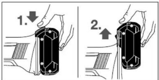
AkkymyIaTOpdb(8) bIfapy yuiH auy nepheci (9) 6acbln, aKKMyIaTOpdb 3neKTP KypalbHaH anFa TaTbIn 1bIfapbHbI3. OcbI Ke3de Kyu canMaHbI3.
290|Ka3aK
AkkymyIaTOp 3aparTay Kyi KepcetKiWi (aKKymyIaTOp Typi GBA 18V...) (ACypertin KaPahbI3)
AkkymyIaTOp 3apIaTany Kyi HnHnKaTOpBbHbN (27) yJXacbl Japbl KApbl IHObl AKKMyIaTOp (8) 3apIaTany KyiH Kepcetei. KayinciikMakCaTBHa 3apIaTany KyiH 3JeKTp KpaJIbH ToKtTaBn 6bpIn OpbIHday MymKiH. 3apIaTany KyiH KepeTy yuiH (26) TyMeWeCIn 6acblb3. ByHbI aBlHfAH AKKMyIaTOp (8) MeHeH da opblhday MymKiH.
Kapbiknodbi Kyatsti
Y3dikc3kapbK 3Xxacbln2/3
Y3diKci3Xapbik 2xXacbln≥1/3
Y3diKci3japbik1xkacbn<1/3
KbIbIbIKTaHbIH KApbIK 1x PeaepeB Xacbl
(26) nephecin backaHHah coeew6ip kapbIKnHOJI KaHbaca OHbl anlmactbypKaKTe.
Hcyak: AkkymnyTop 3apd Kyi NaananaHysbu INItepeciIne (5) KepceTinei (kapaHb3,NaananaHysbu INItepeci (D cypetih KapaHb3), Bet 293).
AkkymyIaTOp 3aparTay Knyi KepeTkiu (aKKymyIaTOp Typi GBA 18V 6.3Ah, ProCORE 18V...) (B cyperin kapaHbIa)
AkkymyIATOpbIH 3aprTany KyI INHdkATOpbIbIH (29)6ec
Kacbl Japbl INObl AKKMyIATOpbIH 3aprTany KyIIN
KepcTei. Kayinc3ik MAKcTaBHa 3aprTany KyIH 3neKTp
KpaJIbIH ToKtTaBn 6bpIn opbIHay MyMKIN.
3aprTany KyIH KepCteTy yuH (28) TYMeueCih 6acbHbI3.
Mybl anbIHFaH AKKMyIATOp MeHe De opbIHay MyMKIH.
KapbiknnoobKyatbi
Y3dikci3 xkapbik 5 x xacbln >80 - 100%
Y3dikci3 xkapbik 4x kacbln>60-≤80%
Y3dik3xapbik 3xacbln >40 - ≤ 60%
Y3dikci3kapbik2xXacbn>20-≤40%
Y3dikci3xkapb1xxacbn>0-≤20%
KbInbInbIKTaHbINXapbIK1x 0% Xacbln
(28) nephecin backaHHan coeewip kapbIKnHOJI bKaHbaca OHbl anlmactbykKaKet.
Hcyak: AkkymnyTop 3apJ Kyi PaananaHysbu INItepeinHe (5) Kepcetinei (kapaHb3,PaananaHysbu INItepeci (DCypetINKapaHb3),Bet 293).
KopfaraithacnantbI ophary
Akkymnatopbl3neKtp Kypammen Ke3 KeTren Kymbictapbl (Mbicanbl, opHaty, Kb13Met Kepcety, T.6.) 6actay andbHda, cohdai-ak, 3neKtp Kypanbl Taebimdanay kHe caKTay Ke3iHne bHapbHb3. Kockbl/ewipriuke Ke3eNcoKTHIO XkapaKaTTAHy Kayin H TydpaBbl.
Hcykay:KymblcKe3iHneTericTey WHe6pei 6y3bnca Hemece KopFaBll KaTtMa/3nEeKtp Kypal KypbInFbnapbl 6y3bnca, 3nEeKtp KypaIbIb 6ipEn cepBnc Kb3MeTHe Xibepy Kepek, MeKeHkaIapbl « TapaByHaH KapaHb3.
Tericteyre apHanFaH KopFaBlii KaTtMa
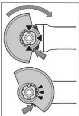
KopfbaI KAnTaMaHb1 (11)
3neKtp KpyaBbHbH
natpoHBHa KopfbaI
KanTAMacbHbH, KOtay
XyDblpKlJauApbl NaTPOHra
CaNkec KeIReHwe
CanbHb3. ByFATTaydA
UbFapy NHTiperH (1)
6acbln YCTaHb3.
UHHndEnb MoHbHdaFbl
KopfAflb KaTAMaHb1 (11)
6acbln, KaTAMaDaFbl
6byPTKnTi 3neKtp KpyaBbH
PhaHei He OByPb3bHb3
KHe KOpfbaI KAnTaMaHb3
IbipteKHeBb6bcEcTeTReHWe 6ypbHb3.
Kopfabi KaTtAmabHb (11) KyiH Kymbc 6apbcih TaanTapbHa cai opHaTbHb3. ByyuiH 6yFATaybH bIbFapy nHTiperH (1) Xofapb6acBbH3 XaHe Kopfabi KaTtAmabH (11)KaXeT KyIe 6ypbHb3.
Kopfabi KaTamaHb1(11) 3 Kbi3bn JxDipbikwa 6apnbbl 6yfaTaydaan uBnFapy nHtiperinde (1) Kopfabi KaTamaHb1(11)Thictoi oyBkTapbHa kipetih erin opHatbHb3.
KopraftbH KanTamaHb (11)onepaTopdbH XaftbHa KapaaykBnDapdbH ywby6oMaHTbHdaOpHaTbHb3.
KopfbaH KanTama(11) 6yFaTaydAn hBbFapy nHtiperiH (1)naiDanaHaHa dra faha 6ypbinykepek! ΘNtnece 3NeKtp KpyaDnaiDanaHy MymKin Emec XHe cepBnCTIK KbI3MeTKe Tancbipy Kepek.
HcyKay: Koprafbll KaTtMaJdaFbI KoTay KyDbipbIKuJapbl (11) TEK 3neKtp KpyaIFa KapaTbH Xa6dbkTbOpHaTydbi KaTAMacb3 eTei.
Kecyre aphanrah KopFaBliW kaTama
BaihaictbI abpa3HBtep Kemerimeh Kecy yuH apKaaah Kecyre apHaTaN KaTamaHbI naDanaHbIb13 (16).
Tactbkeckenhee wahhbH KETKINIKTI copbinybH KaMTaMaCbI3 etiH3.
KopFaBbI KAnTama (16) cohImeH bipe tericTreYe
apHaJFaH KOpFaBbI KAnTama (11) petIHn De opHaTbIaNbl.
BaftaybIupap Kecyre apHanraH Koprafbi KaTtMa
BaftaybIITapbI (30) 6ap KOpFaBII KAnTaMa tericteyre apHaFAN KOpFaBII KaTtAmA (11) peHJe de opHaBInaBl.
Kocbimwa TyTka
3NeKtp KypaPbHbI3DbI TEK KocBIMwA TYTKa MeHeH naDanaHbHbI3 (10).
KocbMuaTyTKaHbI (10)peykTopnb6actbH OHKaFBHda Hemece coJXaFbHda bypan 6ekitiH3.
Dipindeydi 6acehenetin Kocbimwtytka
Vibration
Dipindeyni 6eehdetetih KocbMwTaTKa dipindeyi KEM KOJnbl JyMbIC icteye Mymkhik bepeji.
KocbIMwTaTyTkAhbl 03reptnHj3.
3aKbIMdAnFaH KocBIMwa TyTKaHbI naIdaan6aHbI3.
Konkoprafbiwbi
Pe3eKeni axapnay TepenKecimEn (21) Hemece ToctaraH Tpi3di KbluBk/Dnckini KbluBk/Jennyiw Tpi3di terictey weh6epimen Xymbictap ywih apkaan KON KoprafbibH (20) KNIH3.
KoN KOpFaBbIbIH (20) KocbIMa TytKa (10) KEmerimeh 6ekitih3.
Akapnaybii Kypanapbih opHaTy
AkkymarTopbl3neKtp KypammeH Ke3 Keiren Xymbictapblb (Mbicanbl, opnaty, KbImet Kepcety, T.6.) 6actay andbHda, cohdan-ak, 3neKtp Kypanbl Taebimanday kHe caKtay Ke3Inde WbIfapbHbI3. Kockbiw/ewipriwe Ke3eNcoTTHO JkapaATaHy Kayr Tybpadbl.
Terictey KHe Kecy Dnckinepi CbYfAHaTMMeia.
Terictey uHHdeniH (19) xHe 6apbIk OPhaTbIaNbIH KypanapdbTa3anaHbI3.
A6pa3nBt Kypanblb 6ypan any Xane 6eKity yuHIN HnHnEbnDi 6eKity Tymecin (3) 6acbln, nnHnEbndi 6ekiriH3.
WnHHdEnbdi6ekity tyHmecin TeK WnHHdenb TOKTaTbINFaH KyIe 6acBbI3. 3ntne 3neKtp KypaNbIH 3aKbIMaybHbI3 MymKIn.
Terictey weh6epi/kecyweh6epi
Terictey KypanapbHHH eWHeMepin cckepiJ3. Ophaty Tecirihn dAmetpi tipeK pfaneueke caKece 6onyk Kepek. AanTepnepdi Hemece kAnfactbipfbw TetikTepdi naananaanbH3.
Anmac Kecy ueh6epnepin naDanaHFaHa anmac Kecy ueh6epiNderi kblNkby TfaBtBhlbKepcTeKici 3neKtp KpaIaFbI aHany 6faBtBHa cAneKec 60lybH KaIaFanaHb3 (peykToplbK bactfB KepcTeKhi KapaHb3).
Ophaty peti cypette6ap6epekepcitiren.
Akapay/kecy nckiciin 6kity yuih kblam TaTkbl CombiHb1 (14) bacaacnbsi naaiahaHb3.
KbIaam TapTkbl Combl (14)TeK MaKcMaIbIK dAmetpi 150 MM-reeiH 6oIaH axapnay/kecy nckinepi yuiH naDanaHbHb3.
Te3TAPKbI COMbIHbI (14)TeK axkapay HeMece Kecy dNckicimEn naidanahyfa 60nabI.
By3bIMarAH mHcI3 XbINdAM TApTKbIw COMbIHdbi naHaanahbHbI3 (14).
Eypan KOJDA XbIaam TapKbIu COMbIHbHbI Jx3bIraH XaFbI (14) axapnay dNckicine Kepcetneyi Ke3 xetki3iH3; 6faftTama HHeKeCTIK 6enrire Kepcety Tnic cypetih KapaHbI.
Akapay/kecy ducckicih 6ekit yuih TeK kaHa XHHaKTbbl KblnDaM Kbicy COMblHn naDanaHbHb3 (14).
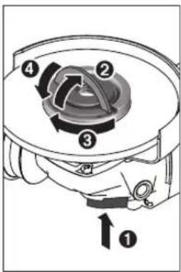
Tericety winnHdieni (3)
6eKity yuH uHHdenbdi
6eKity tyMecin 6acbHb3.
Xblnam TapTkbl
comblbl (14) 6eKity yuH
Xblnam TapTkbl COMBn
INMerIH KOFapbifa Kaibpbl
Xblnam TapTkbl
comblbl cafat TImeh
KaTbIb 6ypaHb3. INMeKTi
Xblnam TapTkbl
comblbl 6eKity yuH
TeMeHre KaibpbHb3. Dnck
WetInde TapTbn KOIO
Xetepnik emc.
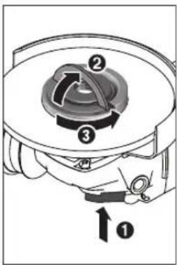
Tnicti peTe 6ekitiren,
3aKbIMdAmfah KblIdAm
TapTkBll COMBIHdb1 (14)
KOMEN 6ocatyfa 6oana.
On yuiH XblI dAM TAPkBll
COMBIHHbIH INMerIH
KOFapbHa KaibpBII
XblI dAM TApTkBll
COMBIHbI CaFt TiIne
Kapcb KaTb6paHb3.
EkaaH aKaTbI
6bekmeJreH XblJa
TAPkBll COMBIHdb
acannneH 6ocatnaHb3,eki
6yipnik Teciri 6ap combl
KintiH naIaIaNbIbI3.
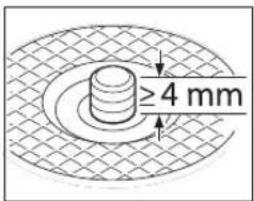
Kbickbiw fnaheu nen
aXkapay/kecy dncicin
opHaTKaHH coH axapay
wnHdienHH 6oc 6ypaHda
y3bHdbfB keminHe 4MM
bonybl Tnic.
Akapay acnabHbH KaTbI
TypybHa Ke3 KETki3iH3,
Ocbnai on 3neKtp KpaIbIbIH WbIFbcIHda WINHdEnDeH WbHbIK Ketnei.
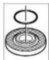
Optafa KeTipeTih 6byrTKIH TipeK fnaheiHHe (12) nactMacc6bIeK (dHreKeK KIMacbl 6ap caKHa) 6ap. DeHreKeK KIMacbl 6ap CaKHa JOK HeMece 3aKbIMdaFah GOnca, apkapanaianaHbanytpbn TipeK
fnaheuTi (12)MiHdTeTI Tpyde aybIcTbpy KepeK.
Terictey KypanbH opHaTkaHHa KeiH Kocy anDbHda opHATydbH dpybCTbFbH XeHe KypandbH epKIn aHaHaTaBHBn TEkcepH3. Terictey Kypanbl
291 Ka3aK
Kopfabi KaTamaF aKeH 6aKa 6eKeTpRe yKeIeMaeHaHbIn KAtKaHbHa Ke3 KeTki3iH3.
Kennyiupaipidericteyweh6epi
Xennyiu Tapi3di terictey weh6epimen kymbictap yin h apkaan H kon KoprafbibH (20) KNIH3.
Pe3eHke tericTey tApEnKeci
Pe3eHKe tericTey TepenKecimEn (21) Kymbictap yuH apKaawan Kon KopFaBbiuHn (20)KnHj3.
Opnat pyi cypetep 6ap 6eTKepcetinreH.
Pe3eHKeEN JxacanfAH axapnay TaepenKecin (21) axkapny HnnHdieniHe (19) KblNkblHb3.
Akapnay nckicin (22)pe3eHke axkapnay TpenkeciH (21) actbHa 6acbHb3.
DHeREnK CombHDbI (23) OPhaTbHbIx He Eke 6yInpNIk Teciri 6ap DeHReK CombHdApFa apHaNfA KInTne 6ekmdeH3.
TocTaFaH Tepi3i KbInWBk/JdNckinik KbInWBk
Toctcafah Tapi3di Kbiinbiknenn Kymbictap yuH apkaaah kon Koprafbibh (20) khiH3.
Ophaty petiypeTep 6ap 6eTe Kepcetiren.
TocTaFAH Tepi3di Kblwak/Dnckinik KbIwakTbI WnHHenBfe WnHHenb fnaheci WnHHenb IpeK OImacBaHa TbIb3 TaKanbl TpyaBihdai Bypan Bekiry Kepek. AByp Tepi3di KInTNHe TOCTaFAH Tepi3di/Dnckinik KaIWBtBfBeKemDeH3.
KaTbI KOpBItNa ToCTaFaH Tepi3I TericTey Weh6epi
ToctaHaTepi3di axapnay dncicin TeK cekecti Kopfabwu Kantamamen na dananyfa 6onably.
Kapamdbiterictey Kypanbl
OcbHyckaynbkTa KOFapbda atan etinreH apnbK terictey Kypandabhi naDanahyfa bonaibi.
NanahbIaTH terictey kypanapbHbH pyKcat etiren
aHaJIbIMap cAhb [MnH] HeMece aHaNy KblJaMaDfbl
[M/c] TemeHe 6epinre KeCTeeri MAndepEn TeMeH
60JmaybKepek.
CoHbKTHericTey KpaIbHbH JxacbcipMacbiHa Kepcetireh pyKcat etireh aHaBIMap caHbH HeMece aHany bIdaMbIfbH CaTaHb3.
| MaKc. [MM] [MM] | ||||
| D b d [MHH | 1) [M/c] | |||
| 100 | 7 | 16 | 9000 | 80 |
| 115 | 7 | 22,2 | 9000 | 80 |
| 125 | 7 | 22,2 | 9000 | 80 |
| 150 | 7 | 22,2 | 7500 | 80 |
| 100 | - | - | 9000 | 80 |
| 115 | - | - | 9000 | 80 |
| 125 | - | - | 9000 | 80 |
| 150 | - | - | 7500 | 80 |
MaKC. [MM] [MM]
Dbd [mH

7530M14900045
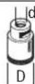
82-M14900080
PeykTopnbik 6actbl 6ypay (GWS 18V-10 C)
AkkymyIHTOpbl 3neKtp KpaIImen Ke3 KeIReH XMybIcTapbl (MbIcIbI, opHaTy, KbI3MeT KepCeTy, T.6.) 6actay andbIHda, coHdai-ak, 3neKtp KpaIbnb TaBIMaIaNay XHe CaTay Ke3Ine duFapbHbI3.
Kocb/0uipriuke Ke3deNcoK TIO XapakattHy KayinH TydbpaDb.
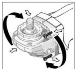
PeYkTopb6actneKTI 90 Kaammen 6bypa7a6nabl. Ocbni Kockbiw/eWiPriwi apHaBbXyMbIC
JaHaapbHa, MlcAnbl coaKaHnap yuH OHtaHb6 Bacapy KyHe KeTpyre 60ana.
46paHnHaHbTOnbIFbIMeH 6paHbocaTBH3.
PeykTopb6actb Kopnyctah anMaCTAHKaHa KyIe Kaan 6bybH3.4 ypaHdaHb 6epik 6ekitih3.
UaHdbI JxHeJxOHKaIapDbI copy
KopacbH 60ny, Ke6ip aara copTapbl, MHeepaIap XHe MeTannap 6ap Ke6ip MaTePnAanapB1h WAnbl DeHCaybKa 3nHNbbl 60ny MyMknH. WaHa TIO XHe WAnbl Kty naJaAnahyUbda Hemece XaHbHdAflb IaAMdApda anepeprnBk peakunapbpXHe/Hemec EtbHc KOndApbHbH aypynapbH TybpybMyMKIN.
Keibip wah Typepi, acepece eme Hxhe wamwat aafbihhwaHbi, acipece, aafTb eHey kAnkbkaptbimEn (xpomat, aafTb Kopfay 3a)6ipre KaHeporeHep 60bn ecentenei. Acbcetik matepnaTek KaHa MaMaHapMeH enDenyi kepek.
KymbocOpbHbHJKaKcbJKeJeTeiYiHe Ke3KeTki3iHj3.
-P2 cy3i cblbInhdafbra3KaFapdb naDanaHyycblnabdi.
HneTIN MATEpnaIap YwIH eniHj3e KOndaHbIaNtBnYfapbIMapdbI naDaIaNbHbI3.
KymbocpbiHaWahBbH KHHaMbayi KaFanaHb3. WAn OHaTayHyb MykH.
PaindanaHy
Taindanahya ehdpy
AkkymyTopdbI ophaty
3apraTaNFAH aKKMyNtOpDb (8) anDbHaH 3Jektp KpyaBbHbTHyTKacbHa aKKMyNtOp 6ekm 6byFaTaNFAhBHaCaBbHb3.
Kocy/ewipy
3neKtp KypaunbIH Icke Kocy ywiH Kockbl/owipriuT (6) aIFA kblkbblb3.
Kockbiw/ewipriwi (6) ophyyin Kockbiw/ewipriwi (6) TEmHe ripeiree 6acbHb3.
3neKtp KpaBnH eupiy yuiH, KockbIw/ewipriwi (6) xi6epin Hemece on 6eKITINREh 6onca KockbIw/ewipriwi (6) kbcka apTbHda TEmeh 6acbin cocbiH xi6epiH3.
Painananyan anbih axapnay KypanapbH KaTateKcepiiz. Axapnay Kypanbl 6epik ophaibin, eW Keepric3 aHanybi KaKeT. 1MHyt iHIne cbHay Kymbcih xkytemeci3 opbHaBb3. Akaybl 6ap, Domanaekemec Xane dipindein Haxapnay KypanapbH nainanah6aHb3. By3bnfA hxpapny Kypanapblxkapbln, 3akimapfa anbl KenyIMKMH.
KepicokkkiKeiHderi oipyxyneci

3neKtp KpaIbI KeHET Kepi cokca, MbIcIbI, keCetIH KepIe cbIIhAnHy Ke3InDe, Ko3fantkbIka Kyat bepy ToKtAtbIaDbI. OHJa KaBkIOHTbIK YMbIC WAmbl (4) aK TYCTe an KyKePCETKIi (35) KbIbI TYCTe XHaHdbI.
KaTaNananaHywHAnkblapKbIbTb6)ewipinre KnyRe KeTIpIn,3NEKTpypanbiH KaTaNocbl3.
KaetaKo3ranycaTarlblbl
Ke3eIcOK KocbIydaH KopfAbl WkaTaNDbIpydAn KeHH 3neKtp KypalbIbH 6aKbIaycbI icke Kocblvih 6oNlbPmaIbI.
KaIa Icke KocbIyduH KopFaHbIc 6bceneHdi 6oIca KyI KepcTeKiU (35) Kbl3bl Tcyte KaHaAbl.
KaTaNananyuin axkbpatkbIbI (6)ewipireh Kyire KENTIPIN 3neKtp KypaPdbl KaTaNKOcbHbI3.
Karblinyda euy
Kipictipinren KaBnyda eWy 3eKtp Kypanb Jkepre TycKeHne OHbe eipedi. OHda Kyk Kepcetkiu (35) Kb3bn Tcyte Kblnb/blaTaNbI. KaTn naDAnany ywn AxbpatkbWtB1 (6) eipinren KYre KeTinp 3eKtp Kypanb KaTa Kocblb3.
TainananybHnHTepfeci(DcypetIHkapaHb13)
PnndananyhblnHTeppeci(5)3neKtp KypalbHn
aHaBmdp caBH anDbH aIa TaHdayFa KHe KyH KepyRe
KMeKTEcedi.
AHaHbIMdap caHbH anDbH ana TaHday (GWS 18V-10 SC)
AHaIbIMap caHbIH anIbIH ana TaHay TyIeMecImeH (34) KepeKti aHaIbIMap caHbIH Kymblc icTeReH Ke3Ne de anIbIH ana TaHayfa 6oIaIb. TeMeHderi kectede ycbHbIFra HKeemep 6epinreH.
| Materiel Panzaanany Kymbics Kypalib AhaHbImdap | ||||
| caHbH anDbH anaTahdav backbHb | GWS 18V-10 SC(100/115/125 MM)[mH-1] | GWS 18V-10 SC(150 MM)[mH-1] | ||
| Metan Kbylsskpen EHHey, TOTbI KeTipy | ToctarH Tepi3diKbllsak | 14500 4000 | ||
| Tot6acnaiTbIH6onat | Axkapnay FnbpaBikshai6a 2 6000 5500 | |||
| Metan Cbylbip terictey terictey shen6epi 3 9000 7500 | ||||
| Metan Kecy terictey shen6epi 3 9000 7500 | ||||
| Tac Kecy AnMaCTbIK keCy | weH6epi Jxane6aBbTaybHtarp (tayXbHbICTapbHtek6aBbTaybHtarpMeHNbire Kecyre6oJadBi) | 3 9000 7500 | ||
Bepinre anHaIbIMdap caHbIHmHedepei 6aftTama mHdep 6onadbl.
Kymbic Kypanbl aHnblmDapbHbH yFapbHbI caHbl 3neKtp-KypanblHa-KepcetInrEH MaKCHMaNbl
aHaIbIMap caHbHa-Teh-6onyb-Kepek. Ecentenre HbIaMdbfHbHaHTeisiPeKICTenTyPAH KepeK-KapaKaTap cbHyb, yBbN KeTyI MyMKH.
294Kazak
Ky KcpctkiuTrepi
AkkymyTOp 3aprTay MaBnacb/ce6e6i IeWimi KyinH KepcetKiwi (naDanhyu bI nHTepfeci) (32)
Kacbl AkkymyTOp 3apTaNfA
capbAkkymyIaTOp 9epnik 6oc AkkymyIaTOpdbI kblIaam aImactbpy Hemece
3apraTay
KbI3bln AkkymnyTop 6oc AkkymnyTopdbI anMaTbIpy HeMece 3aprTaay
Aptbik kxykTeeny KopFaHbcbl MaBlnacbl/ce6e6i Wewimi Kepcetkiwi (36)
capbI UeKtik TemnepaTpya Ketindi (motop, 3neKtpoHnKa, aKKyMnyTOp)
3nektp kpaibin 6oc kypicte icetin, cytbihb3
Kb3bn 3neKtp Kypan Kb3bn KeTKeH, con ce6enteh
3neKtp KypaBih CybTbHb3
3NeKtp KypanbHbH Kyi MaBbHaCbI/c6e6i ZeWiIMi KepcTeKiwi (35)
Kacbl Kyi OK -
capbI IeKtik TemnepaTpy XetinHHeMece aKKyMnyTOp 6oc
3neKtp KpaIbH 6oc Jypicte ictetin, cybltbHb3 HeMece aKKyMnTOpDb IkbIaAM anMaCTbPbHb3 He 6oNMa ca 3apraTaHb3
Kb3bn TycTe XaHaBbl 3neKtp Kpyanbl Kb3bn KeTKeHemece aKKymyIrp06ocafah
3neKtp KypaIbH cybltbH3 Hemece aKKyMnTOpbl aImaTbPbHb3 He 3apraTaHb3
Kb3bIn TycTe XbInbInkTaIbI Kepi Cofy eWyi, KaTt Aicke KocblnydAn KopFay HEmece KaBlynda eWiy icKe Kocblnbl
3nEkp KypalbH Eipin KaTaNKocbHb3
Kek KblbIbIbKaIbI 3neKtp KypaIbMo6HbIe TepMHaImeH 6aHnabIcTa Hemece npaMeTpnp eTki3inIn Typ
BaihaicyHKnnaapbI
Bluetooth Low Energy Module GCY 30-4 baHaNbICTb TEmHeIe bHaNbIc fyHKunnapbI 3JekTp Kypanbl yuH KONKetIMdi 6oNabl:
Tipkey kaneapanay
-KyHIn TeKepy, eCKeTpY xa6apnabHy IbIfApy
Kannb mniMeTep men npametnpep
-Backapy
Bluetooth Low Energy Module GCY 30-4 typanb Manimet any yuiin jinhakTaBn naDanaHy KcaynbHObkbl3.
Painanany Hcyaynapbi
3NeKtp KypanbOpHaTbInFaH BluteothLow Energy Module GCY 30-4 MoynimEn padnohntepFeinen Ka6dbkTaFAn.KepriniKi nainanany wekeynepi, Mbicbl, ywakTapda Hemece emxhaHanapda eckepiiz3.
TipeK Ka6bipFanapda OmbiKTap XacaFaHda a6aHaNbI3, «CtAnKa TpyanbI HycKaynap» TapaybIH KapaHbI3.
CanMaTbI TypaKbI KaNbIbTI KaMTaMaCbI3 eTnece, TaHbIHdAmHb6ekitih.
3neKtp KypanFa TOKTaraHwa XyKTeMe TycipMeH3.
KorapbI KxYKeMeEN KeIN 3eKtp KypanDbH 6ipa3 cankbHdAbybHa, 6ipHeWe MmHyT 6oc XypicTe XymbcI cteyiHE MyMknHik 6epiH3.
3NeKtp Kypanbla6pa3nBTi-KeCy cTaanHaanda naDanaHbI3.
Tericty KHe Kecy Dnckinepihe cybfraHua TMHei3. 1e6epnp XMybIC Ke3iHne Kbl3aBl.
Erep3neKtp KypaIbI 3neKtpoCTaHkAbl peTte 3aprtanca, opHaTbIFaH 3neKtpOHHKa 3neKtp KypaBIn eWipedi. 3neKtp KypaBn KaIta Icke Kocy yuH KockbI/ewipriiTi (6) 6acblb3.
Cbubipin Terictey
Ewkaan Kecy weh6epnepin cbdbipbin TericTey yuH naDanaH6aHbI3.
30°-40° WENBep 6pybIbIMe CbIDbpIN TericTey KezIHnEH JAKCbHtNKepe npFa 6oana.3neKtp KpAaNbJkaan6acbln, anfa Xane apKaXbINkBtBnB3.Byn Ke3e
daBnHaMa TaM KaTb Kbl36aNb, TyCIn e3reptnei XeHe apHaIap naJa 6oMaNbI.
Kennyiu TApiai terictey weepepi
Kenniyu Tapi3i Tereictey Wen6epimn (Kypan) cohbuIme 6ipre deHec betepni XHe npoepnIbepPi de eHdyeTe 60ana.
XenniyuTapi3di terictey weh6bpneip aetteri terictey weh6bpneipemeh canbictbipFaHa y3aBipak Kbl3MeTeedi, a3bipak wuy bIrapabj xHe terictey tempepatacbl a3bipak 60nabbl.
Metanapdbkec
BaihaictbI abpa3nBtep Kemerimeh Kecy yuH npKaaHaN Kecyre apHanfah KanTaMaHbI naDanaHbIbI3.(16)
Tericey weh6epimeh keckeHde bipkenki, MaTePnAn yuHIn Dpybc6epymenKyMbIC icTeH3. Kcyweh6epine KbcBIM TycipMeH3, OHb eHKeITneH3 XaHe WaKaMaHBi3. Byipnik KbcBIMMe aHaHaFaHBiHa Kecy weh6epin TOkTaTnAbI3.
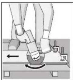
3nektp Kypanblbepkawah aHany6abftbHaKepi kypri3y kepeK. OHTNECE 6akbnaycb3 Keinren Hkepenh sbbyfkyain TYbHdaiB1.
IpoΦnIbIepdI Hemece TepKbIpbKy6blpnapbl Kecy KeiHne KecyIe en a3 KcIeHeH KIma da 6acTaHb3.
TacTbI Kecy (C cypetih kapaHbi3)
Tactbkeckenhe daHHbIH KETKINIKTI copbinybH KaMTamacbI3 etiH3.
WahyTKbiMMAckacbiHKnH3.
Byn 3neKtp Kypanbl TeK KpyrKa Kecy/KpyrKa TericTey yin naiDanahya 6onabl.
Tactb kecy yuih anlmac kecy dickinepi nai daanahf an H. Baftaybtlap 6ap kopfaibk kantamaHb (30) na danany yuih tac wabih copin any yuih wachopfbt bna danany kepek.Bosch ocbiHd aanhcopfbtapdycbiHaDb.
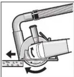
3NeKtp KpaTbEwipH3
KHe 6aftTaybIITapBbH
anBnFb6enirim
6eWke opHaTbHb3.
3NeKtp KpaTb6ipKeKi,
MatepnaIra caKeC
6epyMeH XblkbTbHb3.
KpaMbHa KaTb
0eKe nca KaTb
MatepnaIapDb,Micanbl,
6eToHdb, eHcy Ke3iHne IAmac WeH6ep KblbI Ketyi XaHe 3aKbIMdanybl MyMKIn. AnMac WEn6epderiyuWbHap ocblb6inipedi.
ByjXaJnJaJaXyMbIcTbTOKTaTbHb3 XHe aImac Weh6eppi 6ocXyPicte,ehXoFapblXbINdAmdbkTaKbickaYaBbIT60b1 caNkbHdaTbHb3.
OHHIMINIKTHaHTapbIKTaNMeHDeyJxHeYKbIHdAp anMac Kecy ueHBepei eTnc 60bnKanFaHbH 6inipei. OHbl abpa3nBTi MaTePnaJa, MbCanb, CInNKat KipniUte, KckAaKeCy apKbInbEtkipNeYe 60nAbI.
Ctathka Tpyanbl Hcykaynap
TipeKa6biprafapdaftbOblkTapFa DIN 1053 HOpMaCbHbIH T TapMaFbHemece caiKec eJneri epexe KOnDaHbIaNab. ByN Hcaynapdb MinTeTI Type opBihday Kepe. Xymbctb Bactamac 6ypbH ctaTnka JxHnderi MaMaHMe, CayetWimEn Hemece npopabneh keheci3.
AkkymyIaTOpbl OHTaIbI naIdaNHy typanbl Hcykaynap
AkkymyIATOpIbI CyIbIKTbIKTapdAn JHe bINFaIaH KOPFaHbI3.
AkkymyIaTOpBbTeK-20°-50°C TempePaTy aYkbMbHnDa CaKaTaHb3.AkkymyIaTOpBbJa3aKeNikTe KaNDbPmHaB3.
AkkymyTOpdbH XenDety TecirH MyMcaK, Ta3a XeHe Kypfak KbilIwakneH MyKHT Ta3aIahbI3.
Painanany Mepriminai TaTapkayb AAKymyaTopdbH eckipreHH Xahe aybictbipy KepeKtiH 6inipedi.
KokbictapdaKaetaeHnyTypanbyHyckaynapdbOpbHaB13.
TexHHKaJIbIK KYTIM XKHe KbI3MeT
Kb13MeT KepcTey XaHe Ta3anay
Akkymnatopdb3neKtp KypammeKe3 KeIReH Xymbictapdb(MblicabI,OpHATy,KbI3MeT KepceTy, T.6.) 6actay andbHa, cohdai-ak, 3neKtp Kypandb TaCbImaJdAy XHe CaTAY Ke3InDe WbIFrapbHb3.
Kockbiw/ewipriuke Ke3deNcoKTHIO JapaKaTTaHy KayinH Tydbipadbl.
Kacbi apicehimdi kymbc ictey yuih 3nektpr Kypanbmi MeH XeIeTkiu TecikTi Ta3a ycTaNb13.
KabTAPbMyKnATCaKaTaH3XHeKytH3.
TybHybIfa Kbl3Met Kepcety XaHe naDanahy Kehectepi
Kb3met KepcTe W6ebpXanacBt EhimDi XeHDey XeHKeY Kty, coHdai-ak KocAnBb 6nIweKteP typaIb cypaTapFa Xayan 6pei. Kapby cb3bnapbMe HocAnBb 6nWeKteP typaIb mIImEeTpePi TEmHeeri MeekKaJa Ta6acbi3:
www.bosch-pt.com
Bosch 6aIapnAmacbKeHecTob6bi3inEhimepKane onapbIn KepeK-KapaKTapbI TypaKTapbHb3ra Kayaan 6epei.
CypakTap KOJO XeHKeKocankb6enweKTepeTancbIpc6epy Ke3iHne MiHdETTI TpyeEHIMDIN 3aybITbIK TaKaTAAcbIHdafb10-caHdbE HIM HEMipIN Ka3bHb3.
HniPi TanaTapbMeH HopMaapbHbH CaKaTaNbMeH 3nEeKpyaBn HKeHDey KHe KeNinDki Kbi3MeT KepcTe
296 Romana
6apbik MemkeTep ayMaBihDa TeK "Po6ep Boi"
HpmaBik Hemece ABTop3aunnaHafn Kbi3met Kepcety
optaBkTapbHaOpbHdaIa. ECKEPTY! 3aHcb3XoJIMeH
ekinireh eHimdepi naHanaHy Kayinti, deHcaynbfbH3ra
3HH KeTIpyi MyMkiN. OhIMdepJ3 aHcb3Xacay XeHe
tapaty ekimwiniKxHe KblmbCTbK Tertin BoBHwa
3aHMeN KydaHaHa.
Kazakctan
TybinybnapraKehec6epyXaHaBmApdbkaBnay optanbIfb:
"PoBepr Bow"(Robert Bosch) KUJC
AMMaTbK
Ka3akctan Pecny6nKacb
050012
Mypat6aeB K., 180 yu
"TePmec" 50,7 ka6aT
Ten.: +7 (727) 331 3100
a_Kc: + 7 (727) 2330787
E-Mail: ptka@bosch.com
CepBntK kbl3Met Kepcety optanbikTapbMeH Ka6blnday nyHKTePiH MeKeH-KaNbTypaNbTOnbIKKaHe e3Ekl aKnapaattb Ciz: www.bosch-professional.kz pecmnc aHTtah ana anacbi3
Tacbimanay
BnHnHNOHbIK AkkMyIaTOpNap Kayinti TayapnapFa KOblnTaBH TaanTapra ca 6onyb Kepe. PaiaIaNHyu bI aKkMyIaTOpNapBKeWeDe KcBIMsa KyKaTTapcb3 TaBImaIaIaIbI.
YiuiHui Tynfnap (Mbcanb, eye Keiniri Hemece Xibepy) opamafKaXeHe MapkAnapfa KOnbInaTbH apHaBt TanaTapdbCaKdTay Kepe. XibepyRe DaBHydAy Ke3iHne KayinTi KkyTepPi TaBImaNlay MaMaHbEmn Xabapnacy KepeK.
AkkymyIaTOpIbKOpNcbl3akbIMdaIaHb60ncaFaHa
k6epiH3.AuBkTyrnicnepiJxenimdeH3XHe
aKKMyIaTOpBlOpamadaKo3fAmMaTbHdApHaB3.KaKET
60nca,KocbIMuaYTTbIKepexepePi caKaTaHb3.
Kadere kapaTy

3NeKtp Kypaandapdbi, AKKyMyIaTOpnapdbi, KepeK-JapaKaTapdbi JKeHe opay MaTePnAanpaBih EKONOIRNbIK TypFbIaH
Dpybc yTHnH3aunnaJlayfTaTncbIpy KepeK

3NeKtp Kypanapbl JxHe
aKKyMnyTopnapbl/6atapeepnapbl Y
KOKblcHbHa TactaMaHbI!
Tek kaHa EO enepi yuin:
Eypona 2012/19/EU epekeci 6oBbHua japaMcb3 3neKtp KpaIapblx kHe Eypona 2006/66/EC epekeci 6oBbHua 3aKbIMdaFah HeMece ecki akkymnyTop/baTapeenap 6eKk KHaBbIN KaDeE JapaTbNyI KaKet.
AkkymytnaTopnap/6aTapeennap:
JIHTHNOHBK:
TacbMaJday6nimiHneriHyckaynapdbOpbHdaB3 (KapaHb3,TacbMaJday",BeT296).
Româna
Instruţiuni de siguranta
Service scule electric
Strada Horia Macelariu Nr. 30-34, sector 1
013937 Bucuresti
non3BaHeTo Ha eneKtpOnHcTpymEnTH 3a pa3nHnO T npEbnDeneHTE O npOn3BOHNTen I npINOKeHnIOBnA Ba OnaCHOCTTA OT Bb3HNKBaHe HA TpyOBn 3nOIOnyKn.
PnKxNBO OTHoWeHne KbMaKymNaTOpHN eneKTponHcTpymEnTH
3a 3apekdaheTo h akymynatopHnte 6atepnn H3non-3BaIte cmo 3apndHnte yctpoichTBa, npenopbuaHHOT npon3BODHTe. Korato n3non3BaTe 3apdHn yctpoiCTBa 3a 3apekdaHe Ha HeNoDxOJaHn akymyatopHn 6atepn, cbjcETByBa ONACHOt OT Bb3HNKBaHe H noXkap.
3a 3axpaHbAe Ha eneKtpOnHcTpymEtHe H3non3BaIe Camo PpeBnEHeHte 3a CbOTBeTHMa Moen aKyMyatopn6 BateHH. H3non3BaHTo Ha pa3nnuHa akyMynatopn6 bateHH moKe da ppeH3BnKa TpyOba 3noN0nyka H/nn noXap.
Pepna3BaIte HeN3nON3BaHHTe akyMnyaTOpH6aTepeHHOT KOHTAOK T CROEMH HIN MANK METAHN PpeMeTH, HApN. KNaMepH, MOHeTH, KIOUOBE, NPOHOH, BHTOBHAPII., TbKATO TE MORAT Da PpeHN3BHKat KbCOcbEeHHeHNE. IocJeCTBnRA To KbCOTO CbeHHeHMe MORAT Da 6bDat n3rapnHn Hn noXap.
PnHnnpabHHNo H3noN3BaHe OAKymyataOpHa6aTepeHrOHTe MoKe Da H3teue eEnkTPOHn. H36raBte KOHTAKTa C Hero.AKO BbIpeKn TOBa Ha KOKaTa BN noNaHne eneKTPoHn, H3nnakHe TmCTOTo 0bHNO C BOJa.AKO eEnkTPOHn IonoHne B OHTe Bn, cNeH e3a6aBHO 0bHNO H3nnakBAHe NtbpCte NOMou OT neKap.EeKTPoHnTbMooKe Da npedn3BnKa H3rapHHHa KOXATA.
TpoDbpxkane
Дунсайтpe moThtHa eNeKtpOnHcTpymeHTe Bn Da ce N3BbPbBa cMo OT KBaHΦuHpaHcneuaHnCTHcMo C N3N03BaHTo HaOpHnHaHHpe3epBHN qactn.ПоТиHaHHce rapaHTnpaCbxpaHraBaHe Ha6e3ONaCHOCTTaHa eNEKtpOnHcTpymeHTa.
Yka3aHn3a6e3oNa cha pa6oTa c bTnOuaNn
O6uynka3aHn 3a 6e3oNaCHOCT npn uHNOBaHe, uHNOBaHe c uKypKa, noHCTBaHe c TeHeHH YeTKn Hn a6pa3HBHO pHaHe
To3n eEnKTPoHnCTpymeHT e 3aMHCnE H da yHKuHOHpa KaTO uNanΦMaunHa, uKypKa, TeneHa YeTKa HINnHCTpymeHT 3a p3aHe. Ppoetye TcHKn npEynpexDeHH, yka3aHH, 3ano3HaTe Ce C fHyprte HTexHueCKNTe XapaKTepnCTKN, nPHNOKeHN KBm eneKTPoHnCTpymeHTa. Iponyckn pNn cna3BaHeto Ha yka3aHHraTIO-DOy MORaT Da IpeDn3BHKat TOKOB ydp N/ INI TeKKn TpaBMn.
- DeinocTH KATO ONINPAHHe CE npenopbUba Da ce n3BbPWBAT C TO3N ENEKTPONHCTPymENT. DeIOHTA KOIHO TEKEPTPOHNCTPymENTbT He e pEHa3HeueH, MOrTa daNOBIuAT OAnCHOCTTa N da npEni3BnKaT HapaRaBaHna.
He n3non3BaIpe pa60TH HNCTpyMeHT NdoTbHINTeHH pncnoc6nHnKoHT He ca CneuaHnHOpoEeKTHpaHH yTBbpDeHN 3a No3BaHoe OT npOn3BOJNTe
Ha eKtpnHCTpyMeHa.ΦaKbT, Ye daJeHO npnc-noc6BHeNe MoKe Da 6Be MOHTpaHO Ha eKtpnHCTpyMeHa, He rapaHTnpa, Ye paBoTa c Hero e 6e0NaCha.
CkopoCTHa BbPTHe Ha pa60THH NcHTpyMeNT Tp6Ba Da e Hau-MaIKOTO PAHb HA MaKCHMaHnHaTa CkOoCT Ha BbPTHe Ha ENEKTPOnHCTpyMeNTa. Pa60THH NcHTpyMeHTN, KOHTo Ce BbPTT NO-6bp3O OT ppeBnEHOTo, MoTat Da ce pa3pyWAT n Da ce pa3NETT Ha napyeta.
BbHnHnT dHaMeTp H De6eHHnHa Ha pa6oTHn HnCTpymENT Tpa6Ba da 6bDat B rpaHnUte,3a KOHTPOHNCTpymEnTbe npoeKTHpaH. Pa6oTHn HnCTpyMeHTn C HeIOxOJaIpa3MepH He MoarTa 6bDat OcHpyeHn KOHTPOINPAH nPabNHO.
PnncbEHHENTNNT OTBOP C Hape3 Ha akcecoapnt Tp86Ba Da nacBa Ha pe36ata Ha Bana Ha brrnoaHa. 3a pa60TH NHCTPMHTN, MOHTPAH Ha CEHTPOBAuN Phanu, PnncbEHHENTNNT OT BOP Ha npcnnoc6neHMeTO Tp86Ba Da nacBa Ha CEHTPOBAUTo CTbnano Ha Phaneca. Pa60TH NHCTPMHTN, KOHTO He nacBat Ha npncbeHHENTNNTE ENEMEHTN HA ENEKTPOHNCTPMAH, IMat 6nHe, Bn6pnpaCINHO MRAT Da nppeIN3BkAt 3a ry6Ba HA KOHTPOHd ENEKTPOHNCTPMAH.
He n3non3BaIte NOBpeHn pa60THN HNCTpyMeHTn. BnHaH INpeHn ON3BaHne pOBepRABaTe pa60THN HNCTpyMeHT, HAp. a6pa3NBn DnCKOBE 3a OTyNBHn NnyKHAHTHH, NOJNOXKA 3a NyKHATHH NIN N3HOCBaHe, TENEHN YETKN 3a pa3XnABeHN NIN CUYNEHN TEYeTa. AKO eNEKTOPNCHPTyMeTbNT NIN pa60THN HNCTpyMEHT 6bDat H3NYCnatn, Hn POBepRABaTe 3a NOBpeDa NN NON3BAIte Dpyr. CnE KATO cTe npOBepHN MOHTpAHn pa60THN HNCTpyMeT octabete eNEKTOHN HNCTpyMeTA da pa60TH BnpDJIKeHne Ha EaHa MNHYta C MAKCMHnA CKOPoCT Ha BbPteHe, KATO dPxHNe Te ce6e CHn HAmHPaun Ce Na6Hn30 NIna N3BbH paHHATA Na BbPteHe Ha pa60THN HNCTpyMeH. NOpeHn pa60THN HNCTpyMeHTc CE yynATn Hai-ecTo Ipe3 To3n Ipo6eH nepnoi.
Pa6oTe c nHn npEpa3nCpeCTBa. B 3aBHCnMoCT OT KOHKpETHHe YcN0Bn H3NON3BaHTe UHa MacKa 3a Nnue, 3aunTa Ha Ouyte Hnn npEpa3nO uOyna. AKe e Heo6xOmo, pa6oTe c npOTbONpXOBa MaCKa, yMOn3aRnyuHTen (aHTnFOH), pbKABuHn pa6Otha pIpcTnKA, KOrTo e B CbctOAHne Da cnpe OTxBbPauHN MAnKn ABpa3nBnHnpAeuHua. Ouyte Tp8BaDa ca npEpa3eH ON dpeBn NapuHua, KOtO MoRat da OTHbPcTnNo BpeMe Ha pa6ota. IpoTbONpaxOBa Hn DHXATEHATA Macka Tp8Ba Da Morat da fHNTpHpaT B3HHKBAuH No BpeMe Ha pa6ota. Ako npDblKnTeHNO BpeMe CTE HIOXeHn HA B3DeHCTBHeTO Ha CINENyWM, MOxete Da npETbPntne YactNuHa 3ary6a Ha cnyx.
DpBkTeHAMpaunCeHa6n3oNuaHa6e3onacHO pa3ctOHHeOTpa60THATA30Ha.BceK,koToCe HA-MnPA Bpa60THATA 30Ha,Tpr6Ba Da HOCH NnHn PpeA HnHn CKeOpCT N Da pNnHHT HapAHraHHn H3BBn HnncpeCTBeHATA 30Ha Ha pa60Ta.
Korato n3mbnbaTe onepaun, npKoTc sbuectByBa onaCHOCT pa60THHt HNCTpymeHT MoKe Da 3aceHcCKPHT NOd NOBbpxHOCTa IPOBODHNu NOd HAnpeKeHne,doHNpaTe enEKTPOHHCTpyMeHT CaMo O eNEKToPONHpaHNTe NOBbPxHocTH HaPBkoXBATKHte. PnKoHTaHT Ha pexeun Akcecoap C npOboHNk NOd HAnpeKeHne E Bb3MOXHO HANpeKeHneTo da ce npedeNo MeTaNHHe DetAaHn Ha eNEKTOHNCTpyMeHT N TOBA da npedIN3BnKa TOKOB yApd.
HnKora He octabHe e nektponhctpymEnTa npedn BbPteHeTo Da e cnpno HanbNo. BbPTaIurT ce paboTe HnHCTpymEn MOKe Da IOnpe NOBpxHOCTTa N da yckoPn HEKOHTPOINpHaO e nekTPOHNCTpymEnTa.
He BkIIOUBAHTe eNekTPOHHCTPymEna,doKato ro HOcnte,obbpHAT KbM Bac.CnyuaeH DoINp Do BbTpAunCe paBotoH HnCTPymEHT MOKe Da yBNepe DpExTe Bu npaoTHnRT HnCTPymEHT Da Bu HapaHn.
PepnoHNo NOuchBaTBe BENTnAuzHOHHTe OTBOP Ha eNKTponHCTpymEnTa. BeHTnAtOpbHa eNKTpO-BnIaTeIa3acMykBA npax, aOTnaHaTo Ha MeTaNpax NIO BbTpueHOCTa HA KOpIyCa MoKeJa npeDnBnKa onac-HoCT OT TOKOB yAp.
He pa6oTe c e nEeKToHnHcTpymenta B 6nH3OCTdo IecHO3aIaIHHMaTepeHaH. NckpMOrat Da BB3nnaMeHrT Te3n MaTepaHn.
HeH3NON3BaIte pa60TH HnCTpyMeHT n npncnoc6- HeHH, KOHTo H3NCKBAT TeHO OxJaDAhe. Nt3BaHTo Ha BOda Hn DpyT TeEH peAEHT MoKeJa PpeH3BnKa Kb-CbEHNHeHne Hn TOKOB YdAp.
OTkat HauHHHa 36raBaHTo My
OTkaeBHe3aHa peakua BCnctBne Ha 6NOKpuhe HnH 3aKnHbAe Ha BbptTtue Ce abpaunBeH nck, POnIOxeh DnCK, TeneHa YcKa HmDpyr pa6OteH HnCTpymeHT. 3aKnHBAHeTo Hn6KoPaeH TopeH3BkBA BHe3aHnHO CnnpaHe Ha BbPTuHce Pa6OteH HnCTpymeHT, KOeTO OT CB0r CTAHa npEIN3BKNBa HeKoHTpOInpaho p3K0y cKOpraBaHe Ha enektPOINHCTpymeHT B Nocoka, O6pTaHa Ha BbptTeHTo Ha pa6Otn HA HnCTpymeHT B TOokata Ha 6NOKpuHe.
Ako Hap. abpa3HBEN dNCK ce 3aknnnHnHn60knpaB TaTnla, cactTa ot pb6a Ha nCkca, KOToCe Bp3BaB DeTaN, MoKeJa cE Bpeke P3Ko B NOBbPxHOCTT, BCNEcTBne Ha KOeTO DNCKbT da OTCKOu CNHIO. NcKbT ce yCKOPaBA KbM paBoTeUnc CeneKtponHCTPymEna HnB ObpaTHa NocOKa B 3ABNCMOCT TO TOBA B KAKBa NOCOKa E dBHXeHNeto MY B ToKATA ha 3aknnHbae. B TAKBa CnyuAn abpa3NBHTe NICKOBe MORAT Da CE Cyynr.
OTKaTbB3HKNBA KATO CIEcDCTBNE OT HEnPabINHO HIN NORpeWHO NOI3BaHe H eEeKTPoHNCTpyMeHTa M OKe Da 6bDeH36erHat Upe3 noXoJnnpEJa3H MePK, KaTTo eONNcaHo No-dony.
ДрькTe eEnkTpOHnCTpyMeHa BnHaH3dpaBO HnoIbPkaTe NOnuHa TAnOTo H Na PbCuTe Cn, npH KoIrTO ue MoKTe eEeKTHBHO da IpOTNbOCToHte HaEBENTaHNO Bb3HHKHAN OTKat. BnHaHn ON3BaHTeCNOMaTateHATA pbXOKBtKa, aKO HMa TaKaBa, 3a DaMOKETe B MaKCHMaHn CHteneH da OBNaDeTe OTkataHIN PeAKUHOHHM OMeH TpN BKInOuBaHe. Ako 6bDat
314 |Блгарский
B3eTN PNOxOAnu PnpENaHn MepKn, paOteuNt C eNEKToPONHCTpyMeNTa MoKe Da npOTNbOCTOn Ha peAKU-OHHN MOMENT Nn HA OTKaT.
HnKora He npbXte pueTe CN B 6n30ct Do BpTuaCe pa6oTe HnCTpyMeHT MoKe Da BN HapaHi.
He npkTe TnOTo Cn B 30Ha, B KOrTo eNeKtpOnHCTpyMeHTbT ue 6bJe HxBbpEn npEeBHTyaneH OTKaT.
OTkaTt ue yckopn enektponHcTpymeHTa B nocoka,ob- paTHa Ha DnBxKeHneTo Ha paB0THn HcTpymeHT B ToKata Ha 6nOKnpaHe.
BbTe H3KIOUHTENHO BHIMATEHNN, KORAto pa6oHTHe Bbrnnoctpn pb6OBe HAp.n. 36aRBaIte p3KOTOBp3BaHe Ha dNcKa. Brnte, OCTPte pb6OBe nH pr3-KOTo Bp3BaHe ca npEINOCTABka 3a 3aKnHBAHe Ha pa60THnHnCTpymEn H3ary6aHa KOHTpon nHnOTkat.
He MoHTnpaItepeXeEaBepHra,Φpe3epnnnDnckoBe cbc 3b6n.TaKINBa HNCTpyMeHTn PpeHN3BKNBbAT YecToOTKat N3ary6ha HA KOHTpO.
PpeynpeKdHn3a6e3oNaChocT, cneuΦnHn 3a DeHocn no WnfoBaHe n a6pa3NBHO p3aHe
H3non3BaIe cAmO nckOBe, npenopbuaHN 3a BaWn eektpoHHCTpyMeHT, H perepaH, npoeKTHpAHN3a CbotBETHTe nckOBe. NCKOBe, 3a KOHTo eneKTPoHHCTpyMeHT He e npedHa3HaueH, He MoT a 6bTa06e30anaceHn aKeBHOn Ca OnacHn.
Pa60THATA NOBbpxHOCT Ha EKcEHTpKNOB a6pa3HBEN HnCK Tp6Ba Da e cKpNTA B npeNa3Hn HAkpanHK. HenpaBnHMOHTnpaHnCK, KOTo ce noDaBa N3BbH npEpa3HnHaKpaHHK, He MoKe Ja 6bJe o6e3onaceh aekBaTHO.
PperpaTATA Tp6Ba Da 6bJe 3axBaHaTa 3dpaBO KbMeNEKtpoHnCTpyMeNTa N Da E B NO3uN, OCHrpyBaMaKcMnHa H63ONaChOCT, Taka Ye Bb3MOxHO HaMaIka YAcT OT DnCKa Da e CBo6OHa KbM ONepaTopa. PperpaTATA npedna3Ba OpeTopaOT OKbpTBAuN ce NapueHua OT DnCKA, DoINp DO nDCKa No HeBHMmaHne IOT NCKPITe, KOHTO MoTg Da N3TropAT dpexnte.
DnCKOBeTe Tp6Ba Da ce non3Bat cAmo 3a qenHte,3a KOHTo Ca npEHa3HaueHn. HanPmep: He nnHObaH-Te C nck 3a p3aHe. A6pa3nBHnte DnCKOBe 3a pr3aHe ca npEHa3HaueHn 3a OTHEMaHe Ha MaTePnA l Cpb6aHa dnCKa,CTpaHnHo HatoBapBaHe MoKe da Hn CyTn.
BnHaHn3nON3BaIte H3npaBHn KOnTO ca c nOxOJnHΦOpMa n pa3Mepn 3a H36paHn Dnck. POnXoJnHTe PhaHnU yKpeBnAT nCKa N Taka HamaJIbAt onaChocTtA OT CUYINBaHETo My. PhaHnTe 3a DnCKOBe 3a pR3aHe MoKe Da ca pa3NnHnOT PhaHnTe 3a DnCKOBe 3a WnHΦObaHe.
He n3non3BaIte H3HOceHH DnCKOBe OT no-TOEmn bbrnoaHn. NcKOBete, IpeHa3HaueHn 3a no-TOEmn eNEKTPOHnCTpyMeHTn, He ca NOxOJaUN 3a No-BnCOKTe CKOPoCTn Ha BbPteHe Ha MaNKHTe eNEKTPOHnCTpyMeHTn MOrTa da ce pa3pyuWt.
DontbHNTENHH yka3aHH 3a6e3oNaHcOCT, cneuHmHH 3a a6pa3HBNO p3aHe
M36BBAIe 6nOKnPaHe Ha pexeunn Dnck Hn Tbpe CnHNO npTnCKaHe. He n3nblnBaIe npekaneno Bn60Kn cpeOBe. IpTeOBaPbAHeto Ha pexeunn Dnck YBeINuBa CKIOHOCTTa My KbM h3mTaHe Nn 6nOKnpaHe I C TOBa OAnCHOCTTa OTOKat Nn CuynBaHe Ha a6pa- 3NBHN DnCK.
He npkTe TANO CTnpd HnH 3aBbptraunCe
Dnck.AKO npeMeCTBaTe pekeuian DnCK OT Bac Habh, B
Cnyau Ha OKaTENEKPTPOHNCTpyMeHTc BbPrtua CE
DnCK MoKe Da OTCKOHN HENOCpeCTBeHo KbM Bac.
Ako pexeunr dck ce 3aknnn Hnn KORato npekbc Bate pa60ta, h3knoute enektpoHnctpymEna Hro 3aDpbkTe,doKATO NCKbT cnpe da CE BbpTH HaBnHO. HNKORA He ONNTBaHTe Da h3BaHTe BpTaNnCe no HHePUNI DNCK OT Cpe3a,B IpOTHBeH Cnyau MoKe Da BB3HNKHe OTKaT. OnpeDenete nOTcPaHete npuHHata 3a3aknnHBaHeto.
He BkIOuBaIte eNEKTPoHnCTpyMeHTA, aKO Toe Oue B DeTaN. PpeINBHNMaTeHNO Da npOdbNKeHTe p3aHeTo, H3aKaIte DnCKbT Da ce Pa3BbPtn Do NbHInTe cn 6OpOTn. Ako eNEKTPoHnCTypMeHTb5bNe BkIOUChEN, DOKaTO INCKbT E Cpe3a, INCKbT MoKe Da Ce 3aKJIHH, Da H3CKOUH OT DeTaHa HIN Da npEIN3BnKa OKaT.
PnnpaTe nnoHnnrnoemn DetaiH,3aHa 36berHete pckAOTnPHNCKaHe Ha NcKa B MekmHaTa OTKa.ToennDeTAAHMOrTaCeOBHATNOIDeHCTBNE HA CnIATA Hco6CTBEHO TcERNo.DetaJIbT Pp6BaDa 6bJe noDnprn OH DBeTe CTpaHn Ha Cpe3a,KaKTo B 6n30ctdo Cpe3a,Taka H B DaeneHHKpa.
BbTe Oc06eHO BHNMaTeHn Hnp Cpe3OBe c npo6BaHe B CbIeCTByBaU nCTEH NnDpyr 30Hn 6e3 BNIMoCT OT o6paTHaTcPana. Brp3BaHnT Ce DnCK MoKe Da npEiN3BnKa OKat npn nonaHa He rA30-, BODo, eNEKtpnoPoBOu Hn Dpyr O6eKn.
CneuHmHn yka3aHn 3a 6e3oNaCHOCT npH mHfoBaHe
He n3non3BaTe IInCTObe 6KypKa cNo-roJemn pa3Me- pN. PnH3bopa Ha 6KypKa cna3BaTe yka3aHnraHa npOn3BODHTeA. Ako 6KypKaTa ce NoJaBa H3BbN NOJIIOXHHa NCK, CbIeCTByBa OAnCHoCT OT Pa3KbCBAHeTo N, 3axBaIaHe Ha napyTa OT Hei NcKcBAHe Ha INCKa HINOTkAT.
CneuHnYk3aHn3a6e3oNaChocT np pa6oTa TeneHH YETKN
Cb6pa3aBaiTe ce, ue npH HOpMaHNo nON3BaHe ot TeneHa YETKa OTXbBpuAT Tenueta. He noNparaiTe Ha IpeKoMePHo HatoBapBaHe TENTa Ha YETkata TENTa MOKe IecHO da IpoHnKHe Ipe3 IeKn DpExn N/nnI ppe3 KOkata.
Ako npn pa6ota c Teneha Yetka ce npenopbya non3-BAHeTo Ha npedna3eh Koxyx, Tenehata Yetka He Tp8Ba Da DOnnpa npedna3HH Koxyx. BcneCTBne Ha cnIte Ha npHTNcKahe nnu CEHTPO6eKHNTE CNH DNAmETb-pbT Ha TeneHa TeyKa MoKe da Ce yBeInuNo BpeMe Ha pa6ota.
DOnbHnHTeHH yKa3aHHa 3a 6e3oNaCHoc Ta6oTeTe c npedna3HH ouHa.

H3non3BaIte NOxO4n INPb6OpH, 3a dOtKpHeTe eBentyAnHO CKPHN IOI NOBbPxHOCTTa Tpb6OnpOBoDN, HIN Ce O6bPHeT KBM CbOTBEHTO MeCTHO CHa6DInTH DpyXeCTBO. Bn3aHETOBcPiNKOCHOBeHc IPOBOHNIOI HAppeHEnE MOKe Da IpeIN3BKnA NoJap NTOKOB yAp. YBpeJdaHETo HA ra30npOBoMDoKe Da IOBeDe Do EKCIIIO3N. YBpeJdaHTo HA BOONpOBoND peIN3BKNBa 3HaUnTEHN MaTePNaIIHN UeTIH.
He ndoKocBaTe, npEa ca ce oxnaHn. No BpeMe Ha pabota dncOBete ce HarpBbAT cHnHO.
Korato 3axpaHbauTo HnpeXeHne 6bJe npeKcbaTo, HnP. npH n3BaXdAne Ha akyMynaTOpHata 6aTePn, De6nokpAte NcckOBn npeKcbau r noocTaBete B no3nue "N3KnOHeo". Taka npedotBpaTabe HeKOHTpOINpHaBO BKIOUbaHe Ha eNEKTPOHNCTpyMeHa.
OchnpyBaTe 6pb60BaHn Detai. TaH, 3axBaHaT C NOxOJaI IN PnCnOcOBeHn HnCKoH, e 3aTo- nOpEn IIO 3npABo H CNyPhO, OTKoNkOTo, AKO r DbpxHtE C pbKa.
He OTBAPaIte AkymyNaTOpHata 6aTepeRn. CbIeCTByBa ONACHOCT OT Bb3HKnBAHe Ha KbCO CbeINHeHMe.

IpeNa3BaHTe akymnatopnata 6aTepeHrO T BcOKn TemnepaTyH, HAp. BCNeCTBHe Ha npOdbJNKeTHe N3JaRaHe Ha DmpeKTHa CbHueBa CBETnHa Hn OH OrbH, KaKTo H OT BoDA n OBnaXHHBaHe. CbSeCTByBa ONaCHOCT OT
EKCIIO3NIA
PnnoBpeKdaneHne npabNHaekcnloataunO atkyMnatopnata6atepnaMorat da ce otdeIapn. PpoBETpe NOMEeHNEtO,ako CE nouyBCbATE Hepa3- nolooHn,NOTbpcTe JekapcKa NOMOI.PaHTe Morat Da pa3Dpa3HrT DnxATenHITe TbTIua.
M3non3BaIteakymyNaTopHata6aTepeHnCaMoB KOM6nHaunC Baun npOkyT ot Bosch.CaMO TaK e npednaeHa ot onacHO 3a He nptOBapBaHe.
AkyMynaTophata 6aTePnMoKe Da 6bDe NOBpeDeH OTOCTPN PneMeTH, HAp. INPOHN HIN OTBepTKN, HIN OT CnHn YdApn. MoKe Da 6bDe NPeDn3BnKaHO BbTpeH HO KcO cBeDnHeHne H akymynaTophata 6aTePnMoKe da ce 3anJI, Da 3aNyU, Da ekCnIOnpa Hn da Ce nperpee.
BHHMaHHe!PnNoI3BaHetoHa eNeKtpOnHCTpyMeHTCBluetooth MoKe Da Bb3HNKHe CmUeHHe NoDpyHynepuHcOpbXeHHa, CamOteH N MeDnHCKN ypeHn (Hap.nEChMeKnbpn,CnyxOBn anapatn).CbIO taKa H moKe Da Ce H3KNIOu eBEHTyANHO BpeHO BnHnHE BbyxOpa HxHBOTn. He 3nON3BaTe eNeKtpOnHCTpymeHTa C Bluetooth B6nH3OCTo MeDnHckn ypeHn,BeH3NHOCTaHnn, XmNHnCbOpbXeHHa,30Hn C onaCHOCT Oeknnozna H B6nH3OCTdo B3PNBOOnacHN MATEpHaHn. He nON3BaTe eNeKtpOnHCTpyMeHTa
c Bluetooth* B camonet. H368raBte npOdbNkntenHa Ta pa6ota B hENOCpeDCTbEa 6hN3oCT do TnOTO. HanMeHOBaHHeto Bluetooth' KAKTO H rpaΦHHTe eemeHT (nora) ca perHCTpPAnH TBPROBCKn MAPKn Ha φnpMa Bluetooth SIG, Inc. NOn3BaHTo HO TOBA HanMeHOBaHHe H ha rpaΦHHTe eemeHTn OT φnpMa Robert Bosch Power Tools GmbH cTaba no IInueH3.
Onncahne Ha npodykta n DeiHocTtA

Ipoouete BHHMaTeHNO BChKu yka3aHn HnHCTpyKuHn 3a 6e3oNaCHOCT. Iponyckn npn CnA3BaHeTo Ha nHCTpyKuHnTe 3a 6e3oNaCHOCT nYk3aHnTa 3a pa6Ota MoT a Da NmT a NoCJIeDCBHe TOKOB Ydap, NOxap n/nn TeKKn
TpaBMH.
Mon,ImaTe IpeBn H3o6paXeHnra B IpeHata Yact Ha pbKOBOCTBOTO 3a pa60ta.
PpeHa3HaeHe Ha eKtpOnHcTpymeHa
EneKtpOnHCTpyMeHTb e npedHa3Hauen 3a abpa3nBHO p3aHe, rpy6o wlnfoBaHe n NoHCTBaHe C TeneHH cETKN Ha TaIIOT Metan I KAMEHH MATEpHAnI Be3 H3noJI3BaHe Ha B0da.
Pn pr3ahe c KOMN03HTH DnCKOBe 3a pr3aHe Tp8Ba da ce H3no13Ba CneuaneH npednaeH KOxyx 3a pr3aHe.
Pn pr3aHa Ha KaMeHH MaepnAIn Tp8Ba da 6bJe OcnrypeHa DoCTaTbHNO MoUHa acnnpauHOH hCCTeMa.
CytBbpDHeH OT npOn3BOOHTeIpa60TH HNCTpyMeHTn eNEKtpOnHCTpyMeHTbT MOKe da ce hAnON3Ba 3a WInΦoBaHe c shkypka.
PnBKnOuHmOyn Bluetooth" Low Energy Module GCY 30-4 daHHn HacTPONkMoraT na ce npEacrT MeKdy eneKTPoHNCTpyMeNTa C NOMOHTa Ha be3XnHATA texHOONrHA Bluetooth
H306pa3eHH enemeHTn
HomepnpaHTo Ha eneMeHTHe Ha eNkTPOHHCTpyMeHTa Ce OTHACdo h036paKeHHaTa HcTpaHHuTe CnHyPte.
(1) Ocbo6oxkdaaba noc3a npedna3nna KoxyX
(2) Ctpenka Bbpxy Kopnyca 3a nocokata Ha Bbptene
(3) BytoH 3a 3actonopBaHe Ha WnHdena
(4) LED pa6oTHa lamma (GWS 18V-10 SC)
(5) NopTe6bntckn HHTepdeic
(6) NycOB npeKcbBaY
(7) Kanak Ha Bluetooth moyna
(8) AkyMnyatopHa 6aTepey
(9) Bytoh 3a OTKIOUbaHe na akymyataOpHata baTepeA
(10) CnoMaratEnHa pbKoXBaTKa (H3OInpAHN NOBbpxHOCTn 3a 3axBauahe)
(11)претаен кожух зашнофованe
(12) PtoMaaФnaHeu C O-NpBCTeH
(13)ДиСКЗашнфобанe
(14)Бьрзообтяжнагайkaсьскоба
316 |Блгарский
(15)UaIKOBHdENHINCKOTTBpMDMeTAnA
(16) PpeiNa3eH Kooxy 3a p3aHeA
(17)ДиСкЗа рязанeA
(18)PbKoXBaTka(nO30HpaHnNOBbpxHOCTN)
(19) Ban
(20) 3aunTa3a pbuTee
(21) Tymen noJIOxEN nnck
(22) Lkypka
(23) KpbIraTaiKaA
(24) UaikOBuNHa TeNeHa YeTkaA
(25)Диамантунаборкорона
(26) Byton 3a dincnner 3a cbctonHneTo Ha 3apeKdahe (GBA 18V...)
(27)Диспета сбстонунeto Ha 3apeжде Ha akymyna-topнata 6ateрna (GBA 18V...)
(28) Bytoh 3a dncnner 3a cbctoHneTo Ha 3apeKdahe (GBA 18V 6.3 Ah, ProCORE18V...)
(29)Индикаторзakymnatopnata6atepina (GBA 18V 6.3Ah,ProCORE18V...)
(30) PpaxoH3cMykBaU KoJyX 3a pR3aHe C BOeua WeiHa
(31)Диамант endck 3a prahe
(32) INHINKATOP 3a CbCTOHNTo Ha akymynatopnata 6atePnra (NOTpeBnteNCHNHTeppeic)
(33) HndkaTop 3a CTeneHTa Ha CKOpocTtHa BbPteHe (noTpe6ntenckn HHTeppeic)
(34) Bytoh 3a npebBapntenH0 perynipaHe Ha ckopoCTTa HbBpTeHe (nTope6ntcknHTepFeic)
(35) HndkaTop 3a cbctoHMeTo Ha eJeKtpOnHCTpyMeHTa (notpe6htenckn HHTeppeic)
(36) HndkaTop Ha cnCTemata 3a 3auNTa OT npTeOBapBaHe (notpe6ntenckn HHTeppeic)
A) 306pa3eHHe HaФHrypHTe HOnHCaHTe DOnbHNTeHNn pncnoc6neHH He Ca BKNIOueHH B cTaNdAPTHata OKOMnNEKTOBka Ha ypeHa.3uePnATEhen CnNcBk HA DoBbHNTeHNr npncnoc6neHH MoXeTe Da HamePte CbOTBeTHo B katanora H3a DoBbHNTeHN npcnoc6neHH.
TexHHueckn daHHN
brnouna GWS 18V-10 C GWS 18V-10 C GWS 18V-10C
Non3BaHe Ha Bluetooth Low Energy Module GCY 30-4
Yka3aHHe: PnE nEnKTPoHnCTpyMeHTte GWS 18V-10 C Bluetooth* Low Energy Module GCY 30-4 e Ha pa3noJxHe KATO npHaIeNkHOCT; PnE nEnKTPoHnCTpyMeHTte GWS 18V-10 SC ToE BKNIOueH BO6ema Ha JOCTaBkata.
3a INHOPmaIg OTHOCHO MOnyNa Bluteoth Low Energy Module GCY 30-4 npouTeTe npINOKeHTo C Hero pbKOBoCTBO 3a ekCnnoataua.
3apekdahe hakymyataopnata6aetpna
H3non3BaIe cAmo nocOeHnte Ha cTpaHnIaTa CdoNbHInTeHH npCnOc6BHeHH 3apAHH yctPoHCTBa.CamToE33apAHHyctPOHCTBa Ca IIOxOJHIN 3a H3non3BAHATA Bb BAIIeN EeKTPONHCTpyMeHT NITHEBO-NHOHAkyMNATOPHa6BteHH
YkaaHHe: AkymnatoPnHa 6aTepeHne Ce DoCTABuCACTNUHO 3apeHHe. 3a da DoCTNRhe Te PbNnHa KanaUHTet Ha akymnaTOpHata 6aTepeHn, npEi NpBTO HnIOnBaHe r 3apeTe DOKpaB 3aprHOTo yCTpoiCTBO.
JIITeBO-IOHnHaTakymyIaTOPHa6aTepeMnMoKeJa6bJe3aPepKaHaNoBCaKoBpeme,6e3TOBaJaCbKpaUaBAJbIroT
paHocTtA.N.IpeKbCBAHe Ha 3apeXdaHETo CbIO He N Bpe- Dn.
IITHeBO-HoHHata akymyNatOpHa 6aTepeH e3aunTeHa cpeUy dbl60ko pa3epeXdahe ue3 enektpoHHata cnCTema "Electronic Cell Protection (ECP)".PnPa3epeXdahe Ha akymyNatOpHata 6aTepeH enektpoHHCTpyMeHTc H3KnIOuBa OT npednaeh npekbcau: Pa6oTHnT INCTpyMeHT Cnnpa da Ce DBNXN.
CnEaBtOMaTHNHO HKnIOUbAHe Ha eNEKtpOnHCTpyMeHTa He npOdbNxAbaTe Da hATNcKaTe NcKOBnnpKeKbCBa. AkymyNatOpHata 6atePmoeJa 6bJe NOBpeHa.
CnazBaTe yka3aHmraTa 3a 6paKaYBaHe.
H3BaXdaneHaakymyntopnHaTa6aTePnA
AkymnaTOPHATA 6aTePn8 (8) cDBe cTeENHa ocB60kDaBaHe, c KOeTO CE ppeoTbpaTaBA H3nadaHeTo I npHaTnKaHe NO HeBHMmaHHe Ha De6NokpauHs Bytoh (9). Korato akymnaTOPHATA 6aTePn8 e NoCTabeHb EneKtponHCTpyMeHTa, ce nPiNbbpKa B HnyKhTaNo3uHrO T npyKnHa.
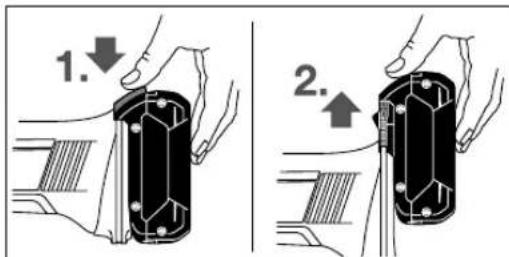
3a nBaxdahe Ha akymnatopHata 6atepyra (8) HATNCHTe OCBO6OxDabaaHb 6yTOH (9) Hn3BaTe AkyMnatopHata 6atepyra HanpeoT eEKeKTPoHHCTpymeHTa. PnTOBA He npnaarate cna.
Hndkatop 3a akymyataophata 6atepn(THnHa akymyataophata 6atepn GBA 18V...)(Bx.ΦnA)
Tpnte 3eneHH CBToHNOHa (27) noka3Bat CTeneHTHa 3ape-DeHOCT Ha akyMylatopHata 6atepna8. IpopaN cbOpaKeHn 3a CnpyHocn POBepkata Ha CTeneHTHa 3apeHeoCT e BB3MOKHa CAMO KOrAto ENEKTOPHCTPymeHTe B NOKOI.
3a da Bnnte cTeenHt ha 3apeHcOCT ha 6atePnTa, HATNC Hete 6yToHa (26).Toba MoKeJa Ce N3BbPsH n pRn N3BaEHa akymnatopHa 6atePn (8).
Cbetodnok Kanaunet
HnpeKbchato CBeTeHe 3 x 3eNeHo ≥ 2/3
Henpekbchato CBeTeHe 2x3eNo ≥ 1 / 3
CbeTOnoK KaanuTeT
HenpeKbchato CBeTeHe 1 x3eNeHo < 1/3
Miraa cBeTnHa 1 x3eNeHo pe3epBa
Ako CneHaTnCKaHe Ha 6yToHa (26) He CBETN HTOeINCBETOIOID, AkymynatopHata 6aTePN e NOBpeHAn Tp8BaJa 6bDe 3aMeHEna.
Yka3aHHe: HnIkaTOp 3a akymyIaTOpHata 6aTepeHr ce noKa3BaHa Notpe6bnteNcKm INHTepFeHc (5) (Bx. ,PiTope6bTeCKn INHTepFeHc (Bx. fHr. XD), CtpaHmua 323).
HdkaTop 3a akymyataophata 6atepna (TnHa akymyataopha 6atepna GBA 18V 6.3Ah, ProCORE 18V...) (Bx. qhr. B)
IeTte 3eneH CBETOHOHa HnHnKATOpa 3a akymnatopHaTa 6atepna (29) noka3Bat CTenENTa Ha 3apeHeocT. IopaA cnB6paXeHn 3a Chryphoc TnpOBepkata Ha CTenENTa Ha 3apeHeocTe Bb3MOxHc Camo KOrTo eNkTpOHnHCTpyMeHTbTe B NOKo.
3a da Bnnte cTe neta Ha 3apeHcct Ha 6atepna, HATNCHe 6yToHa (28).TOBa e Bb3MOxHO CbIoo H npn H3BaHe akyMnyatopa 6aTePra.
CbeTOnoN KanaaHTet
Henpekebchata3eneHa CBeTINHa5>80-100%
HenpeKbchata 3eneHa CBeTINHa 4 >60-≤80% X
HπpeKbchato CBeteHe 3 x 3eNeHo > 40 - ≤ 60%
HenpeKbchaTO CBeTeHe 2x3eNeHo>20-≤40%
HenpeKbchato CBeTeHe 1 x 3eNo >0 - ≤ 20%
Muraa CBeTnHa 1x3eNo 0%
Ako CneHaTnCKaHe Ha 6yToHa (28) He CBETN HTOeINH CBETOIOAD, AkymyNatOPHaTa 6atePnE e NOBpeHa n TpRbBa da 6bDe 3aMeHeHa.
YkaaHHe: HnKaTOp 3a akymyNaTOpHaTa 6aTePnCe noKa3Ba nHa Notpe6nteNcKn NHTepFeic (5) (Bx. ,Ntpe6nTeCKn INHTepFeic (Bx. FmR. XD), CpaHnca 323).
MOnTHpHaNe Ha 3aunTHo CbOpBXeHne
PpeHn da H3BpWbATE KAKBHTO n Da e DeHocTH no enEeKTPoHHCTpyMeNTa (Hap. TexHuecko 06cnyXbaHe, CMHa Ha pa6OTN HhCTpyMeNT H.T.H.), KOrato ro TpaHCnOpTnPaTe Hn CbXpaHbAte, DEMOHTPaHte akymnatopHata 6atePra. CbIeCTByBa ONaCHOCT OT Ha paHbAhe PnH 3aJeINCTBaHe HA NyCKOBn IpeKcbCaH NO HeBHImaHne.
Yka3aHHe: CneI cuynbAe Ha a6pa3nBEN dNCK nO BpeMe ha pa6oTa Hn npn NobpeKdane Ha npncnocobNeHnra 3a 3axBa7aHa eNEKTPOINHCTpyMeHTa Hn Ha npedna3HHKoKyxENEKTPOINHCTpyMeHTb Tp8Ba Da 6bde H3npaTeH 3a pemOH B oToPn3iPaH cepBn3 3a eNEKTPOINHCTpyMeHTn Ha Bosch, 3a adPecn Bk. pa3dEe"CepBn3Ha cnyXb N KOcyntaHn 3a npInIOKeHn".
IpeNa3eKoKyx3aWnHfoBaHe
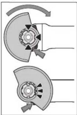
Noctabete npedna3nHKOxyx (11) Ha 3axBaunaTO CTbnaHO HA eNEKtpOHNCTpyMENTa Taka,ue KOnpauHTe rbpnsHa cBbNaHAT C KaHAnTE Ha CTbNATo. Pn TOBA HATNCHEt E 3aApBXte OCBO6OxxDaaHua NocT (1). PtInTHcTe npedna3nHKOxyx (11) KbM uHKata Ha eNEKtpOHNCTpyMEnTA, DOKATO 60rTa Ha npedna3nHO KOKyX DOpNe Do nHeuca Ha eNEKtpOHNCTpyMeHTA H3aBbPTe nped
Na3HHKoKxy,doKaTo yyeTe OTyETNBO npeupaKaBaHe.
PeynpaTeNo3nHTaHa npedna3HnKoJyX (11)cbo6pa3HO KOHKpETHnPe pOToHN yCNOBn.3a ceTnHaTNCHeTeOCBO6xDabuIINoCT(1)Harope n3aBbptTe npedna3HnKoJyX (11)B XeJenHATA No3Hn.
BnHaHn HAcTpoBaIte npEpa3HHKoKxY (11) taKa, ue n 3-Te YepBeHN rbp6uH na HOcBO6OxDabaunnaIOCT (1) da Bn3aT B npEbnDeHnte 3a cenTa OTbOp Ha npEpa3HHKOxyX (11).
HactpoIe npedna3nKaKoxy (11) taKa,ue da ce npedotbpaTBA nTeHTo Ha Hckpn no nocoka Ha onpeatopa.
PepnA3HHKoxyX11)Tp6BaJaMOxEJaCe3aBbptacmoKoratoOCBO60dabaunHtNoCT(1)eHaTCHAT!BnpTNBEHcnyaeyeneKTPOHNCTpyMeHTHe 6NBA B HNKAKBBcnyaJda6bJeON3BAH Tp6BaJa 6bJe N3npaTeH B cepBn3a peMOHT.
Yka3aHHe:KoInpaunTe Ib6nHa npPeIa3HnKoKyX (11) rapaHTpA,ye Ha eNkTPOINHCTpyMeHTa MoRt Da 6b- daMTMOHTpaHn CaMo NOxOJaUN ppeNa3Hn K0Kycn.
IpeDn3eH KoxyX 3a p3aHe
H3non3BaTe npn pnaHe cbc cBbP3aHa uKypKa BnHa-rn npedna3HHKoKyx 3a p3aHe (16).
Pn p3aHe B KAMbK BnHaHn OCHpyBaTe DoCTaTbHOMOuHa actnpauHOHa CHCTema.
PpeNa3HnT KOxy 3a p3aHe (16) ce MoHTnpa KaTo nped Na3HHKOxy 3a WnHPOBaHe (11).
Ppaxon3cmyKbau Koxyx 3a pR3aHe CBoeua WeHa
PpaxOn3CMyKBaunr KOxy 3a pR3aHe C BOeua WeyHa (30) ce MOHTnpa KaTO npEJa3HnR KOxy 3a WInHΦoBaHe (11).
CnomaratenaHa pbKoXbaTka
H3non3BaTe BaaHnEneKTPoHHCTpymeTcMoCMOHTnpaHa cNoMaTaENHpaBkoXBatKa (10).
3aBnHTe CnOMaraTeHnHaTa pkoXbTaKa (10) B 3aBNCmOCT OT HaunHa Ha pa6oTa BnCHo HnBnBO Ha peyKTopHaTa rnaBa.
B6ponornbua cnoMaratennpa bkoxbatka
Vibration
Bbponormbaaata cno
MaratEnHa pbkOxBaTKa Ha
MaIraBa IpeDaBAHnTe Ha
pbKaTa Bbpaunn OcnHy
PRABaNo-NeKaH No-cnHypHa pa60Ta.
B HnKaKb CnyaH He ce ONTBAHTe Da N3MeHrTe cNoMaTaTeHHaTa pbKOXBaTKa No KaKbBTo H Da 6HNO HaHH.
He n3no3BaHte cNoMaRaTeHHaTpa bKoXBaTKa, aKe e noBpeHa.
3aunra 3apbue
MOnThpaTte 3a pa6oTa C rMyen noIIOKeH nck (21) HnC yauKOBuHa TeHe Ha YETKa/INCKOBA YETKa/BetPnIOo6pa3e HnactHHaT Dnck BnHaTH 3aunrata 3a pbue (20).
3aKpenete 3auNTata 3a pbue (20)cbc cnoMarateHa pbkox-BaTka (10).
MoHTnpaHe Ha uHFOBaun HNCTpymENT
PpeHnHa H3BpWbATE KAKBHTO H da e DeHNOCT No ENEKTPoHnHCTpyMeHtA (HAp. TexHuecko 06cnyXBa- He, CMHa Ha pa6OTHnHmHCTpyMeHr T.H.), KORATO r TpaHCnOpTHpATE Hn CBxPAHBAte, DEMOHnPaIe AkyMnatopHata 6aTePN. CbueCTByBa ONaCHOCT OT Ha paHBAHe Ipi 3aJeCTBaHe HA NyCKOBn IpeKcbau No HEBHMaHHe.
He ndoKocBaTe, npedn da ca ce oxnaann. No BpeMe Ha pa6oTa dncKBote ce HarpBbAT cINHO.
NoCTe BAJa (19) BCnKn DetaHn, KOHTO e MOHTnpaTe.
Pn3aTgAHe HOCB6OxJaBaHe Ha HNCTpyMeHTte 3a WnHΦoBaHe HATNCHETe 6yToHa 3a 6nKpAne Ha Bana (3), 3a da 3aDbpxIne Bana HENoDBHXeH.
HaTnCKaIe 6yToHa 3a 6nKpHae Ha Bana cMo KOraTo To e B nOKo. B npOTHeB cnUay eNeKTponHcTpMyMeHTb MoKe da 6bJe NOpehen.
ДиСЗашнфован/рзан
BHHMaBaIte 3a pa3MepHte Ha HNCTpyMeHTte 3a WlnHFOBaHe.ДиAmeTbpbT Ha OTBopa Tpr6Ba Da e NOxOJn 3a NoemaUH PhaHe. He H3noJI3BaIte aadTepn nnppeyu npauu 3BeHa.
PnINON3BaHEToHaDnMaHTeHNpeXeUINNCKOBEBHMABaIteCTpeIKaTa3aNOCOKaHaBbPTHeHaDnCKaJaCbBNaDa C NOCOKaHa BbPTHe Ha ENEKTPOHNCPTpyMeHTa(BNXTeCTpeIKaTa3aNOCOKaHaBbPTHeBbpyEpyKTOHPaTgnaBa).
IocneIOBATEHOCCTHa MoHTaK e BnIMa Bbpx rpaHHaTa cTpaHua.
3a3akpenBaHe HaIINIOFOBbUHHaNCK/DnCKa 3a p3aHe H3- nON3BaTe 6bp3oo6TAAHraKa (14) 6e3npuHnHCTpyMeHTH.
N3noI3BaIte 6bP30o6TjXHa raiKa (14) cAmO 3a WnHPOBbUHN DnCKOB/EuCKOBe 3a pR3aHe DNCKOBc C ne6eHHa HAI-MHOrO Do 150 MM.
Bb3006T8XHATAraKa(14)MOxEJaCe H3non3Ba cMo 3a WnHΦOBvH NnPpeXeunDnCKOBe.
M3N03BaIe cAmO 6bp3oo6TJXHa raIka B 6e3yKOpHo cbctOHHne (14).
BHHMaBaIe npn 3aBnHTBaHeto 3a TOBa,HaINHcHaTa cTpaHa Ha 6bP30o6T8xHata RaKa (14)da He coyn KbM DnCKa.
3a 3aKpenBaHe Ha IINHFOBbYHH DnCKOBe /I nCKOBe 3a P3aHe H3NON3BaTe CaMo BKNIOueHaT B OOKMnNeKTOBkata 6bp30o8TrxHn RaKa (14).
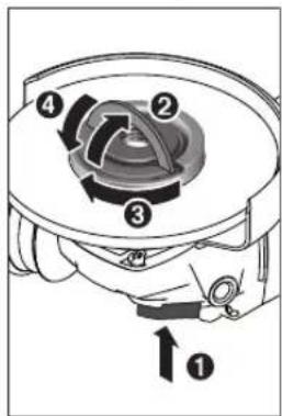
HaTnCHete 6byToHa 3aФHK CHPaHe Ha Bana(3),3aJa FHKcPate Bana 3a 7nnH OBaHe.3a Da 3aterHete 6bp 3OObTHKHata raKa (14), BnHete cKoBA tHa 6bp 3OObTHKHata raKa n 3aBbPTe CnHIO 6bp3OO- TkHATAra KaNo qacOB HNA.CBAnete cKoBA tA 3aFHKcPae Ha 6bp3OO- TkHATAraKa.3aTnArHe no Pb6a Ha DNCKa He e DOCTaTBHO.
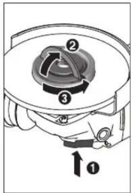
IpaBnHNo 3aterHaTata n HenoBpeDeHa 6bp30oobTnKa Ha raika (14) MoKe da ce pa3BHe Ha pbKa. 3a ueTa naOBnHHe TcKbata Ha 6bp30oobTnKaHa raKa n CnHNO 3aBbPteTe 6bp30oobTnKaHa raKa ObaTHo Ha acOBnHa. B NkakB cnyaH He ONHTBaHTe Da pa3BnBAte C hNCTpymENT, 3a ueTa HINON3BaHT KInOu C Dba OTBopa.
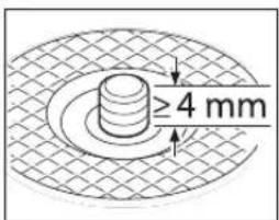
CneM OHTnpaHTo Ha cHTPOBaunnaPnAneu n DnCKa3a WnΦOBaH/Pr3aHeIbNnHaTa Ha CBO6OHaTape36a Ha Bana Tp86BaJa6bHe HAI-MANKo 4 MM.BHIMAbaTe paBtHnTnHCTpyMeHT 3a WnΦOBaH Da
e 3axBaHATdo6pe,3aJaHe ce OTdenn OT Bana nO Bpeme Ha BbPTHe.

OkoIc7bIaIOno 3a pa6obTHnIHNCTpyMeHHa CEHTPOBaUHnФNaHeu (12) e nocTaBeH npbcTeH OT N3KcyCTBeH MaTePnA (O-npbCTeH).Ako O-NpBCTeHbT HnncBa Hn e NobpeH, npeDn da NoI3BaTe CEHTPOBaUHnФNaHeu (12)
Tpa6Ba 3aIbIJIknteHNo da IocTaBnTe HOB O-npbCTeH.
CneMOnTHpaHToHaabpa3HNHHnck,npEnDa BKNIOHTe eneKTPoHHCTpyMeHTa,ceyBepTe,yeNcKbTeMOHTpAHnPaBHnHOHO MoKe Da CeBbPTN CBO
6oJHo. YBepTe Ce, Ye a6pa3nBHnT dNcK He oONHa do npEpa3HnKa KoxyX Hn Dpyr DaTaHn Ha eNKTponHHCTpymeHTa.
Betpnoo6pa3eH nIaTmHuat dNck
MoHTnpaTe 3a pa6oTH C BepHNo06pa3e HnnactHHaT DnCK BnHaH 3aunHtata 3a pbue (20).
TymennoJoxhenck
MoHTnpaTe 3a pa60TH cryMeHH noDnOKeH dNCK (21) BnHaH 3aunHtata 3a pbue (20).
IocneObaTeHOCTaHaMOHTaKeBnDImaBbpxyrpaHHaTaCTpaHua.
H36yTaTe rymeHnNoIIOKeH nCK (21) Bbpxu wHHnHeNa 3a WnfoBaHe (19).
ПиHTNCHeTe NtCTa Wkypka (22)ЗДрВО Вьрху ДОннATA CTpaHa Ha TymeHnI NOДNoXeH DnCK (21).
HabnTe Kpbrrata raKa (23) n 3aterheTc kIou c Dba OTOBpa.
aawkoBnHa TeNaeHa YeTa/IMcKoBA YeTa
MoHTHpaTte3a pa60TH CauKOBnHaTa TeneHa YetKa HIN DnCKOBaTa YETKa BnHar 3aunrtata 3a pbue (20).
IocneObaTeHOCTaHaMOHTaKeBnDImaBbpxyrpaHHaTaCTpaHua.
aawkoBnHata TeneHa YetKa/INCKOBaTa YeTKa Tp8BaJa MoKe Da Ce 3aBnHTBa DToTOKoBA BbPxy BaIa, Ye Da ce KICnpa Bkpar Ha pe36aHa Bana BbPxy PhaHeuHa Bana.3aTeRHeTe aWkoBnHaa TeHe HaYetKa/DnCKOBaTa YeTKa C BNKOB KIOU.
TbbpocnnaBEN qawKOBnDeHnck
Pon3BaHTo HaaWkoBnEHN DnCK Ce DoNyckCaMo B KOM6HHaUNC nOxOJU ppeNa3eKoKyX.
Pa3peeenn HnctpymEnTH 3a nnfoBaHe
Moxete da n3no3BaTE BCNUK NOCOeHN B HAcTOJIO pkoBOCTBO 3a EKCNIOAtaUNHCTpyMeHTN 3a UINFOBAHe. DOnyCTMHTE o60POTn [min] pecn. nepHΦepHa CKOPoCT Ha [m/s] HA n3No3BAHNTe HNCTpyMeHTN 3a UINFOBAHe TpR6Ba Da OTROBAPRT Ha-MaIKO Ha DAHHITE OT DOJIHATA TaBNIca. ETo 3aUO cna3BaIte DOnyCTMHTE o60POTn, pecn. nepHΦepHa CKOPoCT Ha eTNKeTa HA HNCTpyMeHTA 3a UINFOBAHe.
| Makc. [mm] [mm] | ||||
| D bd [min] | 1] [m/s] | |||
| 100 | 7 | 16 | 9000 | 80 |
| 115 | 7 | 22,2 | 9000 | 80 |
| 125 | 7 | 22,2 | 9000 | 80 |
| 150 | 7 | 22,2 | 7500 | 80 |
| 100 | - | - | 9000 | 80 |
| 115 | - | - | 9000 | 80 |
| 125 | - | - | 9000 | 80 |
MAKc.[mm][mm]
Dbdmin
150--750080

7530M14900045
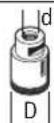
82-M14900080
BbpteneHa peykTopha rnaBa (GWS 18V-10 C)
Pepn Da H3BpWbATE KaKBrTO Ha a DeHocTH No eNekTPOHNCTpyMeHTA (HAnp. TexHuecko 06cnyXBa- He, CMHa Ha pa6OTHNA HnCTpyMeHT H.T.H.), KOrato ro TpaHCNOPTnPaTe Hn CbXpaHBAte, demOHnpaTe akymnatopHATA 6ateRn. CbueCTByBa ONaCHOCT OT Ha- paHBAhe npn 3aJeCTBaHe HA NyCKOBn PpeKbcBau NO HeBHMaHHe.
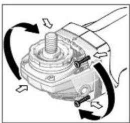
MoXe Ta 3aBbPte rnaBata Ha peyKTopa Ha cTbnKo OT NO 90^ .Taka npn CneuAHH pnpNoKeHn IycKOBH TpeKcbau MoKe da6bde 3aBbptn B yOboHaNo3nue, Hapn. ako Bne no-yo6Ho Da pa6oHTe C JRAba pbka.
Pa3BnTe HnBnHO 4-Te
BnHTa.BHmATEIHO HAKNoHEte peyKToPHaTgnaBaH6e3 Da cBaanTe OT Kopnyca H NoCTaBeTe B HOBaTa P03uJMa.
OTHOBO 3aTeHHeTc4-Te BnHTa.
CnCTema 3a npaxoynaBHe
PpaxoBe,OTdIaNcC npn 6pa6oTbaHeTo Ha MaTePnAnn KaTO CbDpKaaOnOBO 60N, HAKON BINODe DpbBecHnA, MHEpann H MetanMorat Da 6bDat ONaChn 3a 3dpabeto. KOHTaKbTdo KOKaTa NnBnWbHaTeO Ha TaKbA PpaxoBe Morat Da npedIN3BnKAT aneprHuN peakunn n/nn 3a6oJIraBaHnHa dInxATEHNTe TbTHUa Ha pa6oteu c eNeKTPOHNCTpyMeHa nn HAmpaNc Ce Habn30 nua.
OnpeeneHH npaxoBe, Hanp. OTeJnHte Ce npn 6pa6b0BaHe Ha 6yK nDb6, ce CHTAT 3a KaHcpeOReHH, OC6eHO B KOM6HaAua C XMMKaIIN 3a TpeTnPaHe Ha DbPBeCnHa (XPOMat, KOHcEpBaHTn HdP.).DOnycka Ce 6pa6bTaBHeTo Ha cbDbPkaAn a36ecT MaTePnAn Camo OT CbOTBeTHO 6byEHN KBaIIHfNpuHn Nla.
-OchrypBaIte Do6po IpoBETPBAHe Ha pa6oTHOTo MRCTO.
-ПpenopbyaCeH3noJI3BaHEnToHaIINxAteHnHaMaKa CФнтbpOtKlnaP2.
CnazBaHTe BAnHnTe BbB BaAuta cTpaHa 3aKoHOBn pa3nope6n, BAnHn npn o6pa6oTBaHe Ha CbOTBeTHnte MaTePna-
N368raBaiTe HATpynBaHe Ha npax Ha pa6oTHo MxCTo.
PpaxbT MoKe IeCHO Da ce ca moBb3IaMeHn.
Pa6ota c eIeKtpoHHcTpymeHTa
IyckaneBeknnoataa
NocTabraHe Ha akymnataopHata 6aTepe
BkapaTe 3apeHeHa akymyIaTOpHa 6aTepeHg (8) OTnpEi B OCHOBaHa eNEKToPHcTpymeHTa Iro npHTnCHeTe, DOKaTO 6bJe 3axBaHaTa 3dpBO.
BknIOuBaHe Hn3KnIOuBaHe
3a BkIIOUBaHe Ha eJKeTPOHnCTpyMeHTa IpeMeCTe TnyckoBn IpeKbCBaH (6) Happe.
3a3actonopbahe Ha IyckOBINIpeKbCBaC6)HaTnCHteIyckOBINIpeKbCBaC6)B IpeHnMy Kpa,IOKaTO yceTNTe IpeuPAkBAHe.
3aH3KIOUbaHe Ha eNEKTPoONHCtpyMeHTA OTNyCte NyCKO BnI PneKbCBauch6pecn. ako e 3actOnopeH, KpaTKBpemEH HO HATNCHEH NOYNCHETe NyCKOBn IpeKcbBauch6
Pepnnon3BaHe npOBepBaaTe wHnFOBaunTe HCTpymENT. WnHFOBAaHr HNcTpymENT Tp8Ba Da eMOHTpan 6e3yKOpHo n da MoKe da Ce Bbptn CBO6oHNo. OCTABnTE 3a npo6a HNcTpymEnTa da Ce Bbptn BnpDJIxKeHne Ha hainMAnko 1 MmHyTa. He n3non3BaTe NOBpeHn, 6heu nn HNbPnpauw HnHFOBaun
HnCTpyMeHTN. TObpeEnuIINFOBaUN HnCTpyMeHTN MoRat Da ce pa3pyuAT N da InpEIN3BnKAT HapaHbAHNA.
N3KIIuOBAhe npn o6paTeH oTKaT

PnBHe3aHEn OTKaHa eNekTPOHNCTpyMeHa, HAp.6boknpaHne NO BpeMe Ha p3aHe, NpaBaHTo Ha TOK KbM eNekTPOBNrAteNaCe npeKbCBAOTeNekTPOHn PpeDna3Ha CnCTema.
Hnkora He m3non3BaTe pexeun dnckoBe 3a rpy6o nnfoBaHe.
HaJIOpeyntn npIpy6oIINFOBaHe ce noCTHnat npi HAKIOH HA nCKaO 30°do 40. PpNDBNKBAte enKTponHCTpymEtA CymepeHO pNTHCKaHe HApEe HHaazd.Ta Ka O6pa60TbAHnJeTaH He CE HaPRABa IpeKaaneHo, He Ce 6pa3yBat UBeTHn IBuHn H6pa3dn.
Betpno06pa3eHnactnueatdck
C Bepnnoo6pa3HHI INaCTHcHAT Dnckder (npHaJNeKHOCT) MoXeTe Da o6pa6oTBaTe N 3NbKHAn NOBbpXHOCTN nPo-
Betnnoo6pa3HNTe nactHuaTINCKOBHe HMaT 3NaHTeHNOIbIgA EKcIIOaTaUHOHa IPOdbJXHTeHOCT, IIO-HNcKO HNo BA WUM NIO-HNCKTNMeMepaTyH NaIINΦOBAHe OT ObnuayHHTe INCKOBe 3a WlnΦOBAHe.
PraaHaMaTAn
MAnon3BaTe npn pR3aHe CbC CBp3aHa Wkypka BnHa- rH npedna3HH KOKyX 3a pR3aHe (16).
Pa6oTe npn p3aHc cymeHo, c6o6pa3eHo c o6pa6oTaBnHa MaepnA nOdaBaHe. He ynpaKnaBaeTHe HATCK BbpxNcKa, He pexete IIO bIbI N He rO KNaTe.
He cnnpaite DnHexeIte Ce no Hnepe npexu nDnCKoBe Upe3 ctpauHua KOHTpa.
EnkponHcPymentbT TpaBa da ce BODn BNHnI nOanBaBe B opaTa H NOcoKa. B npoTHBEN Cnyaun Cb- ictByBa ONaCHOCT ToJ da 6bJe NxHBpIe HekOHtpOnHypeMoT cpe3a.
Pn pr3ahe n npoФHn H ueTnpbBbHn Tp6bHn Ha- dObe n3noJ3BaHTeMHn
MaJIHOTo HAppeuHo ceueHne.
P3aHeHaKaMbK(BX.ΦnR.C)
Pn p3ahe B kambk BnHaH nOchpybaTe DOCTaTbH OMOuHa actnpauoHn CHCTema.
Pa6oTeC npOTNBONpaxObaMaCKa.
Donycka ce h3noJ3BaHeto Ha HHEBMaTHHHHNCtpyMeHT cmo 3a cyxo p3aHe/UnnfoBaHe.
Pn p3aHe Ha KaMeHH MaTepHaH e Hau-Dobpe da n3non3BaTe dAmAHTepeKc
PnH3non3BaHeToHa npaxoH3cMykBaU KQxuy 3a p3aHe C B0e7a UeHa (30) npaxocMcyKaUkTa Tp6Ba Da e pa3pe- uHa 3a HcMcyKBaHe Ha KaMeHHn npax. Bosch npedna nOdoxOAn npaxocMcyKaKN.
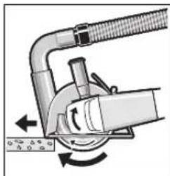
Bknoute enektpoHnCTpyMeHTa HIO NOCTABe TbpxyTeaHa CnpedHata aact HaBoDaeuata WeyHa. PnIDBnKBaIte enektpoHnCTpyMeTcCaMpeHo NODaBAHe, cbo6pa3eH c o6pabOTBAHN MATEPHA.
Pn p3aHe Ha oO6eHo TBbpN MaTeHn, HAp.
6ETOH C BNCOKO CbIbPkaHHe NaKaBJI,ДиMaHTeHrTДИСКМоже Дпррee Идс се NOВpeiN.ИckpTe OKONOДиMaHTeHrДИСК CaЯВEN ПИЗнak 3a TOBa.
BTo3n Cnyaun npekbchete p3aHeto n octaBeTe nnamHeTHN Hnck Ha npaeH XoD npn MaKcMaHn HOBOPTu 3a KpatKO, 3a da ce Oxna.
3HaunTeHnHaMaIeHa IpnO3BODInTeHIOCT N O6pa3yBaHTo HA BeHeU OT NCKPN NO DnCKa Ca Yka3aHnHa 3a TaTbNBAHe Ha DaMaHAnTEHnDnCK. MoKTe Da rO HatoHTuNE Upe3 KpAtonCpe3oBe B abpa3nBEH MaTePnA, HApN. CnNkATha TyXNa.
Yka3aHnHa 3a CtaTHKaTa
Cpe3oBeB Hocseu CteHn Ca o6eKHa cTaNapt DIN 1053
act 1nn CneunpnuHn 3a cTpaHata pa3npoe6b. Te3n
npedncaHn Tp6Ba Da ce cna3Bat HepeMeHo. IpeHn
haaIATO Ha pa6Ota npNBneye OTOBOpHn cTaTHk, apXHTE KOMNeTeHTHn pbKOBoDInTe o6eK 3a KOHCyNTa-
zua.
Yka3aHHa 3a ONHMaHNo 6opabHe c akymnatoPnata 6aTePn
Pepnna3BaIteakymyIaTOpHata6aTePnHaOTBnAraNBOda.
CbxpahraBaIte akymnatopnata 6aTepeRn caMoB TemnpaTyPhN dHaana3oH ot-20 ^ C do 50^ .Hanp. He octabTHe akymnatopnata 6aTepeRn ppe3 IaTOTO B aBTOMObH na CbHcE.
IepnoHnO NOCTBaTe BEHTNaUHOHHNe O TBOpHa akyMnyatopnata 6aTePnca MeKa uCTa H cyxa Yetka.
CbueCTBeHO CbKpATEHO BpeMe 3a pa6oTa cne3apeKdahe nok3Ba, ye akymnatoPnHata 6atePnE n3xa6eHa H Tp8Ba da 6bde 3aMeHeHa.
CnBaBte yKa3aHnTa 3a 6paKyBaHe.
326 | MaKeJIoHcKn
PoaBpKaHe n cepBu3
PoaBpKaHe n nouchTaBe
PpeHn Da N3BbPwBaTe KaKBHTO Ha e DeHIOCTNo eneKTPoHHCTpyMeHtA (HAnp. TexHuecko 06cnyXba- He, CMHa Ha pa6OTHm HnCTpyMeHT H.),KORATO r TpaHCNOpTHpATE Hn CbXpaHBAte,DemOHnpaIte akymnatopHata 6ateRn.CbUcETByBa ONaCHOCT OHa paHBAHe npH 3aJeCTBaHe Ha NyCKOBn PpeKcbCau No HEBHMaHHe.
3a da pa6oHTHe KaueCTBeHO 6e3onacHo, noDbPkaTe eneKtpOHnCtpymeHa N BEHTNaUHnHnTe MyOTBOPHnCTH.
CbxpaaHbAteNceOTHacraTe KbMDoITbHHTeHHTePnHaDnHexKHOrTnPnKnBO.
KInHeTcKa CnyX6a H KOHCytTaunr OTHOCHO ynotpe6ata
CepBn3bT 足OTROBOPH HbBnPocHTe Bn OTHOcHO peMOHTN HnoDpBjKkHa 3aKaynHeHr OBa npOdyKT, KaTO HOTOC HOpeEPBHNactH. POKOMNOHETHNueptExn INHΦOpMa- 3a peEPBHNte yactH 足OTKpIeHr Ha: www.bosch- pt.com
EkntnoKocnytauaOnTOHcOHOynotpe6ataHaBoschue Bn NOMORHe cyIOBOJCTBHe npN BbnpoCH3a HauHTe npOdykTN TexHNTe akcecoapn.
MOnn, npn Bbnpocn n npn nopbyBaHe na pe3epBnH acTn BnHaHn NocOyBaIe 10-ncppeHH KaTALoJH HOpE, n3nnCah Ha TaBeKkata Ha ypeA.
Былария
Robert Bosch SRL
Service scule electric
Strada Horia Macelariu Nr. 30-34, sector 1
013937 Bucuresti, Romania
Ten.: +359(0)700 13667 (Блгарский)
_aKc: + 40212331313
Email: BoschServiceCenterBG@ro.bosch.com
www.bosch-pt.com/bg/bg/
TpaHcnpOpTnpaH
BkHoueHIne B OKOMnNEKTOBkata HINTHeBO-NOHHaKMyIyTapOHn 6atePHn Ca B OxbBaTa Ha N3NCKBaHNrA Ha HOpMaTHBHnTe DOKyMeHTN, Kacaeeu npOdyKTc NOBHHeoNACHOCT. AkymyNatOPHTHe 6atePHn MoRat da 6bDat TpaHCnOpTNpaHn OT Notpe6nteHa Ny6nHm MeCt 6eDOnbHnTeHnPa3peWnteHn.
Pn TpAHCNOpTnPaHe O TpeH CTpaHH (Hanp. npBb3dyuWe TpAHCNOpTnnn NON3BaHe Ha Kypnepcn yCnyr) HMa Cneun AINH 3nCKBaHH KbM ONaKOBaHE To 06o3HaabaHETo HM. 3a ceta PnnpnoTROBkata Ha NaekTpHaTe Ce KOChytnpaIe C eKcNEPT B cbOTBeTHata Obact.
H3npaauIte akymnatopn 6atepn cmo aKO KOPnycBt Hne e NOBpehen. 13oJIpaIte OTKpHTN KOHTKN KEmn C nePAnu NeHTN ONAKOBaTe akymnatopn 6atepn taka,ue da He MOrTa ce N3MeCTBaT B ONaKOBkata CN. MoJra
CnBaBTe CbIoo IOnbHHTeHH HaIOHaHN npeDncaHH.
Бракувае

EnktonHcPymeHTne,akymnatoPnHte6aTepnnnoBnHnTeHHne npncocobnna TpaDa 6bDat npedaBaan 3a onoN3OTBpA
BaHe Ha cbIbPkaIHTe Ce TBx CypOBHnH.

He 3XbpyIe enektpoHHcTpymEnn aymynatopnn nn no6nKHOBeH 6aTePN npn 6TOBNTO nadu
Cama 3a ctpaanOT EC:
CbINaCHO eBpOeNcKa dIpeKTHBa 2012/19/EC eneKtpoypeNTe, KOHO He MOrAT da CE nON3Ba TNOBEue, a CbINaCHO eBpOeNcKa dIpeKTHBa 2006/66/EO nobpeHn HnH3xa-6eHNoBHOeHNn AkyMynatopn HsATEPHN Tpa6Ba Da ce CbHpatn PpeDa 3a OOn3OTBOPBAHe Ha CbDpXaHTe Ce BTRxCypOBHH.
AkymynaTOPH HnO6NHOBeHN 6aTePHN:
JIHTHEBO-NOHHN:
Mon, cna3baTeyka3aHnTaBpa3deJa TpaHCnoptnpaHe (Bx. TpaHCnoptnpaHe", CtpaHnca 326).
MaKeDoHcKn
6e36eHocnHaNoMeHN
OnuTn npdeynpeyBaHa 3a 6e36eHocT ha enEKeTpHuAnaTH

IPEyIeYBA IpoHTajTe HcTHeHaNoMeHH HeE yNaTcBa 3a 6e6dHocr. PpeWKITE
HaCTaHaTH KAKO pe3yNTaOD HEnpHnDpKByBaHe Do 6e3bEHNCHHTe HANOMEH N yNaTcTBa MOKe Ja npedN3BnKaat EneKtpuH eYap, NoKap N/Inn TeUKN NOBpeN.
3auybajte H6e36eHocnHTe npedeynpeyba H ynatCTBa 3a KOpHebe H3a BOHNHa.
PnoHOT,eneKTPnueH anat"BO 6e36eHOCHTpeDynpEyaBa ce OHeCyBa H eEeKTPnHn anapatn wTO KOpHCTAT cTpyja (ka6enckn) nn anapatn wTO KopHcTa6aTeHN (akymnatopcn).
Be36eHnoct Ha pa6oTHnOt npocstop
Pa6oTHHOT npocTOp oPjxByajte ro uHCTn no6po OCBtien. IpeNoHN Nm TEmHN IpocToPN MoKe da DoBeaTdo HecepKa.
He paBoTe co eNEKtpuHHTe anaTH Bo EKcNnO3HBa OKoJHbA, kako Ha npHMep, BO npHCycTbO Ha 3anaHbH TeuHOCTH, rAcOBn HnnpaHHa. ENEKtpuHHTe anaTH
C03daabaT NCKPKNKUTo MOKe Da ja 3aanaT npaunHata HnI racoBITE.
DpKTe Hn deaTa H npCyTHHe nOdaNeky DoeKa pa6oHTHe co eneKtpueH anat. HeBHHMaHHeTo MOKe da npEIN3BnKa Da n3ry6He ToKHTpOna.
EJektpnha 6e36eHnoct
PnKnyokot Ha eKtpnHOT aHa Mopa da odroBapa Ha npKnyuHuaTa. HNKoraH He ro MeHyBaJte npKnyokot. He KopHCTHe npKnyuHn adantepn co 3a3emjeHnte eKtpnHn anath. Hen3MeHHTe npKnyUOuH n COOBETHne npKnyuHnTo HAmayBaat p3NkOT oD cTpyeH yap.
H36erHyBaJTe TeneCen KOHTAKT CO 3a3emjeHH NOBpuHH, KAKo Ha npHMep,ueBKN, paNJatOpH, MeTANHH NAnu NAnHnHn. NoCTOHrOeMeH pN3NK Od CTpyEH yAp aKO BaWeto TeNo e 3a3emJeHO.
He n3noxybajte enektpnHHTe ana H aOxk nnBnaXHH ycnobn.AKO Bne3e BOda BO enektpnHNT aanTKe ce 3rolemn p3nKOT od cTpyen ynap.
He noctanybaije hecooBethe co KaBenot. HnKoraw He ro KOpHCTe KaBenOT 3a HocBe, BneYebe nn HcknyBaBe od ctpyJa ha enekTPuHHOT anat. KaBenot cyBaTe ro nOanEky od orAh, MaCNO, OCTpn HBnH Nn NOBnKHN DenOBn. OHTeEHn HnN 3aJINeTKAHn KaBn r 3rOleMyBaAT Pn3IKOT OD cTpyeh Ydap.
Pnpa6oTa co enektpuueh anat Ha oTbopeHo, KopHCTe npOOnxhen Ka6en cooBeten 3a HAdBopeHa yonTe6a. KopHCTeHTo Ha Ka6en COoBETe 3a HAdBopeHa ynoTe6a ro HamanyBa pN3NKOT OCTpyeh Yap.
Ako Mopa da pa6oHTe co eeneKtpnueH anat Ha BnaXkHO MeTo, KopHeTe 3aunTHe nped 3a nDhepeHnJnHa cTyja (RCD). KopHeTeHo Ha RCD ro HamaIyBa pNikOt on cTpyeH ynap.
HnUHa 6e36eHnoCT
BnTe BnMATEHn, BHIMAbaje KaKo pa6OHTe npa60Te pa3ymHO co eKeTPhueH anat. He KOpHCTe eKeTPhueH anat aKO cTe yMOPHN HNOd DeJcTBo HA DpOH, ANKOXON HN NekOBH. EeH MOMENT Ha HeBHnMaHHe DoJeKa pa6OHTe co eKeTPhuHte anAT MoKe Da DOBeDe Do cepno3Ha NHy H NOBpeJa.
Kophtete NnHa 3aHTTHa onpema.Cekoraaw Hocete 3aHTTAta 3oH.N.3aHTHTAata ONpeMa, Kako Ha np.. Macka 3a npab,6e3eHnOCHN YeBn KO He CE IIN3raat, WJEM NH 3aHTTA 3a yuN, KO CE KOpCTa 3a COOBETHN YCIOB,Ke IOBeJa Tdo HAmAlyBaIbe Ha IINHn NOBpei.
CnpueTe HeHamepho aKTHBnpaBe. PpOBepeTe daHn pKeHHyBaUOT e NCKnyeH npEa Da ro BKnyHTe BO cTpyJa H/nn Co CETOT Ha BatePhn, npEa Da Ro 3eMeTe HnH HocHTe anatot. HocHe Ha eneKTPnuHtete aIaN co npCTOT n03uOnHpaH na pKeHHyBaUTn HnBkLyHuBaBe BO cTpyJa Ha eneKTPnuHtete aIaN uJluTo pKeHHyBaUOT e BKlyueH, MOKE da npEniSbNka HecpeKa.
OctpaHETe KaOB 6nno Kny3 apeyHpaHe nnn φpaHcyckn Kny nped Da ro BknyHTe eNEKTPuHHOT anat.ΦpaHcyckn Kny nn Kny npHKayeh 3a potpaKnot den Ha eNEKTPuHHOT anat Moke da DOBeDe do NnHa NoBpda.
He nI pneukopybaje orpaHnuyBaHata. Noctojano odpxybaje cooBethe na noox6a h paMhoteka.OBa OBO3MOxYBa NOO6pa KOHTpOna Ha eJeKTPnHNOt anat BO HENpeBnINIBn CHTyaUN.
06neyece cooDBetHo. He hocete umpoka 6nkeHa nakht. Kocata,anHTa n pakabHnte Tpe6a da 6ndat noJaNEky oNIOBHXHNTeJeNOBH. HpOKATA 6nke, hAKHTOT Hn DOnrTa KOCA MoKe Da ce 3aKaayat 3a NOBHXHNTe JeNOBH.
Ako ce Kopnctat noBp3aHnypeHn 3a Baedebe npaunHa n Co6npaBe npEmTe, npoBepeTe daHn ce npaBnHO NOBp3aHn KOpHeTn. Co6npaHeto npaHnMoKe Da Hn HaMaJIOn aNCHOTe npedn3BnKaHn OJ Hea.
YnOtpe6a H cyBaHbe Ha eNekTpHnHTe anATn
He ro npeontobapybaje eneKtpnHnot anat. Kophtete cooDBeteh eneKtpnuH anat 3a Hamehata. Co cooDBETHNOt eneKtpnuH anat noo6po, no6e36edno n no6p30Ke ja u3BpuHte paOta 3a koja e Hamehet.
He Kopnctete enektpuueh anat ako he moxete da ro BknyuHTe HcknyuHTe co nomou Ha npkeHHyBaOT. Ceko jeneKTPuueh anat kojUTo He moKe da ce KOHTpOJInpa co npkeHHyBaOT e onaceH mOpa da ce nonpaBn.
HcknyeTe ro enektpnHnot anat od ctpya n/nnn ceTOn Ha 6atepHHo enektpnHnot anat, nped da npaBnTE HeKAKBN pnpnaRoDyBaHa, MeHyBaTe DOnONHTENHa ONPema Hnro CKNaHpaTe enektpnHnot anat. Co OBE npeBeHTNBH 6e36eHocHN MepKn CE HAmanyBa pN3NKOT OD CNYaJHO BKNyUyBaHe Ha enektpnHnot anat.
UybaJTe Hn EneKtpnHHTe anATH NOdaneky Odoat Ha Deua Hn He Do3BonyBaJte Ncata KOHpe pakybanco eNeKTPnHHTo anAT Hn HE CE 3aNo3HaEH CO OBAynATCTBO Da paBoTat Co nCTHot. EneKtpnHHTe aIaTH ce onacHN BO paQeTe Ha Heo6yuHKnopncnHn.
OpjyBaHe Ha eneKtpnHn anaTH. PpOBepTe ro npamHyBaBeTo Hn nPiuBpCTyBaHe Ha NOBHXHTe DeOBn, CnoJOT Ha DenOBHe N cHTe DpyrN ycNOB uTO MoKe HeaTHBHO Da BnJaT BP3 cyHKUHOHPaBeTo Ha eneKtpnHnO anat. Ako e oWTeH, Ondecete ro eneKtpHHoanat HA nonpaBkna ppeDa ro KOPHCHTe.Mhory hecpeKe ce npedn3BnKaHN 3apadn HecooDBeTHO ODPXyBaHe Ha MOKHTE aNaTH.
OctpeH uHCTeTn anaHTte 3a ceHe. CooBcHo ODPKByBaHITe HbUHa aIaHTte 3a ceHe bOMaIKy ce BNTkaat n IIOeCHO Ce KOHTPOINpaT.
EeKtpnHnot anat, dononHntenHata onpema, denOBHTe nDp., KOpCTeTe rBO coRnacHOCT CO OBA ynatCTBO, BHmAbajte Ha pa6oTHTE ycNobn H pa6otata Koja ja Bpwnte. KopCTeHbeto Ha
328|MaKeDoHcKn
eneKTPnHNOIaT3aIpyrHaMeHNMOKeJaIOBeDeIO ONaCHN CNTyaUIN.
Ynortpe6aHyBaBeHa6aTePncKnaT
Nonhe ja 6aTePnJa cAmo Co nonHa HabeEn O npOn3BODHTenOT. NonHau KoJTo e COOdBteH 3a eEHN TnCet Ha 6aTePNMOKe Da npedn3BnKa OnaCHOCT O nOKap aKOce KOpNCt 3a dpyr CET Ha 6aTePN.
EneKtpnHHTe anaTH KopHeTe Tn cmo Co CneunjAnHO HameHen CTOBn Ha 6atePHN. KopHeTeHo Ha npyHn CETOBn Ha 6atePN MoKe Da npeu3BnKa ONaCHOt OD NOBpeDa NnnoKap.
Kora He ro KopnCTnte cetot Ha 6atepn, yybaje ro noaneky od npyrn Meaannn npedmetn, KaKO ha np., cnojybanKn, MOHETN, KnyeBn, Wajkn, 3abptkn Hnnpynomaih metaHn npmedtn uTo moKe da npdN3Bkaat cnoj od eHDo npYr H3BOp. KpaTOK cnoj Ha 6atepcknte n3bOpn MoKe da npedn3BnKa n3ropeHHn Hnnokap.
PnHnpeBnEHN OKONHOCT, TeuHocTa MoKe da HcTeue OJ Batepjuata; N36BerHyBaJte KOtAKT. PnCnyaen Donnp, N3MJuTe ce co Mna3 Boda. Ako TeuHocTa BnEe BOOnTE, NobapajTe DOnONHTenHa MeNCHCKa NOMOW. TeuHoc THeueHa OJ Batepjuata MOKe da npEn3BnKa npntaunJa nnN 3rOpeHnI.
CepBnchpahe
EneKtpnHnot anat cepBncpajte ro kaj KBaHnΦHKyBaHO nue Koe KopHcTc moHeHTuHN pe3epBHN denOBn. Co Oba ce OBO3MOxYBa 6e36eHOn oDpKyBaHe ha eneKtpnHnot anat.
Be36eHocn HAnomeHH 3a aOrHn6pycnKn
Be36eHocn npEynpeyBaHa 3a 6pycebe, mHrpnahe, XnHauHOyTeKaHe n a6pa3nBHO ceYebe
Oboj eeneKtpnueH anate Hamehen da yHKnoHnpa KaKa oanat 3a 6pycebe, mHrpnahe, xHuayo yeKaBe HnCepeHe. Ipooyntaje r nCte 6e6ednCH npdynpdyBaHa, hNyctpaunu H cneuHkauu npnoxehco OBOJ eeneKtpnueH anat. PeeKHTe HactaHaTn Kako peynta Ha HENpIpyXyBaHe do CNTe HNCTpyKUnn pInNOxehn IOIOly MoKe Da ppeIN3BnKaat CTpyen Ydap, NOkap N/INn TeUKN nobpeH.
Onepaunite kako ha np. nonnpahe He ce npenopayba da ce Bpwat co ojoj enektpuhen anat. Oepaunite 3a kon He e Hamehet enektpuHOT aIaT MOKe da npedn3BnKaat onachOCT nHnHa nobpeda.
He Kopncte DoonHntenHa onpema Koja He cneunjanno H3ajnnpaHa H e npenopayana od npoun3bOHTENOT Ha anatot. Camo 3atoa tto DOnONHtEnHata ONpema Moke Ja ce BrpaHn BO BaWnOt eNEKtpueH anat, He 3nau DeKa Moke Ja ce 06e36eHn 6e36eHn paBotehe.
YbpeHata 6p3nHa Ha dononHHTenHata onpema Mopa da 6nHe hajmanky ednakba Ha mKcHMaHnHata 6p3Ha O3haeHa H eNEkTPuHnot anat. DononHteJHata onpema koja pabotn no6p3o od YbpeHata 6p3Ha Moke da ekcnIOnpa n da ce pacnpcka Hacekae.
HaBOpewHHotnJametapNde6eHHaHaBaWata TaONOHHTENHaONPemaMopaDa6HeBOpaMKHTe Ha KNaCATAHaBaHnoteneKTPuehAnat.0NONHHTENHa ONPemaCoHEcooDBeTHaBEHnHHeMOKeCOOBeTHO DaCe3aHTTN KOHTpOJInpa.
HaboJOT 3a MOHTnpaBe Ha donONHnTeHHata onPema Mopa Da ODRObapa HA OCOBHATA 3a MOHTnpaBe Ha 6pyCNkata.3a donONHnTeHHoNpema Koja ce MOHTnpa Co nppa6hnta, HacaedHnot OTbOp Mopa Da ODRObapa Ha dJaMetapot Ha cnojHata nppa6hnta. DOnONHnTeHHata ONPema Koja He e COODBeTHa Ha XapDbepot Ha eNEKTPnHnOT anat He MoKe Da ODPKyBa pAMHOteKa, 3apaNi PpeKymepHnTe BnBpaunu NMOke Da npeDn3BnKa rSybeHe Ha KOHTpOla.
He KophcTe OwTeHa DononHHTenHa onPema. Ipey ynoTpe6a npOBepe Ja dononHHTenHa ta onPema, KaKa Ho np., 6bpa3nBnTE DnCKOBn 3a HBPKN CTpyrotHH, 3aWTTHata NDnora 3a OTBOpN, CtpyKeBe NnnpTepeAo abEbe, XnuaHata yeTKa 3a OnabaeHH Nn NyKHATN XnU. Ako eneKTPnuHOT anat nnn DoONHHTenHa onPema naHne, npOBepe TaHn e OwTeHa Nn HCTanHpajte HeoWtete HaonHHTenHa onPema. IIO npOBepkata HnCTaHpaBeTo Ha DononHHTenHaTa onPema, Bne H nyfeto BO 6nHnHa Nomctete Ce nOdaIeKy od NobpHnHa T ha oTnpAchta ONPema, H BknyeTe ro eneKTPnuHOT anat Ha MaKcHmHa 6p3nHa 6e3 ontobapBaBe edHa MInyTa. OwTeTeHata DOnonHHTenHa onPema Bo06uHaeho ce pacinyBa Bo TeKOT Ha OBOJ Tect nepNOi.
Hocete NnHa 3aHTTHa onpema.Bo 3abhchoct od npmehata, KopncTe TE 3a HNKe 6e6bHocHH nnn 3aHTTHn ouHna.Kako wto e cooDbetHO,Hocete MACKa 3aHTTHa o nnpaunHa, 3THTHn3a ywn,pakabnnpa60THnka npectnKa,KoajTo rH 3anHpma Mante a6pa3HBn npauhbaa ndenot wto ro
06pa6otybaTe.3aHTtata 3a OH Mopa DA OBO3MOKHN CnpeyBaBe Ha OCTatoOnI WTo ce pacnpckyBaAT npn pa6oTeHbTo.Mackata nPOTNB nPAB INn pecnnapoTmOPa Da Hn FInTPnPA YecTHNkHe WTo ce reHepnPaat npn pa6oTeHbTo.DonrOtpajHa N3IOKeHocT Ha INTHENBHa 6yaba MoKe da IOBede Do rSybe Ha cnYxOT.
NyfeTO BO BAa6 6nH3Ha Tpe6a Da 6nDat OdaaneuHOn pa60THOT IpocTOp.Cekoj wTo BneryBa BO pa60THOT IpocTOp MopA da HOCH NnUHa 3aHTHTOn onPema.PapuHa oD denot wTo ro o6pa60TyBate HnIpaCnnaHdoONIHHTeHa ONPema MoKe Da EKcnIOnpa HpacnPcKa n da npEIN3BnKa NOBpeHa HADBOP od HenocpeHnata pa60THa NOBpHHa.
DpxkTe ro enektpnHnOanat 3a H0nnpaHATA NOBpuHHa DnEka CEyTe CO DOnONHTENHa T Onpema, 3a Da He DojBe BO KOHTAK Co CKPHeHa XuA. Ako Onpemata 3a Ceuehe Bo JOpNp Co KUa NOD HAIOH,MOKe Da Hn HnIOXm MetaIHNTE DeNOBHa
eneKtpnHnOtnanat,noHnHO nonepaTOpOTMOKe da do6ne cTpyeH ydp.
He ro octabajte enektpnHnot anat dony dokeka DononHttenHaT aOnpema He 3anpe cenocho. PotpaKaT aOnpMa moKe da ja 3a4aTH NOBpuHHata n Da ro NobIeue enektpnHnot anat HADBOP od BaHa KOHTpOJa.
He ro BknyuBajte eneKtpnHHot anatdoKea ro DpKHTe CBPTEN KOH Bac.Cnyaeh KOHTaKT co potpaKa DOONHITEnHa ONPema MOKe da ja 3aKaun BaWata ObNeKa,co NobNeKyBaHe HOnOINHTenHaTaNpema KOH BaWTeTo TENO.
PeOBHO uHCTeTe rB03dyuHHTe BeHTnHa eNEKTPHHOT anat. BeHTnAtoPOt Ha MToPOT NOBLeKyBa IpaB BO KyKnIteTo, a npTepeHaTAt akymnauiJa Ha MeTaIe NpAB MoKe Da npEdu3BnKa onaCHOCT OJ eNEKTPuHEn ydap.
He pa6oTeTe co eNeKtpnHNot anat Bo 6n3Ha Ha 3anaHBMaTepnjann. NcKpHTe MoXaT da Tn 3ananaT OBHe MaTepnjann.
He KopncTeTe DononHnTeHa onpema 3a Koja ce noTpe6Hn TeuH naDyBaun. KopncTeHeTo B0da Hnnpyn TeuH pa3naDyBaun MoKe da DoBeJe DO cmpt Hn n CtpyeH yap.
O6nBaHe HIOBpAHN INpeDynpDeYBaHa
O6nBaHe e HeaJejHa peakuJa Ha npKneTHe Hn3aKaueH pOnpaKn Dnck, Notnpen Dnck, Yetka HnDpya DononHtEnHa onpema. PnKNeTuBaHbTo n3aKauyBaBeTo npedn3BnuBa 6p30 Mahebpnpabe Ha potaOnHa TOnonHtEnHa onpeMa, KoE od pyra CtpaHa, npedn3BnuBa npncnHo HacoyBaBe Ha HEkOHpONpaHHOT eneKtpuH e anat Bo cnpotHBnepnBeC oD pOnpaBeto HA onpemata BO TochKA tHa HabanyBaBe. Ha npmep, ako abpaznBuHd nck e 3akaueH npiKneTHe O denot wTo o6paBotate, octpuaHa dNcKOT Koja BneryBa BO npKneTeHATA ToCu Ka Moke da ce 3apne BO NobpwnHata Ha MATEpNJanot nckKOT da ce Nomctn HnocNoBodn. NcKOT moke da cKOKHe nOnd6he O onePAPOT, BO 3ABNCHOCT O hACokata Ha dBHXebe Ha NcKOT BO ToCHa HpKneTuBaHb. AbpazNBHTe NDCOBn, HTO TAKA, MOKE da Ce ICKPwAT NOd OBne ycNOB. O6nbABoTe O pe3yTTat Ha NorpeuHa ynotpeBa n/nn HecooDBTHn ONepaTHBn NoCTAnKn HnycOBn mOKe Da ce n6berHe co ppe3MaBe HcooDBETHe TpeBEHTNBm MEPKN pInIOKeHN IOOly.
LbpcTo dpKeHe ha eneKtpHnHOT anat H no3nOHHpaBe Ha BaWeTo Teno n paka 3a da ce OBO3MOxN OTnOp Ha CNHTe Ha O6BHaBe. Cekorau KOHNCTe NOMOHa paKa, DOKONky HMa, 3a MAKcHMAnHa KONTpOna Ha O6NBaBeTo HnCnTaHa BPTeH npn BknyBaBe. OepaTopoT MoKe Da rH KOHTPOInpA peakunite Ha CNnata Ha BPteHe Hn CNnTe Ha O6BHaBe, DOKONky ce nepeemaat COoDBTHn PpeBEHTBn MEKn.
He ja cTbajte pakaTa BO 6nH3Ha ha potHpauKaTa DOnOHHTenHa onpema. DonOHHTenHaTo nPema MoKe Da ce odhe npeky BawaTa paka.
He ro no3nHOpajTe Baueto Teno Bo 6nacta Kaede eneKtpHHOT anat ce DnHex, DOKONky Hactahe odmbaBe. OdbBaHToKe ro npdBnKAnatot BO cnpoTINBEN npaBeOdDnHexeTo Ha dNCKOT BO TOKaTa Ha 3akaayBaBe.
06pHETeNoce6HO BHHMaHHe npH 3pa6oTKaHa arn, octPH HbHnHd. H36erHyBaJte OTCKKHyBaBe n 3akaCyBaBe Ha DonOnnHTenHaT aOnpeMa.Arnte, ocTpHe HbHnHnO TCKOKHyBaBeTo MoKe Da DOBeaT Do 3akaCyBaBe Ha DOnONHtENHa OnpeMa N da npedn3BnKaat r6be He KaOHtpoHa nn O6nBaHe.
He nobp3ybaje nna co nahe,ceyno 3a pe36abe Ha npB0 no nna co 3anu.Obne ceynna npedn3Bkybaat 6p3n OndBaHa n rgyeBe Ha KOhtpota.
Be36eHNOCHN ppeynpeyBaHa cneuΦnHn 3a 6pycebe n abpa3nBHO cevebe
Kopnctete camo BINOBN Ha NsCKOB, KOHTo ce npenopaybaat 3a BaHnot eKeKTPHHe anat, n CneuФHna 3aHTNTa Dn3ajHnpaHa 3a H36paHnot HNCK. NsCKOB KOnHTo He CE DN3ajHnpaHn 3a DaJeHNOt eKeKTPHHe anat He MoKe COoBteHO da Ce 3aHTntaH He ce 6e36eHN.
NobpHHHata 3a 6pycebe Ha ueHTpaHHTne NotCHaTH DnCKOBH MOPa Da Ce HHCTaHpa NOp paMHHHATA Ha 3aHTHTHOT NOKlonueu. HenpaBnHO MOHTnpaH NICK KOJTO Ce npoterappeky paMHHHATA Ha 3aHTHTHata paMka He MoKe COODeTHO Da ce 3aHTNTH.
3aHTaMpaDa 6nDe 6e36Eno npuBcTeHa ha enektpHHOT anat, H COOBETHO NOCTaBeHa 3a da 0e36eMaKCHMaHb 6e36ENoct, Taka wTO MHHMaHeH Den Od NcKOT Da 6nDe N3IOXeK OH eepaTopoT. 3aHTATA ro 3aHTyBa OpeaTopoT oCkPWeHnte NapHb Ha DNCKOT, CnyaeH KOtAKT CO DnCKOT H NCKPn KOnlTo MoKAT da ja 3anaIaT o6NeKaTa.
DnCKOBHTe MOpa Da Ce KOpHCTaT CaMo 3a CooDBeTHN HameHH. Ha pHmep: He KophCTe Dnck 3a CeueHe 3a cTpaHnH0 6pyceHe. A6pa3HNHTe DnCKOB 3a CeueHe ce HameHETn 3a nepHeppeHo 6pyceHe, CTpaHnHHTe CINH ITO Ce pIMMeHyBaat Ha OBHe DnCKOB MoKe da IpeIN3BnKaat HnBHO paCnapyBaHe.
Cekorau KopncTe HeoWTeHn nppa6Hn3a nckOBu Co npabHnBaBnHn HΦOpMa 3a BaHnot h6pan nnck. CooBETnIte nppa6Hn3a nCKOBu rnoTnnpaaT DNCKOT co ITO ce HaManyBa MoXHOCTa OJ Kpuehe Ha NcKOT. Pnpap6Hn3e 3a nCKOBu 3aeueHe moKe da ce pa3NkyBaat oD nppa6Hn3te 3a nCKOBu 3a 6pyceHe.
He yonptpe6ybajte KopncTeHN dNcKOBn OI noroemn enektpnHn anatn. nCK Hamehen 3a noRoneM MoKHn anatn He e cooDBeTeH 3a roEmn 6pHnHa MaHn anatn MOKe da ce pacnpchat.
DOnonHnTeHN 6e36eHocn npEynpeyBaHa cneunqun 3a a6pa3nBHO ceyebe
He ro "npntncajte"Dnckot 3a ceuehe Hne npmehybajte npekymepen npntcok. He hactojybajte da HanpaBHTe npekymepho dna6ok
330|MaKeDoHcKn
3acek.IpeonTOBAPyBaHbToHaNcKOTrO3rOEmyBa ONTOBAPyBaHbTeIOOCETINBOCTaHA BNTKaIe HnBaJIyBaHbHaNcKOT BO 3aceKOT MOKHOCTa3a O6NBaBe HnKn KpIeHe HaNcKOT.
He 3actanyBaJTe BO HnHnJa n3aD potpaKnot Dnck. Kora nCKOT, BO TKOT Ha onepaunjata, Ce DBHXn NOaNeky ODAweto TENO, ODBNAheTO MOKe Da rnpuDNBKN potpaKnot Dnck N MoKHNO tAnat DNpeKTHO KOH Bac.
Kora dNckOT ce HabanyBa nn Kora ro npeknhyBa ceyebeto 3apaHn Hekoja npunHa, Ncknyute ro anatot n dpkTe ro HenoDbHXe NOdeKa dNCKOT cenocho He 3anpe. HNKORAu He hactoJybajte da ro h3BaHTe dNCKOT 3a CeYeBe OD 3aceKOT ODoKa ce DBNXHn MoKe Da ojoDe OdoNBaHe. PpOBepete HnpesMeTe NonpaBHO JeCTBO 3a Da ja enmHHnPate npunHATA 3a HabanyBaBe Ha NcKOT.
He 3anoohybaje NOBTOPO Co ceuehe Bo denot wto ro o6pa6Obyate. NoekaTe DoeKa DaNCKOT da DOCTHR He cenocha 6p3nHa HBMAtenHO Bne3eTc NOBTOPO BO 3aceKOT. NCKOT MoKe Da CE HaBaHn, npDmHNn Hn O6ne Ako r PO pectaPte MOKHOT anat BO denot wto ro o6pa6Obyate.
POTnpTe rH nIOoHTe Hn pnerOenHOT den wTO ro 6bap60yBaTe 3a da rO hAmnIte Pn3NKOT O npKNe7yBaBe H oD6NBaBe Ha DNCKOT. TOnemITE denOBn tTO rH 6bap60yBaTe ce NckpByBaAT NOcBojata TeKHa. NotnpaunTE MOpA da ce CTaBt NOd DenOT wTO ro 6bap60yBaTe nOKpaj nnHjata Ha 3aceKOT n NOKpaj HBucaTa Ha denot wTO ro 6bap60yBaTe Ha DBeTe CtpaHn Ha DNCKOT.
Kophtete DoonHHTeHH MepKn 3a npetna3nHBOCT Kora npabHTe "ue6eh 3acek" BO NOctoequKN SHDOBN HIN dpyrH cIeHN NOBpHNN. KnHMAB DNCK MOKe da npeceye ueBkn 3a rac Nn BODa, eJekTPuHn XnCn NnnpdmETn KOI MOKe Da npedunBnKaat O6nBaHe.
Be36eHocn npepynpeyBaHa cneuHmHn 3a mnpnahe
He KopnctTe nperoema WMnprna.CnepeTe rnyanCTbataHa npOn3BOUHTe, Kora 6npateWMnpra.ToJemnte WMnprrn KOJA HADMHNYBaATNOIOraTa 3a WMnprrNaHepTcTaByBaatOnaCHOt M0Ke Da npEni3BnKaat 3aKaayBaHe, KINHe Ha DnCKOTnnO6Nbahe.
Be36eHocn npedynpeyBaHa cneuHmHn 3a XnuaHo etKaHe
BHHMabajte 6nnejkn YeTKata Ncfpna Xnuahn Bnakha Dpyn H3a BpeMe Ha BOOBuHaen OepauHn. He nPneontobaybajte Knnte Co poneontobayBahe Ha YeTKATA XnuAHTE BnAKHa MOKe JecHO da HABNe3aTO Bo 0bnka Hnn KOxa.
Ako ce npenopayba Kopnctebe Ha 3aWHTa 3a XnuaHO YeTKaBe, He Do3BOyBaJte NOnpeyBaBe MeFy XnuaHOT Dnck HnN YeTKaTa Co 3aWHTa. XnuahHOT Dnck HnN YeTKaMoKe da Ce npoWnpat BO
JnJaMeTAP3apaNpa6oTHOTo ONTOBApyBaHe n ceHTpDpyrAHHte Cnn.
DOnonHHTeHH 6e3eHochn HAnOMeHH
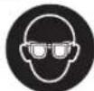
HocTe 3aHTTHOcHna.
Kopnctete cooDBetH ypeH 3a npe6apyBaHe, 3a da H npohajdtcckpneHtene eektpnHn Ka6nn Hn KOncytnpaJte ce co noKaJIHOTo npETnpjatne 3a ChabyaBaBe co eektpnuHa eheprna. KoNTAKTOT co eektpnuHn Ka6nn MoKeJa dOBoeDeNo NoXap nCTpyeH yap. OwtetyBaHTo Ha racobOto MoKeJa dOBoeDeNo EKcnnoHa. HabneryBaHTo BO BoBOOHN cEBKn PpeH3BkyBa OWTetyBaHe.
He n donnpajte 6puchne npounn ndckobnte 3a ceuehe oedeKa He ce onaat. Pnouhte 3a BpeMe ha paabotebeTo cTahyBaat MHory JxwKn.
De6nokpajre ro npeknybaoy3a Bknyybahe/ ncknyyaBaBe H CTabTe Ro BO NsHua JNcknyeHo, DOKOLky ce npekHe HanojyBaBeto Co Ctpyja, Ha np. No Baede He akyMnaTopo. Co Toa Ke cnpeuHte HeKoHTponHaOp peCTapTnpaHe Ha ypeOt.
3aUpcTeTo npaTeTo uTo ce 6pa6OtuBa.10KoKy ro 3auBpCTnte co ypei 3a 3aterHyBaHe HIN MeHReMe, toraI npaTeTo UTo ce 6pa6OtuBa ce pKn nOuBpCto otKoKky co BaWata paka.
He ja otBopajte 6atepujata. Noctoon onacnoct od kpaTOK cnoj.

3aHTeTe ja 6atepHjata od tonnHa,Ha np. Odoonroptajno h3noxyBahe Ha coueBn 3paun, oran, BOa Hbnra. Hny, nocton onachocT od eKcnnoHa.
Pn OwTeYBaBe H HenpOnHcHa yNtpeBa Ha 6aTepnjata MoKeJa H3ne3e NaPea. BHeCte CBex BO3dyx HOKONy HMa NOBpeEH NOpHeTe HdHeCte Tn HaNekap. Papeata MoKe Da Tn HAdpa3HN DnWHTe NaHtTa.
Kopncete ja 6atepnjata cmo 3a noBp3yBahe co BauHOT Bosch npoN3BOd. CaMo Ha ToJ HauHH 6atepnjata Ke ce 3aunTHn OD onaCHO pneONTOBapyBaHe.
Batepjata moke da ce ootetn od octptte npedmetn KAKO HA PP. KINHUN HNN ODBPTYBAU HN CO HADBOPEHNO BNIJAHNE. MoKe Da doJe Do BHATpeuH Kpatok cno J batepjiata moke da ce 3anaH, da nyuHTN qad, da ekCIIIOIPA nHa da ce pnerpee.
BHHMaHHe!PnKOpHCTeBeToHaeneKTPnHOTanat co Bluetooth MoKe Da HactaHaT PpeKn Ha Dpyrnte yPeHN n CNTeMn, ABHOH N MeDnHCKn anapath (Ha np. nejcmejkepn, anapatunha 3a cnuyuahse).NcTo Taka He MoKe ZenocHo Da CE NCKnyu MoXhoCTa 3a NOBpeHa Ha Nyfe HxNBoTH BO HeNoCpeHa OKoJInHa. He ro KopHeTe MepnHOTypeCo Bluetooth Bo 6n3nHa Ha MeDnHcKn YpeH, 6eHnHcKn pymn, Xemnc Kn ypeH, 0bnaTc Ho onacnoT od EKcnno3nJa H BO 6n3nHa Ha MHckn NoIInHa. He ro KopHeTe eNEKTPnuHOT anat co Bluetooth BO ABHOH.
H36erhybajeonroptaja ynotpe6a BO Hpektha 6n3nHa Ha tenoto.
O3HaKaTa co 36OpOBn Bluetooth-KaKo H CnHKnTe (Noroata) ce perHCTpHpaH N TPROBcN MapKn H concTBHeocT Ha Bluetooth SIG, Inc. Cekoe KopHcTeHe Ha OBaa O3HaKa co 36OpOBn/CnKN Ce BpuH Co nHcHua npEky Robert Bosch Power Tools GmbH.
OncnHa npOn3BODOT n nepOpMaHcnte

Ipoountaje nCte 6e36eHocn HanoMeHH ynatCTBa. IpeWKHe HactaHaTH KAKO pe3yntat Ond HenpnpdxjyBaHbe Do 6e36eHocnHe HANOmeHH yNATCTBA MOnke Da npedn3BnKaat eEnKtpnueh yap, NOKAP n/nn
TeuKnIOBpeN.
BHHMaBaJte Ha CnKHe BO npeHnO T eHa yNaTcBTo 3a KopHe.
Ynortpe6a co cooDBeTHa HameHa
EnektpnHnot anate hamehet 3a ceuehe, rpy6o 6pcehe n ueKahe Ha metaJIHH KAMEHN MATEPNJAIb 6e ynoTpeBaHa Boda.
3a cehebe co KOMIOHTHN 6pycn HcpeCTBa MOp a da ce KopnTH cneunjHna 3aunTHa xayba 3a cehebe. PncehebTO BO KAmeH nOprnxKeTe Ce 3a DOBOH BOMyKyBaHe Ha npabTA.
CoIO3B0ENHte anatn 3a 6pycehe enektpnuHnoT anat MoKe da ce kOpNCTn 3a 6pycehe co 6pycha xaptnja. IpaToUHTe nIOdecyBaHaTa Ha enektpnuHnoT anat MoKe da cpehecat npn akTNbnpaHn Bluetooth Low Energy Module GCY 30-4 co nomoHa Bluetooth paNo texHOJOrnJa tmeFey enektpnuHnoT anat mObnHnoT ypeI.
NlyctpupaH KOMHOHeHTN
HymepnpaheToHa cInKHe Co KOMIOHEHTN Ce OJHecyBa Ha npka3OT Ha eNEkTpnuHnO t ana H raPauKuTa CTpaHHua.
(1) NocT3aOTKnyyBaHaHe Ha3aHTTHNtKaNak
(2) Ctpenka 3a npabeue Ha BpTeHe Ha KyKmTETO
(3) Konue 3a 6nokpuhahe Na BpeTeHoTo
(4) LED-paboTHa CBeTHnIka (GWS 18V-10 SC)
(5)User Interface
(6) IpeknhyBa 3a BknyyBaBe/ncknyyBaBe
(7) Kanak 3a Bluetooth-moynot
(8) BaTepeHjaA
(9) Konque 3a OTKJIyUyBaHe Ha BaTeRuJaA
(10)Дононт endpaquka (иоурпа noBpHnHa paKaTa)
(11) 3aunTeH kanaK 3a bpyceHe
(12)Ппклуна ппрабнua co O-прстен.
(13)Бусянna nnoya
(14)БрзоатэнHa Habртka coДржak
(15) NOnHeCTa INoOa OJ TBPd MeTaN
(16) 3aunTeH Kanak 3a ceuehe
(17)ДиСКЗаceuHeA)
(18) PaKa (n30nHa nObPsHnHa ha paKaTa)
(19)BpeTeHo 3a 6pycHe
(20) 3aunnta 3a pauteE
(21)ГуменбypсецнДИСК
(22)Бусесипст
(23) TpkaneHaHaBpTKa
(24) Nohuecta YetKaA
(25)ДиJaMaHTcKa KpyHecTa 6yprJa
(26) Konque 3a npnka303a hano nheocr (GBA 18V...A)
(27)Прикада занони�ст ha batepujata (GBA 18V...)
(28) Konue 3a npnka30 3a HanonHeTOCT (GBA 18V 6.3 Ah, ProCORE18V...)
(29)Пикада занонлесг Дбateрьага (GBA 18V 6.3 Ah, ProCORE18V...)
(30) Xay6a 3a BImyKyBaHbe 3a ceuehe co nIraKn BOINIK
(31)ДиJaMaHTcKNДИСКЗаceuHeA
(32)ПпkaЗанолнeтocTaHaбaTeриjata(User Interface)
(33)Пикада STeNEHOT Ha npTeXoJHO n3bnpaHBe Ha 6pojT Ha BpTeKn (User Interface)
(34) Konue 3a npetxodno H36pahe Ha 6pojot Ha BpTeKn (User Interface)
(35) PnKa3 3a cTarycot Ha eNekTpHnHOT anat (User Interface)
(36) Pnka 3a 3aunrata od ontobapybahe (User Interface)
A) NmyctpnpaHATA HnONnHaHOnpMa He e den OCTaHapdHnOt 6eM Ha HcnpaKa. Cenocnata onpema MoKe Da ja HajTe Bo Hauata Pporpama 3a onpema.
Texnukn noaToun
| Агona брушика GWS 18V-10 C GWS 18V-10 C GWS 18V-10 C | ||
| Б Proj на哪儿/арник | 3 601 JG3 0.. 3 601 JG3 2.. 3 601 JG3 1.. | |
| Hominaelн наон V= 18 18 18 | ||
| Hominaelн б Proj на вретхи мин | 9000 9000 9000 | |
| Б Proj на пазни вретхи мин | -- -- | |
| макс. диамета наSBрушина рпоча мm 100 115 125 | ||
Bosch Power Tools 1609 92A 4B1 (09.05.2018)
332 | MaKeDoHcKn
Aronha6pycnkkaGWS18V-10C GWS18V-10C GWS18V-10C
| Навою на вретенто за брасенье M 10 M 14 M 14 | |||
| мак. долinglyна на habовOT за вретенто за брасенье | mm | 22 22 22 | |
| Исклучва bene при постaten у dap ● ● ● | |||
| Зашпта od рectorыпа bene ● ● ● | |||
| Кочниza за Incфандва bene od брашиа ● ● ● | |||
| Од一件事情а на вретени --- | |||
| Текни сорласно EPTA-Procedure 01:2014 | |||
| - с准备工作 на рачка за падушва bene на Вибрацни | kg | 2,6-2,8 | A) 2,6-2,8A) 2,6-2,8A) |
| - с.stандарда на постенейка рачka kg 2,4-2,6 | A) 2,4-2,6A) 2,4-2,6A) | ||
| Дозвoleна okолна Temпература | |||
| - пriп поныve | °C | 0...+45 | 0...+45 0...+45 |
| - пriп раб teье B) и пriп с重点工作受影响 | °C | -20...+50 | -20...+50 -20...+50 |
| пренихама batepin | GBA 18V... | GBA 18V... | |
| GBA 18V...W | GBA 18V...W | ||
| ProCORE18V... | ProCORE18V... | ||
| пренихама палун | AL 18.. | AL 18.. | |
| GAL 3680... | GAL 3680... | ||
| пренихама палуна за batepin co иndуктнвогл палныe | GAL 18W... | GAL 18W... | |
| П每一个人а doctiven | |||
| Bluetooth* | Bluetooth*4.2 (Low Energy)° | Bluetooth*4.2 (Low Energy)° | |
| Ростожаиме на сигапот | c 888 | ||
| Мakсимален oncesя на сигапot° | m 30 30 30 | ||
A) BO 3aBnCnoT OJ yNtpe6eHeta 6atepnja
B) orpaHnueHa jaunHa npri TEmnpaTyprn < 0^
C) MobHHHte ypeH Mop a da ce kOMnathbHnH co Bluetooth Low Energy ypeHte (Bep3nja 4.2) n da ro noDpKyBaat Generic Access Profile (GAP).
D) Oncerot MOnge MHOry da Bapnpa BO 3aBnCHOCT Ond HauBOpEunHte yCNOB, BkNuyHTenHO npHeMHNKOT wTO CE yNoTpe6yBa. Bo 3aTBoPeHNTE IpocToPnH co MetaHn bapnepn (Ha np. SIOBn, peran, kyepn nTH.) oncerot ha BluetoothMOxke 3NaHTenHO da ce HAmaJIi.
| Агonaбрушика | GWS 18V-10 SC | GWS 18V-10 SC | GWS 18V-10 SC | GWS 18V-10 SC |
| Бpoj на дeн/артник | 3601 JG3 3.. | 3601 JG3 6.. | 3601 JG3 4.. | 3601 JG3 5.. |
| Номинален наюн | V= | 18 | 18 | 18 |
| Номинален bpoj на вртохи | MнH¹ | 9000 | 9000 | 9000 |
| Бpoj на вртохи воразен od | MнH¹ | 4500-9000 | 4500-9000 | 4500-9000 |
| мак. диаметар на брусанта п loча | mm | 100 | 115 | 125 |
| Навон на вретенота за брусаны | M 10 | M 14 | M 14 | |
| мак. должнина на habоJOТ за вретенота за-bрусаны | mm | 22 | 22 | 22 |
| Исклuchува bene рри поbaten удap | ● | ● | ● | |
| ЗашпITA od рectorитраBLE | ● | ● | ● |
MaKeEOHcKn|333
| Агonaьбучения GWS 18V-10 | SC | GWS 18V-10 SC | GWS 18V-10 SC | GWS 18V-10 SC | |
| Кочница за Incфрильные об брзINA ● ● ● ● | |||||
| Од��уновыке наiproл на врутыкINи | |||||
| Текина сordласно EPTA-Procedure 01:2014 | |||||
| - по полнителна рачka за一则душвае на Вибацине | kg 2,6-2,8 | A) | 2,6-2,8A) | 2,6-2,8A) | 2,6-2,8A) |
| - по.stандарна полнителна рачka kg 2,4-2,6 | A) | 2,4-2,6A) | 2,4-2,6A) | 2,5-2,7A) | |
| Дозвoleна okолна Temпература | |||||
| - по полесны "C 0...+45 0...+45 0...+45 0...+45 | |||||
| - посятосы "B) и по скадирале "C -20...+50 -20...+50 -20...+50 | |||||
| пpenорачни батерни GBA 18V... | GBA 18V...W | GBA 18V... | GBA 18V... | GBA 18V... | |
| ProCORE18V... | GBA 18V...W | GBA 18V...W | GBA 18V...W | ||
| ProCORE18V... | ProCORE18V... | ProCORE18V... | |||
| пpenорачни полесни AL 18.. | GAL 3680... | AL 18.. | AL 18.. | AL 18.. | |
| GAL 3680... | GAL 3680... | GAL 3680... | |||
| пpenорачни полесни за сатерни сюндунковни полесны | GAL 18W... | GAL 18W... | GAL 18W... | ||
| П penoc на податои | |||||
| Bluetooth* | Bluetooth*4.2 (Low Energy)C) | Bluetooth*4.2 (Low Energy)C) | Bluetooth*4.2 (Low Energy)C) | Bluetooth*4.2 (Low Energy)C) | |
| Растониме на сигалот c 88 88 | |||||
| мakсимален oncesг на сигалотD) | m | 30 | 30 | 30 | 30 |
A) BO 3aBnCHoCT OJ ynoTpe6eHaTa 6aTeepJa
B) orpahueha jaunna npu temnepaupn < 0^
C) MobHHHTe ypeH Mop a da ce kOMnathbHnH co Bluetooth Low Energy ypeHte (BepaJa 4.2) n da ro noDpkyBaat Generic Access Profile (GAP).
D) Oncerot moke MHory da bapnpa BO 3aBnCHoCT Ond HnBbopeHnTe yCNOBn, BknyuHTenHO n npHeMHNKOT ITO CE yNtpe6yBa. Bo 3aTbOpeHnTe npocToPnn n Co metAnHH bapneHn (Ha np. SIOOBn, peran, Kdyepn nTH.) oncerot Ha Bluetooth MOKE 3auHnTeNo da ce HAman.
HΦopmaunn 3a6yuaBb6paunn
| GWS 18V-10 C | GWS 18V-10 C | GWS 18V-10 C | |
| 3601 JG30.. | 3601 JG32.. | 3601 JG31.. | |
| Вреedingута за(emисда на боча в садуваат соглесно EN 60745-2-3. | |||
| Новото на звк на[elektричны оалат оцеенто с А, тишино Изhecува | |||
| Звун>[при[tсок] | dB(A) | 79 | 79 |
| Звуна щачна | dB(A) | 90 | 90 |
| HесигэрстК | dB | 3 | 3 |
| Hосete за:[тета за:[сухот! | |||
| В kvинITE вреedingута на вибацни[a](векторскь збир на Тли有很大([эдени се bo соглесно co EN 60745-2-3: | |||
| Бухсаны на поsprинни(rрубо[bуся}): | |||
| a_n | m/s² | 6,0 | 6,0 |
| K | m/s² | 1,5 | 1,5 |
| Бухсаны сбухен:[лост: | |||
334 | MaKeJIoHcKn
| GWS 18V-10 C GWS 18V-10 C GWS 18V-10 C | ||||
| a h | m/s2 | 3,5 | 3,5 | 3,5 |
| K | m/s2 | 1,5 | 1,5 | 1,5 |
| GWS 18V-10 SC | GWS 18V-10 SC | GWS 18V-10 SC | GWS 18V-10 SC | |
| 3601 JG3 3... | 3601 JG3 6... | 3601 JG3 4... | 3601 JG3 5... | |
BpeHnOCTHe 3a emncnaHa 6yuaBa ce odpeDyBaat cornacho EN 60745-2-3.
HnBTo Ha 3Byk Ha eNEKtpHHNt anat OueHeTo co A, TnMnHoo H3HecyBa
| Звuchten петенок | dB(A) | 79 | 79 | 79 | 81 |
| Звuchа щашина | dB(A) | 90 | 90 | 90 | 92 |
| НесугностК | dB | 3 | 3 | 3 | 3 |
| Hocete заштENTA за сныхот! |
BkyHHTe BpeHocTH Ha Bn6paunHa (BeKTopcN 36np Ha TpH HAcOKn) H HeCnryphocT K daeneH Ce BO cornaHocCT CO EN 60745-2-3:
TpaJHo CBeTNO 2x3eNeHO≥1/3
TpaJHO CBeTNO 1x3eneHo<1/3
TpenkaBO CBETNO 1 x3eneHO Pe3epBa
DOKOLKY NO pNTHCKaHbE To HA KONHTO (26) He CBETN LEDCBETNka, BatepNJata e DepeKTHa H MOPa da ce 3ameHH.
HanomeHa: HanonHeTocTa ha 6aTeepNJata ce npKaKyaBa Ha User Interface (5) (BNDu,User Interface (BNDn CnkaD), Ctpanua 338).
TpenKaBO CBeTNo 1x3eNeHo 0%
IOKONKY NO npHTNCKaHbeto HA KOnyTo (28) He CBETn HHTy eHaLED-CBeTnKa, batepnaTa eNepeKTHa Mopa Da ce 3aMeHH.
HanoMeHa HanoHeTocTa Ha 6aTeepjata ce npKakxya Hha User Interface (5) (Bnu,User Interface (Bnu Cnka D), CtpaHnca 338).
MOnTHpAbe Ha 3aWHTtEn ypeI
Pepd 6HNO KAKBa HHTepBHeuJHa Ha eEeKtpnHOT anat (Ha np. ODPxyBaBe, 3aMeHa Ha anat nTH.) KaKO npHerOB TpaHCnOpT NCKlaHApBe, H3BaTe ja 6aTepnjatao Hero. PnHEBHNMaTeHNo pNITNCkaHe Ha npeknHyBaOt 3a BknyyBaBe/ACKlyyBaBe NOCTOn ONaCHOCT Ond NobpeDi.
HanomeHa: IopKpIeHTo Ha 6pychata nnoa 3a BpeMe Ha pabotata nn npn oWTeYBaHe Ha ypeOTo 3a npduT ha 3auTHATA xay6a/eneKtpnHnOt anat, toj Mopa Da ce npaTO BO cepBnCHATA cny6b, 3a aPecata NoIeHHeTo BO deIOT CepBnCHA cnky6b u COBeT npn KopncTeHe"
3aHTeKanak3a6pycebe
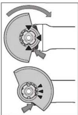
CTabete ro 3aunTHN0T
Kanak (11)Ha npnpaTOT OJ
eNEktpnHNOr anat,doEka
KoDnpanHe 3aun Ha
3aunTHN0r KanaK He ce
nOKnONAT CO npHpAOT.
PnPToa, npTNCHETe r H
dpXeTe Ro nOCTOT 3a
OTKnyBaBe (1).
PnTPHCHe ro 3aunTHN0T
Kanak (11)Ha rpIoTO Ha
BpeTeHOTo DOKeKa BHeCOT
Ha 3aunTHN0r KAnak He
IerHe Ha npnpab6HncaTa Ha
eNEktpnHNOr anat H
BPTeTe r3aUHTHNTOT KaTak DoEka He OcETnTe DeKa CE BKNIOII.
PnoecTe ja no3njujata Ha 3aunTHnTa xay6a (11) cnope nOTpe6He ha pa6oTHnOT npocc. PnTOa, npHTnCHete ro nOCTOT 3a OKJyBaBe (1) Harope n3abPTeTe ro 3aunTHnOT KaNAk (11) BO caKaHaT aNo3njuJa.
Cekoraawoctabaybajrto3aunTHHOTKANAK(11) Taka wTO CHTE 3upBeHH 3anuHaNoCTOT3a
OTKnyyBaBe (1)Ke BnE3aT BO COoDBETHHe OTBOpHa 3aHTTHNt KAnK (11).
Iocabete ja 3aHTHTata xay6a (11) HaToj HauHH WTO Ke ro cnpey netaheTo Ha NCKPN BO npabeu Ha Nneto WTo ja KOpncTn.
3aHTHnOt kAnk (11) cMee da ce BpTn caMo co npTHcKaHe Ha NoCTo 3a OTKnyBaHe (1)! Hnaky, eNEKTPhuHnO anat He Cmee Da CE KOpNCTn MopA da ce npdahe Ha cepBnchata cnxy6a.
HanomeHa:KoHapHHe 3aun Ha 3aHTHTNOT KanaK (11) rapaHTnpaaT,KeHa eNEKTPnHNT anAT MOKe da ce MoHTnpa cAmO eEH 3aHTHTeKanak ITO My OJRObapa.
3aumthaxayba3acehe
PnCeueheTo CO KOMnO3HTH 6pyCN CpeDCTBa ceKoraw KOpHeTe ja 3aHTHTata xay6a 3a Ceuehe (16).
PnCeueBeto BO KAMEH NORPHXeTe Ce 3a DOBOHNO BWMyKByBaHe Ha npaBtA.
3aHTHTa xay6a 3a ceuehe (16) ce MOHTpa KaO 3aHTHa xay6a 3a 6pycehe (11).
Xay6a 3a BwmykyBahe npn ceuebe co nH3raKa BOHNka
3aunTHATAxayba3aceHe coINrAueKN BOINKn (30) ce MOHTnpa kako 3aunTHA xayba 3a 6pyceHe (11).
DOnoJIHHTeHnHa paUka
Kopnctete ro Baunot eneKtpnueh anat camo co dononHntenHa paKa (10).
HaBpTe ja dononHnTeHnTa paKa(10) od DecHO nIO nEOBa HnOroHCKaTa rnaBA BO 3aBnCHOCT OD HaunHot Ha pa6ota.
DOnonHnTeHa paKa 3a npduyBaHe h BaHbpaunHe

IOnonHnntenHata paKa 3a npnduyuBaHbe Ha Bbpaunte OBO3MoKyBa pa6oTehe co mani
Bn6paunn n pnnjataHa n 6e36edna pa60ta.
Bo Hnkoj cnuyaj He ja meHybajTe dononHHTenHaTa paKa.
He ja kopnctete owTeHata dononHHenHa paKa.
3aunTt3a nnAkhnte
3a pa6oTeHe co rymen dNcK 3a 6pyceHe (21)Hn co nonhecta yetka/nIOueCTa yetka/nAmeneCTa 6pycha nOoua cekorau MOHTnpajTe ja 3auNTtata 3a paute (20).
3aucbcte je 3aunntata 3a paueTe (20) coDONHHTENHATA paKa (10).
MOnTnpaHHe Ha 6pyChn anatn
Pepd6HNO KaKaBa HHTepBHeuJa Ha eneKTPnHnOT anat (Ha np. OdpKyBaBe, 3aMeHa Ha anat nTH.) KAKO npHerOB TpaHCnOpT hCKnaHnpabe, h3BaTe ja 6atepJata od hero. PnEBHMMaTeNHO pnttckAbe Ha
IpeKnHyBaUOT 3a BkNpyBaHBe/INCKnyyBaHBe IocToI OanCHOCT OJ NOBpeH.
He n donnpajte 6pynche nnoynnncbohte3a ceuehe dokeka he ce onaat. nnoyte 3a BpeMe Ha paoboteheTo ctahybaat MHory xekn.
IcHCTeTe ro BpTeHTo 3a 6pyceHe (19) n CHTe DeNoBn 3a MOHTnpaBe.
3a3auBpctyBaHe nOla6abyBaHe Ha 6pychnte aIaTH npHTCHETe ro konHTo 3a 6NoKpaHe Ha BpeTeHOTo (3), 3a Da ro 3auBpCTHe BpeTeHOTo 3a 6pyceHe.
PnHTncHETe ro konueTo 3a 6nKpaIbe Ha BpeTeHOTo camo Kora BpTeHOTo 3a 6pyceHe e BO coCTOjBa Ha MnpyBaIbe. HAnky enektpnHnot aJat MoKe da ce OWTETN.
Bpycn nIIOUH/6pyCNn IIOOu 3a ceuehe
BHHMaBaJte HaДmEh3HnTe Ha anaTIne 3a 6pyceHe.
Dinjametapot Ha dynkata Mopa da Ongrobap Ha npknlyuHa npnpabHua. He KopncTeTe aanTepn Hn peyKtopn.
Pn yIOTpe6ata Ha nJaMaHTCKITE 6pyCHN IIOUH 3a CeueHe BHNMABJTe HA ToA, CTpeKATA 3a IpaBeuOT HA BPteHe Ha dJaMaHTCKATA 6pyCHA IIoOa 3a CeueHe Da ce NOKNONyBa Co npabeOTo HA BPteHe Ha eNEKTPNHNOt Anat (NORNEHETe ja CTpeKATA 3a npabeu HA BPteHe Ha NOrOHckata rnaBa).
PepocneIHaMOHTaKaTaMoKeJaCeBnHaTpaHcKaTaCTpaHnua.
3a npuBpctyBaBe KOpHCTe ja 6pyChata nNoa/INCKOT 3a ceuehe 6e3 npyrn anat co 6p3o3ate3HaTATA HABPTKa (14).
KopncTe ja 6p3o3aTe3HaTahabPtka (14) camo co 6pychata nOoA/INCKOT 3a ceHBe do MaKcHMaIe HJJametap on 150 mm.
Bp30aTe3HaTa HABrKa (14)cMee Da ce KopHcTN camo 3a 6pyCNH PIOUH NIN DnCKOBN 3a CeueHe.
Kopnctete camo 6ecnpekopHH, HeouTeHH 6p303aTe3HH HABPTKN (14).
Pn3aterhyBaBe BHMMaBajTe Ha Toa, cTpaHata co HATNMC Ha 6p3o3aTe3HaTa HABPTKa (14) Da He NOKAKyBa KOH 6pyChATA NIO4a.
3a npuBpctyBaHe Ha 6pychata nnoa/duckot 3a ceuehe KOpHCTe ja HcknyuHBO NcnpaHaT a 6p3o3aTe3Ha HABPTka (14).
PnHTNCHETe Ha KOnyTe 3a 6NoKpaHe Ha BPeTeHOTo
(3) 3a da ro 3auBpCTnTe BpeHTo 3a 6pyceHe.3a da ja 3auBpCTnTe 6p03ate3HaTa HApTka
(14),OTBOPETe roHarope
DpkaoyHa 6bp3o3aTe3Hata
HabptKa nCBPTe ja CnHNO
BO npabeu Ha CTpeKNTe Ha
yacOBHHKT. Notoa
npeknonete Ro HADony
Dpkaoy 3aФHKcnpaBe Ha
6bp3o3aTe3HATA HabptKa.He
e DOBONHO 3aTeHyBaBe
Ha pa6oT Ha dNcKOT.
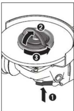
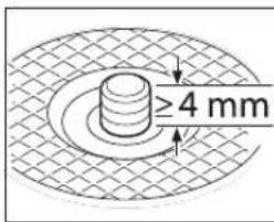
PpOnncho npnucbpcTeHaTa
HHeoUTeTeHa 6p30aTe3Ha
Habptka (14) MoKTe Ja ja
OanabBnte co paka. 3a Toa
OTbOpTe fo Harope
DpaKaHTo Ha 6p30aTe3HaTa
Habptka N CBPTe ja cNlHO
BO npabeC nPoTnBHO Ha
CTpeKNITE Ha cAcOBHHKOT.
Ubpcto 3aTeHata
6p30aTe3Ha Habptka
HNKORAaw He ja OdBpyBaJte
co anat, Tyky yNoTpeBeTe
Knuy Co Dba OTbOpn.
IIO MONTaKaTa Ha npKnyHaTn pnpa6Hnua Ha 6pychata nOoua/ dCKOT 3a CeueHe cNo6OHaT aOnJnHa Ha HABoJOt Ha 6pyChOTO BpeTeHO Tpe6a Da n3HeCyBa Hajmanky 4 mm.
BHHMaBajTe Ha cBpCTo BkIOnyBaHc Ha anaTOT 3a 6pyceHe, Taka ITO Hema Da ce ODBpTH O D BpeTeHO To KaPajO d eneKTPuHnOT anat.
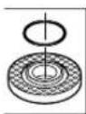
Bo npknnyhata npnpabnna (12)okony BeneoT 3a ceHTpnpahe e cTaBEN nactuH den (O-npTeH).DOKONky Heoctnra OnpCTeHOT HnE oWTeH, npKnnyHATA npnpabnna (12)Mopa da ce 3amEHn Ppe
noHaTaMoUHa yNoTpe6a
P MoTakata Ha anatot 3a 6pycehe, nped Bknyybahe, npOBepete daHToj e ToHQ MOHTpan H daHMOKe cNo6OHO da Ce BPTN. PpOBepete daH anatot 3a 6pycehe He ctpyra Ha 3aHTTHata Xay6a Hn Dpyrnte DenOBH.
Iamenecta 6pycha nnoa BO BnHa Iane3a
Ppna6oTeHbeto co namenecTa 6pycha nnoa ceKorau MoHTnpajte ja 3auHTnTata 3paqete (20).
TymenDnck3a6pycebe
Ppna6oBeTeO co rymen dck3a 6pycebe (21) cekora mOnThnpajte ja 3auTnTata 3paqete (20).
PepocneIOT Ha MOHTaKaTa MoKe Da ce BnH Ha rpaHcKaTakapTa.
CTaBeTe rO rMyMeHnOT 6pyceH nIck (21) Ha 6pyChoto BpeTeHo (19).
UbpcTo npntncheTo 6pyChnOT nIcT (22) Ha donHata CTpaHa Ha rymeHnO7 6pyceH dNCK (21).
Habptete ja Tpkane3HaTahabptka (23) 3aterheTe ja co Knyu Co nBa OTBOpN.
TOnueCTa ueTka/nnoueCTa ueTka
Pn pa6oBeTo co noHueCTa Hnn nnoeCTa Yetka ceKoraw moHTnpajte ja 3aunrtata 3paute (20).
PeOcneIOT Ha MoTaKaTa MoKe Da ce BnHa rpaHkata KapTa.
Nouectata/nnoueCTata ueTka Mopa da ce Habptn Ha BpeTeHOTa 3a 6pycehe dokeka ubpcto He HanerHe Ha npapaBnucata Ha BpeTeHOTa 6pycehe Ha Kpaot Ha HaboJOT ha BpeTeHOTa 6pycehe. 3aTeHrTe ja Nouectata/nnoueCTaueTka CO Bnnykact Knuy.
IOnueTa nnoua oUcbpT Metan
Ynortpe6ata Ha IOnueCTa IIoua e Do3BoneHa cMo co COOdBETeH 3auHTHe KAnK.
D03B0JIeHn anaTH 3a 6pyceHe
MoKeIaTnKOpHCTHeCHTe aIaTH3a6pyceHe HabeTeHN BO Oba yNaTcTB0 3a yNoTpe6a.
D03B0eHnO7 6poj Ha BpTeKn [MnH1] Odn. nepHepHaTa 6p3Ha [m/s] Ha yNtpe6eHnO7 anat 3a 6pycehe Mpa da OndroBaHa NaDatoUte BO CneHnata TaBeNa.
3aToa BHMMaBajTe Ha 03BOHeHnO 6poj Ha BpTeKx OdH. nepHepHata 6p3nHa Ha etHKeTAt Ha anatot 3a 6pyceHe.
| MaKc. [mm] [mm] | ||||
| D bd [mMn] | 3] [m/s] | |||
| 100 | 7 | 16 | 9000 | 80 |
| 115 | 7 | 22,2 | 9000 | 80 |
| 125 | 7 | 22,2 | 9000 | 80 |
| 150 | 7 | 22,2 | 7500 | 80 |
| 100 | - | - | 9000 | 80 |
| 115 | - | - | 9000 | 80 |
| 125 | - | - | 9000 | 80 |
| 150 | - | - | 7500 | 80 |
7530M14900045

82-M14900080
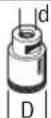
BpTeBe ha noroHckata rnaBa (GWS 18V-10 C)
Pepd 6nno KaKbHa HHTepBHeuJa Ha eJekTpHnHOT anat (Ha np. ODPKyBaBe, 3aMeHa Ha anat nTH.) KaKo H np HerOB TpaHCnOPT NCKnAHPaBe, h3BaTe ja 6aTepnjata O hr. Pnp HeBHNMaTeHNO pntnCkAnBe Ha npEKNHyBaOT 3a BkNpyBaIe/NCNpyBaIbe NoCTOn ONaCHOCT Ond NobpeiN.
338|MaKeDoHcKn
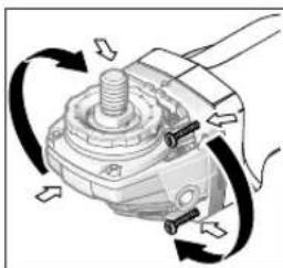
Iorohckata rnaBa moKe da ja BpTnTe co yekOp nO 90^ PnToa, npkeHyBaoyo3a BKnyuBaBe/NCkNyUbaHe 3a CnejuAnHe CnyaHa paBota MoKe Da ce NoCTABN BO nonOBonHa no3nJHa 3a pakyBaHe, Ha np.3a neBopaknIua.
UeNoCHO OJBPTe r4-Te 3aBPTKn. BHIMATEHNO HABanE ja norOHckata gnaba n6e3 da ja h3BaHTe OD KkyKHTeO CTabe ja BO HOBA tno3nju. IOBTOHO HABPTe r4-Te 3aBPTkn.
BcncyBaHe Ha npab/ctpyrotHH
PpABTo oMATEpHjAnIte kako Ha np. cNoEBn 6oJa, HeKoN BnOBOv nDpBO, MNHePAJn H meta MoKe Da 6nide WTeHa No 3dpaBJeTO. DOnnpaBeTo NnBnWyBaHbeto Ha TaKBaT aPab MoKe Da npeiN3BnKa aneprncKn peakun n/nn 3a6onyBaHa Ha dNshInTe NaTHuHa KOpNCHKOT nn Nn Nnata BO OKONHHata.
OndepenueyecnKnpaKaKaHa np. npaB odJa6 nHb6ka Baxkat KaKa KaHcpePoreHn,OC6eHo DOKoJIky Ce BO KOM6HnaJca DoOnONHTeHN CyntaHn (xpomat, cpeCTBa 3a3aHTa Ha npBo).MATEPNJAnTe WTo COpKnat a36ecT CMeT Da 6uDat O6pa60YbAHn Camo od CTpaHa Ha CTpyHN Nua.
-
IorpnkeTe ce 3a do6pa npoBepenocHa pa60HTO MecTo.
-
Ce npenopayba Hoche Ha macka 3a 3auTnTa npn BduyBaBeTo co Knaca Ha qntep P2. BHmabajte Ha BaxeKITE nponnc Ha Baata 3emja 3a MaTepnjantO KoJ ro o6paBotyBate.
M36erHyBaJte co6npaBe npabHa pa6oTHOTMeCTO. PpaBtAJeCHO MOKe Da ce 3anAn.
Ynortpe6a
CtabaBe Bo ynOtpe6a
BmTeHyBaIbe Ha 6aTepujata
HanoHetaTata 6aTePnja (8) npHTncHete ja OAnpeD nABHaTpe BO noHOxJeto Ha eNeKtpnHnO T aNaT,doEka He ce 3aknyn 6aTePnjata.
BknyyBaBe/ncknyuYBaBe
3a CTabaHe BO ynoTppe6a Ha eneKtpnHnO t anat, nI3HeTe r O npeknHyBaHT 3a BknyyBaHe/NCKyuYBaHe (6) Hahanpe.
3aФнсраHe NaPpeKHyBaOT 3a BknyBaBe/ NCKnyBaBe (6) npHnCHete FO ppeKHyBaOT 3a BknyBaBe/NcknyBaBe (6) HanaPeHaOny DoKeKa He CE BKNoH.
3a da ro ncknyte enektpnunnoT anat,ocnofoede ro npkeHyBaOT 3a BknyyBaBe/nckyBaBe (6) Ond. dokolky toe 6nokpan, kpatko npntchete ro npkeHyBaOT 3a BknyyBaBe/nckyBaBe (6) Hanaad handoNy ntoa ocnofoede ro.
Pepn ynoTpe6ata npOBepete rnaAATNE 3a 6pycehe. Anatot 3a 6pycehe Mopa da 6nde MOHTnpaH 6ecnPekpHO n da MoKE cno6oHNO da CE BPTN. HAnpABeTe np6a od Hajmanky 1 MNHyTA 6e3 ontobapybahe.He KopHCTe OWTetEH, HETPKane3HN Hn anATn 3a 6pycehe wTO B6hpaaat. OWTetEHnTe anATn 3a 6pycehe moKe da nyKHAT n da npedn3BnKaat NOBpeH.
IcknyBaBe npn nobpaTeh yap

PnHnAeJha npeyKaHa enEKeTpnHnOtn aat,
Ha np. 6NoKpaHe Ha pe30 npn CeeHe,
DOBOOT HA CTpyJa DO MToPOT eEnEKe TPOHcKN Ke ce npeKnHe. PnToa LED-pa6oTHata CBETnKa
(4) Tpenka beno,a pnpka3oT 3a CTatyc (35)
UpBeHo.
3a NOBTOPO BKNJyBaHBe npeKnHyBaOT 3a BKNJyBaHBe/ NCKNjyBaHBe (6) CTABeTe Ro BO nOLOXbA NcknyeHO n OndHO BKNJyTe Ro eNEKTPNHOT anat.
3aHTHa opeTaptnpahe
3aHTnata od pectapnpabe ro cnpeyuBa
HEKoHTpOlnpaHOT BknyyBaBe Ha eNekTpHnOt aHa Tn
npeHH ha cTpyja.
PnA kTHBnPaHa 3aHTnTa od pectapnpabe, npKa30T 3a
CTatyc (35) Tpenka upBEHO.
3a nobTOPHO BknyBaBe cTaBete ro npeKHyBaOT 3a BknyBaBe/HckNvYBaBe (6) BO NcKnyeHa No3njuA OJHOBO BknyTe Ro eNeKtpHnOHT aat.
NcknyyBaIbe npu yap
HnterpnpaHOTncknyBaBe npydpar ngcknyuBa eneKtpnHnO aIaT,ITOM no naCe hajde Ha 3emjata. Pnptno npkka30 3aCTaYc (35) TpeNka UpbEHO. 3a NOBtpho BknyBaBe CTABeTe r peKHyBaOT 3a BknyuBaHe/NCKyUBaHe (6) BO ncknyeHa No3uJna j ONDHO BKnyeTe r eNEKtpnHnO aIaT.
User Interface (BnDn CnNkA D)
User Interface (5) cnkykn 3a n36bnpahe Ha 6pojot Ha BpTeKn, KaKO H3 a npKaKaKyBaHc Ha cocToj6Ta Ha eNeKTpyHnOT anat.
IpeTxoJHO 36bpahe Ha 6poj Ha BpTeKn (GWS 18V-10 SC)
Co konqueto 3a n36op ha 6poj ha BpTeKn (34) Moxe da ro n36epete Notpe6Hnot 6poj Ha BpTeKn H3a Bpeme Ha pa6otata. IpaToUte BO npInnoKeHaTa 6eBa ce npenopauAHBpeHnocTH.
MaKeDoHcN|339
PnceheTo co6pycnHnOoucKcogarpaBOTe Co yMepennoMeCTyBaHeHaHApedNoMaTepnJant. He npaBeTe pnpTnCOK Ha 6pyChata nOua 3a cepebe, He HabanybaTe Hneocnnpajte.
He n6nokpajte 6pycnHTEIIOU3acehebe70
H3neryBaatCoCTpaHueHnPOTHBnPHTNCOK.
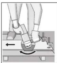
EneKTPnHnO anat ceKOraM Mopa Da Ce BOnu BO CnpOTNBEN IpabeHu DAHNKeHe. Hnky nocToN onaCHOCT, ToJ
HEKOHTpOHHaNo Da ce HCTINcHe OJ pe3OT.
PnCeueHeHa npoФmHn HcTnpaRoaHnueBKn, HajdoBoe da NoCTaBHTe Ha HajMaHOT npeCek.
CeueheHaKaMeH(BnDcnKcA C)
PnCceHbTo BO KAMEH NOrpnXeTe Ce 3a DOBONHO BmkyBaHe Ha npaBt.
HoceteMacka3a3awTHTa0npab.
EneKtpnHnot anat Cmee da ce KopnCTn cmo 3a ceuehe/6pycehe Ha cyBu MaTepnjann.
3a cehe he Kaemen hajno6po e da ynotpe6nte 1njamHTcKa 6pycha nOua 3a cehe.
PnKOpNCTHe Ha xaybata 3a BCNCyBaHBe 3a ceuehe co nI3rauKn BODnKn (30) BCNCyBaHT Ha npab Mopa da 6nde OoBonen 3a BCNCyBaHe Ha npabTa oK kAMEhot. Bosch rH ydn COOdBETNHTE BCNCyBaHn Ha npab.
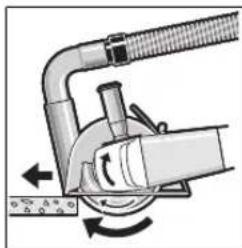
BknyeTe ro enektpnHnoT
anat nocTaBeTe ro co
npedHnot den Ha
n3raqKne To BODnKnHa
denot wTo ce o6pabotya.
PomectybaJte ro
eneKtpnHNoT anat co
ymepeno DnXkeJe no
matepnJaNot wTo ce
o6pabotya.
PnCeHeHaOc6eHoUBCPTMaTepnJaanHa np.6ToH co YaKan, DnJaAMHTCKATA 6pycha NIOOa 3a CeHe MoKe Da ce nperpee Hda CEOTBHeIOTNCKPN Koj KpyKn OKoJy DnJaAMHTCKATA 6pycha NIOOa 3a CeHe Jacho yKaKyBa Ha ToA.
Bo takoB cyuyaj npeknHete ro npocet ha cehe ne octabeTe ja kpaTko nJaMaHTckata 6pycha nNoa 3a cehebe Bo npaseh od npn HajBcOK 6poj Ha BPteKn, 3a da ce ona. 3HauntenHO nonyUtahe Bo pa6otata H BHeeOt od NCKpn KpkyKn Ce 3Haun 3a OtaNeHa nnJaMaHTcka 6pycha nIOua. Moke noBtopHo da ja haoCTpTe co KpaTK pe3OBn BO abpa3HBen Maepinjan, Ha np. CnNkATEH KAMH.
HanomeHH 3a cTaTHKaTa
IpoeHNTBOHOceKHTSEHNOBHNIOJIeXaH HOpMaTADIN1053en1nnnpoNcHTEcneuΦnUHHa3emjata.Mopa3aONKHTENHOacpePnDpKByateOOBnnpOnCH.PednoTeKOTHa pabotata NObHKajTe oOJROBOPHmCTaTHAP,apxNTKTnHnHAdNEXKHITepaDeKHNpaKOBODHTEN3a da CEcoBetyBaTe.
HanomeHH 3a ONTHMaHNO KOpHcTeHe Ha 6aTePnHTe
Ten./paKc:02/2467610
Mo6.:070595888
D.I.T.Y "POJKA
JaHnyKpOBcKn 66;T.LI ABTOKOMaHaJa NOKaI 69
1000 Ckonje
E-nouira: servisrojka@yahoo.com
Ten: +389 2 3174-303
Mo6: +389 70 388-520, -530
TpaHcnpot
JHym-johcKte 6atepnnoJeKaHa 6apaBaTa Ha 3aKOHOT 3a onachn MaTepnjann. Batepnite MoKe da ce TpaHCNOPTnpaat cmo O cTpHaHa KOpNCHKOT, 6e3 Notpe6a od donoHHTENH KBaINΦkaunn.
Pn npenoc Ha nctte Od ctpaHa Htptnuca (Ha np. Bo3dywen TpaHcnpot HnH upeNduja) HeonxOJHO e da ce BHNMAba Ha cneunjahnite HanomEnHa aMbaXata n 03haknte.Bo takoB cnuyaj, npn oIroTOBkata Ha npatkata Mopa Da ce Nobka ekcnepT3a onacnCynCTAHU.
TpaHcnpaJte R6atePnnte cAmOdoKoNky KkyuTeToe HeouTeTeHO.3aIenete rN OTBopeHnTE KOHTN n CnakyBaJte ja 6atePnjata Ha ToJ hauHn HTO HeMa Da ce DbHKn BO aMbaJaxata.Be MoIIme BHMabajTe Ha EBeHTyAInHe TOnONHnTeHNHaUMOHaHn IpONHCn.
OcTpaHyBaIbe

EnektpnHne anapatn,6atepHnte,onpeMaTa n ambaJnKte Tpe6a da ce otctpaHat Ha ekolouknpnФaTnBHaun.
He nФрпajte eneKtpuHnTe anapathn 6aTepeHnTe BO DOMaunHATA KaHt a 3a rHy6pe!
Cama 3a 3emjnte oEY:
CnopeE EBpONckata perynatBa 2012/19/EU
eNEKTPnHnTE anapATn UTo ce BOH yNoTpe6a nDepeKTnTe
HnN NcKOpNCteHnTE 6aTePNn CnopeD perynatBaTa
2006/66/EC mopa oDennO da ce coBepa n da ce
peuKnnpaaT 3a nobTopHa yNoTpe6a.
Batepn:
JIHTHM-JOHCKH:
Be MoJIHMe BHNIMAbajTe Ha HAnOMeHHe Bo DeNoT TpaHCnOpT (BnDn „TpaHCnOpT", CtpaHnca 341).
Srpski
Ugaona brusilica GWS 18V-10 C GWS 18V-10 C GWS 18V-10 C
| Broj proizvoda | 3 601 JG3 0.. 3 601 JG3 2.. 3 601 JG3 1.. | |||
| Nominalni napon V= 18 18 18 | ||||
| Nominalni broj obrtaja min | 1 | 9000 9000 9000 | ||
| Broj obrtaja na prazno min | 1 | - - - | ||
| Prečnik diska mm 100 115 125 | ||||
| Navoj brusnog vretena M 10 M 14 M 14 | ||||
| maks. dužina navoja brusnog vretena mm 22 22 22 | ||||
| Povratno isklučivanje | ● | ● | ||
| Zašita od ponovnog kretanja | ● | ● | ● | |
| Inerciona kočnica | ● | ● | ● | |
| Biranje broja obrtaja | - - - | |||
| Težina ogovara EPTA-Procedure 01:2014 | ||||
| - sa dodatnom ručicom za amortizovanje vibracija | kg | 2,6-2,8A) | 2,6-2,8A) | 2,6-2,8A) |
| - sa standardnom dodatnom ručicom kg | 2,4-2,6 | A) | 2,4-2,6A) | 2,4-2,6A) |
| dozvoljena sobna temperatura | ||||
| - prilikom punjenja | °C | 0...+45 | 0...+45 | 0...+45 |
| - u raduB)i prilikom skladištenja | °C | -20...+50 | -20...+50 | -20...+50 |
| preporučeni akumulatori | GBA 18V... | GBA 18V... | GBA 18V... | |
| GBA 18V...W | GBA 18V...W | GBA 18V...W | ||
| ProCORE18V... | ProCORE18V... | ProCORE18V... | ||
| preporučeni punjači | AL 18.. | AL 18.. | AL 18.. | |
| GAL 3680... | GAL 3680... | GAL 3680... | ||
| preporučeni punjači za induktivne akumulatore | GAL 18W... | GAL 18W... | GAL 18W... | |
| Prenos podataka | ||||
| Bluetooth* | Bluetooth*4.2 (Low Energy)C) | Bluetooth*4.2 (Low Energy)C) | Bluetooth*4.2 (Low Energy)C) | |
| Ostojanje signala | s 888 | |||
Ugaona brusilica GWS 18V-10 C GWS 18V-10 C GWS 18V-10 C
| maksimalni domet signalaD | |
| m 30 30 30 | |
| A) | zavisi od upotrebljene akumulatorske baterije |
| B) | ograničena snaga pri temperaturama <0°C |
| C) | Mobilni krajnji uredaji moraju biti kompatibilni sa Bluetooth®-Low-Energy uredajima (verzija 4.2) i moraju podržavati Generic Access Profile (GAP, Profil za genericki pristup). |
| D) | Opseg moze veoma varirati, u zavisnosti od spojašnjih uslova, uključujuci i upotrebljeni prijemnik. Unutar zatvorenih prostorija i kroz metalne prepreke (npr. zidove, police, koferi i sl.) opseg dopiranja Bluetooth®-a moze biti znatno manji. |
| Ugaona brusilica GWS 18V-10 | SC | GWS 18V-10 SC | GWS 18V-10 SC | GWS 18V-10 SC | |
| Broj proizvoda | 3601 JG3 3.. | 3601 JG3 6.. | 3601 JG3 4.. | 3601 JG3 5.. | |
| Nominalni napon V= 18 18 18 18 | |||||
| Nominalni broj obrtaja min | -1 | 9000 | 9000 | 9000 | 7500 |
| Broj obrtaja na prazno min | -1 | 4500-9000 | 4500-9000 | 4500-9000 | 4000-7500 |
| Prečnik diska mm 100 115 125 150 | |||||
| Navoj brusnog vretena M 10 M 14 M 14 M 14 | |||||
| maks. dužina navoja brusnog vretena mm 22 22 22 22 | |||||
| Povratno isklučivanje | ● | ● | ● | ||
| Zašita od ponovnog kretanja | ● | ● | ● | ● | |
| Inerciona kočnica | ● | ● | ● | ● | |
| Biranje broja obrtaja | ● | ● | ● | ● | |
| Težina ogovara EPTA-Procedure 01:2014 | |||||
| - sa dodatnom ručicom za amortizovanje vibracija | kg | 2,6-2,8A) | 2,6-2,8A) | 2,6-2,8A) | 2,6-2,8A) |
| - sa standardnom dodatnom ručicom kg | 2,4-2,6 | A) | 2,4-2,6A) | 2,4-2,6A) | 2,5-2,7A) |
| dozvoljena sobna temperatura | |||||
| - prilikom punjenja | °C | 0...+45 | 0...+45 | 0...+45 | 0...+45 |
| - u raduB)i prilikom skladišenja | °C | -20...+50 | -20...+50 | -20...+50 | -20...+50 |
| preporučeni akumulatori | GBA 18V... | GBA 18V... | GBA 18V... | GBA 18V... | |
| GBA 18V...W | GBA 18V...W | GBA 18V...W | GBA 18V...W | ||
| ProCORE18V... | ProCORE18V... | ProCORE18V... | ProCORE18V... | ||
| preporučeni punjači | AL 18.. | AL 18.. | AL 18.. | AL 18.. | |
| GAL 3680... | GAL 3680... | GAL 3680... | GAL 3680... | ||
| preporučeni punjači za induktivne akumulatore | GAL 18W... | GAL 18W... | GAL 18W... | GAL 18W... | |
| Prenos podataka | |||||
| Bluetooth* | Bluetooth*4.2 (Low Energy)C) | Bluetooth*4.2 (Low Energy)C) | Bluetooth*4.2 (Low Energy)C) | Bluetooth*4.2 (Low Energy)C) | |
| Ostojanje signala | s | 8 | 8 | 8 | 8 |
| maksimalni domet signalaD) | m 30 30 30 30 | ||||
A) zavisi od upotrebljene akumulatorske baterije
B) ograničena snaga pri temperaturama <0°C
C) Mobilni krajni uredaji moraju biti kompatibilni sa Bluetooth -Low-Energy uredajima (verzija 4.2) i moraju podržavati Generic Access Profile (GAP, Profil za genericki pristup).
D) Opseg moze veoma varirati, u zavisnosti od spojaasniju uslova, uključujuci upotrebljeni prijemnik. Unutar zatvorenih prostorija i kroz metalne prepreke (npr. zidove, police, kofere i sl.) opseg dopiranjia Bluetootha -a moze biti znatno manji.
348 | Srpski
Uldised ohutusnouded
HOIATUS
Lugege labi koki ohutusnouded ja juhised. Ohutusnouete ja juhiste
eiramise tagajärjeks voib olla elektrilök, tulekahju ja/voi rasked vigastused.
Bluetooth Low Energy mooduli GCY 30-4 paigaldamine
m = 311 ;
SC
SC
SC
Km/s
2
1.5 1.5 1.5 1.5
Sajamaicibnorditais svarstibu limenis ir izmerits atbilsto standtata noteiktajai procedurai un var tikt izmantots elektrinstrumentu savstarpejai salidzinasanai. To var izmantot ari vibracijas raditas papildu slodzes ieprieksejai novertesanai.
Seit noraditais vibracijas limenis ir attiecinams uz elektroninstrumenta galvenajiem pielietojuma veidiem. Ja elektron instruments tiek lietots netipiskiem merkiem, kopar netipiskiem darbinstrumentiem vai nav vajadzigaja veida apkalpots, ta vibracijas limenis var atskirties no seit noraditas vertibas. Tas var butiski paliinat vibracijas radito papildu slodzi kopejam darba laika posmam.
Lai precizi izvretetu vibracijas radito papidu slodzi zinamam darba laika posmam, janem vera ari laiks, kad elektron instruments ir izslegts vai ari darbojas, tacute faktiski netiek izmantots paredzeta darba veiksanai. Tas var butiski samazinat vibracijas radito papidu slodzi zinamam darba laika posmam.
Veiciet papildu pasakumus, lai pasargatu stradajo so personu no vibracijas kaitigas iedaribas, piemeram, savlaicigi veiciet elektroinstrumenta un darbinstrumentu apkalposanu, uzturiet rokas siltas un pareizi planojiet darbu.
Montaza
Bluetooth Low Energy modulo GCY 30-4 jevietosana
4Norade: elektrijnstrumentiem GWS 18V-10 C Bluetooth Low Energy modulis GCY 30-4 ir pieejams ka piederums; elektrijnstrumentiem GWS 18V-10 SC tas ietilpst standarta piegades komplekta.
Lai uzzinatu vairak par Bluetooth Low Energy moduli GCY 30-4, lasiet atticigo lietosanas instrukciju.
Akumulatora uzlade
Lietojiet tikai piederumu lappuse noraditas uzlades icerices. Vienigi sis uzlades icerice ir piemerotas, lai uzladetu jusu elektroinstrumenta izmantojamo litija jonu akumulatoru.
Piezime. Akumulators tiek piegadats dalji uzlade tstavokli. Lai izstradajums spetu darboties ar pilnu jaudu, pirms pirmas lietoanas pilnigi uzladejiet akumulatoru, Kievienojot to uzlades iceriei.
Litija-jonu akumulatoru var uzladet jabkura laika, nebaidoties samazinat t kalposanas laiku. Akumulatoram nekaite ari partraukums uzlades procesa.
Elektroniskas elementu aizsardzibas (ECP) funkcija aizsarga litija-jonu akumulatoru pret dzilo izladi. Ja akumulators ir izladejies, ipasa aizsardzibas sistema izsledz elektroninstrumentu: sada gadijuma darbinstruments partrauc kustetes.
Ja elektroinstruments ir automatiski izsledzies, nemeginiet to no jauna iesegt, nospiezot iesledzeju.
Sadas ricibas del var tikt bojats akumulators.
levrojiet noradijumus par atbrivoanos no nolietotajiem izstradajumiem.
Akumulatora iznem'sana
Akumulatoram (8) ir divpakapju fiksators, kas nejauj tam izkrist, ja nejausi nospiez akumulatora atblokesanas taustinu (9). Kamer akumulators ir ievietots elektroninstrumenta, to vieta notur atspere.
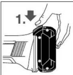
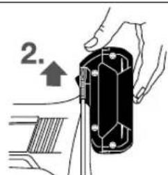
Lai iznemtu akumulatoru (8) nospiediet atblokeesanas taustinu (9) un izvelciet akumulatoru no elektroninstrumenta uz prieksu. Nevelciet parak specigi.
Akumulatora uzlades stavokla radijums (akumulatoratips GBA 18V...) (skatiet attelu A)
Akumulatora uzlades stavokla radijuma (27) tris zalas LED uzrada akumulatora (8) uzlades stavokli. Drošibas apsverumu del uzlades stavoklis uzradas tikai tad, kad elektroinstruments ir miera stavokli.
Lai redzêtu uzlades stavokli, nospiediet taustinu (26). To var izdarit ari tad, ja akumulators (8) ir iznemts no elektroinstrumenta.
LED letilpiba
Pastavigi deg 3 zalas LED ≥ 2 / 3
Pastavigi deg 2 zalas LED ≥ 1 / 3
Pastavigi deg 1 za la LED < 1/3
Mirgo 1 zaja LED Rezerve
m = 311
18V-10
GWS 18V-10
m = 311 ;
GWS 18V-10
SC
3601JG33...3601JG36..3601JG34..3601JG35..
TJHJIiJiJiJiJiJiJiJiJiJiJiJiJiJiJiJiJiJiJiJiJiJiJiJiJiJiJiJiJiJiJiJiJiJiJiJiJiJiJiJiJiJiJiJiJiJiJiJiJiJiJi
甲
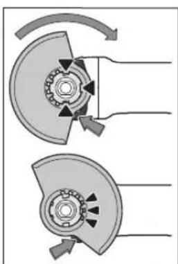
鍙BRerSi/DiStKBrERiN是,SπTnLnAa
凿,有在,SπTnLnPnLnRtEeBnRtEeBnRtEeBnRtEeBnRtEeBnRtEeBnRtEeBnRtEeBnRtEeBnRtEeBnRtEeBnRtEeBnRtEeBnRtEeBnRtEeBnRtEeBnRtEeBnRt
卡巴伊德川
凶歟者音用歟,逢用是,不
哉樂
i
音 ~ 用 ~ _ 用 员园,[rp]和猿习, m / s 是 1
T
上
| [mm] [mm] | ||||
| D b d [min] | -1 [m/s] | |||
| 100 | 7 | 16 | 9000 | 80 |
| 115 | 7 | 22.2 | 9000 | 80 |
| 125 | 7 | 22.2 | 9000 | 80 |
| 150 | 7 | 22.2 | 7500 | 80 |
| 100 | - | - | 9000 | 80 |
| 115 | - | - | 9000 | 80 |
| 125 | - | - | 9000 | 80 |
| 150 | - | - | 7500 | 80 |
| 75 30 M 14 9000 45 |
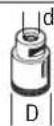
82-M14900080
giher hdt 18V-10 C)
→連同公上青中音(包本正电贝及电贝

ger HeDn90°
geo 1000
.
K
J
J
J
J
J
J
音者,皆。
版式日
30-4 羽绒 30-4 羽绒 30-4 羽绒 30-4 羽绒 30-4 羽绒 30-4 羽绒 30-4 羽绒 30-4 羽绒 30-4 羽绒 30-4 羽绒 30-4 羽绒 30-4 羽绒 1
#
a aalaaal aalaaal aalaaal aalaaal aalaaal aalaaal aalaaal aalaaal aalaaal aalaaal aalaaal aalaaal aalaaal aalaaal aalaaal aalaaal aalaaal aalaaal aalaaal aalaaal aalaaal aalaaal aalaaal aalaaal aalaaal aalaa
Lg aLiJIg aJUjEJI I
0dlll ldlil pdool jglj 1000000000000000000000000000000000000000000000000000000000
Jbaleaiee 15 1 aiee e 10 10 10 10 10 10 10 10 10 10 10 10 10 10 10 10 10
0e 1000000000000000000000000000000000000000000000000000000000000
aalagolall aolal algll aolal yaiy jayl 100000000000000000000000000000000000000000000000000000000000000000000000000
J 1 J 1 J 1 J 1 J 1 J 1 J 1 J 1 J 1 J 1 J 1 J 1 J 1 J 1 J 1 J 1 J 1 J 1 J 1 J 1 J 1 J 1 J 1 J 1 J 1 J 1 J 1 J 1 J 1 J 1 J 1 J 1 J 1 J 1 J
g aaiall
11 11 11 11 11 11 11 11 11 11 11 11 11 11 11 11 11 11 11 11 11 11 11 11 11 11 11 11 1

JUg21 111 00000000000000000000000000000000000000
yaaollll
ai jssllolalgbabaaasao ayulgSsll 6.ellal psswUgs lqagog qkausg aboll sic gboo Jols aylgubc poaawu Uy aabjallalldgo abwgl
gab sic aigls lac baw oegy jgi lc w
Jgagawll gulol oaiwU 0jaiu1gl uaiuauuuiuuiuuiuuiuuiuuiuuiuuiuuiuuiuuiuuiuuiuuiuuiuuiuuiuuiuuiuuiuuiuuiuuiuuiuuiuuiuuiuuiuuiuuiuuiuuiuuiuuiuuiuuiuuiuuiuuiuuiuuiuuiuuiuuiuuiuuiuuiuuiuuiuuiu
oJL aJ Ll Jg Ull Jn Low Bluetooth Ug gUgLo sic uUgSJI Ug Ug Energy Module GCY 30-4 Uu uug uuu Bluetooth uuiu
oJgaaal1j2
oJgWjI oJgWJI jzJI aJyJ W J 10000000000000000000000000000000
a[gjlllJaiyJgj
Jcill lglgwlolxip
(3)
(GWS 18V-10 SC)LEDJaaJIa
puaaiae>1g (5)
Jy/1jssu 6
Bluetooth Jggo cUaC (7)
(8)
(9)
(jgjoo jajgabw)oljao (10)
aJUULI aJIgJIeJIc (11)
a aaii iil glll lllllllllllllll
aJgall sball sgal gl Jaal Jau
aJgJgJ1JdJ
.
aallogbgl aagll aaiy oajgol
logblaaa aall alas yn ggl. 0eall
aalogll aalll lgl yd jy d aay
. 1j 1j 1j 1j 1j 1j 1j 1j 1j 1j 1j 1j
Jggbaloljglalllall 1
gog Jc alolglablyg jzull glaJlaIaJ 0
Jx: yio. jyssll Jullsly Igbloic ably
.09 o gnil lslg iio ayu. sallj
aall Jzlll aeb9, jzlallae b9 nol 10000000000000000000000000000000000000000000000000000000000000000000000000
aaiy0gjll aajrgsll oolal 1234567890000000000000000000000000000000000000000000000000000000000000000000000000000000000000000000000000
Lg LgJg Bluetooth aJoo pWl Bluetooth SIG, aJoo Joo aJoo Joo Joo Joo Joo Joo Joo Joo Joo Joo Joo Joo Joo Joo Joo Joo Joo
| GWS 18V-10 C | GWS 18V-10 C | GWS 18V-10 C | ggljlllalalalalalalalalalalalalalalalalalalalalalalalalalalalalalalalalalalalalalalalalalalalalalalalalalalalalalalalalalalalalalalalalalalalalalalalalalalalalalalalalalalalalalalalalalalalalalalalalalalalal 3601 JG3 1.. | 3601 JG3 2.. | 3601 JG3 0.. | ||
| 18 | 18 | 18 | =blg | ||||
| 9000 | 9000 | 9000 | -1a2g2s | ||||
| - | - | - | -1a2g2s | ||||
| 125 | 115 | 100 | p0 | ||||
| M 14 | M 14 | M 10 | |||||
| 22 | 22 | 22 | p0 | ||||
| ● | ● | ● | |||||
| ● | ● | ● | |||||
| ● | ● | ● | |||||
| - | - | - |
444
| GWS 18V-10SC | GWS 18V-10SC | GWS 18V-10SC | GWS 18V-10SC | a'gljll a'hlal | |
| 3601 JG3 5.. | 3601 JG3 6.. | 3601 JG3 8.. | JL | ||
| 18 | 18 | 18 | 18 | = lpl | JL |
| 7500 | 9000 | 9000 | 9000 | d'adja | JL |
| 7500-4000 | 9000-4500 | 9000-4500 | 9000-4500 | d'adja | JL |
| 150 | 125 | 115 | 100 | mo | JL |
| M 14 | M 14 | M 14 | M 10 | JL | |
| 22 | 22 | 22 | 22 | mo | JL |
| ● | ● | ● | ● | JL | |
| ● | ● | ● | ● | JL | |
| ● | ● | ● | ● | JL | |
| ● | ● | ● | ● | JL | |
| ● | ● | ● | ● | JL | |
| ● | ● | ● | ● | JL | |
| ● | ● | ● | ● | JL | |
| ● | ● | ● | ● | EPTA-Procedure 01:2014, JL | |
| a'2,6-2,8 | a'2,6-2,8 | a'2,6-2,8 | a'2,6-2,8 | p' | JL |
| a'2,5-2,7 | a'2,4-2,6 | a'2,4-2,6 | a'2,4-2,6 | p' | JL |
| 45+...0 | 45+...0 | 45+...0 | 45+...0 | p' | JL |
| 50+...20- | 50+...20- | 50+...20- | 50+...20- | p' | JL |
| ...GBA 18V | ...GBA 18V | ...GBA 18V | ...GBA 18V | JL | |
| GBA 18V...W | GBA 18V...W | GBA 18V...W | GBA 18V...W | JL | |
| ...ProCORE18V | ...ProCORE18V | ...ProCORE18V | ...ProCORE18V | ||
| ...AL 18 | ...AL 18 | ...AL 18 | ...AL 18 | JL | |
| ...GAL 3680 | ...GAL 3680 | ...GAL 3680 | ...GAL 3680 | ||
| ...GAL 18W | ...GAL 18W | ...GAL 18W | ...GAL 18W | JL | |
| 4.2"Bluetooth(C)(Low Energy) | 4.2"Bluetooth(C)(Low Energy) | 4.2"Bluetooth(C)(Low Energy) | 4.2"Bluetooth(C)(Low Energy) | JL | |
| 8 | 8 | 8 | 8 | ● | JL |
| 30303030 | μ' | JL | |||
Pssssssss (A
0>0>1>1>2>2>0>0>0
.(GAP)pall Jgogll gog 4.2JyI)-Low-Energy Bluetooth aiaiaiaiaiaiaiaiaiaiaiaiaiaiaiaiaiaiaiaiaiaiaiaiaiaiaiaiaiaiaiaiaiaiaiaiaiaiaiaiaiaiaiaiaiaiaiaiaiaiaiaiaiaiaiaiaiaiaiaiaiaiaiaiaiaiaiaia
jglal jg aalall sllj1s paaaill Jaiayy jq> dla aagall ggybll a aas
J 1 J 1 J 1 J 1 J 1 J 1 J 1 J 1 J 1 J 1 J 1 J 1 J 1 J 1 J 1 J 1 J 1 J 1 J 1 J 1 J 1 J 1 J 1 J 1 J 1 J 1 J 1 J 1 J 1 J 1 J 1 J 1 J 1 J 1 J
JjI jIJI JIJIJIJIJIJIJIJIJIJIJIJIJIJIJIJIJIJIJIJIJIJIJIJIJIJIJIJIJIJIJIJIJIJIJIJIJIJIJIJIJIJIJIJIJIJIJIJIJIJIJIJIJIJIJIJIJIJIJIJIJIJIJIJIJIJIJIJIJIJIJIJIJIJIJIJIJIJIJIJIJIJIJIJIJIJIJIJIJIJIJIJIJIJIJIJIJIJIJIJIJIJ
joo aaiiail ayagai gai jol 1j 1s
xag auiygSll oai aiu: i, ijljui
. Jaii Li gai bgi uai ai agi jai
aJ 120000000000000000000000000000000000000000000000000000000000
| dawll | LED dawl |
| % 100 - 80 < | jazl x 5 jazn ego |
| 80% ≥ - 60 < | jazl x 4 jazn ego |
| 60% ≥ - 40 < | jazl x 3 jazn ego |
| 40% ≥ - 20 < | jazl x 2 jazn ego |
| 20% ≥ - 0 < | jazl x 1 jazn ego |
| 0% | jazl x 1 jalog ego |
| a l a a o (28) jil l l c b s w l l s y i y j l l l l l l l l l l l l l l l l l l l l l l l l l l l l l l l l l l l l l l l l l l l l l l l l l l l l l l l l l l l l l l l l l l l l l l l l l l l l l l l l l l l l l l l l l l l l l l l l l l l l |
aJaij
J 1 J 1 J 1 J 1 J 1 J 1 J 1 J 1 J 1 J 1 J 1 J 1 J 1 J 1 J 1 J 1 J 1 J 1 J 1 J 1 J 1 J 1 J 1 J 1 J 1 J 1 J 1 J 1 J 1 J 1 J 1 J 1 J 1 J 1 J
| a#lll | LED a# |
| 2/3 ≤ | j#x1x3ra##o## |
| 1/3 ≤ | j#x1x2ra##o## |
| 1/3 > | j#x1x1ra##o## |
| b#l> | j#x1x1log ## |
GBA S J I I Egj) SsJ Jn Jn Jn Jn Jn Jn Jn Jn Jn Jn Jn Jn Jn Jn Jn Jn Jn Jn Jn Jn Jn Jn Jn Jn Jn Jn Jn Jn Jn Jn Jn Jn Jn Jn Jn Jn Jn Jn Jn Jn Jn Jn Jn Jn Jn Jn Jn Jn Jn Jn J n J n
aai aai ai 1000000000000000000000000000000000000000000000000000000000
447
11 11 11 11 11 11 11 11 11 11 11 11 11 11 11 11 11 11 11 11 11 11 11 11 11 11 11 11 11 11 11 11 11 11 000000000000000000000000000000000000000000000000000000000000000000000000000000000000000000000000
L 1JU JU 1JU UJU UJU UJU UJU UJU
Vibration
aiolg ajo 1yJyI Jaaalll JyJyJyJyJyJyJyJyJyJyJyJyJyJyJyJyJyJyJyJyJyJy
sull a glg
glllggoJaoall sicailldaagjgws
1204
gJgSj
a a a a a a a a a a a a a a a a a a a a a a a a a a a a a a a a a a a a a a a a a a a a a a a a a a a a a a a a a a a a a

jgU (35)JUJI Jog
1u yuysll 0sll uyso sly gog (6)g(6)y/ulssaiiaao C 1500 auiySll oall uusw
Jusuill o1scI aolg
oall jaiw o1gai jaiwiil o1c gj jull ssoi oogc sic gaj gjSJI
aogaloojgloic 35)
buiuuiyjusll oessl uoiuosle! uol jglxg 6)1/ uuiuul elioo .duuysll
pIbJIyJic JaaJIaIb
0dll glaIy poBjzL sic Jauai daag pgao 1wU. jyJc Lc gag g yaa JySJI 0le! jyJ aJy (35) aJU (nna aogy /Jusillgao buaa aJySJI Oss
Jw oIc|,0L2y1 6
(DdjgJlblj)daaJlaqIg
501aabg aagg yaiu 2
gall awwu yS u g ayluol k
.1J 1JU JU UUUU (34) UUUUUUUUUUUUUUUUUUUUUUUUUUUUUUUUUUUUUUUUUUUUUUUUUUUUUUUUUUUUUUUUUUUUUUUUUUUUUUUUUUUUUUUUUUUUUUUUUUUUUUUUUUUUUUUUUUUUUUUUUUUUUUUUUUUUUUUUUUUUUUUUUUUUUUUUUUUUUUUUUUUuuuuuuuuuuuuuuuuuuuuuuuuuuuuuuuuuuuuuuuuuuuuuuuuuuuuuuuuuuuuuuuuuuuuuuuuuuuuuuuuuuuuuuuuuuuuuuuuuuuuuuuuuuuuuuuuuuuuuuuuuuuuuuuuuuuuuuuuuuuuuuuuuuuuuuuuuuuuuuuuuuuuuuuuuuuuuuuuuuuuuuuuuuuuuuuuuuuuuuuu uu
LooJUd gwSoll Uwolllabu 1
y j 1
Ug u! aolaiall ayolll ojuuul lcljo
aJySll oSsI jolalill
auiuui 0 10 uulai
aabcduolglgllg pJlgl
aullullulllgucuauuau

auiui 0sc
/ajjglg juju<1 1
jai jiaiui lai jao uu

:JgJ LJI JgJ ba
y EU/2012/19 1g
wag (JaswW aaJall juJSL
gEG/2006/66
0aJcUs aSgluun gl aUul UU/psj
jicaiuI jcakalaoaaykaLqio yalilui
gaiill 01c y alal lalal jSjal qulw
:UJUJI/psIJI
:gUgUgUgUgUgUgUgUgUgUgUgUgUgUgUgUgUgUgUgUgUgUgUgUgUgUgUgUgUgUgUgUgUgUgUgUgUgUgUgUgUgUgUgUgUgUgUgUgUgUg
sly aaiy jy gale yj y laa yu yu yu yu yu yu yu yu yu yu yu yu yu yu yu yu yu yu yu yu yu yu yu yu yu yu yu yu yu yu yu yu yu yu yu yu yu yu yu yu yu yu yu yu yu yu yu yu yu yu y u
Jg g JIg JIg JIg JIg JIg JIg JIg JIg JIg JIg JIg JIg JIg JIg JIg JIg JIg JIg JIg JIg JIg JIg JIg JIg JIg JIg JIg JIg
1j j 1g j j j j s o slal
sL sS gO sS gJ j Jg j
jS S oso aol y sss sJ j j j sJ
ogj j wG as sGs sG ccl s sJ
sS osa ool sss
oswJ. gJg gBgds rRg
Lj n OgJ as gJg
as
a 15g lglalao jaggs, gjrljabwjl j 25g jlgjg k jyjllaswgs. 10 w g jaiy jaii aolajl cgc .s s ysgjk jyjll aywgslg 15gswjdl oiaawlpzogd jyjrljg 15gwlgljgljgljgljglj
wJl
GaiI UJgW
[1]
g jai lsljlaa Jl 1
. dalba I lalaaJIgWJ
CwI J Sao qaoJIgW g IJau Cucjc
Sd sIqai Lg Siagw Siigj Gcu
g g 1s Jd sJg 1sJg 1sJg 1sJg 1sJg 1sJg 1sJg 1sJg 1sJg 1sJg 1sJg 1sJg 1sJg 1sJg 1sJg 1sJg 1sJg 1sJg 1sJg 1sJg 1sJg 1
JL Joo
a 200000000000000000000000000000000000000000000000000000000000000000000000000000000000
J 1
J 1 J 1 J 1 J 1 J 1 J 1 J 1 J 1 J 1 J 1 J 1 J 1 J 1 J 1 J 1 J 1 J 1 J 1 J 1 J 1 J 1 J 1 J 1 J 1 J 1 J 1 J 1 J 1 J 1 J 1 J 1 J 1 J 1 J 1 J
sJgS 1
sJgS 1
sJgS 1
sJgS 1
sJgS 1
sJgS 1
sJgS 1
sJgS 1
sJgS 1
sJgS 1
sJgS 1
sJgS 1
sJgS 1
sJgS 1
sJgS 1
s
9 uuuwuucuulusy
b>g0sogjyjllabg,gsy jyjy 0slaowoswawgjbsjbrnajyjy k yjy 0cbl>ccg>ayuugaiuaiygi jy
bglaoa jal aas wai sglbl siw clao aai jwi a assiw azao .zji ng syiaw aoiu gaa oJgj blao aaj glgwl siw .laagazoo jol
a 120000000000000000000000000000000000000000000000000000000000000000000000000000000
2g0o 4uogjirglg jbqjy bgs 1sglg 4
a2o sjljJlsl yjol olaaiw
sIy jy sIg2o oiaiwl sl y jy
jLg jrgd wio auiu gao u, slgo nuiu
lg iinssw ayzoo cnnn lsg 2000
g 9 pllw (slg) oJg jslj J a
oW gJ W y axos sL gJg jol sC
Ia> Ccu wio slg jil .sO Oaiwi, cui wiu
uS | uN ciu wu bJy wJy a
U wgiu wj y sglgao oogao slg jil .d
. iui U gliau uaxo oogao slg jil
Jzj 100000000000000000000000000000000000000000000000000000000000000000000000000000
IgaiimglgulgwsdowlccjglwUolwU.1guyuWuJGauUgusJU 1uWgugwUg

laaiJgglgagg
olssjollaowsljgo
g sJlgo gJLkawu w Cg y JI
CwOo oJg jbi j Olaai u ng y S
ogaa oia bfaa ly jg sljU L W
. .sS Cua i
J Cwli oDso oKiw Dy U, SiW uipol
. .sS
SLJoo w Lw sljU ly JG y JI
. .sS
.
J G y
Lw g Low Energy ModuleBluetooth
.
S g g JI y algal gJg Bluetooth 4-30
. .iS Jaiio olam oik
1 200g 200g 200g 200g 200g 200g 200g 200g 200g 200g 200g 200g 200g 200g 200g 200g 200g 200g 200g 200g 200
gj oLw C uoc gao yI slJd 1
pLs iOoaiu I j Jy w sIgolw ggrj
iCsSgW OooJaw sIgogoi jlooiw icls aol
wiJuo ng uJal aJ osuws jj Jy sIgolw
iclcNOW Jy, nss, cIJrJcIeUg
.ogwlcsuonj yLgOuW
g w y j k g a o g a 1 g 100000000000000000000000000000000000000000000000000000000000000000000000000000000000
giol glaiai jluw .sis o laiw giol dlcj

Jg 1000000000000000000000000000000000000000000000000000000000000000000000000000000000000000
2j0gogolgJlaljLjLj
ω|457
o520 (19)
(20)
(21)
A
(23)
( A)
(25)
(^(4). (GBA 18V...) 一 sda,gsgaaaJbS26
^1A (GBA 18V...) sa,gsa,ca,laS(27)
GBA 186.3) sJJJJwCgS JAA (28)
(AProCORE18W...)
GBA 186.3)SjJzjjzss (29)
(AProCORE18W...)
(30)
(31)
(User Interface) (32)
(User Interface) CcJwJyJyJyJyJyJyJyJyJyJyJyJyJyJyJyJyJyJyJyJyJyJyJyJyJyJyJyJyJyJyJyJyJy
(Usr Interface) 00000000000000000000000000000000000000000000000
(Usr Interface)
(User Interface) 1j j j j c bla >
jG (Generic Access Profile GAP) gulwluu (Low-Energy Version 4.2 Bluetooth) SslgS, SslgS, Sla, u, w, jC
sglgloaogaiuagkdo aodcokolwplaoi yjkaasaaanssaa (D
| GWS 18V-10SC | GWS 18V-10SC | GWS 18V-10SC | GWS 18V-10SC | jfrd | |
| 3601 JG3 5.. | 3601 JG3 4.. | 3601 JG3 6.. | 3601 JG3 3.. | شامعه | |
| 18 | 18 | 18 | 18 | =V | الجزاني |
| 7500 | 9000 | 9000 | 9000 | \( {}^{1}d\ddot{a}\ddot{a}\ddot{d}\ddot{a}\ddot{a}\ddot{a}\ddot{a}\ddot{a}\ddot{a}\ddot{a}\ddot{a}\ddot{a}\ddot{a}\ddot{a}\ddot{a}\ddot{a}\ddot{a}\ddot{a}\ddot{a}\ddot{a}\ddot{a}\ddot{a}\ddot{a}\ddot{b}\ddot{a}\ddot{a}\ddot{a}\ddot{a}\ddot{a}\ddot{a}\ddot{a}\ddot{a}\ddot{a}\ddot{a}\ddot{a}\ddot{a}\ddot{a}\ddot{a}\ddot{a}\ddot{a}\ddot{a}\ddot{a}\ddot{a}\ddot{ab}\ddot{a}\ddot{a}\ddot{a}\ddot{a}\ddot{a}\ddot{a}\ddot{a}\ddot{a}\ddot{a}\ddot{a}\ddot{a}\ddot{a}\ddot{a}\ddot{a}\ddot{a}\ddot{a}\ddot{a}\ddot{a}\ddot{a}\ddot{c}\ddot{a}\ddot{a}\ddot{a}\ddot{a}\ddot{a}\ddot{a}\ddot{a}\ddot{a}\ddot{a}\ddot{a}\ddot{a}\ddot{a}\ddot{a}\ddot{a}\ddot{a}\ddot{a}\ddot{a}\ddot{a}\ddot{a}\ddot{ a}\ddot{a}\ddot{a}\ddot{a}\ddot{a}\ddot{a}\ddot{a}\ddot{a}\ddot{a}\ddot{a}\ddot{a}\ddot{a}\ddot{a}\ddot{a}\ddot{a}\ddot{a}\ddot{a}\ddot{a}\ddot{a}\ddot{a}\ddot{e}\ddot{a}\ddot{a}\ddot{a}\ddot{a}\ddot{a}\ddot{a}\ddot{a}\ddot{a}\ddot{a}\ddot{a}\ddot{a}\ddot{a}\ddot{a}\ddot{a}\ddot{a}\ddot{a}\ddot{a}\ddot{a}\ddot{a}\ddot{d}\ddot{a}\ddot{a}\ddot{a}\ddot{a}\ddot{a}\ddot{a}\ddot{a}\ddot{a}\ddot{a}\ddot{a}\ddot{a}\ddot{a}\ddot{a}\ddot{a}\ddot{a}\ddot{a}\ddot{a} \) | ( ) |
| 7500-4000 | 9000-4500 | 9000-4500 | 9000-4500 | \( {}^{1}d\ddot{a}\ddot{a}\ddot{a}\ddot{a}\ddot{a}\ddot{a}\ddot{a}\ddot{a}\ddot{a}\ddot{a}\ddot{a}\ddot{a}\ddot{a}\ddot{a}\ddot{a}\ddot{a}\ddot{a}\ddot{a}\ddot{a}\ddot{a} \) | سورت ندالی |
| 150 | 125 | 115 | 100 | mm | سورت ندالی |
| M 14 | M 14 | M 14 | M 10 | سورت ندالی | |
| 22 | 22 | 22 | 22 | mm | سورت ندالی |
| ● | ● | ● | ● | سورت ندالی | |
| ● | ● | ● | ● | سورت ندالی | |
| ● | ● | ● | ● | سورت ندالی | |
| ● | ● | ● | ● | سورت ندالی | |
| ● | ● | ● | ● | سورت ندالی | |
| ● | ● | ● | ● | سورت پورت ندالی |
| EPTA-Procedure 01:2014 | |||||
| 1A2,6-2,8 | 1A2,6-2,8 | 1A2,6-2,8 | 1A2,6-2,8 | kg | الشامعانيال ADS مسوراتي – |
| 1A2,5-2,7 | 1A2,4-2,6 | 1A2,4-2,6 | 1A2,4-2,6 | kg | الشامعانيال ADS مسوراتي – |
| 45+...0 | 45+...0 | 45+...0 | 45+...0 | C° | الشامعانيال ADS مسوراتي – |
| 50+...20- | 50+...20- | 50+...20- | 50+...20- | C° | الشامعانيال ADS مسوراتي – |
| ...GBA 18V | ...GBA 18V | ...GBA 18V | ...GBA 18V | الشامعانيال موراتي – | |
| GBA 18V...W | GBA 18V...W | GBA 18V...W | GBA 18V...W | ||
| ...ProCORE18V | ...ProCORE18V | ...ProCORE18V | ...ProCORE18V | ||
| AL 18.. | AL 18.. | AL 18.. | ...AL 18 | الشامعانيال موراتي – | |
| GAL 3680... | GAL 3680... | GAL 3680... | GAL 3680... | ||
| ...GAL 18W | ...GAL 18W | ...GAL 18W | ...GAL 18W | الشامعانيال موراتي – | |
| Bluetooth®(Low Energy) | 4.2Bluetooth®(Low Energy) | 4.2Bluetooth®(Low Energy) | 4.2Bluetooth®(Low Energy) | 4.2Bluetooth®(Low Energy) | Bluetooth® |
| 8 | 8 | 8 | 8 | s | Jusss |
| GWS 18V-10 SC | GWS 18V-10 SC | GWS 18V-10 SC | GWS 18V-10 SC | j#i S### |
| m30303030 | (D) ### ### ### ### ### ### ### ### ### ### ### ### ### ### ### ### ### ### ### ### ### ### ### ### ### ### ### ### ### ### ### ### ### ### ### ### ### ### ### ### ### ### ### ### ### ### ### ### ### ### ### ### ### ### ### ### ### ### ### ### ### ### ### ### ### ### ### ### ### ### ### ### ### ### ### ### ### ### ### ### ### ### ### ### ### ### ### ### ### ### ### ### ### ### ### ### ### ### ### ### ### C0> s### ## ### ### ### (B) |
jglg a bgo cllbl
| GWS 18V-10 C | GWS 18V-10 C | GWS 18V-10 C | |||
| 3601 JG3 1.. | 3601 JG3 2.. | 3601 JG3 0.. | |||
| 79 | 79 | 79 | dB(A) | dB(A) | dB(A) |
| 90 | 90 | 90 | dB(A) | dB(A) | dB(A) |
| 3 | 3 | 3 | dB | dB | dB |
| :EN 60745-2-3 EN EN 60745-2-3 EN EN 60745-2-3 EN EN 60745-2-3 EN EN 60745-2-3 EN EN 60745-2-3 EN EN 60745-2-3 EN EN 60745-2-3 EN EN 60745-2-3 EN EN 6083 3.. | |||||
| :EN 60745-2-3 EN EN 60745-2-3 EN EN 60745-2-3 EN EN 60745-2-3 EN EN 60745-2-3 EN EN 60745-2-3 EN EN 60745-2-3 EN EN 60745-2-3 ENS EN 60745-2-3 EN EN 60745-2-3 EN EN 60745-2-3 EN EN 60745-2-3 EN EN 60745-2-3 EN EN 60745-2-3 EN EN 60745-2-3 EN EN 60745-2-3 EN EN 6101 JG3 4.. | GWS 18V-10 SC | GWS 18V-10 SC | GWS 18V-10 SC | m/s2 | a |
| 3601 JG3 5.. | 3601 JG3 4.. | 3601 JG3 6.. | m/s2 | K | |
| :EN 60745-2-3 EN EN 60745-2-3 EN EN 60745-2-3 EN EN 60745-2-3 EN EN 60745-2-3 EN EN 60745-2-3 EN EN 60745-2-3 EN EN 60745-2-3 EnS EN 60745-2-3 EN EN 60745-2-3 EN EN 60745-2-3 EN EN 60745-2-3 EN EN 60745-2-3 EN EN 60745-2-3 EN EN 60745-2-3 EN EN 60745-2-3 EN EN 62 | GWS 18V-10 SC | GWS 18V-10 SC | GWS 18V-10 SC | m/s2 | a |
| 3601 JG3 5.. | 3601 JG3 4.. | 3601 JG3 6.. | m/s2 | K | |
| :EN 60745-2-3 EN EN 18V-10 SC | GWS 18V-10 SC | GWS 18V-10 SC | GWS 18V-10 SC | m/s2 | a |
| 3601 JG3 5.. | 3601 JG3 4.. | 3601 JG3 6.. | m/s2 | K | |
| :EN 60745-2-3 EN EN 79 | 79 | 79 | 79 | dB(A) | dB(A) |
| 92 | 90 | 90 | 90 | dB(A) | dB(A) |
| 3 | 3 | 3 | 3 | dB | dB |
| :EN 60745-2-3 EN EN 60745-2-3 EN EN 60745-2-3 EN EN 60745-2-3 EN EN 60745-2-3 EN EN 60745-2-3 EN EN 60745-2-3 EN EN 60745=2-3 EN EN 60745=2-3 EN EN 60745=2-3 EN EN 60745=2-3 EN EN 60745=2-3 EN EN 60745=2-3 EN EN 60745=2-3 EN EN 60745=2-3 EN EN 60745=2-3 ENS EN 60745=2-3 EN EN 60745=2-3 EN EN 60745=2-3 EN EN 60745=2-3 EN EN 60745=2-3 EN EN 60745=2-3 EN EN 60745=2-3 EN EN 60745=2-3 EN EN 6101 JG3 4.. | GWS 18V-10 SC | GWS 18V-10 SC | GWS 18V-10 SC | m/s2 | a |
| 3601 JG3 5.. | 3601 JG3 4.. | 3601 JG3 6.. | m/s2 | K | |
gj jgsjgssj s0s g jg jglj slll
jui jwJg
Lgaoa 1s wuoo aao gos yj (8) yj uaiolglui jz jy juiu liu jy juyi gio aLoj i. siguo (9) oaoo sjj daS gju juiu wuoi jy jui jiu

dss Css (8) sJy Js g jwsl y Sj
uus Lg y Js Jg OsiS 19
sJg Jy Jy Jy Jy Jy Jy
sJy Sjsga Jua I JI JI
(..GBA 18V (5jU Egi) (5jU jIw Cg A gai d iEg2J)
(27) jjw LED jw eJd w 8 (8) jjw Cg jgi jjw Cog jj
(26)aSSJ80o0g juWjUoUoUoUoUoUoUoUoUoUoUoUoUoUoUoUoUoUoUoUoUoUoUoUoUoUoUoUoUoUoUoUoUoUoUoUoUoUoUoUoUoUoUoUoUoUoUoUoUoUoUO
Ig Bluetooth Low Ener GCY 30-4
Low Energy Module GCY 30-4. jg Bluetooth
GWS 18V-10 SCJg
Low Energy.
jJ 1
aIgBnOcA OJyLgUoJyJyJyJyJyJy
sJ. sJg w Jw jJw L yjL aS i S Jy jI jI jI jI jI jI jI jI jI jI jI jI jI jI jI jI jI jI jI jI jI jI jI jI jI jI jI jI jI jI jI jI jI jI jI jI jI jI jI jI jI jI jI jI jI jI jI jI jI jI j1 00000000000000000000000000000000000000000000000000000000000000000000000000000
J 1 J 1 J 1 J 1 J 1 J 1 J 1 J 1 J 1 J 1 J 1 J 1 J 1 J 1 J 1 J 1 J 1 J 1 J 1 J 1 J 1 J 1 J 1 J 1 J 1 J 1 J 1 J 1 J 1 J 1 J 1 J 1 J 1 J 1 J
LgLo Lb Lp
Jy Jj 100000000000000000000000000000000000000
(16)sJkWb0
25 aai j wiooosolw y, sin p
10 16
.5gW 0 ywai (11) 1kawluw
LaijUyUyuOoo
Ulaaam (30) 1oLoo LgLgKwJb
gW o wai (11) sJkuuLw boloo
Sos diu
Sosla(10)sasaiwslgsslyj|j
aw jLggi dgsj (10) Lssdws
Jilw oKwJW W L CwJ
jg0gjjgbuuU L 1a0duw
wJiaol4pSiws
J 1 J 1 J 1 J 1 J 1 J 1 J 1 J 1 J 1 J 1 J 1 J 1 J 1 J 1 J 1 J 1 J 1 J 1 J 1 J 1 J 1 J 1 J 1 J 1 J 1 J 1 J 1 J 1 J 1 J 1 J 1 J 1 J 1 J 1 J
.
Lss JjS jbb
olwJgjol
sijl sll
i j 80
gwhjie jialao sylu
jJgolgsuogj
(6)UogggbgS.,jJj(sjilol
J
JogggbS (6) JogggbS Cui C
.
logggbgS(6)gjj
1j (6) 1og g gabg s, cwi jai y i yi J .sui j j g qy j u yu oig k yj
wJjLJjLWsljolaij
j1 j 204 1111111111111111111111111111
sJbL bOo 000000000000000000000000000000000000000000000000
..gawcc>jgcclgaaa
cwlSoo.1j20>jljzjw as jalaoio .gW JrJbI a g ssu
.1sui y 0 sJus Jslao, cJmu oJy JSLa
Joljol> yla caleo jzocw Jao joo
cuag[la]
| الله OP | الله User) بعس بعس (32(Interface) |
| - | بعس بعس |
| بعس رهورس بعس | بعس |
| بعس رهورس بعس | بعس |
| الله叨 | الله叨 | الله叨 |
| الله叨 | الله叨 | الله叨 |
| الله叨 | الله叨 | الله叨 |
| الله叨 | الله叨 | الله叨 |
| الله叨 | الله叨 | الله叨 |
| الله叨 | الله叨 | الله叨 |
| الله叨 | الله叨 | الله叨 |
| الله叨 | الله叨 | الله叨 |
| الله叨 | الله叨/الله | الله叨/الله |
| - | OK مصعف | سcury |
| الله بَعْدُ لَهُّرِ وَبَعْدُ بَعْدُ لَهُّرِ وَبَعْدُ بَعْدُ لَهُّرِ وَبَعْدُ بَعْدُ وَبَعْدُ بَعْدُ | سcury بَعْدُ رَزَمَلَ وَبَعْدُ رَزَمَلَ | سcury |
| الله بَعْدُ لَهُّرِ وَبَعْدُ بَعْدُ وَبَعْدُ بَعْدُ وَبَعْدُ بَعْدُ | سcury بَعْدُ بَعْدُ بَعْدُ bَعْدُ bَعْدُ bَعْدُ bَعْدُ bَعْدُ bَعْدُ bَعْدُ bَعْدُ bَعْدُ bَعْدُ bَعْدُ bَعْدُ bَعْدُ bَعْدُ bَعْدُ bَعْدُ bَعْd | سcury |
| الله بَعْدُ وَبَعْدُ بَعْدُ bَعْدُ bَعْدُ bَعْدُ bَعْدُ bَعْدُ bَعْدُ bَعْدُ bَعْدُ bَعْدُ bَعْدُ bَعْدُ bَعْدُ bَعْدُ bَعْدُ bَعْd | سcury بَعْدُ مصعف | سcury |
| - | سcury بَعْدُ بَعْدُ bَعْدُ bَعْدُ bَعْd | سcury |
Bluoth3g 1sUuLcUus Low Energy
30-4 Low EnergyBluetooth 1olowjai jj jj jj jj
:
30-4 LowBluetooth sla>lg cnnr rnrnrrnrrnrrnrrnrrnrrnrrnrrnrrnrrnrrnrrnrrnrrnrrnrrnrrnrrnrrnrrnrrnrrnrrnrrnrrnrrnrrnrrnrrnrrnrrnrrnrrnrrnrrnrrnrrnrrnrrnrrnrrnrrnrrnrrnrrnrrnrrnrrnrrnrrn rrnrnrnrnrnrnrnrnrnrnrnrnrnrnrnrnrnrnrnrnrnrnrnrnrnrnrnrnrnrnrnrnrnrnrnrnrnrnrnrnrnrnrnrnrnrnrnrnrnrnrnrnrnrnrnrnrnrnrnrnrnrnrnrnrnrnrnrnrnrnrnrnrnrnrnrnrnrnrnrnrnrnrnrnrnrnrnrnr
sJlww g
LJUsuPclUusgUjis
Lalai gogac Ucbl
Jl465
wllj jw y
jlaaw,ulslo laaalw3.pgwda,b
1994834571
:42039000+9821
olius Jaa
y sLkU Ljoo joo y jgog
jg jlgjjdy jglgJyJL .siu y
.1sJusuJusuJusgjjolaiw
gJos:siilo) 1uI yasw bwgj Uwjl jgs