
RS 20 S - Lamp STEINEL - Free user manual and instructions
Find the device manual for free RS 20 S STEINEL in PDF.
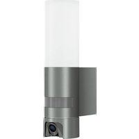
| Product type | Motion detector light (HF) |
| Brand | Steinel |
| Model | RS 20 S |
| Dimensions (Ø x D) | 280 x 110 mm |
| Power supply | 220-240 V, 50/60 Hz |
| Power consumption | 9.40 W |
| Standby power | 0.50 W |
| Detection technology | Hyperfrequency (HF) 5.8 GHz |
| Detection angle | 360° with 160° aperture |
| Range | 1 to 8 m (adjustable) |
| Time delay | 5 s to 15 min (adjustable) |
| Trigger threshold (lux) | 2 to 2000 lx (adjustable) |
| Orientation light function | Yes (10% power, adjustable 10/30 min or permanent) |
| Luminous flux | 942 lm |
| Color temperature | 3000 K (warm white) |
| Color rendering index (CRI) | Ra = 82 |
| Lifespan (L70B50 at 25°C) | 60,000 h |
| Protection rating (IP) | IP44 |
| Protection class | II |
| Diffuser material | PMMA |
| Operating temperature | -10 to +40 °C |
| Manufacturer warranty | 3 years |
| Repairability | Non-replaceable light source; repairs by specialized workshops |
| Maintenance | Clean with a damp cloth (without detergent) |
Frequently Asked Questions - RS 20 S STEINEL
Ceiling mounting is not suitable for exposed cables. Refer to the installation diagram in the manual.
c: permanent orientation light (on)
Off: off
10 min: orientation light for 10 minutes
30 min: orientation light for 30 minutes. The orientation light illuminates at 10% power.
User questions about RS 20 S STEINEL
0 question about this device. Answer the ones you know or ask your own.
Ask a new question about this device
Download the instructions for your Lamp in PDF format for free! Find your manual RS 20 S - STEINEL and take your electronic device back in hand. On this page are published all the documents necessary for the use of your device. RS 20 S by STEINEL.
USER MANUAL RS 20 S STEINEL
Please read carefully and keep in a safe place.
- Under copyright. Reproduction either in whole or in part only with our consent.
- Subject to change in the interest of technical progress.
Symbols

Hazard warning!

Reference to other information in the document.
2. General safety precautions

Disconnect the power supply before attempting any work on the unit.
- During installation, the electric power cable being connected must not be live. Therefore, switch off the power first and use a voltage tester to make sure the wiring is off-circuit.
- Installing the sensor-switched light involves work on the mains supply voltage.
This work must therefore be carried out professionally in accordance with national wiring regulations and electrical operating conditions. (e.g. DE-VDE 0100, AT-OVE / ONORM E8001-1, CH-SEV 1000)
- Only use genuine replacement parts.
- Repairs may only be made by specialist workshops.
3. RS 20 S
Proper use
- Sensor-switched wall/ceiling light with active motion detector. Limited suitability for outdoor use as a result of detection sensitivity
The integrated HF sensor emits high-frequency electromagnetic waves (5.8 GHz) and receives their echo. The change in echo caused by the slightest movement within the detection zone of the light is detected by the sensor. A microprocessor then issues the switch command "switch light ON". Detection is possible through doors, panes of glass or thin walls.
Note:
The high-frequency power of the HF sensor is approximately 1mW - 1000 times less than the transmission power of a mobile phone or microwave oven.
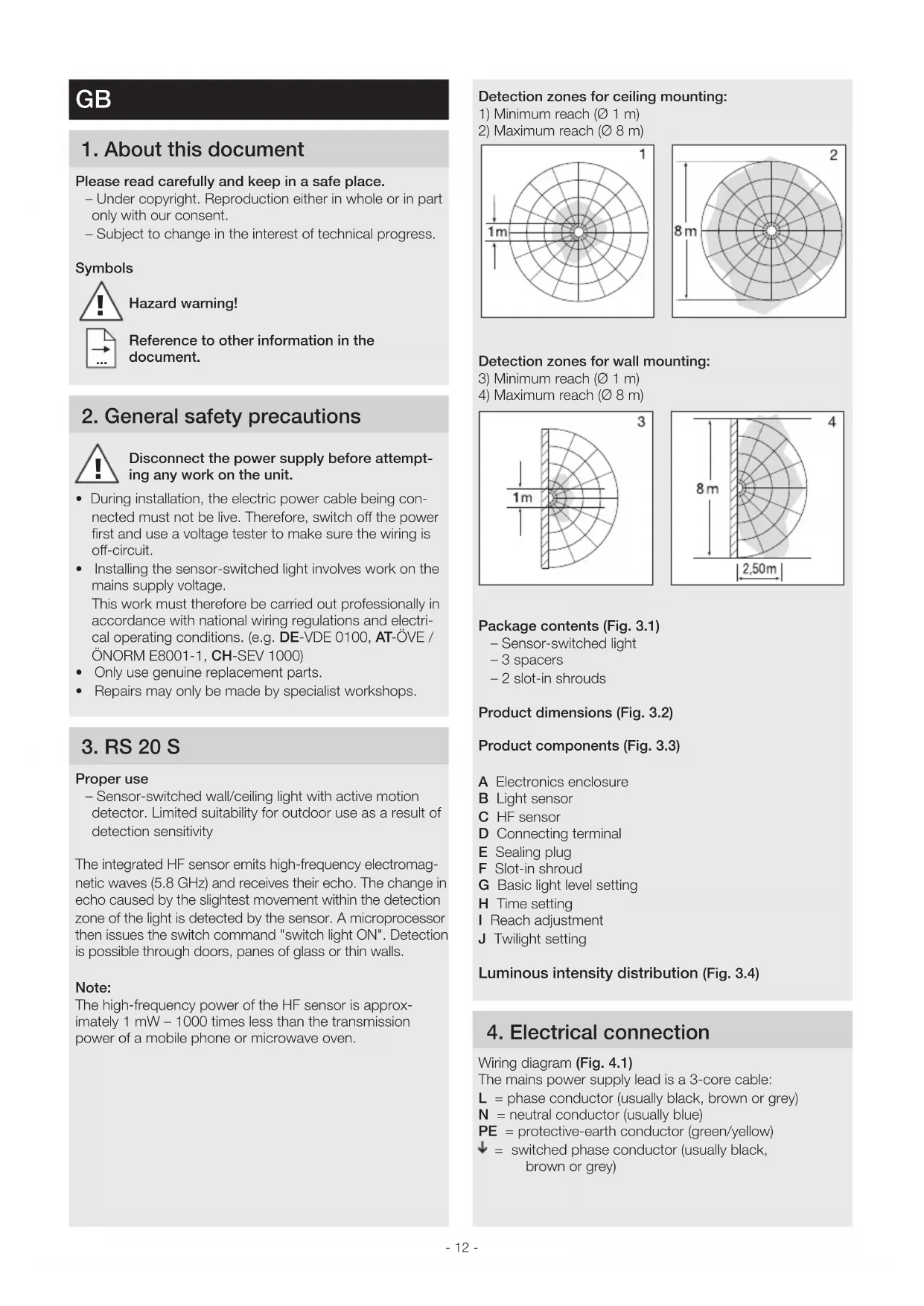
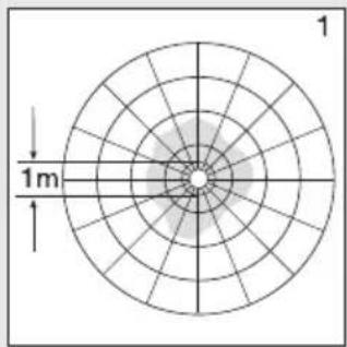
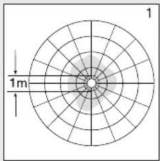
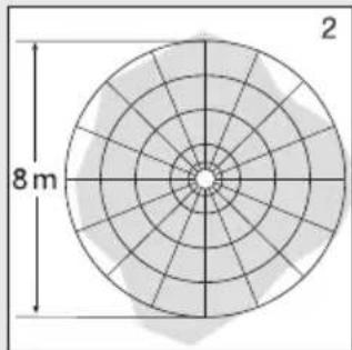
Detection zones for ceiling mounting:
1) Minimum reach ( - 1m)
2) Maximum reach ( 8m)
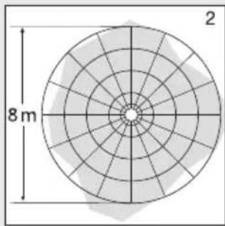
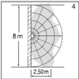
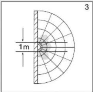
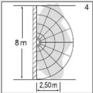
Detection zones for wall mounting:
3) Minimum reach ( 1m)
4) Maximum reach (0 8 m)
Package contents (Fig. 3.1)
- Sensor-switched light
- 3 spacers
-2 slot-in shrouds
Product dimensions (Fig. 3.2)
Product components (Fig. 3.3)
A Electronics enclosure
B Light sensor
C HF sensor
D Connecting terminal
E Sealing plug
F Slot-in shroud
G Basic light level setting
H Time setting
Reach adjustment
J Twilight setting
Luminous intensity distribution (Fig. 3.4)
4. Electrical connection
Wiring diagram (Fig. 4.1)
The mains power supply lead is a 3-core cable:
L = phase conductor (usually black, brown or grey)
N = neutral conductor (usually blue)
PE = protective-earth conductor (green/yellow)
= switched phase conductor (usually black, brown or grey)
If you are in any doubt, identify the conductors using a voltage tester; then disconnect from the power supply again. Connect phase (L), (↓) as well as the neutral conductor (N) to the connecting terminal.
Important:
Incorrectly wired connections will produce a short circuit later on in the product or your fuse box. In this case, you must identify the individual conductors once again and reconnect them. A mains power switch for turning the unit ON and OFF may of course be installed in the mains supply lead (in applications without emergency light module).
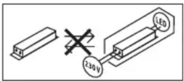
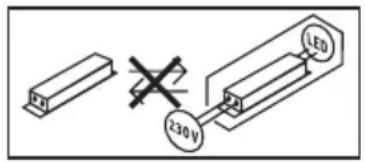
Connection to a dimmer will result in damage to the sensor-switched light.
Note:
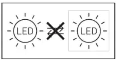
Do not make direct contact with the LED.
Note: The light source in this light cannot be replaced. If the light source needs to be replaced (e.g. at the end of its service life), the complete light must be replaced.
5. Mounting
- Check all components for damage.
- Do not use the product if it is damaged.
- When installing the sensor-switched light, make sure the installation site is not exposed to vibration.
- Select an appropriate mounting location, taking the reach and motion detection into consideration.
- Not suitable for ceiling mounting with surface-mounted power supply lead. (Fig. 5.1)
Installation procedure
- Switch OFF power supply (Fig. 4.1).
- Detach shade from enclosure (Fig. 5.2).
Mark drill holes (Fig. 5.3). - Drill holes and insert wall plugs (Fig. 5.4).
- Pierce sealing plug for power supply lead (Fig. 5.5)
- Installation with concealed power supply lead (Fig. 5.6).
- Installation with surface-mounted power supply lead (Fig. 5.7).
- Connect conductors (Fig. 5.8)
- Switch ON power supply (Fig. 5.9).
- Make settings "6. Function".
- Fit shade (Fig. 5.9).
6. Function
Factory settings
Twilight setting 2,000 lux
-Reach setting 8m
- Time setting 5 seconds
- Basic light level function Off
The sensor-switched light can be put into service after mounting the enclosure and connecting to the mains power supply. When putting the light into operation manually at the light switch, it will switch OFF after 10 seconds for the calibration phase and is then activated for sensor mode. It is not necessary to operate the light switch a second time.
Control dials (Fig. 6.2)
Twilight setting (response threshold) (J)
The chosen response threshold can be infinitely varied from approx. 2 to 2,000 lux.
- Control dial set to + = daylight mode (depending on ambient brightness)
- Control dial set to = twilight mode (approx. 2 lux)
The control dial must be turned to + when adjusting the detection zone and performing the functional test in daylight.
Reach setting (sensitivity) (I)
Reach is the term used to describe the diameter of the more or less circular detection zone produced on the ground after mounting the sensor-switched light at a height of 2.5m .
- Control dial + = max. reach of 8 m
- Control dial = min. reach of 1 m
Time setting (stay-ON time) (H)
The light's ON time can be set to any period from approx. 5 seconds to a maximum of 15 minutes. Any movement detected before this time elapses will restart the timer.
- Control dial set to + = longest time,approx. 15 minutes
- Control dial set to = approx. 5 seconds
Note:
After the light switches OFF, it takes approx. 1 second before it is able to start detecting movement again. The light will only switch ON in response to movement once this period has elapsed.
The shortest time setting is recommended when adjusting the detection zone and performing the functional test.
Basic light level function (G)
The basic light level function provides illumination at approx. 10% light output when the brightness setting is reached. Movement in the detection zone switches the light ON at 100% brightness for the time selected. Light switches OFF completely after the selected time has elapsed. If the brightness setting has not yet been reached, basic light is switched back ON again.
- Control dial set to = basic light ON
- Control dial set to Off = basic light OFF
- Control dial set to 10min = basic light for 10 minutes
- Control dial set to 30min = basic light for 30 minutes
Basic light is ON when the level of light falls below the brightness threshold. Basic light is always ON when daylight mode is activated. Basic light switches OFF every hour to measure ambient brightness. Basic light switches back ON again after a short period.
Manual override function
If an optional mains switch is installed in the mains supply lead, the following functions are available in addition to simply switching light ON and OFF:
Manual override (Fig. 6.3)
1) Activate manual override:
Switch OFF and ON twice. The light is set to manual override for 4 hours. Then it returns automatically to sensor mode.
2) Deactivate manual override:
Switch OFF and ON once. Light goes out or switches to sensor operation.
Important:
Switching must take place within 0.2 to 1 second.
You can reduce reach in four directions by fitting the slot-in shrouds included. (Fig. 6.4)
7. Maintenance and care
The product requires no maintenance.
The luminaire can be cleaned with a damp cloth (without detergents) if dirty.
The emergency light luminaire must be serviced at regular intervals in line with national regulations.
Important note: The control gear cannot be replaced.
8. Disposal
Electrical and electronic equipment, accessories and packaging must be recycled in an environmentally compatible manner.

Do not dispose of electrical and electronic equipment as domestic waste.
EU countries only:
Under the current European Directive on Waste Electrical and Electronic Equipment and its implementation in national law, electrical and electronic equipment no longer suitable for use must be collected separately and recycled in an environmentally compatible manner.

Do not throw devices, rechargeable batteries / batteries into household waste, fire or water at the end of their useful life. Rechargeable batteries /
batteries should be collected, recycled or disposed of in an environmentally friendly manner.
For EU countries only:
In accordance with Directive 2006/66/EC, defective or spent rechargeable batteries / batteries must be recycled. Waste rechargeable / non-rechargeable batteries can be returned to the point of purchase or to a collection facility for hazardous substances.
9. Manufacturer's warranty
Manufacturer's warranty of STEINEL GmbH, Diesel strasse 80-84, DE-33442 Herzebrock-Clarholz, Germany
All STEINEL products meet the highest quality standards. For this reason, we, the manufacturer, are pleased to provide you, the consumer, with a warranty under the following terms and conditions:
The warranty covers the absence of deficiencies which are proven to be the result of a material defect or fault in manufacturing and which are reported to us immediately after detection and within the warranty period. The warranty shall apply to all STEINEL products sold and used in Germany - excluding STEINEL Professional products.
You can opt for warranty cover in the form of repair or replacement which will be provided free of charge (if applicable, in the form of a successor model of the same or higher quality) or in the form of a credit note.
The warranty period for the STEINEL product you have purchased is 3 years (5 years for products from the XLED home range) in each case from the date on which the product was purchased.
We shall bear the shipping costs but not the transport risks involved in return shipment.
Statutory rights accruing from defects, gratuitousness
The warranty cover described here shall be applicable in addition to the statutory rights of warranty - including special consumer protection provisions - and shall not restrict or replace them. Exercising your statutory rights in the event of defects is gratuitous.
Exemptions from the warranty
All replaceable lamps are expressly excluded from this warranty. In addition to this, the warranty shall not cover:
any wear resulting from use or any other natural wear of product parts or any deficiencies in the STEINEL product that are attributable to wear caused by use or other natural wear.
-any improper or non-intended use of the product or any failure to observe the operating instructions,
any unauthorised additions, alterations or other modifications to the product or any deficiencies attributable to the use of accessory.
-supplementary or replacement parts which are not genuine STEINEL parts,
-any maintenance or care of products that is not carried out in accordance with the operating instructions,
-any attachment or installation that is not in accordance with STEINEL's installation instructions,
- any damage or loss occurring in transit.
Application of German law
The warranty shall be governed by German law excluding the United Nations Convention concerning the International Sale of Goods (CISG).
Making claims
If you wish to make a warranty claim, please send your product complete and carriage paid with the original receipt of purchase, which must show the date of purchase and product designation, either to your retailer or directly to us at STEINEL (UK) Ltd. - 25 Manasty Road, Axis Park, Orton Southgate, GB- Peterborough Cambs PE2 6UP United Kingdom.
For this reason, we recommend that you keep your receipt of purchase in a safe place until the warranty period expires.

10. Declaration of Conformity
Hereby, STEINEL GmbH declares that the radio equipment type RS 20 S is in compliance with Directive 2014/53/EU. The full text of the EU declaration of conformity is available at the following internet address: www.steinel.de
11. Technical specifications
| Dimensions (Ø x D) Ø 280 x 110 mm | |
| Supply voltage 220-240 V, 50/60 Hz | |
| Material PMMA (shade) | |
| Power consumption (Pon) 9.40 W | |
| Standby sensor (Psb) 0.50 | |
| Mains current 230 V - 45 mA | |
| Power factor 0.91 | |
| Additional switching capacities Filament bulb/halogen load 800 W | |
| Fluorescent lamp electronic ballasts 250 W | |
| Fluorescent lamps, uncorrected 400 VA | |
| Fluorescent lamps, series-corrected 400 VA | |
| Fluorescent lamps, parallel-corrected 400 VA | |
| Low-voltage halogen 800 VA | |
| LED < 2 W | 100 W |
| 2 W < LED < 8 W | 125 W |
| LED > 8 W | 250 W |
| Capacitive load | 88 μF |
| Luminous flux (360°) | 942 lm |
| Efficiency | 100 lm/W |
| Colour temperature | 3,000 K (warm white = WW) |
| Colour rendering index R | a = 82 |
| Average rated life expectancy | L70B50 at 25°C: 60,000 hours |
| Colour consistency SDCM | SDCM 3 |
| Luminous intensity distribution | |
| HF technology | 5.8 GHz (responds to the slightest movement regardless of temperature) |
| Angle of coverage | 360° with 160° angle of aperture |
| Transmitter power | approx. 1 mW |
| Reach | 1-8 m |
| Time setting | 5 s-15 min |
| Basic light level | 10% |
| Twilight setting | 2-2,000 lux |
| IP rating | IP 44 |
| Protection class | II |
| Temperature range | -10 to +40°C |
| Energy efficiency class | This product contains an energy efficiency class "E" light source. |
12. Troubleshooting
GB
| Malfunction Cause Remedy | ||
| Sensor-switched light without power | ■ Fuse has tripped, not switched ON, break in wiring | ■ Activate, change fuse, turn ON mains switch, check wiring with voltage tester |
| ■ Short circuit in mains power supply lead | ■ Check connections | |
| ■ Any mains switch OFF | ■ Switch on mains switch | |
| Sensor-switched light will not switch ON | ■ Wrong twilight setting selected | ■ Reset |
| ■ Mains switch OFF | ■ Switch ON | |
| ■ Fuse has tripped | ■ Activate, change fuse, check connection if necessary | |
| Sensor-switched light will not switch OFF | ■ Continued movement within the detection zone | ■ Check detection zone |
| Sensor-switched light switches ON without any identifiable movement | ■ Light not mounted for detecting movement reliably | ■ Securely mount enclosure |
| ■ Movement occurred, but not identified by the observer (movement behind wall, movement of a small object in immediate lamp vicinity etc.) | ■ Check detection zone | |
| Sensor-switched light does not switch ON despite movement | ■ To minimise malfunctioning, rapid movements are suppressed or detection zone too small | ■ Check detection zone |
| ■ Wrong twilight setting selected | ■ Reset | |
FR
3 ARS PRODUCENT GARANTI
10. Overensstemmelseserklaering
Hermed erklaerer STEINEL GmbH, at radioudstyrsypen RS 20 S er i overensstemmelse med direktiv 2014/53/EU. EU-overensstemmelseserklaeringens fulde tekst kan findes pa ffolgende internetadresse: www.steinel.de
11. Tekniske data
| Mål (Ø × D) Ø 280 × 110 mm | |
| Netspaending 220–240 V, 50/60 Hz | |
| Materiale PMMA (skærm) | |
| Effektforbrug (Pon) 9,40 W | |
| Standby sensor (Psb) 0,50 | |
| Netstrom 230 V - 45 mA | |
| Effektfaktor 0,91 | |
| Øvridge effekte Glode-/halogenpær | ast 800 W Lysstofrølektr. forkobl.enh. 250 W Lysstofrøukompenseret 400 VA Lysstofrøseriekompenseret 400 VA Lysstofrøparallekompenseret 400 VA Lavspaendings-halogenpærer 800 VA LED < 2 W 100 W 2 W < LED < 8 W 125 W LED > 8 W 250 W Kapacitiv belastning 88 μF |
| Lysstrøm (360°) | 942 lm |
| Effektivitet | 100 lm/W |
| Farvetemperatur | 3.000 K (varm hvid = WW) |
| Farvegengivelsensindeks | Ra=82 |
| Gennensnitig beregnet levetid | L70B50 ved 25 °C: 60.000 timer |
| Farvekonsistens SDCM | SDCM 3 |
| Lysstyrkeforderding | |
| HF-teknochogi | 5,8 GHz (reagerer på selv små bevægelser uafhængigt af temperatur) |
| Overvågningsvinkel | 360° med 160° Åbningsvinkel |
| Sendeeffekt | Ca. 1 mW |
| Rækkevidde | 1–8 m |
| Tidsindstilling | 5 s–15 min |
| Grundlys | 10 % |
| Skumringsinndilling | 2–2.000 lux |
| Kapslingsklasse | IP 44 |
| Beskyttelsesklasse | II |
| Temperaturområde | -10 til +40°C |
| Energieeffektivitetsklasse | Dette produit indeholder en lyskilde i energieffektivetsklasse „E". |
Stillskrue (ill. 6.2)
Skumringsinnstilling (reaksjonsivá) (J)
Permanent lys (ill. 6.3)
1) Tenne permanent lys:
3 Y I L U R E T I C I G A RANTISI
10. Uygunluk beyani
3 ANI GARANTIA PRODUCTORULU
10. Declaratie de conformitate
HactpoKa Ha CBetNoyBCTBNTenHOcTTa (npar Ha 3aeneCTBaHe) (J)
KeJahnT npar Ha 3aDenCTBaHe Ha lamnata MoKe da 6bJe peRyInpan 6e3TeenHNO OT OKoNo 2 Do 2.000 lykca.
- Perynatop B no3nua + = HeBeH peKIM (He3aBncmoOTOCBETeHOCTTa)
- Perynatop B no3nua - = cna6a cbettnHa (okono 2 nyka)
Pn HacpoKa Ha 0xbata n np npOBepKa Ha yHKunTe Ha DHeBHa CBetTInHa peryNaTOpbT Tp6Ba Da e Ha +.
HacpoKa Ha 06Xbata (yBCTBnTeJIHOcT) (I)
NoHrTneTo 06XbAT Bn3npa DnAmEtBpa Ha npu6Iin3nteHNO KpbJlata O6NaCT Ha nOda, KOrTO ce o6pa3yBa npN MoTHaK Ha BnCOUHa 2,5 M.
- PerynaTop + = MaKcImMaJIeH 06XbaT 8 M
- Perynatop - = MHHMaJIeH 0xbaT 1 M
Hactpoika Ha BpeMeTo (BpeMe Ha DonbJIHHTeHOnOcBeTBAHe) (H)
XeHaHATA npoBnJxNtEnHO t cBeTeHe Ha JAmnata MoKe da ce perynipa 6e3TeNeHHO OTKOLO 5 cekHyDIO MaKc. 15 MInyTu. BcKaO 3aceHo DvNxKeHne IpeDn N3TuHa He BaPemTo BpBua YacOBHnKa B nbpBOHaunHa No3uIyra.
- Perynatop + = OKOIO 15 MInHyTN
- Perynatop = okono 5 cekydn
CbeHeHne:
CneB BcAko N3KJIIOUBaHe Ha NaMnTa 3acuHaTeHO HOBN DnBXKeHnCe npeKbCBA 3a OKo1 OceHyda. EDbacNeT TOBa JAmNaTa MOKe Da Ce BKJIIOH npi 3aceeHo DnBXKeHnE.
Pn HacpoKa Ha 0xbaTa n 3a npOBepKa Ha fynKunTe ce npenopbUba Da 6bJe N36paH Han KpaTkna INTEpBaJ.
Yka3aHHe:MoUHocTbB4-ceHCopa coCTabnEeK.1MBT -3TO BCEO JINMb ODA TbICRHaHAR MOUHOCTN, N3NYaEMOM COTOBbIM TENEFOHOM INMNI MKNPOBOJHOBOI NeybIO.
3oHa 6hApxHnI npMOnTaxKe Ha IIOToJIke:
1)MHHIMaJIbHbIpaNycDeiCTBn(01M)
2) MaKcImMaJIbHbI paIuYc DeIcTBn (Ø 8 M)
30ha 6hApxHn np MoTaxHe Ha cTeHe:
3) MHHIMaJIbHbI paIynyc DeiCtBnI (0 1 M)
4) MaKcImMaJIbHbI paDnyc DeIcTbIa (Ø 8 M)
KOMNJIeKT NOCTABKN (pnc. 3.1)
- CeHCOPHbI CBETNJbHNK
-3npocTaBKN
-2BCTaBHbIe3acJIOHKn
Pa3MepbI m3dennr (pnc. 3.2)
0630pycTpoiCTBa(pnc.3.3)
A BLOK 3neKTpoHnki
B CBeTOBOeHcOp
C BY-ДТУК
D KneMa nOdkNIOueHn
E ynnOTHTeIb
F BctaBHa nHaHeNb
G YctaHOBka 6a3OBOI npKoCTN
H BpemBkJHOeHHN
YCTAHOBKa dAJIbHOCTN DeIcTBNIA
J YcTaHOBKa CymepeHOrO BKNIOueHnA
PacnpepeHne cunblcBeta (pnc.3.4)
4.Злектуескoe поdkючене
- YCTaHOBOUHbI peYJrTOp + = MaKc. paDnyc DeiCTBn8M
- YctaHOBOUHbI peYJrTOp - = MInH. paDnyc DeNCTBn1M
Bpem BkHueHnBpem octatoHoro BKIOeHn (H)
Heo6xOJIMoe Bpem OCBeUeHn MOKeT 6bItb yCTaHOJIeHO Ha CBtUNbHKe PNaBHO B DnAna3OHe OT 5 cK. Do MaKc.15 MIn. KaXIOe 3aperNCTpnpOBaHHoe DINXKeHne IIO NCTeHn 3TOI BpEmHn 3aHOBO HauHHaET OTCHT BpEmHn.
- YctaHOBOHbIpeRyJrTOpHa+ =OK.15MH
- YctaHOBOHbI peYJrTOp - = OK. 5 cek.
Yka3aHHe: NocJe KaKDoR npOuecca OTKIOUeHn CBeTINbHnKa 6hApuyKeHne HOBO nBnXeHn IpepbBaetcnpM. Ha 1 cekyHny. Tolbko no nCTeHnn 3TOrO BpemeHnCBETINbHnK MOKeT CHOBA BKNIOuHaTB CBET npDnBIXeHn.
Pn yctaHOBKe 30HbI o6hApyKeHn I npn npoBeHn 3KcNJIyataUIOHHOrTo Tecta peKOMeHnyeTcR yCTaHaBnIBaTb Han6Oone KOpOTKe Bpemr.
Функцьба30BOBJRPKOCTN(G)
Функляба30BOJЯрКОТи OБсЕЧИВАЕСOBSEHNE MOUHOCTBIO OK.10%,KOrda IOCTNRAETCЯ YCTaHOBJIENHOO 3HAueHne OCBeUeHHOCTn.IpNi DBuXKeHIM B 3OHe O6HaPyxKeHIN CBET BKIIQUAeTcHa YCTaHOBJIENHoe BpeM.
Пи ДвnxнгИВ 3Он eOBHApxKeHn CBET BKJIOHaTcHa YcTaHOBJIeHHoe BpEm CypOBHeM OCBeUeHHoCTn 100%.
No nCTeEHn yCTaHOBJEHHORo BpEmeHN BKJIOueHn CBET NOJIHOCTbIO BbIKJIOHaETc. EcIn yCTaHOBJeHHoe 3HaueHne OCBeIeHHOCTn BCE eIe He IOCTnIgAETc, TO 6a3OBa IRPKoCTb CHOBA BKJIOHuaTc.
- PerynTop Ha = 6 a3oBa npKocTb BKJI.
- PerjTOp Ha Off = 6a3oBaar npKocTB BblKJI.
- PerynarTop Ha 10 MNH. = 6a3oBa rpkocTb 10 MNH.
- Perjntop Ha 30 MNH. = 6a3oBa JpKocTb 30 MNH.
Ba3OBa yapKocb BKJ, ecn ypoBHe onyckaetc HnKe npAknBupoBaHHom pexime nHEBHOOCBeUeHn6Ba3OBa yapKocb Bcerda BKJ. Ba3OBa npKocb BblKnIOuaeTc KaXdbI qac, YTO6bl N3MepuTB INTEHCMBOCTCBcTa OKpyKeHn. No nCTeueHm KOpOTKOBOBpeMeHN Ba3OBa npKocb CHOBA BKJIIOHaetc.
NoctoHHoe OcBeueHne
B cIyueoIohbHou yCTaHOBKn CeTeBOr BO BIKIOUOaTeJI B CTeBOI POBOD, NOMMO 6a3OBx CyHKUN BKJIO-HeHH N BIKIOUeHEN CBETA Iprn DnBnKeHN IOCTYINHbI DOCTynHbI CNeDyUOuE CyHKUN:
PeknIOCTOHHOROCBeHn (pnc.6.3)
1) BkIoueHne NOCToHHoro OcBeueHnra: BblKIOuHaTeNb 2x BblKJI. n BkJI. CBeTINbHnK Ha 4 yaca yctaHaBnBaETcRa HnOCToHHbI CBET. IIO nCTeHeHn BpEmEH npOn3BOJNTcA aBTOMaTHHeCKoe nepeKIOUeHne B ceHCOPHbI peKIM.
2) BbIKIOueHne nocToHHoro ocBeueHn: BblKIOaTenb 1x BblKN. n BKN. CBeTNbHNk BblKIOHaeTCra NnI nepeKIOUaETcB CeHCOPHbI pEXIM.
BaxHo:
IpoueccbI nepeKIOUeHn IOnKHBi BbINONHrTbcR B Dnana-30He ot 0,2 do 1 cekyHbI.
3a cHT yCTAHOBKn npNJaraembIX 3acNOHOK MOXHO yMeHbWNTb paNyc DeNCTBnB YcTbIPex HAnpaBHeHnx.
(pnc.6.4)
7. Texnueckoe 6cnykBaHne u xoD
IpoDyKT He Tpe6yeT TexHnueckoro 06cIyKnBaHna.
3aarpzHeHnHa CBeTbHKe MOxHO ydaJIbTB BnaXHbIM cyKHOM (HE NCNoJb3y MOUcne CpeICTBa).
CBeTINbHnK abapnHoro oCeEHHa DOJIKeH npoxOHTb peryIrpHoe TexHueckoe 0cCnykBaHne cOnlaCHO HauNoHaJIbHbIM PpeDnucHnM.
BaxHo:Pa6ooye H3JeJIne 3aMeHHTb HeIb3r.
8. Ytvn3aun
3NeKtpponp6opbl, KOMNJIeKTKUOJIne n ynaKOBky cJIeNyET HAnpaBJIaTb Ha 3KOLOrHHyIO BTOpHHyIO nepepa6oTKy.

He BbIbpaBbBaTb 3JIeKTpOpiN6OpbI B 6bITOBbie OTXoDbI!
TolbokdIaCTpaH EC:
Corgnacno Deicbtyuoue EBponecko nIpeKtNBIO Otpa6oTaHHOMy 3neKTpHecCKOMy N 3neKTPOHOMy 06OppyoBaHIO u ee pealnaunB HauNoHaBbIX 3aKOHOdaTeJIbCTbAX OTPa6oTaHHbIe 3neKTponpnpOpbl DOJXHbIco6npaTbcra OTdJIbHO N HaipabJIaTbcra Ha 3KOLOHHyOBTOPIHHy IOpepa6Oly.

He Bb6paacbIbTaB Otpa6oTAbUHne yctpoiCTBa, aKkymyIaTOpbl/6aTapeu BMecTe C 6blTOBbIMN OTXOaAMN, B OOrH NIN B BODY. AkkymyIaTOpbl/
6aTapeH HeoXOJIMO CObnpaTb,OTnPaBJIaTb Ha BToPnHyIO nepepaOToKy IIN yTInN3OBaTb 3KOJOnuHbIM CnOCo6om.
TolbokdnyctpaH EC:
Cornacho DnpeKtBRe RL 2006/66/EG HeucnpaBbIe nIOTpa6oTbUHe aKKymJrToPbI/6aTapeN DoJIckHbI OTpabJIraTbCnHa BTOpUHyIO nepepa6Oky. He npiroDhIE nIACNOJB3OBaHnA aKKymJrToPbI/6aTapeN MOxHO CdaTbMara3IN NII IN BpyHKT PnEema ONaChbIX OTXODOB.
9. Гаши рponьдпеля
TapaHTna npOn3BODnteA STEINEL GmbH, Dieselstraße 80-84, DE-33442 Herzebrock-Clarholz, TepMaHnia
DaHHoe n3dJIe npoINBODCTBa Steinel 6bIIO COCOBIM BHIMAHmE m3rTOBJIeHO NcNbITaHO Ha pa6OTOCNO6HOCTb N6e3OJaCHOCTb kCkTIyAtauM COOTBETCTBEHNO DeiCTByIOUIM INCHpyKUJAM, a NOTOM NOdBepHyTO BbIOPOOHMy KOHTPONIO KauEcTba.
ФирмASTEINEL rapaHTnpyet BbICOKOE KaHecTBO nHa-
dExHyopapObyu3dEnyra. TapaHTnHbI cPOK 3KcNnyataa
UcoCTABnREt 36 MeCAeB CO DnH npOdaXn u3dEnyra.
FInpMa O63yETcYcTpaHnTB HeoCTaTKn, KOToPbIE BO3-
HNKn BCNEcCTBne DepekTa MaTePnAa NIN KOHCTpyKuMn.
DepeKbI yCTpaHnIOr cnyEm pemOHTa u3dEnyra JIo60
3aMeHO HncCnpabHBx DeTaneN NO YCMOTpeHnIO PhnPmbl.
TapaHTnHbI cPCK 3KcNnyatauNn He pacnpocTpaHreTc
Ha NoBpeKdEny n DepeKbI, BO3HKnWne B pe3yNbTaTe
u3HOca DeTaneN, HeNaLKeKaUe N KcNnyatauN n yXoJa.
PhiMa He Hecet OTBeTcBEHoHOctN 3a MaTePnaHBn
yUep6 TpeTbNx NII, HaHeceHHbN B ProUceCE 3KcNnyatauN
u3dEnyra. TapaHTn PpeOCTaBnErc TOnbKO B TOM
Clyue, ecn u3dEnne B Co6paHHOM n YNAKObaHHom Bunde C KpATKM ONCaHNeM HeNCpBaHOCt N bIIO OTnpaBHeHO
BMecTe C PrINOxoHbIM KACCOBbIM YeKOM UIN KBNTaHUNe (C dATO npOdaXn IN NeaTbTO TopROBO npeDnpaTn)
No aDpccy cepBnCHOn MaCTepckOn.
PemontbIcpeBnC:No nCTeHn rapaHTnHOrO cpoKa nn np HAnHn HnOlaDOK, NCKIOUaIOUXrapaHTNIO, o6paTntecb B 6JnxKaIuee cepBnCHoe ppeINprrTne, TTo-6blnoJyHTb INHOpMaUIO O BO3MOXHOCTn peMOHTa.

10. CeptnФнкat COOTBETCTBnA
HactoIIM KOMnAHH STEINEL GmbH 3aBnEeT,TO pa- IIOaIIapatypa Tnra RS 20 S OTeyaeT
Tpe6oBaHnIaM DpuKeTnBbl 2014/53/EU. IOnHbI TeKCT cePTnDfNkata COOTBeTCTBna EC DoCTyneH No CNeDuOeMy aDpeCy B INHTepHete: www.steinel.de
11. TexHHueckne daHHbIe

- Please read carefully and keep in a safe place.
- Symbols
- General safety precautions
- Disconnect the power supply before attempting any work on the unit.
- RS 20 S
- Proper use
- Note:
- Detection zones for ceiling mounting:
- Detection zones for wall mounting:
- Package contents (Fig. 3.1)
- Product dimensions (Fig. 3.2)
- Product components (Fig. 3.3)
- Luminous intensity distribution (Fig. 3.4)
- Electrical connection
- Wiring diagram (Fig. 4.1)
- Important:
- Mounting
- Installation procedure
- Function
- Factory settings
- Control dials (Fig. 6.2)
- Twilight setting (response threshold) (J)
- Reach setting (sensitivity) (I)
- Time setting (stay-ON time) (H)
- Basic light level function (G)
- Manual override function
- Manual override (Fig. 6.3)
- 1) Activate manual override:
- 2) Deactivate manual override:
- Maintenance and care
- Disposal
- EU countries only:
- For EU countries only:
- Manufacturer's warranty
- Statutory rights accruing from defects, gratuitousness
- Exemptions from the warranty
- Application of German law
- Making claims
- Declaration of Conformity
- Technical specifications
- Troubleshooting
- FR
- Overensstemmelseserklaering
- Tekniske data
- Stillskrue (ill. 6.2)
- Skumringsinnstilling (reaksjonsivá) (J)
- Permanent lys (ill. 6.3)
- Uygunluk beyani
- Declaratie de conformitate
- HactpoKa Ha CBetNoyBCTBNTenHOcTTa (npar Ha 3aeneCTBaHe) (J)
- HacpoKa Ha 06Xbata (yBCTBnTeJIHOcT) (I)
- Hactpoika Ha BpeMeTo (BpeMe Ha DonbJIHHTeHOnOcBeTBAHe) (H)
- CbeHeHne:
- 3oHa 6hApxHnI npMOnTaxKe Ha IIOToJIke:
- 30ha 6hApxHn np MoTaxHe Ha cTeHe:
- KOMNJIeKT NOCTABKN (pnc. 3.1)
- Pa3MepbI m3dennr (pnc. 3.2)
- 0630pycTpoiCTBa(pnc.3.3)
- PacnpepeHne cunblcBeta (pnc.3.4)
- 4.Злектуескoe поdkючене
- Bpem BkHueHnBpem octatoHoro BKIOeHn (H)
- Функцьба30BOBJRPKOCTN(G)
- NoctoHHoe OcBeueHne
- PeknIOCTOHHOROCBeHn (pnc.6.3)
- BaxHo:
- Texnueckoe 6cnykBaHne u xoD
- Ytvn3aun
- TolbokdIaCTpaH EC:
- TolbokdnyctpaH EC:
- Гаши рponьдпеля
- CeptnФнкat COOTBETCTBnA
- TexHHueckne daHHbIe
Brand : STEINEL
Model : RS 20 S
Category : Lamp