
PC4 - Stapler STEINEL - Free user manual and instructions
Find the device manual for free PC4 STEINEL in PDF.
| Product type | DALI-2 push-button coupler |
| Brand | Steinel |
| Model | PC4 |
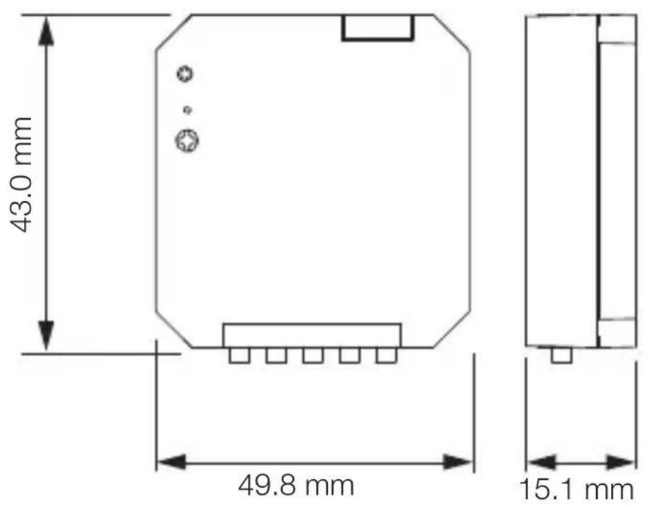
| Dimensions (H x W x D) | 49.8 x 43.0 x 15.1 mm |
| Voltage range | 9.5 VDC - 22.5 VDC |
| Typ. DALI supply (16.5 V) | 2.7 mA |
| Max. DALI supply (22.5 V) | 9 mA |
| DALI-2 addresses | 1 |
| Number of inputs | 4 |
| Input type | Potential-free push button/switch |
| Input terminal designations | K1, K2, K3, K4 |
| Max. housing temperature | 75 °C |
| Protection class | II |
| IP protection rating | IP20 |
| Ambient temperature | -20 °C to +50 °C |
| Max. coupler cable length | 50 m |
| Cleaning and maintenance | Clean only with a dry cloth. No maintenance required. |
| Manufacturer's warranty | 5 years for consumers and contractors (subject to conditions) |
| Compliance | Directive 2014/53/EU |
Frequently Asked Questions - PC4 STEINEL
User questions about PC4 STEINEL
0 question about this device. Answer the ones you know or ask your own.
Ask a new question about this device
Download the instructions for your Stapler in PDF format for free! Find your manual PC4 - STEINEL and take your electronic device back in hand. On this page are published all the documents necessary for the use of your device. PC4 by STEINEL.
USER MANUAL PC4 STEINEL
- About this document 21
- General safety precautions 21
- System description 22
- Electrical connection 26
- Installation 27
- Cleaning and maintenance 32
- Disposal 32
- Conformity 32
- Manufacturer's Warranty 33
- Technical specifications 36
- Troubleshooting 36
1. About this document
- Under copyright. Reproduction either in whole or in part only with our consent.
- Subject to change in the interest of technical progress.
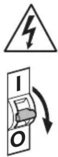
Hazard warning!
Warning of hazards from electricity!
2. General safety precautions

Failure to observe these operating instructions presents hazards!
These instructions contain important information on the safe use of this product. Particular attention is drawn to potential hazards. Failure to observe this information may lead to death or serious injuries.
- Read instructions carefully.
- Follow safety advice.
-
Keep instructions within easy reach.
-
Working with electrical current may produce hazardous situations. Touching live parts can result in electrical shock, burns or death.
- Work on mains voltage must only be performed by qualified, skilled personnel.
- National wiring regulations and electrical operating conditions must be observed (e.g. DE: VDE 0100, AT: ÖVE-ÖNORM E8001-1, CH: SEV 1000).
- Only use genuine replacement parts.
- Repairs must only be carried out by companies qualified to do so
3. System description
Proper use
- Interface for standard switches.
- Suitable for installation in a concealed box with a minimum depth of 60~mm .
Non-intended use
- The terminals on the switch coupler are not suitable for mains voltage.
Operating principle
- The switch coupler integrated additional switched into a DALI lighting system.
- Up to four standard switches can be connected to each switch coupler.
- The switch coupler relays the signals to the application controller (APC) / control unit via DALI.
- The switches can be programmed to function in any chosen way at the time they are put into operation.
3.1
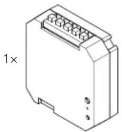
1x

1x
- 1 switch coupler
- 1 safety data sheet
- 1 quick-start guide
Product dimensions
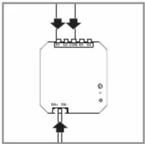
3.2
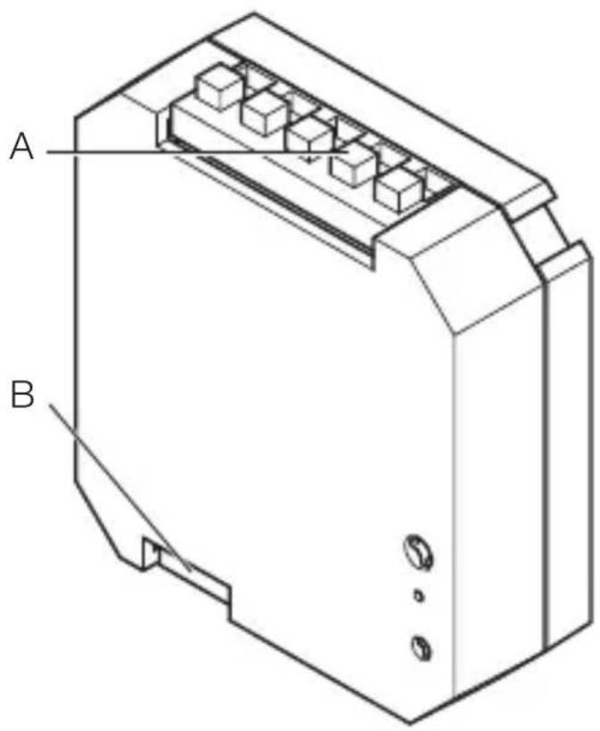
3.3
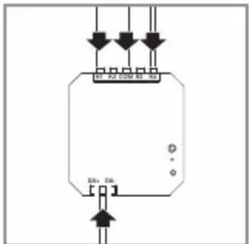
A Switch terminals
B DALI-2 input
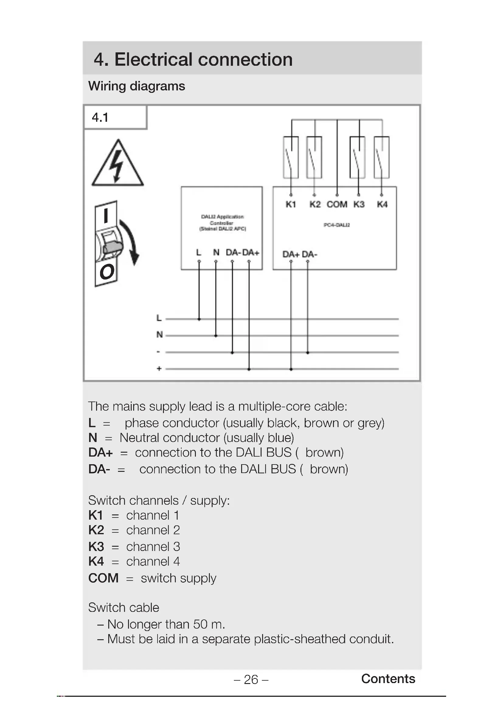
4. Electrical connection
Wiring diagrams
4.1
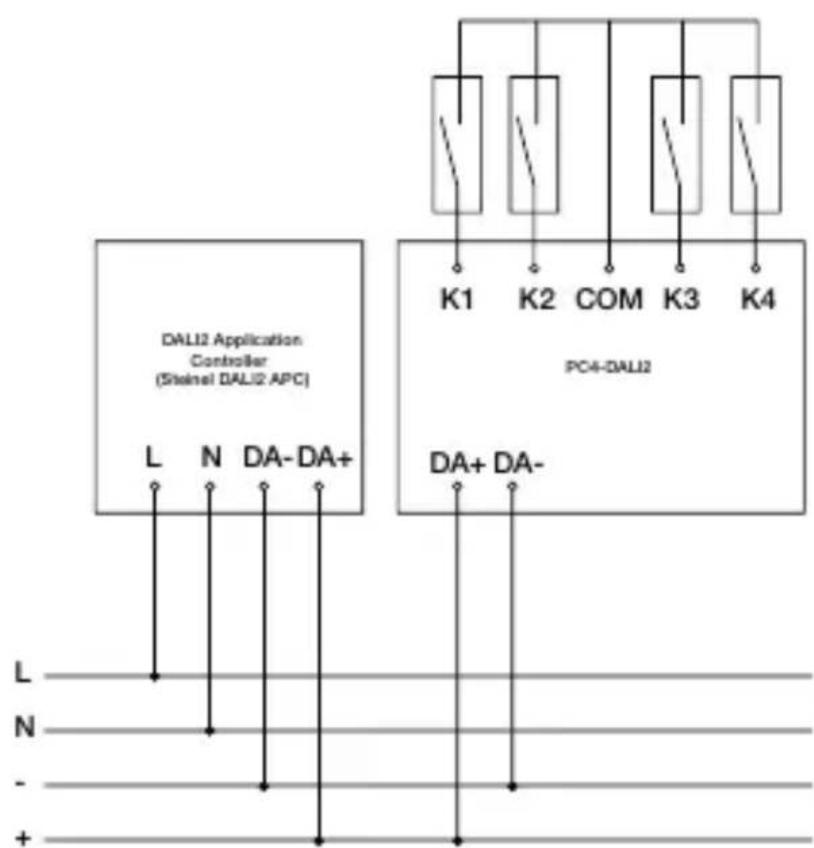
The mains supply lead is a multiple-core cable:
L = phase conductor (usually black, brown or grey)
N = Neutral conductor (usually blue)
DA+ = connection to the DALI BUS ( brown)
DA- = connection to the DALI BUS ( brown)
Switch channels / supply:
K1 = channel 1
K2 = channel 2
K3 = channel 3
K4 = channel 4
COM = switch supply
Switch cable
- No longer than 50 m .
- Must be laid in a separate plastic-sheathed conduit.
5. Installation

Hazard from electrical power.
Touching live parts can result in electrical shock, burns or death.
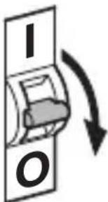
- Switch OFF power and interrupt power supply.
- Using a voltage tester, check to make sure that the power supply is disconnected.
- Make sure power supply remains interrupted.
Risk of damage to property!
Mixing up connection leads may produce a short circuit.
- Identify connection leads.
- Connect the leads correctly.
Preparing for installation
- Check all components for damage. Do not use the floodlight if it is damaged.
- Familiarise yourself with the fitting situation and the relevant documentation.
- Select an appropriate site to install the product.
-Vibration-free.
-Not in explosive atmospheres.
-Not on normally flammable surfaces.
5.1

- Put together the tools and material needed: -Screwdriver.
Installation procedure
Example application: 1 switches
5.2
- Make sure the power supply is switched OFF.
- Connect mains power supply lead as shown in the wiring diagram.
"4. Electrical connection"
Example application: 2 switches
5.3

- Make sure the power supply is switched OFF.
- Connect mains power supply lead as shown in the wiring diagram.
"4. Electrical connection"
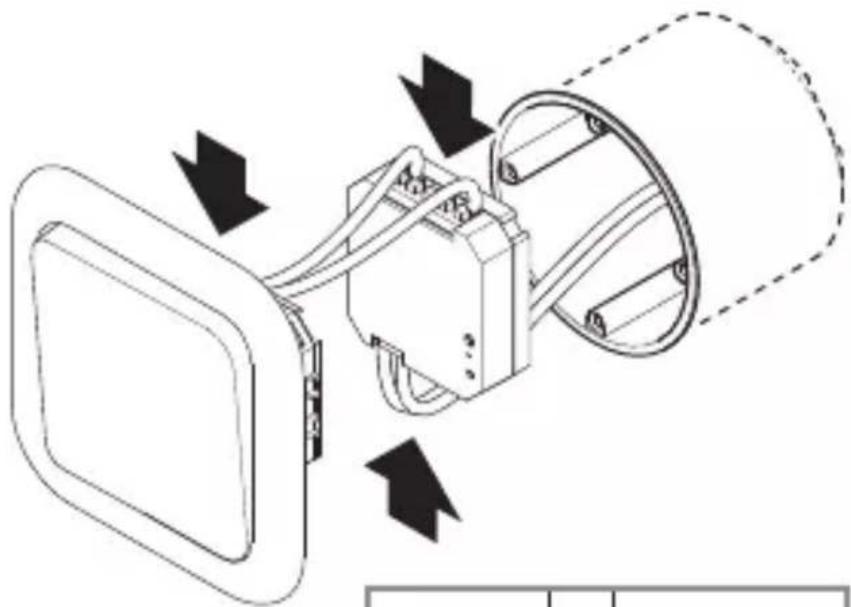
5.4
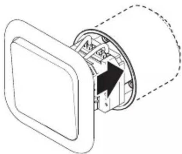
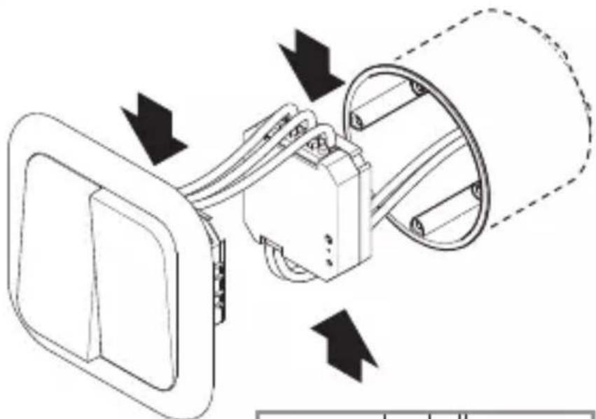
- Fit switch coupler into the box.
- Fit switch onto the box.
5.5

- Switch ON power supply.
GB
6. Cleaning and maintenance
The tool requires no maintenance.
Hazard from electrical power.
Contact between water and live parts can result in electric shock, burns or death.
- Only clean tool in a dry state.
7. Disposal
Electrical and electronic equipment, accessories and packaging must be recycled in an environmentally compatible manner.
Do not dispose of electrical and electronic equipment as domestic waste.
EU countries only:
Under the current European Directive on Waste Electrical and Electronic Equipment and its implementation in national law, electrical and electronic equipment no longer suitable for use must be collected separately and recycled in an environmentally compatible manner.
8. Conformity
STEINELGmbH hereby declares that the PC4-DALI-2 switch coupler radio equipment type conforms to Directive 2014/53/EU. The full wording of the EU Declaration of Conformity is available for downloading from the following Internet address: www.steinel.de
9. Manufacturer's Warranty
Manufacturer's warranty of STEINEL GmbH,
Diesel strasse 80-84, DE-33442 Herzebrock-Clarholz, Germany
All STEINEL products meet the highest quality standards.
For this reason, we, the manufacturer, are pleased to provide you, the customer, with a warranty under the following terms and conditions:
The warranty covers the absence of deficiencies which
are proven to be the result of a material defect or fault in manufacturing and which are reported to us immediately
after detection and within the warranty period. The warranty shall cover all STEINEL Professional products sold and used in Germany.
Our warranty cover for consumers
The provisions below apply to consumers. A consumer is any natural person who, on entering into the purchase transaction, neither acts in exercising their commercial nor their self-employed activity.
You can opt for warranty cover in the form of repair or replacement which will be provided free of charge (if applicable, in the form of a successor model of the same or higher quality) or in the form of a credit note.
In the case of sensors, floodlights, outdoor and indoor lights, the warranty period for the STEINEL Professional product you have purchased is 5 years in each case from the date on which the product was purchased.
We shall bear the shipping costs but not the transport risks involved in return shipment.
Our warranty cover for entrepreneurs
The provisions below apply to entrepreneurs. Entrepreneur is a natural or legal person or partnership with legal personality who or which, on entering into the purchase transaction, acts in exercising their or its commercial or self-employed activity.
We have the option of providing warranty cover by rectifying deficiencies free of charge, replacing a product free of charge (if applicable, in the form of a successor model of the same or higher quality) or by issuing a credit note.
In the case of sensors, floodlights, outdoor and indoor lights, the warranty period for the STEINEL Professional product you have purchased is 5 years in each case from the date on which the product was purchased.
Within the scope of warranty cover, we shall not bear your expenses accruing from subsequent fulfillment nor shall we bear your expenses for removing the defective product and installing a replacement product.
Statutory rights accruing from defects, gratuitousness
The warranty cover described here shall be applicable in addition to the statutory rights of warranty – including special consumer protection provisions – and shall not restrict or replace them. Exercising your statutory rights in the event of defects is gratuitous.
Exemptions from the warranty
All replaceable lamps are expressly excluded from this warranty.
- In addition to this, the warranty shall not cover:
- any wear resulting from use or any other natural wear of product parts or any deficiencies in the STEINEL Professional product that are attributable to wear caused by use or other natural wear,
- any improper or non-intended use of the product or any failure to observe the operating instructions,
- any unauthorised additions, alterations or other modifications to the product or any deficiencies attributable to the use of accessory,
- supplementary or replacement parts which are not genuine STEINEL parts,
- any maintenance or care of products that is not carried out in accordance with the operating instructions,
-
any attachment or installation that is not in accordance with STEINEL's installation instructions,
-
any damage or loss occurring in transit.
Application of German law
The warranty shall be governed by German law excluding the United Nations Convention concerning the International Sale of Goods (CISG).
Making claims
If you wish to make a warranty claim, please send your product complete and carriage paid with the original receipt of purchase, which must show the date of purchase and product designation, either to your retailer or directly to us at STEINEL (UK) Ltd. – 25 Manasty Road, Axis Park, Orton Southgate, GB- Peterborough Cambs PE2 6UP United Kingdom. For this reason, we recommend that you keep your receipt of purchase in a safe place until the warranty period expires.
10. Technical specifications
- Dimensions (H × W × D): 49.8 × 43.0 × 15.1 mm
- Voltage range: 9.5 VDC -22.5 VDC
(in accordance with IEC62368-101)
- Typical DALI current consumption (at 16.5 V): 2.7 mA
- Max. DALI current consumption
(starting current at 22.5 V): 9 mA
-DALI-2 addresses: 1
- Input via: floating push-button/swi
- Number of inputs: 4
- Input terminal labelling: K1, K2, K3, K4
- Max. cable length: 50 m
- Max. housing temperature: 75 °C
- Protection class: II. When used in the intended manner
- IP rating: IP 20
- Ambient temperature: -20 °C to +50 °C
11. Troubleshooting
Unit without power.
-
Fuse not switched ON or faulty.
-
Switch ON fuse.
-
Change faulty fuse.
-
Break in wiring.
- Check wiring with voltage tester.
- Short circuit in mains power supply lead.
- Check connections.
- Any mains switch OFF
- Switch ON mains switch.
FR
FR
Sommaire
DA+ = raccordement au BUS DALI ( marron)
DA=raccordementaubusDALI(marron)
PpOeToIpaOia EyKaTaoOnc
5 ANI GARANTIA PRODUCTORULUI
10. Date tehnice
MpexKOBnT Ka6eI cBdByka NoBuepe npoBODnI:
L = φa3a (obukHOBeHo YepeH, KaΦyB nIi CNB)
N = Huya (O6nKHOBEHO CnH)
DA+ = KOHTaKT KbM DALI-BUS (kaΦЯВ)
DA- = KOHTaKT KbM DALI-BUS (kaΦЯВ)
KaHaJI / 3axpaHbAHe KJIIOUOBe:
K1 = kaHaJI 1
K2 = kaHaJ 2
K3 = kaHaJI 3
K4 = kahan 4
COM = 3axpaHbaHe KJIIOOBe
KJIIOUOBN Ka6eJI
- MakcimmaHaDbJxHnHa 50 m.
- Tp6Ba Da 6bDaT NOLOXeH N OTeJeH PJIaCTMaCObOu30JInpaH KaHaJ.
5. MoHTaЖ
Onachoct ot eJektpnueckn TOK!
Cetebov npoBOD COCTOIT N3 MHOJKNbHOrO Ka6eIa:
N = HyJIeBOI npOBOD (aIe Bcero cnHnI)
DA+ = NOdkJIIOUeHne K LUNHE DALI (KOpNUHeBbI)
DA- = NOdkJIIOUeHne K LUNHE DALI (KOpNUHeBbI)
KaHaJIbI / IpeKJIIOUaTeJI NcHa6XKeHnJ:
K1 = kaHaJI 1
K2 = kaHaJ 2
K3 = kaHaJ 3
K4 = kaHaJ 4
COM = nepeKJIIOUaTeIb cHa6XeHnIa
Kabel nepeknoyateJIa
- Maks. Длина 50 m.
-Бe3Bn6paui.
- He BO B3pbIBOONaChbIX 3OHax.
- He ha JIeKo BO3rOpaembIX NOBepXHOCTaX.
5.1

- Повотовпь Heo6xOДмьe INHCTpyMeHTbI N MaTePnaJIbI: -OTBepTKa.
ПорадOK мONTака
I3dJIe He Tpe6yET TexHnueCKOrO 6cIyXnBaHnIa.
Mbl rapaHTnpyem, yTO 3TO n3dJIne He ImeeT depeKToB
MaTePnaja, KOHCTpyKcI IN IpON3BOJCTBeHHOrO
6paKa. Mbl rapaHTnpyem pa6oTocno6HoCTb BCex
3JIeKTPoHHbIX KOHCTpyKTINBhbIX 3JIeMeHTOB IN Ka6eJIe, a
Takke OTCyTCTBnE DepeKToB BO BCEX IcNoIb3OBaHHbIX
MaTePnIaX I Ha Ix NOBepXHOCTN.
IpeBbJIeHne Tpe6OBaHn:
EcIn Bbl xotnte 3aBnTb peKlaMaunIO NO BaUeMy n3deJIIO, OTnpaBbTe n3dJeNne B CO6paHHom I
ypankoBaHHOM BnIe BmEcTe C npJIOXeHHbIM KaCCOBbIM
YeKOM IJI KBNTaHcnei C DaToI npOaXn yKa3aHHeM
HANMEHOBAHNAI3dJIINBaWEmyDInJepyNII
HelenocpeiCTBeHHo Ham no aDpecy: REAL.Electro, 109029,
MockBa, yI. CpeHnKaJIITHnKOBcKa, d. 26/27.
IooTOMy Mbl peKOMeHnyem Bam COxpaHnTB KaCCOBbI YeK NJI KBITaHcNIO O npOdaXe Do nCTeueHna rapaHTnHOrO
cpoka. Kompania STEINEL He heceT pncn paXoDbI ha
TpaHcnpOpBbKBy B paMKaX BO3Bpata n3dJIy.
HOpMaIIO O TOM, KaK 3aBbTb O rapaHTnHOM
Clyuae, Bbl HandeTe Ha HauWei DomaunHei CtpaHnue
www.steinel-russland.ru
Ecn y Bac HacTynnI rapaHTnHbI clyaA nn MeOTc
BONPOCSI NO BAJIEMY I3dJIINIO, BBI MOKETE BJIHO6OE
BpeMn03BOHnTb B Cnyx6y
TEXHnueckoIpoIepeKKnIO TeJefoHy
+7(495) 230 31 32.

JIET
TAPAHTN
ПОИЗВОДЛТЕЛ
10. Texnueckne daHHbIe
-
a b a p i n T b i (B × LJI × Γ): 49,8 × 43,0 × 15,1 M M
-Диапазоннаряжени: 9,5BDC-22,5BDC (corlaecho IEC62368-101) -
TnI. Tokonotpe6JIeHne DALI (npn 16,5 B): 2,7 mA
-Tin. Tokonotpe6JIeHne DALI
(TOK Bключеня пи 22,5В): 9 mA
- AДреса DALI-2: 1
-ВвOD uepe3: 6ecnOTeHuaJIbHbI NepeKJIIOuAteJb/BbIKIIOUaTeJb
- KolinueCTBO BXOIOB: 4
- Mapknipobka BXoHbIX KIeMM: K1, K2, K3, K4
- MaKc.ДиHa JInHn: 50 M
- MaKc. TempeatypbI Kopnyca: 75 °C
-
Knapc 3aunTbI: II. npn npimHeHn nO Ha3HaueHnIO
-
BnД 3aunTbIP: IP 20
-
Tempepa typa okpykaiouei cpebl: oT-20 °C 10 +50 °C
11.Устараенье сбоев
I3dJIne 6e3 HapJxKeHnJ.
-
Преторхсань He BKJIQUeH nIi HeNCpRaBeH.
-
Bключпь прдoxpaнтел.
3aMeHnTb HeNCpBbI npedoxpaHnteIb.
-Обравkaобеля.
-
Праверпь поворинданкатором наразжения.
-
Kopotkoe 3aMbikaHne Ha cTeBOM npoBoJe.
-
Поберпь сединенья.
-
BbIKIIOueH BO3MOXHO IMeIOUINcA CTeBOB BbIKIIOuATeJIb
BknHouHTb ceTeBOB BblKlnHoyaTeJb.