SB VC 2 - Industrial vacuum cleaner Kärcher - Free user manual and instructions
Find the device manual for free SB VC 2 Kärcher in PDF.
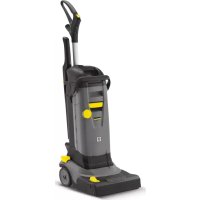
| Product type | Industrial dry vacuum cleaner |
| Brand | Kärcher |
| Model | SB VC 2 |
| Number of suction positions | 2 (SB VC 2) |
| Mains voltage | 220-230 V |
| Frequency | 50-60 Hz |
| Maximum power | 2 x 1380 W |
| Rated power | 2 x 1200 W |
| Max. air flow rate | 2 x 74 l/s |
| Max. vacuum | 25,4 kPa (254 mbar) |
| Sound pressure level | < 70 dB(A) |
| Filter type | Pleated flat filter (ref. 6.904-360.0) |
| Automatic filter cleaning | Yes, by air pulse after start |
| Intended use | Suction of dry impurities in the interior of motor vehicles |
| Commissioning | Reserved for trained specialist personnel |
| Routine maintenance | Empty the dirt collector 1-2 times per week; replace the filter once a year or depending on soiling |
| Safety | Danger: turn off the main switch before any intervention; observe safety instructions No. 5.956-249.0 |
| Spare parts | Pleated flat filter ref. 6.904-360.0, available at www.kaercher.com |
| Warranty | According to local distributor conditions; free repair of material or manufacturing defects |
| Weight | Not specified in the manual |
Frequently Asked Questions - SB VC 2 Kärcher
User questions about SB VC 2 Kärcher
0 question about this device. Answer the ones you know or ask your own.
Ask a new question about this device
Download the instructions for your Industrial vacuum cleaner in PDF format for free! Find your manual SB VC 2 - Kärcher and take your electronic device back in hand. On this page are published all the documents necessary for the use of your device. SB VC 2 by Kärcher.
USER MANUAL SB VC 2 Kärcher

Chairman of the Board of Management

S. Reiser
Director Regulatory Affairs & Certification
71364 Winnenden (Germany)
Tel.: +49 7195 14-0
Fax: +49 7195 14-2212
Winnenden, 2017/04/01

Please read and comply with these original instructions prior
to the initial operation of your appliance and store them for later use or subsequent owners.
- Before first start-up it is definitely necessary to read the safety indications Nr. 5.956-249.0!
- The non-compliance of the operating and safety instructions may lead to damages of the appliance and to dangers for the operator and other persons.
- In case of transport damage inform vendor immediately.
Contents
Environmental protection . . . EN 1
Danger or hazard levels . . . . EN 1
Proper use EN 1
Overview of the appliance. . . . EN 2
Device elements EN 3
Start up EN 3
Operation EN6
Care and maintenance . EN 7
Menu structure EN 10
Troubleshooting EN 14
Warranty EN 16
Accessories and Spare Parts. EN 16
Technical specifications EN 16
EU Declaration of Conformity. EN 16
Environmental protection

The packaging material can be recycled. Please do not throw the packaging material into household waste; please send it for recycling.
Old appliances contain valuable materials that can be recycled; these should be sent for recycling. Batteries, oil, and similar substances must not enter the environment. Please dispose of your old appliances using appropriate collection systems.
Notes about the ingredients (REACH)
You will find current information about the ingredients at:
www.kaercher.com/REACH
Danger or hazard levels
△DANGER
Immediate danger that can cause severe injury or even death.
WARNING
Possible hazardous situation that could lead to severe injury or even death.
CAUTION
Pointer to a possibly dangerous situation, which can lead to minor injuries.
ATTENTION
Pointer to a possibly dangerous situation, which can lead to property damage.
Proper use
Note: In the event of non-compliance with the conditions outlined in this Operating Instructions manual, Kärcher cannot assume any liability for damages to the machine or the customer vehicles to be cleaned as well as for any other damages.
- The machine is meant for sucking out dry dirt from automobile interiors.
- Sucking in inflammable substances, health-hazardous dusts and liquids indicates improper use of the machine and is therefore prohibited.
- This appliance is suitable for industrial use.
-A single-station (SB VC 1) or two-station (SB VC 2) variant is available.
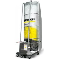
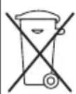
Overview of the appliance
Variant shown SB VC 2:
1 Control
2 Throwing in the coin
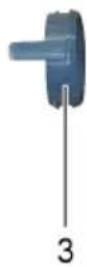
3 Main switch
4 Suction head 1
5 Bracket
6 Bow
7 Dirt receptacle
8 Suction head 2
9 Coin acceptor
10 Automatic filter dedusting switch
11 Intermediate ring
A Cable pass-through
SBVC1
B Cable pass-through
SBVC2
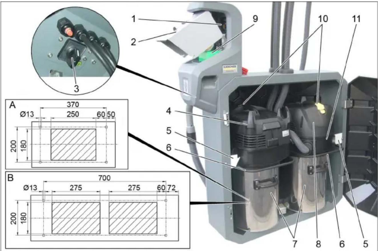
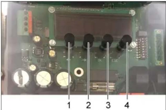
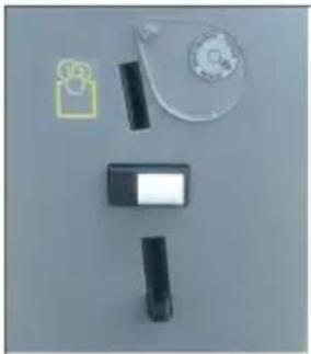
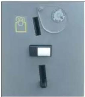
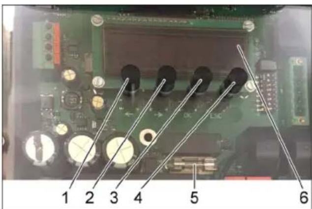
ntrol
1 LEFT key
2 RIGHT key
3 "OK" button
4"ESC" button
5 Fuse
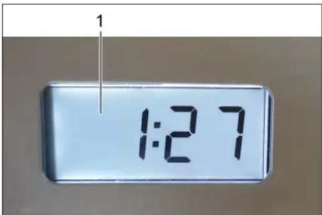
6 Display
Press the "OK" button for 2 seconds to access the unit control menu. The "Info" menu appears.
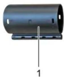
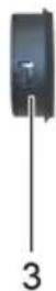
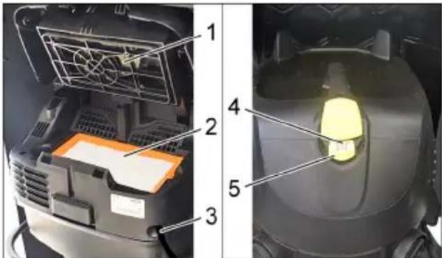
Device elements

1 Filter deducting
2 Flat fold filter
3 Power cord
4 Indicator lamp
5 Automatic filter deducting switch
Start up
ATTENTION
The device may only be operated by trained specialist personnel.
The flat pleated filter must always be in place while vacuuming.
Note
The suction hose is in the dirt receptacle.
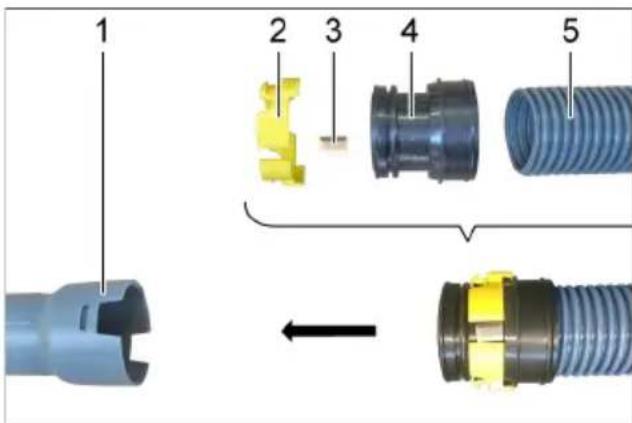
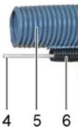
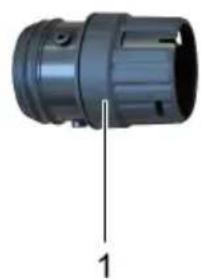
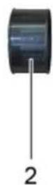
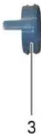
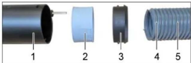
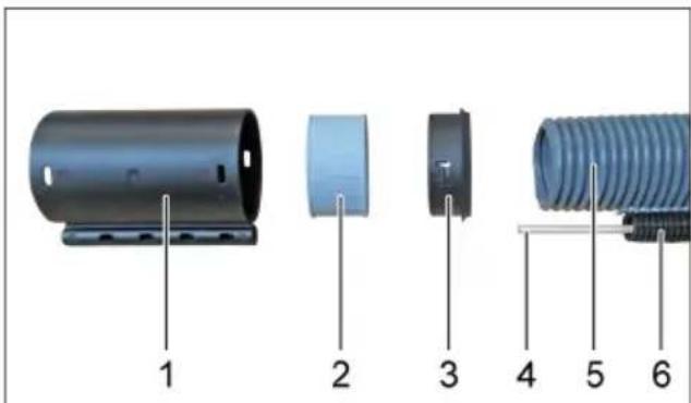
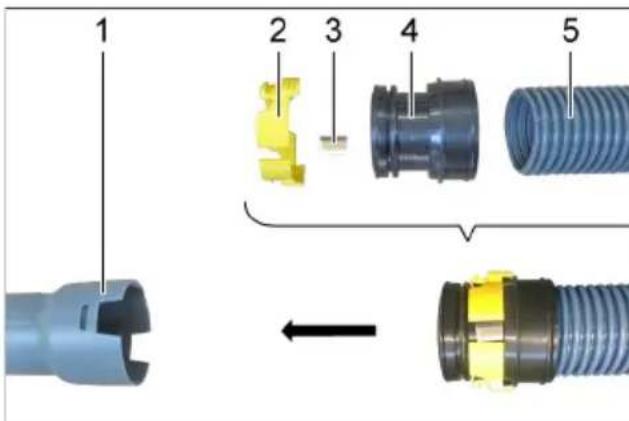
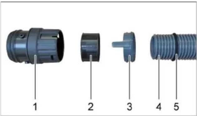
Suction hose installation
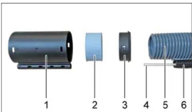
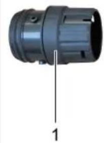
1 Hose coupling
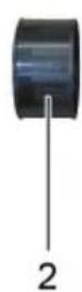
2 Threaded bush
3 Clamp ring
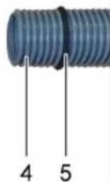
4 Fibreglass rod
5 Double casing suction hose
6 Guide hose
Mount the clamp ring, threaded bush and hose coupling on the double casing suction hose.
Insert the fiberglass rod in the guide hose and thread through the hose coupling.
1 Suction connection
2 Washer ring
3 Snap ring
4 Double casing suction hose
5 Sponge rubber seal
Push the sponge rubber seal over the double casing suction hose to just before the dual channel.
Guide the double casing suction hose through the suction hose intake.
Mount the snap ring, washer ring and suction connection on the double casing suction hose.
Connect the suction connection to the intermediate ring.
Before closing the door, the suction hose must be pushed in between both suction vacuum cleaners in order to be able to shut the door.
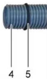
1 Double casing suction hose
2 Fiberglass rod
3 Sponge rubber seal
4 Suction hose intake
Insert the fibreglass rod, double casing suction hose and sponge rubber seal into the suction hose intake.
Note
The sponge rubber seal must be inserted flush in the suction hose intake.
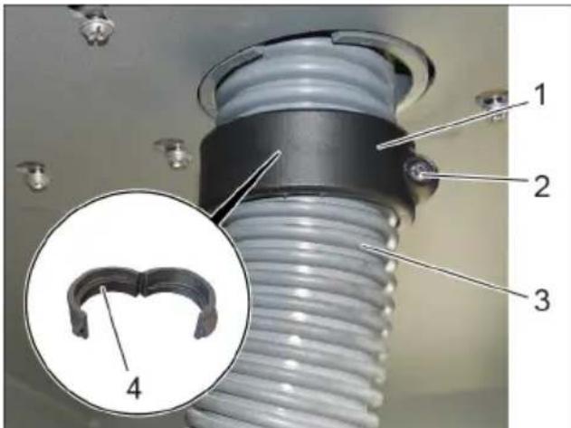
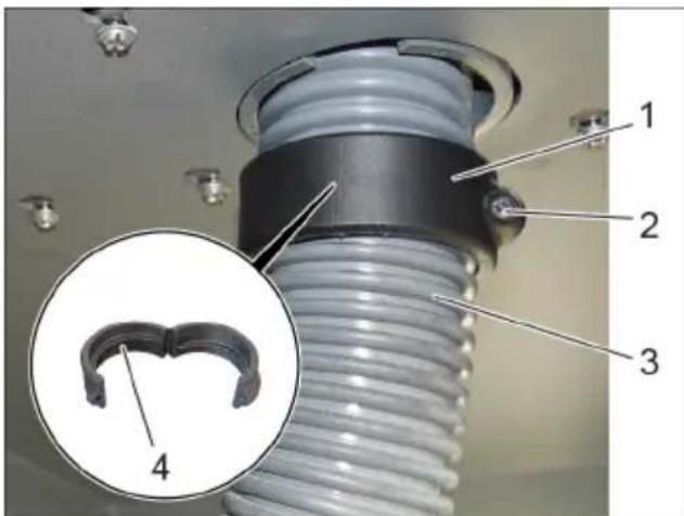
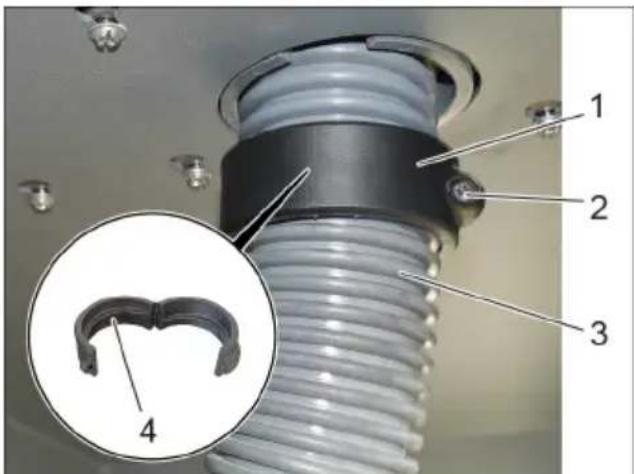
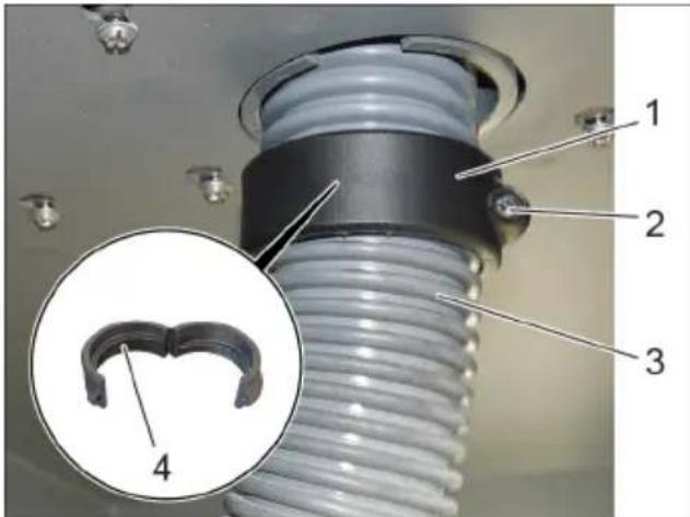
1 Rotating ring
2 Screw
3 Double casing suction hose
4 Thread in rotary ring
Fit the opened rotary ring around the double casing suction hose.
Close the rotary ring and secure with the screw.

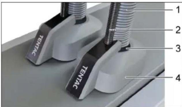
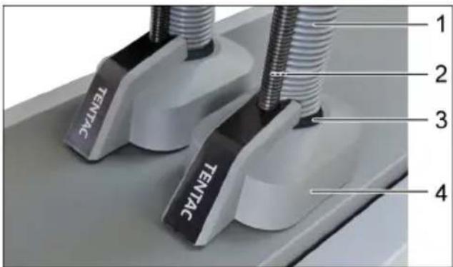
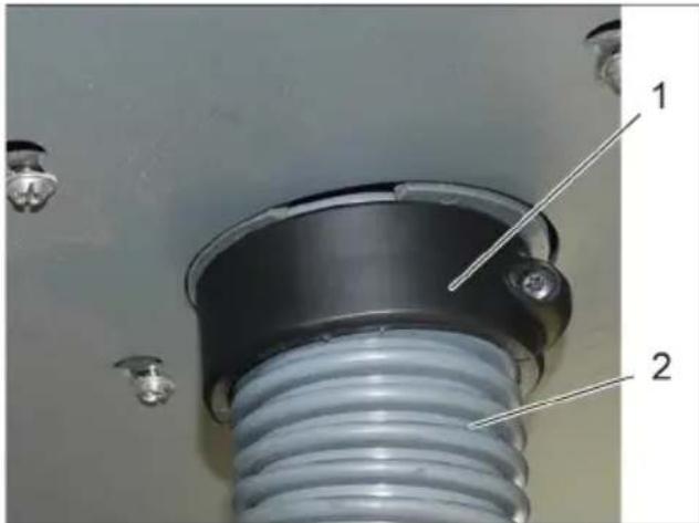
1 Rotating ring
2 Double casing suction hose
Pull the double casing suction hose downwards slightly.
Manually turn the rotary ring upwards so that the double casing suction hose is tensioned between the interior and exterior.
1 Car vacuuming tool
2 Threaded ring
3 Automatic nozzle anti-theft device
4 Tensioning ring
5 Operator suction hose
Adjust the length of the operator suction hose.
Mount the tensioning ring, threaded ring and automatic nozzle anti-theft device on the operator suction hose and attach to the automatic nozzle.

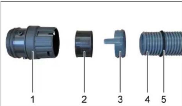
1 Hose coupling
2 Threaded bush
3 Clamp ring
4 Spring kink protection
5 Operator suction hose
Mount the clamp ring, threaded bush on the operator suction hose and insert into the hose coupling.

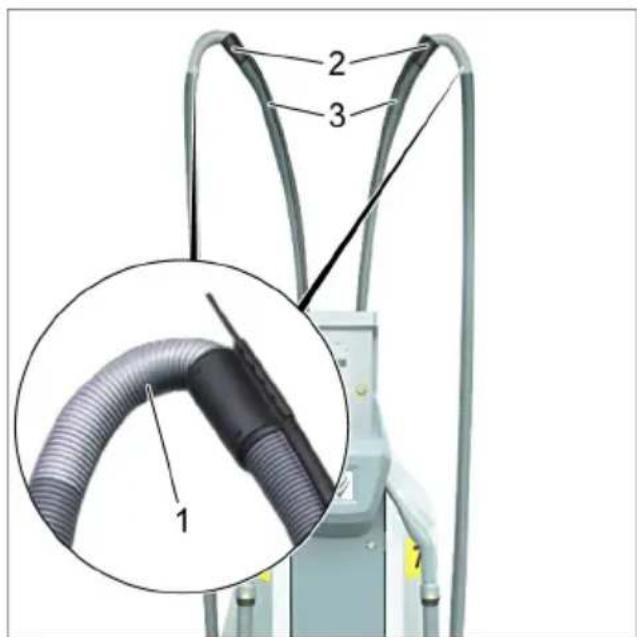
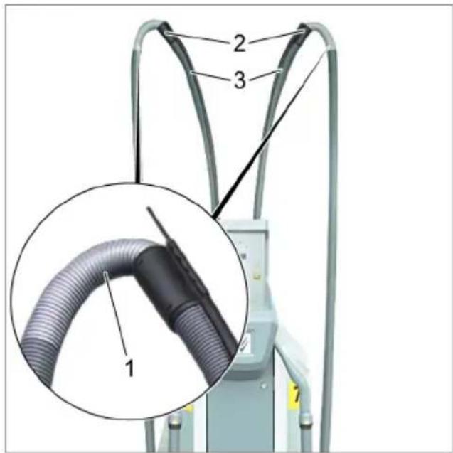
Overall view
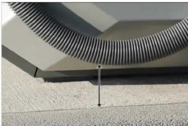
1 Suction hose operator with spring kink protection
2 Hose coupling
3 Double casing suction hose Installation information
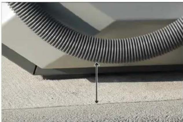
The spring kink protection must be installed on the hose coupling and not on the automatic nozzle.

Adjust hose length on site. When the automatic nozzle is attached, the suction hose operator may not lay on the floor, and must therefore maintain a minimum distance of 5cm to the floor. If necessary, adjust the length of the double casing suction hose.
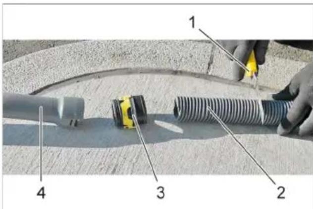
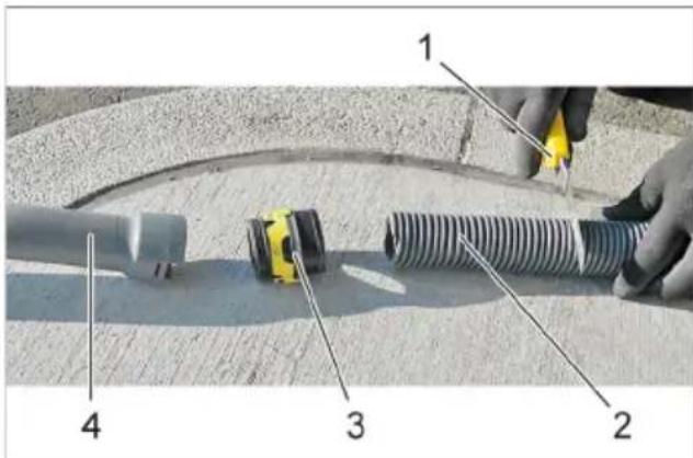
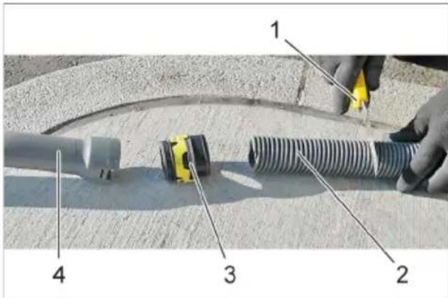
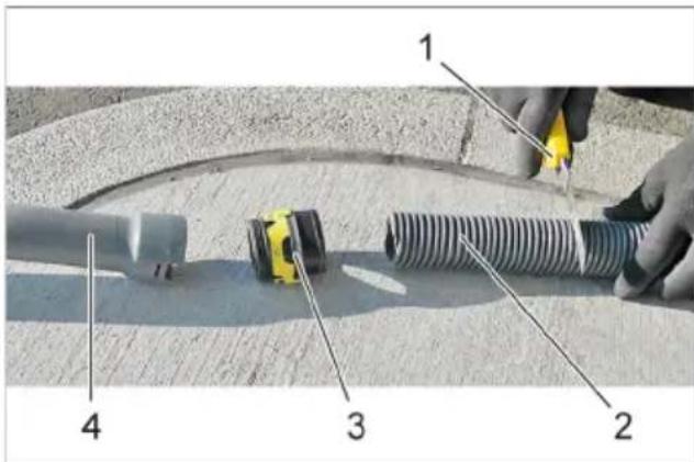
1 Knife
2 Double casing suction hose
3 Car nozzle mount
4 Car vacuuming tool
Press in the latches of the car nozzle mount.
Remove the car nozzle.
Unscrew the car nozzle mount.
Shorten the double casing suction hose using a knife.
Operation
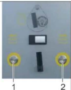
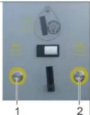
Differences between the start-up control
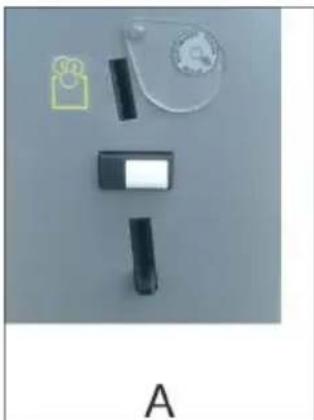
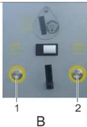
A SB VC
BSBC2
1 Vacuum selection button, left
2 Vacuum selection button, right
SBVC1
Vacuuming starts immediately after a coin is inserted.
SBVC2
After inserting a coin, select the corresponding vacuum cleaner station using the button. Vacuuming starts.
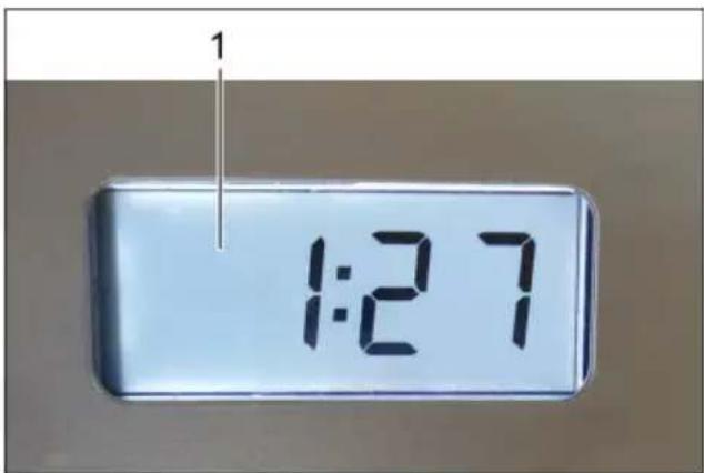
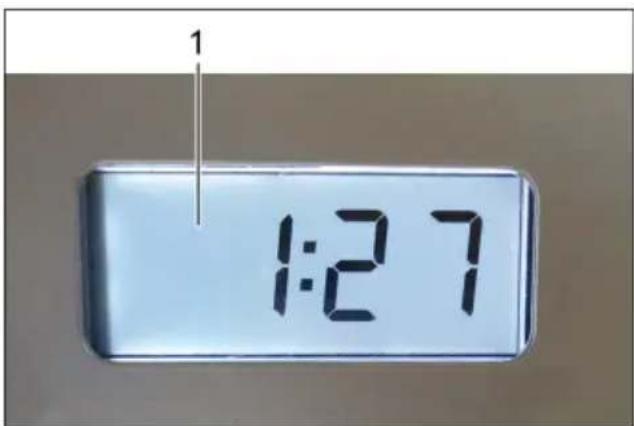
1 Display (optional)
Other versions:
With/without coin slot.
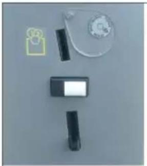
Automatic filter cleaning
The device has an automatic filter deducting function that is especially effective in removing fine dust. After starting vacuuming, the flat fold filter is automatically cleaned by three pulsating bursts of air.
Note: Automatic filter deducting is switched on at the factory.
Note: The automatic filter deducting function can only be switched on/ off when the appliance is switched on.
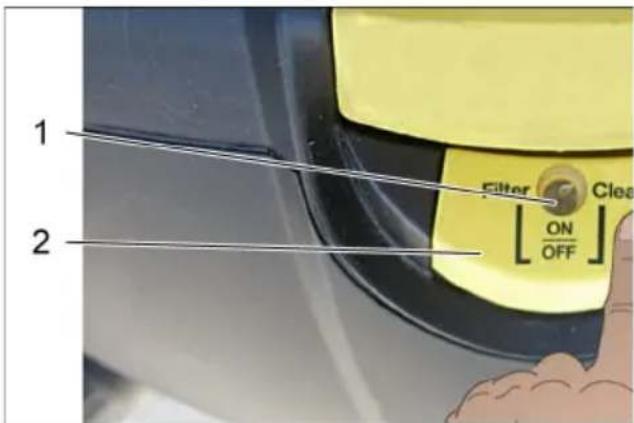
- To switch off automatic filter cleaning:
Activate the switch. Indicator lamp in the switch goes off.
- To switch on automatic filter cleaning:
Press the switch again. Indicator lamp in the switch glows green.
Note
Switching the automatic filter deducting function off leads to premature filter wear and a reduction in suction power.
Care and maintenance
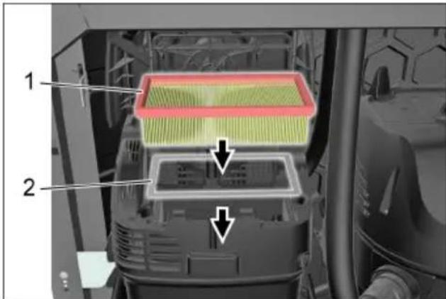
Exchanging the flat pleated filter
Note
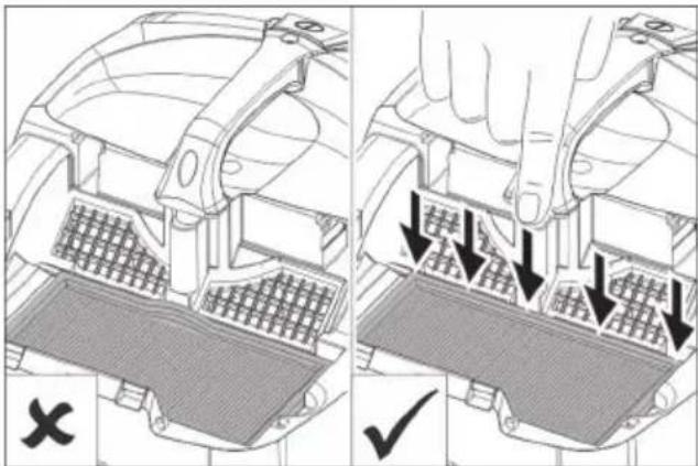
Change the flat fold filter annually, or as necessary and/or degree of contamination.
Check for correct seating when installing the flat fold filter.
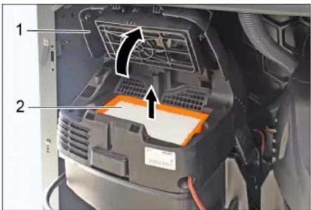
1 Filter cover
2 Flat fold filter
Open filter door.
Replace the flat pleated filter.
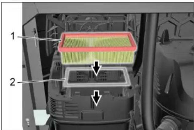
1 Flat fold filter
2 Metal frame
Ensure that the additional metal frame is inserted.
Close the filter door, it must lock into place.
Note
The flat fold filter with the item number 6.904-360.0 is resistant to moisture. We recommend using this filter when replacing the filter.
Emptying the dirt receptacle Checking the suction power
Note
Empty the dirt receptacle 1 to 2 times a week.
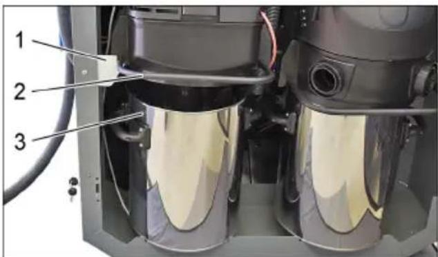
1 Bracket
2 Bow
3 Dirt receptacle
Lift up the suction head using the bow and set down in the bracket.
Remove the waste container.
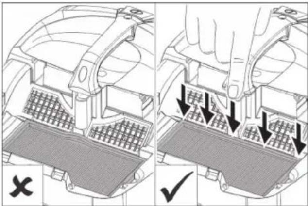
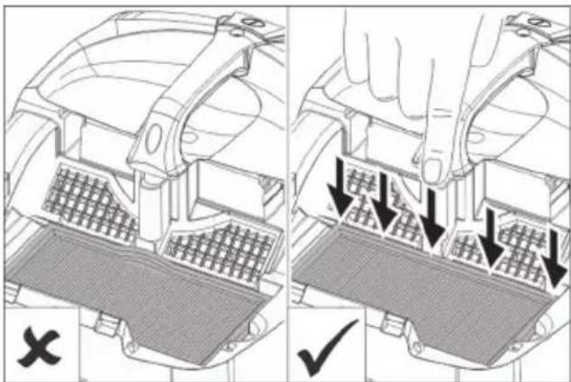
Note
Correct positioning should be ensured when putting the suction head in place. Before closing the door, the suction hose must be pushed in between both suction vacuum cleaners in order to be able to shut the door.
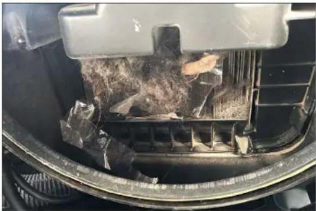
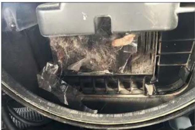
Each time after emptying the dirt receptacle, check the flat fold filter from below for coarse dirt and remove any soiling.
Check the suction power each time after emptying the dirt receptacle.
If the suction power is insufficient, the flat fold filter must be cleaned using the automatic deducting function.
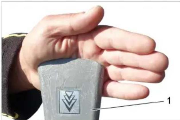
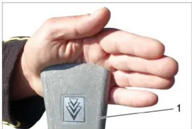
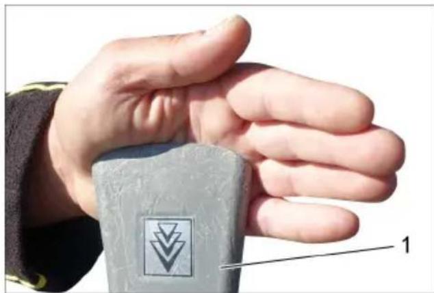
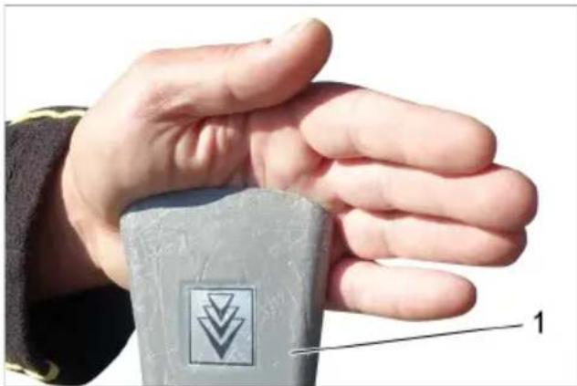
1 Car vacuuming tool
Seal off the car nozzle with your hand while the device is running.
The car nozzle must remain stuck to your hand through the vacuum generated by the device.
The car nozzle does not remain stuck to your hand, the flat fold filter must be cleaned using the automatic deducting function.
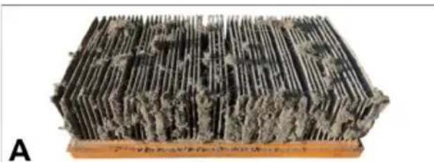
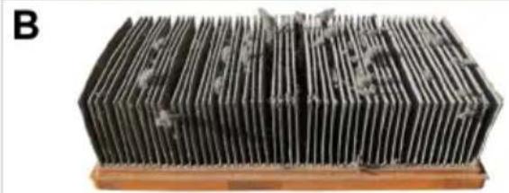
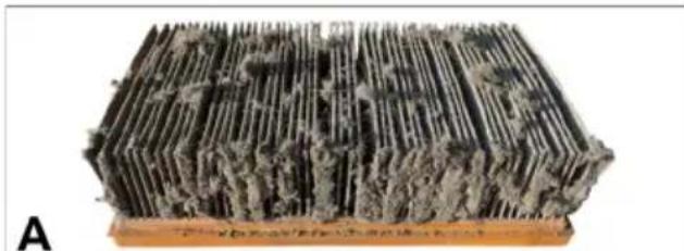
Cleaning the flat fold filter using the automatic deducting function
Step 1
Turn on the appliance.
Step 2
Switch the automatic filter deducting off using the switch.
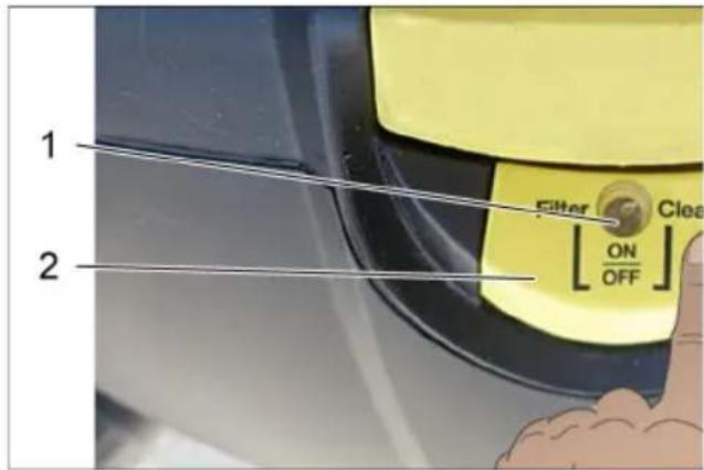
1 Indicator lamp
2 Automatic filter dedusting switch
Step 3
Seal off the car nozzle with your hand.
Note
Keep the car nozzle closed during automatic filter deducting.
1 Car vacuuming tool
Step 4
Switch the automatic filter deducting on using the switch.
Step 5
The flat fold filter is now automatically cleaned by three pulsating air bursts.
Repeat step 2 to step 4.
Repeat the procedure 5 to 8 times (or depending on the degree of soiling). Then check the suction power.
Note
The indicator lamp must light up green after the cleaning procedures.
Note
Cleaning the flat fold filter using the automatic deducting function removes the fine dust clogging the pores of the flat fold filter. Any existing fluff does not impair the suction power.
If necessary, carefully remove any existing fluff using a brush.
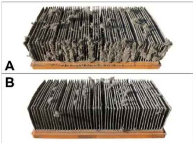
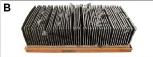
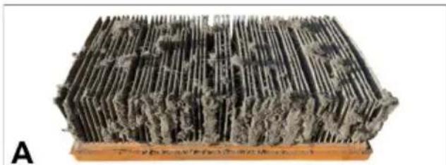
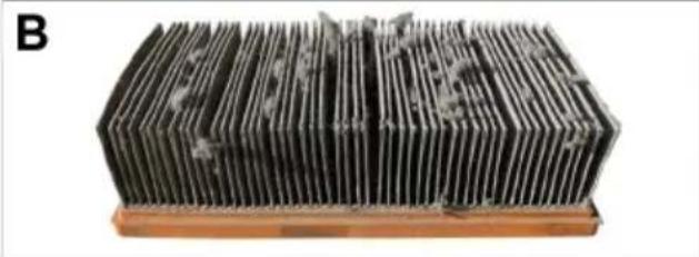
A Flat fold filter before cleaning
B Flat fold filter after cleaning
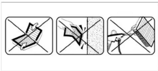
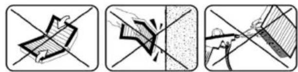
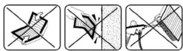
ATTENTION
The flat fold filter is damaged if kinked, beaten out or cleaned with compressed air.

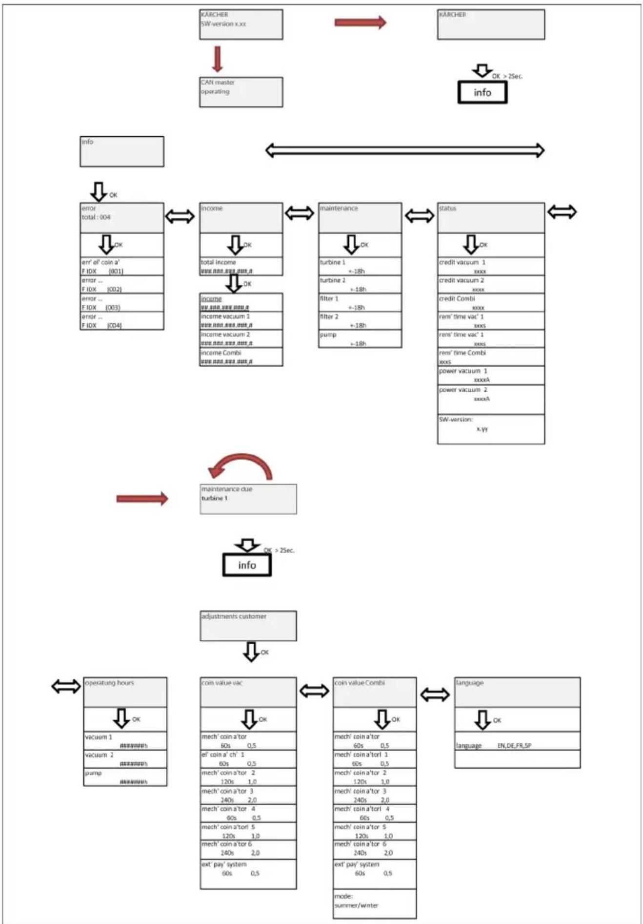
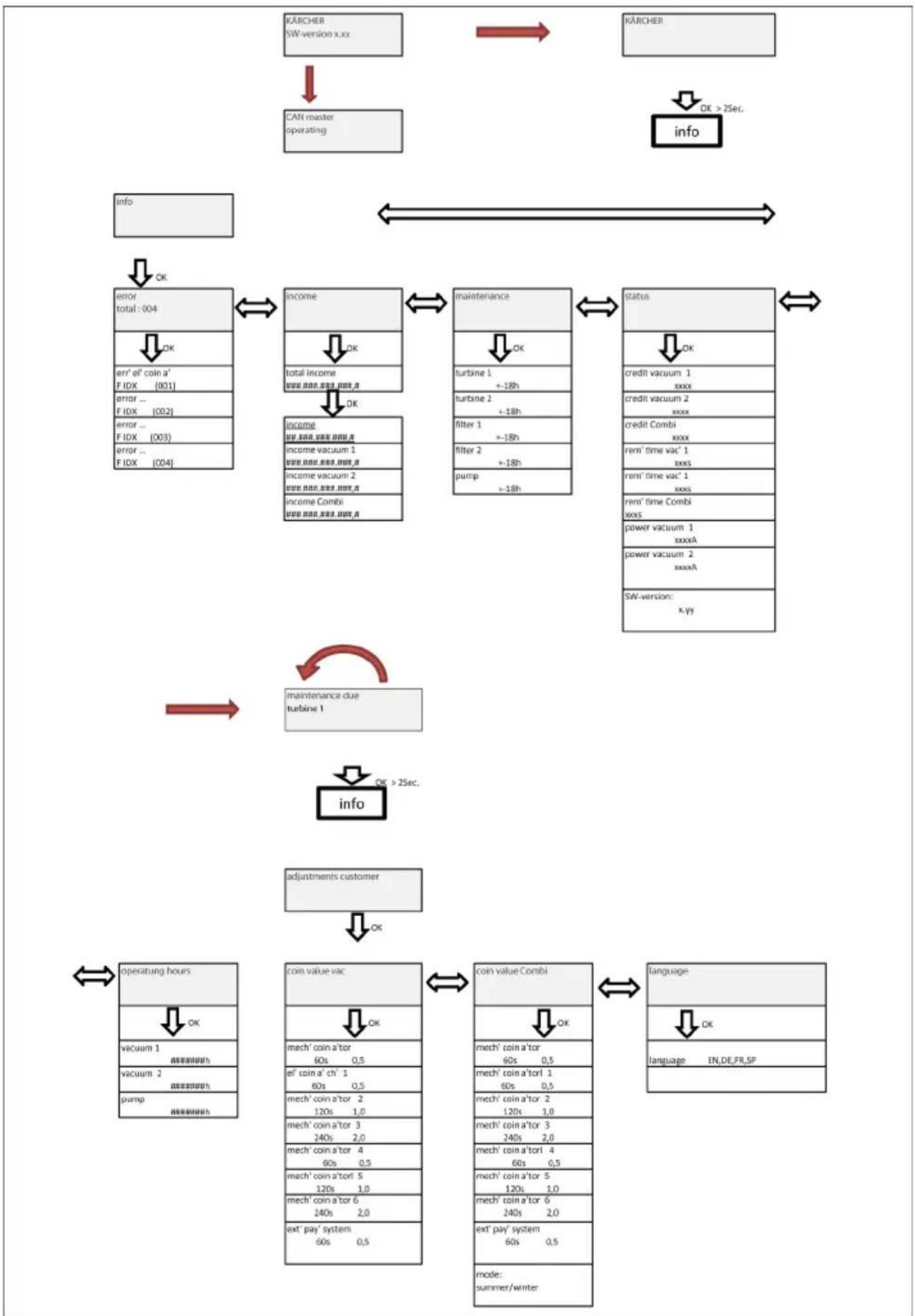
Menu structure
| Menu point Important | |
| CAN master operating | If the system is operated in CAN master mode (car wash plant), any settings can only be made on the central control. |
| error total:004 | To acknowledge the fault, switch off the main switch, remedy the fault, wait at least 5 seconds and switch the system back on again. |
| income | The total turnover cannot be reset. |
| OK | |
| total income ###.###.###.###.###. | Turnover / Turnover vacuum cleaner 1 / Turnover vacuum cleaner SG 2 / Turnover combined: The corresponding turnover can be reset. To do so, press the LEFT and RIGHT button simultaneously and confirm with the "OK" button. Cancel using the "ESC" button. |
| OK | |
| income ###.###.###.###. | Turnover / Turnover vacuum cleaner 1 / Turnover vacuum cleaner SG 2 / Turnover combined: The corresponding turnover can be reset. To do so, press the LEFT and RIGHT button simultaneously and confirm with the "OK" button. Cancel using the "ESC" button. |
| ###.###.###.###. | |
| income vacuum 1 | The corresponding turnover can be reset. To do so, press the LEFT and RIGHT button simultaneously and confirm with the "OK" button. Cancel using the "ESC" button. |
| ###.###.###.###. | |
| income vacuum 2 | The corresponding turnover can be reset. To do so, press the LEFT and RIGHT button simultaneously and confirm with the "OK" button. Cancel using the "ESC" button. |
| ###.###.###.###. | |
| income Combi | Can only be reset by Service. |
| ###.###.###.###. | |
| maintenance | |
| OK | |
| turbine 1 | The corresponding filter can be reset. To do so, press the LEFT and RIGHT button simultaneously and confirm with the "OK" button. Cancel using the "ESC" button. |
| + -18h | |
| turbine 2 | The corresponding filter can be reset. To do so, press the LEFT and RIGHT button simultaneously and confirm with the "OK" button. Cancel using the "ESC" button. |
| + -18h | |
| filter 1 | The corresponding filter can be reset. To do so, press the LEFT and RIGHT button simultaneously and confirm with the "OK" button. Cancel using the "ESC" button. |
| + -18h | |
| filter 2 | The corresponding filter can be reset. To do so, press the LEFT and RIGHT button simultaneously and confirm with the "OK" button. Cancel using the "ESC" button. |
| + -18h | |
| coin value vac | Note The menu item Mechanical coin acceptor is also used for setting the run time for the variant with a start button. |
| OK | → Mechanical coin acceptor run time 60s, coin value 0.5 |
| mech' coin a'tor 60s 0,5 | |
| el' coin a' ch' 1 60s 0,5 | |
| mech' coin a'tor 2 120s 1,0 | → Electronic coin acceptor Channel 1, run time 60s, coin value 0.5 |
| mech' coin a'tor 3 240s 2,0 | → Channel 2, run time 120s, coin value 1.0 |
| mech' coin a'tor 4 60s 0,5 | → Channel 3, run time 240s, coin value 2.0 |
| mech' coin a'torl 5 120s 1,0 | → Channel 4, run time 60s, coin value 0.5 |
| mech' coin a'tor 6 240s 2,0 | → Channel 5, run time 120s, coin value 1.0 |
| ext' pay' system 60s 0,5 | → Channel 6, run time 240s, coin value 2.0 |
| → External payment system run time 60s, coin value 0.5 | |
| coin value Combi | Note This mode can only be switched over for the combi-variant. Times are halved when the mode is switched to "Winter". The coin values remain the same. |
| OK | |
| mode: | |
| summer/winter |
Description of Function Keys
1 LEFT key
2 RIGHT key
3 "OK" button
4"ESC" button
Functions described with an \*:
LEFT key allows a movement to the left within the menu
RIGHT key allows a movement to the right within the menu
"OK" button allows and confirms modifi cations
"ESC" button step-by-step reversal, backward browsing to the basic display
Description of the menu
Note
Depending on how the system is equipped, irrelevant menus or pages are hidden. The last parameter selected remains visible on the display (e.g. total turnover...).
Select the parameter you want to set
Select the menu point with the LEFT and the RIGHT button.
Press OK to open the parameter group.
Use the LEFT and RIGHT buttons to select the parameter you want to set.
Set the parameter with a variable
Press the OK button.
The selectable variable blinks.
Use the LEFT and RIGHT buttons to select the variable value.
Press and hold the button for a swift change of the variable.
Press the OK button to save the selected value.
or
Press ESC to abort the change.
Setting a parameter with several variables
Press the OK button.
The selectable variable blinks.
Use the LEFT and RIGHT buttons to select the variable value.
Press and hold the button for a swift change of the variable.
Press OK briefly to save the value and to jump to the next variable.
Press the OK button for more than 1 second to save set values. or
Press ESC to abort the change.
Exiting the menu
Press the ESC ro return to the next higher menu.
The respective area can be exited by pressing the "ESC" button if the user is not in modification mode.
Troubleshooting
△DANGER
Switch the main switch (in the outer casing)
to "OFF" before carrying out any tasks on
the device.
| Failure Possible | cause Correction | ||
| Appliance is not running | Current supply interrupted (slot lock closed) | Check the cables, fuse and electronics | Qualified electrician |
| Coin acceptor dirty Clean the coin acceptor Operator | |||
| The slot lock in the coin acceptor does not open | Coin jammed, remove coin | Operator | |
| Slot lock in the mechanical coin acceptor jammed | Repair and/or replace the slot lock | Operator Customer Service | |
| Suction capacity decreases | Suction system clogged Remove blockage from the suction nozzle, suction hose, hose coupling or flat fold filter | Operator | |
| Filter cover not properly engaged | Correctly engage the filter cover | Operator | |
| Flat fold filter clogged Replace the flat fold filter Operator | |||
| Flat fold filter damaged Replace the flat fold filter Operator | |||
| Dust comes out during the vacuuming | Flat fold filter not inserted properly | Establish and/or observe the correct installation position for the flat fold filter | Operator |
| Flat fold filter clogged Replace the flat fold filter Operator | |||
| Automatic filter deducting is not working | Suction hose not connected properly | Connect the suction hose | Operator |
| Automatic filter deducting function switched off via Automatic filter deducting switch | Switch on the automatic filter deducting function (the LED on the Automatic filter deducting switch must light up) | Operator | |
| The automatic filter deducting function cannot be switched on/off | - Customer ser-vice | Operator | |
| The filter cover is not properly closed | Close the filter cover properly | Operator | |
| The suction head is not correctly positioned on the suction container | Position the suction head correctly | Operator | |
Fault codes
| Display Display | Faults Error description Operator correction | |||
| err' el' coin a' 001 | Electrical coin ac- ceptor defective Rem | ove, clean the coin acceptor | Call customer service. | |
| err' me' coin a' 002 | Mechanical coin ac- ceptor defective | |||
| err' buttom 1 003 | Start button/vacuum cleaner station se- lection button 1 is jammed | Check the start button | ||
| err' buttom 2 004 | Start button/vacuum cleaner station se- lection button 2 is jammed | |||
| err' turbine 1 005 | Turbine 1 defective Switch the main switch off and on Check whether the power switch is switched on for devices up to product number 010120 | main switch off and on Check whether the power switch is switched on for devices up to product number 010120 | ||
| err' turbine 2 006 | Turbine 2 defective | |||
| error relay 1 007 | Turbine 1 relay de- fective Switch the main switch off and on | in switch off and on | ||
| error relay 2 008 | Turbine 2 relay de- fective | |||
| overcurr'turb' 1 009 | Turbine 1 overcur- rent | Switch the main switch off and on | ||
| overcurr'turb' 2 010 | Turbine 2 overcur- rent | Check the filter for coarse contamination | ||
| maint' turb' 1 011 | Turbine 1 mainte- nance due | Note Maintenance intervals for turbine in the control ex- pired | ||
| maint' turb' 2 012 | Turbine 2 mainte- nance due | |||
| maint' filter 1 013 | Filter 1 maintenance due | Note Maintenance intervals for filter in the control expired | ||
| maint' filter 2 014 | Filter 2 maintenance due | |||
Warranty
The warranty terms published by the relevant sales company are applicable in each country. We will repair potential failures of your appliance within the warranty period free of charge, provided that such failure is caused by faulty material or defects in manufacturing. In the event of a warranty claim please contact your dealer or the nearest authorized Customer Service centre. Please submit the proof of purchase.
Accessories and Spare Parts
Only use original accessories and spare parts, they ensure the safe and trouble-free operation of the device.
For information about accessories and spare parts, please visit www.kaercher.com.
Technical specifications
| SB VC1 VC2 | |||
| Mains voltage V | 220-240 | 220-230 | |
| Frequency Hz 1 | ~ 50-60 | ||
| Max. perfor- mance | W 1380 | 2x 1380 | |
| Rated power W | 1200 2x | 1200 | |
| Air volume (max.) | l/s 74 2x | 74 | |
| Negative pres- sure (max.) | kPa (mbar) | 25,4 (254) | |
| Sound pres- sure level LpA | dB (A) | < 70 | |
| SB VC1 EC VC2 EC | |||
| Mains voltage V | 220-240 | 220-240 | |
| Frequency Hz 1 | ~ 50-60 | ||
| Max. perfor- mance | W 1380 | 2x 1380 | |
| Rated power W | 1200 2x | 1200 | |
| Air volume (max.) | l/s 60 2x | 60 | |
| Negative pres- sure (max.) | kPa (mbar) | 24,4 (244) | |
| Sound pres- sure level LpA | dB (A) | < 70 | |
EU Declaration of Conformity
We hereby declare that the machine described below complies with the relevant basic safety and health requirements of the EU Directives, both in its basic design and construction as well as in the version put into circulation by us. This declaration shall cease to be valid if the machine is modified without our prior approval.
Product: Dry vacuum cleaner
Type: 1.070-xxx
Relevant EU Directives
2000/14/EC
2006/42/EC (+2009/127/EC)
2011/65/EU
2014/30/EU
Applied harmonized standards
EN 60335-1
EN 60335-2-69
EN 60335-2-75
EN 50581
EN 55014-1: 2006+A1: 2009+A2: 2011
EN 55014-2: 2015
EN 61000-3-3:2013
EN 62233: 2008
Applied national standards
The signatories act on behalf of and with the authority of the company management.

H.Jenner
Chairman of the Board of Management

S. Reiser
Director Regulatory Affairs & Certification
Documentation supervisor: S. Reiser
Alfred Kärcher SE & Co. KG
71364 Winnenden (Germany)
Tel.: +49 7195 14-0
Fax: +49 7195 14-2212
Winnenden, 2017/04/01
www.kaercher.com/REACH
Niveau de danger
△DANGER
2006/42/CE (+2009/127/CE)
2011/65/EU
2014/30/UE
Chairman of the Board of Management

S. Reiser
Director Regulatory Affairs & Certification
Responsible de la documentation :
S. Reiser
Alfred Kärcher SE & Co. KG
71364 Winnenden (Germany)
Tel.: +49 7195 14-0
Fax: +49 7195 14-2212
Winnenden, 2017/04/01

www.kaercher.com/REACH
Livelli di pericolo
△PERICOLO
2006/42/CE (+2009/127/CE)
2011/65/EU
2014/30/UE
Chairman of the Board of Management

S. Reiser
Director Regulatory Affairs & Certification
71364 Winnenden (Germany)
Tel.: +49 7195 14-0
Fax: +49 7195 14-2212
Winnenden, 2017/04/01
www.kaercher.com/REACH
Gevarenniveaus
△GEVAAR
Chairman of the Board of Management

S. Reiser
Director Regulatory Affairs & Certification
71364 Winnenden (Germany)
Tel.: +49 7195 14-0
Fax: +49 7195 14-2212
Winnenden, 2017/04/01
www.kaercher.com/REACH
Niveles de peligro
△PELIGRO
2006/42/CE (+2009/127/CE)
2011/65/EU
2014/30/UE
Chairman of the Board of Management

S. Reiser
Director Regulatory Affairs & Certification
Responsible de documento:
S. Reiser
Alfred Kärcher SE & Co. KG
71364 Winnenden (Germany)
Tel.: +49 7195 14-0
Fax: +49 7195 14-2212
Winnenden, 2017/04/01

Leia o manual de manual original antes de utiliser o seu apare-
2006/42/CE (+2009/127/CE)
2011/65/EU
2014/30/UE
Chairman of the Board of Management

S. Reiser
Director Regulatory Affairs & Certification
71364 Winnenden (Germany)
Tel.: +49 7195 14-0
Fax: +49 7195 14-2212
Winnenden, 2017/04/01

www.kaercher.com/REACH
Faregrader
△FARE
En umiddelbar truende fare, som kan fore til alvorlige personskader aller ddd.
ADVARSEL
2006/42/EF (+2009/127/EF)
2011/65/EU
2014/30/EU

Chairman of the Board of Management

S. Reiser
Director Regulatory Affairs & Certification
71364 Winnenden (Germany)
Tel.: +49 7195 14-0
Fax: +49 7195 14-2212
Winnenden, 2017/04/01

www.kaercher.com/REACH
Risikotrinn
△FARE
A Flatt foldefilter for rens
B Flatt foldefilter etter rens
OBS
2006/42/EF (+2009/127/EF)
2011/65/EU
2014/30/EU
Chairman of the Board of Management

S. Reiser
Director Regulatory Affairs & Certification
71364 Winnenden (Germany)
Tel.: +49 7195 14-0
Fax: +49 7195 14-2212
Winnenden, 2017/04/01

www.kaercher.com/REACH
Risknivaer
△FARA
A Planfilter fore rengöringen
B Planfilter after rengöringen
OBSERVERA
Chairman of the Board of Management
S. Reiser
Director Regulatory Affairs & Certification
Dokumentationsbefullmaktigad:
S. Reiser
Alfred Kärcher SE & Co. KG
71364 Winnenden (Germany)
Tel.: +49 7195 14-0
Fax: +49 7195 14-2212
Winnenden, 2017/04/01

www.kaercher.com/REACH
Vaarallisuusasteet
VAARA
1 Painike VASEN
2 Painike OIKEA
3 Painike "OK"
4 Painike "ESC"
H.Jenner

Chairman of the Board of Management
S. Reiser

Director Regulatory Affairs & Certification
71364 Winnenden (Germany)
Tel.: +49 7195 14-0
Fax: +49 7195 14-2212
Winnenden, 2017/04/01
Piiv xpnoiopoiooTe Tn ou- okeun oac yia npwtn opa, dia- baote autcTc TTpwtotutteC odnyies xpntc, evpynoTE OUMWVA ME autcKai Kpa-tnote TcYIA MAAovTKn xpnoN n YIA TOV EIOEVO IIOKTNTn.
- Piv aTó TnV TpWtn XpHON δiaβaOTe OTWOBHNTOTE TIC UTOBεIεIc ασφαλεIac ap. 5.956-249.0!
-H mtnpnon twv obnyiw xphongs, ka- 0wcs kai twv uto8eiEewv aopaaiac, 1TOpEi va Tpokaolei 0TN OuOKEun n KIVDuvouc yia tov xpnoTn n aaatao.
-2επεριπτωσηβλαβωγκαταημεταφορα ειδοτοίησε αμέσωςθουναντιπόσωπόσας.
www.kaercher.com/REACH
Διαβάθμιση κίνδύνων
KINADYNO
Ia aεσα επaελομενo kivδuvo, o oIo-o μπopei va oθηnσει σε σoβapó tpaμa-tiμo n θavato.
△PPOEIAOIOIH∑H
Ia eovexoevn Epiikivouv n kataotaan, n oToia mTopei va odnynoe i 0e oBapop rau- patioo n thavato.
△PPOOxH
Chairman of the Board of Management

S. Reiser
Director Regulatory Affairs & Certification
71364 Winnenden (Germany)
Tel.: +49 7195 14-0
Fax: +49 7195 14-2212
Winnenden, 2017/04/01

www.kaercher.com/REACH
Tehlike kademeleri
△TEHLIKE

Chairman of the Board of Management

S. Reiser
Director Regulatory Affairs & Certification
71364 Winnenden (Germany)
Tel.: +49 7195 14-0
Fax: +49 7195 14-2212
Winnenden, 2017/04/01

Ipeed nepBbIM npImMeHneM BaWero np6opa npouHTaTe
3TyOpHnHaJIbHyIO INHCTpyKcIIO NO 3KcNPy-atauIN, NocJe 3TOrO DeIcTByIte COOTBeTCTBEHNO n COxpaHnte ee dIra DaIbHeIWe-ero IOnb3OBaHnIe IIN dIra CneDyUoIero BnaIeNbca.
www.kaercher.com/REACH
CTeNEHb onaCHOCTN
ONACHOCTb
Hn HnocpecmbeHNO 2po3aue onacnochocmu, Komopar npubodum kmjxekbIM yBeybAm UNU K Cmepmu.
△PENEUPPEXDEHNE
Длгьозможнoi nomenцuaьho onachou cumyaцuu, komopя можem npueecmu K mxeJBIM yeeyam unu K cmepu.
OCTOPOXHO
Yka3aHue Ha nomehuaJIbHO onachyIO cuMyauuO, Komopar MoXem npueecMu K nonyuHuO ne2Kux mpaem.
BHIMAHNE
Yka3aHue omHocumelbHO 603MOxHOJ noMeHuAJIbHO onaCHO cumyaauu, Komopara MoXem NOBney MamepuanbHbIy uep6.
IcnoJb3OBaHne nO Ha3NaYeHnO
Yka3aHne: Kompanna Karcher He Hecet HnKaKoI OTBeTCTBENHOCTN 3a NOBpeXdEHNr Iprbopa, NOBpeXdEHNr ABTOMObNJr KJIeHTa, KOtOpbl HeO6xOIMo NOnCTNTb, a TAKKe 3a DpyrHe NOBpeXdEHNr, KOtOpbl BO3HKnB Pe3yNbTaTe HecO6bIIODeHNr POLOKeHN HaCTOJeero pykoBODCTBa No 3KcPnyaTaUIN.
-Приборпразнадаз nauseдясбopa cyxix 3a rgязнь в caloHe TpaHcnpTbIX cpeДCTB.
-ИспОЛьЗOBaHnEМ He NO Ha3HaueHnIO CHTaETcR c6Op rOpUChx MaTePnaJIOB, BpeHOnДЯ 3dOpoBbЯ ПblN IN JxNdkOCTeI N IO3Tomy DaHHoe IcNoJIb3OBA-Hne 3aIpeucaetc.
-Данньи пибор пиrodeн дя поМышileHHORO прIMeHeHЯ.
-ДocTypeH OndHomeCTHbI (SB VC 1) nnn DByXMeCTHbI (SB VC 2) BapnaHT.
063op annapata
PpeDCTaBJIeH SB VC 2:

1 YnpaBneHne
2 Μεπβιπη onyckαнma MoHET
3ΓnaBHyBbIKJIOyateJeB
4 BcacbBaioua rnoBka 1
5ДерхаTeьb
6 Pyka
7 MycopHbI 6aK
8 BcacbBaioua rnoBka 2
9 MoHeTHbI KOHTpOJIbHnK
10 BbIKIOuATEIb aBTOMaTnueckoOuNCtKnΦnIbTpα
11 PpoknaDouHoe KOnbO
A Ka6eJIbHbI BBOd SB VC 1
B Ka6eJIbHbI BBOd SB VC 2
Cnctema ynpabJIeHna ycIpoIcTBOM

1 KhoNka BJIeBO
2 KhoNka BnPABO
3 Khonka "OK"
4 Khonka "ESC"
5 Ppeoxpanntb
6 Dusrnne
YTo6bI nonactb B MeHIO CnCTembl ynpabLeHnra YcTPOINCTBOM, HaxaTb N B TeueHne 2CeKynd ydepxnbTaB KhoNkY «OK». PnoBJIareTcmeHIO «UHΦopMaunr» («Info»).
Злем entblпрбoga

1 YnctKa fNJIbTpa
2Плоский сКладчатьйФИЛТр
3 CeTeBoN uHyp
4 Kontrponbna JAmna
5 BbIKIOUaTeIb aBTOMaTnueCKo OuNCTKnΦnIbTpTa
Hauano pa6oTbI
BHUMAHNE
Bc0ycmpoucmea e 3KcnpnyamauHIO MoXem npou36oobmbcra molbko obyeHHbIM nepcoHaIOM.
Ydaenue cknadyamzo funbmpa 06pempaabomblanpeuamaemc.
Yka3aHne
BcacbBaIOUHmIaHr HaxOHTcB KOHTeHepE dIra c6opa mycopa.
MONTAX BCacbBaIOUeRo WJnHaRa

1UJahroBoe coeHHeHne
2 Pe3b6OBAra BtUJka
3 3aXIMHoe KoIbIcO
4CTeKIOBOJOKOHbI CTePKeHb
5 BcacbBaHouuN mJnAHr c DBOHo oboJIOUKO
6 HanpaBnaIouca Tpy6ka
YCTaHOBtB 3axmHoe KOJbUo,pe3b-6OByu BTyIky N IJIaHROBoE COeINHe-Hne Ha BCacbIBaHUsn IJNaHr C DBOH-O6OJouKoN.
CTeKIOBOJOKOHbI CTePKeHb BCTaBnTb HAnpaBJIHOU Tpy6ky NpoBecTN Upe3 WJaHROBo COeINHeHne.
1 BcacbBaIOUm 3JIeMeHrT
2 YnnoTHnTeJIb
3Пужняшee cTOnOpHoe KOBbO
4 BcacbIbauOuN mJnaHr c DBOHOn oboJIOUKOJ
5 YnIOTHeHne n3 rY6aToi pe3INbI
HaDeTb yNIOTHHeHne n3 rY6aToi pe3n-HbI Ha BCaCbIBaIOUm NJIaHr C DBOHOrOboJOnQoN I NOBHyTb NOHTn Do DBOHOro KaHaJa.
→ПювECTN BCaCbIBaIOUmIshlaHr cДВоHOr O6OLOyKoYepe3 KpePJIeHneшlaHra.
YCTaHOBnTb npyXnHjaUee cToOpHoe KOJIbUO, yNlOTnHTeJIbHOe KOJIbUO IN BCaCbIBAIOUIN NaTpY6OK Ha BCaCbIBaHOUIN UJNaHr C DBOHON O6OJouKoN.
→ PnpcoeHnHTb BCacbBaIOuI ni NaTpy-6OK K npoknaOCHOMy KOJIbUy.
→ПердзakpbBaHnemДВepи BCacbBaIoumшlaHr Heo6xOdmo npOBecTmexKdy DByMa DByMa nbIleCocAMN,TO6bl DBep MoIa 3AkpbITbcra.

1 BcacbBaUoHm UHaHr C DBOHOr OboJIOuKoI
2CTeKIOBOJOKOHbI CTePKeHb
3 YnnotHeHne n3 ry6aToi pe3nHbI
4 KpenneHnBcacbBaiooJero UHa
BCTaBnTb CTeKNOBOJOKOHbI CTepeXeHb, BCaCbIBaIOUmN UJNaHr C DBOHOnOboJouKoN u yIpOTHeHne n3 rY6uToi pe3INbI B KpePJIeHne BCaCbIBaIOUcero UJNaHra.
Yka3aHne
YyNtHeHne n3 r6yatoN pe3nHbI DOJXHO 6bITb BCTaBJeHO B KpeJIeHne BCacBaIO- Uero WJahra 3aNoDnUo.
1BpaaouoeecKolbfo
2 BnHT
3 BcacbIbauouiuHc DBOHoi oboJIOUKOI
4 Pe3b6a Bpa7aiooerockOJIbua
YCTaHOBtB OTKpbIToe BpaUOuEecr KOJIbU O Ha BCaCbIBaIOuN MJNaHr C DBOHOr OboJOnKoN.
3aKpbIb BpaUaHooeecKoJIbOu 3a-KpeNITb Wypynom.

1BpaaiooeecKolbco
2 BcacbIbaIOuI MuaHr C DBOHOr o6oJIoUKOI
→ TOnTMyTb BCaCbIBaIOuN MNaHr C DBOH0 O6OJouKo CJerKa BHN3.
→ Пювернь врашаюшеся кольцо pyкои Вьерх Тak,чTOбы BCacьВаIOшилshаHR BbITЯнсmaMeЖdy BHeшHeи BHyтpeHHeиоблacrMn.

1 BcacbBaiooee conno
2 Pe3b6OBoE KOnbUo
3 3aunTa OT KpaKn aBtOMoNbHOH Ha- caKn
43aXIMHoe KOJIbIO
5 BcacbBaOuI WnAHN dIy onepaTopa
OTKOppeKtnpOBAbI dINHy BCacbIbaIO- Uero IHaHra dIg onepaTopa.
YcTaHOBnTb 3aXIMHoe KOJbO,pe3b-6oBOe KOJIbOu n 3aUHTy OT KpaKn aBTOMo6nJBHoH HacaKn Ha BCacbIBaIO-UnnI JnA Hn OepaTopa N BCTaBnTB aBTOMo6nJBHyO HacaNk.
1卍naHroBoe coeHHeHne
2 Pe3b6ObaB TyJaKa
3 3aXIMHoe KOJIbIcO
4 PnyxHa dJa 3aunTbI OT nepeRn6a
5 Bcacbibaoum shaHr JnepaTopa
YCTaHOBtB 3axmHoe KOJIbI O npe3b-6OByIO BTyIKy Ha BCacbIBaIOuN IJNaHrДЯ ONEpaTopa N BCTaBtB B IJNaHROBOE COeINHeHne.

O6nnBnD
1 BcacbBaUoHm UHaHr DnI onepaTopa C npyHOn 3aunTbI OT nepeRn6a
2 ⅡlaHroBoe coeINHeHne
3 BcacbBaIOUmI UHaHr C DBOHOr O6OJNoyKoI
HctpyKnno MoTaxy
IpyxHa 3aunTbI OT nepeRn6a DOJnxHa 6bITb MOHTnpOBaHa Ha IJIaHROBoI MyTe, a He Ha HacaKe dJa aBTOMo- 6nJa.

→ДиHyшногаOTKOppeKTnpoBaTbNo MeCTy.Пи HabeшeHHoN aBTOMO6nHb-HoH HacaJKe BCacbIbAIOUIN WlaHr He DoJIkeH KacaTbCЯ NOJa; MHNMaJIbHOe pacCTOraHne DO NOJa DoJIxHo COCTaBJIaTb 5 CM.
Ipn Heo6xOaHMoCTn OTpeRyIuPoBaTb DInHy BcAcBlaHoJero WJaHra C DBOHoi OboJouKoI.
1 Hox
2BcacbIbauouiuHn cDBOHOO oboJIOUKOI
3 KpenJIeHHe BCacbIbAIOJero conJa
4 BcacbBaiooee conIIO
3aKpeNTbΦnKcaTOpbl K KpeNHeHIO BCacbIBaUoero conla.
→ CHaTb BcacbIbAiooee connlo.
OTBnHTntb KpeIJIeHHe BCacbIbAIOUeRO cONIIa.
YKOPOTITb BCacbIBaIOUIM UJNaHr C DBOHON OBOJNOUKO C NOMOUIHOHOXA.
YnpaBJIeHne
OTnue cnTeM 3anycka
A

B
ASBVC1
BSBVC2
1 Khonka Bb6opa nbinecoca cneBa
2 Khonka Bb6opa nbilecoca cnpaba
SBVC1
Ipocecc BcacbHaHna HauHaeTc npa3y nocJe onyckaHn MOHeTbl.
SBVC2
Iocne onyckaHnma MOHeTbIC NOMOuBIO KHOKN BbIbpaTb COOTBeTCTByUoUee MeCTO nbIeCoca. HauHaetc npouec CbacblBaHn.
1 Dicnne (onua)
Дугne Испонненя:
c/6e3 onyckaHn MOHeT
A B T O M A T N U C E C K A Y N C T K A Φ N J B T P a
YcTpoIcTBO OCHaUeHO aBTOMaTnueCKoO uHCTKoN pINbTpA, KOTopA Oco6eHNO 3ΦΦeKTnBHa npM MeIKo Nbln. PpN 3Tom nlockn cKnaDuaTbI NblTp nocne 3anyCKa npOceDpybl BCacBbAHn aBTOMaTnueCKn OuHuaetcN oCpeDCTBOM Tpex NylbcnpyUoXn NHeBMaTnueCKNX yapOB.
Yka3aHHe: ABTomatnuecka YnCTKa 0nIb- Tpa 3aBepuNTcra CamoCTOReTbHO.
Yka3aHHe: BkIIOUeHHe N BBKIIIOUeHHe aBTOmatnuecko YNCTKn QINbTpA BO3MOXHO TOJbKO np IN BkIIOUeHHOM yCTpOJCTBe.
- BbIKIIOHTb aBTOMaTnueCKyIO YNCTKy ΦnIbTpɑ:
HaxaTb Ha BbIKIOuAteIb. KoHTpOnb-Ha JAmNoUka Ha BbIKIOuAteJe NOTyX- Het.
-BKIOUHTb aBTOMaTnueCKyIO YNCTKy 0nIbTpTa:
CHOBA HaxaTb Ha BbIKIOuataTeIb.3arOpTcra 3eJIeHa RA KOHTPOJbHa JAmNoyKa Ha BbIKIOUaTeJIe.
Yka3aHne
OTKIOUeHHe cyHKuIN OUnCTKn cNbTpa npIBoDnT KnpExdEBpeMeHHOMy n3HOCy cNbTpA N K CHIXeHIO MOUHOCTN BCacblBaHn.
YxOДи TeXHnYeecKoe 06cIyXnBaHne
3aMeHa cKlaAdyatoRo 0nIbTpap
Yka3aHne
IIOCKN CKJaauaTbI ΦnIbTp MeHAreJbExKeoDHO IIN NO Mpe Heo6XoDMocTN B3aBNCIMOCTN OT CTeNEHN 3aRpa3HeHn.
3aKpbItb pyKO BcacbBaHOoee conno.
yKa3aHne
Bo Bpemr aBtOMaTHueCKo OUHCTKn FnIb- Tpa BCacbIBaIOuiee cONIO DOJXHO 6bITb 3aKpbITbIM.
1 BcacbBaiooee conno
War 4
BkHIOHTb aBTOMaTnueckyIO ONUCTKy 1IbTpac NOMOsbIO nepeKIOuataTeJ.
War 5
Tenepb nlockn cknaadyaTbI ΦnIbTp aBTOMaTnueCKN OUnuaeTcA C NOMO- uTo Tpex NybcnpyUoX NHeBMaTnueckx yDapOB.
War2-War4noBTopraTcra.
NobtoptB npoecc 5-8 pa3 (nIn B 3aBVCIMOCTN OT CTeENH 3arpy3HeHNA. 3aTeM npOBepTb MOUHOCTb BCacbIBaHHJ.
Yka3aHne
Iocne npocecca ouncTk KOHTpoJbHa JAmnoUka DoJxHa 3aRopeTbcra 3eJeHbIM UBeTOM.
Yka3aHne
Bo Bpem oynctkn nlockoro cknaDyatoR Ounbtpa c nOMOu bIO aBtOMaTneCKo OunCTKn nnbtpa ydaJareTcMeIkae Nblb, KOTopra 3abNaet nopblnlockoro CKnAutaTO r hnBtpa.
CobpaBwneec BOpCNHKe He BnIaHT Ha MOUHOCTb BCaCbIBaHn.
Pn Heo6xOIMOCn OCTopoXHO ybePeTecyIeCTByIOUne BOPCNHKn C NOMOuHou IETKN.
He c2ubmb, He ebubambu He ouuamcbckamb603dyxom nlocku cknaqambuΦunbmp, ymo6bI He noepedum b ezo.
CTpykTypa MeHko
BbI6paTb Homep yCTaHaBnBaemoro napaMeTp a
BbIbpaTb nyHKT MeHIO C NOMOu bIO KHO-nok CJEBA n CnPABA.
OTkpblb rpynny napaMeTpOB c nomOuKHOKN,OK".
BbI6paTb yCTaHaBnBaEmbI npaMeTp KhoNkaMn BJIEBO n BnPABO.
YcTaHOBtB NepeMeHHbIe npaMeTpa.
HaxaTb KhoNky OK". HactpanBaemoe 3HaueHne nepemehHOI MraeT.
YcTaHOBnTb 3HaueHne nepeMeHHbIX c nOMoUbIO KHOJOK BJIEBO n BnPABO. IJIa 6bIcTpOro n3MeHeHnpeMeHHbIX yIepXKNBaTb KHOJky B HaxaTom noJIOJKeHn.
CoxpaHHTb 3HaueHHe HaXaTneM KhoNKn "OK".
JIN
OTMeHHTb N3MeHHeHMy MoXHo nOcePeDCTBOM HaXaTnK HONKn "ESC".
YcTaHOBnTb napaMeTp c HeCKoJIbKIMN nepeMeHHbIMN.
→ HaKaTb KhoNky,OK".
HactpanBaemoe 3HaueHne nepemeHHOH Mnraet.
YCTaHOBnTb 3HaueHne nepeMeHHbIX C nOMoUbIO KHONoK BJIEBO u BnPABO. IJIa 6bIcTpOro n3MeHeHnI nepeMeHHbIX yJepXnBaTb KHOInKy B HaXaTom NOJIOKeHN.
CoxpaHntb 3NaueHne nyTem kpaTkoro HaxkataHa KhoNky,OK" n OndHOpeMeHHo NpeeHTN KdpYrIM NepEmHbIM.
CoXpaHnTb yCTaHOBJIeHHoe 3HaueHHe IocpeIcTBOM dIITeJIbHO rHaKaTna (1 ceKyHda) Ha KhoNky ,OK". IIN OTMeHnTb N3MeHEnr MoxHo nocpeIcTBOM HaxKaTna KhoNKn "ESC".
BbIHTn3 MeHIO
→Пи Нжати Na KhoNky „ESC" MOxHo npeeTn B MeHIO 6OJee BBICOKoro ypoBHa.
I3 coOTBeTCTByUoSei Oblaactn MeHIO MOKHO BbIITN Pn NOMOUs KNOHKn «ESC》,ecIN IOnb3OBaTeJIb He HaxODNTcB peKIMe U3MeHeHna.
Pomoub B cnyae HeNoJaIOK
ONACHOCTb
Ipeod npoedeHue m IIObix pa6om Ha ycmpoucmee ycmaHOumb 2naEBiu 8blKIOUaMeIb (80 BHeuHem Kopnyce) e noJnoXeHue «OFF».
TabnueB3aKoOpOBaHHOM BnDE.
Pn3TOMOTdEnbHbIeUΦpbl IMeIOT cNeDyIOOee 3HaueHHe::
Приимер: 30190
3 roB BbInycka
0 CTOnTeBbInycka
1 DecaTnIeTne BbInycka
9 BTopa CnDpa Mecaa BbInycka
0 nepBaunpa Mecaa BbInycka
TakIM o6pa3OM, B daHHOM npHMepe KoD 30190 O3Haayet DaTy BbInycka 09/(2)013.
PpHaJnEeXHoCTN 3aNaChbIe deTaJIi
IcnoJb3yIe opnHaJIbHbIe npHaJIeKHOCTN 3aIpaCTN - TOnbKO OHI rapaHTNpyoT 6e3OpacHyO n 6ecpepeBoHyO pa60Ty yCTpoiCTBa.
HΦopMaUO O npHaJnEJXHOCTx N 3a- pTAcTEx Bb MoKeTe HaHTN Ha caTte www.kaercher.com.
TexHnueckne daHHbIe
Chairman of the Board of Management

S. Reiser
Director Regulatory Affairs & Certification
YIIOHOMOeHHbI COtpdHnK NO BeDeHNIO DOKyMeHToo6opota:
S. Reiser
Alfred Kärcher SE & Co. KG
71364 Winnenden (Germany)
Tel.: +49 7195 14-0
Fax: +49 7195 14-2212
Winnenden, 2017/04/01

www.kaercher.com/REACH
Veszély fokozatok
△VESZÉLY
1 BALRA gomb
2 JOBBRA gomb
3 "OK" gomb
4 "ESC" gomb
H.Jenner Chairman of the Board of Management

S. Reiser
Director Regulatory Affairs & Certification
71364 Winnenden (Germany)
Tel.: +49 7195 14-0
Fax: +49 7195 14-2212
Winnenden, 2017/04/01

www.kaercher.com/REACH
Stupné nebezpečí
△NEBEZPECI
2006/42/ES (+2009/127/ES)
2011/65/EU
2014/30/EU
Chairman of the Board of Management

S. Reiser
Director Regulatory Affairs & Certification
71364 Winnenden (Germany)
Tel.: +49 7195 14-0
Fax: +49 7195 14-2212
Winnenden, 2017/04/01

Pred prvo uporabo Vase naprave preberite to originalno navo
www.kaercher.com/REACH
Stopnje nevarnosti
NEVARNOST
Zadevne directives EU:
2000/14/ES
2006/42/ES (+2009/127/ES)
2011/65/EU
2014/30/EU

Chairman of the Board of Management

S. Reiser
Director Regulatory Affairs & Certification
Pooblascena oseba za dokumentacio: S. Reiser
Alfred Kärcher SE & Co. KG
71364 Winnenden (Germany)
Tel.: +49 7195 14-0
Fax: +49 7195 14-2212
Winnenden, 2017/04/01
www.kaercher.com/REACH
Stopnie zagrożenia
△NIEBEZPIECZENSTWO
2006/42/WE (+2009/127/WE)
2011/65/EU
2014/30/UE

S. Reiser
Director Regulatory Affairs & Certification
Administrator dokumentaci:
S. Reiser
Alfred Kärcher SE & Co. KG
71364 Winnenden (Germany)
Tel.: +49 7195 14-0
Fax: +49 7195 14-2212
Winnenden, 2017/04/01
www.kaercher.com/REACH
Trepte de pericol
△PERICOL
Pericol iminet, care duce la vatakari corporale grave sau moarte.
△AVERTIZARE
Posibila situatie periculoasa, care ar puteaduce la vatakari corporale grave sau moarte.
△PRECAUTIE
Indica o posibila situatie periculoasa, care ar putea duce la vatakari corporale usoare.
ATENTIE
Indicatie referitoare la o posibila situatie periculoasa, care ar putea duce la pagube materiale.
Utilizarea corectă
Directive UE respectate:
2000/14/CE
2006/42/CE (+2009/127/CE)
2011/65/EU
2014/30/UE
Norme armonizate utilize:
EN 60335-1
EN 60335-2-69
EN 60335-2-75
EN 50581
EN 55014-1: 2006+A1: 2009+A2: 2011
EN 55014-2:2015
EN 61000-3-3:2013
EN 62233: 2008
Norme de aplicare nationale:
Chairman of the Board of Management

S. Reiser
Director Regulatory Affairs & Certification
71364 Winnenden (Germany)
Tel.: +49 7195 14-0
Fax: +49 7195 14-2212
Winnenden, 2017/04/01

Pred prvym pouzitim vasho zariadenia si precitajte unto po
2006/42/ES (+2009/127/ES)
2011/65/EU
2014/30/EU
Chairman of the Board of Management

S. Reiser
Director Regulatory Affairs & Certification
71364 Winnenden (Germany)
Tel.: +49 7195 14-0
Fax: +49 7195 14-2212
Winnenden, 2017/04/01
Pije prve uporabe Vaseg ureda ja procitajte ove originalne radne upute, postupajte prema njima i saucuvaje ih za kasniju uporabu ili za sljedeceg vlasnika.
www.kaercher.com/REACH
Stupnjevi opasnosti
OPASNOST
2006/42/EZ (+2009/127/EZ)
2011/65/EU
2014/30/EU
Primijenjene uskladene norme:
EN 60335-1
EN 60335-2-69
EN 60335-2-75
EN 50581
EN 55014-1: 2006+A1: 2009+A2: 2011
EN 55014-2: 2015
EN 61000-3-3: 2013
EN 62233: 2008
Primijenjeni nacionaln standards
一
Chairman of the Board of Management

S. Reiser
Director Regulatory Affairs & Certification
Opunomoceni za izradu dokumentacije: S. Reiser
Alfred Kärcher SE & Co. KG
71364 Winnenden (Germany)
Tel.: +49 7195 14-0
Fax: +49 7195 14-2212
Winnenden, 2017/04/01

Pre prve upotrebe Vaseg uredaja procitajte ove originalno
www.kaercher.com/REACH
Stepeni opasnosti
OPASNOST
Ukazuje na nepsredno pretecu opasnost koja dovodi do teških telesnih povreda ili smrti.
UPOZORENJE
Ukazuje na eventualno opasnu situaciju koja moze dovesti do tešikh telesnih povreda ili smrti.
△OPREZ
Napomena koja ukazuje na eventualno opasnu situaciju, koja moze izazvati lakse telesne povrede.
PAZNJA
Napomena koja ukazuje na eventualno opasnu situaciju koja moze izazvati materijalne stete.
Namensko korišćenje
2006/42/EZ (+2009/127/EZ)
2011/65/EU
2014/30/EU
Primenjene uskladene norme:
EN 60335-1
EN 60335-2-69
EN 60335-2-75
EN 50581
EN 55014-1: 2006+A1: 2009+A2: 2011
EN 55014-2: 2015
EN 61000-3-3: 2013
EN 62233: 2008

S. Reiser
Director Regulatory Affairs & Certification
Opunomoceni za izradu dokumentacije: S. Reiser
Alfred Kärcher SE & Co. KG
71364 Winnenden (Germany)
Tel.: +49 7195 14-0
Fax: +49 7195 14-2212
Winnenden, 2017/04/01
Ipei npBpBOTo n3noJ3BaHe Ha Baunypei npOeTeTe TOBa OpiHnHaHNO IHCTpyKUy 3a pa60Ta, DeiCTBaIte Cnpoed Hero I rO 3ana3eTe 3a IO-KbCHO n3PON3BaHe nn 3a CneDbaunr npITexKaTeI.
-ПредипьрвоTo ПуckaHeВ ekрноаТцЯ He npemehno пpoeTeTe YntBaHeto 3a ekpnoataZna № 5.956-249.0!
-При пенибразе на ультваноуЕкплобатаи Ha Yka3aHЯТа 3a 6e3ОнacHOCT MoT Da Bb3HnKHaT NOBpeNi no ypeDa n OnachOCTn 3a O6CnyXBaUng ro n 3a ДPyrN Niua.
-При ТранспорTNДeфektN He3a6abHOn HΦopMnpaIte TbproBeua.
CbDpbXaHne
Ona3BaHe Ha okolHaTa cpea BG 1
CTeENHa onachocT. .BG1
YnoTpe6a no npedHa3NaueHne BG 2
PperneHaypeda BG3
ElenmEnHa ypea .BG4
ПусканБЕКСПЮАТAZИ...BG4
06cnykBaHe BG7
PnKn nOndpbXka .BG8
CTpykTypa Ha MeHIOTo BG 11
POMOu npn HEn3npaBHOCTN..BG15
TapaHcna BG 18
PpHaIeKHOCTn np3epBHN 1aCTn. BG 18
TexHnueckn DaHHN BG 18
ECДeКnapaцязсьOTBeTCTBnEBG19
www.kaercher.com/REACH
CTeNeHn Ha onaCHOCT
ONACHOCT
3a HenocpecdmbeHo epo3ra onachocm, kOmo bdu do mexku melechu noepedu unu do cMbpm.
△PENEYNPEXDEHNE
3a eb3MOxHa onacha cumyaun, KOAMo 6u MoJa da doeede do mexku meJechu noepdu unu cmbpm.
△PENEIA3JNBOCT
Yka3aHue 3a 6b3MOxHa onacha cumya- uja, kOmo MoKe da doBeDe do neku Ha- paHraHua.
BHUMAHNE
Yka3aHue 3a 6b3MOxHa onacha cumya- u, kOmo MoKe da doBeDe do MamepuanHu uemu.
YnoTpe6a no npedHa3NaueHne
Yka3aHHe: Karcher He moKe Da noeMe HnKaKbA OTROBOPHOCT 3a yBpeXdaHn Ha ypeDa, yBpeXdaHn Ha npeBO3Hn CpeIcTBA Ha KJIeHTN, KOtO ca 6nIn NouHCTBaHn KaKTo N 3a dpyrN yBpeXdaHn, KOtO ca npeDn3BVKaHn OT HeCna3BaHe Ha ONpeJeHnraHa HactoJIoTO YnbTbaHe 3a ekCnNoatau.
- YpeIbTe npedHa3HaueH 3a n3cMyKBaHe Ha cyxN 3aMbpCraBaHnB BbB TpeuHn IpocTpaHCTBa Ha MOTOpHn PpeBO3Hn CpeDCTBa.
- He cboTBeTCTBaUHa n3nCKBaHnra Tn nopadn TOBa 3a6paHeHo e n3cMyKBaHeto Ha rOpIMN BeIeCTBa, 3acTpaaBaun 3dPaBeTo npaxObe N TeuHOCTn.
-To3n ypeE e noDxOJa3a npomnJleHa ynoTpe6a. - Ha pa3noJKeHne e BapnaHT c eJHo MrcTo (SB VC 1) nIc dBe Mecta (SB VC 2).
IperneHa ypea
PpeDcTaBHe SBe SB VC 2:

1 YnpaBneHne
2 OTBOP 3a nycKaHe Ha MOHeTn
3ΓnaBEN npeKbcBa
4 CmykaTeJHa rna 1
5Дьржач
6 Cko6n
7 Pe3epBoap 3a OTnaBtu
8 CmykaTeJHa rna 2
9 KoHTpoJIbOp 3a MoHeTn
10 PpeKbcBau 3a ABTomTuHNOuNCTBaHe Ha qnTbpa
11 MeXdInHeH npbCTeH
A Ka6eIeH npoxoD SB VC 1
B Ka6eH npoxoD SB VC 2
YnpaBJIeHneHa ypeJa

1 ByToH JIABO
2 ByToH JACHO
3 ByToH,OK
4 ByToH „ESC“
5 Ppea3nteI
6 Dusnnei
3a da OTNDTe B MeHIOTo Ha ynpabNeHneTo Ha ypeDa, 3adpbXTe 6yToH ,OK" HATNCHat 3a 2 cekyHn. Poka3Ba ce MeHIO ,HΦopMaun
ElenemEnHa ypeDa
1ПоунstВаHeHaФИТьpa
2Плocькфнтbp
3 3axpaHbau Ka6eJ
4 KoHTpOHa JAmna
5 PpeKbcbau 3a ABTomatuHNOuNCTBaHe Ha qnTbpa
Пускан eКсплоатуя
BHUMAHNE
Ypeobm moKe da ce nycKa eKcnnoamauca camo om obyuH Keaunuupan nepcoHaJ.
Ipu u3cmykeaHe Hukoza da He ce omcmpaHRea nnockua quimbp.
Yka3aHne
BcmykateHnT Mapkyu ce hamnpa B pe-3epBoapa 3a OTnaDbun.
MOnTaX Ha BcMyKaTeHnHa MapKyu
1 KynnyHa Mapkyua
23aBnHTBaUca ce BTyIka
3 3ateraTeJIeH npbcteH
4ПьтOBиДeн eIeMeHToCTbKJIeHn BlnaKHa
5 BcmykaTeJIeH MapkyC dBOJHa o6BvBA
6 HanpaBnaBaAa MapKyu
MoHTnpaTe 3aTeRaTeHnI npbCTeH, 3aBnHTBaAaTaCe BtYlKa I KynIyHra Ha BCMyKaTeHnI MapKyu C DBOHnO6BnBkA.
→ ΠbXHeTe npbTOBnHnE eIeMeHT OT CTbKNeHn BnAkHa B HnPaBnBaUHn MapKyu n npokapaTe npe3 KynluyHra Ha MapKyua.
1 N3BOID 3a BCMyKBaHe
2 YnTHeHne
3 PpyKHeH 3aDbPkaI npbcTeH
4 BcmykaTeJIeH MapkyC dBOJHa O6BnB-ka
5 YnIbTHHeHne OT nopeCTa rMa
NocTabete ynIbTHHeHneTo OT nopeCTa rMa Ha BCMyKaTeHNHa MapKyu C DBOHHa O6BvBka MaNko IpeDn DBOHnKaHaN.
→ PpokapaiTe BCMyKaTeHnMa MapKyu C DBOHa O6BnBkA npe3 NoCTaBkata Ha BCMyKaTeHnMa MapKyu.
MoHTnpaTe npyKHHn3aDbpxaU npbCTeH,ynbTHnTeHNn pbcTeH n3BOda Ha BCMyKaTeHNn MapKyu C DBOHa O6BnBka.
→ CbpxTe n3B0da Ha BCMykaTeHnHa MapKyu KbM MeXdHHnI npbCTeH.
→Преи 3aTbapЯHETo Ha BpaTaTa BCMyKaTeHnIrMapKyu Tpr6Ba Da ce nbxHe MExdy DBeTe npaxOcMyKaUKN, 3a da MOKe BpaTaTa Da ce 3aTBOpN.
1 BcmykaTeJIeH Mapkyu c DBOIHa O6BnVBKa
2ПьтOBиДeн eIeMeHToCTbKNeHn BJaKaHa
3 YnbltHeHne OT nopecta ryma
4 NocTaBka Ha BCMyKaTeJHnIa MapKyu
→ ΠbXheTe npbTOBnHn eIeMeHT OT CTbKJIeHn BJaKHa, BCMyKaTeHnMa MapKyu C DBOHn O6BnBka n yNtBTHneTo OT IopeCTa rMa B NoCTaBkata Ha BCMyKaTeHnMa MapKyu.
Yka3aHne
YnIbTHHeHneTo OT nopeCTa rMa Tp8Ba Da npIneHr He nIbTHo npN PbXbaHeTO B NOcTAbkata Ha BCMyKaTeJHHa MapKyu.
1Bbptraue Ce npbcTeH
2BnHT
3 BcmykaTeJIeH MapkyC dBOJHa o6BnBKa
4 Pe36a BbB BbptTuaCe npbCTeH
NocTaBete OTBOpEHnBbPTruCce npbCTeH OKOJIO BCMyKaTeJIHHa MapKyu C DBOHa O6BvBka.
3aTBOpTe BbptTnA ce npbcTeH nTo 3aterHeTe c6oNTa.

1Bbptrau ce npbcTeH
2 BcmykaTeJIeH MapkyC dBOJHa o6BnBKa
→Дрьн He Te Jeko HaoJy BCMykaTeHnHa MapkyC DBOHa O6BnBa.
Cpbka 3aBbptete BbptraunCe npbcTeH Harope, Taka Ye BCMyKaTeHNrTMapkyu da ce o6TerHe MeKdy BbHHa-Ta N BbTpewHaTa 30Ha.
1 CmykaTeHa nO3a
2Пьбт endpe36a
3 ABTomaTnHa IIO3a Ha OxpaHnteHnHaTa CnCTema cpeu y KpaX6a
4 3aTgaa npbcteH
5 BcmykaTeJIeH Mapky 3a non3BaTeJIa
AaantnpaTe IbJxHaTa Ha BCMyKaTeHHMaPky3a NOI3BaTeJIa.
→ MoHTnpaIte npTnCKaTeHnI npbcTeH, npbCTeHa cpe36a n aBTOMaTHuHaTa DIO3a Ha OXpaHITeHnA tCaCTema CpeUy KpaK6n Ha BCMyKaTeHnI MapKyu 3a PON3BaTeJI N IbXHeTe B aBTOMaTHuHaTa DIO3a.

1 KynnyHr Ha Mapkyua
2 3aBnHTBaUca ce BtYlka
3 3aterateTeH npbcTeH
4ПужинаЗациТасршуnpeрьВанe
5 BcmykaTeJIeH Mapky 3a non3BaTeJIa
MoHTnpaTe 3aTeRaTeHnI npbCTeH n 3aBnHTBaUaTa Ce BtYlKa Ha BCMyKaTeHnI MapKyu 3a NpI3BaTeJr I PbX-HeTe B KynNyHra Ha MapKyu.
06u n3rneI
1 BcmykaTeJIeH Mapkyu 3a non3BaTeJc npyKHa KaTo 3aUNTa Cpeu y npeBbAHe
2 KynnyHr Ha Mapkyua
3 BcmykaTeJIeH MapkyC dBOJHa O6BnB-ka
Yka3aHne 3a MoHTaX
IpyxHata KaTo 3aunTa Cpeu npereBBAHe Tp6Ba Da e MOHTnpaHa Ha KyNHyra Ha MapKya, He HaABTOMATnHATA I03a.
AaTnpaTe bJxHaTa Ha Mapkya Ha MrcTo. Pn NoCTabeHa aBTOMaTuHa DIO3a BCMyKaTeHnT MapKy 3a NOI3BaTeJI He Tp6Ba Da Jexn Ha NOda, CJeIOBaTeJHo Tp6Ba Da ce cna3Ba MNHmAlHO pa3cTOrHne ot 5 cm ot Ioda.
Ipn Heo6xOJIMOCT aadantnpaTe DbJnxHata Ha BcMyKaTeHHMaKyu C dBOHnO6BnBkA.
1 Hoxk
2 BcmykaTeJIeH MapkyC dBOJHa o6BnB-ka
3 NocTabka 3a aBtOMaTHuHa dIO3a
4 CmykaTeHa n03a
→HaTnuchete6IOKuPbKnteHaNoCTaBKaTa3aABTomAtuHaI03a.
→ CbaIeTe aBTOMaTHHaTa IHO3a.
Pa3BnIte noCTaBKata 3a aBTOMaTnUHa I03a.
→ CkbcTe BCMyKaTeJIHnMa MapKyuC DBOHa O6BnBka, KaTo rO cpeKeTe C HOX.
06cnyxbaHe
Pa3nkn B ynpaBneHneTo Ha nycka
A
B
ASBVC1
BSBVC2
1БуToH n36op Ha npaxocmykaUkaJЯBO
2 BytoH n36op Ha npaxocMykaUka JЯCHO
SBVC1
IpoecbT Ha n3cmykBaHe 3anOyBa BeHa-ra cneI nyckaHTo Ha MOHeTa.
SBVC2
CneI nyckaHeTo Ha MOHeTa n36peTe C 6yToH cBOTBeTHO MxCTo Ha npaxocMyKaUka. PpoueCbT Ha n3cMyKBaHe 3aNouBa.
1Ducnnei (onua)
ДугВарnaHTиHa n3nbJHHeHne:
C/6e3 nyckaHe Ha MOHeTa.
A B T O M A T N U H O N O U N C T B A H E H a p nI T b p a
YpeBt pa3noIara c cyHKun 3a aBTOMaTnUHO NOuchTBaHe Ha cHITbpa, KOrTO e Oco6eHO eEeKTHBa HPr cHn npax. PnTOBa IIOCKnT cHITbpc Ce NouchTaBA aBTOMaTHuHO CneI CTapTnpaHTo Ha npoueca Ha N3CMyKBaHe NocpeDCTBOM Tpr NpynCnPaun Bb3dUHN Tlacbka.
Yka3aHne: ABTomTuHOTo NOuNCTBaHe HaΦnTbpa e BKJIuOeHo φa6pNUHO.
Yka3aHHe: N3KIOUyBaHTo/BKIOUyBaHETO Ha aBTOMaTHUHOTO NOUCHBaHe Ha qNITbPa e Bb3MOxHO cAmO npB KIOUeH ypeI.
-ИЗКЛЮВаHe Ha aBTOMaTиHOTO NOYICTBaHe Ha Фнгьpa:
3aDééçTbaIte wαJITepa. KoHTpOηHaTa lamna B wαJITepa n3racBa.
- BkIIOUbaHe Ha aBTOMaTnHOTo noYnCTBaHe Ha qnITbpa:
OTHOBO 3aIeIcTBaIte IaITepa. KoHTpOJIHaTa IaMna B IaJITepa CBETn 3eJIeHO.
YKa3aHHe
N3KIIIOUyBaHeTo Ha aBTOMaTnUHOTo NOuNCBaHe HaΦNITbpa BODI Do npexJeBpeMeHHO N3HOCBaHe HaΦNITbpa HamaJIBaHe Ha CnJaTa Ha BCMyKBaHe.
PnXn n noDpBxKka
CmHa Ha nlockn qnIITbP
Yka3aHne
CmeHnTe nlocknФnIbP BeDhbX ro- DnHNO Hn np Heo6xOuMoCt, pecn. CteHn Ha 3aMbpcBaHe.
→ Πprn MoNTaxa npOBepTe nIOcknA ΦnTTbp 3a npaBnHNo NOJoxKeHne.

1 Kanak Ha qnIbpa
2IIOscbKΦnITbp
OTbopeTe kanaKa Ha qnTbpa.
→ CMrHa Ha nIocknФnITbp.
1IIOscbKΦnITbP
2 MeTaJIHa paMka
Tp6Ba Da ce cnei Da e nocTaBeHa DOIbHHTeHHaTa MeTaJHa paMka.
3aTBOpTe KaNaka Ha 9nTbpa, Tp6Ba da ce yye 9nKcnpaHTo.
Yka3aHne
ПлOCKИТ ФИNTьр capTKулен Homep 6.904-360.0 e yctоив Срешу BILA. Ппс CMЯн Ha ФИNTьра ce npenopbчBa DA ce H3ПОЛЗВa TO3N ФИNTьр.
I3npa3HeTe pe3epBoapa 3a OTnpaDbu
Yka3aHne
I3npa3BaIte pe3epBoapa 3a otnaIbIu 1 do 2 nbTn ceMnUHO.

1Дьрхач
2 Cko6n
3 Pe3epBoap 3a OTnaBcN
BdHHeTe cMykATEHaTa rnaBa cbcCKo6ata n noJoxKeTe Bdbpxkaa.
→ Cbanepe3epBoapa 3a OTnabu.
YKa3aHHe
Pn nocTabraHTo Ha CmyKaTeJHaTa rnaBa Tpa6Ba Da ce cnei 3a npabnHO no3n- CuOHnpaHe.
IpeHn 3aTbapraHTo Ha BpaTaTa BCMyKaTeHNrT MapKyu Tp6Ba Da ce PbXHe Mek- dy DBeTe npaxocMyKaUKN, 3a Da MOKe BpaTata Da ce 3aTBOpN.
→ CnéД BCЯКО ИЗпраЗВаHe Ha pe3epeBO-apa 3a OTnaIbCи npOBepraBaiTe pIoCKnAФИNTbP OTdOny 3a rpy6n 3a-MbpcRABaHnI IN pri Heo6xOДIMOC TOTCTpaHЯBaIte 3aMbpcRABaHnIa.
→ CnéД BCЯКО n3npa3BaHe Ha pe3epBO-aPapa 3a OTnAdbu npOBepraBaiTe cMyKaTEJIHaTAMOUHOCT.
Ako cmykaTeHHaTa MOuHocHe e DocTaTbUHa, NIOCKnRT FmNTbp Tp6Ba Da ce NOUcHn C FyHKuYrTa 3a aBTOMaTNUHO NOUcTBaHe Ha FmNTbpa.
Поберka на смукATEнhaТа MOцHOCT
1 CmykaTeHa n03a
→ Pn pa6oTeu ypei 3anyweTe aBtomaTnHaTa IIO3a c pbka.
→ ABTomatnHaTa IIO3a TpRABa Da ce 3a-DbpxKa KbM pbKaTa NocpeDCTBOM reHe-puPAHr OToypeDa BakyM.
Ako aBTOMaTHHaTa IIO3a He ce 3aIbP- Xa CAMOCToTeJHO KbM dJaHTa, NIOCKnT fNITbp Tp6Ba Da ce NOUcTn C fYHKuTAta 3a aBTOMaTHHo NOUcTBAHe Ha fNITbpa.
NouchTbaHe Ha nlockn qnltbpc yHKnraTa 3a aBTOMaTHNOuchTbaHe Ha qnltbpa
CTbNka 1
CTbNka 2
a ce BKNIOU ypeIbT.
→ N3KJIIOUeTe ΦyHKcIgTa 3a aBTOMaTHUHO NOUHCTBaHe Ha ΦNITbpa OT npe-KbcBaaya.
1 KoHTpOJHa JAmna
2 PpeKbcBaU 3a ABtOMaTnUHO NOuNCTBaHe Ha QnITbpa
CTbnka 3
3anyweTe aBTOMaTnUHaTa IHO3a Cpbka.
Yka3aHne
No Bpeme Ha aBTOMaTHHOTo NOUcTBAHe Ha qnIbpa dpbXkTe aBTOMaTHHaTa dIO3a 3aTBOpEHa.

1 CmykaTeJIHa nIO3a
CTbnka 4
BknHcyHKnraTa 3a aBTOMaTHHO nOuHCTBaHe Ha qnITbpa OT npekbcBaHa.
CTbNka 5
Cera nlocknT fntbpe cnouctBa aBtOMaTHUHO NocpeDCTBOM TpN Nycnpaun Bb3dUshn TnaCbka.
CTbNka 2do cTbnka 4 da ce NOBTOpT. NOBTOpe Te npoueca 5 do 8 nbTu (nIN B 3aBNCIMOcT OT CTeNEHTa Ha 3aMbpcBaHe). Cnei TOBa npOBepTe cmyKaTeJIHaTa MOUHOCT.
yKa3aHne
CneI npoecnte Ha nouchTbaHe KOHTpOHaHata JAmna Tpr6Ba Da CBETN B 3eJeHO.
Yka3aHne
Pn nouchBaHeTo Ha nlocknA fHnTbp c cyHKnraTa 3a aBtOMaTHNOuCTBaHe Ha fHnTbpa ce OTCpaHRA BfHnRr npax, KOHTO 3anyBa nopnte Ha nlocknA fHnTbp.
HaHnUHnT Mbx He BnIe OTpuIaTeJHo Bbpxy CmyKaTeJIHaTa MOuHOCT.
Ipn Heo6xOaHMoCT OTcTaHeTe BnMaTeNo HAnuHmMbxCpBuHa MeTna.
A IIOscbK fNJIITbp INpeDn NOUHCTBaHeTo
BПиocькфиNTbp cneI NOuHCTBaHETO
BHUMAHNE
Ipu npeebeane, u3myneane u noucmeaHe cbc c2bcmeh eb3dyx nnockuymfunmbp ce noepexka.
CTpykTypa Ha MeHIOTo
C6yToH,ESC"nonaTe o6paTHOB MeHIOTo Ha3aI.
OT cbotbethata oJnact moKe da ce n3ne-3e c6ytoHa ,ESC" aKo noJ3BaTeJrT He e B peKIM Ha npOMraHa.
Помоц прн HeN3празвhoeТN
ONACHOCT
Ipeu ecuku deuHocmu no ypea no-cmae me 2naehn npekbcay (Ha ebhu-Hua Kopnyc) Ha "OFF".

H.Jenner
Chairman of the Board of Management

S. Reiser
Director Regulatory Affairs & Certification
ПьнHomошнК NOДOKум entaцята:
S. Reiser
Alfred Kärcher SE & Co. KG
71364 Winnenden (Germany)
Tel.: +49 7195 14-0
Fax: +49 7195 14-2212
Winnenden, 2017/04/01

Chairman of the Board of Management

S. Reiser
Director Regulatory Affairs & Certification
71364 Winnenden (Germany)
Tel.: +49 7195 14-0
Fax: +49 7195 14-2212
Winnenden, 2017/04/01

Pirms ierices pirmas lietoanas izlasiet instrukcijas originalvalo
www.kaercher.com/REACH
Riska pakapes
△BISTAMI
Norada uz tiesam draudosam briesmam, kuras rada smagus kermena ivainojumus vai izraisa navi.
△BRIDINAJUMS
Norada uz iespejami bistamu situaciju, kura var radit smagus kermena ivainojumus vai izraisit navi.
△UZMANIBU
Norada uz iespejami bistamu situaciju, kura var radit vieglus ivainojumus.
IEVERIBAI
1 Taustins PA KREISI
2 Taustins PA LABI
3 Taustins OK
4 Taustins,ESC
Chairman of the Board of Management
Director Regulatory Affairs & Certification
Pilvarotais sagatavot dokumentaciju:
S. Reiser
Alfred Kärcher SE & Co. KG
71364 Winnenden (Germany)
Tel.: +49 7195 14-0
Fax: +49 7195 14-2212
Winnenden, 2017/04/01

Pries pirma karta pradedant naudotis prietaisu, butina ati
džiai perskaityi originalia instrukcija, ja vadovautis ir saugoti, kad ja galima butu nau-dotis veliau arba perduoti naujam savinin-kui.
www.kaercher.com/REACH
Rizikos lygiali
PAVOJUS
Žymi gresianti tiesioginj pavoju, galinti sukelti sunkius sužalojimus arba mirtj.
△ISPEJIMAS
Zymi galimapavoju, galint sukelti sunkius suzalojimus arba mirtj.
ATSARGIAI
Nurodo galima pavoju, galinti sukelti lengvus sužalojimus.
DÉMESIO
Nuoroda del galimo pavojaus, galincio sukelti materialinius nuostolius.

Chairman of the Board of Management
S. Reiser
Director Regulatory Affairs & Certification
71364 Winnenden (Germany)
Tel.: +49 7195 14-0
Fax: +49 7195 14-2212
Winnenden, 2017/04/01

Ipeed nepuM 3actocyBaHHaBaworo npncTropo npouHTaTe
IIO opnHaBHy IHCTpyKciIO 3 ekCnnyatauii, nicra zuoro diIte BiIDNOBIDHO Hei Ta 36epejItb ii dIy noaIbWoRo KOpNCtYBaHnHa 6o Inna HAcTynHOro Blnachnka.
-Передпершим ВИКОРистаннam Ha Bnpo6HnIcTBI O6OB'Я3KOBO npoHTaIteВka3IBKN 3 TeXhIKN 6e3neKn № 5.956-249.0.
- HecniDyBaHnI iNCTpyKu3 3 ekCnnyatauT Ta 6poUpyi 3 npaBn 6e3neKn MoKe npn3BeCTn Do NOsKOJxHn npncTpoTa He6e3neKn IJa KOpNCtYBaHa Ta iHNx IIOJe.
-Якso BnHkaOTb OwKOJKeHHЯ npi TpaHCnOpTyBaHHi, HeraaHo NOIOMTe npo ue npodabua.
ПерекИк
3axnCT HABKOJIINHbOro cepeNo
Bnua UK 1
CTynihb He6e3nekn UK 1
PpaBnIbHe 3aCTocyBaHHa... UK 2
Orna npna. UK 3
ElenemEn npnlaу .. UK 4
BBeHeHH BeknIyatauio... UK 4
Ekcnnyataia UK7
Iorna Ta texnichne o6cnyrobyBaHHa UK 8
CTpykTypa MeHIO. UK 11
Donomora y BinaKy HenoJaOK UK 15
TapaHTiA. UK 18
Ppnilaandn 3anachi detani.. UK 18
Texhihi xapaKTepeNCTnKn .UK 18
3aBa npB iDIOBiHicTb CbopeNcBko rCnIBTOBapncTba...UK 19
3axnct HaBkoJnHbOTo cepeDoBnua

MaTepiAn ynapokBn nidaHbC nepepo6i dna nobTOphoro BnKoPncTahnn. Bydb naCKa, He BnKDaIte nakyBaJIbHi MaTepiAn pa30m i3 domaunHim cmiTTam, BiD daIte ix nla Ha nepepo6ky.
CTapi npnctpoi MicTb ciHni MaTepiAIn, 0o MoKyTb BnKOpNCToBByBaTnCn NOBtOpHo. BaTapei, Mactnlo Ta cxOki MaTepiAIn He NOBnHHI NOTpanNTu HABKOJIuHc cepeIOBnue. Tomy, 6ydJaCKa, yTNl3yIte cTapi npnctpoi 3a DOIpOMOrO CneiaJbHnx CnCTem 3bOpY cmTTa.
IHCtpykuii i3 3aCTocyBaHHaKOMnoHeHrTIB (REACH)
AkyaIbHi BiOMOCTi npo KOMnoHHTn HaBeHeHi Ha Be6-By3ni 3a aDpecoIO:
www.kaercher.com/REACH
CTyniHb He6e3neKn
△HEBE3NEKA
Дя He6e3neku,Яka 6e3nocepedHbO 3a-apoxye ma npu3oodumb do mxxuxmpaem Yu cmepmi.
△NONEPENKEHNA
ДяnomeншоMOxNueOi He6e3neuHoi cumyaui, zo moKe npu3ecmu do mKkuxmpaem Yu cmepmi.
△OSEPEXHO
Bka3iBa zo do nomeuHno He6e3neuHoi cumyaui, kA moKe cnpuuHumu ompuMaHHa nekux mpaem.
YB4A
Bkaieka uodo moxnuo'i nomeuio Ho He-6e3neuHi cumyaui, uO MOKe cnpuuHmu MamepiIbHI 36umku.
PpaBnIbHe 3aCTOCyBaHHa
Bka3iBka: KomnaHia Karcher He Hece BiDnOBiDaIbHOCTI 3a NOxKOJxEHNpyNCtPOU, NOxKOJxEHN aBTOMoBIIa KJIeHTa, 1O Heo6XiIDHO NocNTu, a TaKoX 3aIHsi NOnKOJxEHN, 1O BInHKIN B pe3yIbTati HeOpTpMaHH NIOxKeH b iEi IHcTpK-3 eKcnNyataui.
-Прилад пизнayehи дя 3бору cyхnx 3а6рунь у салоHi ТраHCnOpTHnx 3ac06iB.
-BnKOpncTaHHm He 3a npn3HaueHnM BBaxkaetbca 36ip ropuOx MaTepiJIb, WkIDINBOrO dIy 3DOpOB'ny Ta piDInH i TOMy Take BnKOpncTaHHa 3a6oPoHЯETbcra.
-Lei npicptipnnp3HaueHo dI npOMN CNOBOrBnKOpNCtAHHJ.
-ДocTyHnOdHomicn(SBVC1)чдВOMiCn(SBVC2)bapiANT.
Ornay npnnay
PpeDcTaBJIeHn SB VC 2:

1 CnCTema KepyBaHHa
2LINHaJnOnyckaHHMOHET
3「JONOBHIN BUMNKaU
4 YCMOKTyBaNbHa rONOBka 1
5 Tpimau
6 Pyka
7EMKicTBdna6pydy
8 YcMoKtYBaNbHa rOJOBka 2
9 MoHeTHn KOHTPOJbHnK
10 Bumkaay aBTOMaTHHOrO OunueHHn
11 Pepenixkne KInbue
A Ka6eIbHn BvIa SB VC 1
B Ka6eIbHn BViD SB VC 2
Cnctema kepyBaHH npncTpoem
1 Khoonka JIIBOPyU (LINKS)
2 Khoonka INPABOPYU (RECHTS)
3 KhoNka OK
4 Khonka «ESC»
5 3anobixhNK
6 Ducnnne
Iio6 noTpanNTn Do MeHIO CNCTeMn KepyBaHHaPNCtPOcM,HaTNCHTN Ta npOTaROM
BCTaHOBHTn 3aTnCKHe KInbue, Hapi3Hy BTyJky Ta UHaHROBy MyfTy Ha BCMOK-TyBaJIbHm IJaHr 3 NODBiHIO O6O-JOHKOIO.
→ CKNOBONOKHnCTn CTpNXeHB BCTaBNTny HaNPmHy Tpy6kTy Ta npOBecTu Hepe3IJIaHROBy MyqTy.
1 BCMOKTyBaJbHn eIeMeHT
2 YuizilbHIOBaJIbHe KINbIe
3Пужинистонорн kinьцe
4 BcMoKtByBaJIbHn ⅢJNaHr 3 nOdBiHIO O6oJHOHO
5 YuJIbHeHHa 3 rSyacToI rymn
HacyHyTu yuIbHeHHa 3 r6yactoI rMn Ha BCMOKTyBaIbHN uHaHr 3 nOdbiHIO oboIoHO Ta nepeCyHTMaJKe Do noDbIbHorO KaHaNy.
→ PpoBecTu BCMOKTyBaJIbHn ⅢNaHr C3 NOdBiINHO O6OJIOHKOU Yepe3 KpInneH Hry ⅢNaHra.
BCTaHOBHTn npyXHHnCTe CTOnOpHe KINbue, yuINbHIOBaJIbHe KINbue Ta BCMOKTyBaJIbHN NaTPy6OK Ha BCMOK-TyBaJIbHN IJNaHr 3 NOdBIIHNO OBOJIOHO.
→Пибнати BCMOKtyBaHn natpy6okdo nepenixHoro kInbca.
→ ΠepeДЗakpmbaHHm DBepT BCMOK-TyBaJIbHn IJNaHr CnIД npOBecTn MIX DBOMa NINOCocAM, Uo6 DBepuTa 3MOrII 3AkPITNCra.

1 BcMOKTyBaIbHn IaHr 3 noDbiHIO O6oJohKOIO
2 CkIIOBOJIOKHNCTn CTpnXKeHb
3 YuizilbHeHHa 3 ry6yacToI rymn
4 KpinneHHBcMOKtyBaJbHoro ⅢaHra
BCTaBHTN CKOBOJOKHNCTH NCTPNXKeHB, BCMOKTyBaJIbHn ⅢNaHr 3 NODbIiHOIO oboIOHkoT a yuINbHeHHra 3 rY6yactOIT rymy KpiINeHHRA BCMOKTyBaJIbHoRO IHaHra.
Bka3iBka
UüiInbHeHHa 3 r6yactoI rymMa6byTn BCTaBJIeH e y KpinJIeHHa BCMOKTyBaJIbHOro UHaHa ypiBeHb.
1 NobopOTHe KInbue
2ΓBnHT
3 BcMOKToyBaIbHn IaHr 3 NOBbIHOO oboJohKOIO
4 Pi3b6a nobopoTHoro kInbca
BCTaHOBHTN BiKpIte NOBOPOTHe KJIb-ue Ha BCMOKTyBaJbHn WJaHr 3 NOdBiINHOO6oJIOHKOIO.
3akpntn noBopOthe KInbue i 3akpinTn wypynom.
1 NobopoThe KjIbue
2 BcMoKTyBaJIbHn ⅢIaHr 3 nOdBiHIO o6oJHOKOIO
→ TOTaRHTN BCMOKTyBaJIbHn IJIaHr 3 NOBIMHOIO O6OJIOHKOIO 3JIeKa BHN3.
→Провернл NOBOPOTHe KINbue pyKOIO BROPy TaK, 06 BCMOK TYBaJIbHn I ShlaHr BNTaRHyBCa MIX 3OBHIshHbOIO I BHyTpIiSHbOIO qACTInHaMn.

1 BcacbBAIOUe conIoo
2 Hapi3He kInbue
3 3axnCT BiKpaDiJxKn aBtOMo6iNbHOI HacaIKN
4 3aTnckHe KInbue
5 BcmoKtYBaJIbHn ⅢIaHr IJIy OIepaTo- pa
BidKOpnryBaTn BCMOKTyBaJIbHn IJNaHr dIy onepaTopa.
BCTaHOBHTN 3aTnCKHe KJIbue, Hapi3He KJIbue Ta 3axnCT BiD KpaIjKn aBTOMO6IbHOi HacaIKn Ha BCMOKTyBaJbHn IJNaHr DnI OepaTopa i BCTaBHTN B aBTOMO6IbHy HacaIKy.

1IHaHroBe3'eHaHHa
2 Hapi3Ha BTVJka
3 3aTnckHe KInbue
4ПужннаДЯЗхистуВIDперинан-ня
5 BcmoKtYBaJIbHn IJnaHr dIy oIepaTo- pa
BCTaHOBtN 3aTnCKHe KInbue Ta Hapi3Hy BTVkU Ha BCMOKTyBaJbHm UJNaHrДЯ Opepatopa i BCTaBtN y UJNaHROBy MyOfTy.
3araIbHn BnIyIa
1 BcmoKtUBaIbHn IuaHr OepaTopa 3 3axnCHOIO npyXnHOIO BiD npeRnHy
2UHaHroBe3'eHaHHa
3 BcmoKtYBaJIbHn ⅢIaHr 3 nOdBiHIO O6oJHOHO
Bka3iBka 0oDo BCTaHOBJIeHHa
3axncha npyxinha BiD neperiny nobHHa 6ytn BCTaHOBJeHa Ha shnaHROBoi MyoTi, a He Ha aBTOMaTHOHy connI.
→ DoBXnHy 7naHra BiKOpnryBaTu Ha Micci. KoNt BCMOKTyBaJIbHe cOIIIO nIiBiWeHe, BCMOKTyBaHn IJIaHr OePaTopa He NOBHeH TopKaTnCn NiI JIOrn; MiHimaJIbHa BiIcTaHb Do NiIJOrn IOBHHa CTAHOBHTn 5 cm.
3a noTpe6n BiDperyIIOBaTu DOBXINHy BCMOKTyBaJIbHOrO ⅢJaHra 3 NOBBIHOIO 06JIOHKOIO.
1 Hix
2 BcMoKtByBaJIbHn ⅢJNaHr 3 noDiBIOHO 6OJIOHKOIO
3 KpinneHHBcMOKTyBaJbHoro conJa
4 BcacbBaiooee conno
3akpiinTuΦikcaTopnDoKpInneHHB CMOKTVBaJIbHOro ConJa.
3HRTN BCMOKTYBaJIbHE CONIIO.
BikpyTuKpInnEHHBcMOKtyBaJbHOTo cOnna.
BkopOTnBCMOKTyBaIbHnIJIaHr3 NOdBiINHOOBOJIOHKOIO3aDOnOMOTOHOXka.
Ekcnnyataciia
BidiMiHHocTi cnCTem 3anucky
A
B
ASBVC1
BSBC2
1 Khonka Bn6opy nnilococa 3niBa
2 Khonka Bn60py nnilococa cnpaBa
SBVC1
Ipoec BCMOKTyBaHHpO3NoHHaETbCByiDpa3ynicnOnyckaHHMOHeTn.
SBVC2
Iicra onyckaHHa MOHeTn 3a DOnOMoHO KhoNkO6paTN BiNoBIDHe Micue NINOCoc. Po3noHaCTbCra npOec BcMOKtYBaHnH.

1 DnCnne (onzi)
IHJI BIKOHAHHA:
PpncyTHa 7apnHa He BnInBaC Ha notyxHICTb BCMOKtYBaHHr.
3a noTpe6n obepexHo npnbepiB icHyouy 7apnnHy 3a DOnOMOrOu 0tKn.
BcTaHOBHTn npaMeTpN 3i 3MiHHoK
→ HataChyTu KhoNky "OK".
3MiHa, kA BCTaHOBIOEbC, 6JIMae.
BCTaHOBnTu 3HaueHHe 3MiHHoI 3a Do-nomoroKhoNok JIBOPyU (LINKS) Ta PPABOPyU (RECHTS).
Дяшвдкоi 3MiHn 3MiHHOi TpIMaTn KHONkyHaTNCHYTOI.
36epeTnB nam'Ti 3HaueHnJxOM HaTnCKaHHKHOKN,OK". a6o
IpepeBaTn 3miHy IJnxOM HaTnCKaHHKHOKN,ESC".
BcTaHOBtI npaMeTpN 3i DeKilbKoma 3MiHHmN
→ HataChyTu KhoNky "OK".
3MiHa, RaBCTaHOBIOEbCra, 6JIMae.
BCTaHOBnTu 3HaueHHe 3MiHHoI 3a DOnomoroIO KhoNok JIBOPyU (LINKS) Ta IPNABOPyU (RECHTS).
Дя WВИДКоI 3MiHn 3MiHHOI TpIMaTи KHonky HATNCHYTOI.
36epeTn 3HaueHHaJxOM KOpOTKOro HATnCKaHHa KHONK,OK" Ta OndHouacHO nepeTn Do HaCTynHOi 3MiHHOi.
36epeTn BCTaHOBJIeHi 3HaueHHeNJaXOM TpUBAJoro HaTNCKaHHra (1 cekyHda) KhoIKN,OK". a6o
IpepeBaTn 3mHy IJIaXOM HATNCKaHHe KhoNKn ,ESC".
BnHTn 3 MeHIO
3a donomoroo KhoNKn,ESC"MOKINBO nepeuTN B MeHNO Ha3aD BBepx.
3 BiINOBiIDHOI 3OHN MOXHa BnITN 3a DOONOMOROI KHONK «ESC», kIIO KOpNCyBaU He 3NaXODNTbcr y peKmI 3MIn.
Дономогау ВипадкУ HeюладOK
△HE6E3NEKA
Ipeod npoeedeHnem 6yob-kaux pOBom Ha npucmpoi ecmahObumu zoNoeHu bUMuKaay (y3o8HiunhBomy Kopnyci) y noJoxeHHA «OFF».
Chairman of the Board of Management

S. Reiser
Director Regulatory Affairs & Certification
YnoBHOBaXeHn CnIBpo6iTHNK NO BeDeHHIO DOKyMeHToo6iry:
S. Reiser
Alfred Kärcher SE & Co. KG
71364 Winnenden (Germany)
Tel.: +49 7195 14-0
Fax: +49 7195 14-2212
Winnenden, 2017/04/01