BL 200 GC Professional - Laser pointer BOSCH - Free user manual and instructions
Find the device manual for free BL 200 GC Professional BOSCH in PDF.
| Product type | Construction laser (laser pointer) |
| Brand | Bosch |
| Model | BL 200 GC Professional |
| Dimensions (L x W x H) | 211 x 180 x 190 mm |
| Weight | 3.0 kg (according to EPTA 01/2003) |
| Power supply | Battery pack 4 x 1.2 V KR20 (D) 5000 mAh or alkaline batteries 4 x 1.5 V LR20 (D) |
| Battery life (rechargeable) | Approx. 30 h |
| Battery life (alkaline) | Approx. 40 h |
| Laser class | 3R |
| Laser type | 635 nm, <5 mW |
| Range without receiver | Approx. 75 m (at 21 °C) |
| Range with receiver | Approx. 200 m (at 21 °C) |
| Leveling accuracy | ± 0.05 mm/m (along axes) |
| Self-leveling range | ± 8 % (± 5°) |
| Typical leveling time | 10 s |
| Rotation speeds | 600/200/50/10 rpm |
| Tripod thread | 5/8" (horizontal and vertical) |
| Protection class | IP66 (dust-tight and protected against water jets) |
| Operating temperature | -20 °C to +50 °C |
| Storage temperature | -20 °C to +70 °C |
| Main functions | Automatic leveling, rotation mode, line tracing, point marking, slope mode, grade protection, sleep with memory |
| Maintenance and cleaning | Clean with a soft, dry cloth. Do not use detergents or solvents. Rinsing with water possible without immersion or high-pressure jet. |
| Available spare parts | Rubber foot (1 609 203 588), battery compartment cover (1 609 203 M02), battery pack (1 609 203 M04) |
| After-sales service | Bosch: France: 0800 05 50 51, Belgium/Luxembourg: 070 22 55 65, Switzerland: 044 8 47 15 12 |
Frequently Asked Questions - BL 200 GC Professional BOSCH
User questions about BL 200 GC Professional BOSCH
0 question about this device. Answer the ones you know or ask your own.
Ask a new question about this device
Download the instructions for your Laser pointer in PDF format for free! Find your manual BL 200 GC Professional - BOSCH and take your electronic device back in hand. On this page are published all the documents necessary for the use of your device. BL 200 GC Professional by BOSCH.
USER MANUAL BL 200 GC Professional BOSCH
ORJ DOKU-998-004. fm Page 1 Friday, August 31, 2007 10:08 AM
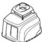
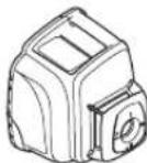
natural_image
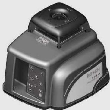
Exterior view of a Bosch industrial device with control panel and display (no visible text or symbols)Robert Bosch GmbH
Power Tools Division
70745 Leinfelden-Echterdingen
www.bosch-pt.com
1 609 929 L80 (2007.07) T / 420
BL 200 GC Professional

BOSCH
natural_image
Technical line drawing of a tripod-mounted surveying instrument with a hand holding a pole, showing motion and signal waves (no text or symbols)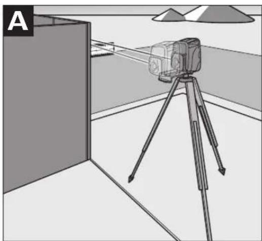
natural_image
Diagram of a surveying instrument on a tripod in an indoor setting, with no visible text or symbols.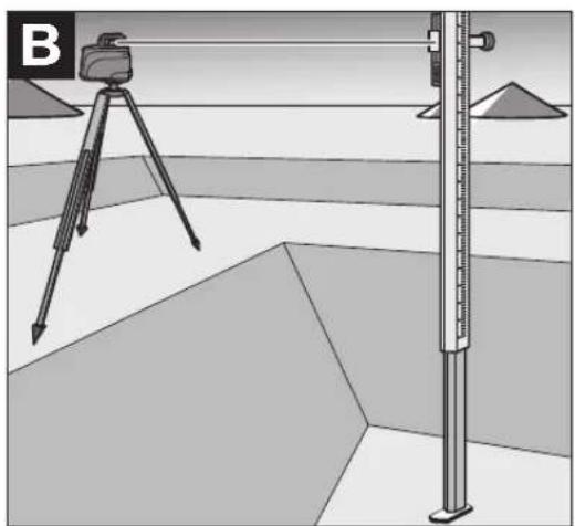
natural_image
Illustration of a surveying setup with a tripod-mounted instrument and a vertical scale, no text or symbols present1 609 929 L80 | (26.7.07) Bosch Power Tools


4 |
natural_image
Interior view of a room with window frames and a measuring tape, no text or symbols present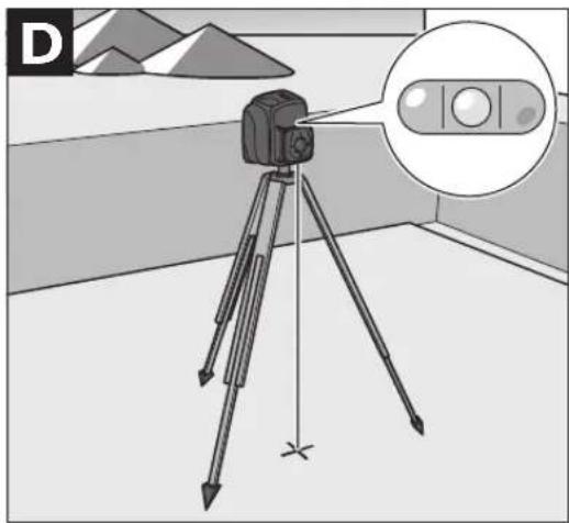
natural_image
Illustration of a surveying instrument on a tripod with a magnified inset showing a control panel (no text or symbols)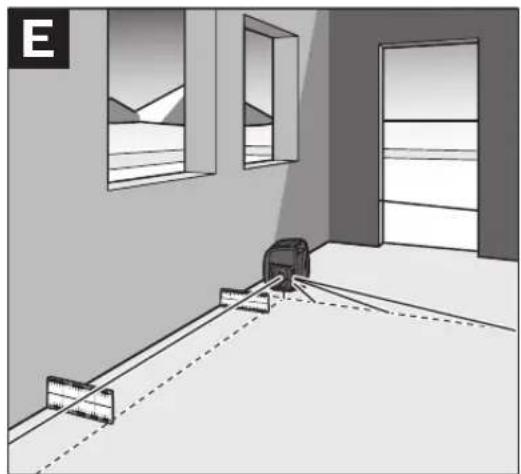
natural_image
Interior view of a room with window and door, showing a floor-mounted device and dashed lines indicating measurement or alignment (no text or symbols)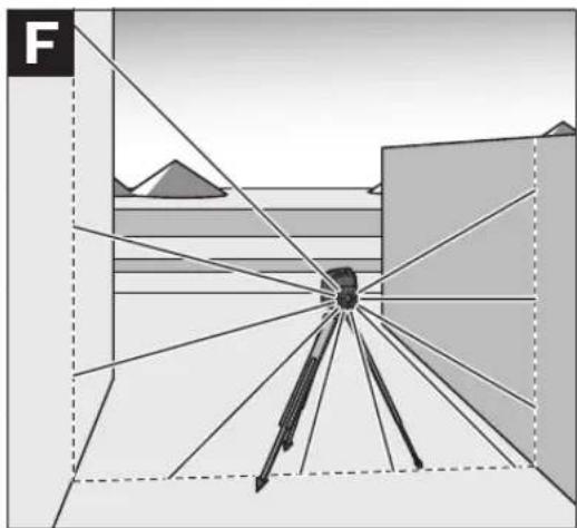
natural_image
Diagram of a surveying instrument on a tripod with geometric lines extending outward, no text or symbols present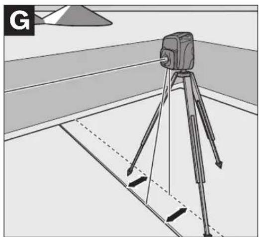
natural_image
Diagram of a surveying instrument mounted on a tripod with alignment lines, showing measurement setup (no text or symbols)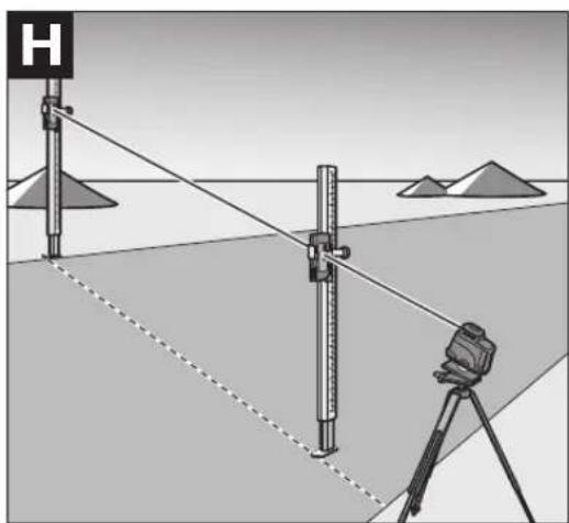
natural_image
Diagram of surveying measurement setup with tripod, ruler, and binoculars over a field (no text or symbols)1 609 929 L80 | (26.7.07) Bosch Power Tools


1 609 929 L80 | (26.7.07) Bosch Power Tools
2 607 224 908 (230 V, EU)
2 607 224 909 (230 V, UK)
2 607 224 910 (240 V, Australia)
1 609 203 M04
1 609 203 R54


Deutsch | 7
Sicherheitshinweise

natural_image
Pure geometric diagram with crosshair and circular shapes (no text or symbols)12 | Deutsch
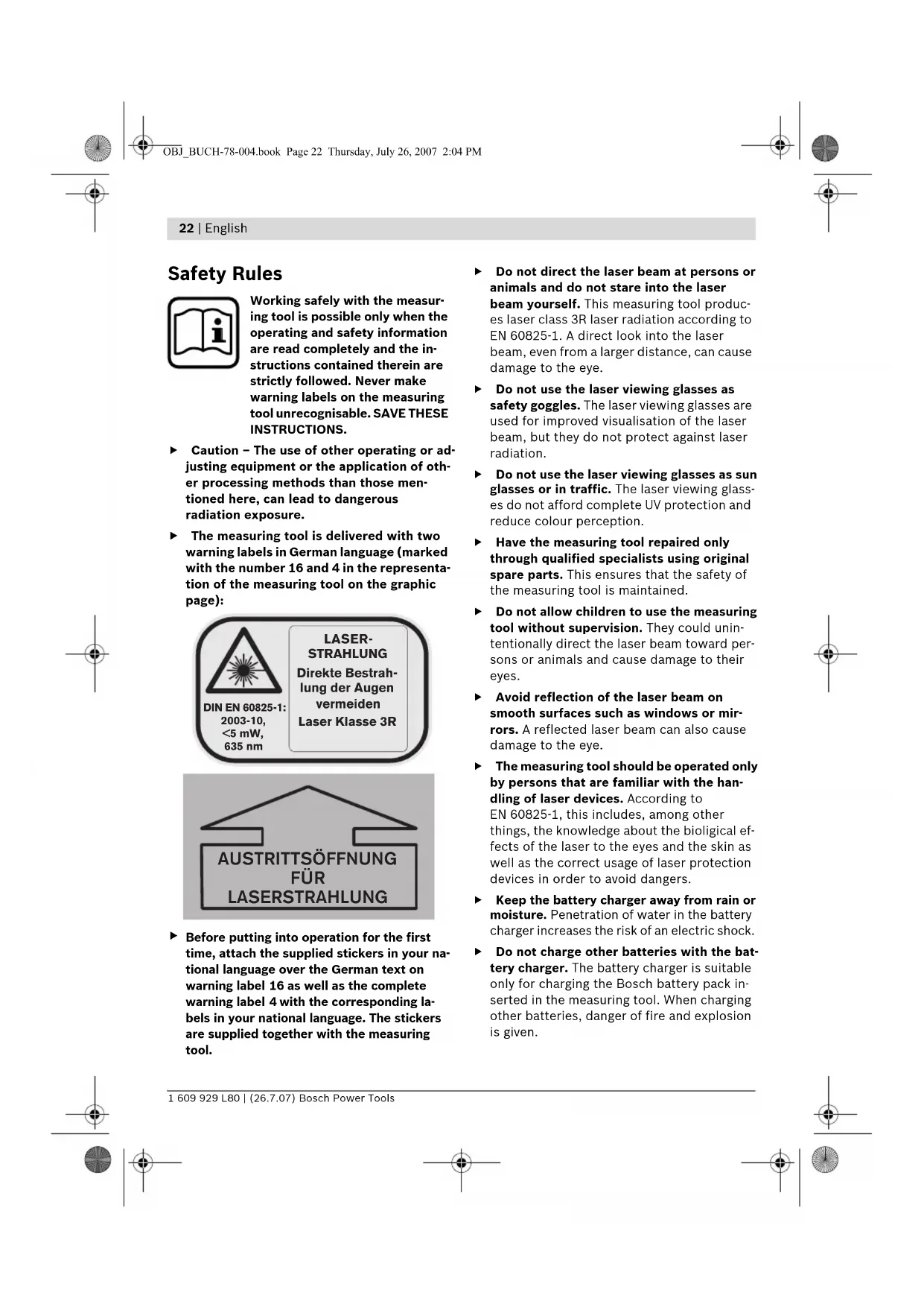
Working safely with the measuring tool is possible only when the operating and safety information are read completely and the instructions contained therein are strictly followed. Never make warning labels on the measuring tool unrecognisable. SAVE THESE INSTRUCTIONS.
- Caution – The use of other operating or adjusting equipment or the application of other processing methods than those mentioned here, can lead to dangerous radiation exposure.
The measuring tool is delivered with two warning labels in German language (marked with the number 16 and 4 in the representation of the measuring tool on the graphic page):
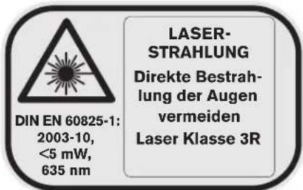

Before putting into operation for the first time, attach the supplied stickers in your national language over the German text on warning label 16 as well as the complete warning label 4 with the corresponding labels in your national language. The stickers are supplied together with the measuring tool.
Do not direct the laser beam at persons or animals and do not stare into the laser beam yourself. This measuring tool produces laser class 3R laser radiation according to EN 60825-1. A direct look into the laser beam, even from a larger distance, can cause damage to the eye.
▶ Do not use the laser viewing glasses as safety goggles. The laser viewing glasses are used for improved visualisation of the laser beam, but they do not protect against laser radiation.
Do not use the laser viewing glasses as sun glasses or in traffic. The laser viewing glasses do not afford complete UV protection and reduce colour perception.
▶ Have the measuring tool repaired only through qualified specialists using original spare parts. This ensures that the safety of the measuring tool is maintained.
Do not allow children to use the measuring tool without supervision. They could unintentionally direct the laser beam toward persons or animals and cause damage to their eyes.
▶ Avoid reflection of the laser beam on smooth surfaces such as windows or mirrors. A reflected laser beam can also cause damage to the eye.
The measuring tool should be operated only by persons that are familiar with the handling of laser devices. According to EN 60825-1, this includes, among other things, the knowledge about the biological effects of the laser to the eyes and the skin as well as the correct usage of laser protection devices in order to avoid dangers.
- Keep the battery charger away from rain or moisture. Penetration of water in the battery charger increases the risk of an electric shock.
Do not charge other batteries with the battery charger. The battery charger is suitable only for charging the Bosch battery pack inserted in the measuring tool. When charging other batteries, danger of fire and explosion is given.
▶ Keep the battery charger clean. Contamination can lead to danger of an electric shock.
Before each use, check the battery charger, cable and plug. If damage is detected, do not use the battery charger. Never open the battery charger yourself. Have repairs performed only by a qualified technician and only using original spare parts. Damaged battery chargers, cables and plugs increase the risk of an electric shock.
▶ Do not operate the battery charger on easily inflammable surfaces (e.g., paper, textiles, etc.) or surroundings. The heating of the battery charger during the charging process can pose a fire hazard.
▶ Under abusive conditions, liquid may be ejected from the battery; avoid contact. If contact accidentally occurs, flush with water. If liquid contacts eyes, additionally seek medical help. Liquid ejected from the battery may cause irritations or burns.
Functional Description
Please unfold the fold-out page with the representation of the measuring tool and leave it unfolded while reading the operating instructions.
Intended Use
The measuring tool is intended for projecting and checking precise horizontal partitions, vertical lines, building lines and plumb points, for both indoor and outdoor use.
Product Features
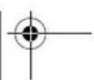
The numbering of the product features shown refers to the illustration of the measuring tool on the graphic page.
1 Spirit level
2 Reception lens for remote control
3 Socket for charge plug
4 Warning label, laser radiation exit opening
5 Exit opening for laser beam
6 Y-axis mark
7 X-axis mark
8 Plumb beam
9 Variable laser beam
10 Plumb notches, X-axis
11 Plumb notches, Y-axis
12 Latch of battery lid
13 Battery lid
14 Rubber foot
15 Battery pack
16 Laser warning label
17 Tripod mount, 5/8" (horizontal and vertical)
18 Serial number
19 Pushbutton for line operation and line length selection
20 Upper direction pushbutton
21 Left direction pushbutton
22 Pushbutton for rotational operation and selection of the rotation speed
23 Lower direction pushbutton
24 Right direction pushbutton
25 Manual levelling indicator "man"
26 Automatic levelling indicator "auto"
27 Battery charge control indicator
28 "man/auto" button for switching off the automatic levelling
29 On/Off button
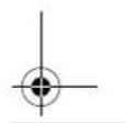
30 Construction laser measuring rod*
31 Laser viewing glasses
32 Wall holder/alignment unit*
33 5/8" screw on wall holder*
34 Knob screw of the alignment unit*
35 Measurement plate with stand
36 Ceiling measurement plate*
37 Inclination gauge*
38 High-performance receiver with holder
39 Remote control
40 Tripod*
41 Charge connector
42 Battery charger
43 Case
*The accessories illustrated or described are not included as standard delivery.


24 | English
Technical Data
| Laser Level BL 200 GC | |
| Professional | |
| Article number | 3 601 K15 000 |
| Working range (radius)1) | |
| - without receiver, approx. | 75 m |
| - with receiver, approx. | 200 m |
| Levelling accuracy1) 2) | ± 0.05 mm/m |
| Self-levelling range, typically | ± 8% (±5°) |
| Levelling duration, typically | 10 s |
| Rotational speed | 600/200/50/10 rpm |
| Operating temperature | -20 ... +50 °C |
| Storage temperature | -20 ... +70 °C |
| Relative air humidity, max. | 90 % |
| Laser class | 3R |
| Laser type | 635 nm, <5 mW |
| Laser beam ∅ at the exit opening, approx.1) | 8 mm |
| Tripod mount (horizontal and vertical) | 5/8" |
| Rechargeable batteries | 4 x 1.2 V KR20 (D) (5000 mAh) |
| Batteries (alkali-manganese) | 4 x 1.5 V L R 20 (D) |
| Operating life time, approx. | |
| - Rechargeable batteries | 30 h |
| - Batteries (alkali-manganese) | 40 h |
| Weight according to EPTA-Procedure 01/2003 | 3.0 kg |
| Dimensions | 211 x 180 x 190 mm |
| Degree of protection | IP 66 (dust-proof and protected against powerful water jets) |
1) at 21 °C
2) alongside the axes
Please observe the article number on the type plate of your measuring tool. The trade names of the individual measuring tools may vary.
The measuring tool can be clearly identified with the serial number 18 on the type plate.
Assembly
Charging/Replacing the Battery Pack Charging the Battery Pack
Before using for the first time, charge the supplied battery pack 15. The battery pack can be charged only when in the measuring tool and only with the battery charger 42 intended for this purpose.
Insert the charge connector 41 of the battery charger into the socket 3 and connect the battery charger to the power supply. The red indicator on the battery charger lights up during the charge procedure. Charging an empty battery pack requires approx. 7 hours.
The charge procedure is ended automatically. Therefore, disconnect the battery charger 42 from the power supply after the charging has taken place. The battery charger 42 and the battery pack 15 are protected against overcharging. A battery that is new or has not been used for a longer period does not develop its full capacity until after approx. 5 charging/discharging cycles. If the battery pack is empty, the measuring tool can also be operated off of the battery charger 42 when connected to a power supply. Switch the measuring tool off, charge the battery pack for approx. 10 min and then switch the measuring tool on again with the battery charger connected.
Practical Advice on Protection of the Battery Pack
Do not recharge the battery pack 15 after each use, as this will reduce its capacity. Recharge the battery pack only when the battery charge control indicator 27 flashes or lights up continuously.
A considerably reduced operating period after charging indicates that the battery pack is used up and must be replaced.
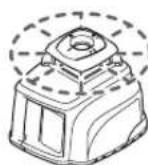
Replacing the Battery Pack
The supplied battery pack 15 can also be replaced against other rechargeable or alkali-manganese batteries. Use only batteries or rechargeable batteries of the same brand and with the same capacity. Always replace all of the rechargeable batteries/batteries together.
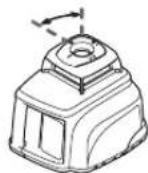
To remove the battery pack, turn the latch of the battery lid 12 to the position and take off the battery lid 13.
Insert either a new battery pack, batteries or other rechargeable batteries. When inserting, pay attention to the correct polarity. As a protective measure against incorrect polarity, the battery pack 15 can be inserted only in one position into the battery compartment.
In case other rechargeable batteries/batteries are inserted incorrectly the measuring tool cannot be switched on. Remove and reinsert the other batteries/rechargeable batteries ensuring correct polarity and wait for one minute until switching the measuring tool on again.
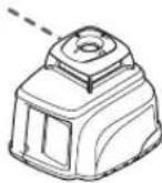
Reattach the battery lid 13 (only one position possible) and turn the latch 12 to the position.
A fuse ensures that only the battery pack 15 can be charged in the measuring tool. Other rechargeable batteries cannot be charged in the measuring tool.
Remove the battery pack, other rechargeable batteries or batteries from the measuring tool when not using it for long periods. When storing for extended periods, rechargeable batteries/batteries can corrode and discharge themselves.


26 | English
Operation
Initial Operation
- Avoid heavy impact or falling of the measuring tool. After heavy exterior impact on the measuring tool, an accuracy check should always be carried out before continuing to work (see "Levelling Accuracy").
▶ Do not subject the measuring tool to extreme temperatures or variations in temperature. As an example, do not leave it in vehicles for longer periods. In case of large variations in temperature, allow the measuring tool to adjust to the ambient temperature before putting it into operation.
Setting Up the Measuring Tool
Horizontal position
Vertical position
Set up the measuring tool on a sturdy surface in the horizontal or vertical position; mount it on a tripod 40 or to the wall holder with alignment unit 32.
Due to the high levelling accuracy, the measuring tool reacts sensitively to ground vibrations and position changes. Therefore, pay attention that the position of the measuring tool is stable in order to avoid operational interruptions due to re-levelling.
Switching On and Off
Do not direct the laser beam at persons or animals (especially not at their eye level) and do not stare into the laser beam yourself (not even from a distance). Immediately after switching on, the measuring tool emits the vertical plumb beam 8 and the variable laser beam 9, which rotates around the plumb beam. Special attention with the variable laser beam is required in point operation.
To switch on, press the On/Off pushbutton 29. The laser immediately starts in rotational operation, while the automatic levelling begins at the same time (see "Working with Automatic Levelling"). The indicators 25, 26 and 27 light up for three seconds. During further levelling, the automatic levelling indicator "auto" 26 flashes twice per second. When the levelling takes longer than 5 seconds, rotational operation is interrupted and the laser flashes twice per second until levelling is completed.
With the operating mode pushbuttons 19 and 22 as well as with the direction pushbuttons 20, 21, 23 and 24, the operating mode can already be set upon levelling-in (see "Operating Modes"). In this case, the measuring tool runs for 5 seconds in the selected operating mode during the levelling to confirm the entry. After the levelling, the function is continued in this operating mode.
The measuring tool is levelled-in when the laser beam and the "auto" indicator 26 light up continuously.
To switch off, press the On/Off 29 pushbutton again.
The measuring tool automatically switches off under the following conditions:
- When during automatic levelling, the measuring tool is not within the self-levelling range for more than 10 minutes, the device switches off to save the batteries. Reposition the measuring tool and switch on again.
- When exceeding the maximum permitted operating temperature of 50^ , the measuring tool switches off to protect the laser diode. After cooling down, the measuring tool is ready for operation and can be switched on again.
- When the self-check fails or in case of malfunctions during operation, all functions are blocked and the battery charge control indicator 27 flickers.
- When the measuring tool is not switched on again within 24 hours during activated stand by operation.
- When the battery voltage is too low.


Stand-by-operation with Storage of the Operating Mode
The measuring tool can be switched to stand by for a maximum of 24 hours. When the automatic levelling was activated ("auto" indicator 26 lights up continuously) prior to the beginning of the stand by operation, the automatic levelling continues to monitor the position of the measuring tool. The operating mode on the measuring tool is retained.
To activate stand by operation, press the line operation pushbutton 19 for at least 5 seconds. In stand by, the laser beam and the levelling indicators go out; only the battery charge control indicator 27 flashes once every 5 seconds.
To switch from stand by operation to normal operation, press the line operation pushbutton 19 again for at least 5 seconds. The measuring tool starts in the same operating mode as it was prior to the stand by. When the position of the measuring tool is changed as compared to the starting position prior to stand by, the automatic levelling reacts as if the out-of-level safety (see "Out-of-level Safety") were activated: Either the laser beam can be self-levelled to the same height as before the stand by or the laser beam is switched off as a protective measure against vertical errors.
Operating Modes
Overview
All three operating modes are possible with the measuring tool in horizontal and vertical position.
Rotational Operation
Rotational operation is especially recommended when working with the receiver 38. Four different rotation speeds can be selected.
Line Operation
In this operating mode, the variable laser beam moves within a defined aperture angle. This increases the visibility of the laser beam as when compared to rotational operation. Four different aperture angles are available.
Point Operation
In this operating mode, the best visibility of the variable laser beam is achieved. It is used, e.g., for easy projecting of heights or for checking building lines.
Course of X- and Y-axis
The X- and Y-axis are at a right angle to each other, in accordance with the marks 7 and 6 on the housing. The marks are exactly above the plumb notches 10 (X-axis) and 11 (Y-axis) at the bottom edge of the housing.
Making Use of the Operating Modes
Turning the Rotational Plane in the Vertical Position
When the measuring tool is in the vertical position, the laser point, the laser line or the rotational plane can be rotated around the Y-axis for basic sighting out or parallel alignment. For this, press the left 21 or right 24 direction pushbutton.
Rotation is only possible within the self-levelling range (8 % to the left or right). When the measuring tool reaches the limit of this range, a warning signal sounds, the laser and the "man" 25 and "auto" 26 indicators flash once per second. Either press the opposite direction pushbutton (21 or 24), or switch the measuring tool off in order to reposition it.

Rotational Operation
After switching on, the measuring tool is in rotational operation. It starts with the highest rotational speed.
By pressing the pushbutton for rotational operation 22, the speed can be reduced to a standstill (point operation) in four steps. Repeated pressing of the pushbutton 22 starts the rotational operation again at the highest speed.
When working with the receiver 38, it is recommended to select the highest rotational speed. When working without the receiver, reduce the rotational speed for improved visibility of the laser beam or use the laser viewing glasses 31 (accessory).


28 | English
When the measuring tool is in the vertical position and set to automatic levelling, it is possible to rotate the rotational plane around the X-axis by pressing the upper 20 or lower 23 direction push-button. Five seconds after last pressing on either of the four direction pushbuttons, the rotation plane is automatically levelled-in vertical again.
Line Operation
To switch to line operation, press the pushbutton for line operation 19. Depending on the previous operating mode, the measuring tool switches to point operation or to the line operation with the smallest aperture angle. Repeated pressing of the pushbutton 19 switches the measuring tool via the smallest aperture angle of 4° to the 30°, 60° and 180° aperture angles. At the same time, the speed is increased with each step. When pressing the pushbutton 19 again, the measuring tool returns to point operation.
Changing the Aperture Angle: When the measuring tool is in the horizontal position and set to automatic levelling, it is possible to increase or reduce the aperture angle by pressing the upper 20 or lower 23 direction pushbutton. The speed remains unchanged.
Rotating the Aperture Angle: When the measuring tool is in the horizontal position and set to automatic levelling or inclined operation in a single axis, it is possible to rotate the laser line or the laser point by 360° in steps by pressing the left 21 or right 24 direction pushbuttons. When the measuring tool is in the vertical position and set to automatic levelling, the rotation is actuated by pressing the upper 20 or lower 23 direction pushbuttons.
Point Operation
Point operation can be switched on either by pressing the pushbutton for rotational operation 22 or the pushbutton for line operation 19:
- When the measuring tool is set to rotational operation and the pushbutton for line operation 19 is pressed, then the measuring tool
starts with point operation. Exception: The measuring tool was already in point operation by having pressed the pushbutton for rotational operation 22. In this case, line operation immediately starts with the smallest aperture angle upon pressing the pushbutton for line operation.
- When the measuring tool is set to line operation and the pushbutton for rotational operation 22 is pressed, then the measuring tool also starts with point operation. Exception: The measuring tool was already in point operation by having pressed the pushbutton for line operation 19. In this case, rotational operation immediately starts with the highest rotational speed upon pressing the pushbutton for rotational operation.
Working with Automatic Levelling
Overview
After switching on, the measuring tool automatically detects the horizontal or vertical position. To change between the horizontal and vertical position, switch the measuring tool off, reposition it and switch on again.
After switching on, the measuring tool checks the horizontal and vertical position and automatically levels out any unevenness within the self-levelling range of approx. 8% (± 0.8 m/10 m).
When the measuring tool, after switching it on or after a position change, is out-of-level by more than 8 %, levelling in is no longer possible. As long as the out-of-level safety was not activated (see "Out-of-level Safety"), a slow-sequence warning signal sounds, the rotor is stopped, the laser beam and the "auto" 26 as well as the "man" 25 indicators flash once per second. In this case, switch the measuring tool off, realign it and then switch the measuring tool on again.
Position Changes
When the measuring tool is levelled in, it continuously checks the horizontal and vertical position. Position changes of the measuring tool lead to the following reactions:
Minor Position Changes
Minor position changes are compensated within 5 seconds. The selected operating mode is not interrupted. During the re-levelling, the "auto" indicator 26 flashes twice every second. This automatically compensates ground vibrations at the construction site or weather influences.
Major Positon Changes
When the measuring tool cannot carry out the levelling-in procedure within 5 seconds, the rotor is stopped, the laser beam and the "auto" indicator 26 flash twice per second to avoid faulty measurements during the levelling process.
Out-of-level Safety
The measuring tool has an out-of-level safety feature. It precludes levelling in after height changes exceeding 3 mm/m and thus prevents vertical errors. The out-of-level safety is switched on automatically 30 seconds after a pushbutton is pressed or after a levelling procedure. When the out-of-level safety is activated, the "auto" indicator 26 flashes once every 4 seconds.
After a position change, the measuring tool first attempts to compensate the change. When the limit value 3 mm/m is exceeded upon re-leveling, a fast-sequence warning signal sounds, the laser switches off and the "man" indicator 25 flashes twice every second. In this case, switch the measuring tool off and then on again. Then, check and correct the height of the laser beam.
Working without Automatic Levelling
In order to operate the measuring tool in any inclined position (see "Contouring Gradients"), the automatic levelling can be switched off for the X- and Y-axis.
▶ Position changes of the measuring tool are not detected when the automatic levelling is switched off.
Switching Off the Automatic Levelling in the Horizontal Position/Inclined Operation in a Single Axis
When the measuring tool is in the horizontal position, the automatic levelling for both axes is switched off by pressing the "man/auto" push-button 28 once. The "man" indicator 25 flashes once per second.
Repeated pressing of the "man/auto" pushbutton 28 switches on the inclined operation in a single axis. In inclined operation in a single axis, the X-axis is levelled in automatically, but the Y-axis is not. The "man" 25 and "auto" 26 indicators flash once per second.
When pressing the "man/auto" pushbutton 28 a third time, the automatic levelling is switched on again for both axes. The "auto" indicator 26 flashes (as long as the measuring tool is re-levelling) or lights up continuously (when the measuring tool is levelled in).
Switching Off the Automatic Levelling in the Vertical Position
When the measuring tool is in the vertical position, the automatic levelling for both axes is switched off by pressing the "man/auto" push-button 28 once. The "man" indicator 25 flashes once per second.
Repeated pressing of the "man/auto" pushbutton 28 switches the automatic levelling on again. The "auto" indicator 26 flashes (as long as the measuring tool is re-levelling) or lights up continuously (when the measuring tool is levelled in).


natural_image
Pure geometric diagram with crosshair and circular shapes (no text or symbols)30 | English
Changing the Inclination of the Rotational Plane
When the automatic levelling is switched off, the rotational plane (as well as the laser point or the laser line) can be rotated around the X- or the Y-axis with the direction pushbuttons. For this, the function of the four direction pushbuttons is independent of the horizontal or vertical position of the measuring tool and of the operating mode.
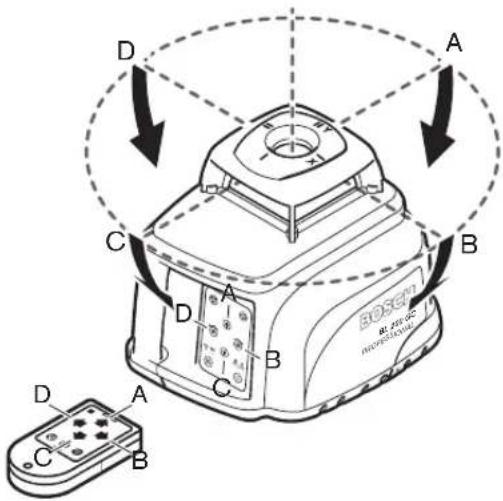
The rotational plane is rotated around the X-axis (directions A and C in the figure) with the upper 20 and lower 23 direction pushbuttons. The left 21 and right 24 direction pushbuttons rotate the rotational plane around the Y-axis (in directions D and B in the figure).
In inclined operation in a single axis (horizontal position), the rotational plane can be rotated around the X-axis with the upper 20 and lower 23 direction pushbuttons; rotation around the Y-axis is not possible.
Levelling accuracy
Influences on Accuracy
The ambient temperature has the greatest influence. Especially temperature differences occurring from the ground upward can divert the laser beam.
The deviations play a role in excess of approx. 20 m measuring distance and can easily reach two to four times the deviation at 100 m.
Because the largest difference in temperature layers is close to the ground, the measuring tool should always be mounted on a tripod when measuring distances exceeding 20 m. If possible, also set up the measuring tool in the centre of the work area.
Accuracy Check of the Measuring Tool
Apart from exterior influences, device-specific influences (such as heavy impact or falling down) can lead to deviations. Therefore, check the accuracy of the measuring tool each time before starting your work.
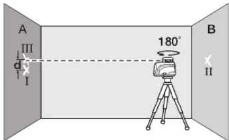
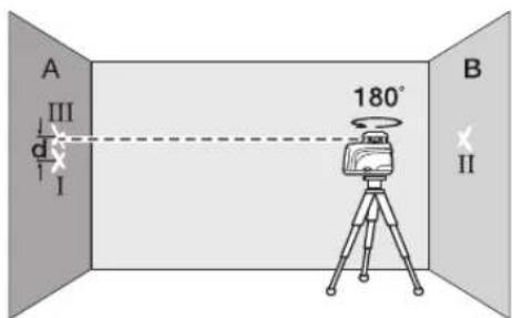
For the accuracy check, an unobstructed measuring distance of 20 m on firm ground between two walls A and B is required. With the measuring tool in the horizontal position, a – transit measurement is to be carried out across both axes X and Y (both positive and negative) (altogether 4 complete measurements).
- Mount the measuring tool in the horizontal position onto a tripod 40 (accessory) or place it on a firm and level surface near wall A. Switch the measuring tool on.


English | 31
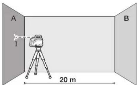
- After levelling, direct the laser beam in point operation onto the close wall A. Mark the centre point of the laser beam on the wall (point 1).
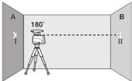
- Turn the measuring tool around by 180^ , allow it to level in and mark the centre point of the laser beam on the opposite wall B (point II).
- Without turning the measuring tool, position it close to wall B. Switch the measuring tool on and allow it to level in.
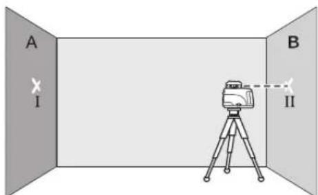
- Align the height of the measuring tool (using the tripod or by underlaying, if required) in such a manner that the centre point of the laser beam is projected exactly against the previously marked point II on wall B.
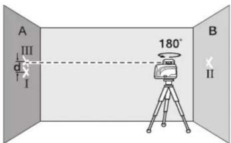
- Without altering the height, turn the measuring tool around by 180^ . Allow the measuring tool to level in and mark the centre point of the laser beam on the wall A (point III).
- The difference d of both marked points I and III on wall A amounts to the actual deviation of the measuring tool for the measured axis.
Repeat the measuring procedure for the other three axes. For this, turn the measuring tool prior to each measuring procedure by 90°.
On the measuring distance of 2 × 20 = 40 m , the maximum deviation may not exceed ± 2 mm . Consequently, the highest and lowest mark may not be further apart than 4 mm (maximum).
If the measuring tool should exceed the maximum deviation in anyone of the four measuring procedures, have it checked at a Bosch after-sales service agent.
Operating Instructions
▶ Always use the centre of the laser point for marking. The size of the laser point changes with the distance.
Laser viewing glasses (Accessory)
The laser viewing glasses filter out the ambient light. This makes the red light of the laser appear brighter for the eyes.
▶ Do not use the laser viewing glasses as safety goggles. The laser viewing glasses are used for better recognition of the laser beam and thus do not protect against laser radiation.
Do not use the laser viewing glasses as sun glasses or in traffic. The laser viewing glasses do not afford complete UV protection and reduce colour perception.


natural_image
Pure geometric crosshair symbols without any text or labels32 | English
Working with the Remote Control
While pressing the operator pushbuttons, the measuring tool can be brought out of alignment so that the rotation is briefly stopped. This effect is avoided when using the remote control 39.
Receiving areas for the remote control are located at the laser radiation outlet openings on four sides of the measuring tool as well as next to the socket for the charge plug 3.
The reception lens 2 at the bottom edge of the housing reacts to the remote control signals (typical working range: 200 m) with clearly increased sensitivity. When using the remote control, set up the measuring tool in such a manner that the signals of the remote control point directly at the reception lens 2.
Working with the Tripod (Accessory)
The measuring tool is equipped with two 5/8" tripod mounts 17, one for horizontal and one for vertical operation.
On a tripod 40 with a measuring scale on the elevator column, the height difference can be adjusted directly.
Working with Wall Holder/Alignment Unit (Accessory) (see figure A)
The measuring tool can also be mounted to the wall holder/alignment unit 32. For this, screw the 5/8" screw 33 of the wall holder into the tripod mount 17 for horizontal operation of the measuring tool.
Mounting to a wall: Mounting to a wall is recommended, e.g., for work above the elevation height of tripods or for work on unstable surfaces and without tripod. For this, fasten the wall holder 32, with the measuring tool mounted, as vertical as possible to a wall.
Mounting on a tripod: The wall holder 32 can also be screwed onto a tripod with the tripod mount on the back side. This method of fastening is especially recommended for work where the rotational plane is to be aligned with a reference line.
With the alignment unit, it is possible to move the mounted measuring tool vertically (when mounted to a wall) or horizontally (when mounted on a tripod) within a range of approx. 10 cm. For this, loosen the knob screws 34 on the alignment unit, move the measuring tool to the required position and tighten the knob screws 34 again.
Working with the Measuring Plate
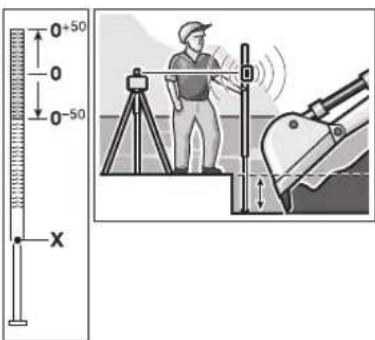
With the measuring plate 35, it is possible to project the laser mark onto the floor or the laser height onto a wall.
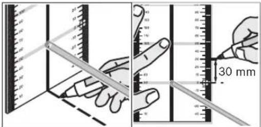
With the zero field and the scale, the offset or drop to the required height can be measured and projected at another location. This eliminates the necessity of precisely adjusting the measuring tool to the height to be projected.
The measuring plate 35 has a reflective coating that enhances the visibility of the laser beam at greater distances or in intense sunlight. The brightness intensification can be seen only when viewing, parallel to the laser beam, onto the measuring plate.
Working with the Measuring Rod (Accessory)
For checking evenness or projecting gradients, it is recommended to use the measuring rod 30 together with the receiver 38.
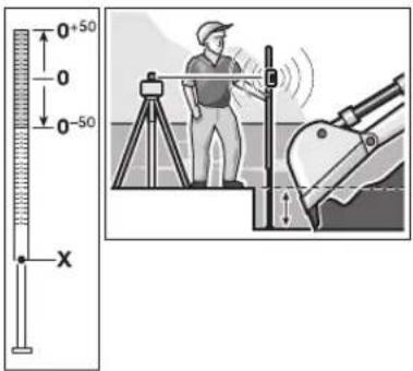
A relative millimeter scale ( ±50 cm) is marked on the top of the measuring rod 30. Its zero height (90 to 210 cm) can be preset at the bottom of the elevator column. This allows for direct reading of deviations from the specified height.


Work Examples
Note: For all work examples, with the exception of "Contouring Gradients", it is assumed that the automatic levelling is switched on.
Projecting Height Points (see figure B)
Position the measuring tool in the horizontal position onto a firm support or mount it onto a tripod 40 (accessory).
Working with tripod and receiver 38: In rotational operation, align the laser beam to the required height and project the height at the target location.
Working without tripod: Using the measuring plate 35, determine the height difference between the laser beam (in point or line operation) and the height line at the reference point. Rotate the laser beam with the left 21 and right 24 direction pushbuttons to the target location and project the measured height difference.
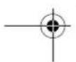
Parallel Aligning of a Plumb Beam (see figure C)
When right angles are to be projected or when partitions are to be aligned, the plumb beam 8 must be aligned parallel, meaning at the same distance to a reference line (e.g. a wall).
For this, set up the measuring tool in the vertical position and position it in such a manner that the plumb beam runs approximately parallel to the reference line.
For the exact positioning, measure the distance between the plumb beam and the reference line directly at the measuring tool, using the measuring plate 35. Now, measure the distance again between the plumb beam and the reference line with the distance as far as possible away from the measuring tool. Using the left 21 and right 24 direction pushbuttons, align the plumb beam in such a manner that it has the same distance to the reference line as measured directly at the measuring tool.
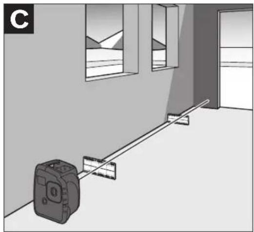
Centring a Rotational Plane over a Floor Point (see figure D)
When right angles are to be projected from a defined floor point, the rotational plane must be centred over this reference point.
Set up the measuring tool in the vertical position as close as possible over the reference point and select point operation.
Using the upper 20 and lower 23 direction push-buttons, rotate the variable laser beam in such a manner that it is pointed downward to the floor. With the spirit level 1 at the rotor head, align the laser beam exactly vertical.
▶ Make sure that the variable laser beam is pointed downward before viewing at the spirit level 1 from above. This will avoid looking directly into the laser beam.
Position the measuring tool in such a manner that the vertical laser beam precisely meets the reference point.
Projecting Right Angles (see figure E)
When the measuring tool is in the vertical position, the right angle is indicated by means of the plumb beam 8 and the variable laser beam 9.
If required, centre the rotational plane over a floor point and align the plumb beam 8 parallel to a reference line (e.g. a wall) in order to project right angles.
Marking Plumb Lines (see figure F)
Set up the measuring tool in the vertical position and align the variable laser beam 9 to the location at which the plumb line is to be marked. Select line or rotational operation and mark the plumb line.
Marking Vertical Planes (see figure F)
Set up the measuring tool in the vertical position. Bring the variable laser into alignment with a reference line (e.g. a partition). Select line or rotational operation and mark the vertical plane.

natural_image
Pure geometric diagram with crosshair and circular shapes (no text or symbols)34 | English
Parallel Aligning of a Rotational Plane (see figure G)
When the measuring tool is in the vertical position, the rotational plane can be aligned parallel to a reference line (e.g. a wall). For this, position the measuring tool as close as possible to the reference line and select rotational operation.
Align the rotational plane approximately parallel to the reference line. For this, rotate the rotational plane around the Y-axis using the left 21 and right 24 direction pushbuttons. For easier alignment, the rotational plane can be brought into proximity with the reference line. For this, incline the rotational plane around the X-axis using the upper 20 and lower 23 direction pushbuttons. Now, align the rotational plane exactly parallel to the reference line by rotating it around the Y-axis using the left 21 and right 24 direction pushbuttons. When no direction pushbutton is pressed for 5 seconds, the rotational plane is automatically aligned vertical again.
Projecting Plumb Points to the Ceiling
The plumb notches 10 and 11 are located at the bottom edge of the housing. They are used for precise alignment of the plumb beam above a floor point. Mark two right-angled auxiliary lines through the floor point. Set up the measuring tool in the horizontal position and bring it into alignment with the auxiliary lines using the plumb notches.
Working with tripod: When the measuring tool is in the horizontal position, the laser origin is located directly above the horizontal tripod mount. When using a tripod 40 (accessory), a plumb bob can be attached to the tripod fastening screw and used for alignment of the laser to the floor point.
Contouring Gradients (see figure H)
When contouring gradients, the automatic levelling must be switched off (see "Working without Automatic Levelling"). Afterwards, the measuring tool can be set up in any inclined position.
When contouring gradients in only one axis direction (e.g. hill flanks or slopes) and when the measuring tool is in the horizontal position, it is recommended to select inclined operation in a single axis – (see "Switching Off the Automatic Levelling in the Horizontal Position/Inclined Operation in a Single Axis"). In this case, align the measuring tool with the Y-axis parallel to the direction of the incline or slope.
For contouring of precise gradients, it is recommended to use an inclination gauge 37 (accessory) which is mounted onto a tripod 40.
It is also possible to align the measuring tool parallel to the required incline by underlaying on one side or with use of the tripod 40 (accessory). Within the self-levelling range of 8 %, inclines can also be adjusted with the direction pushbutons.


English | 35
Overview of Indications
| Laser beam | Rotation of the laser* | Warning signal | auto | man | - - + | |
| Switching on the measuring tool (3 s self-check) | ● | ● | ● | ● | ● | |
| Measuring tool levelled in/ready for operation | ● | ● | ● | |||
| Levelling in or re-levelling | 2x/1 s | ○ | 2x/1 s | |||
| Self-levelling range exceeded | 1x/1 s | ○ | 1x/1 s | 1x/1 s | 1x/1 s | |
| Out-of-level shutoff activated 1x/4 s | ||||||
| Out-of-level shutoff actuated | ○ | ○ | 4x/1 s | 2x/1 s | ||
| Automatic levelling switched off | 1x/1 s | |||||
| Inclined operation in a single axis is switched on | 1x/1 s | 1x/1 s | ||||
| Stand-by-operation with Storage of the Operating Mode | ○ | ○ | 1x/5 s | |||
| Battery voltage low | 1x/2 s | |||||
| Battery empty | ● | |||||
| Malfunction | ○ | ○ | ○ | ○ | ● | |
| * for line and rotational operation | ||||||
| 1x/1 s | Flashing frequency (e.g. once per second) | |||||
| ● | Continuous operation | |||||
| ○ | Function stopped | |||||
Maintenance and Service
Maintenance and Cleaning
Keep the measuring tool clean at all times.
Wipe away debris or contamination with a dry, soft cloth. Do not use cleaning agents or solvents.
Regularly clean the surfaces at the exit opening of the laser in particular, and pay attention to any fluff of fibres.
When heavily contaminated, the measuring tool can be cleaned under running water. Do not immerse the measuring tool in water and do not subject it to a high-pressure water jet.
If the measuring tool should fail despite the care taken in manufacturing and testing procedures, repair should be carried out by an authorized after-sales service centre for Bosch power tools.
In all correspondence and spare parts orders, please always include the 10-digit article number given on the type plate of the measuring tool.
Spare Parts
Rubber foot 14 (3 pce.) ..... 1 609 203 588
Battery lid 13....1 609 203 M02
Battery pack 15 ..... 1 609 203 M04
36 | English
After-sales service and customer assistance
Our after-sales service responds to your questions concerning maintenance and repair of your product as well as spare parts. Exploded views and information on spare parts can also be found under:
www.bosch-pt.com
Our customer consultants answer your questions concerning best buy, application and adjustment of products and accessories.
Great Britain
Robert Bosch Ltd. (B.S.C.)
P.O. Box 98
Broadwater Park
North Orbital Road
Denham
Uxbridge
UB 9 5HJ
Tel. Service: +44 (0844) 736 0109
Fax: +44 (0844) 736 0146
Australia, New Zealand and Pacific Islands
Robert Bosch Australia Pty. Ltd.
Power Tools
Locked Bag 66
Clayton South VIC 3169
Customer Contact Center
Inside Australia:
Phone: +61 (01300) 307 044
Fax: + 61 (01300) 307 045
Inside New Zealand:
Phone: +64 (0800) 543 353
Fax: +64 (0800) 428 570
Outside AU and NZ:
Phone: +61 (03) 9541 5555
www.bosch.com.au
Disposal
Measuring tools, accessories and packaging should be sorted for environmental-friendly recycling.
Only for EC countries:

Do not dispose of measuring tools into household waste!
According the European Guideline 2002/96/EC for Waste Electrical and Electronic Equipment and its implementation into national
right, measuring tools that are no longer usable must be collected separately and disposed of in an environmentally correct manner.
Battery packs/batteries:
Do not dispose of battery packs/batteries into household waste, fire or water. Battery packs/batteries should be collected, recycled or disposed of in an environmental-friendly manner.
Only for EC countries:
Defective or dead out battery packs/batteries must be recycled according the guideline 91/157/EEC.
Batteries no longer suitable for use can be directly returned at:
Great Britain
Robert Bosch Ltd. (B.S.C.)
P.O. Box 98
Broadwater Park
North Orbital Road
Denham
Uxbridge
UB 9 5HJ
Tel. Service: +44 (0844) 736 0109
Fax: +44 (0844) 736 0146
Subject to change without notice.


Français | 37
natural_image
Pure geometric diagram with crosshair and circular shapes (no text or symbols)44 | Français
natural_image
Pure geometric diagram with crosshair and circle shapes without any text or symbols48 | Français
Robert Bosch (France) S.A.S.
natural_image
Pure geometric diagram with crosshair and circle shapes without any text or symbols58 | Español
natural_image
Pure geometric diagram with crosshair and circle shapes without any text or symbols60 | Español
natural_image
Pure geometric diagram with crosshair and circular shapes (no text or symbols)62 | Español
natural_image
Pure geometric diagram with crosshair and circle shapes without any text or symbols72 | Português
natural_image
Pure geometric diagram with crosshair and circular shapes, no text or symbols present74 | Português
Mudanças de posição
natural_image
Pure geometric diagram with crosshair and circular shapes (no text or symbols)78 | Português
natural_image
Pure geometric diagram with crosshair and circle shapes without any text or symbols88 | Italiano
natural_image
Pure geometric diagram with crosshair and circular shapes (no text or symbols)90 | Italiano
natural_image
Pure geometric diagram with crosshair and circular shapes (no text or symbols)92 | Italiano
natural_image
Pure geometric diagram with crosshair and circular shapes (no text or symbols)106 | Nederlands
natural_image
Pure geometric diagram with crosshair and circular shapes (no text or symbols)108 | Nederlands
natural_image
Pure geometric diagram with crosshair and circular shapes, no text or symbols present110 | Nederlands
natural_image
Pure geometric diagram with crosshair and circular shapes (no text or symbols)112 | Nederlands
natural_image
Pure geometric diagram with crosshair and circular shapes (no text or symbols)118 | Dansk
natural_image
Pure geometric diagram with crosshair and circular shapes (no text or symbols)120 | Dansk
Trædesikring
Dansk | 123
natural_image
Pure geometric diagram with crosshair and circle shapes without any text or symbols126 | Dansk
Bosch Service Center
Telegrafvej 3
2750 Ballerup
Tel. Service Center: +45 (04489) 8855
Fax: +45 (04489) 87 55
E-Mail: vaerktoej@dk.bosch.com
Bortskaffelse
natural_image
Pure geometric diagram with crosshair and circle shapes without any text or symbols134 | Svenska
natural_image
Pure geometric diagram with crosshair and circular shapes, no text or symbols present152 | Norsk
natural_image
Pure geometric diagram with crosshair and circular shapes (no text or symbols)178 | Ελληνικά
natural_image
Pure geometric diagram with crosshair and circle shapes without any text or symbols194 | Türkçe
Bosch San. ve Tic. A.S.
Ahi Evran Cad. No:1 Kat:22
Polaris Plaza
80670 Maslak/Istanbul
natural_image
Pure geometric diagram with crosshair and circular shapes (no text or symbols)224 | Polski
Robert Bosch Sp. z o.o.
natural_image
Pure geometric diagram with crosshair and circle shapes without any text or symbols238 | Česky
natural_image
Pure geometric diagram with crosshair and circle shapes without any text or symbols250 | Slovensky
natural_image
Pure geometric diagram with crosshair and circular shapes (no text or symbols)252 | Slovensky
natural_image
Pure geometric diagram with crosshair and circular shapes, no text or symbols present254 | Slovensky
natural_image
Pure geometric diagram with crosshair and circular shapes (no text or symbols)284 | Русский
natural_image
Pure geometric diagram with crosshair and circular shapes (no text or symbols)316 | Română
Bosch Service Center
Str. Horia Măcelariu Nr. 30-34,
013937 Bucureşti
Tel. Service scule electrice: +40 (021) 4 05 75 40
Fax: +40 (021) 4 05 75 66
E-Mail: infoBSC@ro.bosch.com
Sa nultim poljem i skalom možete meriti odstupanje prema željenoj visini i ponovo nanositi na drugom mestu. Tako odpada tačno podešavanje mernog alata na visinu na koju se prenosi.
Merna ploča 35 ima refleksioni sloj koji poboljšava vidljivost laserskog zraka na većem rastojanju odnosno pri jačem sunčevom zračenju. Pojačavanje svetlosti se može samo onda prepoznati, ako gledate na mernu ploču paralelno laserskom zraku.


Radovi sa mernom letvom (pribor)
Za kontrolu ravnine ili nanošenje kosine preporučuje se merna letva 30 zajedno sa prijemnikom 38.