
RS 16 L S - Lamp STEINEL - Free user manual and instructions
Find the device manual for free RS 16 L S STEINEL in PDF.
| Product type | Motion sensor lamp |
| Power supply | 230-240 V, 50 Hz |
| Max power | 60 W (E27) |
| Detection technology | HF 5.8 GHz (continuous radar) |
| Detection range | 1 to 8 m (continuously adjustable) |
| Detection angle | 360° (angular opening 160°) |
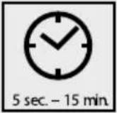
| Time delay | 5 s to 15 min (continuously adjustable) |
| Twilight threshold | 2 to 2000 lux (continuously adjustable) |
| Protection rating | IP44 |
| Protection class | II |
| Standby consumption | ~0.9 W |
| Mounting | Wall or ceiling (indoor) |
| Warranty | 3 years manufacturer |
| Compliance | CE, directive 2014/53/EU |
| Main functions | Motion detection, automatic lighting, range settings, time delay and twilight setting |
| Maintenance and cleaning | Clean with a soft, dry cloth, no abrasive products |
| Safety | Disconnect power before any intervention; installation by a professional (standard NF C-15100) |
| Spare parts and repairability | Accessories available from Steinel after-sales service |
| General information | Manufacturer: Steinel; Model: RS 16 L S |
Frequently Asked Questions - RS 16 L S STEINEL
User questions about RS 16 L S STEINEL
0 question about this device. Answer the ones you know or ask your own.
Ask a new question about this device
Download the instructions for your Lamp in PDF format for free! Find your manual RS 16 L S - STEINEL and take your electronic device back in hand. On this page are published all the documents necessary for the use of your device. RS 16 L S by STEINEL.
USER MANUAL RS 16 L S STEINEL
RS 10-1 L RS 100 L RS 16 L RS 16-2 L
natural_image
Plain white circular object with rounded edges, no visible text or symbolsRS 13 L
natural_image
Circular white ceiling light fixture with a recessed top (no text or symbols visible)RS 10-3 L RS 21 L RS 10 L
natural_image
Circular recessed ceiling light fixture with adjustable corners and mounting feet (no text or symbols)
natural_image
Plain white oval-shaped object with a subtle gradient, no text or symbols visible.
natural_image
Circular white ceiling light fixture with smooth surface and no visible text or symbolsRS 10-4 L RS 10-10 L RS 14 L RS 15 L
natural_image
Circular recessed light fixture with concentric rings (no text or symbols)
natural_image
Simple white dome-shaped object with a curved top surface (no text or symbols)
natural_image
Simple white ceiling light fixture with a curved glass rim (no text or symbols)
natural_image
Pure geometric shape with a circular cutout, no text or symbols visibleRS 10-5 L RS 10-6 L
natural_image
Abstract geometric design with a central circular element and surrounding diamond-shaped forms (no text or symbols)Information
RS Serie
Serie RS
RS 21 L

Serie RS

Serie RS
natural_image
Technical diagram showing a mechanical component with a circular cross-section and a 8-meter scale indicator (no text or symbols present)

natural_image
Technical diagram showing a mechanical component and its corresponding circular cross-section (no text or symbols)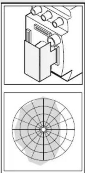
natural_image
Technical diagram showing a mechanical device and its corresponding circular grid pattern (no text or symbols)
natural_image
Technical diagram showing a mechanical assembly and a circular target-like pattern (no text or symbols)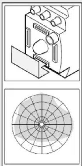
natural_image
Technical diagram showing a mechanical component and its corresponding circular cross-section (no text or symbols)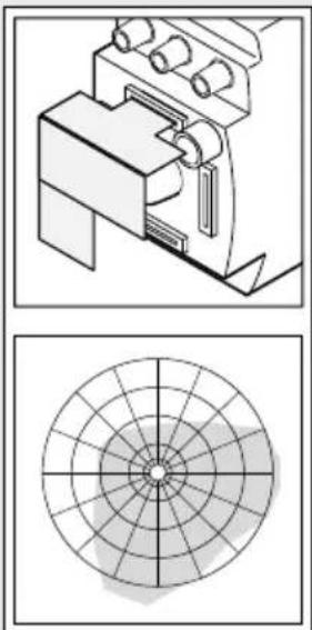
natural_image
Technical diagrams showing mechanical components and a circular target-like pattern (no text or symbols)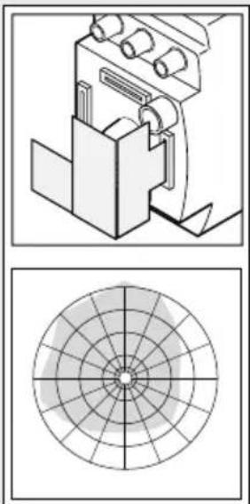
natural_image
Technical diagram showing a mechanical assembly and its corresponding circular cross-section (no text or symbols)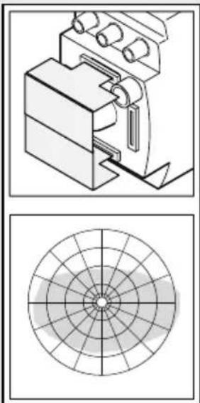
natural_image
Technical diagram showing a mechanical assembly and a circular target-like pattern (no text or symbols)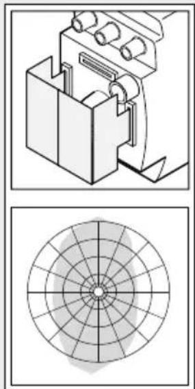
natural_image
Technical diagram showing a mechanical assembly and its corresponding circular cross-section (no text or symbols)Serie RS
| Tipp! |  Halogen Halogen | normal/not dimmable |
 | ||
 |  |  min. 5 min. min. 5 min. |
Installation
GB - Installation instructions
Dear Customer,
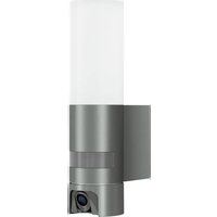
Congratulations on purchasing your new STEINEL SensorLight and thank you for the confidence you have shown in us. You have chosen a high-quality product that has been manufactured, tested and packed with the greatest care.
Please familiarise yourself with these instructions before attempting to install the SensorLight because prolonged reliable and trouble-free operation will only be ensured if it is fitted properly.
We hope your new STEINEL SensorLight will bring you lasting pleasure.
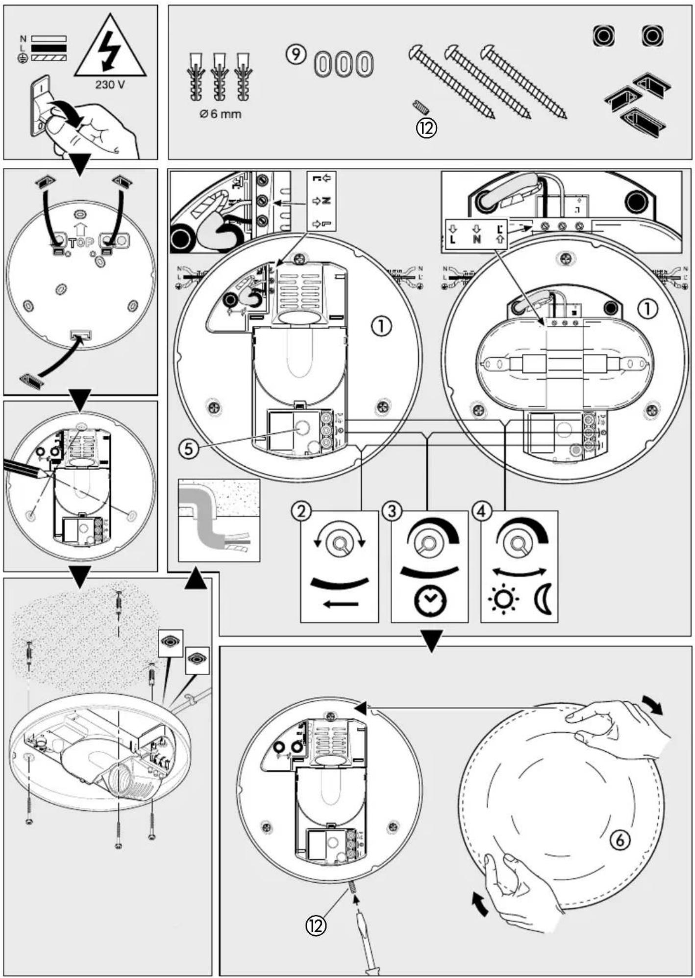
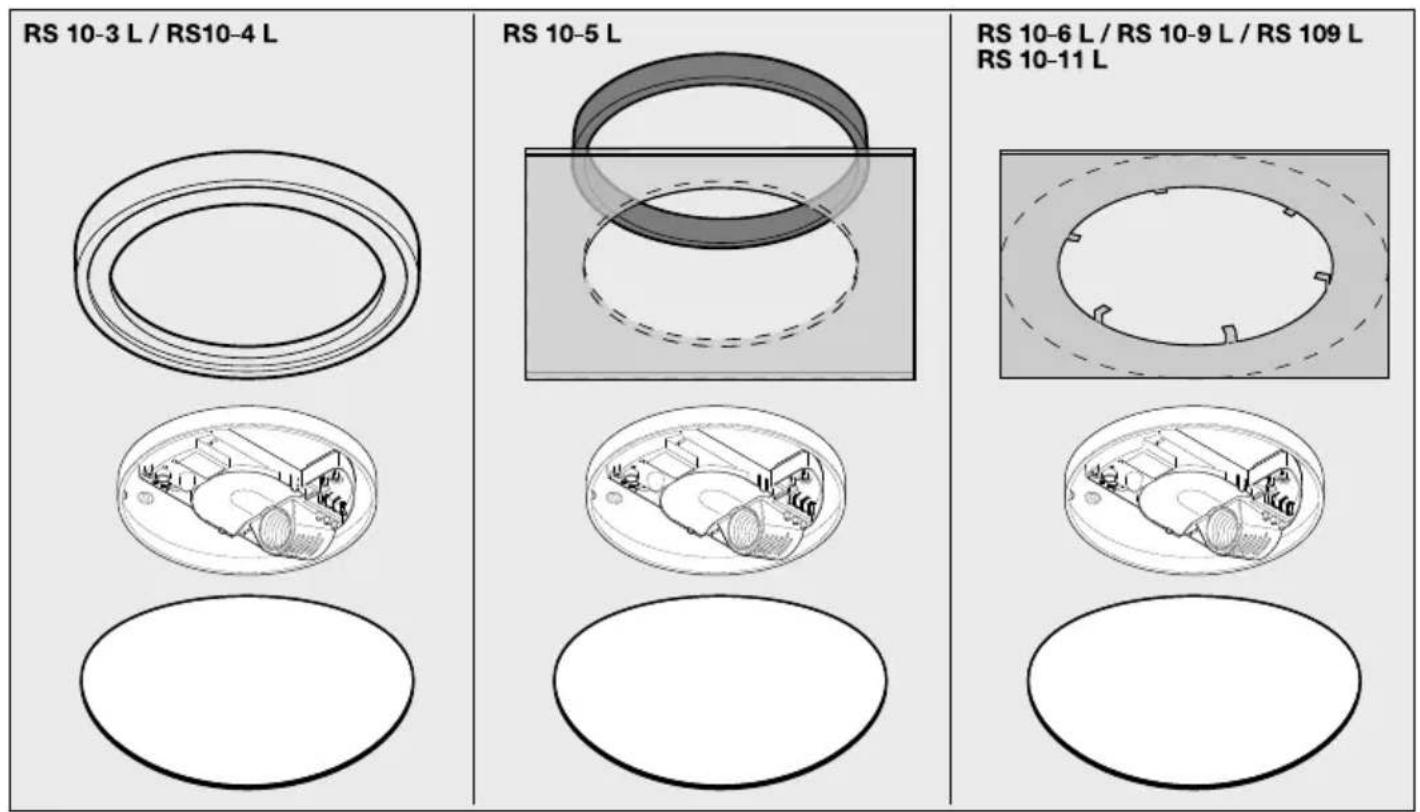
System components
① Enclosure
② Reach setting (1 - 8 m dia.)*
③ Time setting (5 sec. - 15 min.)
④ Twilight setting (2 - 2000 lux)
⑤ HF sensor
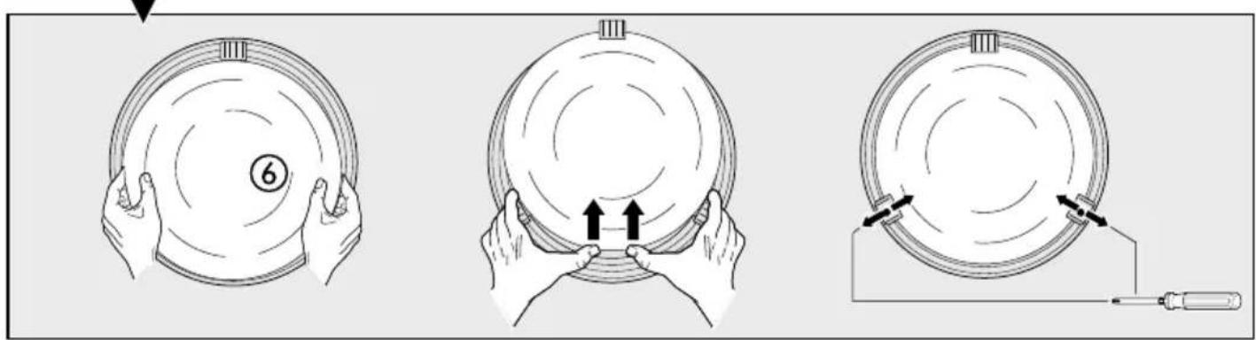
⑥ Glass shade
⑦ Glass shade clips (screw-fastenable)
⑧ Spring clip
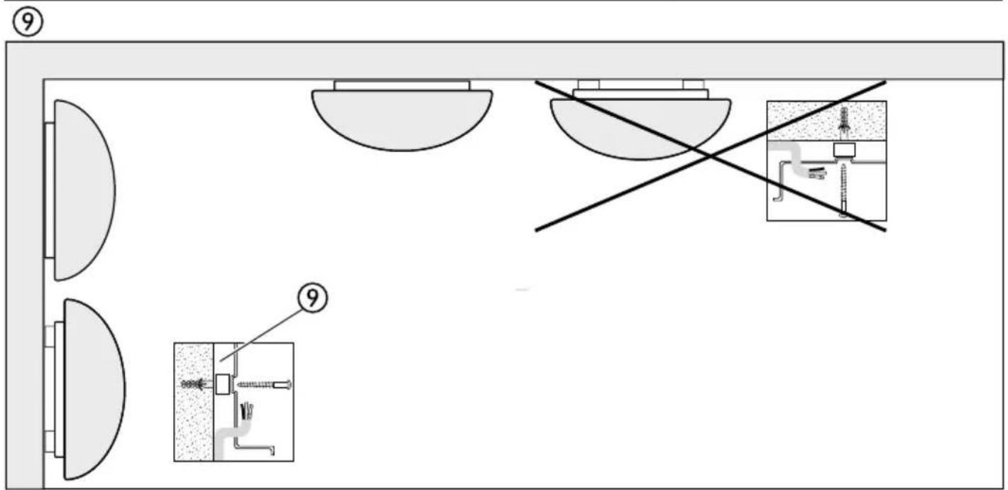
⑨ Spacers for surface wiring
⑩ Metal shrouds (not for RS 16, RS 16-2, RS 16-3, RS 15 L)
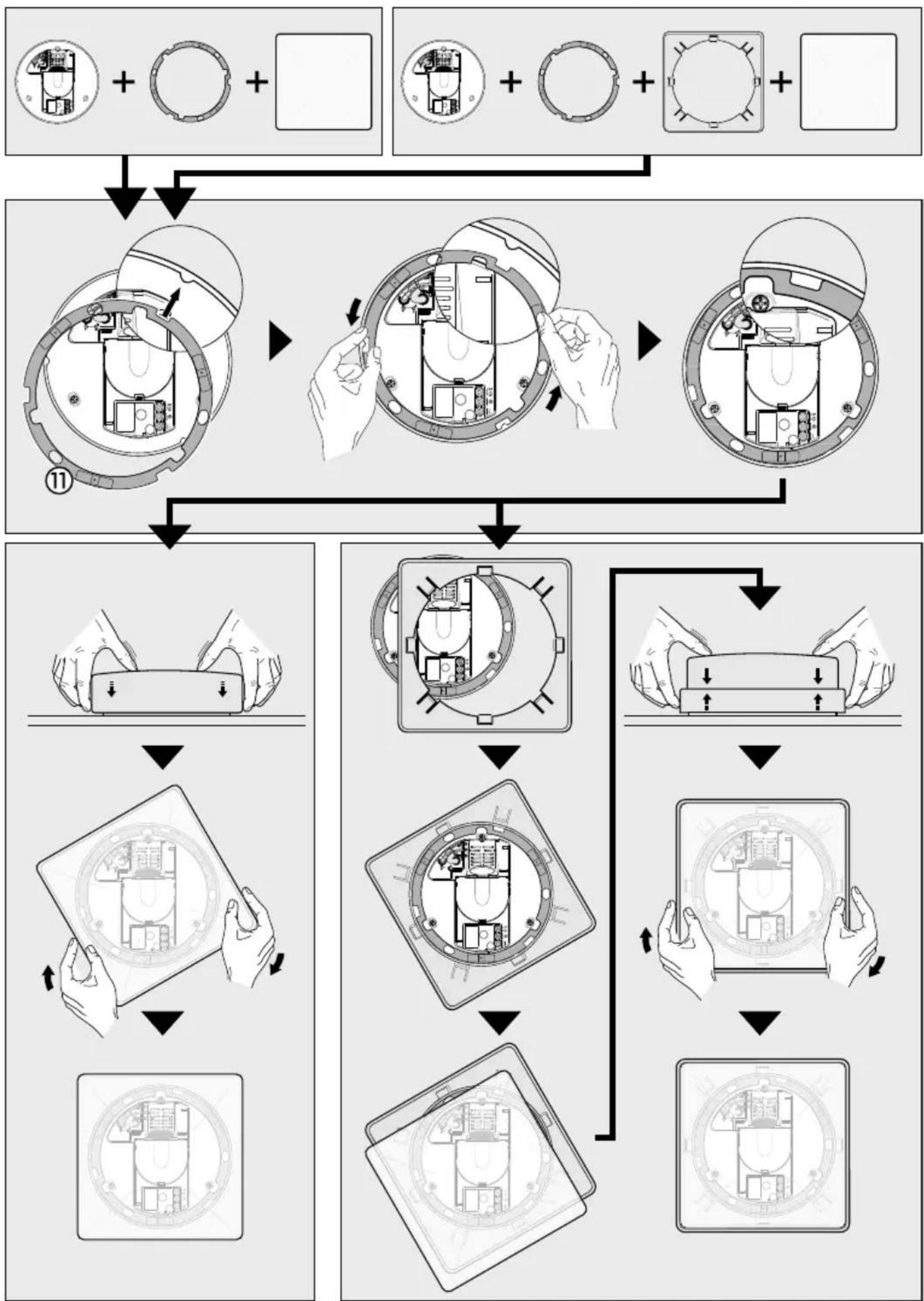
⑪ Snap ring for adjusting square glass shades
⑫ Glass shade locking screw (optional)

Safety warnings
■ Disconnect the power supply before attempting any work on the unit.
■ The electrical connection lead must be dead during installation. Therefore, switch off the power first and check that the circuit is dead using a voltage tester.
■ Installing the SensorLight involves work on the mains voltage supply. This work must therefore be carried out by a specialist in accordance with the applicable national wiring regulations and electrical operating conditions. (DE: VDE 0100, AT: ÖVE / ÖNORM E8001-1, CH: SEV 1000)
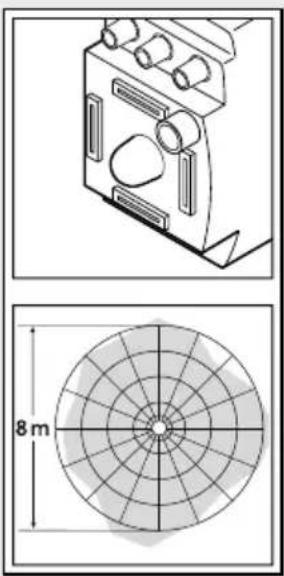
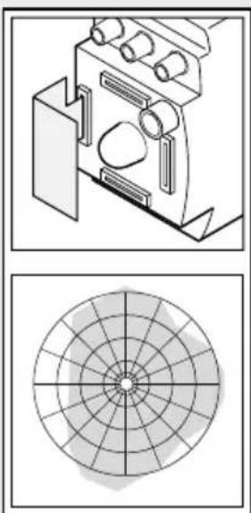
Principle
The SensorLight is an active motion detector. The integrated HF sensor emits high-frequency electromagnetic waves (5.8 GHz) and receives their echo. The sensor detects the change in echo from even the slightest movement in the light's detection zone. A microprocessor then triggers the "switch light ON" command. Detection is possible through doors, panes of glass or thin walls.
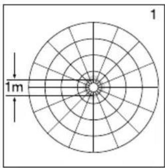
Detection zones for ceiling mounting:
1) Minimum reach (1 m dia.)*
2) Maximum reach (8 m dia.)*
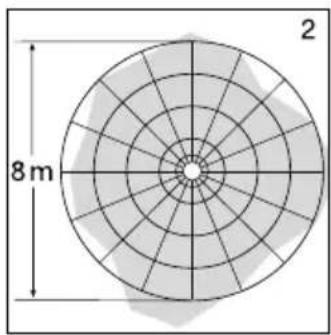
Detection zones for wall mounting:
3) Minimum reach (1 m dia.)*
4) Maximum reach (8 m dia.)*
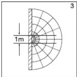
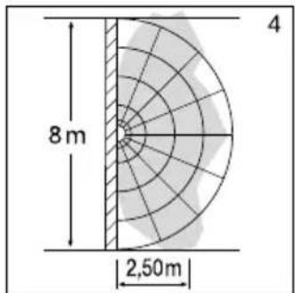
Important: Persons or objects moving towards the light are detected best.
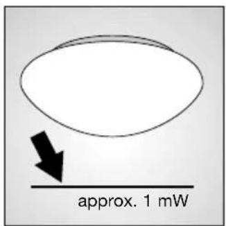
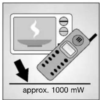
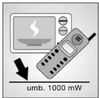
Note:
The high-frequency output of the HF sensor is approx. 1 mW – that's just 1,000th of the transmission power of a mobile phone or microwave oven.
Installation
Important: Make sure the installation site is not subject to vibration.
Connecting a dimmer will result in damage to the SensorLight.
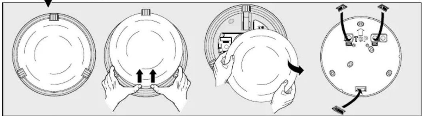
Installation procedure:
Before mounting the RS 21 L on the wall or ceiling, first fit the glass shade clips and adjust the glass shade (refer to drawing on page 3).
- Hold enclosure ① against the wall/ceiling and mark drill holes, paying attention to any existing wiring in the wall/ceiling.
- Drill the holes, insert wall plugs (6 mm dia.).
- Fit and pierce sealing plug for mains supply lead.
- Pass power supply leads through.
- Screw enclosure ① into place.
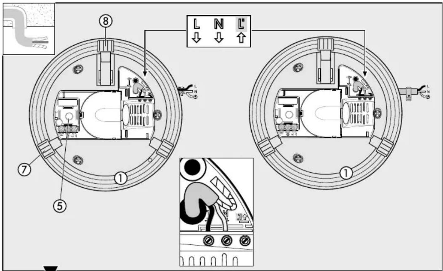
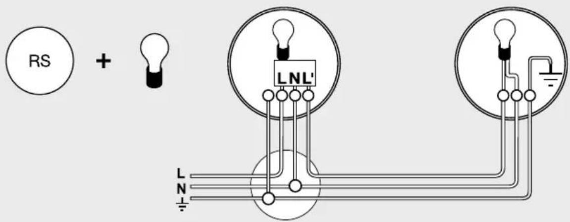
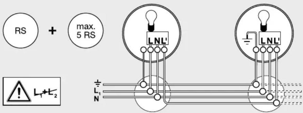
- Connecting the mains power supply lead (see fig.). The mains power supply lead is a 3-core cable:
L = phase (mostly black, brown or grey)
N = neutral conductor (usually blue)
PE = protective earth conductor (green/yellow)
If you are in any doubt, identify the conductors using a voltage tester; switch off the current again. Connect the phase conductor (L) and neutral conductor (N) to the terminal block.
Important: Reversing the connections will result in a short-circuit in the light unit or in your fuse box later on. In this case, you must identify the individual conductors once again and re-connect them. A mains switch for switching the unit ON and OFF may of course be installed in the mains power supply lead.
- Set functions ②, ③, ④.
- Fit glass shade and secure in place either by turning or by means of the spring clips (RS 21 L).
Wall mounting, mains power supply lead, surface wiring ⑨
Wall mounting with surface wiring can be carried out as shown in the diagram on page 7.
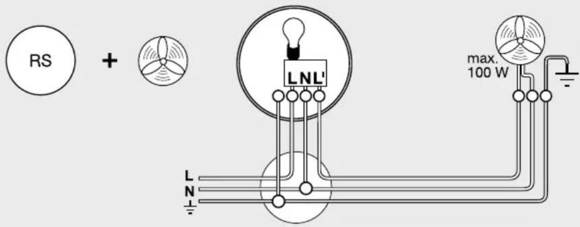
Connection of an additional load
An additional load (100 VA maximum, e.g. bathroom/WC fan extractor) may be connected to the SensorLight and will then be switched on and off by the sensor light's electronics. Screw the load's live conductor to the terminal marked L'. First remove the protective cap with a pair of pliers. The cables must also be fitted with the heat-resistant wire insulator. Loop neutral conductor (N) as well as any protective earth conductor (PE) through from the distribution box. (see wiring diagram on page 4)
Technical specifications
| Wattage: | RS 10/10-x/13/21 L: 60 W/E 27 max. |
| RS 14 L: 60 W/E 27 max. | |
| RS 15/16/16-x L: 60 W/E 27 max. | |
| RS 100/103 L: 60 W/E 27 max. | |
| RS 104 - 110 L: 2 x 30 W/G 9 max. | |
| plus 800 VA max. (resistive load, e.g. filament bulb) | |
| plus 100 VA max. (e.g. bathroom/WC fan extractor) | |
| Connection: | 230 – 240 V, 50 Hz |
| Installation site: | indoors, wall/ceiling mounting |
| HF system: | 5.8 GHz CW radar, ISM band |
| Transmission power: | approx. 1 mW |
| Detection: | 360°, 160° opening angle, if necessary through glass, wood and stud walls |
| Reach: | 1 – 8 m dia., infinitely variable |
| 3 – 8 m dia. (RS 15 L, RS 16/16-2/16-3 L) | |
| Time setting: | 5 sec. to 15 min. |
| Twilight setting: | 2 – 2000 lux |
| Enclosure: | IP 44 (IP 20 RS 21 L) |
| Protection class: | II |
| Power consumption: | approx. 0.9 W |
Functions
The SensorLight can be put into operation as soon as the enclosure ① has been fitted and the SensorLight has been connected to the mains power supply. Putting the light into operation manually at the light switch turns it off after 10 secs. for the calibration phase. Once calibrated, it is activated for the sensor mode. It is not necessary to operate the light switch a second time.
Reach setting (sensitivity)
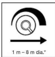
Reach is the term used to describe the diameter of the more or less circular detection zone produced on the ground after mounting the sensor light at a height of 2.5 m. Turn the reach control ② fully anticlockwise to select minimum reach (approx. 1 m
dia.)*, and fully clockwise to select maximum reach (approx. 8 m dia.)*. (The light leaves the factory set to maximum reach.)
Time setting (switch-off delay)
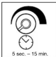
The light can be set to stay ON for any period of time between approx. 5 sec. (control ③ turned fully anticlockwise) and a maximum of 15 min. (control ③ turned fully clockwise). (The light leaves the factory set to the shortest time.) Any movement detected before this time elapses will re-start the timer. It is recommended to select the shortest time for adjusting the detection zone and for performing the walk test.
Note: After the light switches OFF, it takes approx. 1 sec. before it is able to start detecting movement again. The light will only switch on in response to movement once this period has elapsed.
Twilight setting (response threshold)

The chosen light response threshold can be infinitely varied from approx. 2–2000 lux. Turn control ④ fully anticlockwise to select dusk-to-dawn operation at about 2 lux. Turn control ④ fully clockwise to select daylight operation at about 2000 lux.
(The light leaves the factory set to daylight operation.) The control must be turned fully clockwise when adjusting the detection zone and performing the walk test in daylight.
CE Declaration of conformity
Hereby, STEINEL Vertrieb GmbH declares that the radio equipment type RS is in compliance with Directive 2014/53/EU. The full text of the EU declaration of conformity is available at the following internet address: www.steinel.de
Disposal
Electrical and electronic equipment, accessories and packaging must be recycled in an environmentally compatible manner.
Do not dispose of electrical and electronic equipment as domestic waste.
EU countries only:
Under the current European Directive on Waste Electrical and Electronic Equipment and its implementation in national law, electrical and electronic equipment no longer suitable for use must be collected separately and recycled in an environmentally compatible manner.
Manufacturer's warranty
This STEINEL product has been manufactured with great care, tested for proper operation and safety in accordance with applicable regulations and then subjected to random sample inspection. STEINEL guarantees that it is perfect condition and proper working order. The warranty period is 36 months, starting on the date of sale to the consumer. We will remedy defects caused by material flaws or manufacturing faults. The warranty will be met by repair or replacement at our own discretion. The warranty shall not cover damage to wear parts, damage or defects caused by improper treatment or maintenance. Further consequential damage to other objects is excluded.
Claims under the warranty will only be accepted if the unit is sent fully assembled and well packed complete with a brief description of the fault, a receipt or invoice (date of purchase and dealer's stamp) to the appropriate Service Centre.
Repair Service:
Our Customer Service Department will repair faults not covered by warranty or after the warranty period. Please send the product well packed to your nearest Service Centre.

Troubleshooting
| Malfunction | Cause Remedy | |
| SensorLight without power | ■ House fuse faulty, not switched ON, break in wiring■ Short circuit in mains power supply lead■ Any mains switch OFF | ■ Renew house fuse, switch ON mains power switch, check wiring with voltage tester■ Connect connections■ Switch on mains power switch |
| SensorLight will not switch ON | ■ Wrong twilight setting selected■ Bulb faulty■ Mains switch OFF■ House fuse faulty | ■ Adjust setting■ Change bulb■ Switch ON■ Renew house fuse, check connection if necessary |
| SensorLight will not switch OFF | ■ Continuous movement in the detection zone | ■ Check zone setting |
| SensorLight switches on without any identifiable movement | ■ Light mounting surface is subject to vibration■ Movement occurred, but not identified by the sensor (movement behind wall, movement of a small object in immediate lamp vicinity etc.) | ■ Securely mount enclosure■ Check zone setting |
| SensorLight does not switch ON despite movement | ■ Rapid movements are being suppressed to minimise malfunctioning or the detection zone you have set is too small | ■ Check zone setting |
FR - Instructions de montage
Cher client,
Installatie
Installazione
Installation
Installasjon
Pomembno: Najsigurnejše zaznavanje premikanja dosežete, će se premikate v smeri namontirane svetilke.
Opozorilo:
Inštalacija
Paigaldamine
natural_image
World map silhouette in grayscale, showing continents and oceans without any text or labelsContact
www.steinel.de/contact


- Serie RS
- Installation
- GB - Installation instructions
- Dear Customer,
- System components
- Safety warnings
- Principle
- Detection zones for ceiling mounting:
- Detection zones for wall mounting:
- Note:
- Installation procedure:
- Wall mounting, mains power supply lead, surface wiring ⑨
- Connection of an additional load
- Functions
- Reach setting (sensitivity)
- Time setting (switch-off delay)
- Twilight setting (response threshold)
- CE Declaration of conformity
- Disposal
- EU countries only:
- Manufacturer's warranty
- Repair Service:
- FR - Instructions de montage
- Installatie
- Installazione
- Installasjon
- Opozorilo:
- Inštalacija
- Paigaldamine
- Contact
Brand : STEINEL
Model : RS 16 L S
Category : Lamp