BL 980 R - Blower STIGA - Free user manual and instructions
Find the device manual for free BL 980 R STIGA in PDF.
| Brand | Stiga |
| Model | BL 980 R |
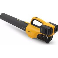
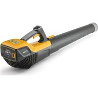
| Product type | Handheld blower |
| Power source | 2-stroke internal combustion engine, gasoline/oil mixture (40:1) |
| Recommended fuel | Unleaded gasoline with octane rating ≥ 90 |
| Recommended oil | Synthetic 2-stroke oil, JASO FC standard minimum |
| Tank capacity | Not specified in the manual (estimated 0.5 L) |
| Starting | Easy-Start system with manual recoil starter |
| Main functions | Blowing leaves, grass, and light debris |
| Controls | Throttle lever, speed regulator, engine stop, choke, primer |
| Included accessories | Blower tube, shoulder harness, tightening wrench |
| Routine maintenance | Air filter cleaning every 8-10 hours, spark plug check every 10 hours |
| Spark plug replacement | Every 100 hours of operation |
| Safety | Engine stop via STOP lever, protection against debris, spark plug kill switch |
| Noise level | High, requires hearing protection (value not specified) |
| Vibrations | Damping system on support plate |
| Intended use | Amateur use, domestic gardening |
| Warranty | Manufacturer's warranty against material and manufacturing defects |
Frequently Asked Questions - BL 980 R STIGA
User questions about BL 980 R STIGA
0 question about this device. Answer the ones you know or ask your own.
Ask a new question about this device
Download the instructions for your Blower in PDF format for free! Find your manual BL 980 R - STIGA and take your electronic device back in hand. On this page are published all the documents necessary for the use of your device. BL 980 R by STIGA.
USER MANUAL BL 980 R STIGA
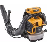
EN Back-pack powered blower
OPERATOR'S MANUAL
WARNING: read thoroughly the instruction booklet before using this machine.
Pa3dyByBaOT 3a rpaHnH co MOTop Ha BHaTpeHNO corOpyBaHe
HOJUTo CE HOCn Ha pAMEHnC
YNATCTBA 3A YNOTPEBA
BHIMAHHE: nped da ja ynotpe6nte MaunHata, BHIMaTeBhONpOHTaTe ro ynATCTBOTO 3a ynoTpe6a.

MANUAL DE INSTRUCTIUNI
ATENTIE: inainte de a utilizesmaina, cititi cu atentie manualul de fata.

CaoBaB Bo3DyXoYbHa C DnRaTeJem BHyTpeHHeRo cropaHnC HAnLeuHbIMn peMHAMN
PYKOBODCTBO NO 3KCNJYATAUIN
BHIMAHNE:IpeJe Yem noJIb3OBaTbc8 o6OpyOBoHHem,BHIMATEJIbHO IpoUHTte 3TO pyKOBoDCTBO nO 3HCnJIyatau.

Záhradny fukac s motorom svútornym spal'ovanim, nesený na ramene
NAVOD NA POUZITIE
UPOZORNENIE: pred pouzitim stroja si pozorne precitajte unto navod.

6. USO DELLA MACCHINA
Bcnuyn yka3aHnra "npedeH",3aJeH, "Decen" n "IaB" ce OTHacr Do pa60thaTnO3nua Ha onepaTopa.
1.2 CnPABKN
1.2.1 Φιγρη
ФИгурптЕВTe3n INHCTpyKUIN 3a
eKcIIOaTauJca HOMepuPAnH1,2,3,N T.H.
KOMnoHENTte NocOueHn HaФИгурптEc
OT6eJIa3aHn C6yKBnTeA,B,CnT.H.
CnpabKaTa 3a KOMnoHEnTa CHa
ФИгура2ce NocOuBa CHaJnCa:"Bx.
ФИr.2.C" nI npocTo "(ФИr.2.C)".
ФИгурптEc anHdNkATNBn.DeIcTBnTeJIHnTe
Yactn MoKe Da ce pa3JIuYabAT OT Te3n,
KoNTO ca nOKa3aHn HaФИгypaTa.
1.2.2 3arlabna
PbKOBOcTOe pa3dJeHo Ha rIaBn I npapraΦn. 3arIaBHeTo ha naparpaΦ "2.1 O6yehne" e no3aIabNe Ha "2. IpaBnla 3a 6e3onacHocT". OTHacHnraTo do 3aIaBn I nn npapraΦn ca OT6eJ3aHn CbC cbKpaSeHneTo "rI." IIN "nap." n CbOTBeTHn Homep. HanpImep: "rI. 2" IIN "nap. 2.1".
2. ПРавILA 3A БЕЗОПАСHОCT
2.1 OByeHne
Pa3yyeH n CBHHeTe c HOMaHdnte N C NOxOJaTO H3NoJ3BaHe Ha MaunHaT. HayeTe ce da n3KnIOvBaTe 6bp30 MaunHaT. HeCna3BaHeTo Ha npedynpexKeHnraTa n NHCTpyKuNTe MOHe da npuyHHn HHnDeHTn H/ Hn cepno3HN HapaHbAHn.
- HnKora He nO3BoJBaIe MaunHaTa da 6bDe n3PON3BaHa OT Deca NJIH OT Xopa, KOHTo He ca 3aNO3HaTn DOCTaTBuHO C INCTpyKUnTe. MecTHnTe 3aKOH MoKe Da npEdbNJaT MnHMaJIHa Bb3pAcT 3a npaBO Ha n3PON3BaHe.
-Да He ce n3noJ3Ba HNKORA MaunHaTa, aKO NOTpe6nteIe yMOpEn NnHepa3noJIOKeH, INe epneJ IeKapCTBa, hapKOTnU, aIKOXOIN BPeDn 3a peΦJIeKcNTe IN BHIMaHNeTO My BeueCTBa.
He 3a6paBnTe, ye onepaTOpt nIN To3n, KOHTO n3IOJ3Ba MaunHaTa e OTROBOpeH 3a INuIeHTN n He npEeDBnDEHN CNTyaUIn, KOHTO MORaT da ce clyuat Ha dpyrN Xopa Hn HA TExHa Co6CTBeHoCT. YAcT O TROBOPHOCTTA Ha Notpe6nte r pneueHKaTa Ha Bb3MOXHnTe PnCKOBe Ha TepeHa, NO KOnTo Tp86Ba Da ca ce pa6OTn, KaKTo n B3emaHETo Ha BCnKn PpeDnA3HN MepKn, Heo6xOdMn 3a rapaHTnpaHe Ha Herobata 6e3OpacHOCT n Ta3n Ha DpyrIne Xopa, OC6eHO, KOraTO ce pa6OTn PO HaKIoHn, HepaBHn, Xlb3raBn nIN HeCTa6nIHn TepEHN.
BcIyau,ye nckate da daTe nn 3aemeTe MaunHaTa Ha HnKOrO,y6eTeCe,Ye Notpe6nteJrT ce e 3an03HaI CnHCTpyKuHTe 3a EKnloaTaun,cbDbPkaCce B NaCToAOTOpbKOBOdCTBO.
2.2 IPEДВAPNTELN ONEPAÇNI
JIuHn npeDna3HN cpeCTBa (JIIC)
Hocete noDxOJaIoo oIeKIO, yCToIyHBn pa60THN 06yBn C HExJIb3raUc Ce IODMeTKn n DblrnaHTaIoH. He 3aDeiCTBaTe
MaunHaT, KOraTO CTe 6OCH NIN HOCHTe OTBOpEn CaHdAIn. HocTe cLyuAaKn 3a 3aUNTa Ha ClyxA, aHTNBb6paCNoHHN PbKaBnCu IN MaChn PpOTNB pax.
- Ta3n Ma7HnHa e n3KlNoHTeHnHo 乌MHa Hn HaIra yNoTpe6aTa Ha aKyCTnHH npEdna3nteHn.
- I3noJ3BaHeTo Ha akyCTnHn 3aunTH MoKe da HamaJIcNcOc6HOCTTa Da ce cyBaTebeHTyaJIHn PpeDynpEeKDeHn (BHKOBe nIaIapMn).ObbPheTe MaKcMaJIHO BHNMaHne KaKBO Ce cIyUBA OKOLO pa6OTHaT a3oHa.
He hocete waloe, p3n, KOJHeTa, rNBn, dpexn C pa3BraaCn Ce yactu nn CHa6DeHn C Bpb3Kn, KaKTo n BpaTOBp3Kn H BnCAsu nn 1nn 1npokn akcecoapn, KOnTO 6nxa MOrn Da ce ONNeTaT B MaunHaTa nn B PpeMetn Nm MaTePnaN, KOnTO ce HamnpaHa pa6OTHO MACTO.
AHOImaTeIbIgN KOCN,BbpHeTe IINIOPOXODAHaHIN.
Pa60tha 3OHa /MaunHa
BHHMaTeJIHO npOBepeTe cIaTa pa6OTha 3OHa n pa3nIeTeTe pUHo KaTO n3NoJ3BaTe rpe6Io nn MeTla OCTaTBuHTe NOTcPaHETe BCNUKO OHOBA, KOEtO MOKe Da 6bDe N3XBpJIeHO OT MaUNHaTAt (npu yNtpe6aTa N KaTO 6dyXbaua) nn da 3anyuN 3acMyKbaUaTa Tpb6a (npu yNtpe6aTa N KaTO 3acMyKbaUa) nn da 6bDe N3ToUHk Ha ONaCHOCT (KaMbHN, KIOHN, JNciN, KOCTN T.H.).
- Pn yCIOBna Ha npaWeH TepeH e npenOpbUHTeHNo Da HABNaXHnTe JeKO NOBbpxHOCTTa.
BnraTeN C BbTpewHO ropeHe: rOpHBO
ONACHOCT! BeH3nHbT n CmecTa ca cnJIHO 3anaIIMN!
ONACHOCT!TopnBOToe cnilho 3aapanlmo. CbxpahraBte6eH3nHa n CmecTa B CneuaJIH KOHTeHepn, PpeHa3HaueHn 3a TaKOBa N3NoJ3BaHe, Ha CNrpyHMeCTa,daJeY OT N3TOUHNu Ha TOnJIInHa nn CBO6ODeH pIaMbK.
- PoiDlbpKaHTe CbIOBeTe N 30HaTa 3a CbXpaHEnHe Ha rOpNBOT OCHn H6e3 OCTaTbCn OT TpeBa, IInCTa ININ IN3JIiSHA rpec.
He octabraye KOHTeHepTe Ha MeCTa,IOCTbHN3a Deua.
He nyuweTe no BpeMe Ha noDroTOBka Ha CmeCTa, 3apeKdaHe HnI DOINBaHe Ha rOpNBO, KaKTo N BCEKN nT, KOraTO ce pa6OTn C rOpNBO.
-ДолійтE ropNBOTO KaTO pa6OtTe CФунЯ,Ha OTHpNTO MRCTO.
-Да ceи36ЯВа BДИшВaHTo Na napn Ha rOpNBOTo.
He npnbabryTe roPBO n He maxaTe npo6kata, aKO dBnraTeJIr pa60Tu nn e TOnbl.
- OТварайтебано прбката на peзерьогаа, сцелда се освобди nocteпенho Вьтpeшно hablaганe.
He np6nnaBaiTe nIaMbK Do OTbopa Ha pe3epBoapa, 3a Da npOBepnTe HeROBOTo CbDbPkaHne.
Ako n3Tnua rOpNBO, He BkIIOuBaIte DBNrataTeJIaOTdaJeUeTe MaunHaTa OT MAcTOTO, KbDeTo e N3TeKIO rOpNBOTo IN 36raBaiTe Da Cb3dAbate Bb3MOHooCT 3a IOnkap, DOKaTO rOpNBOTo He Ce n3napn N 6eHNHOBHTe napn ce pa3HecaT.
-Почисте He3a6abHOBcKaHbCaNeJaOTrOpHBO,pa3JIrTOBbpxMyMaunHaTaNINHa3eMraT.
BHHaHn noCTabYIte n 3aTgraIte do6pe npo6KHe Ha pe3epBoap a Hn Ha cBa 3a rOpNBO.
He BkIIOUbaTe MaunHaTa Ha MrcTOTO, KbDeTo e H3BbPseHo 3apeKdaHeTO; BKIOUbaHETo Ha DnIraTeJI TpR6Ba Da CtaHe Ha pa3CToHne HauMaIKO 3 MeTp aOT MRCTO, KbDeTo e N3BbPseHo 3apeKdaHETo c RopINBO.
- N368BaIte KOHTaKT Ha rOpNBOTO C pa6oTHOTO 0bIeKIO H, B TaKbB cIyau' Ce npeo6LeuTe, npEi 3a 3aIeNCTBaTe DnraTeJIrT.
2.3 IO BPEME HA H3N0JI3BAHE
Pa60Tha 3OHa
He 3aJeIcBaIte DbIraTeJIrB 3aTBopeHn npocTpcaHCTBa, KbDeTo MoKe Da ce akymyInpaT ONaCh Ni napi Ha BbIePoDeH OKcNiD. 3aJeIcTBaHETo Ha DbIraTeJI TpI6Ba Da Ce H3BbPbWA Ha OTKpHTO NII Do6pe npoBeTpIbO MrcTo. He 3a6paBraTe, Ye n3ropeJIInTe Ra3OBe ca TOKcNHyN.
-ПОВРЕмHa3aДeнCTBaHHeMaшинATA,HeHacoчБаNTe3aГлушNTeЯ,CleДOBaTeJHo H3ropeJIHTe Ra3OBeKbMLeCHO3aIaJIIMMaTEpNauN.
He n3noI3BaIte MaunHaTa BbB B3pHBOONaCHA CpeDa N B pncbCTBHe Ha 3anaJIIMn TeuHOCTn, rA3OBe Hn npax. EneKtpnueckn KOHTaKTn Hn MExaHnHn TpneHnMOraT Da nopOJrT NcKpn, KOnTO Morat Da 3anaIAT npax Hn napn.
He n3noJI3BaIte MaunHaTa B 3aTBopeHn NOMeueHn, npu HauNue Ha n3napeHnB EKcIIO3HBa aTMocepa HnB6JIn3OCT Do 3aPAnMn MaTePnaHn HnEneKtpnueckn ypeDi.
Pa6oTe cAmo Ha nHeBHa CBETnHa nn npn Do6po N3KycTBeHO OCBetJIeHne HycIOBnHa D06pa BNDIMOCT.
- OTdaleyeTe xopa, Deca n JKNBOTn OT pa6oTHaTa 30Ha. Heo6xoJIMO e DecaTa da ce Ha6JIIODaBaT OT dpyr Bb3paCTeH.
- Поберете далдругхopa ce hamnpa Ha pa3ctOЯнe nohe15 MeTp a ot paInyca Ha DeiCTBne Ha MaInHaTa.
- N368BaITe, DOKOJIKOTo e Bb3MOJHO, pa60Ta Ha BlaKeH XJIb3raB TepeH I He OCHyprBaT yCTpbMHn MeCTa, KOnTO Ha onepaTopa no Bpeme Ha pa60Ta.
- I368BaIte Da pa6OTHe BbB BlaKHa TpeBa, KOraTo BaIN DbXn npn 6ypn C ONaCHOCT OT MbIHn.
-ObpHete oOcEHO BHMaHHe Ha HepaBHOCTnTe Ha 3eMraTa (N3DaTHn, BdIb6HaTHn),HaKIOH,CKPHTn ONaCHOCTn I3a HAIuHHeTo Ha eBEHTyajHn ONaCHOCTn, KOHTo 6nxA MoJIn Da OrpaHnat BVIMOCCTTa.
BHHMaBaIe MHOrO B 6JIn30cTdo npOnaDaHn, KaHaBKn Hn HacnHn. - PpeeHraBte BnHaRn NocOKaTa Ha Brtbpa HnHKora He pa6oTeTe CpeuY Brtbpa.
He n3noJ3BaIte MaunHaTa B 6n3OCTdoOTBOpEHn npo3Opu. - IIO Bpeme Ha n3nOJ3BaHe, n36rBaIte HATpynBaHe Ha OTCTpaHEnHa MaTePnaI B 30HaTa Ha pa3TOBapBaHe, TbN KaTOMoKe Da BJIe3E BAacnnpauOnHHnte OTBOpN.
- Horato MaunHaTa ce n3NoJ3Ba 6n3Ko Do NbT, O6bPHeTe BHHMaHHe Ha DnKHeHHeTo No NbT.
3a da n36eHHeTe pncHa OT noHap, He OCTabrTe MaunHaTa C TOnbI DnraTeI CpeI NcTcA, Cyxa TpeBa HnDpyr IecHO3aJAMMaTePnA.I
PobedeHne
- По врeme Ha pa60ta, пи Използване KaTo 6dUxBaUa, MaUNHaT a TpRbBA BnHaRn Da ce IbPKN 3dPaBO C DЯСHATA pBKa NOCTaBeHa Bbpxy rOpHATA pBkoXBaTHa.
- По врeme Ha pa6Ota, пи ИЗпОЛЗВане KaTo 3aCmYKBAsa (aKO e npeDbNdeHO), MaSHHaTa TpЯбBa BnHaRn Da ceДьрЖИЗдраBO C DBeTe pБuce, сДЯСHаТа рБКа ВьрХу ГРНaТа рБКoxBAtKa, a ЛЯВaТа рБКa ВьрXу ДОЛHаТа рБКoxBAtKa, таKa Ye Top6aTa 3a CBbIpaHe Da ce HAMIPA OTЛЯBO Ha ONepaTopa.
3aemeHeNoBnHNO nCTaBnHO noLOKeHne HbDeTe BNHaR BHMaTeJIHN. - He ryebeTe paBHOBeCne.
BHHMaBaIe Da He ydpTe cHIO ypeDa B UyKdN TeJa, KaKTo N 3a eBeHTyaJIHn I3XBbPJIHn Ha MaTepHaI n npax, PpeDn3BnKaHn OT Bb3dyxa.
He hacouBaTe Bb3DyUHnHaTa CTpyKbM Xopa HIN KHBOTHI. - Pn ynoTpe6a KaTo 06dyXbaaMaShHa, BnHaRn BnHmBaAte MHoro, 3a Da ce
H36eHHe,YeOTCTpaHraBaHnT MaTePnaJI IIN BAnrHaTnT Ipax MoRat Da PnUynHr TapaHraBaHnHa Ha Xopa NIn JNBOTHN, IIN UETNa TxAxHata CO6CTBeHOCT.
-Прии ИЗпольваHETo Ha Maшин haTa KaTO 3aСмУКВаца (aHO e npeДиDEHo), He NOCTaBЯнTe pБЧNO npeДmTe N B 3aСмУКВацИr OTbOPи ИЗбЯгВайTe Дa 3aСмУКВaTe FOJIemN npeДmTe, KOnTO MOraT Da NOВpeДТ potOpa (pa6OTHOTO KOJIeLo).
He TnauTe HNKora, a XoJeTe.
-ДрьжTe BnHaHлицeto,рьцeteИТЯЛOTаJaLeyOT acnnpaunOHnTa peweTKa (приИЗПОЛЗВане Ha Maшинота KaTO 3acmyKbaца,aKO e npeDbNdeHo)И OT OTBOPa 3a ИЗТlaACKBaHe Ha Вь3dYx (приИЗПОЛЗВанe 3aобdYxBAhe).
He 3anyuBaITe Bb3dyuHnTe OTBOpN, KaKTo NO BpeMe Ha 3aDenCTBaHe, TaKa N IO BpeMe Ha 3nOJ3BaHe Ha MaUnHaTa.
BbptaHTe ce yactn Morat da npuHrT cepno3HO hapaHraHe; da ce n36ra B KOHTC BbPTaHTe ce qactn, KOrato Te BCE oue Ce BbptT.
He nnaTe qactn Ha DnraTeJI, KOnto no BpeMe Ha pa6Ota ce 3aRpaBt. Pnck OT n3rapHnI.
BcIyauHa cUyBaHn IIN HNcIeHTNo Bpeme Ha pa6Ota, CnpTe He3a6abHO DnIraTeJI N OTdAJeTe MaunHaTa NO TaKbB NaHH, Ye Da He npEdu3BnKaTe DOIbJHInTeJIHn UeTN; B clyaH Ha INuIeHTN C IINHN yBpeJdaHn IIN INuIeHTN C TpeTn IINa, aHTNBpaIte He3a6abHO IpOceDypnte 3a 6bp3a MeuHnCKa NOMOu, KOtO ca HaI- IOxOJaUN 3a Cb3DaJaTA ce CNTyaCnI H Ce O6bPHeTe KbM 3dpabHc Cnyk6a 3a Heo6xoDMOTO leeHne. OTCpaHete CTapATEJIHO eBEHTyaJIHn OTnaDbuN, KOtO MORaT Da HaHeCat 9eTu IIN YBpeJDAHn Ha Xopa IIN JINBOTHN, aKO He 6bDat 3a6eJIa3AHN.
- pOdbJIHNTeHOTo n3laHaHe Ha Bn6paun MoHe Da DOBeDe Do yBpeJdAHn H CMUeHn Ha HEPBHaTa N KpbBOHOChTa CnCTema (No3HaTn Kato «CnHpOM Ha PeHoYd) nn «6aNa pKa»), oO6eHO 3a CTpaDauHTe OT CMUeHn Ha KpBoHOCHaTa CnCTema. CmPTOMITE MOHe da 3acraT pBuTe, KHTKHe, PbCTHe I ce IpOraBArBa T CbC 3aRy6a Ha YyBCTBHTeJIHOCCTTa, N3TpBnBaHe, Cbp6eK, BoJa, 3aRy6a Ha C8rT Nn CTpykTyPhN IpomEHn Ha KOHaTa. Te3n eFeKTn MoKe Da ce ycNlT OT HnCKHe TEMpePaTyPi Ha OKOJIHaTa CpeDa n/Nil OI npEkaJeHO CTnCKAHe Ha DpBxKnTe. Ppi npoRa Ha CNMTOMITE, Tpr6Ba Da Ce HamaJI BpemTo Ha yNotpe6a Ha MaunHaTa n Da CE NOcBETBaTe C Jekap.
OrpaHnueHn npn n3noJ3BaHeTo
- По врeme Ha pa6ota, пи Използвае KaTo ьуваша, Maшинота Тряба Винаги Да ce ДьгИЗдраBO C ДЯСHаТа рьka NOCTaBeHa Bbpxy RopHATA pBkoXBaTHa.
MaunHaTa He Tp6Ba Da Ce n3NoJ3Ba OT Xopa, KOInTo He Ca B CbCToHne Da Ra DbPkaT 3dpaBO C DBe Pbue N/nnn Da CToT CTa6nHbOBecne Ha KpaKaTa cn No BpeMe Ha pa6Ota. - HnKora He n3noJ3BaIte MaunHaTa C NOBpeHn nn JIn NCbaU 3aUHTN, nn HnPaBnHO N03nUOHNpaHn.
- HnKora He n3noJ3BaIe MaunHaTa, aKO He ca MoHTnpaHn npEdbEnHeTe 3a Bcra Ka yNoTpe6a akcecoapn (O6dyXbaHe nIN 3acMyKbaHe);
He n3KIOUyBaIte, He deaKTbIpaIte, He cBaJIaIte IIN He MoIuΦnIpaIte HaJIuHHTe CnCTeMn 3a 6e3OnacHOCT/ MKNpOIpBkIIOUyBaTeJI.
He moHnHnUpaItepeRyIuPOBKHTe Ha DnIraTeJI HrTo InpTeOBaIte Ako DnIraTeJIaT pa6OTn Ha IpeKaJIeHO BnCOKN O6OpOTn, Ce yBeliNuBa pncKa OT LInHn HapaHbAHNA.
He noJaaraTe MaunHaTa Ha npeKaJeHo HATOBaBHe N He n3NoJ3BaIte MaunHa C MaJbK KaNaUTe 3a TeXHa pa6oTa; n3NoJ3BaHeTo Ha nOxDxOJa 3a CEJIta MaunHa HAmalra Ba PnCKa N yBeInuAba Ipon3BOdntelHOCTTa.
2.4 IOAaPbJHHA,IPNbHPAHE 3A CbXPAHEHNE
N3BbPWBaHTo Ha npaBnHa NOpDpBxKa n np6npaHe 3a CbXpaHHe, 3ana3Ba 6e30NaChOCTTa Ha MaunHaTn HNBOTO Ha HeHaTa POn3BOdntelHOCT.
IopdpbKHa
- HnKora He n3noJ3BaIte MaunHaTa C n3HOceHn nn IOBpeDeHn Yactn. IOBpeDeHnTe nn n3HOceHn Yactn Tp8Ba da 6bDat 3aMeHn, a He nonpaBeHn.
3a da ce HamaJn onachocTta OT noJap, npOBepraIte peoBHO 3a TeOBe Ha MacNo I/IIIN rOpNBO.
A HIBOTO Ha Wum N Bn6paun, yka3aHO B HAcToaHITe IHCTpyKUnn, PpeDCTaBlaBa MaKcMaJHInTe CToHOCTH npu yNoTpe6a Ha MaunHaTa. Heo6xOJMo e, da ce B3emat PpeBaHTbHN MepKn 3a OTcPaHBAHe Ha eBEHTyaJIHN BpeDi DblKaun Ce Ha BNCOKnIa WM N Bn6paUOnHH NaTOBapBaHn; n3NOJ3BaIte MaunHaTA npu NOCTOJHHa CKOPoCT, dPbXtE 3dpaBO pboXbATkata C NOxOJaCa CNla, n3NOJ3BaIte MaunHaTa npn Heo6xOJIMN MNHMaJIeH peKIM 3a
H3BpWbAHe Ha CbOTBeTHaTa pa60Ta, HOCTe CnyuAknI npOTnB Uym, H3BpWbaIe YecTn I NOxOJaN pay3n IO BpeMe Ha pa60Ta.
Pn6upahe 3a cbxpaHeHne
He npnbpaTe MaunHaTa 3a cbxpaHene C roPnBO B pe3epBoapa, B NOMEueHne, KbTeTo napnte Ha rOpNBOTo MOraT Da DOCTnHnat PnAmbK, INCKpa INI IN3TOUHN Ka ToPnInHa.
3a da ce HamaJIIN ONaCHOCTTa OT NOJap, He OCTaBraIte CbIOBe C OCTaTBueH MaTePnAJI B NOMEUeHNrETo.
2.5 ONA3BAHE HA OKOHATA CPEDA
ОпаЗВанeto Ha OKOLHata Cpeda TРЯБа Да БдЕ пиорптET И ВаЖен acNeKT npn yNtpe6aTa Ha MaшИнHaTа, B NOЛЗа Ha ГраЖДанHCKOTO OБцEcTBo H Na CpeDAТa,В KОЯTO JKNBEEM.
- H368BaTe Da npntecHbATE cbceDnTe. H3noJ3BaTe MaunHaTa cAmO no pa3ymHO BpeMe (He paHO cyTPhN IIN KbcHO Beeep, KOraTO MoKe Da obE3nOHOte Xopata).
CleBaIte cTnKTHo MeCTHInTe HOpMn 3a n3XBbPJIHe Ha ONaKOBKnTe, MacLaTa, rOpNBOTO, fNITpIe, n3HOceHInTe qAcTn IJI KOnTO n Da e EJEMeHT, KOTo MOKe CnIHNO Da 3aMbpcn OKoJIHaTa CpeDa; Te3n OTnAdbu He MoRaT Da 6bDaT n3XBbPJIHH B 6OKnyKa, a Tpr6Ba Da 6bDaT OTdEJIHH n PpeDaBaHN B CneUaJIHInTe ueHTPoBe, KbDeTo ue Ce OCbIeCTBn peuNKIIpaHe Ha MaTePnaJIInTe.
CleDbaiTe CtpNKTHO MeCTHHe HOpMn 3a nXbpyHrTo Ha OTNaDbHuMaTePnaJI.
B MOMeHTa Ha n3BaJdaHe OT ynoTpe6a, He 3axBbPnIte MaunHaTa B OKoJHaTa CpeDa, a ce o6bPheTe KbM Cb6nPaTeJeH NyHKT, CbflacHO DeiCtBaUInTe MeCTH pa3nopeD6N.
3. 3ANO3HABAHE C MAUNHATA
3.1 OINCAHNE HA MAUHHATA INPPEBUNDEHO N3NOJ3BAHE
Ta3n MaunHa e rpaHnHcO o6OpyDbaHe n noToUHO npenocma Ha pamo 06dyXbuaMaunHa, 3axpanBaHa C dBnraTeI C BbTpeuHo RopeHe.
MaunHaTa e cctaBeHa OCHOBHO OT DByTaKTOB DnraTeJ C BbTpeHOropeHe, KOTo 3aEInCTBa pa60THo KOJIeI (poTOp), KOEtO E B CbCToRHe Da npON3BeDe Bb3DyWeH NOTOK C BnCOHa CHOPoCT.
3.1.1 Праздьдауnotpe6a
Ta3n MaunHa e npoeKtnpaHa n KOHCTpyuPaHa 3a:
-премecтвае И натугвахе NOСРЕДСТВOM duхане Ha Листа, Траза, разлunни OCTaТьцИ с MaJКИ Terло И размери.
3.1.2 HeymecTHo H3noJ3BaHe
BcKaBO Dpyro n3noJ3BaHe, pa3nH0 OT TOBa cHTnpaHOTo NO-rope, MOHe da ce OKaHe ONacHO N Da npuHn HcETn Ha Xopa N/INn PpeMeTn. B HeNoDxOJaTa yNtpe6a Ce BKIOUvBAT (KATO HeN3ChePNaTeJen pIIMep):
aKymylnpaHTo nIn c6bnpaHTo Ha 3aJaIMn IIn EKcNIO3NBn IpOdyKTn, TOIIa Japaba, ropu MaTePnaI 6e3 PIAMbK, 3aIaJIeH NcIrapn, NapyeTa OT CTbKIO, peKeU npayTa, MeTajH NpEmdTeN, KaMbH N BCNUKO dpyro, KOeTO MOKe Da ce OKaJHe onacHO 3a 6e3OnaChocTTa Ha OepaTopa n Dpyrnte Xopa;
HacOyBaHe Ha Bb3dUyHaTa CtpyKbM Xopa N/INJKNBOTHN;
- NOCTABYHe Ha npEmdEtN ppe3 acnnpauuOHHaTa peWetKa;
- 13no3BaHe Ha MaunHaTa 6e3 CneuaJHo 13pa6oTeHnTe OT npOn3BODnteIaKceCoApn 3a pa3JIuHn IeIi IIn I3No3BaHe Ha pa3JIuHn, HnpeDbUdEHN aKceCoApn;
- IN3NOJ3BaHe Ha MaUHHaTa OT NOBEe OT eINH YOBeK;
BAHHO HeymecTHOTO H3IOJ3BaHe Ha
MaHnHaTbODo OToNaDaHe Ha rapaHcIra
HOTXBbPnaIe Ha KaKBaTO N Da e OTROBOpHOCT
Ha PpOn3BoDnte, KaTo pa3XoDnte
IpOn3TuAaU OTHaHeCEN UeTN HApAHBaHe Ha CamNl NOTpe6NTe NnHa
TpETN Lua, Ca 3a CMeTKa Ha Notpe6NTeJ.
3.1.3 Tn noTpe6nteI
Ta3n MaunHa e npedHa3NayeHa 3a
H3noJ3BaHe OT nOTpe6nteJI,TOeCT
HenpofoecHOHaJIHn OepaTOpN. Ta3n MaunHa
e npedHa3NayeHa da ce H3noJ3Ba KaTo Xo6N.
3.2 3HAUIN 3A BE3OJNACHOCT
Ha MaunHaTa ca NoCTaBeHn pa3JNUHc NCMBOJI (ΦnR.2).TaxHaTa fynKuJe e Ta3N,da npINOMHr Ha OnepaTopa KaKBO NOBeDeHne Tp6Ba Da npEeInpHeMe, 3a Da n3NoJ3Ba MaunHaTa C HyKHOTO BHNMaHHe N ppeJa3JNBOcT.

BHIMAHHE! ONACHOCT!
Ako MaunHata ce n3noJ3Ba HnnpaBnH0, MoKe da ce OKaKe onacHa 3a Bac n 3a npYrnte.

BHIMAHNE!Ppei da
H3NoJ3BaTe Ta3N MaUHa, IpOuyTeTe KHNKkata C INHCTpyKuN.

I3noJ3BaIte aKycTnHn 3aUNTN OUYla.

He n3laarTe MaunHaTaHa DaBkD (nHn Ha Bnara)
ONACHOCT OT N3JIHTAUN
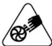
MATEPNAH! O6bpeTe BHMaHne Ha eBeHTyaJIHn N3JItAHNHa MaTePnaI, PpeIN3BnKaHn OT Bb3dUShn INOTOK, KOHTO MoTa Da npuHrT TeKn HapaHraHHa Ha Xopa INI ppeMeTu.
ONACHOCT OT N3JNTAUN
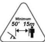
MATEPHAJIH!IbpeMeHa n3noJ3BaHe Ha MaunHaTa OTdaJeTe Ha NOHe 15 M. BCNUKXopa NnDOMaHN JKNBOTHN!
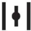
OnachocOT OTp83BaHe Ha KpaHnK!DpbXTe BnHaRn PbceTe daleyOTpeWetKaTa, KOrTO Ce HAMnpa Ha BXoD Bb3dYx. BbpTAAOTO ce pa60THo KOJIeIo (poTopa) MoKe Da npuHHn cepno3Hn HapaHraHn.
OnachocOT cepno3Hn HapaHbBaHnI! DpbKTe daJeC ot peWeTKaTa pa6oTHO oBleKnO C pa3BbBaUc Ce YactN, 3auTo6nxMaMOrn Da ce 3anLeTaT B pa6oTHOTO KOJIeNo (poTopa) n da npuHnT TeKHi HapaHbAHH.
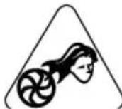
OnachocOT Cepno3Hn HapaHbAHn! DpbKTe daJeu OT peWetkata, KOrTO ce Hamnpa Ha BXoD Bb3dyX, BaWaTa Koca, 3aIoTO 6n MoRna Da ce 3aIneTe B pa60THOTO KoJeLo (poTopa) N Da npUHH TeKKn HapaHbAHnA. Ako Imate DblrN KocN, BbpKeTe rNo NOxOJHnHaun.
BAHHO NOBpeHnTe Hn HeeTnBnTe CTnKePN Tp6Ba Da Ce 3aMeHrT C HOb. HobTe CTnKePN MoTa 6bDaT 3aBeHn B OToPn3npaH CepBn3eH ueHTbp.
3.3 INEHTNΦHKAUHOHEETHKET HA NPOyRTA
Ha ndentnФнkaunOHnnaETca nocouehn cIeHnTe daHHN (fHr.1).
- HINBO Ha 3ByKOba MOUHOCT
- Маркниpoька за сбOTВETCTBNE CE
3.ФОДИHAHaПОПЗВODICTBO - BvД MaunHa
- CepneH Homep
6.Иme n aDpec Ha npOn3BOuNTeIa - HoJHa apTnKyJ
IpeHnWeTe HdeHTnФKaUHOHHte DaHHHa MaunHaTa Ha CbOTBETHte MeCTaHa eTKeTa, KOTo CE HAmnpa OT3aHa KOpuata Ha pBkoBOdTBOTO.
BAHHO 3nnon3BaTe
IeHTnKauHnTe DaHHN, KOnTO Ca IocOeyHn Ha IeHTnKauNoHHn EtnKeT Ha npOyKa TBeH NbT, KOrATo Ce CBp3BaTe COTOpuHa pa6oTnHnua.
3.4 OCHOBHN KOMNOHEHTN
MaunhaTa ce cBcToi OT CKeHnTe OCHOBN KOMNoHEHTN,Ha KOnTO OTROBaPc CKeHnATo fYHKUHOHaHnOCT (ΦnR.1):
A.Дигател:празда вдьнжени на paботноTO колю (poTopa).
B. 06dyxbaa Tpb6a: npedpa3noJKeHa 3a n3TlaackBaHe Ha Bb3dyuH NOTOK.
C.PbKoXBaTHa 3a ynpabIeHHe:IO3BOJIBa 3aJeNCTBaHe Ha KOMaHdITe Ha MaShHaTa Hn HacoUBaHe Ha O6dyXBaUaTa Tpb6a.
D. Pe3epBoap 3a rOpHbO: ToBa e pe3epBoapa 3a rOpHbO, KOeTo 3axpaHbA DnRaTeJIa.
E. Onopha nloya: TOBa e nloyata, Bbpyx KoITo e N03nOHHpaHa MaunHaTa. Cha6deHa e c pbKoXBaTHa 3a yleChraBaHe Ha TpaHcnpTnpaHETo Hn He Ca CBbp3An npncnOc6JIeHNrTa 3a 3aKaUBaHe Ha MaunHaTa NoCTabeHa Ha pamOTO. Cha6deHa e c cnCTema 3a amOptn3npaHe Ha Bn6paUNTe, KOITo OTCTpAHRA RoJMa qACT OT TgX IO BpeMe Ha fynKuOHpHaHTo.
F.Ппсncoc6леняза поставные
На Maшнота Ha paMo:В случая
са n3pa60TeHи OT спeцална Тьkan
<|im_start|>assistant
I npemHHaBt Ha pamHeTe I NOMaraT 3a NOdIbPkaHe Ha terIoTO Ha MaunHata No BpeMe Ha pa6ota.
G.ДИнhamOMeTpneHraeueHKnIOU: INHCTpyMeHT,KOHTOceN3PON3Ba3a 3aBbPtaHeHaBnHTObe,raIKN60JTOBe, 3aJa ce 3aTeHnatIINpa3Xna6rT.
4. MOHTHPAHE
BAHHO HopMnte 3a 6e30nachoCT, KOHTo Tp86Ba Da ce Cna3BaT, ca ONcaHN B rI.2.Cna3BaTe cTpKTHO Te3u Ka3aHn, C ue InpedOTbpaTbaHe Ha cepno3HN pNcKObe Hn ONaCHOCTn.
3apaHn cHlaIpaHHeTo n TpaHCnOpTa, HAKO KOMNoHENTn Ha MaunHaTa He ca Crlo6eHN BbB φa6pHKaTa, a Tpa6Ba Da 6bDat MOHTnpAHn CLeD OTCTpaHReBaHe Ha OnaKOBKaTa, KaTO ce CLeDbat CLeDHnTe INHCTpyKcN.
Pa3oHaHOBaHoTo n 3aBbPbWAHeTo Ha MOHTaHa TpA6Ba Da Ce N3BbPwN BbPxy paBHa N 3dpAba NOBbPxHocT, C DOCTaTbUHO IpOcTpaHCTBO 3a DnHeHne Ha MaunHaTa N IpemecTbaHe Ha ONaHOBHNe, Hato N3NoJ3BaTe BnHaHn NODXoJauN HHcTpymEn. Da He ce N3NoJ3Ba MaunHaTa, Ppei Da Cte 3aBbPwJIn OepaunHe No MOHTnpaHeto, Yka3aHN B pa3dEe "MOHTAH".
4.1 KOMNHOENTN 3A MOHTNPAHE
B onaKOBkata ca BKLIOUeHIN KOMNOHEHTIte 3a MOHTaK.
4.1.1 Pa3onaKaObaHe
- OTbOpTe ONaKOBkAta BHIMaTeJHo, KaTO BHIMaBaTe Da He 3aRy6nte KOMNoHEHTnTe.
- BnKTe 3a cnpaBka DOKyMeHtauNraTa, KOrTo e NOCTaBeHa B KyTna, BKIOUHTeJIHO HAcTOAUNTE HNCTpyKcNn.
3.ИЗвадеTe OT KUТЯТа BCYNКИ HEMOHТиРаНКOMПОЕHTN.
4.ИЗва对接 МашиннаТОКУТЯ.TA - YHnOxHeTe KyTHaTn ONaKOBHnTE B CbOTBeTCTBnE C MeCTHnTE pa3Nope6n.
4.1.2 MoNTaH Ha o6dyXbaaTa Tpb6a HnHa pBHOXBaTHKaTa 3a ynpabLeHne
-
BhapaTe rBbKaTa Tp6a (Φn.r. 3.B) B Tp6aTa 3a n3JIH3aHe Ha Bb3dYx (Φn.r. 3.A) n ΦHKcnpaTe cKo6aTa c OTBePka, 3a Da r 3aKaUHTe CTa6nHIO.
-
BhapaTe Tpb6aTa (ΦnR.3.C) B TbBkAbaTa Tpb6a (ΦnR.3.B) KaTo BHIMaBaTe N3PbKHalaTa YacT (ΦnR.3.G) Da e OsbpHaTa HaOly. ΦHKcnpaTe cKo6aTa C OTBepKa, 3a Da 3aKaChTe cTa6uHNo Tpb6nte.
- BhapaTe onopata Ha pbKoXbaTkata 3a ynpablenne (ФИг. 3.H)ВТрбаTe (ФИг. 3.C), KaToЯ NOdpabHnTe c n3ПьКналata YacT (ФИг. 3.G). ПоЗинонpaJIte yxOTo (прсTeHa) (ФИг. 3.I)Визпьнhalata YacT (ФИг. 3.J).
4.ФИКСИРаTe pькoxBaTHkaTа 3aуnpaВлeнe (ФИr.3.K)иЗавиTe BnHTa (ФИr.3.L). - Ппекаши Кабела в Два Табелонрова (Фиг. 3.M).
6.Подрав overheTe OTdelenHneTo Ha Tpb6aTa (ФИг.3.D)c n3nBkHaJata qacT (ФИг. 3.N)Ha Tpb6aTa (ФИг.3.C).N36yTaIte Tpb6aTa (ФИг.3.C)nЯЗврTeHa 90^ no nocokaHa yacOBHKOBaTa cTpeIka,3aJa r3aKaUHTe CTa6HJIHO. - CLeBaIte npoceDypaTa, KOrTo e OINcHa B IpeXoHnTe DBe TocKn, 3a Da MOHTnpaTe Tpb6aT (ΦIr. 3.E) n KpaHnTa Yact Ha o6dyXbaUaT a Tpb6a (ΦIr. 3.F).
4.1.3 DemoHTaHa 06dyXbaaTa Ta Tpb6a
BAHHO CnpTe MaunHaTa (nap. 6.5) BceHn nT, KOrato ce cBaJra obdyXbaaTa Tpb6a.
B 3aBnCmOCT OT BnDa Ha TpBb6aTa:
-AKo Tpb6ataeΦnKcnpaHa c 3axBa7a7a ce n3nBkHala qact,3aBbpteteЯ NO NocKa 06paTHa Ha yacOBHNKObaTa CTpeIHa.
-AKo Tpb6aTa e fHKnpaHa CbC ChO6n, pa3BnTe cHObnte C nOMoUta Ha OTBepHa N DEMOHtnpaIte Tpb6nte.
5. KOMAHДN 3A YYPABJIENHE
5.1 JIOCT 3A YNPABJIeHNE HA YCHOPHTEJIa
Locta 3a ynpablenHe Ha ychopnteHa (Hr. 4.A) no3boJbA da ce perylnpa ckopocTtHa BbptHe Ha pa60HTo KOJIeO (poToPA).
CkopocTtHa BbPteHe Ha pa6OTHO KOJIeNo (poTopa) Tp8Ba Da OTROBapr Ha BnDa Ha n3BbPwBaHaTa pa6Ota (rI. 6.4.1) n MoKe da ce peYunpa KaTO Ce OKaKe NO-CNlHO HnIO NoLeKO HaTHsCKaHe Ha KOMaHdaTa Ha yCKOpHTeJMaKcImaHata CkOpcT Ha pa6Ota ce NOCTHra C KOMaHdaTa Ha yCKOpHTeJnPnBeDeHa B KpaR Ha XoJa.
5.2 JIOCT 3A PEGYJINPAHE HA YCHOPHTEJI N CINPAHE HA DBNIGATEJI
JocTa (ΦnR. 4.B) n3nBnHЯBa DBOH OdEiCTBHe:
- N03BOLIbA 3aDeiCTBaHe n cnHpaHe Ha dBnraTeJIa.

Дигагелт ce cnupa (Фиг. 4.C).
Ako locta e no3nioHnpaB Dpyrno nocOn, DBnraTeJIaT MoKe Da ce 3aDenCTBa n npnbde B CbCToHHe Ha yHKuOHNpaHe.
2.ПОЗВОЛЯВада ceperулра chopocTTa Ha BbpteteHa pa6OTHOTo KOJIeLo (poTopa),noIbpaKaHn ychOpHTeJrT 6IOKHPaH B JKeJaHOTo NIOJOKeHHe. ChopocTtHaBbpteneHa pa6OTHOTo KOJIeLo (poTopa)MoHe da ce perylnpa KaTO Ce 3aBbPTn loCTa HADyIn nII Harope.MaKcImaJIHa cHOPoCT ce noCTnra C loCT 3aBbptAH3qILO HaIoNl.
3A6EJIeHHA IpenopbYBa ce,da ce H3NoJ3Ba FyHKuYra 3a peRyIIPAhe Ha yChOpHTeI NO BpeMe Ha Dblr pa6OTn, 3a Da Ce N36BerHe Da Ce DbpKHe HEnpeKbCHAto HAtNCHaT LoCTa 3a ynpabLeHne Ha yChOpHTeI.
5.3 KOMAHDA HA DPOCEJIHATA HJIANA (CHOKE)
I3noJ3Ba ce 3a 3aJeicTbaHe npn cTydeHDbiratel. KomahdaTa Ha dpocenHaTa Klaana (choke) mMa Tprn POnuN:

7.2 IPIHOTBARE HA TOPHBHATA CMEC
Ta3n MaunHa e Cha6deHa C DByTaKTOB MOTOP, KOIto H3NCKBa 3a TOpNBO CMEC OT 6eH3nH n Cma3OuHO MacNo.
BAHHO YIOTpe6aTa eINHCTBeHO Ha 6eHN BODI DO NOBpeHa MoTOpa N OTMeHn IpaBOTO 3a NoJ3BaHe Ha rapaHcN.
BAHHO 3nno3BaIte eDnHCTBeHO KaueCTBeHr TOpNBa H Macla 3a DObpTo FyHKuOHnpAHe Ha MaunHaTa n rapaHTnpAHe IpoDbJIHnTEJIHoCTTa Ha KINBOT Ha MExaHnHnTe Yaactn.
7.2.1 XapaHTepnCTnHa Ha 6eH3nHa
H3noJI3BaIte eINHCTBeHO 6e3OIOBEN 6eH3nH (3eJIeHO O3HaueHne) CbC CTOnHOCT Ha OKTaHa He No-Hncha OT 90 N.O.
BAHHO 3eHnT 6EH3nH BODn DO
0bpa3yBaHe Ha yTaHn B pe3epBoapa,
aHO Ce cBxpanHa NOBue O T Dba Meceua.
BnHarn n3non3BaIte He3actoJl 6EH3nH!
7.2.2 XapaKTepeHCTnHaMaCJIoTO
H3noJ3BaIte eINHCTBEHO CNHTeTNUHO
MACNo C OTInuHo KaueCTBO, PpeHa3NaueHo
3a DByTaKTOBn DBnraTeJI, C TexHnueckn
DaHHn CbIacHo JASO FC.
Ppi Baunr npodabau-HoHCyIaHT ca HaJIuHn
Macna, CneuaJIHo pa3pa60TeHN 3a To3n BVd
MOTOpN, KOITOr rapaHTnpaT BnCOKa 3aUNTa.
Ynotpe6aTa Ha Te3n Macna PO3BOJIraBa
CbCTABReHTo Ha 2,5%-OBA CMEc,
PpeDCTaBnRABa7eHa Yact MACIo
Ha BCEKn 40 qactn 6eH3nH.
7.3 3APEHDAHE C TOPNBO
3apeHdaHeTo c rOpuBO Tpa6Ba da ce H3BbPwBa npn CnpaHa MaunHa N OTKaueHa KaNaUHa.
Ipei Da npncTbNITe KbM 3apeKdaHe:
- Pa3KlataTe Do6pe Cmecta B Ty6ata.
- NocTaBete MaunHaTb Cta6nHa No3nHa Ha paBHO, KaTo npo6KaTa Ha pe3epBoapa Ha CmecTa e HacOeHa Harope.
3A6EJEXHA Ha npo6kata Ha pe3epboapa Ha MacNoTo (Hr. 11.A) e NOCTaBeH CJIeHNr CNMBOI:

+Pe3epBoap 3a roPnBHa Cmec
3.ПоунстeteКаначkaТиЗОнATA OKOLO He,3aДa He ПОпадНВ pezeрвога оТпдьЧИnpOДУкTN IOBpeMe Ha 3apeKДaHETO.
4. Pa3BbPtaTe BHNMaTeJHo KaNaUKaTa Hape3epBoapa, 3a Da ce OTdEIn NOCTeNeHCO3daIOTO Ce BbTpe HauRaHe.
5. Пи зараздане Изпольвaite Фун,在КATO ГладаTe ДЯ He npelbHnTe pe3epBoapa Do p6a Ha OTBopa.
7.4 IOUHCTBAHE HA MALINHATA N HA DBNRATEJIAR
3a da ce HamaHn pNcKa OT noXap, NOUHCTBaIte MaunHaTa N Oco6eHO DBNraTeJI,OT OCTaTbCNIOT JnCTa N KIOHN.
-Поунстваite Винаг МашинаТа След
Нзползвае КATO ИЗПОЛЗВАТЕ УСТА Кьрпа,
НавлижHeHa B HeyTpaineДeTePreH.
- OTeTpaHbAte BCaKaBcIeDa OT Bnara, KaTo cn NocJyHnTe C MeHa n CyXa Kbpna. Blarata MoHe da npedn3BnKa pncHOe OT eJeKtpnueckn ydapn.
He n3noJ3BaIte arpeCnBn DeTepeReHTn nn pa3TBOpNTeIN 3a NOuNCTBaHc HnlaCTMaCOBInTe Yactn nn pkoXbaTKInTe.
He n3noJI3BaIte cTpyn BOda n 136aR BaIte da MOKpnte DBNrAteJn eJeKTPnuecknTe YaCTn.
- PoiDbpKaHTe BnHaHn pa6oTHOTO KOJIeNo (poTopa) YNCTO n 6e3 npax n OCTaTBu, O6DyXBaN CbC CfBCTEH Bb3dYx ppe3 peWetkata. He npbckaHTe pa6oTHOTo KOJIeNo (poTopa) c BOJa.
3a da ce n36erHn perepraBaHe n NOBpeKdaHe Ha DnrgateJ, npOBepraBae BnHaN daJIi acnpaunOHnTe peWetKn Ha OxJaKaaIbB3dyxC aYnCTn N 6e OTpaDbu.
7.5 ΦИССРАЦИ ГAIКИ NBINTOBE
- PoiDbpKaHaTe 3aTeHaNraHnTe H BnHTOBeTe, 3a Da CTe CNrpyHn, Ye MaunHaTa Ce HAMnpa BnHarN B CbCTOarHne Da FyHKUOHnpa 6e3oNaCHO.
- PpOBePRAIte peIOBHO daII npkoXbATKHTe ca 3aHpeNeHn 3dpBO.
8.2 NPOBEPHA HA CBEUHTA
CBeuTa (Φnrg. 9.G) eDocTbHa KaTo ce CBAH KanayKaTa (Φnrg. 9.F).
CBeuTa Tp86Ba Da 6bDe 3aMeHeHa C Dpyra, c aHaIOrnHn XapaKTepeNtKn, B Cnyau, ye eJeKToPeTc Ca n3ropeIn Nn N3OJaunrTa e n3HoCeHa, n TaKa nn HNaue - Ha BceHn 100 pa6oTHn Yaca.
3a n3BbPwBaHe Ha onepaunn NO CBeuTa ce 06bpHeTe KbM dNCTpN6yTopa NIN OTOpN3npaH cepBn3eH cHTbp. Lc Ce OTHacr DO HameCnTe NO CBeuTa, BnTe 3a CnpabHa TaBncaTa C onepaunTe no NopdpbJHKata n TaBncaTa 3a OTKpNbAHe Ha Hen3npaBHOCTn.
8.3 CTAPTOB LHYP
CTapTOBnI shHyp TpR6Ba Da ce 3aMeHN OT BaShIN IpoDabAch-KOHcyIHT, pN IONBA Ha IIpbBNTe CLEdN OT N3HOCBaHe.
8.4 HACTPOINHA HA KAPBYPATOPA
Kap6bypaTopbTe e fo6pnHo HAcTpoEH TaHa, Ye Da NoCTnIgHe MaKcImaJIHa eFeKTINBHOCT npn BcRAKe aEDHa yNoTpe6a, C MInHMaJIHO OTdEJIHe Ha BpeHN emNCn, CLeDBAIKN DeIcTBaUHTe HopMaTINBn.
BcnyaHa lowa pa6oTa,obbpeTe ce KbMa BaaNpaOdaBaay-KOHcyJTAHT 3a npOBepKa Ha Kap6bypaTopa N MOTopa.
HacTroika Ha Kap6bypaTopa:
T=HaCtpoHkaHaMHNMyM
L = HactpoRnKa ropBHa cMec 3a HnCKa cKopoCt
H=HaCtpoRnKa rOpNBa Cmec
3a BINGOKA CHOPOCT
9. ПИБИРАЕ 3A СьХРАЕнUE
BAHHO IpaBnIata 3a 6e3oNaCHOCT, KOHTo TpRbBa Da ce Cna3BaT NO BpeMe Ha OnpaunTe 3a np6bpaHe 3a CbXpaHbAHe, Ca OnncAHn B nap.2.4.Cna3BaHTe CTPNTHO Te3n yka3aHn, CueI npEDoTbpaTaBaHe Ha cepNo3Hn pNcKOBe Hn ONaCHOCTH.
9.1 ПИБИРАН HA MAUIHATA 3A CbXPAHEHNE
Korato MaunHaTa Hma Da ce n3noI3Ba 3a nepnoD no-DbIbT O T 2-3 Mececa, ce HaIar a Da B3eMeTe HKOIN MepKn, 3a Da n36BerHete TpydHOCTn Pn CneBa7a pa60Ta C MaunHaTa nn CbotBETn TpaHn Uetn Bbpx Myotopa.
Ppei da npnbepeMaunHaTa:
1.ИзпраэнеpeзервараHa ropиВоTo HaOTkpntOипсntCTydeHDbnraTeI.
2. HarlaCeTe DnIraTeJIaT Ha MNHmym N OCTaBeTe MaunHaTa Da pa6oTu Do H3pa3XoDbAHe Ha BCNUKOTO rOpNBO, KOeTo e octaHaIo B Kap6ypaTopa.
3.OCTaBete DnRaTeJda ce OxlaI.
4. NocTeTe cTapaTeHnMoMaHHaTa.
5. Побере Te Далу Няма pa3xla6eHIn
Илп NOврededи KOMПОЕНТ. Ак e
Heo6xOДМо, CmHeTe NOВpeDEHNTe
KOMПОЕНТи 3aTeHHTe eBEHTyaJIHn
pa3xla6eHn BINTOBe И bOLTObe Илсce
CBbPKeTe C OTOpN3IpaH cepBn3eH ueHTbP.
6. Pn6epeMaHHaTa 3a CbXpaHeHne:
B CYXO NOMEUHNE
-3aunTeHaOT He6laonprrTHn aTMOCepHNrBHeHn
- Ha MRCTO HeoCTbNHO 3a Deua,
-KaTO CE yBepnTe,Ye CTE CBaJIINN KIOUbT NIN INHCTpyMeHTnTe
H3noJ3BaHn 3a noDpBkKaTa.
B MOMeHTa Ha npBBeKdaHe Ha MaUNHaTa B DeiCTBne:
- NpOraTBeMaunHaTa (rJ.6).
10. ПЕМECTBAHE ИТРАHCIOPTИРАСЕ
Bcekn nT, KOraTo Tp6Ba Da npemecTBaTe nn TpaHcnpOpTpapeMaunHaTa,e Heo6xoJMo:
- Cnpete MaunHaTa (nap. 6.5).
-ИЗчakайтспранетоHa poTopa.
-OTkauheTe kanaaKaTa oT CBeuTa (ΦnR.9.G).
-XBaUaIeMaunHaTa eINHCTBeHO 3a DpbKHe HacoYBaTe Tpb6nTe, TaKa Ye Da He Cb3daBaTe npenrTcBne.
Korato ce TpaHcnpTnpa MaunHaTa C TpaHCnoptHO cpeCTBO e Heo6xOIMo:
-Да CBaJIInTe Tpb6nTe;
- npTpaHcnpTnpaHe 06e3onacete No NOxOJaH NaHn KaTo n3NoJ3BaTe BbKeTa nnBepn;
- MaunHaTa Da ce No3nOHHpa TaKa, Ye Da He NpeIcTabJIbBa ONaCHOCT 3a HNKOrO.
11. TEXHnueCHO OBCJyKBAHE N IONPABKN
ToBa pBKOBOCTBO npEoCTaB BcNKn yTbAHnHa, Heo6XODIMn 3a ynpabJIeHneTO Ha MaunHaTa n 3a n3BbPWBaHe Ha npabINHa OCHOBn IOdpbHKa OT Notpe6nteJ. BcNKn OepaHn no peryIlnpaHTo n NOdRpKKaTa, KOHTo He ca ONncAHn B TOBa pBKOBOCTBO, Tp6Ba Da 6bDaT n3BbPWBaHn npn BaHn DnCTpNoTyOp nIn B cneuaJIIN3HpaH ceHTbp 3a o6CnyKBaHe, KOHTo pa3noJa r C Heo6XODIMnTe No3HaHn I INCTpyMeHTn 3a npaBnIHOTo n3BbPWBaHe Ha pa6OtaT a, KaTO Ce 3aapani CTeneHTa Ha 6e3onacHOCT n PbBOHaJALHO TcBCTOJHHe Ha MaunHaT a. OepaHn, n3BbPWeHn OT HeKOMnTeHTHn NlUa nII PhmN BOJr DO OTndaHne Ha BCRAKABA rapaHcHn I BCRAKABO 3aJbLnKeHne HIn OTROBOPHOCT Ha POnI3BOIDNTeJ.
- Camo Otopn3npaHn pa60THHn3a texHHuecko 06cnyKbaHe MOrat da n3BbPWBat NoppaBn I NOdApbKa, KOrato MaunHaTa e B rapaHn.
- Otopn3npaHnTe pa60TnHnCnTe 3a texnuecko 06cnykBaHe n3noJ3BaTe eHNCTBeHO opnHaJIHn pe3epBn qactn. OpnHaJIHnTe pe3epBn qactn n npHaJeHHoCTn ca cneuaJIHo pa3pa6OteHn 3a MaunHnTe.
OpunHaHnTe pe3epBn qactn npHaJeKHOCTn ca cneuaHOP pa3pa6oTeHN 3a MaunHnTe.
He ce oO6pBa n3noJ3BaHeto Ha HeopnHaJIHn pe3epBHN qactN n npHaIeJHKoCTn; n3noJ3BaHeto Ha HeopnHaJIHn pe3epBHN qactN
I npHaJdJeKHOCTN KOMnpOMeTnpa 6e3oNaChOcTTa Ha MaunHaTa N OCBo6oKaDaBa Ipon3BODHTeJIrOT BCaKBO 3aDbJKeHHe N OTROBOPHOCT.
- PpenopbUba ce da 3aKapate MaunHaTa BeHbB rOdnHaTBA OToPn3npaHa pa6oTnHnua 3a Texnuecho 06cnyBaHe, 3a n3BbPwBaHe Ha noDpBkka, Texnuecho 06cnyBaHe n npOBepKa Ha npedna3HnTe yCTpoiCTBa.
12. TAPAHUOHHO NOKPITNE
IapaanraTnOKpnaBvBCnKnDeΦeKTHn Ha MaTePnAJI, KaKTo I npOn3BOdCTBeHn DeΦeKTH. NopTeBnTeJrTpr6Ba Da CLeDBA BHIMaTeJIHO BCnKn PpeOCTaBeHn HNCTpyKuBn B pInNoKeHaTa DOkUMeHTaun. IpaanraTa He nokpnBa Bpei/ 1eTn DblKaun Ce Ha:
- Heno3HaBaHe Ha npDpyKabaaTa aDOKyMeHTaun.
HeBHaHne. - HenpaBnHIO n3NoJ3BaHe mOHTaK nn HecBOICTBeHO n3NoJ3BaHe.
-ИзнолзВане Ha HeopинHaJIHn pe3epBHy qaCTn. - I3noJ3BaHe Ha npHnAdJeKHoCTN, KOHTO He ca DoCTaBeHN nn TaKNBa, KOHTO He ca Odo6peHH OT npOn3BOIDnteJI.
Ocben ToBa, rapaHcIyTa He noKpInBa:
- HopmaHOTOn ɪzHOCBaHe Ha KoHCymaTbNTe.
- HopmaHTo n3HOCBaHe.
Notpe6nteIe 3aunTeH OT DeNCTBaUTo
HaunohalHO 3akOHoTaTeJCTBO. PpaBata Ha
notpe6nteI npedBnDHeN OT DeNCTBaUTo
HaunOHALHO 3akOHoTaTeJICTBO NO
HnKaKbB NaHH He Ce OpaHnUbaT
OT HAcTOAATA rapaHcNIA.
13. TABJIHICA HA ONEPAUHTE NO NODPbHKATA
6.4 PRACOVNI CINNOST
3.3 TYPESKILT PÅ PRODUKTET
These Maschine woke me up. "I'm sorry for it."
3.1 Description of the machine and planned use.. 4
3.2 Safety signs 5
3.3 Product identification label 5
3.4 Main components.. 5
- ASSEMBLY 6
4.1 Assembly components 6
5.CONTROLS. 6
5.1 Throttle control lever.. 6
5.2 Throttle adjuster and engine stop lever.. 6
5.3 Choke control 7
5.4 Primer control button 7
5.5 Handle for manual start 7
- USING THE MACHINE 7
6.1 Preparation 7
6.2 Safety checks 7
6.3 Start-up 8
6.4 Working 8
6.5 Stop 9
6.6 After use 9
- ROUTINE MAINTENANCE 9
7.1 General information 9
7.2 Preparing the fuel mixture 9
7.3 Refuelling 10
7.4 Cleaning the machine and the engine 10
7.5 Nuts and bolts 11
- OCCASIONAL MAINTENANCE 11
8.1 Cleaning the air filter.. 11
8.2 Checking the spark plug 11
8.3 Starter rope 11
8.4 Tuning the carburettor 11
- STORING 11
9.1 Storing 11
-
HANDLING AND TRANSPORTATION 12
-
ASSISTANCE AND REPAIRS 12
- WARRANTY COVERAGE 12
13.MAINTENANCE TABLE. 12
14.PROBLEM IDENTIFICATION. 13
1. GENERAL INFORMATION
1.1 HOW TO READ THE MANUAL
Some paragraphs in the manual contain important information regarding safety and operation and are emphasized in this manner:
NOTE or IMPORTANT These give details or further information on what has been previously indicated and aim to prevent damage to the machine or cause other damage.
The symbol highlights danger. Failure to observe the warning can lead to the risk of injury to oneself and others and/or damage.
The paragraphs highlighted in a square with grey spots indicate the optional characteristics not on all models documented in this manual. Check if the characteristic is on this model.
Whenever reference is made to a position on the machine "front", "back", "left" or "right" hand side, this refers to the operator's working position.
1.2 REFERENCES
1.2.1 Figures
The figures in these instructions for use are numbered 1, 2, 3, etc.
Components shown in the figures are marked A, B, C, etc.
Reference to component C in figure 2 is indicated with the wording: "See fig. 2.C" or simply "(Fig. 2.C)".
The figures are given as a guide only. The actual pieces can differ from those illustrated in this document.
1.2.2 Titles
The manual is divided into chapters and paragraphs. The title of paragraph "2.1 Training" is a sub-title of "2. Safety regulations". References to titles or paragraphs are marked with the abbreviation chap. or par. and the relevant number. Example: "chap. 2" or "par. 2.1.
2. SAFETY REGULATIONS
2.1 TRAINING
Become familiar with the controls and the proper use of the machine. Learn how to stop the machine quickly. Failure to follow the warnings and instructions may result in fire and/or serious injury.
- Never allow children or persons unfamiliar with these instructions to use the machine. Local regulations may restrict the age of the operator.
- Never use the machine if the user is tired or unwell, or has taken medicine, drugs, alcohol or any substances which may slow his reflexes and compromise his judgement.
- Bear in mind that the operator or user is responsible for accidents or unexpected events occurring to other people or their property. It is the user's responsibility to assess the potential risk of the area where work is to be carried out and to take all the necessary precautions to ensure his own safety and that of others, particularly on slopes or rough, slippery and unstable ground.
- If the machine is sold or lent to others, make sure that the operator looks over the user instructions contained in this manual.
2.2 PREPARATION
Personal Protective Equipment (PPE)
- Wear suitable clothing, strong work shoes with anti-slip soles, and long pants. Do not operate the machine barefoot or wearing open sandals. Wear ear-protection devices, anti-vibration gloves, protective goggles, and a half mask respirator.
- This machine is extremely noisy and operators must wear acoustic protection equipment.
- Use of hearing protections can reduce the ability to hear any warnings (shouting or alarms). Be careful of what occurs around you in the work area.
- Never wear scarves, shirts, necklaces, bracelets, loose flowing clothing, laces or ties or any hanging or flapping accessory that could catch in the machine or in any objects or materials in the work area.
- Tie your hair back if it is long.
Work area / Machine
- Thoroughly inspect the whole work area and use a rake or yard brush to manually untangle debris, remove anything that could be projected by the machine (when used as a blower), block the vacuum tube (when the machine is used
as vacuum collector), or be a source of hazard (stones, branches, steel wire, bones etc.)
- When operating in dry dusty soil conditions, it is recommended to moisten the surface slightly.
Internal combustion engines: fuel
DANGER! Petrol and the fuel mixture are highly flammable!
DANGER! Fuel is highly flammable. Keep the petrol and fuel mixture in approved fuel containers, in a safe place, away from any naked lights or heat sources.
- Keep the fuel containers and storage area free of grass cuttings, leaves, or excessive grease.
- Keep the containers out of the reach of children.
- Do not smoke when preparing the mixture, when filling or topping up with fuel or when handling the fuel.
- Use a funnel to top up with fuel only in the open air.
- Do not inhale fuel fumes.
- Never remove the tank cap or add fuel while the engine is running or when the engine is hot.
- Open the fuel tank slowly to allow the pressure inside to decrease gradually.
- Do not approach the tank opening with a naked flame to check its contents.
- If you have spilled some fuel, do not attempt to start the engine but move the machine away from the area of spillage and avoid creating any source of ignition until the fuel has evaporated and fuel vapours have dissipated.
- Immediately clean up all traces of fuel spilt on the machine or on the ground.
- Replace caps of all fuel tanks and containers securely.
- Never start the machine in the same place in which you refilled it with fuel; the engine must be started in an area at least 3 metres from where you refuelled.
- If fuel is spilt on clothing, change clothing before starting the engine.
2.3 DURING OPERATION
Work area
- Do not operate the engine in a confined space where dangerous carbon monoxide fumes can develop. All starting operations have to be effected in an open or well ventilated area. Always remember that exhaust fumes are toxic.
- When starting up the machine, do not direct the silencer and therefore the exhaust fumes towards flammable materials.
- Do not use the machine in environments at risk of explosion, in the presence of flammable liquids, gas or powder. Electrical contacts
and mechanical friction can generate sparks that can ignite the powder or vapours.
- Never use the machine in confined spaces, in the presence of fumes, in an explosive environment or close to inflammable materials or electrical equipment.
- Work only in daylight or with good artificial light in good visibility conditions.
- Keep persons, children and animals away from the working area. Get another adult to keep the children under supervision.
- Check that there is nobody within at least 15 metres of the machine's range of action.
- Where possible, avoid working on wet, slippery ground or in any case on uneven or steep ground that does not guarantee stability for the operator.
- Avoid working with wet grass, in the rain and when there is a risk of a thunderstorm, especially lightening.
- Pay careful attention to uneven ground (hills, dips), slopes, hidden hazards and obstacles that could limit visibility.
- Be very careful near ravines, ditches or embankments.
- Always assess wind direction and never work against the wind.
- Do not use of the machine near open windows.
- During use, prevent removed material from accumulating in the outfeed area that could be projected into the vacuum inlets.
- Look out for traffic when using the machine near the road.
- To avoid the risk of fire, do not leave the machine with the engine hot on leaves, dry grass or other flammable material.
Behaviour
- When performing work utilising the machine as blower, the machine must always be held firmly with the right hand on the upper handgrip.
- When performing work using the machine as vacuum collector (of provided), it must always be held firmly with both hands, with the right hand on the upper handgrip and the left hand on the lower handgrip, so that the collection bag is on the operator's left.
Always use caution and take on a firm and well-balanced position. - Do not lose your balance.
- Make sure to avoid violent impacts against foreign bodies and prevent the air flow from throwing any material and dust.
- Do not direct the air jet towards persons or animals
-
When used as a blower always pay the utmost attention to prevent removed material or dust from injuring people or animals or damaging property.
-
When using the vacuum (if applicable) do not manually insert objects in the vacuum inlet and avoid the intake of large objects that could damage the rotor.
- Never run, always walk.
- Keep your face, hands and body away from the vacuum vent (when using as a vacuum, if applicable) and from the air exhaust (when using as blower).
- Do not obstruct air passageways both during start-up and during machine use.
- The rotating parts can cause serious injuries; avoid contact with these parts while they are still rotating.
-
Do not touch the engine parts which heat up during use. Burns hazard.
-
If something breaks or an accident occurs during work, turn off the engine immediately and move the machine away to prevent further damage; if an accident occurs with injuries or third parties are injured, carry out the first aid measures most suitable for the situation immediately and contact the medical authorities for any necessary health care. Carefully remove any debris which could cause damage or injury to persons or animals if ignored.
- Prolonged exposure to vibrations can cause injuries and neurovascular disorders (also called "Raynaud's syndrome" or "white finger"), especially to people suffering from circulation disorders. The symptoms can regard the hands, wrists and fingers and are shown through loss of sensitivity, torpor, itching, pain and discolouring of or structural changes to the skin. These effects can be worsened by low ambient temperatures and/or by gripping the hand grips excessively tightly. If the symptoms occur, the length of time the machine is used must be reduced and a doctor consulted.
Use limitations
- When performing work utilising the machine as blower, the machine must always be held firmly with the right hand on the upper handgrip.
- Do not use the machine if you are unable to hold it with both hands or keep it steady on your legs while working.
- Never use the machine with damaged, missing or incorrectly positioned guards.
- Never use the machine without having installed all the attachments required for each use (as blower or vacuum collector).
- Never disengage, deactivate, remove or tamper with the safety systems/ micro switches installed.
- Do not alter the engine adjustments, nor over-run it. If the engine is forced to work
with an excessive number of rotations, the risk of personal injury increases.
- Do not strain the machine too much and do not use a small machine for heavy-duty work. If you use the right machine, you will reduce the risk of hazards and improve the quality of your work.
Ensure regular maintenance and correct storage to maintain machine safety and high performance levels.
Maintenance
- Never use the machine with worn or damaged parts. Faulty or worn-out parts must always be replaced and never repaired.
- To reduce the risk of fire, regularly check the machine for oil and/or fuel leaks.
The noise and vibration levels shown in these instructions are the maximum levels for use of the machine. Suitable preventive measures must be adopted to eliminate possible harm caused by high noise levels and vibration-induced stresses; utilise the machine at constant speed, firmly hold the handgrip with adequate strength, utilise the machine at the minimum speed required to perform the work, wear ear-protection devices, make frequent and adequate pauses during the work.
Storage
- Do not store the machine with fuel in the tank in an area where fuel vapours could reach a naked light, a spark or a strong heat source.
- To reduce fire risks, do not leave containers with debris inside a room.
2.5 ENVIRONMENTAL PROTECTION
Safeguarding the environment must be a relevant and priority aspect of machine use, of benefit to the community and the environment we live in.
- Avoid being a disturbance to the neighbourhood. Use this machine at reasonable times of the day only (not early morning or late evening when the noise could cause disturbance).
- Adhere strictly to the local regulations governing the disposal of packaging, oil, fuel, filters, damaged parts or any other element which may have an impact on the environment; this waste should not be disposed of along with standard household waste, but must be disposed of separately and sent to special waste disposal facilities for handling and recycling.
-
Scrupulously comply with local regulations for the disposal of waste materials
-
When the machine is withdrawn from service, do not dump it in the environment, but take it to a waste disposal facility in accordance with the local regulations in force.
3. GETTING TO KNOW THE MACHINE
3.1 DESCRIPTION OF THE MACHINE AND PLANNED USE
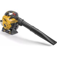
This machine is a garden tool, specifically a portable garden blower powered by an internal combustion engine.
The machine basically consists in a 2-stroke internal combustion engine that activates a rotor which is able to produce a high-speed air flow.
3.1.1 Intended use
This machine was designed and manufactured for:
the movement and accumulation, by blowing, of leaves, grass, debris of various limited weight and modest dimensions.
3.1.2 Improper use
Any other usage not in keeping with the above-mentioned ones may be hazardous and harm persons and/or damage things. Examples of improper use may include, but are not limited to:
- accumulation and collection of inflammable or explosive products, hot embers or combustion material without a flame, lit cigarettes, pieces of glass, sharp objects, metal objects, stones and any other object that could be dangerous to the operator and others;
aiming the air shot towards persons and/or animals; - allowing object to enter the suction grid;
- using the machine without the accessories specifically supplied by the manufacturer for specific uses, or use of accessories in a way not intended in these instructions;
- using of the machine by more than one person.
IMPORTANT Improper use of the machine will invalidate the warranty, relieve the Manufacturer from all liability, and the user will consequently be liable for all and any damage or injury to himself or others.
3.1.3 User types
This machine is intended for use by consumers, i.e. non-professional operators. It is intended for "DIY" use only.
3.2 SAFETY SIGNS
The machine has various symbols on it (fig. 2). They are used to remind the operator of the behaviour to follow to use it with the necessary attention and caution.
Meaning of symbols:

WARNING! DANGER! The failure to use this machine correctly can be hazardous for oneself and others.
WARNING! Read the instruction manual before using the machine.

Use ear protection devices and goggles.

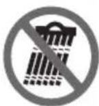
Do not leave the machine in the rain (or in damp conditions)
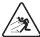
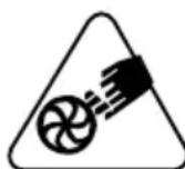
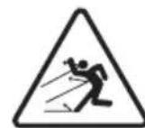
PROJECTION HAZARD! Pay attention to possible flying debris projected by the air flow: they can cause serious injuries to persons or damage to objects.
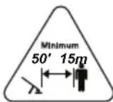
PROJECTION HAZARD! Keep any people or pets at least 15 m away when using the machine!
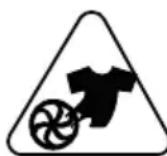
Mutilation hazard! Always keep the hands away from the air intake grille. The rotor in motion can cause serious injuries.
Serious injury hazard! Keep loose flowing clothing away from the air intake grille, as they could get tangled in the rotor and cause serious injuries.
Serious injury hazard! Keep hair away from the air intake grille, as it could get tangled in the rotor and cause serious injuries. Tie your hair back if it is long.
IMPORTANT Any damaged or illegible.
decals must be replaced. Order replacement
decals from an authorised assistance centre.
3.3 PRODUCT IDENTIFICATION LABEL
The product identification label provides the following data (fig. 1):
- Sound power level
- Conformity marking
- Year of manufacture
- Type of machine
- Serial number
- Name and address of Manufacturer
- Article code
Write the identification data of the machine in the specific space on the label on the back of the cover page.
IMPORTANT Quote the information on the product identification label whenever you contact an authorised service workshop.
IMPORTANT The example of the Declaration of Conformity is provided on the last pages of the manual.
3.4 MAIN COMPONENTS
The machine is composed of a series of main components that have the following functions (fig.1):
A. Engine: it drives the rotor.
B. Blower tube: it is the component through which the air flow is discharged.
C. Control handgrip: used to enable the machine commands and direct the blower tube.
D. Fuel tank: the container for the fuel used to power the engine.
E. Support plate: the plate on which the machine is positioned. It has a handgrip to make handling easier, and the harness straps are attached to the same when worn on the shoulder. It is equipped with a vibration damping system that eliminates most of the same during operations.
F. Harness straps: device made up of fabric belts which, placed over the
shoulders, help to support the weight of the machine during work.
G. Torque wrench: tool used to rotate screws, nuts and bolts, to tighten or loosen them.
4. ASSEMBLY
IMPORTANT The safety regulations to follow are described in chap. 2. Strictly comply with these indications to avoid serious risks or dangers.
For storage and transport purposes, some components of the machine are not installed in the factory and have to be assembled after unpacking. Follow the instructions below.
Unpacking and completing the assembly should be done on a flat and stable surface, with enough space for machine handling and its packaging, always making use of suitable equipment. Do not use the machine until all the indications provided in the "ASSEMBLY" section have been carried out.
4.1 ASSEMBLY COMPONENTS
The packaging includes assembly components.
4.1.1 Unpacking
- Carefully open the packaging, paying attention not to lose components.
- Consult the documentation in the box, including these instructions.
- Remove all the unassembled parts from the box.
- Remove the machine from the box.
- Dispose of the box and packaging in compliance with local regulations.
4.1.2 Assembling the blower tube and control handgrip
- Insert the flexible hose (Fig. 3.B) in the air discharge tube (Fig. 3.A) and use a screwdriver to tighten the clip and fasten the tube firmly in place.
- Insert the tube (Fig. 3.C) in the flexible hose (Fig. 3.B) making sure the overhang (Fig. 3.G) is facing down. Use a screwdriver to tighten the clip and fasten the tubes firmly in place.
- Insert the control handgrip support (Fig. 3.H) in the tube (Fig. 3.C) aligning it with the overhang (Fig. 3.G). Position the eyelet (Fig. 3.I) in the overhang (Fig. 3.J).
-
Fasten the control handgrip in place (Fig. 3.K) and tighten the screw (Fig. 3.L).
-
Thread the cable through the two cable ducts (Fig. 3.M).
- Align the tube housing (Fig. 3.D) with the overhang (Fig. 3.N) of the tube (Fig. 3.C). Push the tube (Fig. 3.C) and turn it 90 degrees clockwise to fasten it firmly in place.
- Follow the same process described in the two previous points to assemble the tube (Fig. 3.E) and the end of the blower tube (Fig. 3.F).
4.1.3 Removing blower tubes
IMPORTANT Stop the machine (par. 6.5) whenever the blowing tube is removed.
According to the tube type:
- If the tube is fastened with an interlocking overhang, turn it counter clockwise.
- If the tube is fastened with clips, use a screwdriver to unscrew the clips and remove the tubes.
5. CONTROLS
5.1 THROTTLE CONTROL LEVER
The throttle control lever (Fig. 4.A) makes it possible to control the speed of the rotor.
The rotor's speed must be adapted to the type of job being performed (chapter 6.4.1); it can be adjusted by applying more or less pressure on the throttle control. The maximum speed is reached by pressing the throttle control as far as possible.
5.2 THROTTLE ADJUSTER AND ENGINE STOP LEVER
The lever (Fig. 4.B) has a double function: 1. Used to start and stop the engine.

The engine stops (Fig. 4.C).
If the lever is positioned in other directions, the engine can be started.
- It allows adjusting of the rotor rotation speed, maintaining the throttle blocked in the desired position. The rotor rotation speed can be adjusted by turning the lever downwards or upwards. The maximum speed is reached by turning the lever downwards as far as possible.
NOTE We recommend using the throttle adjuster function during long work periods, to avoid having to keep pressing the throttle control lever.
5.3 CHOKE CONTROL
Used to turn on the engine when cold. The choke control has three positions:
Position A (Fig. 5.A) - the choke is not engaged (normal operations and warm start).

Position B (Fig. 5.B) - The choke is in the intermediate position (to make starting the engine easier).
Position C (Fig. 5.C) - The choke is engaged (for a cold start).
5.4 PRIMER CONTROL BUTTON

Press the rubber button of the primer to inject fuel into the carburettor to facilitate startup when the engine is cold.
5.5 HANDLE FOR MANUAL START
For manual engine start-up (Fig. 6.A).
6. USING THE MACHINE
IMPORTANT The safety regulations to follow are described in chap. 2. Strictly comply with these indications to avoid serious risks or dangers.
6.1 PREPARATION
Before starting to work, it is necessary to carry out several checks and operations to ensure you can work efficiently and in maximum safety.
Place the machine in a stable horizontal position on the ground.
IMPORTANT The machine is supplied without fuel.
6.1.1 Refuelling
Fill with fuel before using the machine. For preparing the mixture, refuelling methods and precautions (see paragraph 7.2, 7.3).
6.2 SAFETY CHECKS
Run the following safety checks and check that the results correspond to those outlined on the tables.
Always carry out the safety checks before use.
6.2.1 General check
| Object Result | |
| Handgrip and harness straps (Fig. 1.E, 1.F) | Clean, dry and fixed firmly to the machine. |
| Screws on the machine Correctly tightened (not loose) | |
| Cooling air ducts Not clogged | |
| Blower tube (Fig. 1.B) Correctly installed. | |
| Throttle control (Fig. 4.A) It must move freely and not be forced. | |
| Throttle adjuster (Fig. 4.B) It must move freely and not be forced. | |
| Rotor No signs of damage | |
| Guards No signs of damage | |
| Machine | No signs of damage or wear |
| Air filter (Fig. 9.C, 9.D) | Clean |
| Electric cables and spark plug cable | Undamaged to prevent sparks. |
| Spark plug cap (Fig. 9.F) | Undamaged and fitted correctly on the spark plug |
6.2.2 Machine operating test
| Action Result | |
| Start the machine (par. 6.3) | The machine will switch on. The rotor rotates at minimum speed and the blower tube expels little air. |
| Pull the throttle control lever (Fig. 4.A) / throttle adjuster (Fig. 4.B) | The rotor rotates and the blower tube expels air. |
| Release the throttle control lever (Fig. 4.A) / throttle adjuster (Fig. 4.B) | The control automatically and rapidly returns to the idle position. The rotor rotates at minimum speed and the blower tube expels little air. |
| Move the throttle regulator and machine stop lever to “STOP” (Fig. 4.C) | The engine stops. The rotor stops and the blower tube does not expel air. |
If any of the results fail to match the indications provided in the tables below, do not use the machine! Take it to a service centre to be checked and repaired if necessary.
6.3 START-UP
IMPORTANT A label (fig. 2) is placed on the machine that summarizes the start up main steps. The label is a quick guide and it does not replace the procedures specified below.
- Adopt a firm and well-balanced position;
- Make sure that the blower tube is not directed towards any bystanders or debris;
IMPORTANT To avoid breaking the starter rope, do not pull the whole length of it or let it slide along the edge of the cable guide hole. Release the starter handgrip gradually, to prevent it flying back uncontrollably.
IMPORTANT Never wind the starter cable around your hand.
6.3.1 Startup from cold
A "cold" start of the engine means starting it after at least 5 minutes from when it was switched off or after refuelling.
- Rev the engine by moving the throttle regulator lever (Fig. 4.B) just beyond half stroke.
- Engage the choke by moving the lever to position «C» (Fig. 5.C).
- Press the primer device control button (Fig. 5.D) 10 times to help start the carburettor.
- Hold the machine firmly on the ground with one hand, in order not to lose control of the machine during startup (Fig. 6.B).
-
This machine is equipped with EASY-START. Constantly pull the start up handle, do not tug (the start-up occurs towards the end of the stroke). Pull a few times, until you hear the engine start to tick over.
-
Move the choke control to position B (Fig. 5.B).
- Pull the starter grip until the engine starts as normal.
- Allow the engine to tick over for at least 1 minute to warm it up.
- Disconnect the choke control (Fig. 5.A), moving the lever to position «A».
- Move the throttle regulator lever (Fig. 4.B) to minimum to disengage revving and allow the engine to run idle.
IMPORTANT If the choke handgrip is pulled repeatedly with the starter on, it may flood the engine and make starting difficult. If the engine floods (see paragraph 14.5).
6.3.2 Warm start
When hot starting (immediately after stopping the engine):
- Follow points 1-3-4-6-7-9-10 in the previous procedure (par. 6.3.1).
6.3.3 Using the harness straps
The harness straps must be used after starting the machine.
The harness and straps must be adjusted to suit the operator's height and stature.
- Wear the harness like a rucksack (Fig. 7.A).
- Close the red clip buckles on the left side and at the waist.
- The belts must be tightened so that the load is evenly distributed on the shoulders.
- To support the weight of the blower tube, connect the coupling (Fig. 7.B) to the control handgrip support (Fig. 7.C), and close the black clip buckle on the right shoulder (Fig. 7.D).
6.4 WORKING
When performing work, the machine must always be held firmly with the right hand on the control handgrip (Fig. 15).
6.4.1 Adjusting the speed
It is always advisable to set the speed of the rotor depending on the type of material to be removed:
- low blowing speed to move light material and small branches on the lawn;
- medium blowing speed to move grass and light leaves on asphalt or packed soil;
- high blowing speed (throttle control pressed as far as possible) for heavier material, such as fresh snow or bulky rubbish.
6.4.2 Advice for operation
It is possible to adjust the position and angle of the control handgrip (Fig. 3.K) to obtain the most comfortable working position. To adjust it:
- Remove the screw (Fig. 3.L).
- To adjust the angle, bend the control handgrip forwards or backwards.
- To adjust the position, move the control handgrip support forwards or backwards.
- On completing the adjustments, tighten the screw again (Fig. 3.L).
Proceed slowly keeping the end of the blower tube at a suitable distance from the ground (Fig. 8.A).
To avoid dispersing the material to be removed, direct the air flow towards the outer edges of the pile of material. Never direct the air flow to the middle of the pile.
IMPORTANT Stop the machine (par. 6.5) when moving between work areas.
6.5 STOP
To stop the machine:
- Release the throttle control lever (Fig. 4.A) and move the throttle adjuster lever to the start stroke position (Fig. 4.B) and allow the engine to run at minimum speed for a few seconds.
- Move the lever (Fig. 4.B) to the STOP position (Fig. 4.C).
- Wait until the rotor is stationary.
It takes a few seconds for the rotor to stop after the machine has been turned off.
The engine may be very warm immediately after it is shut off. Do not touch. The engine can cause burn injuries.
IMPORTANT Stop the machine (par. 6.5) and remove the spark plug cap (Fig. 9.F) whenever the machine is unused or left unattended.
IMPORTANT Stop the machine (par.
6.5) when moving between work areas.
6.6 AFTER USE
- Remove the spark plug cap (Fig. 9.F).
-
Allow the engine to cool before storing in an enclosed space.
Clean (par. 7.4). -
Check there are no loose or damaged components. If necessary, replace the damaged components and tighten any screws and loose bolts or contact the authorised service centre.
7. ROUTINE MAINTENANCE
7.1 GENERAL INFORMATION
IMPORTANT The safety regulations to follow are described in chap. 2. Strictly comply with these indications to avoid serious risks or dangers.
Prior to carrying out any maintenance operation, you need to:
- Stop the machine;
- Remove the spark plug cap (Fig. 9.F);
- Wait until the engine is sufficiently cold;
- Read the relevant instructions;
-
Use suitable clothing, protective gloves and goggles;
-
The frequency and types of maintenance are summarised in the "Maintenance Table" (see chapter 13). The table will help you maintain your machine's safety and performance. It summarises the main interventions to be made and the frequency applicable to each of them. Carry out the relevant task as soon as it is scheduled to be performed.
- The use of non-genuine spare parts and accessories could adversely affect machine operation and safety. The manufacturer declines all liability for any damage or injuries caused by these products.
- Genuine spare parts are supplied by authorised assistance workshops and dealers.
- Never use the machine with worn or damaged parts. Damaged parts are to be replaced and never repaired.
IMPORTANT Any maintenance and adjustment operations not described in this manual must be carried out by your dealer or Authorised Service Centre.
7.2 PREPARING THE FUEL MIXTURE
This machine has a two-stroke engine which requires a mixture of petrol and lubricating oil.
IMPORTANT Using petrol alone will damage the engine and will void the warranty.
IMPORTANT Only use quality fuels and oils to maintain high performance and guarantee the duration of the mechanical parts over time.
7.2.1 Petrol characteristics
Only use unleaded petrol with an octane rating of at least 90.
IMPORTANT Unleaded petrol tends to create deposits in the container if stored for more than 2 months. Always use fresh petrol!
7.2.2 Oil characteristics
Only use top quality synthetic oil that is specifically for two-stroke engines, with minimum JASO FC specifications.
Your Dealer can provide you with oils which have been specifically developed for this type of engine, and which are capable of guaranteeing a high level of protection.
The use of these oils makes it possible to prepare a 2.5% mixture, consisting of 1 part oil to 40 parts petrol.
7.2.3 Preparation and storage of the fuel mixture
The chart indicates the amount of petrol and oil to use to prepare the fuel mixture.
| Petrol 2-stroke | synthetic oil |
| litres litres | |
| 1 0.025 | |
| 2 0.050 | |
| 3 0.075 | |
| 5 0.125 | |
| 10 0.250 |
To prepare the fuel mixture:
- Place about half the amount of petrol in a homologated tank.
- Add all the oil.
- Add the rest of the petrol.
- Close the top and shake well.
IMPORTANT The fuel mixture tends to age. Do not prepare excessive amounts of the fuel mixture to avoid the formation of deposits.
IMPORTANT Keep the petrol and fuel mixture containers separate and easily identifiable to avoid the mistake of using one in place of the other.
IMPORTANT Periodically clean the petrol and fuel mixture containers to remove any deposits.
7.3 REFUELLING
Refuelling must take place when the machine is switched off and the spark plug cap removed.
Before refuelling:
- Shake the fuel mixture container well.
- Place the machine on a flat stable surface, with the fuel tank cap facing upwards.
NOTE On the fuel mixture tank (Fig. 11.A) there is the following symbol:

- Clean the fuel tank cap and the surrounding area to prevent any dirt from entering the tank during refuelling.
- Open the fuel tank cap carefully to allow the pressure inside to decrease gradually.
- Use a funnel to refill and avoid filling the tank to the brim.
7.4 CLEANING THE MACHINE AND THE ENGINE
To reduce fire hazards, keep the machine and, in particular, the engine free of leaves and branches.
Always clean the machine after use with a damp cloth dipped in neutral detergent.
- Remove all traces of humidity using a soft damp cloth. Humidity can generate risks of electric shocks.
- Do not use aggressive detergents or solvents to clean the plastic parts or hand grips.
- Do not spray water onto the engine and electrical components and prevent them from getting wet.
- Always keep the rotor clean and free of dust and debris, by blowing compressed air through the grille. Do not spray water on the rotor.
- To avoid overheating and damage to the engine, always keep the cooling air vents clean and free of debris.
7.5 NUTS AND BOLTS
- Keep all nuts, bolts and screws tight to be sure the equipment is in safe working condition.
- Check regularly that the handles are fixed firmly.
8. OCCASIONAL MAINTENANCE
8.1 CLEANING THE AIR FILTER
IMPORTANT Cleaning the air filter is essential to guarantee the efficiency and durability of the machine. Do not work with a damaged filter or without a filter, as this could permanently damage the engine.
It must be cleaned after every 8-10 working hours.
Clean the filter as follows:
- Loosen the two knobs (Fig. 9.A) and remove the cover (Fig. 9.B).
- Remove the paper filter (Fig. 9.C) and the sponge filter (Fig. 9.D).
- Blow on the paper filter to remove dust and debris (fig. 10.A).
- Wash the sponge filter in water (fig. 10.B).
IMPORTANT Do not use petrol, detergents or any other products to clean the filter.
- Leave the sponge filter to dry in the open air.
- Clean the outside of the filter housing eliminating dust, debris or dirt.
- Position the filter elements in their housings (fig. 9) (make sure the sponge filter is completely dry);
- Replace the cover (Fig. 9.B), fastening the knobs in place (Fig. 9.A).
8.2 CHECKING THE SPARK PLUG
The spark plug (Fig. 9.G) can be accessed by removing the cap (Fig. 9.F).
The spark plug must be replaced with one with the same characteristics whenever the electrodes have burnt or the insulation has worn, and in any case every 100 working hours.
Contact a dealer or an authorised assistance centre for operations on the spark plug. Consult the maintenance table and the problem identification table for operation of the spark plug.
8.3 STARTER ROPE
The starter rope must be replaced by your dealer as soon as it shows signs of wear.
8.4 TUNING THE CARBURETTOR
The carburettor is tuned by the manufacturer to achieve maximum performance in all situations, with a minimum emission of toxic gas in compliance with the regulations in force.
In the event of poor performance, contact your Dealer for a check of the carburetion and engine.
Carburettor tuning:
T = tuning minimum speed
L = low speed mixture tuning
H = high speed mixture tuning
9. STORING
IMPORTANT The safety regulations to follow for putting into storage are described in paragraph 2.4. Strictly comply with these indications to avoid serious risks or dangers.
9.1 STORING
If you are not going to use the machine for a period of more than 2-3 months, we recommend you do a few things before putting it away. This will make it easier when you want to use the machine again and will also prevent permanent damage to the engine.
Before putting the machine away:
- Empty the fuel tank in the open air with the engine switched off and cold.
- Start the engine and run it idle until it uses up all the fuel that is left in the tank and the carburettor.
- Wait for the engine to cool.
- Clean the machine thoroughly.
- Check there are no loose or damaged components. If necessary, replace the damaged components and tighten any screws and loose bolts or contact the authorised service centre.
- Store the machine:
-in a dry place
- protected from inclement weather
- in a place where children cannot get to it
- making sure that keys or tools used for maintenance are removed.
Before starting to use the machine again:
- Arrange the machine (chap. 6)
10. HANDLING AND TRANSPORTATION
Whenever the machine is to be
handled or transported you must:
- Stop the machine (par. 6.5).
- Wait until the rotor is stationary.
- Remove the spark plug cap (Fig. 9.G).
- Only hold the machine using the handgrips and position the tubes so that they do not obstruct.
When transporting the machine on a vehicle, always:
- remove the tubes;
- fasten the machine securely with cables or chains;
position it so that it can not cause a hazard for anybody.
11. ASSISTANCE AND REPAIRS
This manual provides all the necessary information to run the machine and for correct basic maintenance operations which can be performed by the user. Any regulations and maintenance operations not described herein must be carried out by your Dealer or Authorised Service Centre, which have the necessary knowledge and equipment to ensure that the work is carried out correctly, maintaining the correct degree of safety and the original operating conditions of the machine. Any operations performed in unauthorised centres or by unqualified persons will totally invalidate the Warranty and all obligations and responsibilities of the Manufacturer.
- Only authorised service workshops can carry out guaranteed repairs and maintenance.
- The authorised service workshops only use genuine spare parts. Genuine spare parts and accessories have been designed specifically for machines.
- Genuine spare parts and accessories have been designed specifically for machines.
- Non-original parts and attachments are not approved; use of non-original spare parts and attachments will jeopardise the safety of the machine and relieve the Manufacturer from all obligations or liabilities.
- It is advisable to send your machine once a year to an authorised service workshop for servicing, assistance and safety device inspection.
12. WARRANTY COVERAGE
The warranty covers all material and manufacturing defects. The user must follow all the instructions provided in the accompanying documentation. The warranty does not cover damages caused by:
- Failure to become familiar with the documentation accompanying the machine.
- Carelessness.
- Incorrect or prohibited use or assembly.
- Use of non-genuine spare parts.
- Use of accessories not supplied or approved by the manufacturer.
The warranty does not cover:
- Normal wear of consumable materials.
Normal wear and tear.
The purchaser is protected by his or her own national legislation. The purchaser's rights under the national laws or his or her own country are not in any way restricted by this warranty.
13. MAINTENANCE TABLE
| Intervention Frequency Paragraph | ||
| MACHINE | ||
| Check all fasteners | Before each use 7.5 | |
| Safety checks/check controls | Before each use 6.2 | |
| General cleaning and inspection | After each use 7.4 | |
| ENGINE | ||
| Checking/topping up fuel level | Before each use 7.3 | |
| General cleaning and inspection | After each use 7.4 | |
| Cleaning the air filter | 8-10 hours / every season 8.1 | |
| Cleaning the spark plug | 10 hours / every season *** | |
| Replace spark plug | 100 hours / every season *** | |
*** Interventions which must be carried out by your dealer or an authorised assistance centre
14. PROBLEM IDENTIFICATION
| PROBLEM PROBABLE CAUSE SOLUTION | ||
| 1. The engine will not start or will not keep running | Incorrect starting procedure. Follow the instructions (par. 6.3). | |
| Dirty spark plug or incorrect distance between the electrodes | Check the spark plug (par. 8.2). | |
| Air filter clogged Clean and/or replace the filter (par. 8.1). | ||
| Carburetion problems Contact the authorised assistance centre. | ||
| 2. The engine starts but lacks power. | Air filter clogged Clean and/or replace the filter (par. 8.1). | |
| Carburetion problems Contact the authorised assistance centre. | ||
| 3. The engine runs irregularly and lacks power when revved | Dirty spark plug or incorrect distance between the electrodes | Check the spark plug (par. 8.2). |
| Carburetion problems Contact the authorised assistance centre. | ||
| 4. The engine makes too much smoke | Incorrect composition of the fuel mixture | Prepare the fuel mixture according to the instructions (par. 7.2). |
| Carburetion problems Contact the authorised assistance centre. | ||
| 5. If the engine floods | The starter grip has been pulled repeatedly with the choke engaged | Remove the spark plug (par. 8.2) and gently pull the starter rope handgrip (Fig. 6.A) to eliminate any excess fuel; then dry the spark plug electrodes and remount it on the engine. |
| 6. The rotor rotates, but the air does not come out from the blower tube | Blocked or clogged blower tube Stop the machine and remove any obstructions. | |
| 7. Excessive noise and/or vibration is experienced whilst working | Loose or damaged parts Stop the machine and disconnect the spark plug cable (Fig. 9.F).Inspect for damage.Verify for damage. | Inspect for damage. |
| Check for and tighten any loose parts. | Have all checks, repair work and replacements carried out by a specialised Centre only. | |
| 8. The machine has struck a foreign body. | Damaged or loose parts. Stop the machine and disconnect the spark plug cable (Fig. 9.F).Inspect for damage. | Do not use the machine. Immediately turn off the machine, disconnect the spark plug cable and contact a service centre. |
| Check for and tighten any loose parts. | Have all checks, repair work and replacements carried out by a specialised Centre only. | |
| 9. The machine gives off smoke whilst working | Damaged blower. | |
If problems persist after having performed the above operations, contact your dealer.
INDICE
- INFORMACION GENERAL 1
- NORMAS DE SEGURIDAD 2
- CONOCER LA MAQUINA 4
1.1 KUIDAS KASUTUSJUHENDIT LUGEDA
5.3 OHUVENTIIL (CHOKE)
7.2 POLTTOAINSEOKSEN VALMISTUS
5.5 POIGNEE DE DEMARRAGE MANUEL
10. MANUTENTION ET TRANSPORT
7.4 CISCENJE STROJA I MOTORA
Kako bi se smanjio rizik od pozara, održavajte stroj, a narocito motor, ciste od ostataka liśca i grana.
- Nakon uporabe uvijek očistite stroj Čistom i vlažnom krpom, namočenom neutralnim sredstvom za Čišćenje.
- Uklonite svaki trag vlage služeci se mekanom i suhom krpom. Vlaga moze izazvati rizik od elektricnog udara.
- Nemojte koristiti agresivna sredstva za ciscenje ili otapala za ciscenje plasticihni dijelova ili ručaka.
- Nemojte koristiti mlazove vode i pazite da se motor i elektricne komponente ne smoce.
- Održavajte rotor uvijek Čist od prasine i trunaka, ispuhujuci stlačeni zrak kroz resetku. Nemojtpe prskati vodu po rotoru.
- Kako biste izbjegli pregrijavanje i ostecenja motora, uvijek se uvjerite da su usisne resetke za zrak za hladenje chiste i slobodne od trunaka.
7.5 PRICVRSNE MATICE I VIJCI
Cnmbolot cooybaHa onaCHOCT.
HEnoHTyBaHbETo Ha Mepknte 3a npETnA3JINBOCT DOBeDyBa Do MOxHOCT 3a JInuHN nn NobpeDi N OwTeTyBaHa Ha TpeTn Jnua.
NacycnTe O3NaueHc KObaDpaTHe Co pAMKa H CINBn TOnKn NocOuyBaat Ha N36OpHN OdInKn KOnITo He Ce npCytHn Kaj CnTe MoJeTI DaDeHn BO OBA yNaTCTBO. PpOBepeTe DaHn Taa OdInHa e npCytHa Kaj DaDeHnOT MoDen.
CnTe HnDnKaun,HaPepd",Ha3aD",DeCHO"H,LeBO"Ce DaJeHN BO ODHOC HaNo3nuijata 3a pa6Ota Ha onepaTOPOT.
1.2 HACOHN
1.2.1 Cnka
Clnknte BO OBA ynaTCTBO 3a ynoTpe6a ce
HymepnpaHn co 1,2,3 n taKa HataMy.
KOMnoHENTte NocOeyHn Ha CInknte Ce
O3NaueHn CO 6yKBnTe A,B,C n TaKa HataMy.
HaCoKaTa 3a KOMnoHENTata C Ha cInkata
2 ce O3NaCyBa co n3pa3OT: ,BudTe Ha cI.
2.C" ,nnn PoednocTabHo ,(cInka 2.C)" CInknte ce camo 3a npImep.BnCTnHcknte
DeIOBn MoKe Da ce pa3JIHyBaat
BO ODHoc Ha OHne Ha CInkata.
1.2.2 HacloBn
YnataCTBOTO e NOdeHeHO Ha norglaJa n nacycn. HacnoBOT Ha nacyc,2.1 O6yka"e 3ameHeto co ,2. Be36edHocn MepKn". HacOKnte 3a HacNoBHTe nn nacysTe ce 03NaueHn CO
KpaTeHKn nOgI. nIi nac. n CO COoDBeTHNOT 6poj. PnpMeP: ,nOgI. 2" nIi ,nac. 2.1".
2.БE3БЕДHOCHI MEPHI
2.1 OByKA
3ano3hajte ce co komaHnnte H npabunHOTO KOpncTeHe Ha MaunHaTa. Hayute 6p3o da ja 3anhpate MaunHata HenpnpHyBaIbeTo KOH npedynpeyBaHaTa H KOH ynatCTBOTO MOHe Da npedn3BnKaat N3ropeHHN n/nn Cepno3HN NOBpeHn.
He do3BovybajTe HNKORAa DeaJa ynoTpe6byaat MaunHaTa, Nn DpyrN Lua To He ce 3an03HaeHN CO OCHOBHTe yNaTCTBaTa. IokalHnTe 3akOHcN IpOncn Ja ODpeDyBaAT MHHMaJIHATA Bo3pact Ha KOpNCIKOT.
- HnKorau He KOpncTeTe ja MaunHaTa DOkOky KopncHKnOT e BO COCToJ6a Ha 3amOp nn n3HemOHTeHOCT, nn KOpncTeJIeKOBn, dPora, aNkoXoI nn dpYrnn WTeTHCyntaHcN ITO BnJaat BP3 KaNaUITOT 3a HABpeMeHO pearnpaHe nn BNMaHHe,
- ИмajTe Ha yM DeKa KOpncnKOT e ODROBOpEH 3a He3rOndTe NnN ONaChocTa nO dpyrN IInuca NnN HNBnOt NmOT. Bo onceroT Ha ODROBOPHOCTHa ONEpApOT cnaRa n npoceHKata Ha MOxHnTe pN3uN Ha TepeHoT KaDe Tpe6a Da ce pa6ToN u 3aToa npe3eMeTe rN CNTe HeONXoDnH 6e36eDnHcHm MepKn 3a Da ja rapaHTnpaTe CBojA, Ho N 6e36eDnOCTa Ha dpyrnte OC6eHo Ha 3aKocEH, HepamHn, IIn3raBn NnN HeCTa6nHn TepEH.
Bo clyuj Kora BO ONKpyKyBaHeTo Ha MaunHaTn IMa DpyrN Lnca, npOBepTe daN KOpNCHKOT rN NOuHTyBa yNaTCTBaTa uTO ce COdPkaHb BO OBA yNaTCTBO.
2.2 BOBEHN ONEPAUIN
CnCTem 3a InuHa 3awTHTa (CJ3)
Hocete cooDbetHa o6leKa,pa60THn YeBIn OTnpHN Ha IIN3raBe n DOJIg NANTOLOHn. He BkIyCyBajTe Ha MaunHaTa CO 6OcN Ho3e IN Co OTbOpEHn CaDaN. Hocete 3aHTTa 3a CnyXOT, YeBIn IpOTNB Bn6paCn, 3aHTTN Ouyla, MACKa Ha IINceto IpOTNB PpaUNHa.
- Obaa Maunha e ekCTpemHo 6yHa n 3aToa Tpe6a da ce Hocn aKcTnHa 3awTnTa.
- YnOtpe6aTa Ha aKycTnUHa 3aWHTa ja HamaJyBa MoXHocTa Da rN CnyShHeTe MOxHnTe npEduPepDyBaHa (NoBnKyBaBe nn aIapM). O6pHyBajTe NckLyuHTeJIHO BHMaHne Ha OHa wTO ce CnyuBa OKoIy o6laCTa 3a pa6ota.
He Hocete Mapamn,HaMeTKn,pemehn, 6pa3neTnH,Obleka coJeIeABN DeIOBn IIN CO BpBHN BpCHN CInuHN DoaTOU nTo BVCAT INIc Ce DOnrN 6b MoKeIe Da ce 3aKaaAT 3a MaunHaTa INI 3a npEdMeTN mATEpnjAln KOn CE npOn3BOd Ha pa6oTaT.
CoOdBetHO npI6epeTe ja Kocata DOKoNkye eoJra.
06napct3a pa6oTa/MaunHa
- Поберета ѳ DeТално целая облacr 3a pa6ota n co nomош Ha rpe6lio n MeTla pactprajte ro paHNO OTnaDOT n cè StTO 6n MOnKeIdo da 6nDE OTpplEHO od MaunHaTa (при уnotpe6a KaKo pa3dYbByBaU) nIn, da ja 3aTHe ueBkata 3a BwMyKyBaHbe (при уnotpe6a KaKo BwMyKyBaU) nIn, aKO nMa n3BOpHn Ha onaCHOCT (KaMeHbA, rpaHKn, KHeJIe3HN OCTaTOU, KOCKN, ITH.)
Ako TepehotepaunB, BN npenopayBaMe MaKy da ja HABnaKHTe NOBpUnHaTa.
Motop co coropyBaHbe: rOpHBO
ONACHOCT!БeH3nHOT N MeuBaHHaTa CeJIeCHO 3anaJIbnu!
ONACHOCT!TopnBOToeJeCHO3aNAHBO. KOn3epBnpaJTe r6EH3nHOT mEwABnHaTBo COoDBETN KOHTejHepn 3a Taa HameHa,Ha 6e36eH0 MeCTO,POdaJIeKy OD N3BOP Ha TOpINHa INI OTBOpEN ORaH.
- UybajTe rN KOHTejHepnTe n npocToPoT 3a UyBaHe roPnBO 6e3 octatoOn Od Incja nn TpeBa.
He octabajte ro KOHTejhepot Ha dofoaHa deua.
He nyweTe DoeKa ja NODROTByBaTe MeaABnHaT, OeKa NOHnTe INI IOnOJIHyBaTe ROpINoNcEHOJnat Kora pa6OTnTe CO rOpNBOTO.
-Донол hyBaJTe rOpInBO co nHka n Ha OTBopeHo. - N36erHyBaJTe Da rN BdInuSyBaTe HcnpaYBaHaTa Od TOpNBOTO.
- HnKoraw He OTBopajTe ro KanaayTo Ha pe3epBoaPot nIe He dOnoJIHyBaJTe rOpNBOdoKeKa MOTOpOT pa60Tn IIn e yUte 3arpeaH.
- Poneka OTBopeTe ro KanaYeTo Ha pe3epBoapOT OCTaBajKn BHaTpeShHnot npNTUCOK NOCTeNEHO da Hcnapn.
He np6nHyBajTe n3BOpn Ha OTbOpEn oran Do pe3epBoapot 3a da ja npOBepnte codpnHaTa.
Ako ce nctypn del carburante, HemojTe da ro naHnte MOTOPOT, Tyky npBO OTCTpaHeTe ja MaunHaTa OD MeCTOTO Ha NCTypaHe n 36erHyBaJTe naJeBe Ha orAn DoJaKa He He Ncnapu ZelOTO NCTypeHO rOpNBO. -
Beɪnəw nCηnCTeTe ro ceKoj octaToK oD nCtyeHOTo rOpNBO oD MaunHaTa nIi Od MeCTOTO Ha nCTypaHe.
-
CekorauDOKpaj 3aTbopajTe ro kanaeTo Ha pe3epBoapOT n Ha caIobITE co Co rOpINBO.
He naIete ja NOBTOHO MaunHaTa Ha MeCTO KaIe ce DoJIeBaIIO ROpNBO; bKnIyUByBaHBeTo Ha MOTOPOT Tpe6a Da ce ODbINBa Ha HajMaIKy 3 MeTpNI ODAJIeueHoCT OJ MeCTOTO KaIe Ce N3BpUINIO NOJIHeHBeTO Ha ROpNBOTO. - I36eRhyBajTe KOHTaKT Ha rOpNBOTOCO DeIOBn OJ obLeKaTa N, DOKoNkTyToa Ce cIyu, npeo6JeHcTe ce nped Da ro 3anaJIte MOTOPOT.
2.3 BO TEKOT HA PABOTATA
06nap3a pa6ota
He naIeTe ro MOTOpOT BO 3aTBopeH npocTo pKe MoKe Da ce co6epaT onacn jaIePoD MOHcNdHn rAcOBn. OnerapuHTe 3a naIeHe Tpe6a Da ce n3BeDaT Ha OTBopeHo HIn BO npocTo KoJTo Do6po Ce npoBeTpBya. 3aONmHeTe DeHa N3dyBHnTe rAcOBn Ce OTPBHN.
Kora ja naJIte MaunHaTa, He HacOuyBajTe ro npDyBaOT, a CO Toa n N3dYbHITe rAcOBn KOH 3anaJINBn MaTePnn.
He KopncTeTe ja MaunHaTa BO cpeHnHa Kaede nocToN p3nK Od eKcnIoo3nJa, BO npCycTBo Ha 3aNaJIbN MaTePn, racOBn nn HeuNcTOnJa. EneKtpnHnTe KOHTaKTn nn MExaHnKnTe DeJIOBn MOKe Da reHepnpaaT NCKpn KOn MOKe Da Tn 3aNaIat npabOT nn NcnapyBaHaTa.
- HnKorai He KopncTeTe ja MaunHaTa BO 3aTBopeHn IpocToPn, BO npCycTBo Ha raCoBn, BO eKcIIO3NBHa aTMocfepa nn Bo 6n3nHa Ha 3anaJIbM aTepnJaHn nn eJeKtpuHn anapatn.
Pa6oTeTe cAmO Ha IHeBHa CBeTInHa HnI npn Do6po BeWtauKo OCBetJIeHne H npn ycIOBn Ha Do6pa BnDnBOcT.
- OndaJeTe rN IucaTa, Deuata N KINBOTHTe oD oblaCTa 3a pa6Ota. HeonxOJHo e Deuata Da 6nDat noI Na3Op Ha npyro Bo3pacHO Iuie.
- npOBepTe daJIIN dpyrN IInca ce Haor'aat HajMaJky Ha 15 MeTpN OdaJaIeYeHOCT od OncerOT Ha pa6oTa Ha MaunHaTa;
- I36erHybajTe kora e MOKHO da pa6oTHTe Ha MOKap Nnn3raB TepeH nnHa TepeHN KOn CE MHORY HepAMH nn 3aKocEHn H He rapaHTnpaaat Cta6uNHOCT Ha KOpNCHKOT npn pa6oTaTa;
- I36erHyBaJTe da pa6OTnTe Ha MOkpa TpeBa, Kora BpHe N Kora pN3nK OJ BpEmeHcKa HeNoRa, Oco6eHO rPMoTeBnU.
- O6pHETe oO6eHO BHNMaHne Ha HepaMHnHnTe Ha TepeHOT (rpyTKn, KaHaJI), 3aKocyBaHbata, cOKPHeHn ONaCHOCTn Ha npCycTBOTO Ha daDeHn ONaCHOCTN KOINTO MOKe Da ja nonpeuAT BNdInBOCTa.
- O6pHete oOc6eHO BHNMaHne BO npncycTBO Ha cTpmHHN, dynKn nn npenpeKn.
BHHMabajte ceKoraw Ha npabeoT Ha BeTepot He pa60TeHe HkoraW HacnpoTn BeteP.
He KopncTeTe ja MaunHaTa BO 6n3nHa Ha OTBOpEH np03Opu.
Bo TeKOT Ha pa6oTaT, n36erHyBajTe pachnCTeHnot MaTePnjaI da ce co6npa BO 30HaT a HcNcyST bNejKn MoKe da ce OTpIn KOH OTBOpNTe 3a BwMyKyBaHe.
BHHMabajte Ha coo6paKaJOT Kora MaunHaTa ce KopnCTN BO 6JIm3HnHa Ha nT.
3a da ce n36erhe pH3NKOT od HnCnDeHTN, He octabajte ja MaunHaTa CO TOnoI MOTOP BO JIncja N CeueHa TpeBa, INI Mery dpyr3 anaanBn MaTepnjAIN.
OdhecyBaHe
Bo TeKOT Ha pa6oTaT, npu ynoTpe6a KaKO pa3dYbVbA, MaunHaT Tape6a ceKoraw Tpe6a da ce dpxu cBpCTo co Dechata paka 3a rOpHaTpa4ka.
3a BpeMe Ha pa6oTaT, KOra Ce KopnCTn KaKOB WmMykyBaay (aKe e npEeBnDeHo), MaunHaTaMopa Da ce dpxn cekoraaw CbPcTo co DBeTepaue, Co DeChata paka 3a rOpHaTa paKaHco JLeBaTa paka Ha doJHaTa paKa Ha TojHaun HTo BpeKaTa 3a cobpaHe Ke ceHaora OD Dechata CtpaHa Ha onepaTopOT.
3a3eMeTe UBCTa N03nCnJa n OdpKByBajTe BHMaTeIeH npCTan.
- He rγeTe paMHOteKa.
-ObpHeTe BnMaHne Da He yDnpaTe cnHIO BO CTpaHn TeLa 3apaN MoKHa npoeKuJa Ha CtpyrotTHn PpeDN3BnKaHn CO DnKeHbeto Ha BO3dYxOT.
He hacoybajte ro npOTOKOT Ha BO3dyx KOH IINca INN JKNBOTHN.
- Pn ynoTpe6a KaKo pa3dyBvBaU, cekoraw 6bpyBajTe NCKIyUHTeJIHO BHNMaHne 3a da n36erHete OTpPnaHe Ha MaTepnJaII nn noDnHyBaHe npaunHa KOn MOKe Da npdeN3BnKaat NobpeDi Ha INuca IIIN JKNBOTTHN INN OWTeTyBaHe Ha IMOTN.
- Pn ynoTpe6a KaKo BwMyKyBa, aKO e npEbndeHo), He BMeTHyBajTe paHOn npEmdTe BO OTBOpOT 3a BwMyKyBaHe nI36eRhyBajTe Da BwMyKyBaTe rOleMn npEmdTe KON MOKe Da rO OWTetAT potOpOT.
- Hɪnkərʌŋ He TpchajTe, Tyk oɒdTe.
- Cekoraaw dpjkeTe rH JnueTo, paueTe n TeJIoTo NOdaJIeKy od peWeTKaTa 3a BWMyKvBaHe (Kora ce KopncTn KaKO BWMyKvBaH u aKO e npedBnIeHO) N OD OTBOPOT 3a H3Je3 Ha BO3dYxOT (Kora ce KopncTn KaHO pa3dyByBaH).
He nonpeyuBaJTe ro npotoKOT Ha BO3dyXOT HHTy BO TEKOT Ha NaJIeHbETo, HHTy DOdeKa pa6OTte Co MaunHaT.
-ДeLOBHTe ITO ce BpTaT MoHe Da npEIN3BnKaat TeuKn NOBpeN. H36erHyBaJTe KOHTaKT CO Tne DeLOBn KOra CE yUte Ce BpTaT.
He donnpajte rH deIobnTe Ha MOTOPOT uTo ce 3arpeBaaT BO TEKOT Ha pa6oTaT. Pn3NK oD oneKOTnHi.
Bo clyuaj Ha dephiKT nIn nHnIeHTN BO TEKOT Ha pa6OtaT, BeDnAaNckIyueTe FO MOTOPOT n OdaJIeueTe ja MaunHaTa BHNMaBajKn Da He npEa3BnKaTe dpyrN OwTeTyBaHa. Bo clyuaj Ha nHcIeHT Co LnUHa NOBpeDa nn NOBpeDa Ha TpeTo LnIe, pNCTanete BeDnAa KH ONoCTaNKaTa 3a DaBaHe HajcooDBetHa npBa NOMOu 3a DaJeHaTa COctoJbA u ObpaTeCe BO COoDBeTeH ueTp a 3a 3dpabCTBeHa 3aWtNTa 3a HeONXoNDHO JeKyBaHe. OTcTpaHeTe rN TemJIHo CITE OCTaTOUOn OD KOCeHbeto wTO MoKe Da npEa3BnKaat DephiKT IIN NobPeDN Ha IInca NIn JKNBOTHn AKO OCTaHaT He3a6eJaKaHO BO MaUnHaTa.
- pOdoJHKeHa n3IoKeHoCT Ha Bn6paun MoKe Da npEi3BnKa NOBpeu H HeBPO-BaCKyIapHn HApUsyBaHa (no3HaTu n KaKo, PejHOob CnHIpOM" nn "6eJa paKa") Oco6eHO Kaj OHne WTO Ce n3IoKeHn Ha cnpKylapHn BnJaHnJa. CmPTOMITE MOKe Da ce NOKaKAT Ha paTe, Ha paHNTE 3rIO6OBu NN Ha npCTHe I CE MaHnΦecTnpaat Co rSyBe Ha OCET, BKOaHcToCt, YeShaHe, 6oJIka, 06e36oJyBaBe n CTpykTpyaJIHn IpOMEHn Ha KOxata. ObNe eΦeHTn MoKe Da ce 3rOJeMaT co HnCKn HaNbOpeuHn TempePaTyPi / nn Od npEkyMepen npITncok Bp3 paKHe. Ppi nojaba Ha OBne CmNtOMn, Tpe6a da Ro HAmaJIte BpEmeTo Ha KOpNCTeHe Ha MaUnHaTa I Da CE COBeTyBaTe CO Jekap.
OrpaHcyBaHbe npuYnOte6a
Bo tekot ha pa6oTaT, npu ynoTpe6a KaHO pa3dyBvBaH, MaunHaTa Tpe6a cekoraaw Tpe6a da ce dpHN uBpTo co deChata paka 3a rOpHaTa paKa.
MaunhaTa He Tpe6a da ja Kopnctat Iuca uTo He ce Bo cocTo6a da ja dpKaT cBpCTo co oBeTe paue n/nn Da oDpyBaat CTabnHa pamHOTeKa Ha HO3eTe BO TEKOT Ha pa6oTaTa.
- Hikoraw He KopncTeTe ja MaunHaTa co OwTeTeHa 3aHTa, aKO HeocTacyBa IIN aKO He npabNlHO NOCTaBeHa.
- HnKoraw He KopncTeTe ja MaunHaTa 6e3 Da rN NOCTaBNTe NpeDbNdeHnTe DOnOJIHnTEJHn DeJIOBn 3a DaJeHa yNoTpe6a (pa3dYByBaHe nnn BwMyKyBaHe).
He nchnybajTe,Je3aKTHBnpajTe, BaTe TMaHOMeTapOT N6e36eHNCHNTe CNTeM/MnKpOnpKeHHyBaun.
He meHyBaJTe r npereylaunte Ha MOTOPn He DOBeDyBajTe ro MOTOP BO RolempeKmHa pa6ota.AKO MOTOPnOHe da pa60TN CO npeKymepen 6poj Ha BpTeKn, p3NKOT OJ LInHn NobpeDi Ce 3rOJeMyBa.
He n3IooKyBajTe ja MaunHaTa Ha HeNOTpe6Hn CINn Hc KopNCteTe Mala MaunHa 3a N3BeDyBaHbTe TeuKn pa60Tu; aEKBaTHO KopNCteHe Ha MaunHaTAto HAmAlyBa pN3NKOT I GoNoOp6pyBa KBAInTeTOT Ha pa60tata.
2.4 ODPKHyBAHbE,ODJIOKHyBAHbE
PeOBHO ODPKHyBajTe N npaBnHNO OdoKeTe ja MaunHaTa 3a da ja ODPKHTe 6e36eHocTa Ha MaunHaTa N HbOTo Ha pa60Ta.
OdpKhyBaHbe
- HnKoraw He KopncTeTe ja MaunHaTa co KOpNCTeHn IIN OWTeTeHN DeIOBn. OWTeTeHnTE NIN DeΦeHTHnTe DeIOBn Tpe6a da ce 3aMeHaT, HnKoraw Da He ce nonpaBaat.
3a da ro HamaJIte pN3HOT od noJap, peoBHO npOBepyBaJTe daIIMa npOleaho Maclo n/IIIN rOpNBO. - DaeHnTe HnBOa 3a 6yUba N Bn6paun BO OBA yNaTCTBO Ce MaKcHMaJIHN BpeHocTN npu yNtpe6a Ha MaUnHaTa. Mopa Da npe3emTe 6e36eHocn 3aHTTHM MepKn N da Tn N36eHete MOHNTE wTeTn 3apAn 3roJeMeHa 6yKa N HePnJaTHOCT OD Bn6paunTe. KopnCTe ja MaunHaTco NoctoJana 6p3Ha N dpKeTe ja CbPcTO paKaTc co COoDBeTHa 6p3Ha N Ha MNHMajEn peKm HojTu e Notpe6eH da ce 3aBpN pa60TaT a. HocTe 3awTnTa npOTnb 6yUba N npaBeTe qeCTn Na3N, COoDBeTHN 3a pa60TaT a.
Ondarabe
- HnKoraw He yBajTe ja MaunHaTa co roPnBO Bo pe3epBoapOT BO npocToPiJa KaDe nCnapyBaHbata OI rOpNBOtOMoKe Da dOpPaT Do OTBOpEN IlaMeH, NCKpa NIN Do N3BOP Ha TOnnHa.
3a HamaJyBaHbe Ha pN3IKOT Od ORaH, He OCTaBajTe NOIHN KOHTejHepn BO 3aTbOpEn IpoCTop.
2.5 3AUHTITA HA HINBOTHATA CPEHNA
3aHTaHa JKBOTHa cpeHnTaPe6a Da ce n3BpyBa peJeBaHTHO INpHOpNTeTHO pN yIOTpe6a Ha MaunHaTb BO KOpCT Ha rpaHcKHe TNOJHOCTn Hn Ha IpocTopoT Bo Koj KInBeeme.
- N36erHybajTe nojaba Ha eJeMeHTuTo rHapuyBaat HENOCpeHOTO
ONKpyKByBaHe. KopnCTeTe ja MaunHaTa cAmO BO pa3ymHO BpeMe (He MHORY paHO HayTPO I DoUHa HabeYeep KORA MOKe Da rN Bo3HemnPte lyreTo).
- DocneHcJeTe rJIOkaJIHnTe 3aKOHn 3aФpIaBeHa a6aJaKaTa,MacIaTa, rOpNBOTo,aKymlaTopoT,ΦNITPnTe,JeIOBn BO paCnaIaHe Nn KaKBn 6nlo eIeMeHTn CO WTeTHO BInjaHne BP3 JINBOTHaTcpeDnHa. OBne OTnadoOn He Cmee Da ceФpIaT Bo ry6pe TyKy Tpe6a Da ce CeJIeKTnpaat n OdHeCat BO COODBeTHn CObIPnU cEHtpn KOn peuHKnPaat MaTepnJaII.
CleTe rN BO ueIOCT loKaHnTe 3aKoHn 3a φpIaHbe Ha MaTePnJaIInTe uTo ce pe3yIITaT Ha CeYeHeTo.
-ПиИСФРа№ОуNotpe6a,HeOCTaBajTe jaMaшинATAKaDEБиLOBOпрpoДATA, TyKупразAJte ja BOcoбиpenцentap BO CORlaChOcTCoBaЖeЧКITEJOKaJIH3aKOHN.
3. 3AIO3HAJTE JA MAUNHATA
3.1 OINH HA MAUHHATA IN PPEBUNDEHA YNOTPEBA
Obaa MaunHa npeTcTaByBa rpaHapcka
onpema N KOHKpeTHo pa3DyByBauchTO
ce Hocn Ha pamo N ce HanojyBa CO
MOTOP CO BHaTpeUHO COROpyBaHe.
TenehaHOMaHHaTeCecoCTOnOd IBOtAKeTHMOTOPCOBHaTpeuHoCOrOpyBaHe KOJTo pa60TuHa BpTeKn3a Da npOn3BeDe IPOTOHbO3dyXCoTolemaMOKHOCT.
3.1.1 Праздвидауnotpe6a
ObaMaunHa e npoeKtnpaHa n KOHCTpynpaHa 3a:
-пемecTyBaHbeиHaTpyPyBaHbeCo NOMOuHa pa3dUByBaYOT,Ha JInCTOBN, TpeBa,OCTaTOU OJ KOCeHBe co pa3JIuHHa TeKINHa n CpeHN rOJIeMnHn.
3.1.2 HecooBetheHa ynotpe6a
Koja n da e dpyra ynoTpe6a,nonHaKBa oD ropeHabeDeHnte,MOKe Da npetCTaByBa onaCHOCT n da npedn3Bnka NOBpeN uTETn 3a Iuca H/nn npedMeTu. Ce otpplaaT npn He npabnHa ynoTpe6a (kako npimep, Ho He ce orpaHcyBa Ha cneHOTO):
BWMyKvBaHe Hn Co6npaHbHa 3anaINBn npOn3BOdn Hn KOn npeTcabyBaat pN3NK od eKcnlo3nja, BpeJarIeH nn MaTepnjAnu To ropat 6e nIamEn, n3raceHn cIrapn,
CTaKHeHn NapuHb, OcTpN DeIOBn, MeTaJIHn PpeMTeN, KameHa N cE dpyro wTO MoKe Da npETCTaByBa onaCHOCT 3a 6e36eHNOCTa Ha ynpaByBaYOT CO MaunHata N Ha OCTaHaTnte,
HacoCyBaHe Ha BO3dyXOT KOH Nua HJIN JNBOTHN,
BMETHyBaHbe IpeMMeTN BO peWeTKaTa 3a BwMyKyBaHbe,
- ynOTpe6a Ha MaunHaTa 6e3 npabHNOCTaBeHa DOnOJIHnTeJHa ONpema KaKo ITO HaJIaRa Ipon3BOJnTeJOT 3a pa3HNte HaUNn Ha ynOTpe6a NHeCOODBeTHa yNtpe6a Ha MaunHaTa,
- ynoTpe6a Ha MaunHaTa Od, CtpaHa Ha NOBeKe lyre.
BAKHHO HecooDbetHa ynotpe6a
Ha MaunHaTa IOBEdyBa Do OTpPnaHe Ha
rapaHnJaTa Ja OTpPa ceKoJa OJROBOPHOCT
Ha npOn3BOAnTeIOT, ppePpLyBajKn
rHa KOpNCnHOT pOn3JIe3EHnTe
OBpCKn PpeDn3BnKaHn OD NOBpeDn NnN
OWTeYBaHbAta NnH0 Nn Ha TpeTn Nnca.
3.1.3 BnHa KOpncnK
Oba maHnHa e HameHeTa da ja KOpNCTaT
KOpNCnU, T.e. OepaTopu KOnuTo
He ce npOpeCnoHaJIu. HameHeTa
e 3a, DomaHha yNOTpe6a".
3.2 O3HAHN 3A B6E3BEdHOCT
Ha MaunHata Hma pa3Hn Cm60JN (cI. 2). HnBnata 3aJaAe Ea ro nOTceTyBaat onepaTOPoHa NoCTanKHe wTO Tpe6a Da rH CLEIN BHNMaTeJIHO N CO 3aOJInKeTJIHn MepKn 3a PpeTna3JIbOCt.
3NaueHe Ha cM60JIte:

BHIMAHHE! ONACHOCT! Obaa
MaHHa MoHe Da 6nDe ONaCha 3a Bac Hn 3a Dpyrnte DOKoNHy He Ce KOpNCrN PpaBnHo.

BHIMAHNE!прдда ja KOPINCTIte Obaa MaunHa, npoHTajTe ro yNaTcTBOTO 3a yNtpe6a.

Hopnctete 3aunnta 3a yuNTe N OHTe.

Ha He Ce H3IOKHyBa Ha DOxH (HnHa Bnara).
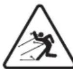
ONACHOCT OJ NCΦPJIHbA!
BHHMaBajTe Ha MoKHN
HcΦpIyBaIbHa MaTePnJaIi
KOnuTo rN npeDn3BnKyBa
IpOTOKOT Ha BO3dyXOT KOuT O
MOKe Da npeDn3BnKaaT TeuKn
NoBpeNi Ha INuca N npeDMETN.
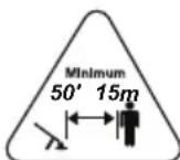
ONACHOCT OJ NCΦPJIHbA!
OdaJeTe Tn CNTe Iua nn DOMaHn JNBOTHN HajMaIky 15 MeTpN DoEka paobTu MaunHaTata!
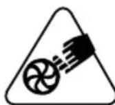
OnachocT oO cKaHaTyBaHBe! CeKoraw dpKeTe rna paTe Te nDaJIeKy OJ peWetkata 3a BNe3 Ha BO3dYxOT. PotOpOT MoKe Da npEIN3BnKA HecpeKNI NOBpeN.

OnachocT od onacn noBpeN!
DpKHe ja obLeKaTa co
JIeaeBN DeIOBn NOdaJeKy OJ
peWetKaTa 3a BJIe3 Ha BO3dyXOT
6ndejKn MoKe Da ce 3aKaun
3a pOTOpOT n da npEIN3BnKa
TeuKN HecpeKn NOBpeN.
OnachocT od onacn noBpeH!
DpKHeTe ja Kocata nOdaJeHy od
peWetHaTa 3a BLe3 Ha BO3dyXOT
6nDejKn MoKe Da ce 3aKaun
3a pOTOpOT n Da npEtn3BnKa
TeuKN HecpeKn NOBpeH.
CoOdBETHO npnbepe te ja Kocata DOKoNHy eDolra.

Jaehnte etnkeTu wTO ce cKHaHe
BAHHO He motaje ro jaheTo 3a naJeHe OKOly paKaTa.
6.3.1 Panahe Ha naIaHNo
3a naJeBe Ha ,NaHNo" Tpe6a da ce n3BePe naJeBe HajmaJnHy no 5
MNHyTN OJ CMnpyBaHBe Ha MOTOpOT HIN NO NOLHeBc RopHBO.
- Inpbo 3anaIeTe ro MOTOpOT cTabajn ja paKaTa 3a perylnpaHbe Ha 3a6p3yBaHOT (cI.4.B) camo do noNoBnHa 'oD.
- Bknyute ro npndyuybaoT, Hocejkn ja paKaTa BO no3nuija «C» (cI. 5.C).
3.ПиТСНЕТоКОЛЧETO3aKOMAнДаТа Ha ypeDOT 3aNotTNKHyBaHBe (cI.5.D)10 nATN 3aДaTRONOTKNHeTe rOpNBOTO. - LbpcTo dpKHeTe ja MaunHaTa Ha TepeHOT npHTnckajKn co eHa paka 3a Da He n3r6hTe KOHTpOla BO TeKOT Ha naJeHBeTo (cI. 6.B).
- Obaa Maunha e onpemeha co EASY-START. Noblete ro konyeTo 3a naIbe co pamHomepeh Noter 6e3 HaJIi DnHexeHa (naIeHeTO ce clyuBa HA kpaJOT od DnHexeTo). Noblete yUTe HeKoIky NaTn Da NOCTnHETe npBnH0 nanehe.
- NocTaBeTe ja KOMaHdaTa 3a npuDySyBaHOT BO nolok6a „B" (cI. 5.B).
- NobleyeTe ro paKoΦaTOT 3a naJeHc ce doKeHa NoCTnHHeTe npaBnHO naJeHBe Ha MOTOPOT.
- OctaBeTe rO MOTOpOT da pa60Tu 1 MInHyTa 3a Da ce 3arpee.
9.Искунуete ja komандараза 3a npduuSyBaHT (cI.5.A), cTabajkn ja paHata BO no3njuA «A» - Dohecete ja paqkaTa 3a perylnpahe Ha 3a6p3yBaOTo (cI. 4.B) Ha MNHmym 3a Da ro ncknyuTe ypeDoT 3a npBnUHO 3a6p3yBaHe n NOCTabeTe rO MOTOPOT BO paOta Ha MNHmym.
BAHHO OOKHy paKofoT Ha jaHeTo 3a NaIeHBe Ce CHNHe Pn BLeYeHBe CO PPHTNCHaT PnDyUyBaU, MOTOpOT MoKe Da Ce 3aDyuH N da ce PpeIN3BnKaAaT NOTeWKOTn Hpn NaIeHBe.Bo Cnyuj Ha 3aDyuYBaHbE Ha MOTOpT (BNDte nacyc 14.5).
6.3.2 NaJIeHbE Ha TOnIa
3a napeHe Ha TOnIIO (BeDHaW no raceHe Ha MOTopoT):
- CnedeTe rTockHte 1-3-4-6-7-9-10 BO npetXoHaTa npoueDypa (cI.6.3.1).
6.3.3 YnoTpe6a Ha pemeHnte
PemeHnte ce cTabaat no naJeHe ha MOTOPOT.
PemeHnte n peMeHnHaTa TpeBa da
ce peryIinaaT corglaCHO BucnHaTa
n roJIeMnHaTa Ha onepaTOPOT.
- Hocete rnpemeHnTe KaKo HopMaJIHN paKN Ha paHeu (cI. 7.A).
- 3aTbOpTe rH KOnuHbTa co CpBeH KInn Ha DeChata CtpaHa N 3a HABpTKaTa.
- OdpKyBajTe rnpemeHnTe Ha Toj NaHH ITO npabHnHO Ke ro pacnopeDyBaat TOBapOT Bp3 paMeHnIte.
- 3a da ja n3dpjNte TeKHaTa Ha ueBkata Ha pa3dyByBaOT, CTaBeTe KOHeKTOp (cI. 7.B) Ha NOTnopaTa 3a paKaTa CO KOMaHnTe (cI. 7.C) n 3akOnJaTe ja CpHaTa ToKa co KInn Ha DecHOTo pAmO (cI. 7.D).
6.4 PABOTA
Bo tehot ha pa6otata, Maunhata Tpe6a cekoraaw Tpe6a da ce dpHH uBpcto co dechata pana 3a paHata co HOMaHdaT (cI.15).
6.4.1 Perylaunja Ha MOKHOCTa
Cekoraaw Tpe6a da ja peryunapate 6p3nHaTa Ha BpTeHe Ha potopot corlacho CO TINOT Ha MaTepnjAnot wTo Tpe6a da ce OTCTpaHn:
- Mala 6p3nHa Ha pa3dYbVbAOT 3a JeCHMaTePnJaN MaNr pMyuKn Ha TpeBHNKOT,
-cpe6a 6p3nHa Ha pa3dYByBaoyT 3a OTcTpaHyBaHBe TpeBa N Iecn Incja Ha acfaNT nnn cBpCT TepeH, - rolemaa 6p3nHa Ha pa3dByBaYoT (HOMaHdaTa 3a 3a6p3yBaOTo e npNTnChata dokpa) 3a NOTeUKN MaTePnJaN KaHo CBEN CHER I ROLEMn r6pnuTa.
6.4.2 Cobetn 3a pa6oTa
Mоже да ѳ рergулпат e no3ицида n 3aнoceнocт aHa paчkaTa co komaнdTe (cI. 3.K) 3a dЯ почигнeTe no3ициJa 3a ydo6Ha pa6Ota. 3a da pergylnpate:
- OtwpaΦeTe ro wpaΦoT (c#. 3.L).
-3a da ja perylnipaTe 3aKocehocTa, CBNTkajTe ja paKaTc co KOMaHdnte HaPpeI nn Ha3aI.
-3a da ja pepynnpate no3njuata, DnkeTe ja Hanpei nn Ha3aD notnpaTa 3a paKaTa. - OTKaKo Ke peryInpate, cTaBeTe rOwpaΦOT (cL. 3.L).
HanpeyBajTe noleKa dpKejKn ro KpaJHnot
IeHa cEbKaTa Ha pa3DyByBaHOT Ha
cooDbETHO pactoJAHne oD Tepenot (cI. 8.A).
3a da n36eHHeTe packpUyBaHe Ha MaTePnJaIOT
HTo Tpe6a Da ce OTCTpaHn, HAcOyTe ro
Mla3OT Ha BO3dYx OKOJy CTpaHnHnTe pa6OBn
Ha HacO6paHnOt MaTePnJaI. HnKorAa He
HacoyBajTe rMna3OT Ha BO3dyXOT KOH
ZeHTapOT Ha HacobpaHnot MaTepnjaI.
BAHHO 3actaHeTe ja MaunHaTa (nacyc 6.5) npu MeHyBaHe Ha loKaunjaTa Ha pa60Ta.
6.5 3ACTAHYBAHbE
7.2.3 IoIroTOBHa H KOH3epBaunja Ha MeuabnHaTa
Ta6eIaTa rN nocOuyBa KOJIuHnHnTe 6eH3nH mAcNo wTo Tpe6a Da ce KOpNCtAe 3a da ja NODROTbInTe MeUaBnHaTae.
Ha cTapeeHe. He noDrroByBaJTe
TOLEMN KOJIUNHn Ha MeuabnHa 3a da ce n36erHe oopmnpaBe TaIor.
BAHHO UyBaJTe rI do6po o6e36eHn I ndHTnФИKByaHn KOHTeJHePte Co MeuabHaTaN CO 6eH3HHot 3a da Ce n36BerHe 3aMeHa BO MOMENTOT Ha KOpNCTeHbe.
BAHHO Od Bpeme HabpeMe YnCTeTe rN KOHTejHePte 3a 6eH3nH 3a MeWbHaHa 3a Da ce OTcPaHaT eBEHTaJIHnTE TaIO3n.
7.3 NOJHEHe TOpNBO
I IOnHeBeTo rOpNBo ce n3BpUyBa Hora MaunHaTa He pa60Tu co N3BaDeHO hanae Ha CbeHnHaTata.
PpeI noJIhe:
- PpoTpeCeTe ro eHepnUHo pe3epBOaPoT 3a MeuBaINHa.
- NocTabete ja MaunHaTa Ha pamHa NOBpUnHa, BO Cta6nHa No3nJa co KaNaYeTo Ha pe3epBoapOT 3a MeuabHnHaTa OJrope.
3A6EJELHA Ha KaNayeTo 3a pe3epBoapOT 3a MeuabHnHaTa (CJ. 11.A) ro nMa cIeHNOT Cm60J:
Pe3epBoap 3a MeuabnHa
3.Исунштete ro Kanayeto Ha pe3epBoaopTO BO Kpyr 3a Da ce N36erHe HabIeRyBaHBe HeuNCTOTn npn NOHeBTo.
4. OTBOpTe Ro BHIMaTeJIHO KaNAcYeTo Ha pe3epBOApOT 3a MeWAbINHa 3a Da ce HcnyuTn PnNTUCOKOT NOCTeNEHO.
5. HanoJIHHeTe CO INHka N He CTaBaJTe OMeuABHHata Do rPNoTo Ha pe3epBoapoT.
7.4 YNCTEHE HA MALINHATA H HA MOTOPOT
3a da ro hamalnte pnsikot od 3anaIyBaHbe, odpxybajTe rMaunHaTa, a oOcboHO MOTOPOT 6e3 octaTOUo JNCTOBn IpaHKn.
- CekoraawuHCTeTe jaMaunHaTaNo ynoTpe6aTa co uHcTa H MOKpa Kpna NOTOHeBA HO HeyTpaleH DeTePeHT.
OTcTpaHeTe rncnte TpaHnHaBlaRa co MeKa n cyBa Kpna. Blarata ocTaba npocTop 3a pN3NK oJ eJeKTHpuH yap.
He KopncTeTe a6pa3nBHN DeTepeHTn n pactbOpyBaun da rH nCCHNTe PnaCTnHnTE DeIOBN nn paKnTe.
He noIeBajTe BODa n H36erHyBajTe MoKpeHBe Ha MToPOT N Ha eJeKtpuHnTe DeJIOBn.
OdpkybajTe ro potopot cekoraw nCT od npaunHa n octatooun konwto ce pa3dyBaIe co BO3dYxOT KOH peWetKaTa. He npckajTe ro potopot co Boda.
3a da n36erhe Te nperepeBaHe nIu OwTeTyBaHe Ha MOTOpOT, cekoraw npOBepyBaJte DaJIne peWeTkata 3a BO3dYx 3a IaJeHe e YnCTa N 6e3 OCTaTOU.
7.5 HABPTKINIUPAΦOBN 3AΦHKCIPAHB
CnTe 3aBpTKn, HABPTKN IIOCTOBN ODPKByBajTe rN COoDbETHO 3aUbpCTeH N 3a Da CTE CNpyPHN deHa KocayKaTa e 6e36eHa 3a pa6Ota.
- PeoBHO npOBepyBajTe daHn paKnte ce ubpcTo fHKcapaHn.
8. BOHPEДHO OДРЖУBAHБE
8.1 YNCTEHe HAcHJTEPOT 3A BO3dYX
BAHHO YnCTeIbeTo Ha nITepOT 3a BO3dyx e bHTHO 3a do6pa paOta N BeKOT Ha cAmata MaunHa. He paOteTe 6e3 nTep nn CO OwTeTeH nTep 3a Da He npEn3BnKaTe HENOpBaINbN OwTeTyBaHa Ha MOTOPOT.
YnCTeHBeTo Tpe6a da ce cnpoBeyBa ceKo8-10 yacobn pa6ota.
3a YnCTeHe Ha HnTepeoT:
- OtupaTeTn DBeTe KOnHbA (cI. 9.A) n n3BaTeTo KaNaKOT (cI. 9.B).
2.ИЗвадеTe ro ФиntepoT oД xaptnja (cI. 9.C)и ФиntepoT oД cyнrep (cI.9.D).
3.ИЗдуВajTe ro ФиNTepOT od xapTnja 3a Да Г OTCTpaHnTe HeuNCTOTnJaTa n OCTaTOUHTe (cI.10.A).
4.Исnéретe ro Фиntepot oД cyнгep co bOda (cI.10.B).
BAHHO He KopncTeTe 6eH3nH, dTepeRHT nn npyro cpeCTBO 3a uNCTeHe Ha nTepoT.
5.OCTaBeTe ro fHITepoT oC cyHrepe Da ce nCywn Ha BO3dyx.
6.ИсунштeteTo MeCTOTo 3aФиNTepOT OД HeunCTOTnN, OCTaTOuN IγБpe.
7. coCTaBeTe ro eIeMeHToT CO ΦnITpnte Ha CBOeTo MecTo (cI. 9) (npOBepTe dAni iΦnITepoT oD cyHrepe y6aBo nCyuWeH);
8. CTabete ro kanaeTo (cI. 9.B), fHKcapajTe rKoNCHbata (cI. 9.A).
8.2 KOHTPOJHA CBEKNHATA
Do cBeKeHcKaTa (cI. 9.G) ce npncTanyBa Kora Ke ro n3BaJnte KaNaHeTo (cI. 9.F).
CbeHnHaTata Tpe6a da ce 3aMeHN co dpyra co aHaIorHn KapaKTepnCTNKn BO clyujkora eJeKTPoDnTe ce nperopeHN nn HnpabnHO nOJnpaHn, nn Ha ceKo100 yaca fynKUnOHpaHe.
Pa6oTHe Ha CBeKnUHaTa rH N3BEdyBa npOdaBaOT HnCneuJaIln3npan cepBnCeH ceHTap. PpOBepTe ja Ta6eJaTata 3a ODPKByBaBe H Ta6JaT aN DeENTnФKaunja 3a COODBeTHHe NTHePBeHcHn Ha CBeKnUHaTa.
8.3 JAAHE 3A PAJIHeBc
3aCTaHnKoT Tpe6a Da ro CmEH jaKeTo 3a NaIeHe npn npBnTe 3Haun Ha OwTeTyBaHbE.
8.4 PEGYJALAUJHA HA KAPBYPATOPOT
Kap6ypaTopoT ce perynpa BO phapnka BO peKIM Da daBa MaHcImaJIHn pe3yIITaTH BO cekOja CNTyaunja Ha KopncTeHe, CO MHNmAJHO EMNTnpaBe Ha UTeTHN rAcOBn IN BO CORlaCHOCT CO BaKeYkIne 3aHOH.
Bo clyujaHa lowa n3Be6a, o6paTeTe ce kaj 3actanHnKOT da rnpOBepn Kap6ypaTOPOT N MOTOPOT.
Perylaun Ha KapbypatopoT:
T = perγηλιαύηνι ΜΑ ΜΗΗΜΥΜ
L = perylaunja ha rohpBTo npMaIa cIIa
H = perylaunha ha ronboto npn rolemacna
9. OДЛоЖУBAHБE
BAHHO Be36eHCHHTe MePKu WTO
Tpe6a da ce cIeJaT BO TeKOT Ha paKyBaHc ce HabeJeHN BO nac. 2.4. Ctporo npnDpyBajTe Ce do Tne yNaTCTBa 3a da n36BerHeTe cepNo3HN pN3uN NIN ONaCHOCTN.
9.1 OJIOHcyBAHbE HA MALINHATA
AkoHema da ja KopnCTnte MaunHaTa NOBeKe od 2-3 meceu, Tpe6a Da ce npImeHaT HeKoJy peweHja 3a Da ce n36erHat NOTEKOTn pni OShOBvBaHe Ha pa60tata nn TpaJH OwTeYBaHa Ha MOTOpOT.
PpeoJanaheHaMaunHata:
- Hcnpa3HeTe ro pe3epBoapOT Ha OTBOpeHO KORA MOTopoT e CTydeH.
- OctaBeTe ro MOTOpOT da pa6oTn Ha MINHmym DoJeKa He COropu ZeIOTO ROPIN BO ITO OCTaHaNo BO pe3epBOapOT n BO Kap6ypatopOT.
- Octabete ro MOTOPOT da ce n3naI.
4.Исунштete ja TeMeJIHO MaUNHaTa. - Поберете далл деловпес pa3la6abehи nln OwTeHn. Ako e notpe6ho, 3ameheTe rOswTeHNTe DeLOBn n 3aTeHETe rpa3la6abehnte wpaФOBn n Habrtkn nlin KOHTaKTHnpajTe co OBlaCTeH cepBvcep.
- Ondoxte ja MaunHaTa:
-BO cyBa npocTopnja,
-3acOJIHeTa OJLOUIN BpeMeHcN yCIOBn
-иHaMeCTOHaBOPoДоФaTOTHaDeuTa.
- yBepyBajKn DeKa CTe rN TprHaJIe KnyeBNTe N OnpMaTa wTo ja KOpNCTeBTE npn OdpKyuBaHbeto.
Kora tpeba da ja 3anaIte MaunHaTa:
- IodrotBeTe ja MaunHaTa (nornaBje. 6).
10.ДВИЖЕΗΝΤΡΑHCΝΟPT
Cekora kora e noTpe6en npenoc nItnpaHCnopt Ha MaunHaTa noTpe6Ho e:
- 3acTaHete ja MaunHaTa (nacyc 6.5).
-Поуекajтда застане роторот.
-OTcTpaHeTe ro KaNaYeTo Ha CBeKnKaTa (cI.9.G).
-- da ce faTn MaunHaTa cAmo 3a paKnte n Da ce HacOyat ueBknte 3a Da npetCTabyBaat npeuKa.
Kora ja Hocnte MaunHaTa co Bo3nlo:
-ИЗБаДTe Ги цБКИТe,
-06e36eTe ja COOBeTHo MaUNHaTa co NOMOW Ha jaXnHb a Hn CnHnnp,
- nocTabete ja Ha NaHH da He npetCTaByBa onaCHOCT 3a HNKoro.
11. ПOMоши ПОпРавКА
Oba ynpaTCTBO rH npTeCTaByBa cHTe HeonxODHN INDnKaun 3a ynpaByBaHe CO MaunHaTa n 3a npaBnHO ODPKByBaHe wTo rN H3BpUyBa KOpNCnKOT. CnTe INHTepBeHcN 3a peYnaJia n ODpKByBaHe wTo He ce ONnShaHn BO OBA yNaTCTBO Tpe6a Da rN CNPOBeDe 3aCTaHnKOT nIi CneuJaIIN3npaH cepBnCeH cENTap 6nDejKn 3HaAT KaKO n rN IMaat HEONXODnTE INHCTpyMeHTn CO KOHIto pa6oTaTKe ce 3aBpUn npaBnHo,
3eMajnroBO npedBnnpBo6nTHnoT cTepeHa 6e36eHocN yCIOBHTe Ha MaunHaTa. Cnte onepaunTo ce n3BeDenHa HecooDBetEn HauHH oN HeKBaINΦnkyBaHN Iuca npDOHeCyBaat Da ce N3r6bN Cekoja φopMa Ha rapaunjia n CeKOJ obnK Ha O6Bpcka Ha npOn3BOAnTeIOT.
- Camo OBlaCTeHnte cepBnCH 3a NOMO MoKe Da rN n3BpUyBaat nonpaBKnTe N OdpKyuBaHbeto wTO ce NOr rapaHcNiJa.
- OblacteHTe cepBnCHn ceHTpn KOpNCtata camo opunHaJIHn pe3epBn DeIOBn. OpunHaJIHnTe pe3epBn DeIOBn n dOJIoHNteJIHa ONpeMa ce cneuJaIHO dN3ajHnpaHn 3a MaunHaTata.
OpHnHaHnTe pe3epBn DeIOBn IOnOJIHnTeJHa ONpema ce CneuJaIHO dN3ajHnpaHn 3a MaunHaTa. - Pe3epBHNTE DeIOBN I DOJONHITeHaTa ONpema KOnsTo He ce ODo6peHn, yNOTpe6aTa Ha pe3epBHN DEIOBN I DOJONHITeHa Na Onpema KOnsTo He ce OPnIHnAHn Ja HapyuBaat 6e36eHOcta Ha MaunHaTa N I GocObOyBa IPOUN3BOIDTeIOT Oc KeoJa 06BpCKa INN OdROBOPHOCT.
- Ppenopaybame da ja odheceTe MaunHaT ABOOBlaCTeH cepBnCeH ceHTap ceHOjnat Kora Tpe6a da ce pa6OTn Ha ODpKyBaHe, nonpaBka nn npOBepHa Ha 6e36eHNoCHnte ypeN.
12. ONCEI HA IAPAHUNJATA
Iapaanjata ngnokpnaCnTe wTeHa MaTepnjAInTe n npOn3BODCTBOTo. KopncnKOT Tpe6a BnImaTeJHo Da rN CJIeDn CnTe yNaTCTBa KOn ce daJeHn DO npNoJKeHaTa DOkymeHTaunja. Ipaanjata He ngnokpna WTeTnte HactaHaTH 3aToa wTO:
He cte ce 3ana03haIe co npnIOKeHaTa DOkymeHTaunja.
He CTe BHNMaTeJIHn.
- YnOtnpe6aTa mOHTnpaHbeto He ce npaBnHN nKOH3NCTeHTHn.
- Ce KopncTaT pe3epBn DeJIOBN KOnuTo He ce opHnHaJIHn.
Ce KopnCTn DoOpHnTeHa onPema Koja He e ODo6peHa HHTy DOCTaBeHa OD pON3BODnTeJOT.
Гаранцида He noKpnuBa n:
HopmaHOba6eHeHa nOTPOUHNTe MaTepuJaJI.
- HopmaJIHo a6eHbE.
KnybauoTe 3aHTnTeH CO COOBETnTe
DpKaBn 3aKOnn. PpaBata Ha KyuBaOY
KoN Ce npeDbNdeHn BO DaJeHnTe
DpKaBn 3aKOnn Ha HneDeH NaHH He
ja JIMMtnpaat Obaa rapaHcnuJa.
13. TÁBÉJIA 3A ODPKJYBAHbE
| Иntервенциja Пераюпасус | ||
| MAШИHA | ||
| Контуна на сите сножни | Пред сени щог趟ба 7.5 | |
| Бezбedingши Контrolл /proверka на komандITE | Пред сени щог趟ба 6.2 | |
| Општо чисné и Контrolla | На кра jot на сени щог趟ба | 7.4 |
| MOTOP | ||
| Контуна/данување горово | Прead сени щог趟ба 7.3 | |
| Општо чисné и Контrolla | На кра jot на сени щог趟ба | 7.4 |
| Чисné на силтерот за Воздун | 8-10 ча / no сени щог趟ба | 8.1 |
| Чисné на с被执行�а | 10 ча / no сени щог趟ба | *** |
| Замена на с被执行�а | 100 ча / no сени щог趟ба | *** |
** Pa60Ta 1to Tpe6a da ja n3BeDe 3acTaNHHKOT nIi CneuJaIIN3npaH ueHTap 3a cepBnCnpaHe.
14. HECOO dBETHA PABOTA
| HAJDEHA MOXHA Плични PMUHNA PELSEHNE | ||
| 1.МOTOPOT He ce пали плел палк He можеда сe CTABN BO DBNXHEBé | Плоцураета на палеше He e npabunla | Следete Гу уразства (nacyc 6.3). |
| Сveкунka差别 e чьоста плел оданеочность Meу ЕLEKTPOДITE He e toyna | Проветe ja сveкунka差别 (nacyc 8.2). | |
| ФИLTERTOT 3a BOZdux e 3aTHAT ИСЧNTe | Te roи / пали заменete ro ФИLTERTOT (nacyc 8.1). | |
| ПрobLEMи co coropubaÎe Контактра | Te co OBlaacteh сервисн цentap | |
| 2.МOTOPOT ce пали,но co мала мойност | ФИLTERTOT 3a BOZdux e 3aTHAT ИСЧNTe | Te roи / пали заменete ro ФИLTERTOT (nacyc 8.1). |
| ПрobLEMи co coropubaÎe Контактра | Te co OBlaacteh сервисн цentap | |
| 3.МOTOPOT habotni небравино пали нема моь вр ontobarvbaÎeTo | Сveкунka差别 e чьоста плел оданеоч塗а Meу ЕLEKTPOДITE He e toyna | Проветe ja сveкунka差别 (nacyc 8.2). |
| ПрobLEMи co coropubaÎe Контактра | Te co OBlaacteh сервисн цentap | |
| 4.МOTOPOT ИСРУТа повке чад | Ималу талози od мешавина Толоте | Te ja мешавина сюpeд, уnatCTBOTO (nacyc 7.2). |
| ПрobLEMи co coropubaÎe Контактра | Te co OBlaacteh сервисн цentap | |
| 5.ЗадшуваÎe нам MOTOPOT | РачКATA 3a палеÎe ce аNTINВIPA reноклу пати co Внлухен пinduyшвач, | Изваде tee ja сveкунka差别 (nacyc 8.2) и nobilete ja BнIMATEЛно рачКATA ha jaheTo 3a палеÎe (cI. 6.A) за го eIJIMINHPaTEпrelумерно rorpINO. ПOTOA, Incшete Гу лесгосте на сveкунka差别 и поставе ja на мOTOPOT. |
| 6. POTOPOT ВRTN, Но BOZduxOT He илjetува OddzEBKATA на pa3dvyBaVbAOT | Цевкata Na pa3dvyBaVbAOT e блOKИрANA пILs 3aTHATA | З actanete ja машина и trgHete ja пукhalata. |
| 7. Има БUCHAVa И/PAL пөнүмэрп ВИбраши Во TEKOT Ha pa60Tata | РаЗлабавени пIL oштeteи DeLOBи 3a | претe ja машина и ИЗваде tee ro kabelot od Сveкунka差别 (cI. 9.F). Проветe далу Има оштетувы; Проветe далу DeLOBи te ce pa3lalabaveni 和 3aterHete ГI Изв�е tee Гу п罗berknite, заменite пIL порrabknite Bo ABTOPI3Hirpanцentap. |
| 8. Машина удрилva BO стану predecessor | ОштетуваÎe пIL рэлабавени DeLOBи | Зретe ja машина и ИЗваде tee ro kabelot od Сveкунka差别 (cI. 9.F). Проветe далу Има оштетувы; Проветe далу DeLOBи te ce pa3lalabaveni 和 3aterHete ГI Изв�е tee Гу п罗berknite, Заменite пIL порrabknite Bo ABTOPI3Hirpanцentap. |
| 9. Машина Испшta чад BO TEKOT Ha pa60Tata | РаЗдуВвaYOT e oштeteи. He kORISCTe | te ja машина. ВEDmaI З actanete ja машина, ИЗваде tee ro kabelot od Сveкунka差别 and obparate ce Bo cepBicen hцentap. |
KoHTaKTnpajTe co 3acTaNHKOT 3a NOMO aKO npo6IeMnte oncTojyBaat OTHaKO cTe rHn HapabInle RopenocOeHnte onepaun.
INHOUDSOPGAVE
- ALGEMEEN 1
2.VEILIGHEIDSVOORSCHRIFTEN. 2
3.LEER DE MACHINE KENNEN 5
2.5 BESCHERMING VAN DE OMGEVING
7.5 MOEREN EN SCHROEVEN VOOR BEVESTIGING
- EKSTRAORDINÄERT VEDLIKEHOLD 11
2.4 VEDLIKEHOLD, LAGRING
7.3 ETTERFYLLING AV DRIVSTOFF
13. VEDLIKEHOLDSTABELL
2.2 CZYNNOSCI WSTEPNE
6.1 CZYNNOSCI WSTEPNE
- MOHTAH 7
4.1 KomnoentbI Jn MaHTaHa 7
5.CPECTBAYPNPABJEHNA 7
5.1 Pbyar ynpaBHeHnI npocSeHem 7
5.2 Pbyar peryIaTopa IpocceI N ocTaHOB DnurataTeI . 7
5.3 Pbyar ynpaBHeHnBaO3dyuHOn 3acNoHKn ..8
5.4 HONka ynpaBHeHnHaCocOM noKaHKn TOnJIbBa (IpaMep) 8
5.5 RykoTka pyuHoro 3anycka.. 8
- 3KcPJIyATAUIMMAUINHbI
6.1 PpeBapnteIbHbIe onepaunn.. 8
6.2 IpoBepKn 6e3oNaChocTn 8
6.3 3anyck 9
6.4 Onncahne pa6oTb1 10
6.5 OctaHOB 10
6.6 Pocne pa6oTbI 11
- ПИАHOBOE TEXHINUECKOE OBCJYKINBAHINE 11
7.1 O6uie cBeHnna 11
7.2 PnHrToBLeHne Cmecn 11
7.3 3anpaBka TOnJIbOM 12
7.4 OuHCTKa MaunHbI n DnBraTeJIa 12
7.5 KpeenKhble raikn BNHTbl 12
8.BHEOUEPEHHOE TEXHHUECHOE OBCJUYKUBAHNE. 12
8.1 OuNTka BO3duyHoro 0nIbTpa 12
8.2 PpOBepKa CBeu 13
8.3 PycboB Tpoc 13
8.4 PerynilpoBka Kap6opatopa 13
9.XPAHEHIE 13
9.1 XpaHeHne MaunHbI 13
10.IPEMELEEHNEITPAHCNOPTNPOBHA.14
11.CEPBHCHEO OBCJYKINBAHNEI PEMONT...14
12.YCJIOBNAI IAPAHTIN 14
13. TABJIULA TEXHNUECHOO OBCJUYKINBAHIN 15
14.BbIIBJIENHE HENOLAOK 15
1. OBUNIE CBEDEHNA
1.1 HAH CJIeIyET YITATb 3TO PYKOBODCTBO
B TeKCTe 3TOrO pyKOBOcTBa OTdJIbHbIe naparpaΦbl, codepkaune Oco6eHNO BaJHyIO INΦOpMaUIO TExNKe 6e3OnaCHOCTn IIN npINCuINax pa6oTbI yCTpOiCTBa, BbIJeJIeHbI CJIeDyUOuM o6pa3OM:
INPMEYAHNE BAXHO
CopeKHTyOHTHeHnIINCCBILNHa
Apuyo paHee yOnmHyTuO HOpMauno
IpeDOrbpaueHnIOLOMKn
MaunHbI INn HaHeceHnYuep6a.
3HaK yKa3bIbAeT Ha onaCHOCTb.
Heco6JIHOeHne daHHoro ppeDynpexKeHnmaKet npINBeCTN B NOJyueHnIO n HaHeceHnTOpaBM N/nnn HaeCEHNO yuep6a.
IyHkTbI, 6oPamJIeHHbIe cepoI NyHKnHpHOJ
paMKo, coepKHaT OINcAHne OINcHOHaJIbHbIX
XapaKTepnCTNk, He npncuix BCem
MOeJIaM, PpeDCTaBLeHHbIM B DaHHOM
pyKOBoODCTBe. IpoBepbTe, ecTb IIN daHHa
XapaKTepnCTNka B BaWei MoDeJI.
Bce 603haeHn "peepHn", "3aHn", "npabb" n "IeBb" yka3bBAIOCTc OTHOCHTeIbHO pa6oero noIoJHeHn onepaTopa.
1.2 OBO3HAUEHNA
1.2.1 PucyHKn
PncyHKn B daHHOM pyKOBoODCTBe
no 3KcNpyaTuNn npOHymepoBaHbI
1,2,3 n TaK daJe.
KomnoHeTbI, NOKa3aHHbIe Ha pncyHKax,
603NaueHbI 6yKBaMn A,B,C n TaK daJe.
CcbInka Ha KOMNoHEn T C Ha pncyHKe 2
OcyuEcTBJAreTC npn NMOUg Phpa3bl:
"CM.pnc.2.C" nn npocTo "(pnc.2.C)".
N3O6paKeHnHa pncyHKax YBJIOTcR
npn6n3nteJbHbIMn.PealhbIe DeTaII
MOrTy OTnNuATbcr OT N3O6paKeHHbIX.
1.2.2 Ha3BaHnIgJaB
DaHHepyKOBOIDCTBO NOdpa3deJIeTcH naIaBbI NnyHKTbI. NyHKT NOD Ha3BaHnEM 2.1 O6yHeHne" YBnETCN NOdnyHKTOM rIaBbI 2. IpaBnla 6e3oNaChOCTN". CcbIkn Ha rIaBbl NnyHKTbI 0603HaiaOTcKOpaeHEm I.II NpYHKT N COOTBeTCTByIOUcIM HomepOM. PnpMep: "rI. 2" nII "nyHKT 2.1".
2. ПAPВILA BE3ОПАСHOCTN
2.1 OByeHne
O3HaKombTecb c opraHm ynpabIeHHn HnHaJIeHaaHm nCNoJIb3OBaHHem MaunHbl. Hayntecb 6bICTPO OCTaHaBnBaTb MaunHy. Heco6JIouHeHne Mep npedocTopOHHOCTn H peKomeHdaaN MoKeT npNBecTH N noHapam HnHn cepBe3HbIM TpaBMam.
HnB KOeM Clyuae He pa3peWauTe NOIb3OBaTBCa MaunHOJ DeTAM NIN LInzam, HeIOCTaTOUHO XOPOwO 3HaKOMbIM C npabNlAmn O6paueHnC Hei. MeCTHOe 3aKOHOdAteJIbCTBO MOHeY UcTaHABUNBaTb MHNImaJIbHbI BO3pact NOL3OBaTeJIa.
- HnKOrda He nCnoJIb3yIte MaunHy, ecIn noJIb3OBaTeJIb yCTaJI, IIOXo Ce6a CyVBCTByeT INn HaxOJNTcI NOI BO3DeIcTBHeM JeKapCTB, HApKOTnKOB, aIKORoJIr INn BeIeCTB, CHNJaIOUx CKOpOCTb peΦJIeKCoB IN yPoBeHb BHIMaHn.
-ПOMHHTe,чToОпаТорилNoь3OBaTeIb HecET OTBETCTBENHOCTb 3a HeCuaCTHbIe ClyuAn IIN yUep6,HaHeceHbIyDpyrIM LIncAm IIN INx IMUyeCTBy.ПOLb3OBaTeIb HecET OTBETCTBENHOCTb 3a OueHky NOTeHuaJIbHbIX PnCKOB Ha yUacTKe,Ha KOTOpOM OH pa6OtaE,T,KpOME TORO,ONdoJXeH npINrTa BCE MepblnpEOCTOPOXHOCTN, YTObI OBeCneHTb CBOIO 6e3OnaCHOCTb N 6e3OnaCHOCTb OKpyKaIOuX, BOCo6EHHOCTN Ha CKLOHaX,HEPOBbIX,CHOJIb3KHX IIN HeYCTOuHBbIX NOBepXHOCTx.
- EcIn Bbl HamepeHbI nepeDaTb nIN OdoJHKITb MaunHy dpyHM IucaM, yOCTOBePbTECb, YTO OHN O3HaKOMnJIncb C yKa3aHnMa N0 3KcNlyaTaunn, n3LOXHeHHbIMB HaCToAeM pyKOBoDCTBe.
2.2 NOДΓΟTOВNTeJIbHbI E ONEPAUIN
CpeDCTBa HndnBnDyalbHo3aunTbI (CN3)
HaIeHbTe nOxOaJyU OJeKdy, npOHyu paOoYIO oSyBb Ha HeckoJIb3aJeu NpOoWBe H dInHHbIe 6pIOKn. He 3anyckaIte MaunHy
6OCHKOM HIN B OTKpbItbIX CaHdaJIHX.
HaedeBaIte HayuHnKn IJRA 3aunTbI opraHOB
cLyxa, npOTNBOBn6paUHOHHbIe nepaTHN,
3aunTHbIe OChN, nbJIe3aunTHyIO MACKY.
- 3Ta MaSiHa pa6oTaet Ype3BbUaHNo UyMHO Tpe6yeT NcNoIb3OBAHnI 3aUHTbIX npncnoc6JIeHn IJr opraHOB clyxa.
IcnoJb3OBAHne 3aunTbOpraHOB clyxa MoKET CHN3NTb CnOC6HOCTb CJIbIaTb npedynpexdEHHa (KpHKn HnI abapnHbIe cnHaJI).YdJeIte Oco6oe BHNMaHne npoCXODAeMy BOKpyr pa6oyero yactka.
He HadeBaIte 7apfo, xaIaTbI, KOJIbe, 6paCJIeTbI, pa3BeBaIOUyOcra ODeJdy, a TaKHe ODeJdy CO UHypKaMn IraIcTyKn, a TaKHe IIOBle BnCraYne NInu ShIpOKHe akCeCCCyApbl, KOTOpBle MOryT 3acTpRb B MaINHe NIN B ppeMTeX n MaTePnaJax, HaxOJaUxNcra Ha pa6Oyem MeCTe.
-Должнblmобра3OMco6epnteДИHHHbIe BOLOcbl.
Pa6ouy yuactok / MaunHa
BHHMaTeIbHO OCMOTpHrE BeCb pa6OHy uactOK n BpyHyU, C NOMOuBIO rpa6eJIb Hm MeTbI, pa36epHTe OTXoDbI n y6epHTe BCE, YTO MOKeT 6bITb OT6poUHeO MaunHOi (KOrda OHa npIMeHReTcB KauEcTBe BO3dyXoDyBKn), IIn60 3acOpHTb Tpy6y BCacbIBaHNr (KOrda OHa npIMeHReTcB KauEcTBe nbIeCocA) IIN CTaTB HCTOCHNkOM ONaCHOCTn (KaMHN, BETHN, pPOBOLOHa, KOCTn n T.D.).
- Ecni 3emIy nIbHna, peKOMeHyeTcI CJIerHa CMOHTb NOBepXHOCTb.
AByraTeIN BHyTpEHHero CropaHn: TOnnIBO
ONACHOCTb!BeH3HHcMecbJeERKOBOCNJIaMeHrIOTC.
ONACHOCTb!ToJIHBOJeERKOBOCnlaMeHReTcR.
XpaHnTe 6eH3nH n CmEcB CneuaJIbHO npEHa3HaueHHbIX DnA 3TOrO KaHnCTpax, OMOIOrnpoBaHHbIX DnAHHo YeN, B 6e3OpaCHOM MeCTe, BdAnOT HcToUHKnOB TeIIa N OTKpbITOrO PnAmEH.
OuHuaTe KaHnCTpbI N MeCTO XpaHEnHr TOJIINBa OT OCTaTKOB TpaBbl, IInCTbeB IN3JIINKOB Cma3KN.
He ocTaBnIte KaHnCTpbI B npedeJax DoCraeMoCTn DeTei.
He kypnte BO Bpem npnroTOBlena CmeCn, BO Bpem 3anpaBKN HIN DOJNBKN TOJINBa,a TaKHe BOO6e npn o6paueHn c ToJINBOM.
3aIINBaIte TOnJIInBO Yepe3 BOpOHky, TOJbKO NOI OTKpbITbIM He6OM.
- 136eaiTe BdbixaHna napOB TOnJIbBa.
HeIobAJIaIeToTOnJIbBOHHeCHImaIte npo6Ky 6aKa, KOrdaDbIrataTeIb pa6Otae nnKOrda OH rOpAyn.
- MedlenHNO OTKpoIte npo6ky bKa, YTo6bl NoCTeNEHHO c6pocHTb BHyTppeHHe DaBJeHHe;
He npn6lnkaTe nlaMra K 3anpaBOCHOMy OTBepCTNUO 6aHa, YTO6bl npOBepNTb erO codepxHMOe.
B clyuae pa3nBa TOIINBa He 3anyckaTe DnraTeIb, y6epnte MaunHy C MeCTa pa3nBa TOIINBa I npIMnte Mepbl No pdeynpeKdEHNIO BO3rOpAHJa Do Tex Nop, nOHa TOIINBO He nCnapITcN ero napbHe pacceOTc.
HemeIeHNO y6epnte BCE cIeIbI TOIIBA, KOtOpoe npOJIIOcB Ha MaunHy nn Ha 3eMIO.
Bcerda Bo3BpaaJaTe Ha MeCTO nIIOTHo 3aKpyuBaJTe np6Kn 6aka n KaHnCTpbIC TOnJIbOBm.
He 3anyckaIte MaunHy B MeCTe 3anpaBKn; 3anyck Dniratela Heo6xOIMO OcyuecTBnTb Ha pacctOarHn He Mehee, Yem 3 MeTpa OT MeCTa 3anpaBKn TOnJIHBOM. - I36eraIte KOHTaKTa TOnJIbBa C OeJdoi n, B clyuae ee 3aqr3HeHnI, nepeOeHbTeCb nepeD 3anyCKOM DBrIraTeJI.
2.3 BO BPEMRAPOBTbl
Pa6oynyuaCTOK
He BkIouaTe DBNrAteJIb 3aKpbITOM npoctpaHCTBe, rDe MOKeT CKONITbcr OAnChbIyrapHbI ra3.3anyck DOJKeH pOn3BODHTcRa yIuue HIN B XOpOo NPOBeTpBaEMOM MeTe. He 3abBaIte O TOM, YTO BbIXIONHbIe Ra3bl DBNrAteJIr TOKCnHbI.
Bo Bpem 3anyka MaunHbI He HnpaBnIte TnyuNTeBn, CJeDoBaTeJbHO,BblXIoNHe Ia3bl Ha JeRKOBCnJaMeHrOUsneCmATEpHaJIbI.
He nCnoB3yIte MaunHy BO B3pbIOOanacHOn cpeDe, N6bN3OCTn OT rOpUChX HnIDKOCTe, ra3a nn PbIn. 3JeKtpnueckne KOHTaKTbI nn MExaHnueCKoe TpeHne MOyT CReHepnPOBaT bNcPbl, KOTOpbl E MOyT npNBecTn K Bo3rOpaHnIO PbIn nn NapOB.
- HNKOrJa He nCNoJIb3yIte MaUHHy B 3aKpbITOM NOMeUeHN, Prn HaIuHn IcnapeHn, BO B3pblBOOnaCHO cpe, a TaKHe NO6JIH3OCTN OT JeRKOBCnlaMeHraIOxxCr MaTePnaIOB N 3JeKTpoo6OpydoBaHn.
Pa6oTaIe ToIbKO npn DHeBHom CBTe Hnn PpN XOPOWe NCKyCCTBeHHOM OCBeUeHIn, B YcNoBnX XOPOWe BNIMOCtN.
Ha pa6ooyem yuaCTke He doJHKHO 6bITb B3pocIbIX IIOdei, DeTeH N HKBOTbIX. Heo6xoJIMO, YTO6blpyroB 3pocJIbIy eJIOBEK CMOTpeJ 3a DeTbMn.
- Поберьт,чTo Дугп Люн HaxояТс
Ha paCCTOЯHи, NO MeHbWei Mpe, 15
Мет探测 ot paDnUca pa60TbI MaunHbl.
- H36eraIte, NO BO3MOxHOCtN, pa60TaTb Ha MOKPOH ININ CKOJIb3KOH NOUBe, ININ HA IIO6OHN KpyTOH ININ HEPOBHO NOBepXHOCTN, He OBeCneuBaIOUeY UCTOUYBOCTN OepaTopa BO Bpemr pa60Tbl.
- I36eraIte pa60TbI Ha MOKpoi TpaBe, NOd DOxHem NnNecn 6JIn3NTcRrpo3a, OCO6eHHO eCnn BO3MOXHbIMOLHN.
- O6paaTe oco6oe BHNMaHne Ha HepOBHOCTn NOyBbI (Kouch, KaHaBbl), Ha yKIOH, Ha cKpbITbIe ONaCHOCTn I HAJIYue BO3MOXHbIX PpeTCTBNI, KOTOpbIE MOrYT OrpaHnHTb BNIMOCtB.
- CobJIOdaIte oCTOpOHHocTb, pa6oTaI pIaOM c
- O6pbIbAMn, KaHabAMn I 6pePam N BDOeMOB.
- Bcerda yuHtBbAaTe HnPaBJIeHne Betpa
- HNKoIgDa He pa6OtaIte npOTNb Betpa.
He nCnoJb3yTe MaunHy no6n3OCTOn OT OKpbblbIX OKOH.
Bo Bpemr nCnoJb3ObaHnna 36eraIte CKoJIeHnna NOdHrTOrO C 3eMn MaTePnAJa B 30He BbIbPoCA, NocKoJIbky OH MoKeT nonaCTb BO BCacBbIAuUne OTBepCTn. - Korda Bbl pa60TaTe Ha MaWHe prdOm C npoe3KeJ yactbO, yuHTbIbaTne NOTeHuaJIbHOe npcyTCTBHe TpaHCnOpTHbIX cpeDCTB.
-Bo n36eJHHe noKapHoN onaCHOCTn, He octabIaIte MaunHy C TOpRyIM DBrIaTeJIeM CpeIN IInCTbeB,CxOHTpaBbI IN DpyrNX JeRKOBCIIaMeHIOUxxCMaTePnaIob.
IpaBnla nobeHnBa BpeMa pa6oTbI
Bo Bpemra60bB KaueCTBe BO3dyXoYbHN Heo6xoJIMo Bcerda npouHOn ydepHnBaTb MaunHy npaBOy pKoHa BepxHe pyKoTHe.
BoBpemra60tbiB KaueCTBe IbIeCoca (ecn3To npedymoTeHo) Heo6xOIMO Bcerda npouHO ydepHnBaTb MaunHy o6enmPyKamn, npabar pyKa DoJnHa HaxOHTbcn Ha BepXHeN pyKoTKe, a JEBa-Ha HnKHei pyKoTKe, npn 3TOM KOHTeHep DoJHHeh HaxOHTbcn CJIeBa OTonepaTopa.
- PpIMnTe yCToHnBOe n npOuHoe nolOKeHne, n CO6JIHOaIte oCtOpOxHOCtB.
- CoxpaHryTe paBHOBeCne.
- H36eRaTe CnIbHbIX yIapOB O NOCTOPOHHe npEaMeTbI N yUHTbIBaIe TBepoTHOCTb OT6paCbIBaHna MaTePnHaJa N PbJIn POnD BO3dEiCTBHeM NOTOKa BO3dyXa.
He HanpaBnIe CtpyIO Bo3dyXa Ha IIODeHnn HKNBOTHbIX.
KordaMaHnHa npimHeTcB KaueCTBe BO3dyXoDyBKn, Heo6xOdmo pa60TaTb OyeHb OCTOpOJHo, YTObI CO6paHHbIe OTXObl NIN NOHrTaN PbIb He HaHeCIn TpaBM IIOJAM NIN KINBOThIM, a TaKHe He HAnecn Yuep6a Co6CTBeHHocTH.
- PnHNCIOJIb3OBAHNB KaueCTBe nblIeCOca (ecIn 3TO npEpyCMOTpeHO)
He BCTaBJIte HnKaHx PpeDMeTOB BO BCacbIbAIOUe OTBepCTne N 36eRaiTe BCacbIBaHnKpynHbIX PpeDMeTOB,
KOTOpbIe MOryT NOBpeDnTb KpbIbHaTHy.
- Hɪnkərda He paBOTaɪte 6eROM, TɔlboKo ⅢaRm.
Bcerda depknte liuO, pykn n TylOBnue Ha pacctoHnn OT B03dyXo3a6OpHoi peweTKn (pnpncnoJb3OBaHN bKaYeCTBe nbIeocca, eCIn OHO npEydcmOTpeHO) nOT OTBepCTNa Bblycka Bo3dyxa (npn NcNoJIb3OBaHN B KaYeCTBe BO3dyXoDyBKN
BoBpem3anyckaHNCIOJIb3OBAHnMaunHbI He 3a6nBaIte KaHaJIbI, NOKOTOpbIM pOxOdNT BO3dYX.
BpaaHouie CaCTN MOryT HaeCTN cepbe3HbIe TpaBMbl, POaTOMy N36eRaTe KOHTaKTa C 3TNMu YactaMn, KOrda OHn HaxoJrTCB DBNKeHN.
He npHacaiTeCb K qactm DnirataTJI, KOToPbIe HArpeBaOTcR BO BpempaOtbl. Pnck Okoorob.
BcIyuae NOJOMOK nIaabapn BO Bpemra6oTbI He3aMeIITeIbHO BbIKIOHTb DBNrAteIb N y6paTb MaIINHy, YTO6bI OHa He HaneCla eIe 6OJIbIuN yIep6; ECII npOn30WeH HeCuaCTHbI CnyaH I ONepaTOp IIN TpeTbN IInca NoIyUHN TpaMbI, He3aMeIITeIbHO pInHrTb Mepbl NO NOMOUI NocTpaDaBIM, Han6OJIee IOxODJUne B KOHNPeTHOH CNTyaUIN, IN O6paTtBcR B MednIHChOE yUpeXdEHN EINHEO6XODMOrOJeueHNI. TuaTeNbHO ydaIInTe MaTePnAI, KOTOpBI MOKeT HaHeCTNu yIep6 IIN TpaMbI IIOJAM N JINBOTHBIM, KOTOpBIE MOryTe Iero He 3aMeTITb.
- pOdoJHNTeIbHOE Bo3deNCTBHe Bn6paun MoKeT HaHeCTn yUep6 HepBHO-CocyndctoN CnCTeme (3TH COCTOHN H3BeCThbl KaK "CnHApom PeHNO" NIN "6eNoI pyKn),OCo6eHNO y IIODeN,CTpaAioxPaccTpoiCTBOM KPOBOOpaueHNA.CmPTOMbl MOryt PpOBBLaTBcR Ha pyKaX,3aNACTBax IN PaJIbCuAX B BVide NOTepn YyBCTBHTeJIbHOCTN, OHemEHNA,3yDa,60Ln,6JeDHOCTN IN 3MeHEHNA CTpyKTypbIKoHX.3TN CmPTOMbl MOryt YCNIIITbcR NOB O3DeYCTBnEM Hn3KOJ TEMpePaTypbI OKpyKaIOSeI CpeDbI N/INI CNIuKOM CNIbHOrO CKNMaHNA pyKoTOK.PnIOABLeHNN CmPTOMOB CJIeDyET CHN3HTb BPeM NcNoJIb3OBAHNA MaunHbI N ObpaNTbCR K BpaYu.
OrpaHueHHB npImMeHeHH
Bo Bpempa60bI B KaueCTBe BO3dyXoYbHN Heo6xoJIMo BceTda npOuHO yDepKnBaTb MaunHy npaBOy pyKoHa BepxHe pyKoTKe.
- HeIb3a No3B0JaTb pa6OtaTb C MaunHou IIOJAM, KOTOpBie He B COCTOAHN KpeINKO
ydepKnBaTb ee DByM pyKaMn n/nn HaxoNTbcB yCTOuHBOM paBHOBecn Ha Horax BO Bpempa60Tbl.
- HnKOrJa He NoJIb3OBATbcMaunHOc NOBpeJdeHHbIMN,OTCYTCTBYUcIMNnn HnnpaBnIbHo paCNOLOKeHHbIMN3aunTHbIMn npncnoc6JeHnAIMN.
- HnKOrda He nCNoJIb3yIte MaunHy, ecn He yCTaHOBHeHb BCE DONoIHTeJbHbIe npncnocO6JeHn, ppeDycmOTpeHHbIe DЯ DaHHoro pnpMeHnra (BbIyBaHne nn BCacbIBaHne).
He otKIOUaTe, He BbIKIOUaTe, He CHIMaIte n He pa36npaTe NMeIoUneCra 3aunTHbIe yCTpOJCTBa/MNKPOBbIKIOUaTeJI.
He meHnTepeYlnpOBKn DBnraTeJIa He neperpykaIte erO.EcIn DBnraTeJIb pa6oTaETB peXnme CInuKOM BbICOHx O6OpOTOB, pNCH TpaBM NObblaAetCra.
He noDBepraTe MaunHy qpe3MepHbIM Harpy3KaMn He NCNoJIb3yIte MaJeHbKyIO MaunHy dJa BbINOJHEnr TaKeJoPa60TbI; NCNoJIb3OBAHne NOxOJaEe MaunHbI CHnJaet pNcN n NobIiAaET KaueCTBO pa60TbI.
2.4 TEXHnueCHeO OBCJyKINBAHNE, XPAHEHNE
PerylaepHoeTexnueeKoe 06cnykBaHne npaBnIbHoe xpaHeHne YBIAOTc3aIOrom 6e3OpacHOCTMaUNHbI N NOdepKaHna ee 3KcNlyatauONHHbIX KaYeCTB.
TexHnuechoe 06cnyHnBaHne
- HN B KOEM Clyuae He NcNoB3OBAtB MaunHy C N3HOCNBWMMNCRA NN NOBpeKDeHHbIMN YactaMn. NOBpeKDeHHbIe N3HOCNBWneCe R DeTaJIIN BcerDa Heo6XODMO 3aMeHrTb, OHN He NODJeKaT peMOHTy.
ДлгпpeIoTbpaueHЯОаCHOCTN BO3ropaHЯpeYyIaRHO yOcTOBepaITeCb B OTCyTCTBnU yTeueK Macla N/INI ToPInBa.
3HaueHnryyPOBnryuMa n Bn6paunnyKa3aHHbIe B HAcTOrIeM pyKOBODCTBe,RAJIOTc MaKcIMaJIbHbIMn pa6OUMN3HaueHnMy MaunHbI. Heo6xOJMo npHrTbnpOJIaKTUeCKne MepbI dJa yCTpaHEnyBO3MOXHO rOp6a,BbI3BaHHOROBICOKHM yPOBHeM uMa n Bn6paUHOHHbIMNaHarpY3kAMn;HCNoJIb3OBAt b MaunHy HaNOCToAHHOckopocTN, KpeNko DeepKaTbc3a pyKoRTHc HAdJeKaSe CInIo,NCIOb3OBAt MaunHy B MmHmAlbHomHeo6xOJMMom peKIMe IJIy BblIOJHHeHnPa60Tb,HaDeBaT IpOTnBOwymhBiHayuHNKn, DeJaTb YactbIe N HAdJeKaunepepeBIBbl BO BpMa pa60TbI.
XpaHeHne
He cTaBbTe MaunHy C TOnnBOM B 6aKe B NOMEseHne, rDe HcnapeHr TOnnBa MOryT BCTUHTb B KOHTaKT C PnAmeHem, NCKPOHIN HCTOHNKOM CNbHOro TeNla.
-Дя CHINKEHNA pNcKa noJapa He OCTaBnTb KOHTeHepbIC OTXoDAMN B NOMEeHIn.
2.5 OXPAHA OKPYHAAIOUeN CPEIbI
OxpaHa OkpyKaIOUe CpeBdI DOJIHHa
YBIAITbCc CyIecTBeHHbIM N IepBOoOpeDHBIM
ACNEKTOM PnI NOb3OBaHm MaunHOi,
BO 6laRo YelOBeueCKOrO OObEcTBA H
OKpyKaIOUe CpeBdI, B KOTOpO Mbl JKNBEm.
- CtapaIteScb He 6ecnOKoHTb OKpyKaIOuX. HcnoJIb3yInTe MaunHy TOnbKO B pa3ymHoe Bpem (He paHO yTpOM H He N03dHO BeuePOM, KOrda Bbl MoKeTe NOMEaTb OKpyKaIOuM).
- Ctporo co6JIoDAaTe MeCTHbIe HOpMbI NO yTHIN3aUHN yNaKOBKN, MaceI, TOnJIbA, fNtBTOB, NOBpeXdEHHbIX YAcTei HnI IIO6bIX 3JEMENTOB CO 3HaHTeJIbHbIM BInrHHeMa OKpyKaHOyU CpeY; 3TN OTXOdbI He DOJIHKbI Bbl6paCbIBaTbcRc C 6bITOBbIM MyCOPOM, a Co6HpTaBCr OTDeJIbHO n nepeDaBaTbcR B CneuaJIbHbIe cHTpbI c6opa OTxODOB, BblONJIHHOUIne IN nepepa6OTHy.
- Ctporo co6JIOdaTb DeiCTBtuOuHne Ha MeCTHom ypoBHe npaBnla NO BbIBO3y OTXoOB.
IocJIe 3aBepWeHnCpOKa CnyK6bIMaHHbI He Bbl6paCbIBaNTe ee C 6bITOBbIM MycopOM,aO6paTHTecB UcHTP c6opaOTXoOB B COOTBeTCTBnC DeNCTByUOUM MECTHBIM 3aKHOHOaTeJIbCTBOM.
3. O3HAKOMJIEHNCE C MAUNHOI
3.1 ONHCAHNE MAUHHbI IN PPEyCMOTPEHHOE PNIMEHEHNE
JaHHaMaHHa RaJIeTc CaIOBbIM
OBOpyIOBaHNHeM, H, B YaCTHOCTN, NOpTaTHBbIM
CaIOBbIM PbIeCOCOM C NHTAHHeM OT
DBnRaTeJIa BHyTppeHHeRo CropaHry.
Maunha o6opyObaHa DByxtaHTbIM
DnrgateIeM BHyTpeHHeRo CToPAHH,
KOTOpBn PnBOIDNT B DeNCTBne
KpbIbTuATKy, rHeepnpUOuyo NOTOK
BO3dyxa C BBICOHON CHOPoCTbIO.
TaMaHnHa pa3pa6oTaHa n H3rOToBnHeHa JIA:
3.4 OCHOBHbIE KOMNOHEHTbl
Maunha COCTOHT n3 CJeDyUoUx OCHOHBIX COCTaBbIX yacte, KOTOpbIE BbINOJIHrIOT CJeDyUOuHe FyHKuIN (pnc.1):
A.Дигател:пиВОДNTВ
ДВИХЕНЕ КрblьаТК.
B. Tpy6a BO3dYxOyBHN: 3TO ΘIeMeH, PpeHa3HaueHHbI DJI BbInyCha NOTOKa BO3dYxa.
C. RykoTkaДЯУnpaBLeHnA: NO3BOJRAET BKNIOUaTb OprAhbl ynpaBHeHnMaUNHbI NpeRyInpOBA Tb NOLOKeHne Tpy6bI BO3DyXoYbKn.
D. TOnJIHbHbI 6aH: eMKoCTb C TOJIINBOM, Ha KOTOpom pa6Otae TBNrataTeJb.
E. OnopnHa nlaCTHa: nlaCTHa, Ha KOTOpO paCnoJIOKeHa MaUNHa. OHa oBOpyDoBaHa pyKoTkoI dIa 6OJIe yDIObHOr OpeMeUeHn, I K HeN IOCoEiHHebl I NleYeBbIe peMHn dIra IOBWeuBaHn. OHa oBOpyDoBaHa cNCTemO rASeHn BNoBaun, KOtOpaY uCTpaHReT INX OCHOBHyU qAcTb BO BpEm pa60TbI.
F.Плесевbie pemн:COBOKyHOCt b TkaHeBbIX peMHei, KOTOpbIe HAdeBaIOTcHa Плеси И NOMOraIOT yDepKINBaTb BEc MaunHbI BO BpeM pa60Tbl.
BAHHO NOBpeKdEHHbIe HnN
HeHTaEMbIe HAKNeKHyKaJIoTcB
G. Raeyhbln KIOU: INHCTpyMeHT, KOTOpbln HcNoIb3yETcR dIa 3aTJKN nn OcIaN6JIeHn BInTOB, raeK N 60JTOB.
4. MOHTAHK
BAHHO IpaBnla 6e3oNaChOCTn npBedeHb B rI.2.CTporo co6IouaTe yka3aHnI JI npEDoTbpaueHn cepbe3hIx pNcKOB n OnaCHOCTn.
B cB3n co cnlaHnpOBaHem n TpaHCnOpTnPOBKO HeKOTOpbIe COCTaBHbIe YactN MaunHbI He Co6npaOTcH HEnocpeDCTBeHHo Ha 3aBOe, IN He06XoHMo CO6paTb NocIe ydaJIeHn ynaKOBOCHoro MaTePnAJa, COrJLacHO CLeyUOuM yka3aHnM.
PacnaOBHa n 3aBepseHne MOtaha DOJIHHbI BblONJHrTbcra Ha TBepdoN I POBHOn NOBepxHOCTn, rde DOCTaTOUHO MeCTa IJIa NepemeueHHa MaunHbI N ee YNaHOBN, Heo6XoIMo Bcerda NOLb3OBAtbc4 COOTBeTCTBYIOUHN HNCTpyMeHTAMn. IpeNd cnoJb3OBAHem MaunHbI Heo6XoIMo BblONHHTb BCE yHa3aHHa, N3IoJeHHbI B pa3dene "MOHTAH".
4.1 KOMNHOENTbIДЯ MOHTAXA
BynakOBKe HmEOTcKOMNOHeHTbI DnMOHTaKa.
4.1.1 PacnaKOBka
- BckpbBaIte ynaKOBky octopoJHo IN BHIMATEJIbHO, YTOObI He NOTeprTb KOMNOHEHTbl.
- O3HaKOMbTecb C DOkymeHTaMn, JExKaUIMN B KOpO6Ke, B TOM YIcJIe, C DaHHbIM pyKOBOdCTBOM.
3.ИЗВЛЕКИТЕ ИЗ KОРБКИ BCE OTДELьНБIE KOMПОHEHTbl.
4.ИЗВLEКИТЕи3ΚΟΡΟБΚΙΜΑΥΝΗ. - BbI6pOcBTe KOpO6Ky uYnaKOBoUHbIe MaTePnAJIb I B COOTBeTCTBUN C MecTHbIM 3aKHOJdaTeJIbCTBOM.
4.1.2 MoHTaH Tpy6bI BO3dYxOdyBHN pyKoA rN ynpabLeHn
- BCTaBbTe r6kyo Tpy6y (Pnc. 3.B) B Tpy6y BbIXOda Bo3dyxa (Pnc. 3.A) n 3aKpeNITe XOMyTNk OTBepTKoH, YTO6bl OH npOuHO erO pncOeDHHHTb.
- BCTaBbTe Tpy6y (Pnc. 3.C)Вгнбkyu Tpy6y (Pnc.3.B), cIeJ, yTo6bl BbICTyn (Pnc.3.G) 6bl o6paueH Bn3.
3aKpeHte XOMyTNK OTBepTKoI, YTO6bl npOuHO npncoeHNHTb Tpy6bl.
- BCTaBbTe onopy pyKoTkn ynpabJIeHnna (Pnc. 3.H) B Tpy6y (Pnc. 3.C), n BbIpOBHnTe paCNOJKeHne BbICTyna (Pnc. 3.G). YcTaHOBnTe neTIO (Pnc. 3.I) B BbICTyn (Pnc. 3.J).
- 3aKpeNITe pyKoTky ynpabLeHnA (Pnc. 3.K) n 3aBnHTnte BnT (Pnc. 3.L).
- ПразнITE Кабелчepe3ДВа Кабелньхзжима(Pnc.3.M).
- BbipOBHnTe pacnoJokHeHne HanpaBIAUoIeN Tpy6bl (Pnc. 3.D) C BbICTynom (Pnc. 3.N) Tpy6bl (Pnc. 3.C). IpotoJIKNHTe Tpy6y (Pnc. 3.C) NOBepHnTe ee Ha 90^ no yacobOcTpeJIke, YTO6bl Tpy6a npouHO 3aKpeINlaCb.
- BbIOJIHInTe npOeDpy, ONncaHHyU B DByX ppeBlduIx NyHKTx, IJr MOHTaHa Tpy6bl (Pnc. 3.E) n KOHeuHoJ qactn Tpy6bl Bo3dYxOdyBkn (Pnc. 3.F).
4.1.3 DEMOHTaH Tpy6 BO3aYxOyBHN
BAHHO BbIKIOaHTe MaunHy
(nyHKT6.5) KaKdbi pa3 npn DeMOHTaKe Tpy6bI BO3dyXOyBKn.
B 3aBnCmOCTn OT Tnna Tpy6bl:
- Ecnn Tpy6a 3akpenleHa npn nmooun KpeHnna C BbICTynom, NOBepHnTe ee npOTNB YacBOB CTpeKN.
- EcIn Tpy6a 3aKpeJIeHa XOMyTHKaMn, OTBnHTnte XOMyTHKn OTBeptKoI IN DEMOHTnpuYTe Tpy6bl.
5. CPEДСТВАУПРавЛЕнЯ
5.1 PbyIaIynpABLeHnI APOCCEJIEM
PbUar ynpaBHeHnA DpOcSeIeM (Pnc. 4.A) no3BoJnE T peYlnpoBaTb chOpocTb BpaueHnKpbIbYaTkn.
ChopocbBpaueHn KpbIbUaTHNdoJIHnCoOTBeTCTBOBaTb Tny pa6oTbI (rI. 6.4.1).Oha peryIpyeTc cnIoH naHaTaHnHa pbuarg npabLeHn Dpoccelem.Makmahlha Chopocb DoCTnraeTcnpbUare ynpabLeHn DpoccelemB KOHeHOM noIOKeHHn.
5.2 PbIaR PErJrTOPA DPOCEJI IN OCTAHOB DBNATEJIa
PbUar (Pnc. 4.B) BbINOJIHReT DBOHyIO fYHKcIIO:
- BbInoJIHReT 3aIyck N OCTaHOB DnBaTeJIa.

BnRaTeJIb BbIKIIOuAeTcR (Pnc. 4.C).
Ecn pbyar yctaHOBlen B npyHX nIOJKeHHx,TO MOXHO 3anycKaTb DBnRaTeIb INpncTyNaTb K pa6Ote.
6.2 IPOBEPKN BE3ONACHOCTN
BbINOHNTE cIeDyUOuNe npOBepKn 6e3oNacHocTN uDcTObepbTeCb, YTO pe3yJbTaTbI npOBepOK COOTBeTCTBYIOT DaHHbIM, pINBEdeHHbIM B Ta6NIue.
Ipejde yem npctyntb K pa6ote, Bcerda npOBepaIte 6e3onacHOCTb MaunHbl.
6.2.1 Ośuţā npoBepha
BAHHO Ha MaunHe NMeetcA
JrpbIK (pnc 2), Ha KOTOpOM NOKa3aHbIOCHOBHbI 3TaNbl 3aNyCha.
ApblbBbIOJHReT yHKnIO 6bICTPOrO pyKOBoIDCTBa N He 3aMeHReT HNKeONHCaHHbIe IpOueDpybl.
- BctaHbTe B npOuHoe n yCTOnyHBOe NOLOKeHHe;
- YdOCTOBepbTecb, yTO Tpy6a BO3dyXoYBKN He NOBepHyTa K Ha6JIIOJaIOUIM 3a pa6OTOn JIOJAM NIN OTXoJam;
BAHHO Bo n36eKaHne pa3pbIBOB He BbITaRnBaIte npCKOBon Tpoc BO BCIO dINHy, HE BOLOHTe ero BdoJIb KpaA OTBepCTna HAnpaBIAIOUe TPOCA n OTNcyChaIte pyKOATky NOCTeNEHNO, YTO6bl ee BO3BpaT Ha MeCTO He 6bl IN HeKoHTpOInPyEmbIM.
BAHHO HnKOrda He HaMaTbIbaNTe nycHOBOn Tpoc Ha pyky.
6.3.1 XoIooHbI 3aynck
Iod"XoJODHbIM"3aynchOM npda3yMeBaetc 3aynch, npOn3BODnMbI KaH MmHmym Yepe3 5MnHyT nocne octahOBn Dnuratela HnNoCte 3anpaBn TOnnVBom.
- PpeDyckOpbTe DnIraTeIb, yCTaHOBnB pbUar peryJrToPA dOcCeJIa (Pnc. 4.B) Uyt b daJe e cepeINbIXoJa.
- 3aKpoTe BO3dUshHyO 3acLHOHky, yCTaHOBnB pbIar B noIOKeHne «C» (Pnc.5.C).
- HαKMnTe Ha KhoNky NpKaunBaIOUeTo Hacoca (Pnc. 5.D) 10 pa3a, TTO6bl HANOHNtB Kap6IopatOp CmecbI.
- Kpenko ydeprHbAaTe MaunHy Ha 3emne, npnKaB OndHou pyKo, YTO6bI He nOtepTb KOHTpoJIb BO BpeM 3anycHa (Pnc.6.B).
- 3Ta MaunHa O6OpydoBaHa yCTpoiCTBOM EASY-START.TaHnTe NcKOByo pyKoTHy C NoCTOHHbIM ycHIneM,6e3 pe3Knx pbIBKOB (3anyck npOnCxOHT Ha nocJeHem yacthe xOda). NotHnTe HeckOJIbKO pa3, noka He ycIbIwHte nepBbIe B3pbIBbl.
- YctaHOBHTe pbIar ynpabLeHnBaO3dyuHoi 3acJohKoB nIoKeHne «B» (Pnc.5.B).
- Notaryte 3a nychobyIO pykoTHy, YTO6bI DnrgateJIb IcnpabHO 3apa6oTaN.
8.ДаTe DBnraTeIIO npa6oTaTb B TeueHne XOTa 6bl 1 MHyTb, YTO6bl HarpeTb erO. -
OTnyctnte pbiur ynpablennna BO3dyuHOn 3acJOnkO (Pnc.5.A), ycTaHOBnB pbiur B nIoJKeHne «A»
-
YCTaHOBnTe pbIur peryIaTopa dPoCCeJIa (Pnc. 4.B) Ha xoIOcToH xOd, yTObI OTHJIOHTb IpeDyCKOpHTeJIb H yCTaHOBnTB DBNrAteJIb B peHHM XOIOCTbIX O6OpOTOB.
BAHHO Ecnny pkyoTnna nycOBoro Tpoca 3aJeCTByeTc HecKoIbKO pa3 noDpyd npn 3aKpbToB BOzduWHO 3acNoHKe, DBrTaTeNb MoKeT 3aNtBcR, YTO npNBedeT K 3aTpynHeBHomy ncy. B clyae 3aJIbBaHnI DBrTaTeN (CM. nyHKT 14.5).
6.3.2 Topnyn 3anyck
Дя"ROPaero"3anycka (cpa3y nocne octaHOBa DBnraTeIa):
- BbINOJIHnTe NyHKTbI 1-3-4-6-7-9-10 onncAHHO paHee npoueyypbl (nyHKT 6.3.1).
6.3.3 IcnoIb3OBAHne IJIeueBbIX pemHei
Heo6xOIMO HaedeBaTb NleueBbie
peMHn IocIe BkJIIOUeHnMaUNHBi.
PpaBnIbHO OTepeRyInpyuTe DInHy
NleueBbIX n dpyrNX peMHe, yHTbIBa
poCT n TeLOcIOXeHne onepaTopa.
- Hadehbe Tne IpeeBbIe peMHn, KaO bHybI pK3aK (Pnc. 7.A).
- 3acTeHnTe KpaChbIe 3aTeKKn HaJeBOM6OkyHa TaJIIN.
- HaTAHHTe peMHN, YTO6bI paBHOMepHO pacnpedeJIbH Harpy3KHa nleu.
4.ДЯTORO,YTO6bI CnCTeMa BbIDepHkaIa BEC Tpy6bl BO3dYxOyBKN,NOcOeDINHTe coeHNHTeB(Pnc.7.B)K onope pykoTkn ynpabLeHnA(Pnc.7.C), N 3aCTeRHTe YepHyIO 3acTeKHy Ha npabOM Pneue (Pnc.7.D).
6.4 ONCAHNE PABOTbl
Bo BpempaobtI Heo6xOIMO Bcerda npouHO ydepHnBaTb MaunHy npaBOI pyKoHa pyhoTHe ynpabLeHHa (Pnc. 15).
6.4.1 PerylnpobKa cHOpocTn
PeKOMeHdyeTcBcerda perylnpOBAbckopocTB BpaueHn KpbIbHaTkN B3aBNCMOCTN OT Tnna OTXoOB:
- Hn3Ka CHOpocTb BblDyBaHnI IJIeKHX MaTePnaIOB IN He6OJIbXIN KcCTapHNKOB Ha ra3OHe;
- CpeHnA CKOpOCTb BblIyBaHnA DnlaYdaJIeHnTpaBbl IJeRknX IInCTbeB CacphiIbTa nnC TBePdoNNoVBbl;
- BbICOKa CHOpocTb BbIyBaHnra (pbIur ynpabJIeHnI pOcCeIeM B KOHeHOM
noJHHeHH) dIydaJIeHHa 6OJIe TJIeJIbIX MaTePnAIOB, HApPIMep, CBeJIeBbINaBWeero CHerHa IIN KpyNbIX OTXODOB.
6.4.2 PeHOMeHdaunno3HcNpaTaun
7.5 KPEENXHbIE TAIHK N BnHTbl
- CnéiHTe 3a Tem, yTO6bI rαiKN I BNHTbI 6blN 3aTAYtBI,ДЯ yBepEHNOCTH B TOM, yTO MaSiHa BCerda 6e3ONaCHA npi pa6Ote.
-ПернодунеснnpовергптпрочсьзakpenленpykoTOK.
8. BHEOUEPEДHOE TEXHNUECHOE OBCJUHXIBAHNE
8.1 OYHCTHA BO3dUshHOΦNJIbTPA
BAHHO OuchTa BO3dUwHOro fNtpa Oeyb BaKHa dIy NcnpaBHO paOtbl I DOrrO cPoka CnyK6bl MaunHbI. He paOtaIte 6e3 fNtbaPa HnC NOpeJdeHHbIM fNtbpom, YTObI He HaHeCTn DnBraTeJIHO HeycTpaHmBix NOpeJdeHn.
OuNTKa BbINoHnReTcH Yepe3 KaNbIe 8-10 YacOB pa60Tbl.
YTO6bI OUHCTNTb FJIbTp:
- OTBnHTnte DBe pyuKn (Pnc. 9.A) n CHNMTe KpbIshKy (Pnc. 9.B).
2.ИЗВЕКИТЕБУМАЖНБИЙФИЛБТР(PиС.9.C)ИГУБЧАТПФИЛБТР(PиС.9.D). - BbINOJIHInTe npOdyBHy 6yMaJHHoro fIuIbTpA, UTO6bI ydaIINr TbIbN OXToDbl (pnc.10.A).
4.ПомоTe r6aTbI ΦnIbTp BODO (pnc.10.B).
BAHHO He nCnoJIb3yIte 6eH3nH, YNCTaIue CpeIcTBA Hn DpyrHe BeueCTBa Ira OuHCTKn HnIbTpa.
5.ДаTe r6aTomyФиltpy npocoxHyTbHa BO3dyxe.
6. Ounchte HapyxHyu Yactb OTCeHa C ΦnIbTpOM OT nbInN, OTXoDOb N Ipr3N.
7. YCTAHOBHTe ΦЛьТPyIouNe 3JIeMeHtBI B COOTBETCTByIOUm OTceK (pnc. 9) (ydoCTOBepbTeCb, yTO r6uAaTbI ΦЛьTp NOJIHOCTbIO BbICox);
8. BHOBb yCTaHOBnTe KpbIuKy (Pnc. 9.B) n 3aKpeNITe pyKn (Pnc. 9.A).
8.2 IPOBEPHA CBEUH
Octyn K Cbeue (Pnc. 9.G) ocyuaceTBJareTcnoCne ydaJIeHnKoIINaUka (Pnc. 9.F).
Cbeyu CneIyety3aMeHHTb Ha Dpyryo CBeyu C aHaIOrnHybIMN XapaKTepnCTnKaMn B Cnyae nepeRopAHNA 3JeKTPoDOb NIN NOBpeJDeHN H3OJIaUN. CneIyEt npOn3BOIDtB 3aMeHy B IIO6OM Clyuae KaJDbie 100 yacob pa60TbI.
Ipeed Tem, KaH y6paTb MaunHy Ha xpaHeHne:
- OnopoHHbToNnBbHb6aK NOJOTKpbITbIM He6OM HpN XOJIOHOM DBNrAteIe.
- 3anyctntb DnBraTeIb B peXIME XOIOCTORO XOda H OCTaBtB erO BKJIIOUeHHbIM Do Tex nop, Noka He 3aKOHHTC TOnJIINBO B 6aKe n Kap6IopaTope.
3.ДaТБДВИralTeIIOOCTbITb. - TuaTeIbHO NOUHCTHTMaUNHy.
- PpOBepbTe, YTO HET OcJa6JIeHHbIX IINIOBpeJKeHDeHHbIX KOMNoHEHTOB. EcIn Heo6XoDnMo, 3aMeHnTe IOBpeJKeHHbIE KOMNoHEnTbI, a TaKHe 3aTaNHe TcOla6JIeHHbIE BnHTbI N 60NTbI IIN O6paTtEcb B aBTOpN3OBaHHbI CepBnCHbI YeHTp.
- XpaHnTe MaunHy:
-BCYXOMIOMeueHn
-3aunueHHOMOTIPOHOBO3dEICTBNA
-BHE DOcraeMOCTn DeTei.
-yOCTOBepebTecb,HTO Bbl y6paHn KJIIOUHn HNCTpyMeHNT,NCNOJb3OBaBUnEcAДЯ O6CnyKINBaHn.
B MOMENT BO306HOBJIeHnI pa6Ot bI Ha MaunHe:
- IoIroTOBHTb MaunHy (rI. 6).
10. INPEMEUHNE IN TPAHCNOPTNPOBHA
KaKbIpa3, KOrda Tpe6yetcnaeBnHyTb HnnepeBe3Tu MaunHy:
-BbIKIOHTeMaHINHy (nyHKT 6.5).
-0xHNTecbOCTaHOBa KpbInbHaTkN.
-OTcoeHnHTe KOLnaUOK CBeuN (Pnc. 9.G).
-БpaTb MaUHHy, INcNoIb3yra TOnbko
pykoTkn, HnapabTb Tpy6I TaKIM
06pa3OM, yTO6bI OHn He Me7aJI.
Pn nepeBo3Ke MaunHbHa aBToTpaHcnpTe Heo6xOdmo:
-CHrTb Tpy6bl;
-3aKpeINITb MaunHy npn NOMOu COOTBeTCTByIOuNX TPOCOB HIn cenei.
- pacnoIooHHTb ee TaKIM 06pa3OM, YTO6bI OHa Hn IJRA KORO He npedCTaBJIa ONaCHOCTN.
11.CEPBNUCHOE OBCJLYHINBAHNE H PEMOHT
B 3TOM pyKOBODCTBE n3JIOJHbI BCE
yHa3aHHa, Heo6xOdMble dJa ynpabLeHHa
MaunHOi n dJa npabNtBHO BbINOJIHeHHa
OCHOBhix Oepaun TExnueeCKoro
06cLyKHBaHHa, KOtOpoe DOJIKeH BblIOJIHTb
NoB3OBaTeJIb. DJa BblIOJIHeHHa BCex
DeICTBn NO peYlnpOBKe I O6ClyKHBaHHIO,
He ONICAHHbIX B 3TOM pyKOBODCTBe,
ObaaaiTeCb K BaWeMy DnCTpn6bIoTOPy
Hn B CpeuaIIN3nPOBaHHbI CepBnchBi
ZeHTp, paONlaRaIOUuN NODrTOBJeHHbIM
PepcoHaJOM I O6OpyIDOBaHHem,
Heo6XoDMbIMn DnI NpaBnJIbHOro
BblONHeHHra pa6ToBI, NODepKHaHHa
ypOBHra Be3OanACHOCTN IN BOCCTaHOBJIeHHa
PepBOHaJALBOHOR COCTOARHN MaunHbI.
OnepaHH, BblONHeHHbIE B HeNOxDxOJxHX dJa
3TORO cTpykTypax HnHEKBaIINΦuNPOBaHHbIMN
JIouMbM, PnIBoAIT K aHHyIInpOBaHHIO BCEX
BIVOB rapaHTn IN CHImAOT C n3rTOBHTeJIa
BCIO OTBETCBEHHOCTb I O63aTeJIbCTBa.
ToIbKO aBTopn3OBaHHbIe cepBnCHbIe ueHTpbI MOrY TbBINOJIHrT bIpaHTnHbI pEMOHT n O6cIyKINBaHne.
- ABTOPIN3OBAHHbIe cepBnCHbIe ceHTpbI NCPOJb3yIOT TOJIbKO OpiRnHaJIbHbIe 3aIacHbIe YactN. OpiRnHaJIbHbIe 3aIacHbIe YactN I DOIOnJIHITeJIbHOe 6obopyoBaHHe 6blIn CpeZnaJIbHO pa3pa6OtaHbI dJa MaUHH DaHHORO TnNa.
OpHnHaBHe 3aNaChbIe YacTn IOnoJIHnTeJbHoe O6OpyOBoHne 6bln CpeuaJbHo pa3pa60TaHbI DnMaun H daHHoro Tnna. - IcnoJb3OBAHHe HeOpnHnHaJIbHbIX 3aNaChbIX qacteH n DOJOnHnTeJIbHO O6OpyDoBaHHa He yTBePjDeHo N3rOToBnTeJeM; IcNoJb3OBAHHe HeOpnHnHaJIbHbIX 3aNaChbIX qacteH n DOJOnHnTeJIbHO O6OpyDoBaHHa CHnJaET yPoBeHb 6e30nacCHOCTn MauINHbl, a TaKHe CHImaET C N3rOToBnTeJIa BCE O6ra3aTeJIbCTBa H OTBeTCTBeHHoCTb.
- PeKOMeHnyeTcpa3B rOJ OTBO3NTb MaShHy B aBTOpn3OBaHHbI CepBnCHbI cHTp DIA O6CJIyXnBaHNy, yXoJa I npOBepKn HcnpaBHOCTn PpeDOxpaHnTeNbHbIX YCTPOINCTB.
12. YCJIOBNAI IAPAHTN
IapaHTnI NOKpbIbAeT BCE DeΦeKTBi MaTePnaIOB nN3rTOBLeHnI. IOnb3OBaTeIb DOJIKeH 6yDet cKpyNJe3HO CJIeDOBaT BCEM yKa3aHnI M, N3IOJHexHHbIM B pNIIoJHexHHO JOKUMeHTaCnI. IpaANTnI He NOKpbIbAeT yIep6, Bbl3BaHHbI:
HeOCTaTOHbIM O3HaKOMJIeHNEM C cOppoBODTeJbHOJ DOkymeHTaUnei.
HeBHHMaTeIbHOCTbIO.
- HenpaBnIbHbIMN INI Hepa3peWeHHbIMN 3KcIIyatauNe I MOHTaHOM.
IcnoJb3ObaHnEM HeOpnHaJIbHbIX 3aIyacteN.
- IcnoIb3OBAHnEm DOONHHTeJIbHbIX npncocO6JIeHn, He nocTaBHeHHbIX HnHe yTBePKeHHbIX N3rOToBnTeJem.
IapaHTnTaKHe He pacnpocTpaHareTcHa:
- ECTECTBENHbI IN3HOC paCXOHNbIX MaTePnAIOB.
- ECTECTBeHHbI IN3HOC.
IpaBa nokynteJraaHuaet 3aunuaeT 3aKoHOnaTeJIbCTBO erO cTpaHbI. HAcToaJa rapaHTn HnKaK He orpaHnUHaET IpaB nokynteJ, ppeDycmOTpeHHbIX 3aKoHAMn erO cTpaHbI.
13. TÁBÍNÇA TEXHNUECHO FO OBCJLYKINBAHNY
2. BEZPEČNOSTNÉ POKNY
2.1 INŠTRUKTÁž
2.5 OCHRANA ZIVOTNEHO PROSTREDA
6.4 PRACOVNA CINNOST
Pocas pracovnej cinnosti je potrebné pavne držat stroj pravou rukou za ovladaciu rukovat' (obr. 15).
7.5 FIXACNÉ SKRUTKY A MATICE
- Zachovajte stav skrutiek a matić dotiahnuty, aby ste mohli byt stale isti bezpečnou Činnostou stroja.
- Pravidelne kontrolujte riadne upevnenie rukovati.
8. MIMORIADNA UDRZBA
8.1 CISTENIE VZDUCHOVÉHO FILTRA
DOLEZITA INF. Cistenie vzduchoveho filtra je zakladom pre spravnu cinnost a dlhu zivotnost stroja. Nepracujte bez filtra alebo s poskodenym filtrom, aby ste nesposobili trvalé poskodenie motora.
Filter sa musi Čistit' po každych
8-10 hodinach prace.
Pričisten filtra:
- Odskrutkujte dve plastové matice (obr. 9.A) a odložte veko (obr. 9.B).
- Vyberte papierovy filter (obr. 9.C) a spongiovy filter (obr. 9.D).
- Vyfúkajte papierovy filter a odstrante prach a ulomky (obr. 10.A).
- Umyte spongiovy filter vodou (obr. 10.B).
DOLEZITA INF. Nepouzivajte na cistenie filtra benzin, cistiance prostriedky alebo iné prostriedky.
- Nechajte špongiový filter vyschnú't na vzduchu.
- Vycistite vonkajsk ulozenia filtra od prachu, ulomkov alebo necistot.
- Usporiadajte filtracné privky do ich uloženi (obr. 9) (uistite sa, ze spongiovy filter je dokonale suchý);
- Namontujte spatveko (obr. 9.B) zaskrutkovanim plastovychmatic (obr. 9.A).
8.2 KONTROLA ZAPALOVACEJ SVIECKY
Zapalovacia sviecka (obr. 9.G) je pristupná po zlożení konektora (obr. 9.F).
V pripe spalenych elektrod alebo opotrebovanej izolacia a po každych 100 hodinach chinnosti musi byt sviecka nahradená novou, s rovnakymi parametrami.
Oh'adom ukonov na sviecke sa obratte na predajcu alebo na autorizované stredisko servisnej sluzby. Oh'adne ukonov na sviecke si precitajtte tabul'ku udrzby a tabul'ku na identifikaciu chyb.
8.3 STARTOVACIE LANKO
Šartovacie lanko je potrebné vymenit u vášho Predajcu pri prych prerznakoch opotrebenia.
8.4 NASTAVENIE KARBURÁTORA
5.5 HANDTAG FÖR MANUELL START
UK DECLARATION OF CONFORMITY
(Supply of Machinery (Safety) Regulations 2008, S.I. 2008 No. 1597, Annex II, part A)
- The company: ST. S.p.A. - Via del Laboro, 6 - 31033 Castelfranco Veneto (TV) - Italy
- Hereby declares under its own responsibility that the machine (function):
Backpack garden blower
a) Homologation type:
BP 375
c) Serial number:
23A BLO000001 ÷ 99L BLO999999
d) Engine:
petrol
- Conforms to UK Regulations:
S.I. 2008/1597 - Supply of Machinery (Safety) Regulations 2008
S.1. 2001/1701 - Schedule 8 - Noise Emission in the Environment by Equipment for use Outdoors Regulations 2001
S.I. 2016/1091 - Electromagnetic Compatibility Regulations 2016
S.I. 2012/3032 - The Restriction of the Use of Certain Hazardous Substances in Electrical and Electronic Equipment Regulations 2012
- Reference to harmonised standards:
EN 15503:2009+A2:2015
EN ISO 14982:2009
EN IEC 63000:2018
n) Person authorised to compile the technical file:
ST.S.p.A.
Via del Lavoro, 6
31033 Castelfranco Veneto (TV) - Italia
o) Castelfranco Veneto, 01/04/2023
CEO Stiga Group
Sean Robinson

UK Importer:
STIGALTD
Unit 8, Bluewater Estate Plympton,
Devon, PL7 4JH, England

| FR (Traduction de la notice originale) | EN (Translation of the original instruction) | DE (Übersetzung der Originalbetriebsanleitung) |
| Déclaration CE de Conformité(Directive Machines 2006/42/CE, Annexe II,partie A)1. La Société2. Déclaré sous sa propre responsabilitéque la machine : Souffleur de jardinportatifa) Type / Modèle de Basec) Série d) Moteur: moteur essence3. Est conforme aux prescriptions desdirectives :4. Renvoy aux Normes harmoniséesg) Niveau de puissance sonore mesureh) Niveau de puissance sonore garantiék) Flux d'airn) Personne habilitée à établier le DossierTechnique :o) Lieu et Date | EC Declaration of Conformity(Machine Directive 2006/42/EC, Annex II,part A)1. The Company2. Herby declares under its ownresponsibility that the machine: Back-packpowered blowera) Type / Base Modelc) Serial numberd) Engine: petrol3. Conforms to directive specifications:4. Reference to harmonised Standardsg) Sound power level measuredh) Sound power level guaranteedk) Flow of airn) Person authorised to create theTechnical Folder:o) Place and Date | EG-Konformitätserkläufigung(Maschinenrichtlinie 2006/42/EG, Anhang II,Teil A)1. Die Gesellschaft2. Ertlart auf eigene Verantwortung, dassdie Maschine:Rucksack Laubblaser mitVerbrennungsmotora) Typ / Basismodellc) Seriennummerd) Motor: Verbrennungsmotor3. Den Anforderungen der folgendenRichtlinien entspricht:4. Bezugnahme auf die harmonisiertenNormeng) Gemessener Schalleleistungspeggel) Garantiertier Schalleleistungspeggelk) Luftstromn) Zur Verfassung der technischenUnterlagen befugte Person:o) Ort und Datum |
| NL (Vertaling van de oorspronkelijkegebruiksaanwijzing)EG-verklaring van overeenstemming(Richtlijn Machines 2006/42/CE, Bijlage II,deel A)1. Het bedrivif2. Verklaart onderijken eigenvarantwoordelijkheid dat de machine:Op de schouder gedragen tuinblazer met interne verbrandingsmotora) Type / Basismodelc) Seriennummerd) Motor: benzinemotor3. Voldoet aan de specificaties van derrichtijnen:4. Verwijzingaar de Geharmoniseerde normeng) Gemeteniveau van geluidsvermögenh) Gegerandeerdiveau vangeluidsvermögenk) Luchtstroomn) Beveegd personoor het opstellen vanhet Technisch Dossiero) Plaats en Datum | ES (Traduzione del Manual Original)Declaración de Conformidad CE(Directiva Maquinas 2006/42/CE, Anexo II,pareA)1. La Empresa2. Declara bajo su propria responsabilitad Quadáma: Soplador de jardín demochina con motor de combustión internaa) Tipo / Modelo Basec) Matriculad) Motor: motor de explosión3. Cuple con las espécificaciones de lasdirectivas:4. Referencia a las Normas armonizadasg) Nivel de potencia sonora medidoh) Nivel de potencia sonora garantizoak) flujo de airen) Persona autorizada a realizar el ManualTecnico:o) Lugar y Fecha | PT (Traducción do manual original)Declaração CE de Conformidade(Directiva de Maquinas 2006/42/CE, Anexo II,pareA)1. A Empresa2. Declara sob apropria responsabilitadede que a maquina: Soprador ombrosdejardim com motor de combustión internaa) Tipo / Modelo Basec) Matriculad) Moto: motor a Explosion3. É conforme às espécificações dasdiretivas:4. Referência às Normas harmonizadasg) Nivel medido de potência sonorah) Nivel garantido de potência sonorak) Fluxo de arn) Pessoa autorizada a elaborar o CadernoTecnicoo) Local e Data |
| EL (Metáφρaannou πρωτούτου των υθημώνxρησαçEK-Δηλωσασμύρφωσαπ(Obvjna Mmχavov 2006/42/CE, ManpárpημalI, μερος A)1. H Etrapiá2. Δηλωνeɪ utεθυνα διτη μηχανηΦόρτος φυσητίρας πλάτης γία κήτους μεκυπτρα εωειρείκης καύτηςa) Túτος / Baαικό MolvtéλoC) Αρβόμος μητρώουd) Kivπηρασκ; Kivπηρασκ ευθερικης ανδαφλεόης3. Σμμορρωνεναται με τις προδιαγραφές τιςobημαicα;4. Avαφρóσα στούς KavoviaσμούςεναρυσισαnsGtátáŋ métρασασκ akouotikíns IOχúócsHtátáŋ éyuyunévncs akouotikíns IOχúock) Pòi āρa n) Εξουσιδοπενο átótovi γίηνKαταρτιση tou TeçvikóΦιλλδiou:o) Tóttoc kai Xρóvoç | TR (Original Talimatlarin Tercūmesi)AT Uygunluk Beyani(2006/42/CE Makine Direktifi, Ek II, böümlemA)1. Sirket2. Şahsi sorumluluğu altoanda asāgīdiki makinēinen: Omuzda taṭsinan, icten yanmalemotora sahip bahçü tüfleyiciasià) Tip / Standart modelc) Sicil numarasi)Motor: patlamai motor3. Asāgīdaki direktifiterin özelilkerine uygunoludūgūn buyeyan ermtektedir:4. Harmonize standartlara atufg) Ölcügen ses gùc seviyesiHarangi edilen ses gùc seviyesiK) Hava akusiñ)Teknik Dosyayl olusturmaya yekiliki:iO) Yer ve Tarih | MK (Πρενοίνον no opiniñañite ylnatctba)Декларañja 3a y corgnacenoct co EY(Диретиьа з машени 2006/42/CE, АнескIl,den A)1. Kompanhijaata2. Изавва сцелоча лима odroboropoctděka сдемпат машени::Раздувачот за гадину с motör на вbatreceшо corogуразе кожто ce hocs на раменциaina) Tŋ / ochoben moedelenC) etinketaTd) motör: motör co corogуразе3. Усогlacени co сөлөнүхличөнорматовиг Akýstтукий пinnitсokH) Измeredуно нею на чында мокостК) Вибалей на paцeteH) OBNACTEVO liице за с Coastabувае наТекнчкatingbpoуaporaO) Mecto и datуm |
| NO (Oversettelse av original brunsanvising) | SV (Översättning av brunsanvising i original) | DA (Oversättelse af den originebrugsanvising) |
| EF-Samsvarserklæring(Maskindirektiv 2006/42/EF, Vedlegg II, del A)1. Firmaet2. Erklaerer på eget ansvar at maskinen: Løvblåser medindre forbrenningsmotorbaret på skulderena)Type / Modellc) Serienummerd) Motor: forbrenningsmotor3. Oppyfler kravene i direktiven3. Hervising til harmoniserte standarderg) Målt lydefeftkniváh) Garantert lydefeftknivák) Luftstrømningn) Person som har fullmakt til äfterdige teknik dokumentasjon: o) Sted og dato | EG-försakran om överensstammelse(Maskindirektiv 2006/42/EG, bilaga II, de la)1. Företaget2. Försakrar på eget ansvar att maskinen:Bärbar lõvbläs fortrögardsbruk mad Intern forbänningsmotora) Typ / Basmodellc) Serienummerd) Motor: forbänningsmotor3. Överensstämmer med foreskrifterni i direktivet4. Referens till harmoniserade standarderg) Uppmatt ljudeffektniváh) Garanterad lüdeffektnivák) Lufflöde n) Auktoriserad person for upprättandet avden tekniska dokumentationen: o) Ort och datum | EF- overensstemmelseserklæring(Maskindirektiv 2006/42/EF, bilag II, del A)1. Firmaet2. Erklaerer på eget ansvar, atmaskinen: Løvblåser til have med internforbrandingsmotor og skulderrema) Type / Modelc) Serienummerd) Motor: forbrandingsmotor3. Er i overensstemmelse medspecifikationere iføge direktiverne:4. Henvising til harmoniserede standarderg) Målt lydefeftkniveauu) Garanteret lydefeftniveauu) Luffflown) Person, der har bemyndigelse til atudarbjde det tekniske dossier: o) Sted og dato |
| FI (Alkuperäisten ohjeiden källännös) | CS (Překlad púvodniho námovu k použíné) | PL (Tlumaczenie instrukcj oryginalnej) |
| EY-VAATIMUSTENMUKAISUUSVAKUUTUS(Konedirektivi 2006/42/EY, Lite II, osa A)1. Yritys2. Vakuutta omalla vastuullaan, ettäkone: Kannettava puutarhapuahullinpolttomoottorillaa) Typpi / Perusmalli3) Sarjanumero) Moottori räjähdysmoottor3. On yhdenmukainen seuraaviden direktivien asettamien vaatimusten kanssa:4. Viittua harmonisoituihin standardeihinh3) Mitatto ainnethotaso3) Taatu ainnethotaso3) Ilmavirtaus) Teknisten asiakirjojen laatimisenvaltuutetu henkiló;o) Paikka ja päävämäärä | ES - Prohläseni o shodé(Smörnice o Strojnic h zafienich 2006/42/ES, Přilohla II, căst A)1. Spolecnost2. Prohläsume na vlastni odopovědnost, ze stoj: Zahramenadi ni foukac s motorem svnifn mspalovánim, neseny na rameni a) Typ / Záklandi modelc) Výrobnici cislod) Motor: spalovaci motor3. Je ve shodé s naífenimi smérnic:4. Odkazy na Harmonizované normyg) Naměřena urovečn akustického vykonu h) Zarucená urovečn akustického vykonu k) Proud vžduchu n) Osoba autorizovaná pro vytořeni Technického spisu: o) Misto a Datum | Deklaracja zgodnosci WE(Drektwy maszynowa 2006/42/WE,Załęcznik II, czȩć 3)1. Spólka2. Oświadza na wlasn adipowiedzialność, ze maszyna: Ogrodowa przenosna dmuchawa na ramę z silniklem spalinowyma3) Typ / Model podstawowyu Numer seryjnyd) Silnik: silnik o zaplonie iskrowym3. Splenia podstawowa wymogi nastepujczych Dyrektyw:4. Odniesienie do Norm zharmonizowanychg) Zmierzony poziom mocy akustycznejh) Gwarantowy poziom mocy akustycznejk) Przephyw powietrza n) Osoba upowazióna do zredagowania Dokumentaçji technicznej: o) Miejscowość i data |
| HU (Eredeti hasznalati utasités fordütasa)EK-megfeleloségi nyilatkozata(2006/42/EK gépírányel, il. melléklet "A"rész)1. Alulirott Vallalat2. Feliösségenek teljes tudatabankijentoli, hagy o abábbi gép: Vällonhordozható kerti lombufo belsö égésu morraltora) Tipus / Al计提usc) Gyartasi számcd) Motor: robanómotor3. Megfele az abábbi irányelvek elöirásainak:4. Hvatkozas a harmonizált szabványokra3) Mert zajteljesitmény szinth) Garantält zajteljesitmény szintk) Levgóáramlánsnuszaki Dosszé szerkesztésere felhatalmazott személy: o) Helye és ideje | RU (Перевор oprinmaлььхиinchтунцу)Декларочи coobTBeTCTBIVHORMМС(DírepTKIBA MaušINHOMOBOPUDBOHNM 2006/42/ES, Пплиоженье II, часы A)1. Редррита3. Дзявеловп добс被告унуOTBТВТВНСТьчу.Tо малина Садова BOZdXODYBkca DBINATELEM BHTYPENHERCROPAHNAc3. Наплесни'm ремпимa a) Тин / Базовая мodyьc) Пасportd) Дзявеловп добETBVHITYPENHERCPOPONHUM3. СоовТВТВТВТВТВТВТВТВТВТВТВТВТВТВТВТВТВТВТВТВТВТВТВТВТВТВТВТВТВТВТВТВТВТВТВТВТВТВТВТВТВТВТВТВТВТВТВТВТВТВТBIDPEKTHB4. Сылки на rapMONHIMRBOVAHBEHOPMbIg) Измерениу уразовь CBYКOVМошостгпн) Гагантугеляу уразовь CBYКOVМошостгпн)КотOK BOZdYbxaIIПицу, уразMonOHUMeHOb Na PodBOTOBKу textунecкий дokументцу: o) Мсяюdata | HR (Prijevod originalinh uputa)EK Izjava o sukladnosti(Direktva 2006/42/EZ o strojevima, dodatakII, dio A)1. Tvtrka:2. pod vlastitom odgovornòsçu izjavljupe da je stoke: Vrtni puhač lišca smotor s unutarnjin izgaranjem, za noosenje3. na ramenuaVrsta / Osnovni modelc) Matićni brojd) Motor: motor s unutarnjin izgaranjem3. sukladan s temeljinm zhitjevima direktriva:4. Primijenjene su siljedeće harmoniziranenorme:g) Izmirjena rażina zvučne snageh) Zajamčena rażina zvučne snagek) Protok zrakaN) Osoba ovlašte na pravljenje Tehnicke datoteke: o) Mesto i datum |
| SL (Prevod izvirnih navodil) | BS (Prijevod originih uputa) | SK (Preklad pôvodného námou na použitie) |
| ES izjava o skladnosti(Direktiva 2006/42/ES), priloga II, del A)1. Družba2. pod lastno odgovornstjo izjavla, da je stroj: Nahrbtri virtni puhalnik z motorjem znotranjin zgorevanjema) Tip / osnovni modelc) Serijska stevlika d) Motor: motor z notranjin izgorevanjem3. Skladen je z dolocili direktiv :4. Sklicevanje na usklajene predpisesg) Izmerjen nivo zvočne mochi h) Zagotovljen nivo zvočne močik) Pretok zraka n) Oseba, pooblasčena za sestavo tehnčene knjižice: o) Kraj in datum | EZ izjava o sukladnosti(Direktiva o masinama 2006/42/EZ, Prilog II, deo A)1. Firma2. Daje Izjavu pod vastlitom odgovornostú da je masina: Duvaljka za lišće ruksaka sa motorom sa unutrašnjim sagorevanjema) Tip / Osnovni modelc) Serijski brojd) Motor: motor s unutrašnjim izgaranjem3. sukladna s osnovnim zahtjevima direktive:4. Pozivanje na uskladene normeg) Izmjereni nivo zvočne snageh) Garantovani nivo zvočne snagek) Protok vazduha n) Osoba ovlastena za izradu tehnickbre纱ure:o) Mjesto i datum | ES vyhlasenie o zhole(Smernica o Strojnych zariadienich 2006/42/ES, Priloha II, Čast' A)1. Spolocnost2. Vyhlasuje na vastnú zoypadnost', ze stroj: Záhradný fúkač s motorom s vnutorným spa'ovanim, nesený na 3. ramenea) Typ / Záklnáý modelc) Vyrobné ČíslódMotor: spa'ovaci motor3. Je v zhode s nariadeniami smernic:4. Odkaz na Harmonizované normyg) Nameraná urovečn akustického vykonuharzu Žučená urovečn akustického vykonuhárPrud vzduchu n) Osoba autorizovaná na vytvorenie Technického spisu: o) Mesto a Dátum |
| RO (Traducerea manualului fabricantului)CE -Declaratie de Conformitate(Diretica Maşini 2006/42/CE, Anexa II, partea A)1. Societatea2. Declară pe propria raspundere cà masina:Suflanta de grändina cu motor cu combustie interna, purtata pe3. umära) Tip / Model de bazac) Numar de séried) Motor: motor cu combustie3. Este inconformitate cu specificăfte directivelor:4. Referinta la Standardele armonizateg) Nivel de putere sonorã māsurat h) Nivel de putere sonorã garantat k) Flux de aern) Persoanã autorizata s'intocmeascà Dosarul Tehnic o) Locul Şi Data | LT (Originaliu instrukciju vertimas)EB attitikties deklaracija(Masinu direktva 2006/42/CE, Priedas II, dalis A)1. Bendrové2. Prisiima atsakomybe, kad jrenginys:Ant peties nešiojamas sodo pustuvas su vidaus degimo varikliu a) Tipas / Bazinis Modelisc) Serijos numerides) Variklis: vidaus degimo varikliss3. Atitinka direktvyose pateiktas specifikacijas:4. Nuoroda j suderintas Normasg) Ismatuotas garso galos lygis h) Užtikrinamas garso galos lygis k) Oro srautasn) Autorizuotas asmuo sudaryti Technine Dokumentacija: o) Vieta ir Data | LV (Instrukciju tulkojums no originalivalodas)EK abilstibas deklaracija(Direktiva 2006/42/EK par masinam, pielikums II, delaA)1. Uznēmums2. Uznemoties par to pilnu atbildubu, pazino, ka masina: Uz muguras pärnēsājams dara zpuëjs ar lebūvétu lek'sdedzes dzinéju a) Tips / Bázes modelisc) Serijas numrds) Motors: iek'sdedzes motors3. Atbilst šädu direktīvu prasilbām:4. Atsuta uz harmoniztiem standartiemg) Izmerītais skanas intensitätes limenis h) Garantētais skanas intensitätes limenis k) Gaisa plúma n) Pilvarotais darbinieks, kas sagatavoj tehnisko dokumentăciju: o) Vieta un datums |
| SR (Prevod originalnih uputstval)EC deklaracija o usaglašenosti(Diretica o masinama 2006/42/EC, Prilog II, deo A)1. Preduzece2. Daje izjavu pod vlastitom odgovornostúda je masina: Baštenski dvcuš lìsca smotorom s unutrašnjim sagorevanjemaz noosenje preko ramena) Tip / Osnovni modelc) Serijski brojde) Motor: motor s unutrašnjim sagorevanjem3. u skladu s osnovnim zahevima direktiva:4. Pozivanje na usklažene norme g) Izmereni nivo zvočne snageh) Garantovani nivo zvočne snagek) Protok vazduha n) Osoba ovlasčena za sastavljanje tehnicke brojureo) Mesto i datum | BG (Преовд на оригиналене Иструкции)EO.Deétrapacióna з сътев��beltе(Dípeктува Машенинь 2006/42/EO,Прлобожения II, чаT A)1.ДржестовоТ2.На сбстVENA OTTOBOPHOT DEKLAPIRU,ся машниат: Гадиска духалка за лисса сбенинов дыгател за посени на рамоа)ВиД / Басиеньей多媒体C. Серпен Нормd)Мотор: мотор с b'tршно rapehe3.Е в сътев��beltе сьс с两款фальки на діректөnte:4.Базирано на Харmonиизаниентеюрмng) Иноу на мземега уксточа мошостстrel;Garanterrutpoу НИВО на яксточа мошостстrelК.Бъдуненnotokn) Лице, ульникомошени do състави Тхениckота Дожимentаць:о) Мясту и Data | ET (Algupârase kasutusjuhendi tõlg)EÜ vastausdeklaratsionn(Masinadirektiv 2006/42/EU, Lisa II, osa A)1. Firma2. Kinnitab omal vastutuset, et masin:Bensinimootoriga aialehepuhur, mida ölal kanda a) Tüüp / Pöhimudel c) Matrikkeld) Mooter: Sisepølemismoorter3. Vastab direktivide nõutele:4. Vide ühlustud standarditeleg) Mõödetud helivömsuse taseh) Garanteeritud helivömsuse tasek) Öhuvooln) Tehnilise Lehe autoriseritud koostaja: o) Koht ja Kuupaev |
EN · The content and images in this User Manual were produced expressly for ST. SpA and are protected by copyright - any unauthorised reproduction or modification to the document, either partially or in full, is prohibited.
STIGALTD (UK Importer)
Unit 8, Bluewater Estate Plympton Devon,PL74JH,England