ST 6272 P TRAC - Blower STIGA - Free user manual and instructions
Find the device manual for free ST 6272 P TRAC STIGA in PDF.
| Product type | Walk-behind snow blower (snow thrower) |
| Brand | Stiga |
| Model | ST 6272 P TRAC |
| Engine | 4-stroke, unleaded gasoline |
| Starting | Manual (recoil starter) and electric (230 V) |
| Transmission | 6 forward speeds, 2 reverse speeds |
| Steering | Steering lever with differential lock |
| Auger | Lever-controlled rotation, with adjustable skid shoes |
| Discharge chute | Manual or electric orientation depending on version |
| Deflector | Height adjustable (manual or electric) |
| Headlights | Optional, switch on dashboard |
| Handle heating | Optional, switch on dashboard |
| Lift pedal | 3 positions to adjust auger height |
| Fuel | Unleaded gasoline (do not store for more than 30 days) |
| Engine oil | Change every 50 hours or each season |
| Safety | Ignition key, engine stop, protection against projection and rotation |
| Maintenance | Clean after each use, lubricate auger shaft |
| Warranty | Covers defects in materials and workmanship |
Frequently Asked Questions - ST 6272 P TRAC STIGA
User questions about ST 6272 P TRAC STIGA
0 question about this device. Answer the ones you know or ask your own.
Ask a new question about this device
Download the instructions for your Blower in PDF format for free! Find your manual ST 6272 P TRAC - STIGA and take your electronic device back in hand. On this page are published all the documents necessary for the use of your device. ST 6272 P TRAC by STIGA.
USER MANUAL ST 6272 P TRAC STIGA
natural_image
Icon of a person reading a book inside a circle (no text or symbols)EN Pedestrian controlled Snow thrower - OPERATOR'S MANUAL
WARNING: read thoroughly the instruction booklet before using the machine.

14
ST 665 T, ST 726 T
ST 767 HST 526 S, ST 625, ST 665
15
16
natural_image
Mechanical assembly diagram showing a tracked vehicle with labeled components (no readable text or symbols)17
18
natural_image
Technical line drawing of a mechanical assembly with no visible text or symbols- USO DELLA MACCHINA 9
6. USO DELLA MACCHINA
4.5 MONTAGE DES AUSWURFKANALS
-
GENERAL INFORMATION......1
-
SAFETY REGULATIONS....2
2.4 Maintenance, storage and transport..... 3
- ABOUT THE MACHINE....4
3.1 Machine description and intended use.. 4
3.2 Safety signs 4
3.3 Identification label 5
3.4 Main components .... 5
- ASSEMBLY....5
4.1 Assembly components...... 5
4.2 Mounting the forward control and auger cables 6
4.3 Handle assembly 6
4.4 Gear lever assembly 6
4.5 Discharge chute assembly 6
4.6 Mounting the auger extension (ST 767 H) 6
4.7 Levelling shoes 6
- CONTROLS....7
5.1 Ignition key 7
5.2 Fuel tap 7
5.3 Throttle command....7
5.4 Choke command....7
5.5 Primer 7
5.6 Manual starting grip 7
5.7 Electrical start command.... 7
5.8 Forward control 7
5.9 Steering lever 7
5.10 Auger control......8
5.11 Gear lever 8
5.12 Chute and deflector guiding (version with handle)....8
5.13 Chute and deflector electrical guiding (version with buttons)....8
5.14 Headlights and grip heating switches (optionals) 8
5.15 Lifting pedal 8
- USING THE MACHINE......8
6.1 Preliminary operations 9
6.2 Safety checks....9
6.3 Starting / operation....9
6.4 Stop 10
6.5 Operating suggestions....11
6.6 After use....11
- MAINTENANCE 11
7.1 General Information 11
7.2 Refuelling....11
7.3 Check/top-up engine oil 12
7.4 Cleaning....12
7.5 Spark plug.... 12
7.6 Carburettor....12
7.7 Nuts and bolts....13
7.8 Auger shaft....13
-
STORAGE 13
-
ASSISTANCE AND REPAIRS......13
10.WARRANTY COVERAGE 13
-
MAINTENANCETABLE.....14
-
TROUBLESHOOTING....15
1. GENERAL INFORMATION
1.1 HOW TO READ THIS MANUAL
Some of the paragraphs in this manual contain particularly important information in terms of safety and operation, and are highlighted differently, according to the following criteria:
NOTE or IMPORTANT These give details or further information on what has been previously indicated and aim to prevent damage to the machine or cause other damage.
The symbol represents a danger. Failure to observe the warning can lead to possible personal and/or third party injury and/or damage.
The paragraphs highlighted in a dotted grey square indicate optional characteristics not available on all models documented in this manual. Check if the characteristics are available on this model.
Whenever reference is made to a position on the machine "front", "back", "left" or "right" hand side, this refers to the operator's working position.
1.2 REFERENCES
1.2.1 Figures
The figures in these instructions for use are numbered 1, 2, 3, etc.
Components shown in the figures are marked A, B, C, etc.
Reference to component C in figure 2 is indicated with the wording: "See fig. 2.C" or simply "(Fig. 2.C)".
The figures are provided by way of example. The actual pieces can differ from those illustrated in this document.
1.2.2 Titles
The manual is arranged in chapters and paragraphs. The title of paragraph '2.1 Training" is a sub-title of "2. Safety regulations". References to titles or paragraphs are marked with the abbreviation chap. or para. and the relevant number. Example: "chap. 2" or "para. 2.1."
2. SAFETY REGULATIONS
2.1 TRAINING
⚠ Warning: Carefully read the instructions before use.
⚠️ Become familiar with the controls and the proper use of the machine. Learn how to stop the motor quickly. Failure to follow the warnings and instructions may result in fire and/or serious injury. Save all warnings and instructions for future reference.
- Never allow the machine to be used by children or individuals who are not familiar with the instructions. Local laws may establish a minimum age for users.
- Never use the machine if the user is tired or unwell, or has taken medication, drugs, alcohol or substances that impair reflexes and concentration.
- Remember that the operator or user is responsible for accidents and unexpected events that can occur to other people or property. It is the user's responsibility to assess the potential risk of the area where work is to be carried out and to take all the necessary precautions to ensure his own safety and that of others, particularly on slopes or rough, slippery and unstable ground.
2.2 PRELIMINARY OPERATIONS
Personal Protective Equipment (PPE)
- Do not use the snowplough without wearing suitable clothing.
- Use footwear that allows a good grip on slippery surfaces.
- Always wear protective goggles or a visor during use, maintenance or repair operations. The operation of motorised machines may project foreign objects into the eyes.
- Wear noise cancelling headphones.
Work / Machine Area
- Thoroughly check the area to be cleaned for any visible foreign objects. For example, mats, sleighs, tables, ropes, etc.
- Before starting the engine, make sure that all of the controls operating the moving parts are disconnected.
- Adjust the height of the auger's protective cover to sweep pebbly or rocky surfaces
- Before starting to shovel the snow, let the engine and the machine adapt to the external temperature
Internal combustion engine: fuel
- Warning: the fuel is highly flammable. Handle with care!
• Always store the fuel in suitable containers. - Fill up or top up using a funnel, only outdoors and never smoke during these operations.
- Fill up before turning the engine on. Never open the tank cap or fill up when the engine is running or still warm.
- If any fuel spills out do not start the engine, rather, move the machine away from the spillage and immediately clean up every trace of fuel that has spilled on to the machine or ground
- Firmly screw the fuel tank and containers cap back on.
- Avoid getting any fuel or your clothing and, if this should happen, change your clothes before starting the engine.
2.3 DURING OPERATION
Work Area
- Do not use the machine in environments that pose the risk of explosion, in the presence of flammable liquids, gases or powders. Electrical contact or mechanical rubbing can generate sparks that can ignite powder or vapour.
- Do not operate the engine in confined spaces where dangerous carbon monoxide fumes can collect. The start-up operations must be carried out outdoors or in a well-ventilated area. Always remember that the exhaust gases are toxic.
- Work only in daylight or with good artificial light in good visibility conditions.
- Keep people, children and animals away from the work area. Children must be supervised by another adult.
- Pay particular attention when using the machine on gravel pathways, sidewalks and roads or when crossing them. Pay attention to hidden dangers.
- Look out for traffic when using the machine near the road.
Conduct
- Do not direct the discharge chute's opening against the wind, or toward persons, animals, vehicles, houses and similar, since they can incur damages from the snow or objects hidden in the snow. Do not allow anybody to stand in front on the machine.
- Never use the snowplough close to fences, cars, windows, glass fences, etc. without having first correctly adjusted the deflector of the discharge chute.
- Keep your hands and feet away from the rotating parts. Always keep a distance from the opening of the snow discharge chute. Keep the discharge chute clean at all times.
- If the snowplough hits foreign bodies or shows abnormal vibrations, switch off the engine, remove the key, wait until the moving parts come to a halt and carefully check the machine to see if it shows any signs of damage. Typically, vibrations are a symptom of a problem. Repair any damages before using the machine again.
- Before going away from the machine, disconnect all controls and remove the ignition key from its seat on the machine.
- Before performing repair, cleaning, inspection or adjustment operations, switch off the engine, remove the key and wait until the moving parts come to a halt (except otherwise explicitly provided in the instructions). Disconnect the cables of the electric engine. (Optional)
- Do not touch the parts of the engine that heat up during operation. Risk of burns.
- Do not use the machine at high transport speed on slippery surfaces. Exercise caution when reversing. Look behind you to make sure there are no obstacles before and during operations in reverse gear.
- Deactivate the auger when the machine is transported or not used.
- Always make sure that it is correctly balanced and that the handle is firmly gripped. Always walk, do not run.
Restrictions of use
- Do not use the machine diagonally on a slope. Always move from top to bottom, then from bottom to top. Exercise caution when changing the direction on a slope. Avoid steep slopes.
- Do not use the machine if there are not enough protections or if the safety devices are not set up correctly.
- Do not disconnect or tamper with the installed safety systems.
- Do not change the engine adjustments, or exceed the maximum rpm. If the engine
is forced to run at an excessive speed, the risk of personal injury increases.
- Do not overload the machine by driving it at a very high speed.
- Do not insert your hands inside the discharge or auger before having first switched off the engine and removed the key.
2.4 MAINTENANCE, STORAGE AND TRANSPORT
Servicing the machine on a regular basis and correct storage help maintaining the safety of the machine.
⚠️ Faulty or worn-out parts must always be replaced and never repaired. Only use original parts: using parts that are not original or installed incorrectly affects machine safety, and can therefore cause accidents or personal injury and relieve the Manufacturer of all obligations and liability.
Maintenance
- If the tank can be emptied, perform this operation outdoors and when the motor is cold.
- To reduce the risk of fire, check for oil and/or fuel leaks on a regular basis.
Storage
- Never leave fuel in the tank if the machine is stored in a building where the fuel vapours can come into contact with open flames, sparks or sources of heat.
- Let the engine cool down before storing the snowplough indoors.
• Always refer to the operating instructions for important details if the snowplough must be stored for long periods
Transport
- If the machine must be transported on a truck or trailer, always use access ramps of adequate resistance, width and length.
- Load the machine with the motor switched off and pushed by an adequate number of people.
- During transport, close the fuel tap (if available) and properly secure the machine to the transport vehicle using ropes or chains.
2.5 ENVIRONMENTAL PROTECTION
Protecting the environment must be a significant and top priority for machine use, to the benefit of civil co-habitation and of the environment that we live in.
- Avoid being an element of disturbance to the surrounding area.
- Adhere strictly to the local regulations governing the disposal of packaging, oil, fuel, filters, damaged parts or any other element which may have an impact on the environment; this waste must not be disposed of with regular waste, but must be separated and taken to collection centres, which will recycle the materials.
- When the machine is withdrawn from service, do not dispose of it in the environment, but take it to a waste disposal facility in accordance with the local regulations in force.
3. ABOUT THE MACHINE
3.1 MACHINE DESCRIPTION AND INTENDED USE
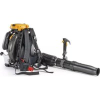
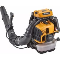
This machine is a snowplough.
The machine is equipped with a snow clearing auger, protected by a cover, which sends the snow into a discharge chute. The auger is driven by the engine, which also provides traction to the machine. The machine is operated using the controls on the dashboard. The operator can operate the machine and use the main controls, always standing at the operator's position, behind the machine.
3.1.1 Intended use
This machine is designed and built for snow clearing, removal and ejection from side-walks, gardens, driveways and other surfaces at ground level. The snowplough must be used exclusively for snow removal.
3.1.2 Improper use
Any other use that does not comply with the above, can be dangerous and cause damage to people and/or property. Examples of improper use may include, but are not limited to:
- Using the machine on surfaces above the ground level, such as building roofs, garages, porches or other structures or buildings.
- Operating the auger when there are elements different from snow (for example, soil, grass, pebbles, etc.).
- Towing or pushing loads.
- Transporting children or other passengers.
IMPORTANT Improper use of the machine will void the warranty and relieves the Manufacturer of any liability, placing all
responsibility for damage or injury, to him/herself or third parties, on the user.
3.1.3 Type of users
This machine is intended for use by consumers, i.e. non-professional operators. It is intended for "hobby-related activities".
IMPORTANT The machine must be used by one operator.
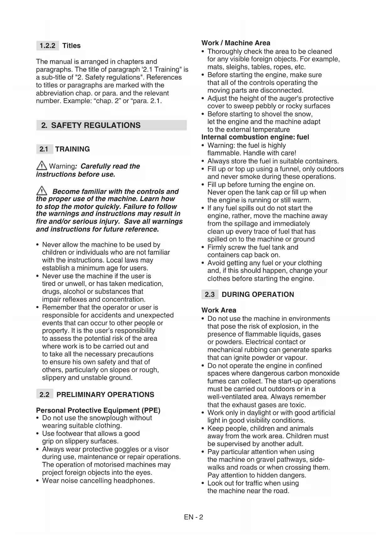
3.2 SAFETY SIGNS
The machine has various symbols on it (fig. 4). Their function is to remind the operator of the correct conduct for use, with due care and caution. Meanings of the symbols:
WARNING!

WARNING! Read the instructions before using the machine.

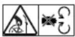
DANGER! Keep your hands and feet away from the rotating parts.

DANGER! Ejected objects. Do not direct the ejection outlet toward bystanders or animals.

DANGER! Rotating rotor. Always keep away from the snow discharge opening.

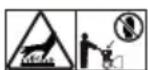
DANGER! Keep people, children and animals away from the work area.

WARNING! Remove the key and read the instructions before carrying out any maintenance or repair work.

DANGER! It is prohibited to insert the hands inside the discharge chute when the auger is moving. Switch off the engine before unclogging the discharge chute.
DANGER! Keep away from hot surfaces.
DANGER! Engines emit carbon monoxide. DO NOT start the machine in enclosed areas.
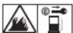
DANGER! The fuel is highly flammable and explosive. Remove the ignition key and let the engine cool down before refuelling


DANGER! Danger of fire or explosion. Do not smoke, do not use open flames or ignition sources
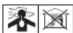
DANGER! Wear personal ear protectors.
DANGER! Wear goggles.
IMPORTANT Any damaged or illegible decals must be replaced. Order replacement decals from an Authorised Service Centre.
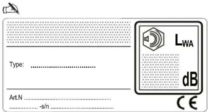
3.3 IDENTIFICATION LABEL
The identification label contains the following data (fig. 1):
- Manufacturer's address
- Type of machine
- Acoustic power level
- CE conformity marking
- Engine's operating rotation speed
- Engine power
- Engine displacement
- Month / Year of manufacture
- Serial number
- Article code
Write the identification data of the machine in the specific space on the label on the back of the cover page.
IMPORTANT Specify the identification names on the product identification label.
IMPORTANT Use the identification names whenever contacting an Authorised Service Centre
3.4 MAIN COMPONENTS
The machine is composed of the following main parts (fig. 1):
A. Chassis
B. Dashboard
C. Engine
D. Fuel tank
E. Plug for electrical starting
F. Manual starting grip
G. Deflector
H. Discharge chute
I. Paddle
J. Auger protective cover
K. Auger
L. Levelling shoes
M. Headlights (optional)
N. Wheels/Tracks
O. Auger extension (optional)
4. ASSEMBLY
For storage and transport purposes, some components of the machine are not installed in the factory and have to be assembled after unpacking. Follow the instructions below.
⚠️ Unpacking and completing the assembly should be done on a flat and stable surface, with enough space for machine handling and its packaging, always making use of suitable equipment. Do not use the machine until all the indications provided in the “ASSEMBLY” section have been carried out.
IMPORTANT The machine is supplied without engine oil or fuel.
4.1 ASSEMBLY COMPONENTS
The packaging includes the components (fig. 3) needed for assembly as listed in the table below:
| ST 526 S, ST 625, ST 665, ST 665 T, ST 726 T | ||
| Pos. | Description | Qty. |
| A | Gear lever | 1 |
| B | Screws for fixing the gear lever | - |
| C | Spacers with screws for fixing the handle | 2 |
| D | Gear lever grips and deflector guide | 2 |
| E | Funnel | 1 |
| F | Safety key | 1 |
| G | Discharge chute | 1 |
| H | Screws and self-locking nuts | 3 + 3 |
| ST 767 H | ||
| Pos. | Description | Qty. |
| A | Gear lever | 1 |
| B | Screws for fixing the gear lever | - |
| C | Spacers with screws for fixing the handle | 2 |
| D | Gear lever grip | 1 |
| E | Funnel | 1 |
| F | Safety key | 1 |
| G | Discharge chute | 1 |
| H | Screws and self-locking nuts | 3 + 3 |
| The Auger extension | 1 | |
| J | Screws for fixing the auger extension | 4 |
4.1.1 Unpacking
- Carefully open the packaging, paying attention not to lose components
- Consult the documentation in the box, including these instructions.
- Remove all the unassembled parts from the box.
- Take the snowplough out of the box.
- Dispose of the box and packaging in compliance with local regulations.
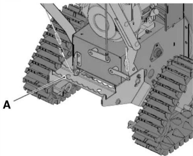
4.2 MOUNTING THE FORWARD CONTROL AND AUGER CABLES
Hook the cable loop in the specific eyelet (fig. 5.A, fig 5.B).
NOTE The cables are already fitted in the dashboard.
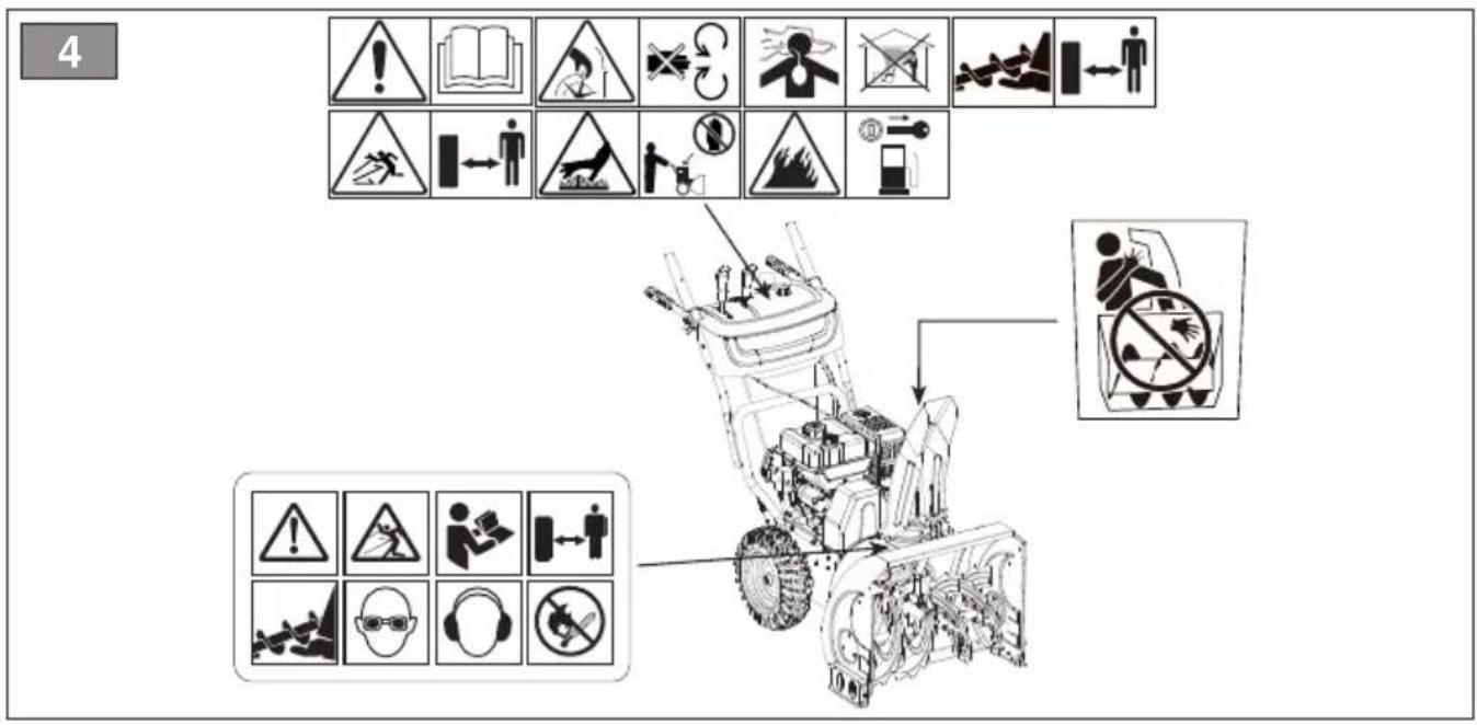
4.3 HANDLE ASSEMBLY
The handle is delivered with the dashboard already assembled. The screws for fitting the handle on the machine, the screws for fixing the gear lever, the screws for fixing the discharge chute, the gear lever and deflector lever grips are delivered in a separate packaging inside the machine's packaging. Mount as follows:
- Bring the two end tubes of the handle (fig. 6.A) close to the support (fig. 6.B).
- Insert the spacers (fig. 6.C) and align them with the holes, keeping in mind the correct diameter (smaller cavity toward outside, larger cavity toward inside).
- Insert the screws, the washers and the nuts in the holes and tighten them.
4.3.1 Lever grips assembly
Screw each grip in the threaded rods of the levers (fig. 7). Tighten the fixing nut until closed.
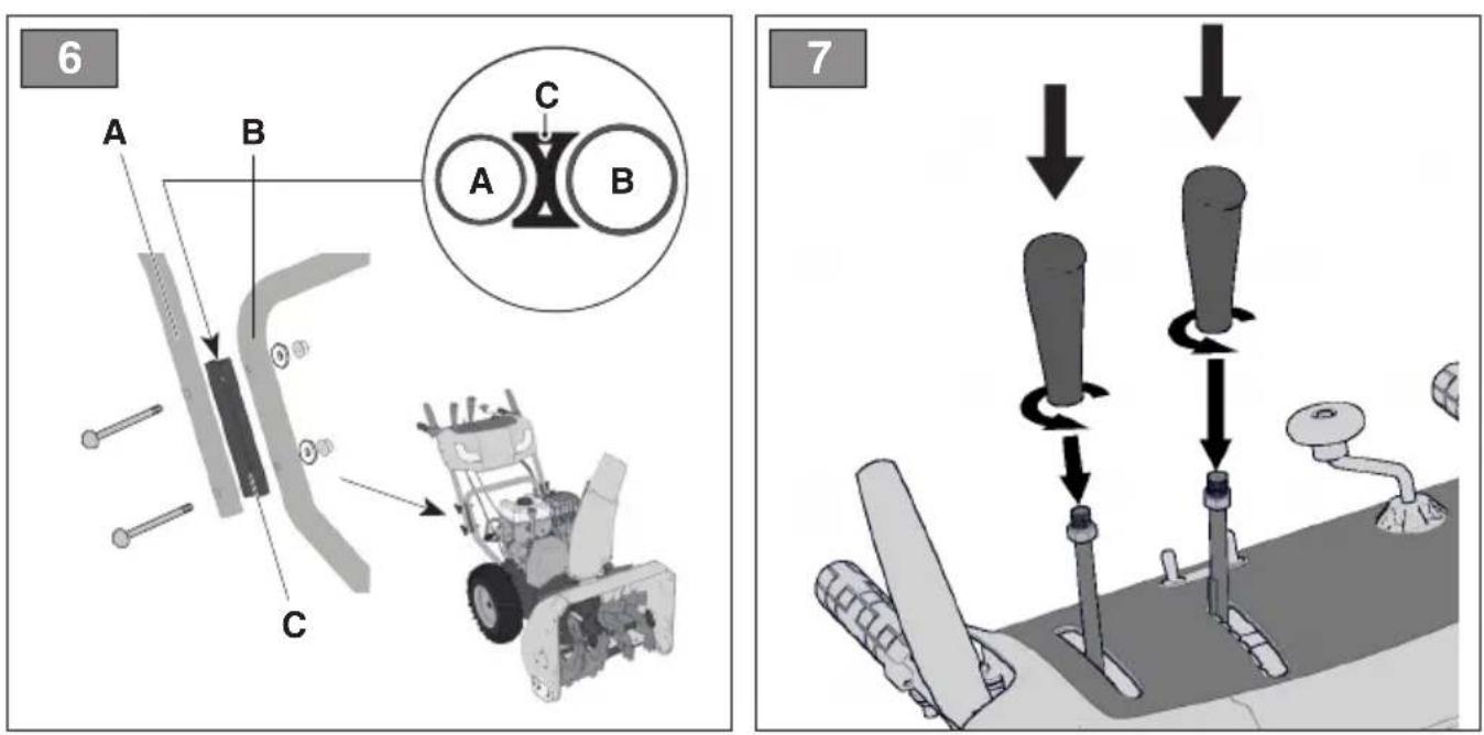
4.4 GEAR LEVER ASSEMBLY
- Insert the joint (fig. 8.A) of the gear lever in the hole of the lever (fig. 8.B) to connect it to the transmission and secure it with the nut (fig. 8.C).
- Bring the upper part (fig. 8.D) of the gear lever close to the hole of the lower part of the gear lever and secure it by inserting the pin (fig. 8.E) and the cotter pin (already assembled on the gear lever) (fig. 8.F).
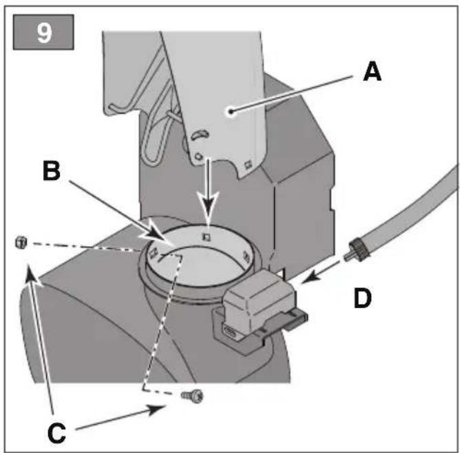
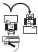
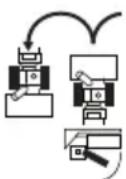
4.5 DISCHARGE CHUTE ASSEMBLY
- Put the discharge chute (fig. 9.A) on the flange coupling (fig. 9.B) making the two holes at the base of the chute coincide.
- Insert the screws and the washers in the holes and tighten (fig. 9.C).
4.5.1 Connecting the discharge chute guide cable
The purpose of the guide cable is to connect the discharge chute to the guide handle located on the dashboard, thus allowing guiding the chute in the desired direction.
- Insert the cable (fig. 9.D) and fasten the ring nut on the rotation system of the chute.
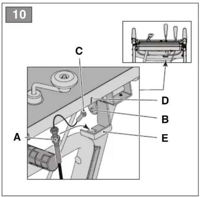
4.5.2 Mounting the deflector's guide cable (ST 526 S, ST 625, ST 665, ST 665 T, ST 726 T)
The purpose of the deflector's guide cable is to connect the chute's deflector to the control lever on the dashboard, allowing thus raising/lowering the chute to guide it in the desired direction.
- Insert the end of the guide cable (fig. 10.C) on the pin (fig. 10.B).
- Insert the cotter pin on the pin and tighten (fig. 10.D).
- Insert the adjustment screw (fig. 10.A) in its seat (fig. 10.E) and tighten the nut (fig. 10.A).
- Pass the cable on the oil plug fair-lead carefully, to avoid getting close to the muffler.
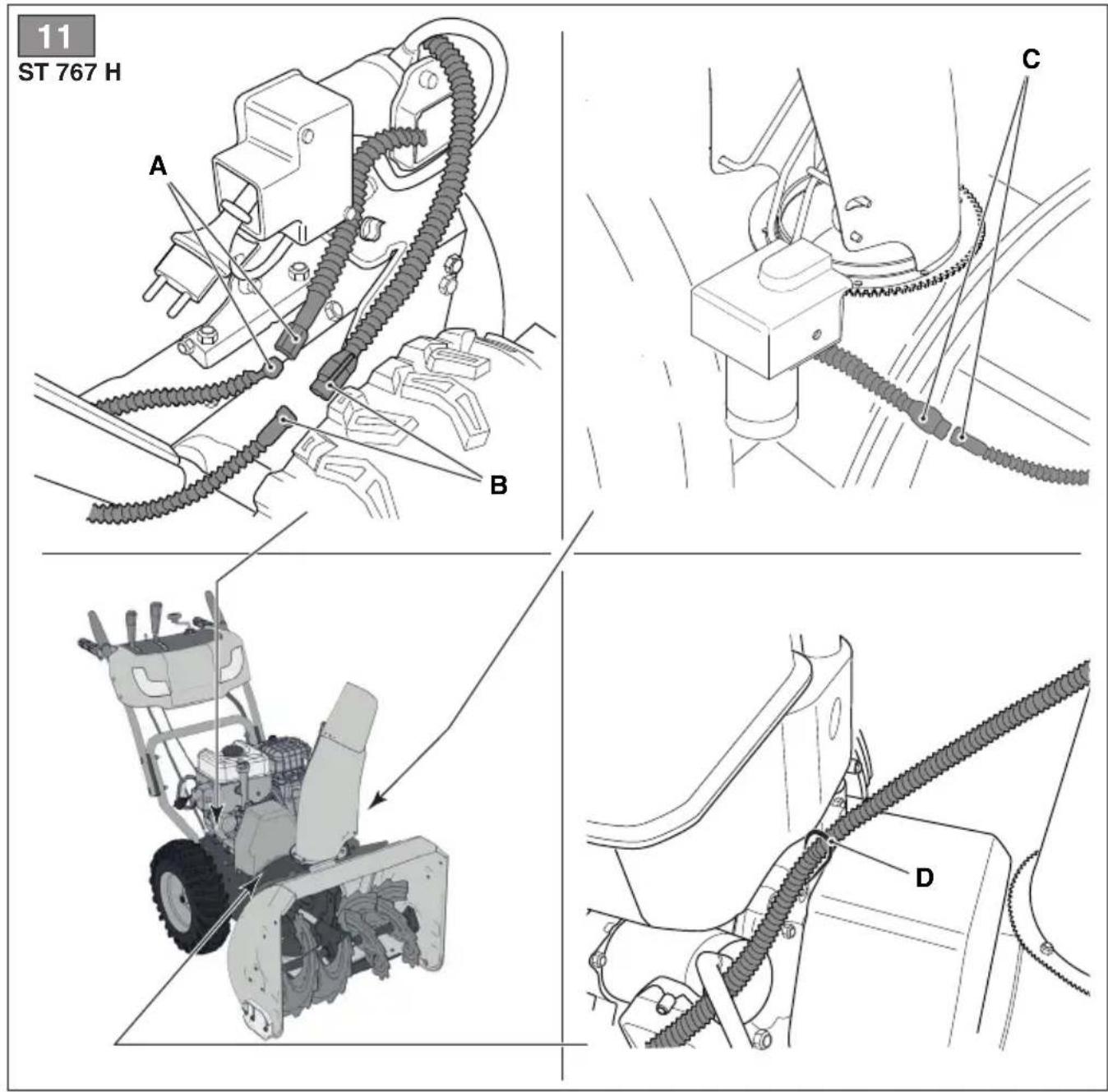
4.5.3 Fastening the guiding connectors of the deflector and of the discharge chute (ST 767 H)
By connecting the guiding electrical connectors of the deflector and of the discharge chute, power is delivered to the system, allowing thus guiding the discharge chute in the desired direction.
Fasten the connectors of the dashboard power supply (fig. 11.A), of the deflector's guiding cable (fig.11.B) and of the discharge chute (fig. 11.C) to their couplers. Pass the cable through the fair-lead (fig. 11.D) behind the engine.
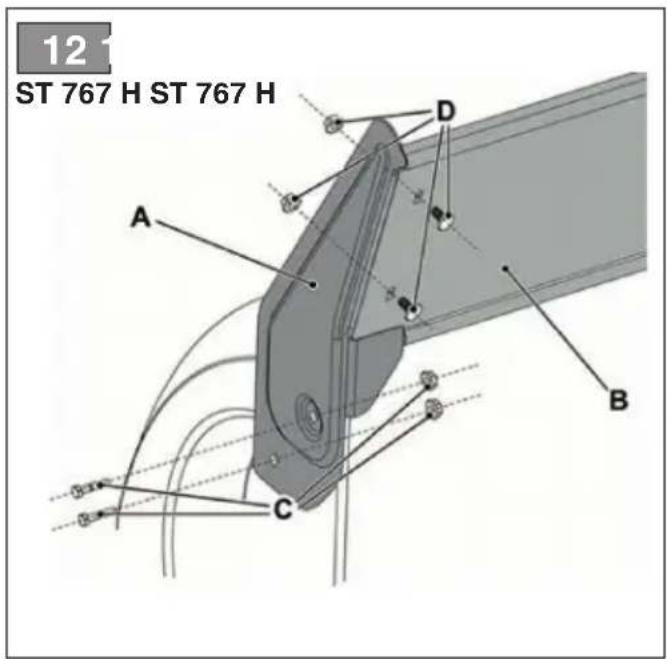
4.6 MOUNTING THE AUGER EXTENSION (ST 767 H)
The auger extension allows collecting a large quantity of snow in the auger, ensuring thus easier and faster operation.
- Place the auger extension on the upper part of the auger, as indicated in the figure (fig. 12.A).
- Insert the screws and the nuts in the holes and tighten them (fig. 12.B).
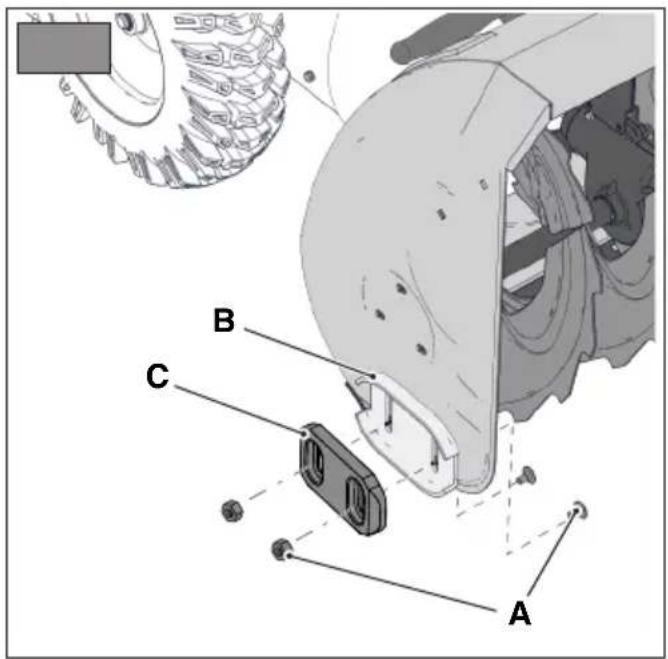
4.7 LEVELLING SHOES
The shoes are used to adjust the distance between the auger and the ground, to protect the auger.
The machine is supplied with 2 types of shoes:
- metallic shoes: to be used when operating on hard or uneven surfaces, that may damage the shoes, for example asphalt or gravel paths (fig. 16.B).
- plastic shoes: to be used when operating on softer surfaces that do not damage the shoes, such as gardens or alleys (fig.16.C).
To mount them:
- Loosen the screws (fig. 16.A).
Raise / lower the shoes (fig. 16.B, 16.C). - Fasten the screws.
Check that the shoes are adjusted at the same level on both sides.
5. CONTROLS
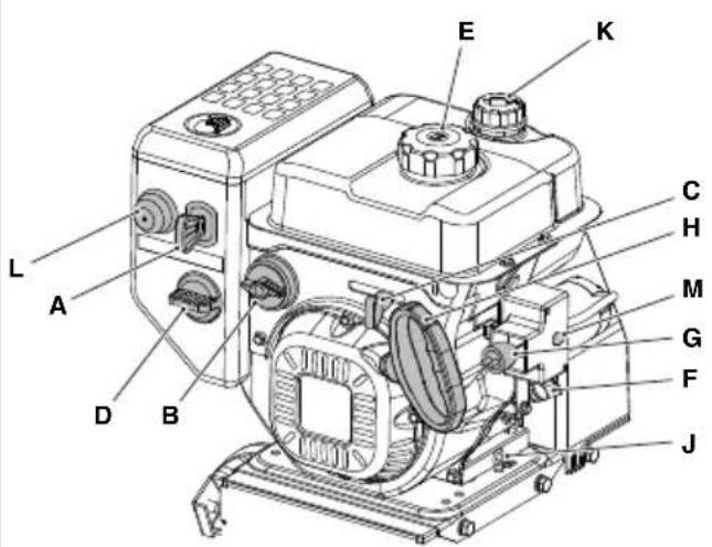
5.1 IGNITION KEY
Used to start and stop the engine. The ignition key has two positions (fig. 15.A):
- Key removed - OFF - the engine stops and cannot be started.
- Key inserted - ON - the engine can be started and operated.
IMPORTANT The engine will not start if the safety key is not completely inserted. On certain models, the key must also be turned clockwise to allow starting.
5.2 FUEL TAP
Opening the fuel tap allows the fuel supply (fig. 15.B).
- counter-clockwise - open.
- clockwise - closed.
5.3 THROTTLE COMMAND
Regulates the engine's r.p.m.
The positions indicated on the plate correspond to a (fig. 15.C):


STOP
- Full capacity. To be used always when starting the machine and during operation.
- Minimum. it is used when the engine is warm enough during stationary phases.
- Stop position (if available). The machine stops immediately.
- Intermediary position (if available). Moving the throttle lever toward the hare/turtle, the speed can be increased/reduced and the suitable speed for the work requirements can be selected (high snow, uneven ground, etc.).
5.4 CHOKE COMMAND
It is used to cold start the engine. The choke control features two positions (fig. 15.D):

The choke is engaged (for cold start).

The choke is disengaged (normal operation and warm start).
5.5 PRIMER
By pressing the primer rubber control, fuel is injected in the carburettor's intake manifold, facilitating thus the engine cold start (fig. 15.L).
5.6 MANUAL STARTING GRIP
Allows the engine to be started by hand (fig. 15.H).
5.7 ELECTRICAL START COMMAND
Allows the engine to be started electrically (fig. 15.M) when the machine is connected to the mains through the specific three-pole plug equipped with grounding (fig. 15.G).
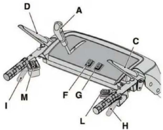
5.8 FORWARD CONTROL
Allows moving the machine forward.
- To move forward, lower the lever (fig. 14.D) until it comes into contact with the grip.
- Release the lever to stop the forward movement of the machine.
5.9 STEERING LEVER
The steering lever opens a differential locking system for an easier steering of the machine.
To turn to the right, press the lever (fig. 14.H) and simultaneously direct the machine to the right. The thrust applied on the machine determines the right wheel or track to lock, allowing thus turning to the right.
To turn to the left, press the lever (fig. 14.1) and simultaneously direct the machine to the left. The thrust applied on the machine determines the left wheel or track to lock, allowing thus turning to the left.
NOTE Turning without using the lever may be more difficult.
NOTE Turning without using the lever may cause the track to be displaced.
5.10 AUGER CONTROL
Operates the auger rotation.
- To operate the auger rotation, lower the lever (fig. 14.C) until it comes into contact with the grip.
- If the auger control is operated individually, upon its release, the auger rotation stops and the control automatically returns to the initial position.
If the auger control is operated together with the forward control, it will remain engaged upon release. It can be disengaged only by releasing the forward control as well (fig. 14.D).
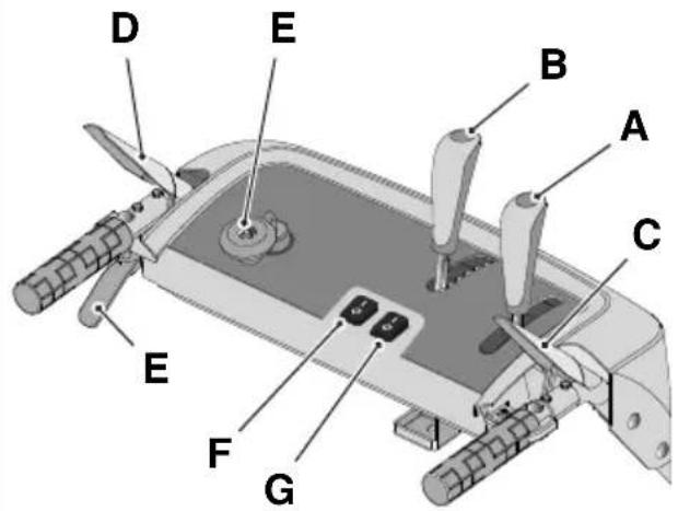
5.11 GEAR LEVER
The machine is equipped with a gearbox operated with a lever (fig. 14.A):
- 6 gears for adjusting the forward speed.
- 2 gears for adjusting the reverse speed.
5.12 CHUTE AND DEFLECTOR GUIDING (VERSION WITH HANDLE)
The discharge chute rotation is adjusted using the knob that allows guiding the snow discharge in the desired direction.
-
Turn the knob (fig. 14.E) clockwise / counter-clockwise to guide the chute.
The deflector is operated downward or upward using the specific lever (fig. 14.B). Move the lever forward/ backward to lower / raise the deflector. -
Lever completely forward = deflector lowered.
- Lever completely backward = deflector raised.
5.13 CHUTE AND DEFLECTOR ELECTRICAL GUIDING (VERSION WITH BUTTONS)
Allows guiding the snow discharge in the desired direction.
- Press the button (fig. 14.L) forward and backward to guide the deflector (fig. 1.G).
- Press the button (fig. 14.M) to the right / left to guide the discharge chute (fig. 1.H).
5.14 HEADLIGHTS AND GRIP HEATING SWITCHES (OPTIONALS)
To switch on the headlights, move the switch to position I (fig. 14.F).
• Headlights ON = switch in position I.
To switch on the handle heating, move the switch to position I (fig. 14.G).
• Heating ON = switch in position I.
5.15 LIFTING PEDAL
Pedal (fig. 16.A) for adjusting the operating height of the auger:
- Pos. 1 - completely lifted. It is used to move the machine.
- Pos. 2 - operation. The auger is moved to the intermediary position. It is used during normal operating conditions.
- Pos. 3 - in contact with the ground. The auger is completely lowered and in contact
with the ground. The front part of the tracks remains lifted from the ground. It is used in special conditions (e.g. icy snow).
To adjust the height of the auger, proceed as follows:
• Take a hold of the drive handles with both your hands.
- Press the pedal and raise / lower the machine at the same time, according to the position to be set.
- Release the pedal: the machine locks in the selected position.
6. USING THE MACHINE

The safety regulations to
follow while using the machine are described in chap. 2. Strictly comply with these instructions to avoid serious risks or hazards.
6.1 PRELIMINARY OPERATIONS
Check if there is fuel and check the oil level before using the machine. For the methods and precautions regarding refuelling and oil top up (see par. 7.2 and par. 7.3).
Before using the machine, adjust the height of the shoes to adjust the machine to the ground conditions (see par. 4.7).
6.2 SAFETY CHECKS
Familiarise yourself with the contents before proceeding. Moreover, perform the following safety checks and check that the results correspond to those outlined on the tables.

Always carry out the safetycks before use.
6.2.1 General check
| Object Result | |
| Fuel lines and connections. | No leaks. |
| Electrical cables. All insulation intact.No mechanical damage. | |
| Oil lines No leaks. | No damage. |
| Test driving No abnormal vibrations.No abnormal sound. | |
6.2.2 Traction and auger operation test
| Action Result | |
| Start the machine (section 6.3); | The wheels and the auger must remain stationary. |
| Traction operation test | |
| Press the forward control (fig. 14.D). | The wheels move the snowplough forward. |
| Release the forward control (fig. 14.D). | The wheels stop. |
| Auger operation test | |
| Press the auger control (fig. 14.C) | The auger starts rotating. |
| Release the auger control. | The auger stops |
| Wheel and auger operation test | |
| Keeping the forward control pressed (fig. 14.D), press the auger control (fig. 14.C). | The wheels move the snowplough forward and the auger starts rotating. |
| Release the auger control (fig. 14.C). | The wheels rotate and auger continues to rotate. |
| Release the forward control (fig. 14.D). | The wheels will lock and the auger stops. |

If any of the results fail to match indications provided in the tables below, it is not possible to use the machine! Take it to a service centre to be checked and repaired if necessary.
- Open the fuel tap (fig. 15.B).
- Insert the safety key and turn it clockwise where indicated (fig. 15.A).
6.3.1 Cold start
- Move the throttle control to full capacity (fig. 15.C).
- Engage the choke (fig. 15.D).
- Press the primer control (fig. 15.L) two or three times. Make sure the hole is covered by your finger when you press the command.
- Start with the electrical (par. 6.3.4) or manual control (par. 6.3.3).
- Disengage the choke (fig. 15.D).
IMPORTANT Before operating the machine, wait for a few minutes for the oil to warm up.
6.3.2 Warm start
- Move the throttle control to full capacity (fig. 15.C).
- Check that the choke is disengaged (fig. 15.D).
- Start with the electrical or manual control (see below).
IMPORTANT Do not press
the primer for warm start.
6.3.3 Manual starting
To manually start the engine, slowly pull the grip (fig. 15.H) outward, until a certain resistance is felt. At that point, pull forcefully and accompany the grip upon release.
Repeat the operation until the engine starts.
NOTE Do not try more than 3/4 times, otherwise the engine may be flooded. Check the potential causes of failure to start in the "Problems identification table".
6.3.4 Electrical starts
⚠️ Make sure that the power supply system is equipped with grounding and protection system.
- Insert the plug of the power supply cable (fig. 15.G) in a 230 V power socket.
- Press the start button to start the engine.
- Once the engine starts, remove the plug from the power supply.
6.3.5 Operation
To use the machine proceed as follows:
- Using the specific control, guide the chute and the deflector (fig. 1.G).
- To increase the length of the snow jet, guide the deflector upward.
- To decrease the length of the snow jet, guide the deflector downward.
- Set the machine running according to the pathway and snow quantity.
- Press the auger control (fig. 14.C) to activate the forward rotation of the auger.
- Press the forward control (fig. 14.D) to engage the traction.
NOTE Always use the engine at full capacity while using the machine.
6.3.6 Steering
The steering is operated in different manner, based on the snowplough model.
ST 526 S, Turning the machine in
ST 625, the desired direction.
ST 665
On models with "diff-lock release" the steering is facilitated (see the technical data table).
ST 665 T, Press the right or left hand
ST 726 T, steering levers (fig. 14.H, fig 14.I)
ST 767 H to turn to the right or to the left.
6.3.7 Gear shift
The gear shift is operated in different manner, based on the snowplough model.
ST 526 S, The gear shift must be performed
ST 625, with the machine at a standstill.
ST 665, To shift the gears, proceed as follows:
ST 665 T, • Stop the machine by releasing ST 726 T the forward control (fig. 14.D) and the auger control (fig. 14.C).
- Move the gear lever (fig. 14.A) to the desired position.
- Resume normal operation.
IMPORTANT Shifting the
gears with the machine running damages the transmission system.
ST 767 H The gears must be shifted with the machine running
To shift the gears, proceed as follows:
- During normal operation, move the gear lever to the desired position (fig. 14.A).
IMPORTANT Shifting the
gears with the machine at a standstill may be more difficult.
6.4 STOP
To stop the machine, release the auger control (fig. 14.C) and the forward control (fig. 14.D).
To switch off the machine, proceed in one of the following ways:
- Remove the safety key (fig. 15.A).
- Move the throttle control (fig. 15.C) to stop position.
The fuel tap must be closed whenever the machine is not operating.
The engine may be very warm immediately after it is shut off. Do not touch the exhaust or adjacent parts. This can cause burn injuries.
IMPORTANT If you must move away from the machine, always remove the safety key (fig. 15.A).
6.5 OPERATING SUGGESTIONS
- Snow removal is more efficient when it is still fresh. Go again through the cleared areas to remove snow residues
- If possible, eject the snow in the wind direction. Check the distance and the direction of the jet of ejected snow.
- In case of strong winds, lower the deflector so as to guide the discharged snow on the ground, reducing thus the possibility of the snow being carried away in improper areas.
- Upon finishing the work, leave the machine running for a few minutes, to avoid the formation of ice in the ejection outlet.
- Always maintain a speed adequate to the snow conditions and adjust it so that the snow is ejected at a constant flow.
- Reduce the engine rotations before stopping it.
6.6 AFTER USE
- Clean (par. 7.4).
- Move all controls forward and backward several times.
- Check that the choke is engaged.
- Make sure there are no loose or damaged components. If necessary, replace the damaged components and tighten any loose screws and bolts.
Do not cover the machine until the engine and the muffler are cold.
7. MAINTENANCE
7.1 GENERAL INFORMATION
IMPORTANT The safety regulations that must be followed during maintenance operations are described in par. 2.4.
All controls and maintenance operations must be carried out with the machine off and the engine off. Remove the key and read the applicable instructions before starting any cleaning or maintenance procedure.
⚠ Wear suitable clothing, gloves and glasses before performing any maintenance operations.
- The frequency and type of procedures are outlined in the "Maintenance table". The table will help you maintain your machine's safety and performance. It summarises the main interventions to be made and the frequency applicable to end of them. Carry out the relevant task as soon as it is scheduled to be performed.
- The use of non-original parts and accessories could have negative effects on machine operation and safety. The manufacturer declines any responsibility for damage or injury caused by said products.
• Genuine spare parts are supplied by Authorised Assistance Centres and Dealers.
IMPORTANT Any maintenance and adjustment operations not described in this manual must be carried out by your dealer or Authorised Service Centre.
7.2 REFUELLING
To refuel:
- Unscrew the tank closing cap (fig.15.E) and remove it.
- Insert the funnel (fig. 15.1).
- Refuel and take the funnel off (fig.15.1).
- At the end of refuelling, screw the fuel plug back on (fig.15.E) and clean any spillage.
NOTE Do not fill the fuel tank until the rim.
NOTE Only use the fuel specified in the technical data table. Do not use other types of fuel. Ecological fuels may be used, such as alkylate based petrol. The composition of this petrol has a lower impact on people and on the environment. No negative effects have been reported in connection to their use. Nonetheless, there are types of alkylate petrol on the market for which it is not possible to provide specific indications on their use. For further information, refer to the instructions and data provided by the manufacturer of the alkylate based petrol.
NOTE Fuel is perishable and should not remain in the tank for more than 30 days. Before storing for long periods, fill
the tank with a fuel quantity sufficient for finishing the last use (cap. 8).
7.3 CHECK/TOP-UP ENGINE OIL

Always check the oil level before use.
NOTE The machine is delivered to the user without engine oil.
7.3.1 Check/top-up
Procedure:
- Make sure that the machine is level before performing the check.
- Clean around the plug (fig. 15.F). Unscrew and remove it. Clean the rod.
- Insert the rod completely, without screwing it in position.
- Remove the rod again. Check the oil level.
- Unscrew the oil filler plug (fig. 15.K).
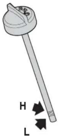
- If the level is low, top up to the "L" mark (fig. 17).
- For the correct replacement procedure, see par. 7.3.2

Do not overfill as this could use the engine to overheat. If the level exceeds the "H" mark, drain of the correct level is achieved.
NOTE For the oil type to be used, see the "Technical data table".
7.3.2 Replacement

The oil may be very hot if removed after the engine has been switched. Consequently allow the engine to down for a few minutes before needing to drain off the oil.
Replace the engine oil at the intervals indicated in the "Maintenance table". Replace the oil more often if the engine must operate in difficult conditions. Proceed as follows:
- Place the machine on a flat surface.
- Place a collection container next to the discharge pipe.
- Remove the filler plug (fig. 15.K).
- Remove the discharge plug (fig. 15.J).
- Collect the oil in a suitable vessel.
- Screw the oil discharge plug.
-
Clean up any spills.
-
Fill with new oil. For the required oil quantity, see the "Technical data table".
- Upon each refuelling, start the engine and let it run for at least 30 seconds.
- Check that there are no oil leakages.
- Stop the engine. Wait for 30 seconds and check the oil level again. If necessary, also see "check/top up" (par. 7.3.1).
IMPORTANT Hand the spent
oil over to a disposal facility in accordance with local provisions.
7.4 CLEANING

Perform the cleaning operations with machine switched off. Do not attempt remove the snow from the discharge before having first performed the following
- Release the auger control.
- Switch off the engine.
- Remove the ignition key.
Always clean the machine after use. Observe the following instructions for cleaning:
- Use the paddle (fig. 1.1) to clean the discharge chute and the machine from snow residues.
- Clean the engine with a brush and/or compressed air.
- Do no spray water directly on the engine.
- After cleaning with water, start the machine and the auger to remove the water that may otherwise infiltrate in the bearings and cause damages.
IMPORTANT Never use pressurised water. It may damage the electrical components.
7.5 SPARK PLUG
For operations to be performed on the spark plug, refer to a Dealer or an Authorised Service Centre. Refer to the maintenance table and problem identification table for interventions concerning the spark plug.
7.6 CARBURETTOR
The carburettor is pre-adjusted by the manufacturer. Refer to the problem identification table to check when interventions are required on the carburettor (cap. 12).
7.7 NUTS AND BOLTS
- Keep all nuts, bolts and screws tight to be sure the equipment is in safe working condition.
- Regularly check that the fixing nuts of the discharge chute are correctly tightened.
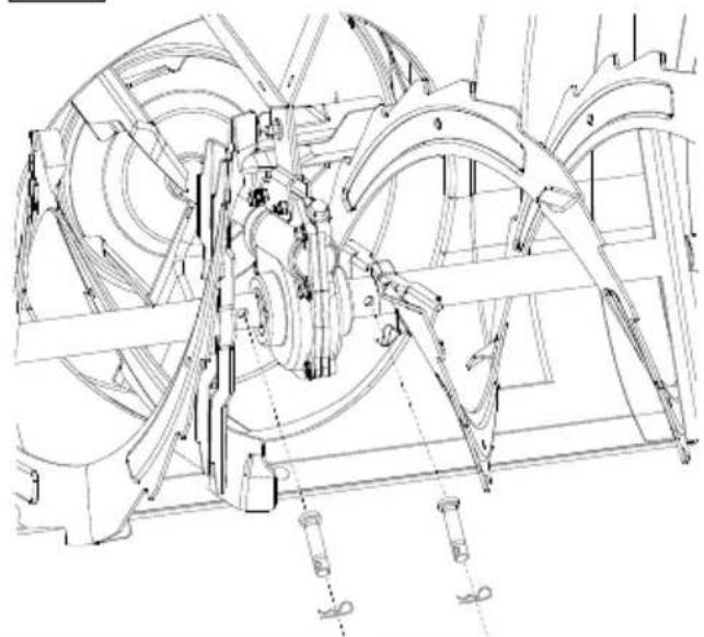
7.8 AUGER SHAFT
To facilitate the rotation of the auger, it is recommended to regularly grease the holes on the auger shaft using a syringe greaser.
To grease:
- Remove cotter pins and screws (fig. 18).
- Grease the holes and rotate the auger on the shaft a few times to allow the grease to flow inside the shaft.
– Reposition the screws and cotter pins (fig. 18).
8. STORAGE
When you intend to put your machine away for more than 30 days:
- Drain the fuel supply circuit:
- Close the fuel tap (fig. 15.B). - Start the engine of the machine and leave it running until it stops when the fuel runs out.
-
Replace the engine oil if this operation has not been performed during the last three months.
-
Thoroughly clean the snowplough.
-
Check the snowplough for any damage. If necessary, repair it.
-
If the paint is damaged, restore it to prevent rust formation.
-
Protect the metallic surfaces exposed to rust formation.
-
Store the snowplough in a closed room, if possible.
9. ASSISTANCE AND REPAIRS
This manual provides all the necessary information to run the machine and for correct basic maintenance operations which can be performed by the user. Any regulations and maintenance operations not described herein must be carried out by your Dealer or Authorised Service Centre, which have
the necessary knowledge and equipment to ensure that the work is carried out correctly, maintaining the correct degree of safety and the original operating conditions of the machine. Any operations performed in unauthorised centres or by unqualified persons will totally invalidate the Warranty and all obligations and responsibilities of the Manufacturer.
- Only Authorised Service Centres can carry out guaranteed repairs and maintenance.
- The Authorised Service Centres only use genuine spare parts. Genuine spare parts and attachments have been designed specifically for machines.
- Non-genuine spare parts and accessories are not approved. Use of non-genuine spare parts and accessories cause the warranty to be voided.
- It is advisable to send your machine once a year to an Authorised Service Centre for servicing, assistance and safety device inspection.
10. WARRANTY COVERAGE
The warranty covers all material and manufacturing defects. The user must follow all the instructions provided in the accompanying documentation.
The warranty does not cover damage caused by:
- Failure to become familiar with the documentation accompanying the machine.
- Carelessness.
- Incorrect or prohibited use or assembly.
- Use of non-genuine spare parts.
- Use of attachments not supplied or not approved by the manufacturer.
The warranty does not cover:
- Normal wear and tear of consumables, such as drive belts, augers, headlights, wheels, safety bolts and wires.
• Normal wear and tear.
• Engines. Engines are covered by the warranty provided by the relative manufacturer in compliance with the specified terms and conditions.
The purchaser is protected by his or her own national legislation. The purchaser's rights under the national laws or his or her own country are not in any way restricted by this warranty.
11. MAINTENANCE TABLE
| Intervention Frequency Paragraph | |||
| First time | Subsequently every | ||
| MACHINE | |||
| Check all fasteners | - Before | each use 7.7 | |
| Safety checks/check controls | - Before | each use 6.2 | |
| General cleaning and inspection | - After each use 7.4 | ||
| Clean the discharge area | - 5 hours / after every use 7.4 | ||
| Lubricate the drive shaft | - 25 hours / after every season *** | ||
| Lubricate the auger shaft | - 10 hours / after every season 7.8 | ||
| ENGINE | |||
| Cleaning the spark plug | - | 25 hours / after every season | *** |
| Spark plug replacement | - 100 hours / after every season | *** | |
| Check / Top up engine oil level | - | 5 hours / after every use | 7.3.1 |
| Replacement of the engine oil | 5 hours | 50 hours / after every season | 7.3.2 |
*** Interventions that must be carried out by your Dealer or by an Authorised Service Centre
12. TROUBLESHOOTING
| PROBLEM PROBABLE CAUSE SOLUTION | ||
| 1. Failure to start | Ignition key not inserted. Insert the ignition key | |
| No fuel Fill the tank with clean and pure fuel. | ||
| Disengaged choke Engage the choke. | ||
| Primer not pressed Press the primer | ||
| Engine flooded Wait a few minutes before starting. Do not press the primer and disengage the choke. | ||
| Disconnected spark plug wire Contact your Authorised Service Centre. | ||
| Spark plug damaged Contact your Authorised Service Centre. | ||
| Old fuel Contact your Authorised Service Centre. | ||
| Water in the fuel Contact your Authorised Service Centre. | ||
| 2. Power loss. | Too much snow ejected Reduce the speed | |
| Fuel tank plug covered with ice or snow. | Remove the ice or snow on top or around the tank plug. | |
| Silencer dirty or clogged | Contact your Authorised Service Centre. | |
| 3. The engine runs at minimum or operates irregularly | The choke is engaged | Disengage the choke. |
| Old fuel Contact your Authorised Service Centre. | ||
| Water in the fuel Contact your Authorised Service Centre. | ||
| The carburettor must be replaced | Contact your Authorised Service Centre | |
| 4. Excessive vibrations | Loose parts or auger or rotor damaged. | Tighten all fixing devices.Replace the damaged parts at an Authorised Service Centre. |
| Handle positioned incorrectly. Make sure that the handle is fastened in its position. | ||
| 5. Losses or slowing down during snow ejection | Clogged discharge chute. | Clean the discharge chute. |
| Jammed auger. | Remove any residues or foreign objects from the auger. | |
| 6. The traction is inoperative | The traction operation control cable is adjusted incorrectly. | Contact your Authorised Service Centre. |
If problems persist after implementing the solution, contact your Dealer.
ÍNDICE
7.8 EJE DE LA CÓCLEA
1.1 KUIDAS KASUTUSJUHENDIT LUGEDA
11.HUOLTOTAULUKKO 14
- VIKOJEN PAIKANNUS 14
1. YLEISTÄ
1.1 KÄYTTÖOPPAAN LUKEMINEN
5.4 Commande choke....8
5.5 Amorceur 8
5.4 Commando choke....8
5.5 Primer 8
2.5 BESCHERMING VAN DE OMGEVING
5.14 SCHAKELAARS KOPLAMPEN EN VERWARMING HANDVAT (OPTIE)
7.7 MOEREN EN SCHROEVEN VOOR BEVESTIGING
- BLI KJENT MED MASKINEN 4
5.4 Choke-innstilling....7
5.5 Primer 7
2.4 VEDLIKEHOLD, OPPBEVARING OG TRANSPORT
3. BLI KJENT MED MASKINEN
3.1 BESKRIVELSE AV MASKINEN OG TILSIKTET BRUK
4.7 UTJEVNINGSSKINNER
5.8 FREMDRIFTSINNSTILLING
5.2 Kurek paliwa....8
10.ZAKRES GWARANCJI 14
-
TABELA CZYNNOŚCI KONSERWACYJNYCH 15
-
IDENTYFIKACJA USTEREK 16
1. INFORMACJE OGÓLNE
1.1 JAK POSŁUGIWAĆ SIĘ INSTRUKCJĄ OBSŁUGI
6.1 CZYNNOŚCI WSTĘPNE
5.6 MÂNER PENTRU PORNIREA MANUALÃ
INNEHÅLLSFÖRTECKNING
-
ALLMÄN INFORMATION ...... 1
-
SÄKERHETSFÖRESKRIFTER 2
-
FÖRVARING....12
-
SERVICE OCH REPARATIONER......12
-
GARANTITÄCKNING 13
11.UNDERHÅLLSTABELL 13
- FELSÖKNING.... 14
1. ALLMÄN INFORMATION
1.1 HUR DU LÄSER HANDBOKEN
5.6 HANDTAG FÖR MANUELL START
UK DECLARATION OF CONFORMITY
(Supply of Machinery (Safety) Regulations 2008, S.I. 2008 No. 1597, Annex II, part A)
- The company: ST. S.p.A. – Via del Lavoro, 6 – 31033 Castelfranco Veneto (TV) – Italy
- Hereby declares under its own responsibility that the machine (function):
: Pedestrian controlled Snow thrower (shovelling-removing snow)
a) Homologation type: ST 526 S
c) Serial number: 23A••STH000001 ÷ 99L••STH999999
d) Engine: a scoppio
3. Conforms to UK Regulations:
• S.I. 2008/1597 - Supply of Machinery (Safety) Regulations 2008
• S.I. 2016/1091 - Electromagnetic Compatibility Regulations 2016
- S.I. 2012/3032 - The Restriction of the Use of Certain Hazardous Substances in Electrical and Electronic Equipment Regulations 2012
• S.I. 2001/1701 - Schedule 8 - Noise Emission in the Environment by Equipment for use Outdoors Regulations 2021
4. Reference to harmonised standards:
ISO 8437:1989+A1:1997
EN 55012:2007+A1
EN 61000-6-1:2007
EN IEC 63000:2018
g) Measured sound power level: 104 dB(A)
h) Guaranteed sound power level: 107 dB(A)
i) Net power installed: 5 kW
n) Person authorised to compile the technical file: ST. S.p.A.
o) Castelfranco Veneto, 01/04/2023 CEO Stiga Group
Sean Robinson

UK Importer:
STIGA LTD
Unit 8, Bluewater Estate Plympton,
Devon, PL7 4JH, England

CE
UK DECLARATION OF CONFORMITY
(Supply of Machinery (Safety) Regulations 2008, S.I. 2008 No. 1597, Annex II, part A)
- The company: ST. S.p.A. – Via del Lavoro, 6 – 31033 Castelfranco Veneto (TV) – Italy
- Hereby declares under its own responsibility that the machine (function):
: Pedestrian controlled Snow thrower (shovelling-removing snow)
a) Homologation type: ST 625, ST 665, ST 665 T, ST 726 T, ST 767 H
c) Serial number: 23A••STH000001 ÷ 99L••STH999999
d) Engine: a scoppio
- Conforms to UK Regulations:
• S.I. 2008/1597 - Supply of Machinery (Safety) Regulations 2008
• S.I. 2016/1091 - Electromagnetic Compatibility Regulations 2016
- S.I. 2012/3032 - The Restriction of the Use of Certain Hazardous Substances in Electrical and Electronic Equipment Regulations 2012
• S.I. 2001/1701 - Schedule 8 - Noise Emission in the Environment by Equipment for use Outdoors Regulations 2021
- Reference to harmonised standards:
EN ISO 12100:2010
ISO 8437-1:2019
ISO 8437-2:2019
ISO 8437-4:2019
EN ISO 14982:2009
EN IEC 63000:2018
| ST 625 | ST 665, ST 665T | ST 726 T | ST 767 H | ||
| g) Measured sound power level: | 99 | 100 103,6 | 103 | dB(A) | |
| h) Guaranteed sound power level: | 102 | 103 107 | 106 | dB(A) | |
| i) Net power installed: | 5,2 6,2 | 7,8 9,0 | kW |
n) Person authorised to compile the technical file:
ST. S.p.A.
Via del Lavoro, 6
31033 Castelfranco Veneto (TV) - Italia
o) Castelfranco Veneto, 01/04/2023
CEO Stiga Group
Sean Robinson

UK Importer: STIGA LTD
Unit 8, Bluewater Estate Plympton,
Devon, PL7 4JH, England

| FR (Traduction de la notice originale)Déclaration CE de Conformité(Directive Machines 2006/42/CE, Annexe II, partie A)1. La Société2. Déclare sous sa propre responsabilité que la machine : Chasse-neige à conducteur à pied (raclage-déblayage neige)a) Type / Modèle de Basec) Séried) Moteur essence3. Est conforme aux prescriptions des directives :4. Renvoi aux Normes harmoniséesg) Niveau de puissance sonore mesuréh) Niveau de puissance sonore garanti i) Puissance nette installéen) Personne habilitée à établir le Dossier Technique :o) Lieu et Date | EN (Translation of the original instruction)EC Declaration of Conformity(Machine Directive 2006/42/EC, Annex II, part A)1. The Company2. Herby declares under its own responsibility that the machine:Pedestrian controlled Snow thrower(shovelling-removing snow)a) Type / Base Modelc) Serial numberd) Engine: petrol3. Conforms to directive specifications:4. Reference to harmonised Standardsg) Sound power level measuredh) Sound power level guaranteedi) Net power installedn) Person authorised to create the technical Folder:o) Place and Date | DE (Übersetzung der Originalbetriebsanleitung)EG-Konformitätserklärung(Maschinenrichtlinie 2006/42/EG, Anhang II, Teil A)1. Die Gesellschaft2. Erklärt auf eigene Verantwortung, dass die Maschine: Handgeführter Schneeräumer(schneeschaufeln-räumung)a) Typ / Basismodellc) Seriennummerd) Verbrennungsmotor3. Den Anforderungen der folgenden Richtlinien entspricht:4. Bezugnahme auf die harmonisierten Normeng) Gemessener Schallleistungspegelh) Garantierter Schallleistungspegeli) Installierte Nettoleistungn) Zur Verfassung der technischen Unterlagen befugte Person:o) Ort und Datum |
| NL (Vertaling van de oorspronkelijke gebruiksaanwijzing)EG-verklaring van overeenstemming(Richtlijn Machines 2006/42/CE, Bijlage II, deel A)1. Het bedrijf2. Verklaart onder zijn eigen verantwoordelijkheid dat de machine:Lopend bediendo sneeuwruimer (sneeuw schuiven-ruimen)a) Type / Basismodelc) Serienummerd) benzinemotor3. Voldoet aan de specificaties van de richtlijnen:4. Verwijzing naar de Geharmoniseerde normeng) Gemeten niveau van geluidsvermogenh) Gegarandeerd niveau van geluidsvermogeni) Netto geïnstalleerd vermogenn) Bevoegd persoon voor het opstellen van het Technisch Dossiero) Plaats en Datum | ES (Traducción del Manual Original)Declaración de Conformidad CE(Directiva Máquinas 2006/42/CE, Anexo II, parte A)1. La Empresa2. Declara bajo su propia responsabilidad que la máquina: Quitanieves conducido de pie (espalado/despeje nieve)a) Tipo / Modelo Basec) Matrículad) motor de explosión3. Cumple con las especificaciones de las directivas:4. Referencia a las Normas armonizadasg) Nivel de potencia sonora medidoh) Nivel de potencia sonora garantizadoi) Potencia neta instaladan) Persona autorizada a realizar el Manual Técnico:o) Lugar y Fecha | PT ( Traducción do manual original)Declaração CE de Conformidade(Diretiva de Máquinas 2006/42/CE, Anexo II, parte A)1. A Empresa2. Declara sob a própria responsabilidade que a máquina: Soprador de neve para operador apeado (remoção com pâ-remoçãoda neve)a) Tipo / Modelo Basec) Matrículad) motor a explosão3. É conforme às especificações das diretivas:4. Referência às Normas harmonizadasg) Nivel medido de potência sonorah) Nivel garantido de potência sonorai) Potência líquida instaladan) Pessoa autorizada a elaborar o Caderno Técnicoo) Local e Data |
| EL (Μετάφραση του πρωτοτύπου των οδηγιών χρήσης)ΕΚ-Δήλωση συμμόρφωσης(Οδηγία Μηχανών 2006/42/CE, Παράρτημα II, μέρος A)1. Η Εταιρία2. Δηλώνει υπεύθυνα ότι η μηχανή:Εκχιονιστήρας πεζού χειριστή(Φτυάρισμα-αποβολή χιονιού)a) Τύπος / Βασικό Μοντέλοc) Αριθμός μητρώουd) κινητήρας εσωτερικής ανάφλεξης3. Συμμορφώνεται με τις προδιαγραφές της οδηγίας:4. Αναφορά στους Κανονισμούς εναρμόνισηςg) Στάθμη μέτρησης ακουστικής ισχύοςh) Σταθμη εγγυημένης ακουστικής ισχύοςi) Καναρή εγκαταστημένη ισχύςn) Εξουσιοδοτημένο άτομο για την κατάρτιση του Τεχνικού Φυλλαδίου:o) Τόπος και Χρόνος | TR (Orijinal Talimatların Tercümesi)AT Uygunluk Beyanı(2006/42/CE Makine Direktifi, Ek II, bölüm A)1. Şirket2. Şahsi sorumluluğu altında aşağıdaki makinenin: Ayak kumandalı kar temizlememakinesi (kar küreme-giderme)a) Tip / Standart modelc) Sicil numarasıd) patlamali motor3. Aşağıdaki direktiflerin özelliklerine uygun olduğunu beyan etmektedir:4. Harmonize standartlara atifg) Ölçülen ses güç seviyesih) Garanti edilen ses güç seviyesi i) Kurulu net güçn) Teknik Dosyayı oluşturmaya yetkili kişi:o) Yer ve Tarih | MK (Превод на оригиналните упатства)Декларација за усогласеност со ЕУ(Директива за машини 2006/42/CE, АнексII, дел A)1. Компанијата2. изјавува со целосна лична одговорностдека следната машина: Расчистувач наснег (Чистење-расчиствување снег)a) Тип / основен моделс) етикетад) мотор: мотор со согорување3. Усогласено со спецификациите спореддирективите:4. Референци за усогласени нормативиг) Акустички притисокh) измерено ниво на звучна моёкностi) Ниво на гарантирана звучна моёкностn) овластено лице за составување наТехничката брошурао) место и датум |
| NO (Oversettelse av original bruksanvisning)EF- Samsvarserklæring (Maskindirektiv 2006/42/EF, Vedlegg II, del A)1. Firmaet2. Erklærer på eget ansvar at maskinen: Håndført snøslynge (Måking-rydding av sno )a) Type / Modellc) Serienummerd) Forbrenningsmotor3. Oppfyller kravene i direktivene:4. Henvisning til harmoniserte standarderg) Målt lydeffektnivåh) Garantert lydeffektnivåi) Installert nettoeffektn) Person som har fullmakt til å utferdigte teknisk dokumentasjon:o) Sted og dato | SV (Översättning av bruksanvisning i original)EG-försäkran om överensstämmelse (Maskindirektiv 2006/42//EG, bilaga II, de la)1. Företaget2. Försäkrar på eget ansvar att maskinen: Förarledd snøslunga (snöplogning/röjning)a) Typ / Basmodellc) Serienummerd) förbränningsmotor3. Överensstämmer med föreskrifterna i direktivet4. Referens till harmoniserade standarderg) Uppmätt ljudeffektnivåh) Garanterad ljudeffektnivåi) Installerad nettoeffektn) Auktoriserad person för upprättandet av den tekniska dokumentationen:o) Ort och datum | DA (Oversættelse af den originale brugsanvisning)EF-overensstemmelseserklæring (Maskindirektiv 2006/42/EF, bilag II, del A)1. Firmaet2. Erklærer på eget ansvar, at maskinen: Sneslynge betjent af gående personer (plejning/rydning af sne)a) Type / Modelc) Serienummerd) forbrændingsmotor3. Er i overensstemmelse med specifikationerne ifølge direktiverne:4. Henvisning til harmoniserede standarderg) Målt lydeffektniveauh) Garanteret lydeffektniveaui) Installeret nettoeffektn) Person, der har bemyndigelse til at udarbejde det tekniske dossier:o) Sted og dato |
| FI (Alkuperäisten ohjeiden käännös)EY-VAATIMUSTENMUKAISUUSVAKUUTUS (Konedirektivi 2006/42/EY, Liite II, osa A)1. Yritys2. Vakuuttaa omalla vastuullaan, että kone: Kävellen ohjattava lumilinko (lumenluonti/poisto)a) Typpi / Perusmallic) Sarjanumero d) räjähdysmoottori3. On yhdenmukainen seuraavien direktiivien asettamien vaatimusten kanssa:4. Viittaus harmonisoituihin standardeihing) Mitattu äänitehotasoh) Taattu äänitehotasoi) Asennettu nettoteho Ilmastointikone-Niittokone / maan ilmaus/haraus n) Teknisten asiakirjojen laatimiseenvaltuutettu henkilö:o) Paikka ja päivämäärä | CS (Překlad původního návodu k používání)ES – Prohlášení o shodě (Směrnice o Strojních zařízeních 2006/42/ES, Přiloha II, část A)1. Společnost2. Prohlášuje na vlastní odpovědnost, že stroj: Ručně vedená sněhová fréza (odhrnování / úklid sněhu)a) Typ / Základní modelc) Výrobní číslod) spalovaci motor3. Je ve shodě s nařízeními směrmic:4. Odkazy na Harmonizované normyg) Naměřená úroveň akustického výkonuh) Zaručená úroveň akustického výkonui) Čistý instalovaný výkonn) Osoba autorizovaná pro vytvoření Technického spisu:o) Misto a Datum | PL (Tłumaczenie instrukcji oryginalnej)Deklaracja zgodności WE (Dyrekywa maszynowa 2006/42/WE, Załącznik II, część A)1. Spółka2. Oświadczenie na własną odpowiedzialność, że maszyna: Odśnieżarka prowadzona przez operatora pieszego (odśnieżać łopatą)a) Typ / Model podstawowyc) Numer seryjnyd) silnik o zapłonie iskrowym3. Spełnia podstawowe wymogi następujących Dyrektyw:4. Odniesienie do Norm zharmonizowanychg) Zmierzony poziom mocy akustycznejh) Gwarantowany poziom mocy akustyczneji) Moc zainstalowana netton) Osoba upoważniona do zredagowania Dokumentacji technicznej:o) Miejscowość i data |
| HU (Eredeti használati utasítás fordítása)EK-megfelelőségi nyilatkozata (2006/42/EK gépirányelv, II. melléklet "A" rész)1. Alulirott Vállalat2. Felelősségének teljes tudatában kijelenti, hogy az alábbi gép: Gyalogvezetésű hómaró (hómarás/hóeltakarítás)a) Típus / Alaptípusc) Gyártási számd) robbanómotor3. Megfelel az alábbi irányelvekelőírásainak:4. Hivatkozás a harmonizált szabványokrag) Mért zajteljesítmény szinth) Garantált zajteljesítmény szinti) Nettó beépített teljesítményn) Müszaki Dosszié szerkesztésérefelhatalmazott személy:o) Helye és ideje | RU (Перевод оригинальных инструкций)Декларация соответствия нормам EC (Директива о машинном оборудовании 2006/42/ES, Приложение II, часть A)1. Предприятие2. Заявляет под собственную ответственность, что машина: : Снегоочиститель с пешеходным управлением (уборка/ удаление снега)a) Тип / Базовая модельc) Паспортd) двигатель внутреннего сгорания3. Соответствует требованиям следующих директив:4. Ссылки на гармонизированные нормыg) Измеренный уровень звуковой мощностиh) Гарантируемый уровень звуковой мощностиi) Чистая установленная мощностьп) Лицо, уполномоченное на подготовку технической документации:o) Место и дата | HR (Prijevod originalnih uputa)EK Izjava o sukladnosti (Direktiva 2006/42/EZ o strojevima, dodatak II, dio A)1. Tvrtka:2. pod vlastitom odgovornošću izjavljuje da je stroj: Ručno upravljana ralica za snijeg (čišćenje/raščišćavanje snijega)a) Vrsta / Osnovni modelc) Matični brojd) motor s unutarnjim izgaranjem3. sukladan s temeljnim zahtjevima direktiva:4. Primijenjene su slijedeće harmonizirane norme:g) Izmjerena razina zvučne snageh) Zajamčena razina zvučne snagei) Neto instalirana snagan) Osoba ovlaštena za pravljenje Tehničke datoteke:o) Mjesto i datum |
| SL (Prevod izvirnih navodil)ES izjava o skladnosti(Direktiva 2006/42/ES), priloga II, del A)1. Družba2. pod lastno odgovornostjo izjavlja, da je stroj: Snežni plug za stoječega delavca(kidanje/odstranjevanje snega)a) Tip / osnovni modelc) Serijska številkad) motor z notranjim izgorevanjem3. Skladen je z določili direktiv :4. Sklicevanje na usklajene predpiseg) Izmerjen nivo zvočne močih) Zagotovljen nivo zvočne moči) Neto instalirana močn) Oseba, pooblaščena za sestavo tehnične knjižice:o) Kraj in datum | BS (Prijevod originalnih uputa)EZ izjava o sukladnosti(Direktiva o mašinama 2006/42/EZ, Prilog II, deo A)1. Firma2. Daje izjavu pod vlastitom odgovornošćuda je mašina: Čistač snijega na guranje(zgrtanje/čišćenje snijega)a) Tip / Osnovni modelc) Serijski brojd) motor s unutrašnjim izgaranjem3. sukladna s osnovnim zahtjevima direktive:4. Pozivanje na uskladene normeg) Izmjereni nivo zvučne snageh) Garantovani nivo zvučne snagei) Neto instalisana snagan) Osoba ovlaštena za izradu tehničke brošure:o) Mjesto i datum | SK (Preklad pôvodného návodu na použitie)ES vyhlásenie o zhode(Smernica o Strojných zariadeniach 2006/42/ES, Priloha II, čast' A)1. Spoločnost'2. Vyhlasuje na vlastnú zodpovednosť, že stroj: Ručne vedená snehová fréza(odhrňanie / odpratávanie snehu)a) Typ / Základný modelc) Výrobné číslod) spaľovací motor3. Je v zhode s nariadeniami smerníc:4. Odkaz na Harmonizované normyg) Nameraná úroveň akustického výkonuh) Zaručená úroveň akustického výkonui) Čistý inštalovaný výkonn) Osoba autorizovaná na vytvorenie Technického spisu:o) Miesto a Dátum |
| RO ( Traducerea manualului fabricantului)CE -Declaratie de Conformitate(Directiva Mașini 2006/42/CE, Anexa II, partea A)1. Societatea2. Declară pe propria răspundere că mašina: Plug de zâpadă cu conducător pedestru(înlăturarea zăpezii cu lopata/îndepărtarea zăpezii)a) Tip / Model de bazăc) Număr de seried) motor cu combustie3. Este înconformitate cu specifica’jledirectivelor:4. Referință la Standardele armonizateg) Nivel de putere sonoră măsurath) Nivel de putere sonoră garantati) Putere netă instalatăn) Persoană autorizată să întocmeascăDosarul Tehnico) Locul și Data | LT (Originalių instrukciju vertimas)EB atitikties deklaracija(Mašinų direktyva 2006/42/CE, Priedas II, dalis A)1. Bendrovė2. Prisilma atsakomybę, kad jrenginys:Pėsčio operatoriaus valdomas sniego valytuvas (sniego kasimas/valymas)a) Tipas / Bazinis Modelisc) Serijos numerisd) vidaus degimo variklis3. Atitinka direktyvose pateiktas specifikacijas:4. Nuoroda j suderintas Normasg) Išmatuotas garso galios lygish) Užtikrinamas garso galios lygisi) Instaliuota naudingoji galian) Autorizuotas asmuo sudaryti Techninę Dokumentacija:o) Vieta ir Data | LV (Instrukciju tulkojums no originálvalodas)EK atbilstības deklarācija(Direktīva 2006/42/EK par mašinām, pielikums II, daļa A)1. Uznēmums2. Uzņemoties par to pilnu atbildību, paziņo, ka mašina: Kājniekvadāms sniega tīrītājs(sniega tīrīšana/novākšana)a) Tips / Bāzes modelisc) Sērijas numursd) iekšdedzes motors3. Atbilst šādu direktīvu prasībām:4. Atsauce uz harmonizētiem standartiemg) Izmērītais skaņas intensitātes līmenish) Garantētais skaņas intensitātes līmenisi) Uzstādītā neto jaudan) Pilnvarotais darbinieks, kas sagatavoja tehnisko dokumentāciju:o) Vieta un datums |
| SR (Prevod originalnih uputstval)EC deklaracija o usaglašenosti(Direktiva o mašinama 2006/42/EC, Prilog II, deo A)1. Preduzeće2. Daje izjavu pod vlastitomodgovornošću da je mašina: Čistač snegana guranje (zgrtanje/čišćenje snega)a) Tip / Osnovni modelc) Serijski brojd) motor s unutrašnjim sagorevanjem3. u skladu s osnovnim zahtevima direktiva:4. Pozivanje na uskladene normeg) Izmereni nivo zvučne snageh) Garantovani nivo zvučne snagei) Neto instalisana snagan) Osoba ovlaščena za sastavljanjetehničke brošureo) Mesto i datum | BG ( Превод на оригиналните инструкции)EO декларация за съответствие(Директива Машини 2006/42/EO, Приложение II, част A)1. Дружеството2. На собствена отговорност декларира, че машина: Снегорин управляван отправо положение (изриване /разчистване на снега)a) Вид / Базисен моделс) Сериен номерd) мотор с вътрешно горене3. Е в съответствие със спецификата надирективите:4. Базирано на хармонизираните нормig) Ниво на измерена акустична мощностh) Гарантирано ниво на акустична мощностi) Нетна инсталирана мощностn) Лице, упълномощено да съставиТехническата Документация:o) Място и дата | ET (Algupārase kasutusjuhendi tõlge)EÜ vastavusdeklaratsioon(Masinadirektiiv 2006/42/EÜ, Lisa II, osa A)1. Firma2. Kinnitab omal vastutusel, et masin:Kõndiva juhiga lumepuhur (lume kühveldamine/rookimine)a) Tüüp / Põhimudelc) Matrikkeld) Sisepõlemismootor3. Vastab direktiivide nõuetele:4. Viide ühtlustatud standarditeleg) Möõdetud helivõimsuse taseh) Garanteeritud helivõimsuse tasei) Installeeritud netovõimsusn) Tehnilise Lehe autoriseeritud koostaja:o) Koht ja Kuupäev |
IT • Il contenuto e le immagini del presente manuale d'uso sono stati realizzati per conto di STIGA S.p.A. e sono tutelati da diritto d'autore – E' vietata ogni riproduzione o alterazione anche parziale non autorizzata del documento.
BG • Съдържанието и изображенията в настоящото ръководство са извършени за STIGA S.p.A. и са защитени с авторски права – Забранява се всяко неоторизирано възпроизвеждане или промяна, дори и отчасти на документа.
BS • Sadržaj i slike iz ovog korisničkog priručnika napravljeni su isključivo za STIGA S.p.A. i zaštićeni su autorskim pravima – zabranjena je svaka neovlaštena reprodukcija ili izmjena dokumenta, djelomično ili u potpunosti.
CS • Obsah a obrázky v tomto návodu k použití byly zpracovány jménem společnosti STIGA S.p.A. a jsou chráněny autorským právem – Reprodukce či nepovolené pozměňování tohoto dokumentu, a to i částečné, je zakázáno.
DA • Indhold og illustrationer i denne vejledning er blevet skabt på vegne af STIGA S.p.A. og er beskyttet af ophavsret – Enhver gengivelse eller ændring, også delvis, af dokumentet uden autorisation hertil er forbudt.
DE • Inhalt und Bilder dieser Bedienungsanleitung wurden im Namen von STIGA S.p.A. erstellt und sind urheberrechtlich geschützt – Jede nicht genehmigte Vervielfältigung oder Veränderung, auch auszugsweise, dieses Dokuments ist verboten.
EN • The content and images in this User Manual were produced expressly for STIGA S.p.A. and are protected by copyright – any unauthorised reproduction or modification to the document, either partially or in full, is prohibited.
ES • El contenido y las imágenes del presente manual de uso han sido creados por STIGA S.p.A. y están protegidos por los derechos de autor – Se prohíbe toda reproducción o modificación, incluso parcial, no autorizada del documento.
ET • Käesoleva kasutusjuhendi sisu ja kujutised on toodetud konkretselt ettevõttele STIGA S.p.A. ja neile rakendub autorikaitseseadus – dokumendi igasugune osaline või täielik ilma loata reprodutseerimine või muutmine on keelatud.
FI • Tämän käyttöoppaan sisältö ja kuvat on valmistettu STIGA S.p.A. -yhtiön toimesta ja niitä suojaa tekijänoikeuslaki. – Asiakirjan kaikenlainen kopioiminen tai muuttaminen, osittainkin, on kielletty ilman erityistä lupaa.
FR • Le contenu et les images du présent manuel d'utilisation ont été réalisés pour le compte de STIGA S.p.A. et sont protégés par un droit d'auteur - Toute reproduction ou modification non autorisée, même partielle, du document, est interdite.
HR • Sadržaj i slike u ovom priručniku za uporabu izrađeni su za tvrtku STIGA S.p.A. te su obuhvaćeni autorskim pravima – Zabranjuje se neovlašteno umnožavanje ili prilagodba, djelomična ili u cijelosti, ovog dokumenta.
HU • Ennek a használati útmutatónak a tartalma és a benne szereplő képek kizárólag a STIGA S.p.A. számára készültek és szerzői joggal védettek – tilos a dokumentum bármely részének vagy egészének engedély nélküli sokszorosítása és módosítása.
LT • Sio naudotojo vadovo turinys ir paveiksléliai skirti tik „STIGA S.p.A.“ ir yra saugomi autorių teisėmis – dokumentą atgaminti ar modifikuoti, visiškai arba iš dalies, yra draudžiama.
LV • Sīs lietotāja rokasgrāmatas saturs un attēli ir veidoti tikai STIGA S.p.A. un ir aizsargāti ar autortiesībām. Jebkāda dokumenta vai tā dalas prettiesiska kopēšana vai pārveide ir stingri aizliegta.
МК • Содржината и сликите во Упатството за корисникот се подготовени ислучиво за STIGA S.p.A. и се заштитени со авторски права – забрането е секое делумно или целосно неовластено репродуцирање или измена на документот.
NL • De inhoud en de afbeeldingen van deze gebruikshandleiding werden gerealiseerd voor rekening van STIGA S.p.A. en zijn beschermd door het auteursrecht – Elke niet-geautoriseerde reproductie of wijziging, ook gedeeltelijke, van het document is verboden.
NO • Innholdet og bildene i denne brukerveiledningen er utført på oppdrag fra STIGA S.p.A. og er beskyttet ved opphavsrett - Enhver gjengivelse eller endring, selv kun delvis, er forbudt.
PL • Treść oraz ilustracje zawarte w niniejszej instrukcji obsługi powstały na zlecenie spółki STIGA S.p.A. i są chronione prawami autorskimi – Zabrania się wszelkiego kopiowania bądź modyfikowania, także częściowego, niniejszego dokumentu bez uzyskania stosownej zgody.
RO • Conținutul și imaginile din manualul de utilizare de față au fost realizate în numele STIGA S.p.A. și sunt protejate de drepturi de autor – Este interzisă orice reproducere sau modificare chiar și partială neautorizată a documentului.
RU • Тесты и изображения, содержащиеся в настоящем руководстве, были созданы в интересах STIGA S.p.A. и защищены авторскими правами – Любое несанкционированное воспроизведение или изменение документа запрещено.
SK • Obsah a obrázky v tomto návode na používanie boli spracované menom spoločnosti STIGA S.p.A. a sú chránené autorským právom – Reprodukcie či nepovolené pozmeňovanie tohto dokumentu, a to aj čiastočné, je zakázané.
SL • Vsebine in slike v tem uporabniškem priročniku so izdelane za podjetje STIGA S.p.A. in so zaščitene z avtorskimi pravicami – vsakršno nepooblaščeno razmnoževanje ali spreminjanje dokumenta, v celoti ali delno, je prepovedano.
SR • Sadržaj i slike ovog priručnika za upotrebu su napravljeni u ime STIGA S.p.A. i zaštićeni su autorskim pravima – Zabranjena je svaka potpuna ili delimična reprodukcija ili izmena dokumenta bez odobrenja.
SV • Innehållet och bilderna i denna användarhandbok har framställts för STIGA S.p.A. och skyddas av upphovsrätt – all form av reproduktion eller ändring, även partiell, som inte auktoriserats är förbjuden.