USER MANUAL BC 700e B STIGA
natural_image
Icon of a person reading a book inside a circle (no text or symbols)
IT Decespugliatore/tagliaerba portatile alimentato a batteria
MANUALE DI ISTRUZIONI - ATTENZIONE: prima di usare la macchina, leggere attentamente il presente libretto.
BG Преносим акумулаторен храсторез/тример
УПЪТВАНЕ ЗА УПОТРЕБА
ВНИМАНИЕ: преди да използвате машината прочетете внимателно настоящата книжка.
BS Akumulatorski trimer za travu
UPUTSTVO ZA UPOTREBU
PAŽNJA: prije nego što koristite ovu mašinu, pažljivo pročitajte priručnik s uputama.
CS Přenosný akumulátorový křovinořez/sekačka
NÁVOD K POUŽITÍ
UPOZORNĚNÍ: před použitím stroje si pozorně přečtěte tento návod k použití.
DA Bærbar, batteridrevet kratrydder/græsskærer
BRUGSANVISNING
ADVARSEL: læs Instruktionsbogen omhyggeligt lgennem, før du tager denne maskine I brug.
DE Tragbarer Freischneider/Rasenmäher mit Batteriebetrieb GEBRAUCHSANWEISUNG
ACHTUNG: Vor Inbetriebnahme des Geräts die Gebrauchsanleitung aufmerksam lesen.
EL Φορητό θαμνοκοπτικό/χλοοκοπτικό μπαταρίας
ΟΔΗΓΙΕΣ ΧΡΗΣΠΣ
ΠΡΟΣΟΧΗ: πριν χρησιμοποιησετε το μηχανημα, διαβαστε προσεκτικα το παρον εγχειρίδιο.
EN Battery powered portable brush cutter/lawn trimmer OPERATOR'S MANUAL
WARNING: read thoroughly the Instruction booklet before using the machine
ES Desbrozadora/cortadora de pasto portátil alimentada a batería MANUAL DE INSTRUCCIONES
ATENCIÓN: antes de utilizar la máquina, leer atentamente el presente manual.
ET Kaasaskantav akutoitel võsalõikur/murutrimmer
KASUTUSJUHEND
TÄHELEPANU: enne masina kasutamist lugeda tähelepanelikult antud
FI Käsin kannateltava akkukäyttöinen raivaussaha/ruohonleikkuri
KÄYTTÖOHJEET
VAROITUS: lue käyttöopas huolellisesti ennen koneen käyttöä
FR Débroussailleur/coupe-herbe portatif alimenté par batterie MANUEL D'UTILISATION
ATTENTION: lire attentivement le manuel avant d'utiliser cette machine.
HR Prijenošni čistač šikare/šišač trave s baterijskim napajanjem PRIRUČNIK ZA UPORABU
POZOR: prije uporabe stroja, pažljivo pročitajte ovaj priručnik.
HU Hordozható akkumulátoros bozótirtó/fünyíró HASZNÁLATI UTASÍTÁS
FIGYELEM! a gép használata előtt olvassa el figyelmesen a jelen kézikönyvet.
LT Rankinė akumuliatorinė krūmapjovė/žoliapjovė NAUDOJIMO INSTRUKCIJOS
DĖMESIO: prieš naudojant [rengin], atidžiai perskaityti šį naudotojo vadovą.
LV Pārnesams krūmgriezis/plaujmašina ar akumulatora barošanu LIETOŠANAS INSTRUKCIJA
UZMANĪBU: pirms aparāta lietošanai rūpīgi izlasiet doto instrukciju.
MK Преносен поткаструвач/тревокосачка со напојување на батерија УПАТСТВА ЗА УПОТРЕБА
ВНИМАНИЕ: прочитајте го внимателно ова упатство пред да ја користите машината.
NL Draagbare bosmaaier/trimmer met accutoevoer
GEBRUIKERSHANDLEIDING
LET OP: vooraleer de machine te gebruiken, dient men deze handleiding aandachtig te lezen.
NO Bærbar batteridrevet gresstrimmer/gressklipper INSTRUKSJONSBOK
ADVARSEL: les denne bruksanvisningen nøye før du bruker maskinen
[26] Ruksak akumulator
[27] Simulator akumulatora
(\*) Upotreba ovog akumulatora dopuštena je samo s ruksak akumulator. Zabranjeno je stavljati akumulator (bateriju) u kućište na mašini.
[[2] MAX supply voltage
[3] NOMINAL supply voltage
[4] Maximum tool rotation speed (cutting line head)
[5] Maximum tool rotation speed (4-point blade)
[6] Cutting width (cutting line head)
[7] Cutting width (4-point blade)
[8] Connecting cutting line head
[9] Diameter of cutting line (max)
[10] Cutting means code
[11] Protection code
[12] Weight with battery pack
[13] Lawn Trimmer
[14] Sound pressure level (according to ISO 3744:2010)
[15] Uncertainty of measure
[16] Measured sound power level (according to ISO 3744:2010)
[17] Guaranteed sound power level (according to 2000/14/EC)
[18] Brush Cutter
[19] Vibrations transmitted to hand on front handle (according to ISO 3744:2010)
[20] Vibrations transmitted to hand on rear handle (according to ISO 3744:2010)
[21] OPTIONS
[22] Cutting means high speed control
[23] Accessories available on request
[24] Battery pack
[25] Battery charger
[26] Battery backpack
[27] Battery simulator
(\*) This battery can only be used with the battery backpack. Inserting the battery in the machine housing is prohibited.
a) NOTE: the declared total vibration value was measured using a normalised test method and can be used to conduct comparisons between one tool and another. The total vibration value can also be used for a preliminary exposure evaluation.
b) WARNING: the vibrations emitted during actual use of the tool can differ from the declared total value according to how the tool is used. Whilst working, therefore, it is necessary to adopt the following safety measures designed to protect the operator: wear protective gloves whilst working, use the machine for limited periods at a time and decrease the time during which the throttle control lever is pressed.
[1] ES - DATOS TÉCNICOS
[1] FI - TEKNISET TIEDOT
[1] LT - TECHNINIAI DUOMENYS
[2] MAKS. maitinimo jtampa
[3] NOMINALI maitinimo jtampa
[27] Akumulatora simulators
[27] Symulator akumulatora
ENGLISH - Translation of the original instruction ...... EN
![STIGA BC 700e B - [1] LT - TECHNINIAI DUOMENYS - 8](/content/2026/03/550493/images/9936cf76712f89a77c25af0e6b4d0c9d63e65f137d0779dca3e05f657a42dd71.jpg)
natural_image
Technical illustration of a mechanical device with labeled components and directional arrows (no text or symbols)
![STIGA BC 700e B - [1] LT - TECHNINIAI DUOMENYS - 9](/content/2026/03/550493/images/d887f2661a373112197c0dcb040709a0b1f0342a346905962594d8e5cfcd76df.jpg)
natural_image
Diagram of a vehicle dashboard showing two compartments with internal components and directional arrows (no text or symbols)
![STIGA BC 700e B - [1] LT - TECHNINIAI DUOMENYS - 18](/content/2026/03/550493/images/6ecc11e4649025773082b469490946e36071586c57f74fe02d8edc209496dc29.jpg)
natural_image
Illustration of a person using a power shaver to measure a tool, with no visible text or symbols
![STIGA BC 700e B - [1] LT - TECHNINIAI DUOMENYS - 24](/content/2026/03/550493/images/e854b7c89a8ba7efba099d37e7af554646c1bdcd7c17b05992beacd9266d56b7.jpg)
natural_image
Line drawing of a hand using a tool to press or inspect a device from a machine (no text or symbols visible)
![STIGA BC 700e B - [1] LT - TECHNINIAI DUOMENYS - 30](/content/2026/03/550493/images/50b74e37941fe228e80ab04f611d592e2f87d8d9c879ca85d60695c48800f0c3.jpg)
natural_image
Line drawings of two electronic device cases with ventilation grilles and mounting brackets (no text or symbols)
INDICE
- GENERALITÀ....1
- NORME DI SICUREZZA.... 2
- CONOSCERE LA MACCHINA 7
6. USO DELLA MACCHINA
6.4 PRACOVNÍ ČINNOST
8.1 ÚDRŽBA ŽACÍHO ÚSTROJÍ
3.3 TYPESKILT PÅ PRODUKTET
- XEIPISTHPIA EΛΕΓΧΟΥ 11
- GENERAL INFORMATION.... 1
- SAFETY REGULATIONS ...... 2
- ABOUT THE MACHINE 6
3.1 Machine description and intended use...... 6
3.2 Safety signs....7
3.3 Product identification label 7
3.4 Main components....7
- ASSEMBLY 8
4.1 Assembly components....8
4.2 Grip assembly 8
4.3 Fitting/removing cutting means and specific guards....9
4.4 FITTING OF THE BATTERY BACKPACK (if available) 10
- CONTROLS.... 10
5.1 Safety button (activation / deactivation) ..... 10
5.2 Throttle control lever.... 10
5.3 Throttle safety lever 10
- USING THE MACHINE 10
6.1 Preliminary operations.... 10
6.2 Safety checks.... 11
6.3 Start-up 12
6.4 Operation 12
6.5 Operating suggestions .... 13
6.6 Stop.... 13
6.7 After use.... 13
- ROUTINE MAINTENANCE 14
7.1 General Information.... 14
7.2 Battery.... 14
7.3 Cleaning the machine and the engine ..... 15
7.4 Nuts and bolts 15
- OCCASIONAL MAINTENANCE 15
8.1 Cutting means maintenance 15
8.2 Sharpening the wire cutting blade ..... 16
- STORAGE.... 16
9.1 Storing.... 16
9.2 Storing the battery.... 16
-
HANDLING AND TRANSPORT 16
-
ASSISTANCE AND REPAIRS 16
- WARRANTY COVERAGE 17
- MAINTENANCE TABLE 17
- TROUBLESHOOTING 18
- ACCESSORIES ON REQUEST 19
15.1 Batteries.... 19
15.2 Battery charger.... 19
15.3 Battery backpack 19
15.4 Battery simulator 19
1.1 HOW TO READ THIS MANUAL
Some of the paragraphs in this manual contain particularly important information in terms of safety and operation, and are highlighted differently, according to the following criteria:
NOTE or IMPORTANT These give details or further information on what has been previously indicated and aim to prevent damage to the machine or cause other damage.
The symbol highlights danger. Failure to observe the warning can lead to possible personal and/or third party injury and/or damage.
The paragraphs highlighted in a dotted grey square indicate optional characteristics not available on all models documented in this manual. Check if the characteristics are available on this model.
Whenever reference is made to a position on the machine "front", "back", "left" or "right" hand side, this refers to the operator's working position.
1.2 REFERENCES
The figures in these instructions for use are numbered 1, 2, 3, etc.
Components shown in the figures are marked A, B, C, etc.
Reference to component C in figure 2 is indicated with the wording: "See fig. 2.C" or simply "(Fig. 2.C)".
The figures are provided by way of example. The actual pieces can differ from those illustrated in this document.
1.2.2 Titles
The manual is arranged in chapters and paragraphs. The title of paragraph '2.1 Training" is a sub-title of "2. Safety regulations". References to titles or paragraphs are marked with the abbreviation chap. or par. and the relevant number. Example: "chap. 2" or "para. 2.1."
2. SAFETY REGULATIONS

Read all safety warnings and all instructions and specifications provided with this power tool. Failure to follow the warnings and instructions may result in electric shock, fire and/or serious injury.
Save all warnings and instructions for future reference.
The term “power tool” in the warnings refers to your battery-operated (cordless) power tool.
1) Work area safety
a) Keep the work area clean and well lit. Cluttered and dark areas invite accidents.
b) Do not operate power tools in explosive atmospheres, such as in the presence of flammable liquids, gases or dust. Power tools create sparks which may ignite the dust or fumes.
c) Keep children and bystanders away while operating a power tool. Distractions can cause you to lose control.
2) Electrical safety
a) Power tool plugs must match the outlet. Never modify the plug in any way. Do not use any adapter plugs with earthed (grounded) power tools. Unmodified plugs and matching outlets will reduce risk of electric shock.
b) Avoid body contact with earthed or grounded surfaces, such as pipes, radiators, ranges and refrigerators. There is an increased risk of electric shock if your body is earthed or grounded.
c) Do not expose power tools to rain or wet conditions. Water entering a power tool will increase the risk of electric shock.
d) Do not abuse the cord. Never use the cord for carrying, pulling or unplugging the power tool. Keep cord away from heat, oil, sharp edges or moving parts. Damaged or entangled cords increase the risk of electric shock.
e) When operating a power tool outdoors, use an extension cord suitable for outdoor use. Use of a cord suitable for outdoor use reduces the risk of electric shock.
f) If operating a power tool in a damp location is unavoidable, use a residual current device (RCD) protected supply. Use of an RCD reduces the risk of electric shock.
3) Personal safety
a) Stay alert, watch what you are doing and use common sense when operating a power tool. Do not use a power tool while you are tired or under the influence of drugs, alcohol or medication. A moment of inattention while operating power tools may result in serious personal injury.
b) Use personal protective equipment.
Always wear eye protection. Protective equipment such as a dust mask, non-skid safety shoes, hard hat or hearing protection used for appropriate conditions will reduce personal injuries.
c) Prevent unintentional starting. Ensure the switch is in the off-position before connecting to power source and/or battery pack, picking up or carrying the tool. Carrying power tools with your finger on the switch or energising power tools that have the switch on invites accidents.
d) Remove any adjusting key or wrench before turning the power tool on. A wrench or a key left attached to a rotating part of the power tool may result in personal injury.
e) Do not overreach. Keep proper footing and balance at all times. This enables better control of the power tool in unexpected situations.
f) Dress properly. Do not wear loose clothing or jewellery. Keep your hair and clothing away from moving parts. Loose clothes, jewellery or long hair can be caught in moving parts.
g) If devices are provided for the connection of dust extraction and collection facilities, ensure these are connected and properly used. Use of dust collection can reduce dust-related hazards.
h) Do not let familiarity gained from frequent use of tools allow you to become complacent and ignore tool safety principles. A careless action can cause severe injury within a fraction of a second.
4) Power tool use and care
a) Do not force the power tool. Use the correct power tool for your application. The correct power tool will do the job better and safer at the rate for which it was designed.
b) Do not use the power tool if the switch does not turn it on and off. Any power tool that cannot be controlled with the switch is dangerous and must be repaired.
c) Disconnect the plug from the power source and/or remove the battery pack, if detachable, from the power tool before making any adjustments, changing accessories, or storing power tools. Such
preventive safety measures reduce the risk of starting the power tool accidentally.
d) Store idle power tools out of the reach of children and do not allow persons unfamiliar with the power tool or these instructions to operate the power tool. Power tools are dangerous in the hands of untrained users.
e) Maintain power tools and accessories. Check for misalignment or binding of moving parts, breakage of parts and any other condition that may affect the power tool's operation. If damaged, have the power tool repaired before use. Many accidents are caused by poorly maintained power tools.
f) Keep cutting tools sharp and clean. Properly maintained cutting tools with sharp cutting edges are less likely to bind and are easier to control.
g) Use the power tool, accessories and tool bits etc. in accordance with these instructions, taking into account the working conditions and the work to be performed. Use of the power tool for operations different from those intended could result in a hazardous situation.
h) Keep handles and grasping surfaces dry, clean and free from oil and grease. Slippery handles and grasping surfaces do not allow for safe handling and control of the tool in unexpected situations.
5) Battery tool use and care
a) Recharge only with the charger specified by the manufacturer. A charger that is suitable for one type of battery pack may create a risk of fire when used with another battery pack.
b) Use power tools only with specifically designated battery packs. Use of any other battery packs may create a risk of injury and fire.
c) When battery pack is not in use, keep it away from other metal objects, like paper clips, coins, keys, nails, screws or other small metal objects, that can make a connection from one terminal to another. Shorting the battery terminals together may cause burns or a fire.
d) Under abusive conditions, liquid may be ejected from the battery; avoid contact. If contact accidentally occurs, flush with water. If liquid contacts eyes, additionally seek medical help. Liquid ejected from the battery may cause irritation or burns.
e) Do not use a battery pack or tool that is damaged or modified. Damaged or modified batteries may exhibit unpredictable behaviour resulting in fire, explosion or risk of injury.
f) Do not expose a battery pack or tool to fire or excessive temperature. Exposure to fire or temperature above 130 °C may cause explosion.
g) Follow all charging instructions and do not charge the battery pack or tool outside the temperature range specified in the instructions. Charging improperly or at temperatures outside the specified range may damage the battery and increase the risk of fire.
6) Service
a) Have your power tool serviced by a qualified repair person using only identical replacement parts. This will ensure that the safety of the power tool is maintained.
b) Never service damaged battery packs.
Service of battery packs should only be performed by the manufacturer or authorized service providers.
2.2 SPECIFIC SAFETY GUIDELINES FOR BRUSHCUTTER
1) Training
Become familiar with the controls and the proper use of the machine. Learn how to stop the machine quickly. Failure to follow the warnings and instructions may result in fire and/or serious injury.
- Never allow the machine to be used by children or individuals who are not familiar with the instructions. Local laws may establish a minimum age for users.
- Remember that the operator or user is responsible for accidents and unexpected events that can occur to other people or property. It is the user's responsibility to assess the potential risk of the area where work is to be carried out and to take all the necessary precautions to ensure his own safety and that of others, particularly on slopes or rough, slippery and unstable ground.
- If the machine is sold or lent to others, make sure that the operator looks over the user instructions contained in this manual.
2) Preliminary operations a) Personal Protective Equipment (PPE)
- Always wear slim-fitting protective clothes with slash-proof protection, anti-vibration gloves, helmet, protective goggles, half-mask respirator, protective earplugs, cut resistant safety boots with non-slip soles.
- Use of hearing protections can reduce the ability to hear any warnings (shouting or alarms). Be careful of what occurs around you in the work area.
b) Work / Machine Area
- Thoroughly inspect the entire work area and remove anything that could be thrown by the machine or damage the cutting means/rotating units (stones, branches, iron wire, bones, etc.).
3) During operation
a) Work Area
• Work only in daylight or with good artificial light in good visibility conditions.
- Keep people, children and animals away from the work area. Children must be supervised by another adult.
- Check that there is nobody within 15 metres of the machine's range of operation or within 30 metres for heavier cutting.
- Avoid working with wet grass, in the rain and when there is a risk of a thunderstorm, especially lightening.
- Where possible, avoid working on wet, slippery ground or on uneven or steep ground that does not guarantee stability for the operator.
- Do not expose the machine to rain or wet environments. Water entering a power tool will increase the risk of electric shock.
- Pay careful attention to uneven ground (hills, dips), slopes, hidden hazards and obstacles that could limit visibility.
- Be very careful near ravines, ditches or embankments.
• Always work across the face of the slope and never up and down it, being very careful when changing direction, making sure the cutting means is always downstream.
- Look out for traffic when using the machine near the road.
b) Conduct
- When working, the machine must always be firmly held in both hands, keeping the power unit on the right of the body and the cutting group below the line of the belt. Do not excessively extend arms.
- Avoid body contact with earthed or grounded surfaces, such as pipes, radiators, cookers and refrigerators. There is an increased risk of electric shock if your body is earthed or grounded.
- Always use caution and take on a firm and well-balanced position.
- Never run, always walk.
-
Always keep the machine connected to the harness when working.
-
Always keep hands and feet away from the cutting means, when starting and when using the machine.
- Attention: the cutting means will continue to rotate for a few seconds after disengagement or after you have switched off the motor.
- Be careful of flying debris coming from the cutting means.
- Be careful of avoiding violent collisions between the cutting means and foreign objects/obstacles. Kickback may occur if the cutting means comes into contact with an obstacle/object. This contact can cause a rapid jerk in the opposite direction, pushing the cutting means up and towards the operator. Kickback can cause the operator to lose control of the machine, leading to serious consequences. To avoid kickbacks, take all the appropriate precautions indicated below:
- Firmly hold the machine, with two hands, and place your body and arms in a position that allows you to resist kickback.
- Do not extend the arms too high and do not cut above waist height.
- Only use the cutting means specified by the manufacturer.
- Follow the manufacturer's instructions concerning cutting means maintenance.
- Beware of injuries caused by devices used to cut the line length.
If something breaks or an accident occurs during work, turn off the motor immediately and move the machine away to prevent further damage; if an accident occurs with injuries or third parties are injured, carry out the first aid measures most suitable for the situation immediately and contact the medical authorities for any necessary health care. Carefully remove any debris which could cause damage or injury to persons or animals if ignored.
Prolonged exposure to vibrations can cause injuries and neurovascular disorders (also called "Raynaud's syndrome" or "white hand"), especially to people suffering from circulation disorders. The symptoms can regard the hands, wrists and fingers and are shown through loss of sensitivity, torpor, itching, pain and discolouring of or structural changes to the skin. These effects can be worsened by low ambient temperatures and/or by gripping the hand grips excessively tightly. If the symptoms occur, the length of time the machine is used must be reduced and a doctor consulted.
c) Restrictions of use
- Do not use the machine if you are unable to hold it with both hands or keep steady on your legs while working.
- Never use the machine with damaged, missing or incorrectly positioned guards.
- Don't use the machine if the attachments/tools are not installed in their seats.
- Never disengage, deactivate, remove or tamper with the safety systems/micro switches installed.
- Do not use the power tool if the switch does not turn it on and off. Any power tool that cannot be controlled with the switch is dangerous and must be repaired.
- Do not strain the machine too much and do not use a small machine for heavy-duty work; if you use the right machine, you will reduce the risk of hazards and improve the quality of your work.
4) Maintenance, storage
Ensure regular maintenance and correct storage to maintain machine safety and high performance levels.
a) Maintenance
- Never use the machine with worn or damaged parts. Faulty or worn-out parts must always be replaced and never repaired.
- Be careful during adjustment of the machine to prevent entrapment of the fingers between moving parts of the cutting means and fixed parts of the machine.
The noise and vibration levels shown in these instructions are the maximum levels when using the machine. The use of an unbalanced cutting element, the excessive speed of movement, or the absence of maintenance have a significant influence on noise emissions and vibrations. Consequently, it is necessary to take preventive steps to eliminate possible damage due to high levels of noise and stress from vibration; maintain the machine well, wear ear protection devices, and take breaks whilst working.
b) Storage
- To reduce fire risks, do not leave containers with debris inside a room.
2.3 BATTERY / BATTERY CHARGER
IMPORTANT The following safety instructions are in addition to the safety requirements provided in the specific battery and battery charger manual delivered with this machine.
- Only use battery chargers recommended by the manufacturer to recharge batteries. An inadequate battery charger may cause electric shock, overheating or corrosive liquid to leak from the battery.
- Use only batteries specifically designed for your power tool. The use of other batteries may cause injuries and fire risks.
- Make sure that the machine is switched off before inserting the battery. Inserting a battery in a machine which is switched on can cause a fire.
- Keep all unused batteries at a distance from paper clips, coins, keys, nails, screws or other small metal objects as contact with the same can cause short circuits. Short circuits between battery contacts can lead to explosion or fires.
- Do not use the battery charger in places where there are inflammable vapours, substances or on easily inflammable surfaces like paper, fabric, etc. During recharge, the battery charger becomes heated and may cause fire.
- When transporting batteries, make sure the contacts never come into contact with each other and never use metal containers to transport them.
2.4 ENVIRONMENTAL PROTECTION
Protecting the environment must be a significant and top priority for machine use, to the benefit of civil co-habitation and of the environment that we live in.
Avoid being an element of disturbance to the surrounding area. Use this machine at reasonable times of the day only (not early morning or late evening when the noise could cause disturbance).
Scrupulously comply with local regulations for the disposal of packaging, deteriorated parts or any elements with a strong environmental impact; this waste must not be disposed of with regular waste, but must be separated and taken to collection centres, which will recycle the materials.
Comply with local regulations for the disposal of waste materials.
When the machine is withdrawn from service, do not dispose of it in the environment, but take it to a waste disposal facility in accordance with the local regulations in force.
Do not throw electrical equipment away with domestic waste. According to the
European Directive 2012/19/EU on electrical and electronic equipment waste and its implementation
in compliance with national standards, old electrical equipment must be collected separately, for eco-compatible recycling. If electrical equipment is disposed of in a landfill or in the ground, the harmful substances can reach the water table and enter the food chain, damaging your health and well-being. For further information on the disposal of this product, contact your dealer or a domestic waste collection service.
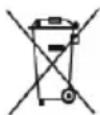
Li-ion
At the end of their working life, dispose of batteries safely in an eco-friendly manner. Batteries contain material classified as hazardous for you and the environment. They must be removed and disposed of separately at a facility cepts lithium-ion batteries.

Separate waste collection of the products and packaging used allows the materials to be recycled and reused. Reuse of recycled materials help to prevent environmental pollution and reduces the demand for raw materials.
2.5 RESIDUAL RISKS
Even when all safety rules are observed, there may still be certain residual risks which cannot be excluded. From the kind and construction of the tool the foreseeable potential endangerments can be:
- Hurled materials that may injure the eyes;
- Damage of the hearing, if no protection of the ears is carried.
3. ABOUT THE MACHINE
3.1 MACHINE DESCRIPTION AND INTENDED USE
This machine is a garden tool and more precisely a battery-powered portable brush cutter/grass trimmer.
The machine essentially comprises of a motor which drives a cutting means configured in various ways to meet various functions.
The operator is able to sustain the machine with the aid of a harness and can operate the main controls, always keeping at a safe distance from the cutting means.
3.1.1 Intended use
This machine was designed and manufactured for:
- cutting grass and non-woody vegetation with a nylon line enclosed in a cutting line head;
- cutting tall grass, dry branches, twigs and woody shrubs of up to 2cm diameter, with the aid of metal or plastic blades;
– being used by one operator.
3.1.2 Improper use
Any other use that does not comply with the above, can be dangerous and cause damage to people and/or property. Examples of improper use may include, but are not limited to:
- using the machine for sweeping, tilting the cutting line head. The power of the motor could throw objects and small stones 15 metres or more, causing damage or injury to people;
– trimming hedges or other jobs in which the cutting means is not used at ground level;
- cutting and chopping trees, bushes and flowers;
- pruning trees;
- using the machine for cutting non-plant material;
- using the machine with the cutting means above the operator's belt level;
- using the machine in public gardens, parks, sports centres, on roadways, fields and woods;
- using cutting means other than those listed in the "Technical Data" table. Serious injury and wound hazard.
- using of the machine by more than one person.
IMPORTANT Improper use of the machine will invalidate the warranty, waive the Manufacturer from all liability, and the user will consequently be liable for all and any damage or injury to himself or others.
3.1.3 Type of users
This machine is intended for use by consumers, i.e. non-professional operators. It is intended for "DIY" use only.
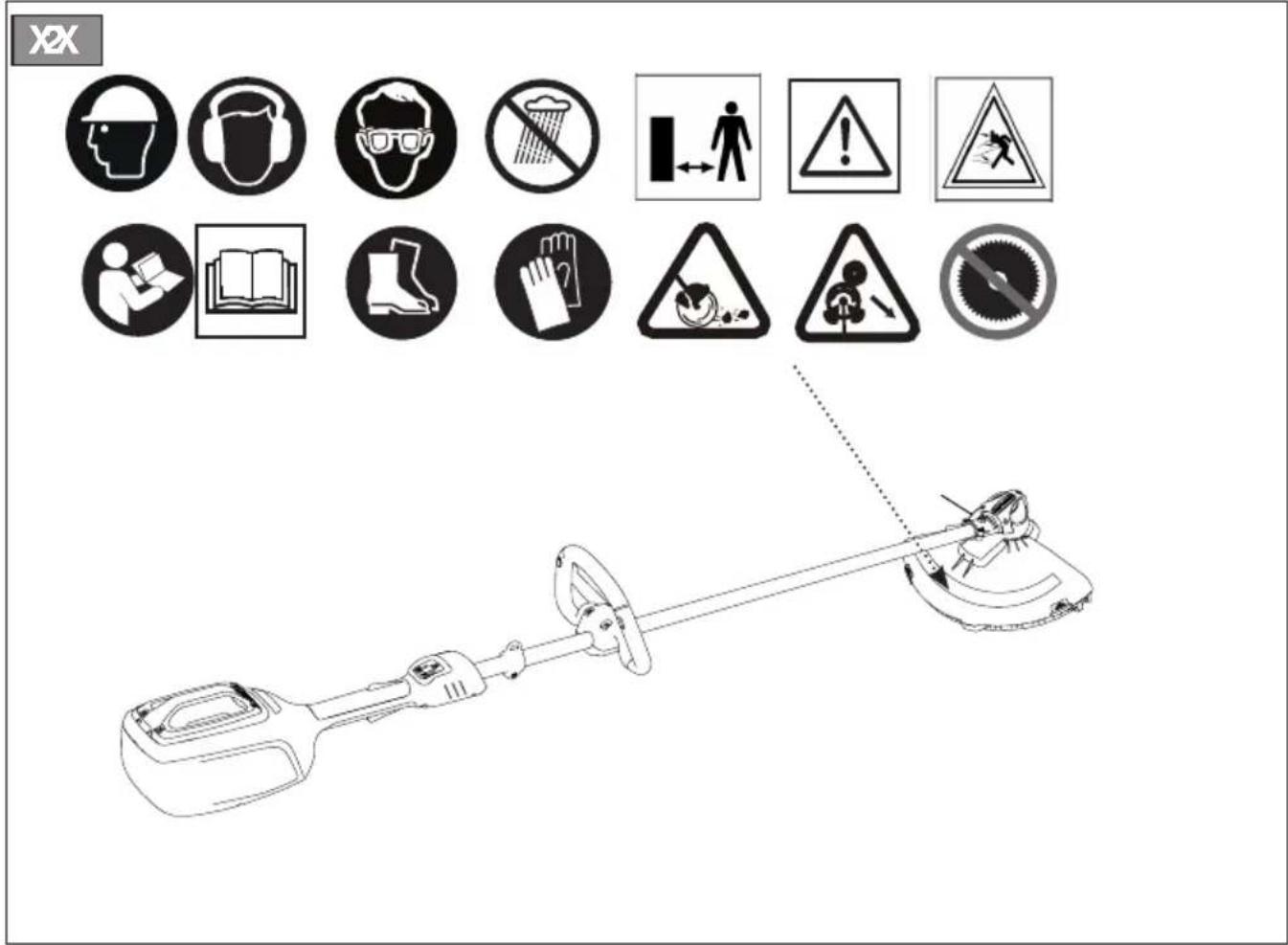
3.2 SAFETY SIGNS
The machine has various symbols on it (fig. 2). Their function is to remind the operator of the correct conduct for use, with due care and caution.
Meanings of the symbols:

WARNING! DANGER! The failure to use this machine correctly can be hazardous for oneself and others.


WARNING! Read the owner's manual before using the machine.


Wear ear protectors, safety goggles and a protective helmet.


Wear protective gloves and safety footwear.

PROJECTION HAZARD!
Be careful of flying debris projected by the cutting means, that can cause serious injuries to persons or damage to things.
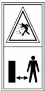
KEEP BYSTANDERS AWAY!
People or pets must be kept at least 15m away when using the machine for projection hazard.
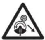
Beware of blade kickback.

Do not use circular saw blades. Danger: using circular saw blades on models that are not designed for them exposes the user to the risk of very serious or even fatal injuries.

Do not leave the machine in the rain (or in damp conditions).
IMPORTANT Any damaged or illegible decals must be replaced. Order replacement decals from an Authorised Service Centre.
3.3 PRODUCT IDENTIFICATION LABEL
The product identification label provides the following data (fig. 1):
- Sound power level
- Conformity marking
- Year of manufacture
- Type of machine
- Manufacturer's reference model
- Serial number
- Name and address of Manufacturer
- Article code
Write the identification data of the machine in the specific space on the label on the back of the cover page.
IMPORTANT Quote the information on the product identification label whenever you contact an Authorised Service Centre.
IMPORTANT An example of the Declaration of Conformity is provided on the last pages of this manual.
3.4 MAIN COMPONENTS
The machine is composed of a series of main components that have the following functions (Fig.1):
A. Engine: drives cutting means motion via transmission shaft and angle transmission.
B. Rod: it connects the rear hand grip to the power unit.
C. Cutting means: the element designed to cut vegetation
-
Cutting line head: nylon line cutting means.
-
3, 4 -point blade: metal disc cutting means (in the box).
D. Cutting means guard: it is a safety device which prevents objects drawn up by the cutting means from being hurled away from the machine.
E. Front hand grip: semi-circular shaped, it is used to handle the machine and is equipped with a leg guard.
F. Rear hand grip: used to handle the machine and equipped with the main on/off/acceleration control buttons.
G. Handle bar: "cow horn" handle bar placed transversely to the rod and asymmetrically to it; used to control the machine and equipped, on the right hand side, with the main on/off/acceleration control buttons.
H. Leg guard: a safety guard that prevents accidental contact with the cutting means during use.
I. Harness: device made up of a fabric belt which, placed over the shoulders, helps to support the weight of the machine during work.
-
single strap
-
double strap
J. Connection point (of the harness): where the harness is connected to the machine.
K. Blade protection (for machine transport and handling): protects against accidental contact with the cutting means that can cause serious injuries.
L. Battery (if not supplied with the machine, see par. 15.1. "accessories on request): device that supplies electric current to the tool; its specifications and regulations for use are described in a specific manual.
M. Battery charger (accessory available upon request, paragraph 15.2): device used to recharge the battery. Two battery charger models are available: M1 (fast battery charge); M2 (standard battery charge).
N. Battery backpack (attachment on request, par. 15.3): device in which the batteries are placed.
O. Connection cable: cable used to connect the machine to the battery backpack.
P. Battery simulator (attachment on request, par. 15.4): device that, if inserted in the machine housing, allows the use of the battery backpack.
4. ASSEMBLY
IMPORTANT The safety regulations to follow are described in chap. 2. Strictly comply with these instructions to avoid serious risks or hazards.
For storage and transport purposes, some components of the machine are not installed in the factory and have to be assembled after unpacking. Follow the instructions below.
⚠️ Unpacking and completing the assembly should be done on a flat and stable surface, with enough space for machine handling and its packaging, always making use of suitable equipment. Do not use the machine until all the instructions provided in the “ASSEMBLY” section have been carried out.
4.1 ASSEMBLY COMPONENTS
The packaging includes assembly components.
4.1.1 Unpacking
- Carefully open the packaging, paying attention not to lose components.
- Consult the documentation in the box, including these instructions.
- Remove all the unassembled parts from the box.
- Remove the machine from the box.
- Dispose of the box and packaging in compliance with local regulations.
⚠️ Before assembling, make sure the battery is not inserted in its housing.
4.2 GRIP ASSEMBLY
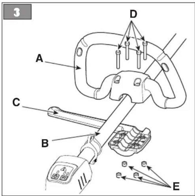
4.2.1 Assembly of the front hand grip
- Position the front handle (Fig. 3.A) on the rod (Fig. 3.B).
- Assemble the leg guard (Fig. 3.C) on the hand grip making sure it faces to the left.
- Attach the handle to the leg guard with screws (Fig. 3.D) and nuts (Fig. 3.E).
4.2.2 Fitting the handle bar
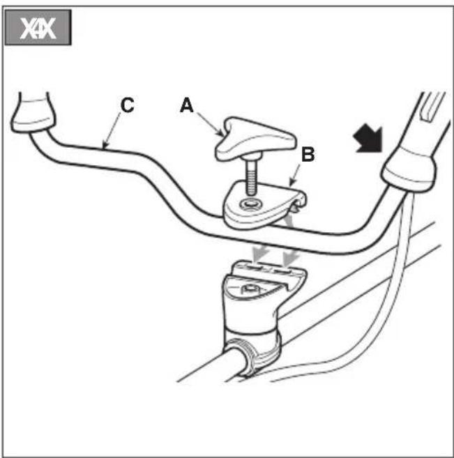
- Unscrew the central knob (Fig. 4.A) and remove the cap (Fig. 4.B).
- Insert the handle bar (Fig. 4.C), making sure that the controls are on the right.
- Arrange the handle bar in the most comfortable working position and lock it using the cap (Fig. 4.B) and the knob (Fig. 4.A).
NOTE Loosen the knob (Fig. 4.A) in order to rotate the handle bar and reduce its overall dimensions for storage purposes.
4.3 FITTING/REMOVING CUTTING MEANS AND SPECIFIC GUARDS

Wear protective gloves.
IMPORTANT When the cutting means has to be changed, remove the battery from its housing and dismantle all the parts.
4.3.1 Selecting the cutting means
Choose the most suitable cutting means for the job to be done, according to these general instructions:
- the cutting line head can cut tall grass and non-woody vegetation near fences, walls, foundations, pavements, around trees, etc. or to clear a particular area of the garden;
- the 3 -point and 4-point blades are suitable for cutting brushwood and small shrubs up to 2 cm in diameter.
4.3.2 Fitting the guard on the cutting means
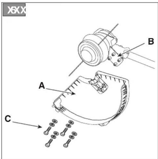
- Align the guard (Fig. 5.A) with the motor unit holes (Fig. 5.B).
- Fully tighten the screws (Fig. 5.C).
NOTE On the guard of the cutting means there is the following symbol:

It indicates the rotation direction of the cutting means.
4.3.3 Fitting and removing cutting means
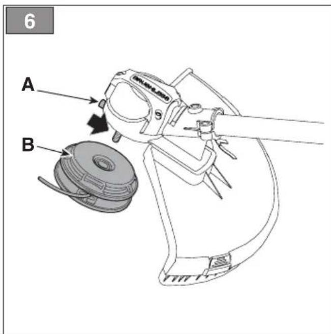
4.3.3.a Fitting the cutting line head
- Press the button (Fig. 6.A) and hold it down whilst turning the head until it clicks into place, locking the crankshaft and the whole body of the wire head (Fig. 6.B).
- Fit the cutting line head (Fig. 6.B) screwing it clockwise.
IMPORTANT When using the cutting line head, the line cutting knife must always be installed (Fig. 7.A). The machine is delivered with a cutting diameter set to 38cm.
4.3.3.b Removing cutting wire head
- Press the button (Fig. 6.A) and hold it down whilst turning the head (Fig. 6.B) until it clicks into place, locking the crankshaft and the whole body of the wire head.
- Remove the wire head (Fig.6.B) by unscrewing it counter clockwise.
4.3.3.c Fitting the 3-point, 4 -point blade

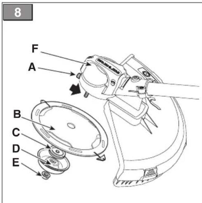
Apply the guard to the blade.
- Mount the blade (Fig. 8.B) and the outer ring nut (Fig. 8.C) with the wider part facing the blade.
- Mount the outer cup (Fig. 8.D) without tightening the nut (Fig. 8.E).
- Press the button (Fig. 8.A) and rotate the blade by hand (Fig. 8.B) until it engages in the hole in the inner ring nut, thereby blocking rotation.
- Tighten the nut (Fig. 8.E) fully clockwise using the wrench provided.
- Remove the wrench to restore rotation.
4.3.3.d Removing the 3-point, 4-point blade

Apply the guard to the blade.
- Press the button (Fig. 8.A) and rotate the blade by hand (Fig. 8.B) until it engages in the hole in the inner ring nut, thereby blocking rotation.
- Unscrew the nut (Fig. 8.E) anti-clockwise and remove the outer cup (Fig. 8.D).
- Remove the outer ring nut (Fig. 8.C), then remove the blade (Fig. 8.B).
4.4 FITTING OF THE BATTERY BACKPACK (IF AVAILABLE)
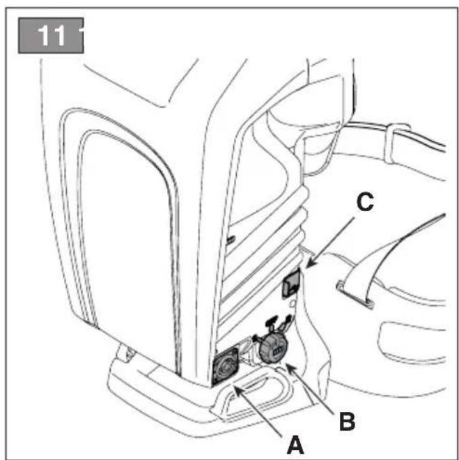
The battery backpack is delivered already assembled (Fig. 1N) and can be released from the strap support (Fig. 9) and carried by hand. To release the battery backpack, press on the two upper buttons (Fig. 9.A). The battery compartments are located on both sides of the backpack (Fig. 10) The following can be found on the right side of the backpack:
• cable socket (Fig. 11.A)
- battery selector (Fig. 11.B)
- one USB port for charging other devices (e.g. mobile phones) (Fig. 11.C)
To avoid any loose cables, there are grooves on both sides and at the rear, in which the power cable can be inserted.
5. CONTROLS

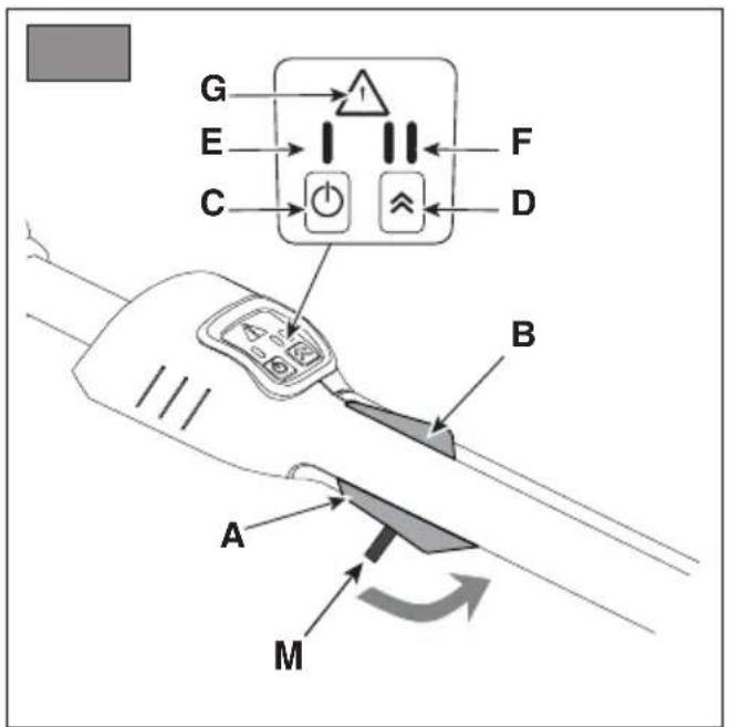
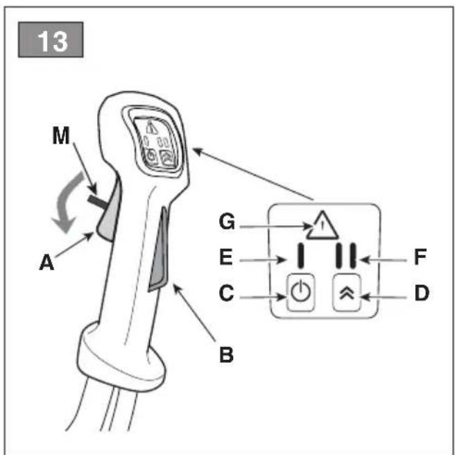
Press this button (Fig. 12.C, Fig.13.C) to activate and deactivate the machine's electrical circuit; the corresponding LED switches on (Fig. 12.E, Fig. 13.E).

Press the speed button (Fig.12.D, Fig.13.D) to set the cutting speed; the 2 corresponding LEDs switch on (Fig. 12.F, Fig. 13.F). If work is interrupted (without turning off the machine), the machine will resume at the previously set speed.
Lights off: the electrical circuit is completely deactivated (OFF).
IMPORTANT Do not keep your finger on the button when moving the machine to avoid accidentally enabling the machine.

The "Warning" icon (Fig. 12.G, Fig. 13.G) switches on in the event of machine fault (refer to the troubleshooting table, par. 14).
5.2 THROTTLE CONTROL LEVER
Used to start and regulate cutting means speed.
The throttle safety lever (Fig. 12.A, Fig. 13.A) can be used only if the throttle safety lever (Fig. 12.B-M, Fig. 13.B-M) is pressed at the same time.
The cutting means stops automatically when the throttle safety lever is released.
5.3 THROTTLE SAFETY LEVER
The throttle safety lever (Fig. 12.B-M, Fig. 13.B-M). allows the throttle control lever to be used (Fig. 12.A, Fig. 13.A).
6. USING THE MACHINE
IMPORTANT The safety regulations to follow are described in chap. 2. Strictly comply with these instructions to avoid serious risks or hazards.
6.1 PRELIMINARY OPERATIONS
Before starting work it is necessary to carry out several checks and operations to ensure you can work efficiently and in maximum safety:
- make sure the battery is not inserted in its housing;
- place the machine in a stable horizontal position on the ground;
- choose the most suitable cutting means for the job to be done (par. 4.3.1);
- check the battery (par. 6.1.1);
- wear the harness correctly (par. 6.1.2).
6.1.1 Checking the battery
The machine is supplied without the battery.
Purchase the battery with the capacity that most suits your operational requirements and fully charge it according to the instructions in the battery booklet.
The list of approved batteries for this machine can be found in the "Technical Data" table.
Before each use:
– check the battery charge status according to the instructions in the battery booklet.
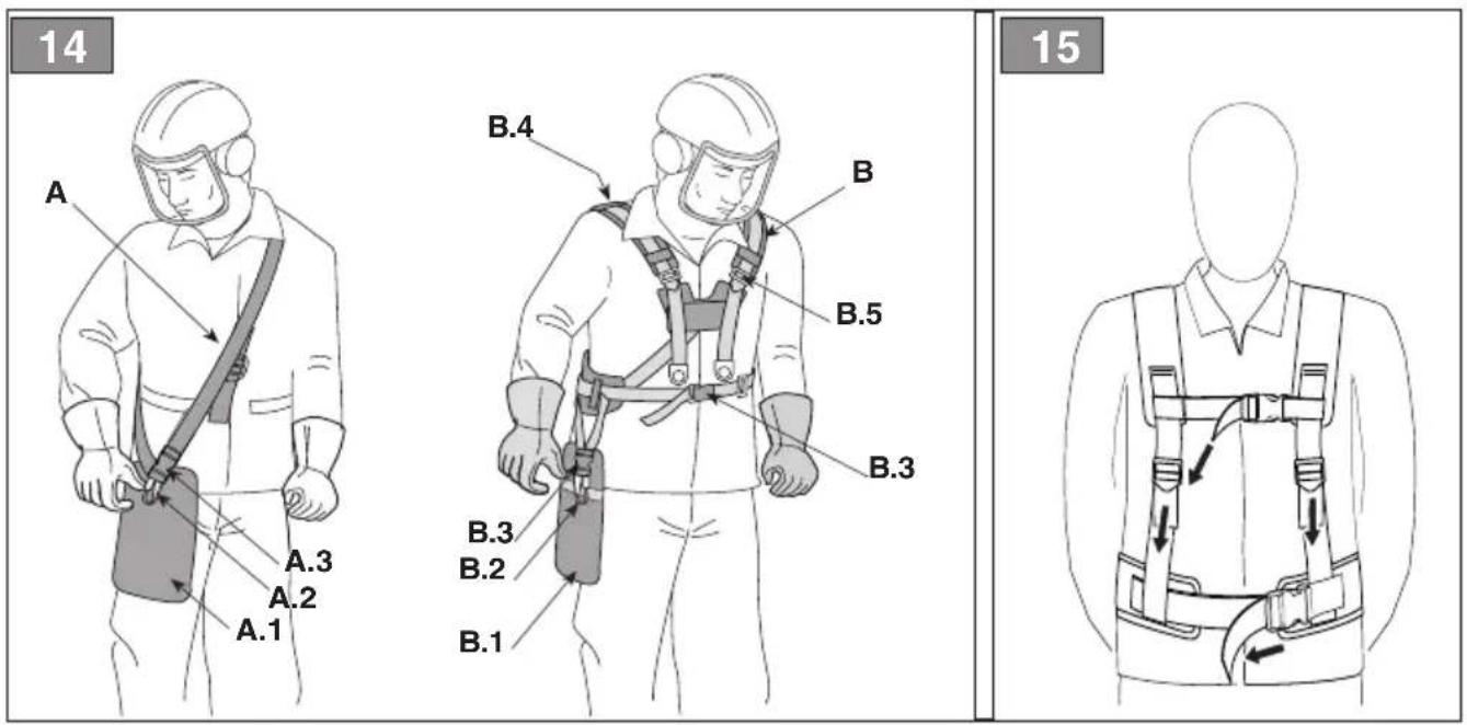
6.1.2 Using the harness
The harness must be put on before connecting the machine to the special coupling and the belts must be adjusted to suit the operator's height and build.
Always use an appropriate harness for the weight of the machine:
– for machines weighing less than 7.5 kg, single or double strap models can be used;
- for machines weighing more than 7.5 kg, only the double strap model should be used.
- Single strap models
The harness must be worn before securing the machine to the attachment.
The strap (Fig. 14.A) must pass over the left shoulder, towards the right side.
The strap must be worn with:
– the support (Fig. 14.A.1), the machine's carabiner hook (Fig.14.A.2). and the quick release hook (Fig. 14.A.3) on the right side.
- Double strap models
The harness must be worn before securing the machine to the attachment.
The strap (Fig. 14.B) must be worn with:
– the support (Fig. 14.B.1), the machine's carbine hook (Fig. 14.B.2) and the quick release (Fig. 14.B.3) located on the right side.
– the quick release at the front (Fig. 14.B.3);
– the strap crossover on the back of the operator (Fig. 14.B.4);
– the buckles correctly fastened (Fig. 14.B.5).
The straps must be tightened so that they distribute the load evenly over the shoulders.
6.1.3 Use of the backpack (if available)
-
Insert the battery in one of the compartments of the battery backpack (Fig. 10) and push it completely, until hearing the click that signals its locking in position, ensuring thus the electrical contact;
-
Connect the cable to the backpack in the specific socket (Fig. 11.A) and rotate it until hearing the specific click that signals its locking in position, ensuring thus the electrical contact;
-
adjust the straps and close the harness in the front (Fig. 15).
6.2 SAFETY CHECKS
Run the following safety checks and ensure that the results correspond to those outlined in the tables.
⚠️ Always carry out the safety checks before use.
6.2.1 General check
| Object Result | |
| Hand grips (Fig. 1.E; Fig. 1.G). | Clean, dry and fixed firmly to the machine. |
| Cutting means guard (Fig. 1.D). | Correctly and securely fit to the machine, not worn/ deteriorated or damaged. |
| Harness connection point (Fig. 1.J). | Correctly positioned. |
| Screws on the machine and the cutting means. | Correctly tightened (not loose). |
| Cutting means (Fig. 1.C.1; Fig. 1.C.2). | Clean, not damaged or worn. |
| Metal blade (if fitted) (Fig. 1.C.2). | Sharp. |
| Battery (Fig. 1.L) No damage to the casing, no liquid leakage. |
| Cooling air ducts (paragraph 7.3). | Not clogged. |
| Machine | No signs of damage or wear. |
| Throttle control lever (Fig. 12.A Fig. 13.A), throttle safety lever (Fig. 12.B, Fig. 13.B). | The levers must move freely and not be forced. |
| Test driving | No abnormal vibrations. No abnormal sound. |
6.2.2 Machine operating test
| Action Result | |
| 1. Fit the battery inside its housing (par. 7.2.3);2. Press the safety button (Fig. 12.C, Fig. 13.C) | The LED (Fig. 12.E, Fig. 13.E) must switch on (electrical circuit activated). |
| 1. Start the machine (para. 6.3);2. operate the throttle control lever (Fig. 12.A Fig. 13.A) and throttle safety lever (Fig. 12.B, Fig. 13.B) at the same time;3. release the throttle control lever (Fig. 12.A Fig. 13.A) and throttle safety lever (Fig. 12.B, Fig. 13.B). | 1. The cutting means must not move.2. The cutting means should move.3. The levers should return automatically and rapidly to the neutral position and the cutting means should stop. |
| Press only the throttle control lever (Fig. 12.A, Fig. 13.A). | The throttle control lever remains blocked. |
If any of the results fail to match the indications provided in the tables below, do not use the machine! Take it to a service centre to be checked and repaired if necessary.
6.3 START-UP
6.3.1 Start-up with battery
- Remove the blade guard (Fig. 1.K) (if used);
- Make sure the cutting means is not touching the ground or any other object;
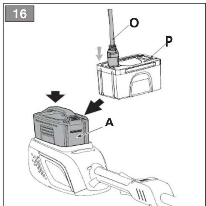
- insert the battery correctly in its compartment (Fig. 16) (par. 7.2.3);
- Press the safety button (Fig. 12.C, Fig. 13.C); operate the throttle control lever (Fig. 12.A Fig. 13.A) and throttle safety lever (Fig.
12.B-M, Fig. 13.B-M) at the same time.
6.3.2 Start-up with battery simulator (if available)
- Remove the blade guard (Fig. 1.K);
- Make sure the cutting means is not touching the ground or any other object;
- Insert the battery simulator (Fig. 16.P) correctly in its compartment on the machine (Fig.16.A)
- connect the connection cable (Fig. 16.O) to the battery simulator
- select the battery using the selector (Fig. 11.B)
- press the safety button (Fig. 12.C, Fig. 13.C)
- press the throttle control (Fig. 12.A, Fig. 13 A)
6.4 OPERATION
NOTE Before starting any tasks for the first time, get to know the machine, learn the most suitable cutting techniques, make sure your are wearing the harness correctly, grip the machine firmly and make the movements required by the job.
To use the machine proceed as follows:
– always keep the machine connected to the correctly worn harness (see par. 6.1.2).
– when working, the machine must always be firmly held in both hands, keeping the power unit on the right of the body and the cutting unit below the line of the belt.
NOTE During use, the battery is protected against total drainage with a protective device that switches off the machine and stops it from working.
NOTE Battery power reserve (and therefore the cuttable vegetation area before recharging is required) depends on many factors described in (par. 7.2.1).
NOTE After one minute of inactivity, if turned on, the machine will automatically switch off.
6.4.1 Work techniques
6.4.1.a Cutting line head
⚠ Use ONLY nylon lines. The use of metal lines, plastic coated metal lines and/or lines that are not suitable for the head can cause serious injuries and wounds.
a. Cutting motion (Scything)
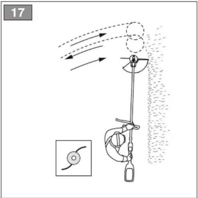
Proceed at a steady pace, with a circular motion similar to a traditional scythe, without tilting the cutting line head during the operation (Fig. 17).
Start cutting at the correct height in a small area, so as to achieve a uniform cutting height keeping the cutting line head at a constant distance from the ground.
For heavier cutting it can be useful to tilt the cutting line head to the left by about 30^ .
Do not work in this way if there is the possibility of causing objects to be thrown, which could harm people, animals or cause damage.
b. Precision cutting (Trimming)
Keep the machine slightly tilted so that the lower part of the cutting line head does not touch the ground and the cutting line is at the required point, always keeping the cutting means at a distance from the operator.
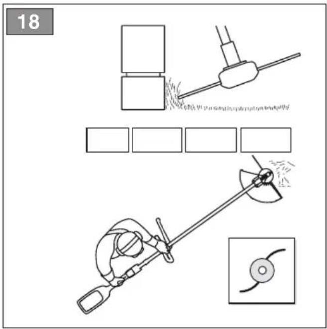
c. Cutting near fences/foundations
Move the cutting line head slowly towards fences, posts, rocks, walls, etc. without hitting them hard (Fig. 18).
If the line strikes a solid object it could break or become worn; if it gets tangled in a fence it could break suddenly.
In any case, cutting around pavements, foundations, walls, etc. can cause greater wear than normal to the line.
d. Cutting around trees
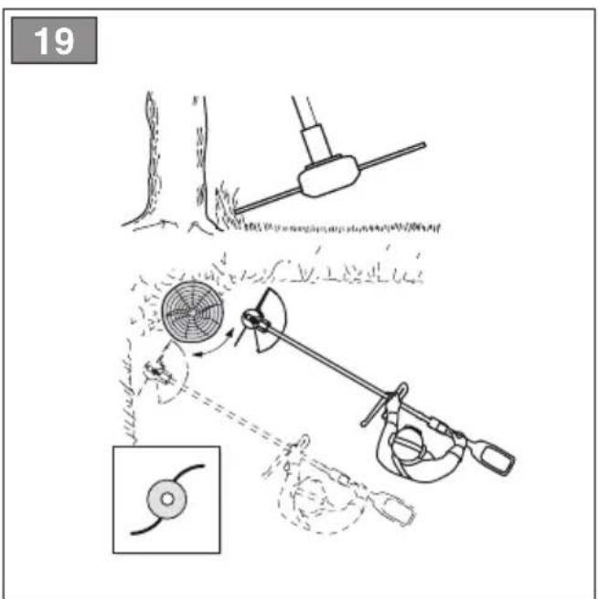
Walk round the tree from left to right, approaching the trunk slowly so as not to strike the tree with the line and keeping the cutting line head tilted forward slightly (Fig. 19).
Remember that the nylon line could lop off or damage small shrubs and that the impact of the nylon line against the trunk of bushes or trees with soft bark could seriously damage the plant.
6.4.1.b 3-point, 4-point blade
Start cutting from above the vegetation and then descend with the mowing blade to cut branches by chopping them into small pieces (Fig. 20).
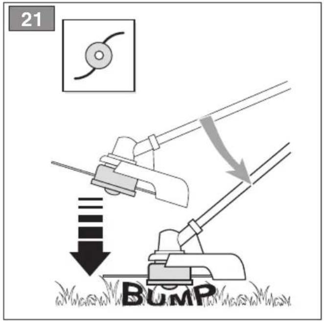
6.4.2 Adjusting the length of the cutting line head during work
This machine is fitted with an automatic line release head.
Head line length should be adjusted:
- when the line is consumed and becomes shorter;
- when engine rotation seems higher than normal;
- when cutting efficiency seems reduced.
To release new line:
- hit the cutting line head against the ground (Fig. 21) with the throttle control lever pressed fully down;
- line is automatically released and the line cutting knife (Fig. 7.A) cuts the excess length.
6.5 OPERATING SUGGESTIONS
During use it is advisable to periodically remove weeds that wrap around the machine to avoid the
motor overheating (Fig. 1.A), as well as under the cutting means guard (Fig. 1.D).
Proceed as follows:
- stop the machine (par. 6.6);
- remove the battery (par. 7.2.2);
- wear protective gloves;
- remove the entangled grass with a screwdriver to allow the motor to cool properly.
6.6 STOP
To stop the machine:
- release the throttle control lever (Fig. 12.A, Fig. 13.A);
- deactivate the safety button (Fig. 12.C, Fig. 13.C);
- Wait until the cutting means stops.
When you have stopped the machine, it will take a few seconds for the cutting means to stop.
IMPORTANT Always stop the machine when moving between work areas.
⚠ Do not keep your finger on the safety button when moving the machine to avoid accidentally enabling the machine.
6.7 AFTER USE
6.7.1 After use with the battery
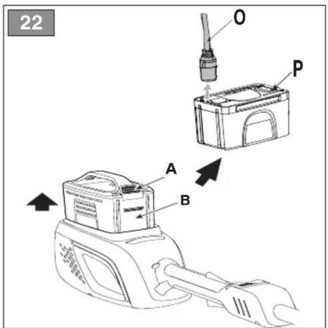
- Remove the battery from its compartment (Fig. 22.B) and recharge it (par 7.2.2).
- Fit the blade guard (Fig. 1.K) when the cutting means is stopped.
- Allow the engine to cool before storing in an enclosed space.
- Clean (par. 7.3).
- Make sure there are no loose or damaged components. If necessary, replace the damaged components and tighten any screws and loose bolts or contact the authorised service centre.
6.7.2 After use with battery simulator (if available)
- Move the battery backpack selector to "OFF" (Fig. 11.B);
- remove the battery simulator from the machine (Fig. 22.P);
- remove the battery backpack;
- disconnect the connection cable from the battery simulator (Fig.22.O) and from the backpack (fig. 11.A)
- remove the battery from the backpack (Fig. 23) and charge it (par. 7.2.2);
- allow the engine to cool before storing the machine in an enclosed space;
- Clean (para. 7.3);
- Make sure there are no loose or damaged components. If necessary, replace the damaged components and tighten any screws and loose bolts or contact the authorised service centre.
IMPORTANT Always remove the battery (par 7.2.2) and fit the glade guard whenever you leave the machine unused or unattended.
7. ROUTINE MAINTENANCE
IMPORTANT The safety regulations to follow are described in chap. 2. Strictly comply with these instructions to avoid serious risks or hazards.
Prior to carrying out any maintenance operation, you need to:
- stop the machine;
- remove the battery from its housing and recharge it (par 7.2.2);
- when the cutting means is stationary, apply the blade protection cover, (except when working directly on the blade);
- allow the engine to cool before storing in an enclosed space;
- use suitable clothing, protective gloves and goggles;
- read the relevant instructions.
- The frequency and types of maintenance are summarised in the "Maintenance Table" (chapter 13). The table will help you maintain your machine's safety and performance. It summarises the main interventions to be made and the frequency applicable to each
of them. Carry out the relevant task as soon as it is scheduled to be performed.
- The use of non-original parts and accessories could have negative effects on machine operation and safety. The manufacturer declines any responsibility for damage or injury caused by said products.
– Genuine spare parts are supplied by Authorised Assistance Centres and Dealers.
IMPORTANT Any maintenance and adjustment operations not described in this manual must be carried out by your dealer or Authorised Service Centre.
7.2 BATTERY
7.2.1 Battery power reserve
Battery power reserve (and therefore the cuttable vegetation area before recharging is required) mainly depends on:
a. Environmental factors, that cause higher energy requirements:
– cutting, high, wet vegetation;
b. operator behaviour that should be avoided:
– switching the machine on and off frequently whilst working;
– using a cutting means or cutting technique that is unsuitable for the work to be performed (par. 6.4);
– cutting speed unsuitable for the condition of the grass to be cut.
To optimise battery power reserve it is always recommended to:
• cut the grass when dry;
- set a cutting speed suitable for the condition of the grass;
- use the most appropriate cutting means and technique for the work to be performed.
If the need arises to use the machine for sessions which exceed the capability of a standard battery, it is possible to:
• purchase a second standard battery to immediately replace the discharged battery, without compromising the continuity of operations;
• purchase a battery with an extended power reserve compared to the standard version (para. 15.1).
7.2.2 Battery removal and recharging
-
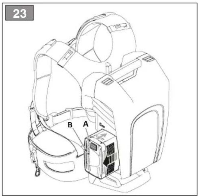
Press the locking button located on the battery on the machine (Fig. 22.A) or on the backpack (Fig. 23.A) (if available);
-
remove the battery from the machine (Fig. 22.B) or from the battery backpack (Fig. 23.B) (if available);
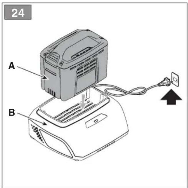
- Fit the battery (Fig. 24.A) in the battery charger compartment (Fig. 24.B);
- Connect the battery charger (Fig. 24.B) to a power socket with the voltage indicated on the rating plate;
- Fully charge the battery according to the instructions in the battery/battery charger booklet.
NOTE The battery is equipped with a guard that inhibits recharging if the environmental temperature is not between 0 and +45°C.
NOTE The battery can be recharged at any time, even partially, with no risk of damaging it.
7.2.3 Refitting the battery on the machine
When recharging is completed:
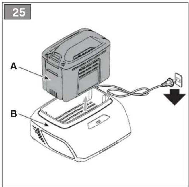
- Remove the battery (Fig. 25.A) from the housing in the battery charger (do not keep charging when recharging is completed);
- Disconnect the battery charger (Fig. 25.B) from the electrical mains;
- insert the battery in its compartment on the machine (Fig. 16.A) or in one of the compartment of the battery backpack (Fig. 10) (if available)
- push it completely, until hearing the click that signals its locking in position, ensuring thus the electrical contact.
7.3 CLEANING THE MACHINE AND THE ENGINE
• Always clean the machine after use with a damp cloth dipped in neutral detergent.
- Remove all traces of humidity using a soft damp cloth. Humidity can generate risks of electric shocks.
- Do not use aggressive detergents or solvents to clean the plastic parts or hand grips.
- To reduce fire hazards, keep the machine and, in particular, the motor free of grass, leaves, or excessive grease.
- To avoid overheating and damage to the motor or battery, always keep the cooling air vents (Fig. 26) clean and free of debris.
- Do not spray water onto the motor and electrical components and prevent them from getting wet.
7.4 NUTS AND BOLTS
- Keep all nuts, bolts and screws tight to be sure the equipment is in safe working condition.
- Check regularly that the handles are fixed firmly.
8. OCCASIONAL MAINTENANCE
8.1 CUTTING MEANS MAINTENANCE
When servicing the cutting means, bear in mind that the cutting means can still move even if the battery has been removed from its housing.
Cutting means displaying the code indicated on the Technical Data table should only be used on this machine.
Given product evolution, the cutting means mentioned in the "Technical Data" table may be replaced in time with others having similar interchangeable and operating safety features.
Do not touch the cutting means until the battery has been removed and the cutting means is completely stationary.
⚠ Warning! Risk of injuries due to dangerous moving parts!
8.1.1 Blade sharpening/balancing
⚠ For safety reasons, sharpening and balancing should be performed by an Authorised Service Centre with suitable skills and equipment for the job; without risking any damage to the blade which would make it unsafe when used.
Blades can be used on both sides. When one side of the points is worn, the blade can be turned and the other side used.
When both sides of the points are worn, have them sharpened.
8.1.2 Blade replacement
The blade must never be repaired, but must be replaced as soon as signs of breaking are noted or the sharpening limit is exceeded:
For replacement procedures, see chapter 4.3
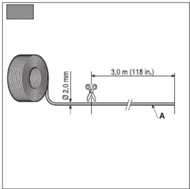
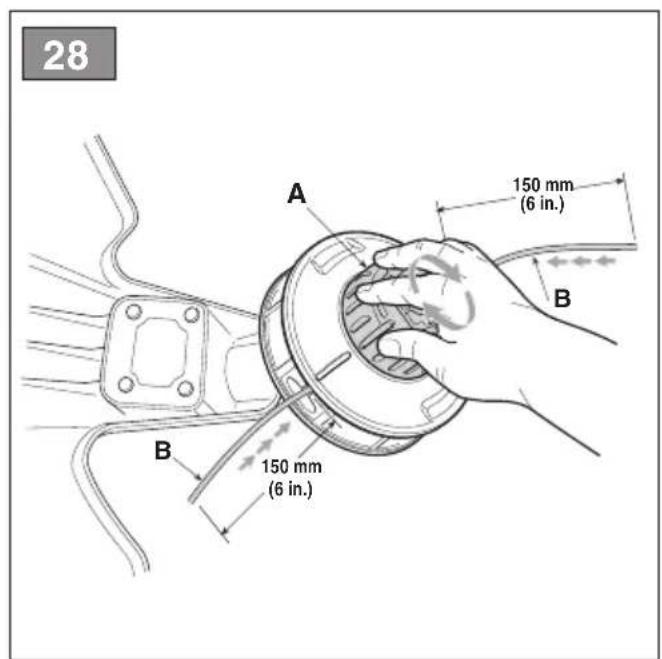
8.1.3 Replacing the cutting line head
- Only use lines of 2 mm in diameter and cut the new line to the indicated length (Fig. 27.A).
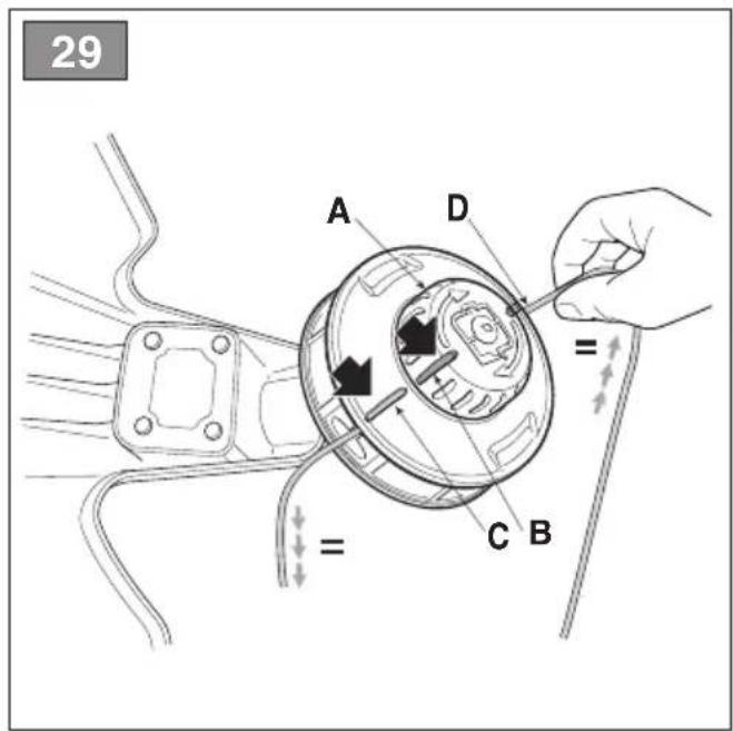
- Turn the winding knob (Fig. 28.A) to align the reference on the knob (Fig. 29.B) with the reference on the head body (Fig. 29.C).
- Insert one end of the line (Fig. 29.D) in one of the two output holes and pass the line through the opposite hole.
- Align the lines that exit the two holes evenly.
- Turn the winding knob (Fig. 28.A) following the direction of the arrows to wind the line, being careful to leave about 150 mm from both holes (Fig. 28.B).
If old line is left in the head or if broken inside it, remove as described below:
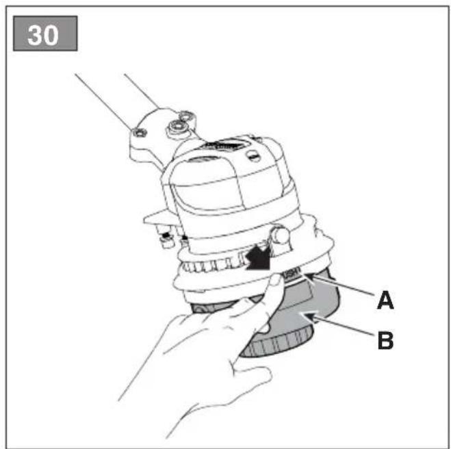
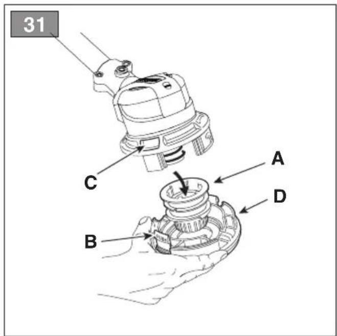
- Press the tabs on the sides of the cutting line head, where marked "PUSH" (Fig. 30.A), and detach the lower part of the head (Fig. 30.B);
- Remove the line left inside;
- Replace the reel (Fig. 31.A) in its housing;
- Close the head by fastening the tabs (Fig. 31.B) in the slots (Fig. 31.C), pushing them fully in until they click to lock the bottom part of the head (Fig. 31.D) in place.
8.2 SHARPENING THE WIRE CUTTING BLADE
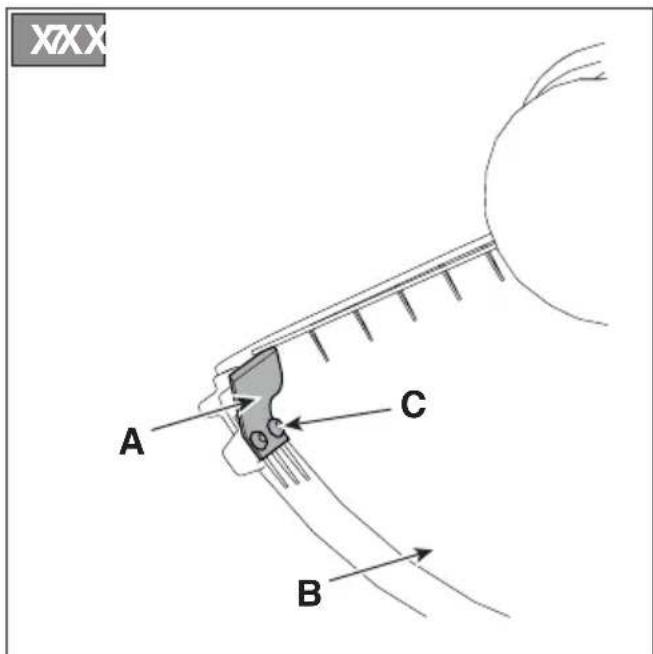
- Remove the line cutting knife (Fig. 7.A) from the cutting means guard (Fig. 7.B) by unscrewing the screws (Fig. 7.C).
- Fix the line cutting knife in a vice and sharpen it using a flat file, being careful to retain the original cutting angle.
- Refit the line cutting knife (Fig. 7.A) on the cutting means guard (Fig. 7.B) and tighten the screws (Fig. 7.C).
9. STORAGE
IMPORTANT The safety regulations to follow are described in chap. 2. Strictly comply with these instructions to avoid serious risks or hazards.
9.1 STORING
When the machine is to be stored away:
9.2 STORING THE BATTERY
The battery must be kept in a cool, shaded place without humidity.
NOTE If unused for any length of time, recharge the battery every two months to prolong its working life.
10. HANDLING AND TRANSPORT
Whenever the machine is to be handled or transported you must:
- stop the machine (par. 6.6);
- remove the battery from its housing and recharge it (par. 7.2.2);
- when the cutting means has halted, fit the blade guard;
- wear protective work gloves;
- only hold the machine using the hand grips and position the cutting means in the opposite direction to that used during operations.
When transporting the machine on a vehicle, always:
– fasten the machine securely with cables or chains;
- position it so that it does not cause a hazard to anyone.
11. ASSISTANCE AND REPAIRS
This manual provides all the necessary information to run the machine and for correct basic maintenance operations which can be performed by the user. Any regulations and maintenance operations not described herein must be carried out by your Dealer or Authorised Service Centre, which have the necessary knowledge and equipment to ensure that the work is carried out correctly, maintaining the correct degree of safety and the original operating conditions of the machine.
Any operations performed in unauthorised centres or by unqualified persons will totally invalidate the warranty and all obligations and responsibilities of the manufacturer.
- Only Authorised Service Centres can carry out guaranteed repairs and maintenance.
- The Authorised Service Centres only use genuine spare parts. Genuine spare parts and attachments have been designed specifically for machines.
- Non-genuine spare parts and accessories are not approved. Use of non-genuine spare parts and accessories cause the warranty to be voided.
- It is advisable to send your machine once a year to an Authorised Service Centre for servicing, assistance and safety device inspection.
12. WARRANTY COVERAGE
The warranty covers all material and manufacturing defects. The user must follow all
the instructions provided in the accompanying documentation.
The warranty does not cover damage caused by:
- Failure to become familiar with the documentation accompanying the machine.
- Carelessness.
- Incorrect or prohibited use or assembly.
- Use of non-genuine spare parts.
- Use of attachments not supplied or not approved by the manufacturer.
The warranty does not cover:
- Normal wear and tear of consumables, such as cutting means, safety bolts.
• Normal wear and tear.
The purchaser is protected by his or her own national legislation. The purchaser's rights under the national laws or his or her own country are not in any way restricted by this warranty.
13. MAINTENANCE TABLE
| Intervention Frequency Notes | | |
| MACHINE |
| Check all fasteners | Before each use para. | 7.4 |
| Safety checks/check controls | Before each use para. | 6.2 |
| Check the cutting means guard. | Before each use par. | 6.2.1 |
| Checking the cutting means | Before each use par. | 6.2.1 |
| Check the battery charge status | Before each use * | |
| Recharge the battery | After each use para. | 7.2.2* |
| Cleaning the machine and the engine | After each use para. | 7.3 |
| Checking for any damage to the machine. If necessary, contact the authorised service centre. | After each use | - |
* Refer to the battery/battery charger manual.
14. TROUBLESHOOTING
| PROBLEM PROBALE CAUSE SOLUTION | |
| 1. When the safety button is pressed, the two green lights do not come on | Battery is not inserted or is inserted incorrectly | Make sure the battery is inserted and seated correctly in its housing (paragraph 7.2.3) |
| 2. When the safety button is pressed, the LED (Fig. 12.G, Fig. 13.G) blinks | Low battery Check the battery status and recharge if necessary (para. 7.2.2) |
| 3. The motor stops during work and the LED (Fig. 12.G, Fig. 13.G) blinks | Low battery Check the battery status and recharge if necessary (para. 7.2.2) |
| 4. The cutting means is stationary when the throttle control lever and throttle safety lever are engaged | Machine damaged Do not use the machine. Immediately turn off the machine remove the battery and contact an authorised service centre. |
| 5. Motor overheating | Grass trapped under the cutting means guard | Remove trapped grass (par. 6.5) |
| 6. Mowing is difficult | The cutting means is not in good condition | Proceed with cutting means maintenance (par. 8.1) |
| 7. Grass accumulates around the rod housing and cutting line head | Too high grass is being cut close to the ground | Cut tall grass with a sweeping motion to avoid build up. |
| 8. The line is not released when the cutting line head hits the ground | The line is stuck to itself Lubricate with silicone spray |
| Not enough line on the reel or reel empty | Replace the line (chapter 8.1.3.) |
| The line is worn and too short Pull the line whilst pressing the release button |
| The line is tangled on the reel or broken Remove the line from the reel and rewind it (chapter 8.1.3) |
| 9. The cutting means comes into contact with a foreign body. | - Turn off the machine, remove the battery and: - inspect for damage; - check for and tighten any loose parts; - have all replacements or repairs carried out by an authorised service centre. |
| 10. Excessive noise and/or vibration is experienced whilst working | Loose or damaged parts. Turn off the machine, remove the battery and: - inspect for damage; - check for and tighten any loose parts; - have all replacements or repairs carried out by an authorised service centre. |
| 11. The machine gives off smoke whilst working | Machine damaged Do not use the machine. Immediately turn off the machine remove the battery and contact an authorised service centre. |
| 12. Battery power reserve is low | Severe working conditions requiring greater current absorption | Optimise operations (para. 7.2.1) |
| Battery is insufficient for operating requirements | Use a second battery or extended battery (par. 15.1) |
| Decrease in battery capacity Purchase a new battery |
If problems persist after having performed the operations described above, contact your dealer.
| PROBLEM PROBABLE CAUSE SOLUTION | |
| 13. The battery charger is not recharging the battery | Battery is not correctly inserted in the battery charger | Check it is correctly inserted (para. 7.2.2) |
| Unsuitable environmental conditions Recharge the battery in places with suitable temperatures (see battery/battery charger instruction manual) |
| Dirty contacts Clean the contacts | |
| The battery charger is not energised Check it is plugged in and the power socket is energised |
| Faulty battery charger Replace with an original spare part |
| - If the problem persists, refer to the battery/battery charger manual |
| 14. The LED indicator (Fig. 12.G, Fig. 13.G) remains ON in steady mode | Self-check failed Do not use the machine. Immediately turn off the machine, remove the battery and contact an authorised service centre. |
| 15. The LED indicator (Fig. 12.G, Fig. 13.G) remains ON in flashing mode | Battery communication error Do not use the machine. Immediately turn off the machine, remove the battery and contact an authorised service centre. |
| Rotor blocked Do not use the machine. Immediately turn off the machine, remove the battery and contact an authorised service centre. |
| Current overload Optimize machine usage. |
| PCB overheated Do not use the machine. Immediately turn off the machine, remove the battery and contact an authorised service centre. |
If problems persist after having performed the operations described above, contact your dealer.
15. ACCESSORIES ON REQUEST
15.1 BATTERIES
Different capacity batteries are available to suit specific operating requirements (Fig. 32). The list of approved batteries for this machine can be found in the "Technical Data" table.
15.2 BATTERY CHARGER
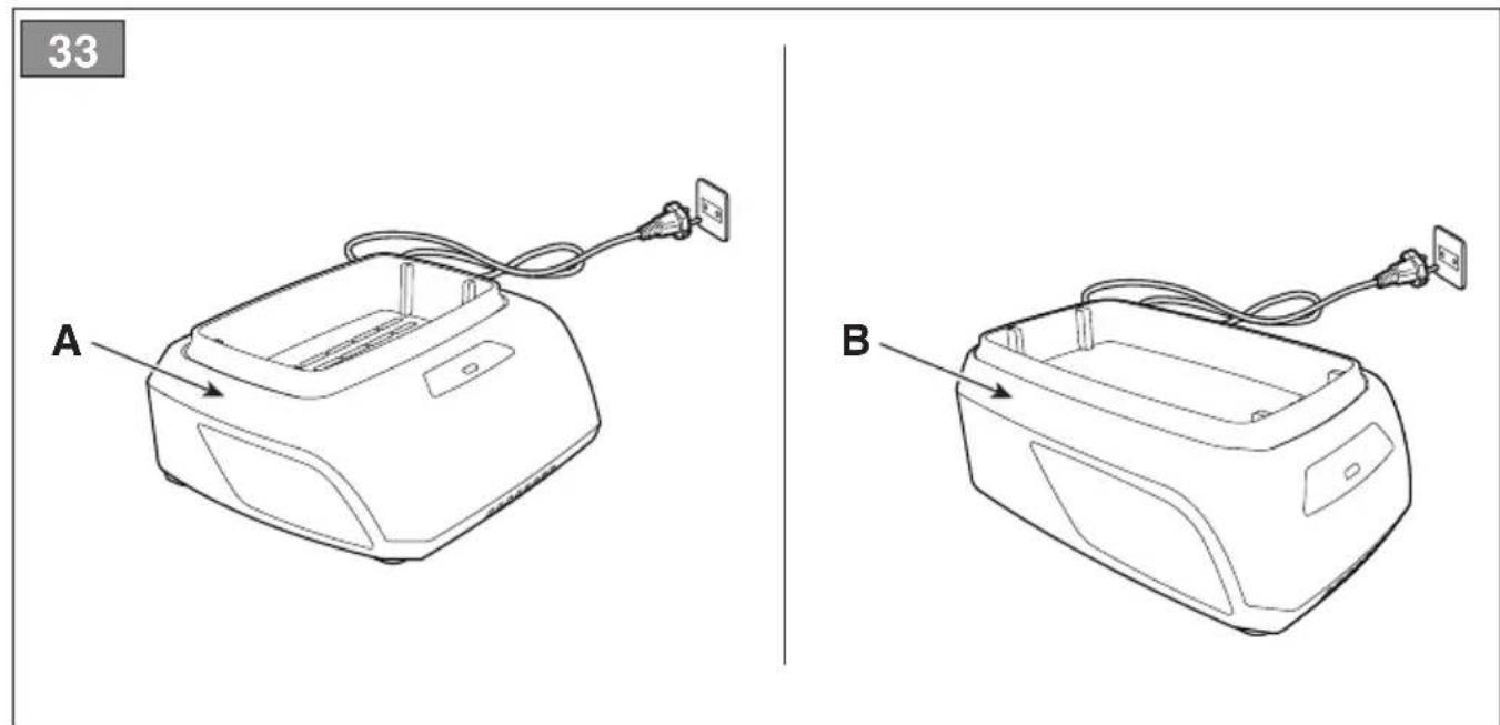
Device used to recharge the battery: fast (Fig. 33.A), standard (Fig. 33.B).
15.3 BATTERY BACKPACK
The device is used to place the two batteries and provides the electrical power required for the operation of the machine. It is provided with a cable used for the connection to the machine (Fig. 1.O) and with a selector (Fig. 11.B) to select one of the two batteries (position "1" and "2") and "OFF".
15.4 BATTERY SIMULATOR
Device that, if inserted in the machine housing, allows the use of the battery backpack.
INDICE
1.1 KUIDAS JUHENDIT LUGEDA
5.3 GAASI OHUTUSNUPP
10. MANUTENTION ET TRANSPORT
7. PLĀNOTĀ TEHNISKĀ APKOPE
2.4 BESCHERMING VAN DE OMGEVING
7.4 MOEREN EN SCHROEVEN VOOR BEVESTIGING
- ORDINÆRT VEDLIKEHOLD 13
- EKSTRAORDINÆRT VEDLIKEHOLD 15
3. BLI KJENT MED MASKINEN
3.1 BESKRIVELSE AV MASKINEN OG BE-REGNET BRUK
Denne maskinen er et utstyr til hagen og nærmere bestemt en bærbar batteridrevet gresstrimmer/krattrydder.
7. ORDINÆRT VEDLIKEHOLD
7.1 GENERELT
8. EKSTRAORDINÆRT VEDLIKEHOLD
8.1 VEDLIKEHOLD AV KLIPPEINNRET-NINGEN
13. VEDLIKEHOLDSTABELL
6.1 CZYNNOŚCI WSTĘPNE
6.4 PRACOVNÁ ČINNOST
(Supply of Machinery (Safety) Regulations 2008, S.I. 2008 No. 1597, Annex II, part A)
- The company: ST. S.p.A. – Via del Lavoro, 6 – 31033 Castelfranco Veneto (TV) – Italy
- Hereby declares under its own responsibility that the machine:
portable brush cutter/lawn trimmer (grass cutting)
a) Homologation type: BC 700 Li 48, BC 700 D Li 48
c) Serial number: 22A••TRB000001 ÷ 99L••TRB999999
d) Engine: battery-operated
- Conforms to UK Regulations:
• S.I. 2008/1597 - Supply of Machinery (Safety) Regulations 2008
• S.I. 2001/1701 - Schedule 9 - Noise Emission in the Environment by Equipment for use Outdoors Regulations 2001
e) Notified body: N. 0359 Intertek Testing & Certification LTD
Academy Place, 1-9 Brook Street, Brentwood, Essex, CM14 5NQ
• S.I. 2016/1091 - Electromagnetic Compatibility Regulations 2016
• S.I. 2012/3032 - The Restriction of the Use of Certain Hazardous Substances in Electrical and Electronic Equipment Regulations 2012
- Reference to harmonised standards:
EN 62841-1:2015 + A11:2022
EN ISO 11806-1:2022
EN 60335-1:2012 + A15:2021
EN 50636-2-91:2014
EN 55014-1:2021
EN 55014-2:2021
g) Measured sound power level: 94,2 dB
h) Guaranteed sound power level: 96 dB
i) Cutting width: 38 cm
n) Person authorised to compile the technical file:
o) Castelfranco Veneto, 10/01/2024
ST. S.p.A.
Via del Lavoro, 6
31033 Castelfranco Veneto (TV) - Italia
CEO Stiga Group
Sean Robinson

UK Importer: STIGA LTD
Unit 8, Bluewater Estate Plympton,
Devon, PL7 4JH, England

| FR (Traduction de la notice originale)Déclaration CE de Conformité(Directive Machines 2006/42/CE, Annexe II, partie A)1. La Société2. Déclare sous sa propre responsabilité que la machine : Débroussailleuse/coupeherbe portatif / coupe du gazona) Type / Modèle de Basec) Série d) Moteur: à batterie3. Est conforme aux prescriptions des directives :e) Organisme de certification : Non applicable4. Renvoi aux Normes harmoniséesg) Niveau de puissance sonore mesuréh) Niveau de puissance sonore garantii) Largeur de coupen) Personne habilitée à établir le Dossier Technique :o) Lieu et Date | EN (Translation of the original instruction)EC Declaration of Conformity(Machine Directive 2006/42/EC, Annex II, part A)1. The Company2. Herby declares under its own responsibility that the machine: portable brush cutter/lawn trimmer / Grass cuttinga) Type / Base Modelc) Serial numberd) Motor: battery-operated3. Conforms to directive specifications:e) Certifying body: Not applicable4. Reference to harmonised Standardsg) Sound power level measuredh) Sound power level guaranteedi) Range of cutn) Person authorised to create the Technical Folder:o) Place and Date | DE (Übersetzung der Originalbetriebsanleitung)EG-Konformitätserklärung(Maschinenrichtlinie 2006/42/EG, Anhang II, Teil A)1. Die Gesellschaft2. Erklärt auf eigene Verantwortung, dass die Maschine: TragbarerFreischneider/Rasenmäher / Rasenschnitta) Typ / Basismodellc) Seriennummerd) Motor: Batterie3. Den Anforderungen der folgenden Richtlinien entspricht:e) Zertifizierungsstelle: unzutreffend4. Bezugnahme auf die harmonisierten Normeng) Gemessener Schallleistungspegelh) Garantierter Schallleistungspegeli) Schnittbreiten) Zur Verfassung der technischen Unterlagen befragte Person:o) Ort und Datum |
| NL (Vertaling van de oorspronkelijke gebruiksaanwijzing)EG-verklaring van overeenstemming (Richtlijn Machines 2006/42/CE, Bijlage II, deel A)1. Het bedrijf2. Verklaart onder zijn eigen verantwoordelijkheid dat de machine: Draagbare bosmaaier/trimmer / grasmaaiera) Type / Basismodelc) Serienummerd) Motor: : accu3. Voldoet aan de specificaties van de richtlijnen:e) Certificatie-instituut: Niet toepasbaar4. Verwijzing naar de Geharmoniseerde normeng) Gemeten niveau van geluidsvermogen h) Gegarandeerd niveau van geluidsvermogen i) Snijbreedten) Bevoegd persoon voor het opstellen van het Technisch Dossier o) Plaats en Datum | ES (Traducción del Manual Original)Declaración de Conformidad CE (Directiva Máquinas 2006/42/CE, Anexo II, parte A)1. La Empresa2. Declara bajo su propia responsabilidad que la máquina: : Desbrozadora/cortadora de pasto portátil / corte hierbaa) Tipo / Modelo Basec) Matrículad) Motor: batería3. Cumple con las especificaciones de las directivas:e) Ente certificador: No aplica4. Referencia a las Normas armonizadasg) Nivel de potencia sonora medidoh) Nivel de potencia sonora garantizadoi) Amplitud de corten) Persona autorizada a realizar el Manual Técnico:o) Lugar y Fecha | PT (Tradução do manual original)Declaração CE de Conformidade (Diretiva de Máquinas 2006/42/CE, Anexo II, parte A)1. A Empresa2. Declara sob a própria responsabilidade que a máquina: Roçadeira/aparador de relva portátil / corte da relvaa) Tipo / Modelo Basec) Matrículad) Motor: Bateria3. É conforme às especificações das diretivas:e) Órgão certificador: Não aplicável4. Referência às Normas harmonizadasg) Nivel medido de potência sonorah) Nivel garantido de potência sonorai) Amplitude de corten) Pessoa autorizada a elaborar o Caderno Técnicoo) Local e Data |
| EL (Μετάφραση του πρωτοτύπου των οδηγιών χρήσης)ΕΚ-Δήλωση συμμόρφωσης (Οδηγία Μηχανών 2006/42/CE, Παράρτημα II, μέρος A)1. Η Εταιρία2. Δηλώνει υπεύθυνα ότι η μηχανή: Φορητό θαμνοκοπτικό/χλοοκοπτικό μπαταρίας / κοπτή της χλόηςa) Τύπος / Βασικό Μοντέλοc) Αριθμός μητρώουd) Κινητήρας: μπαταρία3. Συμμορφώνεται με τις προδιαγραφές της οδηγίας:e) Οργανισμός πιστοποίησης: Δεν εφαρμόζεται4. Αναφορά στους Κανονισμούς εναρμόνισηςg) Στάθμη μετρησης ακουστικής ισχύοςh) Στάθμη εγγυημένης ακουστικής ισχύοςi) Εύρος κοπτήςn) Εξουσιοδοτημένο άτομο για την κατάρτιση του Τεχνικού Φυλλαδίου:o) Τόπος και Χρόνος | TR (Orijinal Talimatların Tercümesi)AT Uygunluk Beyani(2006/42/CE Makine Direktifi, Ek II, bölüm A)1. Şirket2. Şahsi sorumluluğu altında aşağıdaki makinenin: taşınabilir çali biçme/kenar kesme makinesi /taşınabilir çim / çim kesimla) Tip / Standart modelc) Sicil numarasıd) Motor : batarya3. Aşağıdaki direktiflerin özelliklerine uygun olduğunu beyan etmektedir:e) Sertifikalandiran kurum: Uygulanamaz4. Harmonize standartlara atıfg) Ölçülen ses güç seviyesih) Garanti edilen ses güç seviyesi i) Kesim genişliğin) Teknik Dosyayi oluşturmaya yetkilikişi:o) Yer ve Tarih | MK (Превод на оригиналните упатства)Декларација за усогласеност со ЕУ (Директива за машини 2006/42/CE, Анекс II, дел A)1. Компанијата2. изјавува со целосна лична одговорност дека следната машина: Преносен поткаструвач/тревокосачка со напојување на батерија / косење треваа) Тип / основен моделс) етикетад) мотор: акумулатор3. Усогласено со спецификациите според директивите:д) тело за сертификација: Не се применува4. Референци за усогласени нормативи g) Акустички притисокh) измерено ниво на звучна мо́кностi) Ниво на гарантирана звучна мо́кностn) овластено лице за составување на Техничката брошурао) место и датум |
| NO (Oversettelse av orginalbruksanvisning)EF-Samsvarserklæring(Maskindirektiv 2006/42/EF, Vedlegg II, del A)1. Firmaet2. Erklærer på eget ansvar at maskinen: :Bærbar gresstrimmer/krattrydder /gressklippinga) Type / Modellc) Serienummerd) Motor: batteri3. Oppfyller kravene i direktivene:e) Sertifiseringsorgan: Ikke aktuelt4. Henvisning til harmoniserte standarderg) Målt lydeffektnivåh) Garantert lydeffektnivåi) Klippebredden) Person som har fullmakt til å utferdigeteknlsk dokumentasjon:o) Sted og dato | SV (Översättning av bruksanvisning i original)EG-försäkran om överensstämmelse (Maskindirektiv 2006/42//EG, bilaga II, dela)1. Företaget2. Försäkrar på eget ansvar att maskinen:Bärbar röjsåg/gräsklippare / gräsklippinga) Typ / Basmodellc) Serienummerd) Motor: batteri3. Överensstämmer med föreskrifterna i direktivete) Intygsorgan_Anmält organ: Intetillämpbar4. Referens till harmoniserade standarderg) Uppmätt ljudeffektnivåh) Garanterad ljudeffektnivåi) Skärbreddn) Auktoriserad person för upprättandet av den tekniska dokumentationen:o) Ort och datum | DA (Oversættelse af den originalebrugsanvisning)EF-overensstemmelseserklæring (Maskindirektiv 2006/42/EF, bilag II, del A)1. Firmaet2. Erklærer på eget ansvar, at maskinen:Bærbar, buskrydder/grästrimmer /klipning af græsseta) Type / Modelc) Serienummerd) Motor: batteri3. Er i overensstemmelse medspecifikationerne ifølge direktiverne:e) Certificeringsorgan: Ikke anvendelig4. Henvisning til harmoniserede standarderg) Målt lydeffektniveauh) Garanteret lydeffektniveaui) Klippebredden) Person, der har bemyndigelse til atudarbejde det tekniske dossier:o) Sted og dato |
| FI (Alkuperäisten ohjeiden käännös)EY-VAATIMUSTENMUKAISUUSVAKUUTUS(Konedirektivi 2006/42/EY, Liite II, osa A)1. Yritys2. Vakuuttaa omalla vastuullaan, että kone: Käsln kannateltava ralvaussaha/ruohonleikkuri / ruohonleikkuua) Tyyppl / Perusmalllc) Sarjanumerod) Moottori : akku3. On yhdenmukainen seuraaviendirektilvien asettamien vaatimustenkanssa:e) Sertifointiyritys : : Ei sovellettavissa4. Viittaus harmonisoituihinstandardeihing) Mitattu äänitehotasoh) Taattu äänitehotasoi) Leikkuuleveysn) Teknisten asiakirjojen laatimiseenvaltuutettu henkilö:o) Paikka ja päivämäärä | CS (Překlad původního návodu kpoužívání)ES – Prohlášení o shodě(Směrnice o Strojnic zařizenich 2006/42/ES, Příloha II, část A)1. Společnost2. Prohlášuje na vlastní odpovědnost, žestroj: Přenosný křovinořez/sekačka /sekačka na trávua) Typ / Základní modelc) Výrobní číslod) Motor: akumulátor3. Je ve shodě s nařízeními směrnic:e) Certifikační orgán: Nelze použít4. Odkazy na Harmonizované normyg) Naměřená úroveň akustického výkonuh) Zaručená úroveň akustického výkonui) Šířka řezánín) Osoba autorizovaná pro vytvořeníTechnického spisu:o) Misto a Datum | PL (Tłumaczenie instrukcji oryginalnej)Deklaracja zgodności WE(Dyretkywa maszynowa 2006/42/WE,Załącznik II, część A)1. Spółka2. Oświadcza na własną odpowiedzialność,że maszyna: Przenośna, podkaszarka/podcinarka/ kosiarka / cięcie trawya) Typ / Model podstawowyc) Numer seryjnyd) Silnik: akumulator3. Spełnia podstawowe wymoginastępujących Dyrektyw:e) Jednostka certyfikująca: Nie dotyczy4. Odniesienie do Norm zharmonizowanychg) Zmierzony poziom mocy akustycznejh) Gwarantowany poziom mocyakustyczneji) Szerokość cięcian) Osoba upoważniona do zredagowaniaDokumentacji technicznej:o) Miejscowość i data |
| HU (Eredeti használati utasitás fordítása)EK-megfelelőségi nyilatkozata(2006/42/EK gépirányelyv, ll. melléklet "A"rész)1. Alulírott Vállalat2. Felelősségének teljes tudatábankijelenti, hogy az alábbi gép: Hordozhatóbozótirtó/fünylró / fünyírása) Tipus / Alaptipusc) Gyártási számd) Motor: akkumulátor3. Megfelel az alábbi irányelvekelőírásainak:e) Tanúsitó szerv: Nem alkalmazható4. Hivatkozás a harmonizált szabványokrag) Mért zajteljesítmény színth) Garantált zajteljesítmény színti) Vágási szélességn) Müszaki Dosszlé szerkesztésérefelhatalmazott személy:o) Helye és ideje | RU (Перевод оригинальных инструкций)Декларация соответствия нормам EC(Директива о машинном оборудовании2006/42/EC, Приложение II, часть A)1. Предприятие2. Заявляет под собственнуюответственность, что машина: :Переносной кусторез/газонокосилка сбатарейным питанием / стрижка газонаa) Тип / Базовая модельc) Паспортd) Двигатель: батарея сгорания3. Соответствует требованиямследующих директив:e) Сертифицирующий орган:Непригодный4. Ссылки на гармонизированные нормыg) Измеренный уровень звуковоймощностиh) Гарантируемый уровень звуковоймощностиi) Амплитуда кошенияn) Лицо, уполномоченное на подготовкутехнической документации:o) Место и дата | HR (Prijevod originalnih uputa)EK Izjava o sukladnosti(Direktiva 2006/42/EZ o strojevima,dodatak II, dio A)1. Tvrtka:2. pod vlastitom odgovornošću izjavljujeda je stroj: Prijenosni čistač šikare/sišačtrave s napajanjem / košenje trava) Vrsta / Osnovni modelc) Matični brojd) Motor: baterija3. sukladan s temeljnim zahtjevimadirektiva:e) Certifikacijsko tijelo: Nije primjenjivo4. Primijenjene su slijedeće harmoniziranenorme:g) Izmjerena razlna zvučne snageh) Zajamčena razlna zvučne snagei) Širina rezanja) Osoba ovlaštena za pravljenje Tehničkedatoteke:o) Mjesto i datum |
| SL (Prevod izvirnih navodil)ES izjava o skladnosti(Direktiva 2006/42/ES), priloga II, del A)1. Družba2. pod lastno odgovornostjo izjavlja, da je stroj: Prenosna kosa/obrezovalnik trat / košnja travea) Tip / osnovni modelc) Serijska številkad) Motor: baterijaa) Skladen je z določili direktiv :e) Ustanova, ki izda potrdilo: Se ne uporabljaa) Sklicevanje na usklajene predpiseg) Izmerjen nivo zvočne močih) Zagotovljen nivo zvočne močii) Obseg košnjen) Oseba, pooblaščena za sestavotehnične knjižice:o) Kraj in datum | BS (Prijevod originalnih uputa)EZ izjava o sukladnosti(Direktiva o mašinama 2006/42/EZ, Prilog II, deo A)1. Firma2. Daje izjavu pod vlastitom odgovornošću da je mašina: trimer za travu / Košenje travea) Tip / Osnovni modelc) Serijski brojd) Motor: akumulator3. sukladna s osnovnim zahtjevimadirektive:e) Certifikaciono tijelo: Nije primjenjivo4. Pozivanje na usklađene normeg) Izmjereni nivo zvučne snageh) Garantovani nivo zvučne snagei) Širina košenjan) Osoba ovlaštena za izradu tehničkebrošure:o) Mjesto i datum | SK (Preklad pôvodného návodu napoužitie)ES vyhlásenie o zhode(Smernica o Strojných zariadeniach 2006/42/ES, Príloha II, čast' A)1. Spoločnosť2. Vyhlasuje na vlastnú zodpovednosť,že stroj: Prenosný krovinorez/kosačka / kosačka na trávu a) Typ / Základný modelc) Výrobné čislod) Motor: akumulátor3. Je v zhode s nariadeniami smerníc:e) Certifikačný orgán: Nepoužiteľné4. Odkaz na Harmonizované normyg) Nameraná úroveň akustického výkonuh) Zaručená úroveň akustického výkonui) Širka kosenian) Osoba autorizovaná na vytvorenie Technického spisu:o) Miesto a Dátum |
| RO (Traducerea manualului fabricantului)CE -Declaratie de Conformitate(Directiva Mašini 2006/42/CE, Anexa II, partea A)1. Societatea2. Declară pe propria răspundere că mašina: Mašlnă de tâlat arboret/mašlnă de tuns iarba portabilă / tâiat iarbaa) Tip / Model de bazác) Număr de serie d) Motor: baterie3. Este în conformitate cu specificațiilediretivelor:e) Organism de certificare: Nu se aplică4. Referință la Standardele armonizateg) Nivel de putere sonoră măsurath) Nivel de putere sonoră garantati) Lătjmea de tâieren) Persoană autorizată să întocmeascăDosarul Tehnico) Locul și Data | LT (Originalių instrukcijų vertimas)EB atitikties deklaracija(Mašinų direktyva 2006/42/CE, Priedas II, dalis A)1. Bendrovė2. Prisiima atsakomybę, kad įrenginys: :Rankinė krůmapjovė/žollapjovė / žolėspjovimasa) Tipas / Bazinis Modelisc) Serijos numerisd) Variklis: baterija3. Atitinka direktyvose pateiktas specifikacijas:e) Sertifikavimo įstaiga: Netaikoma4. Nuoroda į suderintas Normasg) Išmatuotas garso galios lyglish) Užtkrinamas garso galios lygisi) Pjovimo plotisn) Autorizuotas asmuo sudaryti TechninęDokumentaciją:o) Vieta Ir Data | LV (Instrukciju tulkojums no originálvalodas)EK atbilstības deklarācija(Direktīva 2006/42/EK par mašinām, pielikums II, daļa A)1. Uznēmums2. Uzņemoties par to pilnu atbildību, paziņo, ka mašina: Pārnesams krūmgriezis/plaujmašina ar barošanu / zāles plaušanaa) Tips / Bāzes modelisc) Sērijas numursd) Motors: akumulators3. Atbilst šădu direktīvu prasībām:e) Sertifikācijas iestāde: Nav piemērojams4. Atsauce uz harmonizētiem standartiemg) Izmērītais skaņas intensitātes līmenish) Garantētais skaņas intensitātes līmenisi) Plaušanas platumsn) Pilvarotais darbinieks, kas sagatavoja tehnisko dokumentāciju:o) Vieta un datums |
| SR (Prevod originalnih uputstval)EC deklaracija o usaglašenosti(Direktiva o mašinama 2006/42/EC, Prilog II, deo A)1. Prezuzeće2. Daje izjavu pod vlastitom odgovornošćuda je mašina: trimer za travu / košenjetravea) Tip / Osnovni modelc) Serijski brojd) Motor: akumulator3. u skladu s osnovnim zahtevimadirektiva:e) Sertifikaciono telo: Nije primenljivo4. Pozivanje na usklađene normeg) Izmereni nivo zvučne snageh) Garantovani nivo zvučne snagei) Širina košenjan) Osoba ovlaščena za sastavljanjetehničke brošureo) Mesto i datum | BG (Превод на оригиналните инструкции)EO декларация за съответствие(Директива Машини 2006/42/EO, Приложение II, част A)1. Дружеството2. На собствена отговорност декларира, че машината: : Преносим акумулаторен храсторез/тример / рязане на треваa) Вид / Базисен моделc) Сериен номерd) Motor: акумулатор3. Е в съответствие със спецификата на директивите:e) Сертифициращ орган: Не е приложимо4. Базирано на хармонизираните нормig) Ниво на измерена акустична мощностh) Гарантирано ниво на акустична мощностi) Широчина на косенеп) Лице, упълномощено да съставиТехническата Документация:o) Място и дата | ET (Algupārase kasutusjuhendi tõlge)EÜ vastavusdeklaratsioon(Masinadirektiiv 2006/42/EÜ, Lisa II, osa A)1. Firma2. Kinnitab omal vastutusel, et masin: võsalõikur/murutrimmer / murunitițaa) Tüüp / Põhimudelc) Matrikkeld) Mootor: aku3. Vastab direktiivide nõuetele:e) Kinnitav asutus: Ei ole kohaldatav4. Viide ühlustatud standarditeleg) Möõdetud helivõimsuse taseh) Garanteeritud helivõimsuse tasei) Löikelaiusn) Tehnilise Lehe autoriseeritud koostaja:o) Koht ja Kuupäev |
EN • The content and images in this User Manual were produced expressly for ST. S.p.A. and are protected by copyright – any unauthorised reproduction or modification to the document, either partially or in full, is prohibited.