USER MANUAL GT 500e STIGA
MANUAL DE INSTRUCTIUNI
3
4
5
6
7
natural_image
Technical illustration of a mechanical device with labeled parts and directional arrows (no text or symbols)
8
natural_image
Technical line drawing of a vehicle front panel with internal components and directional indicators (no text or symbols)
9
natural_image
Illustration of a person using a lawn power shaver to clean grass, with a wall marker and directional arrows (no text or symbols)
natural_image
Line drawing of a person wearing a full-body safety harness with directional arrows indicating movement or force (no text or symbols)
natural_image
Illustration of a person using a tool to spray or spray with motion arrows, no text or symbols present


natural_image
Line drawings of two electronic devices with ventilation grilles and mounting holes (no text or symbols)
[2] MAX supply voltage
[3] NOMINAL supply voltage
[4] Maximum tool rotation speed (cutting line head)
[5] Cutting width (cutting line head)
[6] Diameter of cutting line (max)
[7] Cutting means code
[8] Protection code
[9] Separable rod
[10] Weight without battery pack and without cutting means
[11] Dimensions
[12] Length
[13] Width
[14] Height
[15] Sound pressure level
[16] Uncertainty of measure
[17] Measured sound power level
[18] Guaranteed sound power level
[19] Vibrations
[20] Accessories available on request
[21] Battery pack
[22] Battery charger
[23] Battery backpack
[24] Battery simulator
(*) This battery can only be used with the battery backpack. Inserting the battery in the machine housing is prohibited.
a) NOTE: the declared total vibration value was measured using a normalised test method and can be used to conduct comparisons between one tool and another. The total vibration value can also be used for a preliminary exposure evaluation.
b) WARNING: the vibrations emitted during actual use of the tool can differ from the declared total value according to how the tool is used. Whilst working, therefore, it is necessary to adopt the following safety measures designed to protect the operator: wear protective gloves whilst working, use the machine for limited periods at a time and decrease the time during which the throttle control lever is pressed.
[1] ES - DATOS TÉCNICOŞ
[1] LT - TECHNINIAI DUOMENYS
[2] MAKS. maitinimo jtampa
[3] NOMINALI maitinimo jtampa
[24] Akumulatora simulators
- USO DELLA MACCHINA....12
6. USO DELLA MACCHINA
ВНИМАНИЕ! ОПАСНОСТ!
PAŽNJA! OPASNOST!
Držati na rastojanju od najmanje 15 m osobe ili domaće životinje za vrijeme upotrebe mašine!
Ne izlažite kiši (ili vlazi).

NEBEZPEČÍ VYMRŠTĚNÍ!
4.4 MONTÁŽ OCHRANNÉHO KRYTU ŽACÍHO ÚSTROJÍ
⚠️ Nasad'te si ochranné rukavice.
6.4 PRACOVNÍ ČINNOST
8.1 ÚDRŽBA ŽACÍHO ÚSTROJÍ
FARE FOR UDSLYNGNING!
3.3 TYPESKILT PÅ PRODUKTET
GEFAHR UMHERFLIEGENDER
- XEIPISTHPIA EΛΕΓΧΟΥ 10
ΠΡΟΣΟΧΗ! ΚΙΝΔΥΝΟΣ!
- GENERAL INFORMATION .... 1
- SAFETY REGULATIONS....2
- ABOUT THE MACHINE 6
3.1 Machine description and intended use...... 6
3.2 Safety signs....7
3.3 Product identification label 7
3.4 Main components....8
- ASSEMBLY 8
4.1 Assembly components....8
4.2 Rod installation....8
4.3 Fitting the FRONT hand grip 8
4.4 Fitting the guard on the cutting means..... 8
4.5 Fitting the indicator on the cutting limit ..... 9
4.6 FITTING OF THE BATTERY BACKPACK (if available)....9
- CONTROLS....9
5.1 Safety button (activation / deactivation) .....9
5.2 Throttle control lever....9
5.3 Throttle safety lever 10
- USING THE MACHINE 10
6.1 Preliminary operations.... 10
6.2 Safety checks.... 10
6.3 Start-up 11
6.4 Operation 11
6.5 Operating suggestions 12
6.6 Stop.... 12
6.7 After use.... 12
- ROUTINE MAINTENANCE....13
7.1 General Information.... 13
7.2 Battery.... 13
7.3 Cleaning the machine and the engine ..... 14
7.4 Nuts and bolts 14
- OCCASIONAL MAINTENANCE 14
8.1 Cutting means maintenance 14
8.2 Sharpening the wire cutting blade 15
- STORAGE....15
9.1 Storing.... 15
9.2 Storing the battery.... 15
-
HANDLING AND TRANSPORT 15
-
ASSISTANCE AND REPAIRS 15
- WARRANTY COVERAGE....16
- MAINTENANCE TABLE....16
- TROUBLESHOOTING....16
- ACCESSORIES ON REQUEST....18
15.1 Batteries.... 18
15.2 Battery charger.... 18
15.3 Battery backpack 18
15.4 Battery simulator 18
1.1 HOW TO READ THIS MANUAL
Some of the paragraphs in this manual contain particularly important information in terms of safety and operation, and are highlighted differently, according to the following criteria:
NOTE or IMPORTANT These give details or further information on what has been previously indicated and aim to prevent damage to the machine or cause other damage.
The symbol highlights danger. Failure to observe the warning can lead to possible personal and/or third party injury and/or damage.
The paragraphs highlighted in a dotted grey square indicate optional characteristics not available on all models documented in this manual. Check if the characteristics are available on this model.
Whenever reference is made to a position on the machine "front", "back", "left" or "right" hand side, this refers to the operator's working position.
1.2 REFERENCES
The figures in these instructions for use are numbered 1, 2, 3, etc.
Components shown in the figures are marked A, B, C, etc.
Reference to component C in figure 2 is indicated with the wording: "See fig. 2.C" or simply "(Fig. 2.C)".
The figures are provided by way of example. The actual pieces can differ from those illustrated in this document.
1.2.2 Titles
The manual is arranged in chapters and paragraphs. The title of paragraph '2.1 Training" is a sub-title of "2. Safety regulations". References to titles or paragraphs are marked with the abbreviation chap. or par. and the relevant number. Example: "chap. 2" or "para. 2.1."
2. SAFETY REGULATIONS
2.1 TRAINING
⚠️ Become familiar with the controls and the proper use of the machine. Learn how to stop the machine quickly. Failure to follow the warnings and instructions may result in fire and/or serious injury.
- Never allow the machine to be used by children or individuals with reduced physical, sensory or mental capabilities, or without experience and know-how, or individuals who do not have the necessary familiarity with the instructions. Local regulations may restrict the age of the operator.
- Never use the machine if the user is tired or unwell, or has taken medication, drugs, alcohol or substances that impair reflexes and concentration.
- Remember that the operator or user is responsible for accidents and unexpected events that can occur to other people or property. It is the user's responsibility to assess the potential risk of the area where work is to be carried out and to take all the necessary precautions to ensure his own safety and that of others, particularly on slopes or rough, slippery and unstable ground.
- If the machine is sold or lent to others, make sure that the operator looks over the user instructions contained in this manual.
2.2 PRELIMINARY OPERATIONS
Personal Protective Equipment (PPE)
- Always wear slim-fitting protective clothes with slash-proof protection, anti-vibration gloves, helmet, protective goggles, half-mask respirator, protective earplugs, cut resistant safety boots with non-slip soles.
- Use of hearing protections can reduce the ability to hear any warnings (shouting or alarms). Be careful of what occurs around you in the work area.
- Never wear scarves, shirts, necklaces, bracelets, loose flowing clothing, laces or ties or any hanging or flapping accessory that could catch in the machine or in any objects or materials in the work area.
- Tie your hair back if it is long.
Work / Machine Area
- Thoroughly inspect the entire work area and remove anything that could be thrown by the machine or damage the cutting means/rotating units (stones, branches, iron wire, bones, etc.).
2.3 DURING OPERATION
Work Area
-
Do not use the machine in environments that pose the risk of explosion, in the presence of flammable liquids, gases or powders. Power tools create sparks which may ignite the dust or fumes.
• Work only in daylight or with good artificial light in good visibility conditions.
-
Keep people, children and animals away from the work area. Children must be supervised by another adult.
- Check that there is nobody within 15 metres of the machine's range of operation or within 30 metres for heavier cutting.
- Avoid working with wet grass, in the rain and when there is a risk of a thunderstorm, especially lightening.
- Do not expose the machine to rain or wet environments. Water entering a power tool will increase the risk of electric shock.
- Where possible, avoid working on wet, slippery ground or on uneven or steep ground that does not guarantee stability for the operator.
- Pay careful attention to uneven ground (hills, dips), slopes, hidden hazards and obstacles that could limit visibility.
- Be very careful near ravines, ditches or embankments.
- Always work across the face of the slope and never up and down it, being very careful when changing direction, making sure the cutting means is always downstream.
- Look out for traffic when using the machine near the road.
Conduct
- When working, the machine must always be firmly held in both hands, keeping the power unit on the right of the body and the cutting group below the line of the belt. Do not excessively extend arms.
- Avoid body contact with earthed or grounded surfaces, such as pipes, radiators,
cookers and refrigerators. There is an increased risk of electric shock if your body is earthed or grounded.
- Always use caution and take on a firm and well-balanced position.
- Never run, always walk.
• Always keep hands and feet away from the cutting means, when starting and when using the machine.
- Attention: the cutting means will continue to rotate for a few seconds after disengagement or after you have switched off the motor.
- Be careful of flying debris coming from the cutting means.
- Be careful of avoiding violent collisions between the cutting means and foreign objects/obstacles. Kickback may occur if the cutting means comes into contact with an obstacle/object. This contact can cause a rapid jerk in the opposite direction, pushing the cutting means up and towards the operator. Kickback can cause the operator to lose control of the machine, leading to serious consequences. To avoid kickbacks, take all the appropriate precautions indicated below:
– Firmly hold the machine, with two hands, and place your body and arms in a position that allows you to resist kickback.
- Do not extend the arms too high and do not cut above waist height.
– Use only the cutting means specified by the manufacturer.
– Follow the manufacturer's instructions concerning cutting means maintenance.
- Beware of injuries caused by devices used to cut the line length.
⚠️ If something breaks or an accident occurs during work, turn off the motor immediately and move the machine away to prevent further damage; if an accident occurs with injuries or third parties are injured, carry out the first aid measures most suitable for the situation immediately and contact the medical authorities for any necessary health care. Carefully remove any debris which could cause damage or injury to persons or animals if ignored.
Prolonged exposure to vibrations can cause injuries and neurovascular disorders (also called "Raynaud's syndrome" or "white hand"), especially to people suffering from circulation disorders. The symptoms can regard the hands, wrists and fingers and are shown through loss of sensitivity, torpor, itching, pain and discolouring of or structural changes to the skin. These effects can be worsened by low ambient temperatures and/or by gripping the hand grips excessively tightly. If the symptoms occur, the length of time the machine is used must be reduced and a doctor consulted.
Restrictions of use
- Do not use the machine if you are unable to hold it with both hands or keep steady on your legs while working.
- Never assemble metal cutting means. The use of metal or rigid blades of any type with this machine is prohibited.
- Never use the machine with damaged, missing or incorrectly positioned guards.
- Don't use the machine if the attachments/tools are not installed in their seats.
- Never disengage, deactivate, remove or tamper with the safety systems/micro switches installed.
- Do not use the power tool if the switch does not turn it on and off. Any power tool that cannot be controlled with the switch is dangerous and must be repaired.
- Do not strain the machine too much and do not use a small machine for heavy-duty work; if you use the right machine, you will reduce the risk of hazards and improve the quality of your work.
Ensure regular maintenance and correct storage to maintain machine safety and high performance levels.
Maintenance
- Never use the machine with worn or damaged parts. Faulty or worn-out parts must always be replaced and never repaired.
- Be careful during adjustment of the machine to prevent entrapment of the fingers between moving parts of the cutting means and fixed parts of the machine.
The noise and vibration levels shown in these instructions are the maximum levels for use of the machine. The use of an unbalanced cutting element, the excessive speed of movement, or the absence of maintenance have a significant influence on noise emissions and vibrations. Consequently, it is necessary to take preventive steps to eliminate possible damage due to high levels of noise and stress from vibration; maintain the machine well, wear ear protection devices, and take breaks whilst working.
Storage
- To reduce fire risks, do not leave containers with debris inside a room.
2.5 RESIDUAL RISKS
Despite compliance with all safety prescriptions, some further hazards may remain:
– danger of injuries to fingers and hands if caught in the rotation of the cutting line;
– danger of injuries to feet if struck by the cutting line,
- stones and soil projections.
2.6 BATTERY / BATTERY CHARGER
IMPORTANT The following safety instructions are in addition to the safety requirements provided in the specific battery and battery charger manual delivered with this machine.
- Only use battery chargers recommended by the
manufacturer to recharge batteries. An inadequate battery charger may cause electric shock, overheating or corrosive liquid to leak from the battery.
- Use only batteries specifically designed for your power tool. The use of other batteries may cause injuries and fire risks.
- Make sure that the machine is switched off before inserting the battery. Inserting a battery in a machine which is switched on can cause a fire.
- Keep all unused batteries at a distance from paper clips, coins, keys, nails, screws or other small metal objects as contact with the same can cause short circuits. Short circuits between battery contacts can lead to explosion or fires.
- Do not use the battery charger in places where there are inflammable vapours, substances or on easily inflammable surfaces like paper, fabric, etc. During recharge, the battery charger becomes heated and may cause fire.
- When transporting batteries, do not allow the contacts ever to come into contact with each other and never use metal containers to transport them.
2.7 ENVIRONMENTAL PROTECTION
Protecting the environment must be a significant and top priority for machine use, to the benefit of civil co-habitation and of the environment that we live in.
- Avoid being an element of disturbance to the surrounding
area. Use this machine at reasonable times of the day only (not early morning or late evening when the noise could cause disturbance).
- Scrupulously comply with local regulations for the disposal of packaging, deteriorated parts or any elements with a strong environmental impact; this waste must not be disposed of with regular waste, but must be separated and taken to collection centres, which will recycle the materials.
- Comply with local regulations for the disposal of waste materials.
- When the machine is withdrawn from service, do not dispose of it in the environment, but take it to a waste disposal facility in accordance with the local regulations in force.
Do not throw electrical equipment away with domestic waste. According to European Directive 2012/19/EU on electrical and electronic equipment waste and its implementation, according to UK Regulation “The waste electrical and electronic equipment regulations 2013 (as amended)” and according to national regulations, old electrical equipment must be collected separately, for eco-compatible recycling. If electrical equipment is disposed of in a landfill or in the ground, the harmful substances can reach the water table and enter the food chain, damaging your health and well-being. For further information on the disposal of this product, contact
your dealer or a domestic waste collection service.
At the end of their working life, dispose of batteries safely in an eco-friendly manner. Batteries contain material classified as hazardous for you and the environment. They must be removed and disposed of separately at a facility that accepts lithium-ion batteries.

Separate waste collection of the products and packaging used allows the materials to be recycled and reused. Reuse of recycled materials help to prevent environmental pollution and reduces the demand for raw materials.
3. ABOUT THE MACHINE
3.1 MACHINE DESCRIPTION AND INTENDED USE
This machine is a garden tool and more precisely a battery-powered portable grass /grass edge trimmer.
The machine is essentially composed of a motor which, employing a transmission shaft, drives a cutting means (cutting line head).
The cutting means works on a surface that is approximately parallel to the ground (in case of use as grass trimmer) or approximately perpendicular to the ground (in case of use as grass edge trimmer.
The operator can operate the machine and use the main controls, always keeping a safe distance from the cutting means.
3.1.1 Intended use
This machine was designed and manufactured for:
– cutting grass and non woody vegetation (e.g. around the borders of flowerbeds, plants, walls, fences and small lawns);
– tidy up the cutting done using a mower;
– being used by one operator.
3.1.2 Improper use
Any other use that does not comply with the above, can be dangerous and cause damage to people and/or property. Examples of improper use may include, but are not limited to:
– using the machine for sweeping, tilting the cutting line head. The power of the motor could throw objects and small stones 15 metres or more, causing damage or injury to people;
– trimming hedges or other jobs in which the cutting means is not used at ground level;
– cutting and chopping trees, bushes and flowers;
– using the machine for cutting non-plant material;
– using the machine with the cutting means above the operator's belt level;
– using the machine in public gardens, parks, sports centres, on roadways, fields and woods;
– using cutting means other than those listed in the "Technical Data" table. Serious injury and wound hazard.
– using of the machine by more than one person.
IMPORTANT Improper use of the machine will void the warranty and relieves the Manufacturer of any liability, placing all responsibility for damage or injury, to him/herself or third parties, on the user.
3.1.3 Type of users
This machine is intended for use by consumers, i.e. non-professional operators. It is intended for "hobby-related activities".
3.2 SAFETY SIGNS
The machine has various symbols on it (fig. 2). Their function is to remind the operator of the correct conduct for use, with due care and caution.
Meanings of the symbols:

WARNING! DANGER!
Failure to use this machine correctly can be hazardous for oneself and others.
Read the owner's manual before using the machine

natural_image
Two black circular icons with white silhouette figures: one of a person wearing glasses, the other of a person wearing headphones (no text or symbols)
Anyone operating the machine under normal conditions for continuous daily use may be exposed to a noise level equal to or exceeding 85 dB (A). Use ear protection devices and goggles.
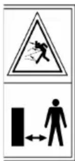
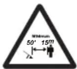
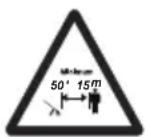
PROJECTION HAZARD!
Be careful of flying debris projected by the cutting means, that can cause serious injuries to persons or damage to things.
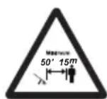
PROJECTION HAZARD!
People or pets must be kept at least 15m away when using the machine!

Do not leave the machine in the rain (or in damp conditions).
IMPORTANT Any damaged or illegible decals must be replaced. Order replacement decals from an Authorised Service Centre.
3.3 PRODUCT IDENTIFICATION LABEL
The product identification label provides the following data (fig. 1):
- Sound power level
- Conformity marking
- Year of manufacture
-
Type of machine
-
Serial number
- Name and address of Manufacturer
- Article code
Write the identification data of the machine in the specific space on the label on the back of the cover page.
IMPORTANT Quote the information on the product identification label whenever you contact an Authorised Service Centre.
IMPORTANT An example of the Declaration of Conformity is provided on the last pages of this manual.
3.4 MAIN COMPONENTS
The machine is composed of a series of main components that have the following functions (Fig.1):
A. Power unit: it drives the cutting means through a transmission shaft.
B. Rod: it connects the rear hand grip to the power unit.
C. Cutting means: the element designed to cut the vegetation.
- Cutting line head: nylon line cutting means.
D. Cutting means guard: it is a safety device which prevents objects drawn up by the cutting means from being hurled away from the machine.
E. Front hand grip: semi-circular shaped, it is used to handle the machine.
F. Rear hand grip: used to handle the machine and equipped with the main on/off/acceleration control buttons.
G. Battery (if it is not supplied with the machine, see chapter 15 "accessories on request"): device that supplies electric current to the tool; its specifications and regulations for use are described in a specific manual.
H. Battery charger (if it is not supplied with the machine, see chapter 15 "accessories on request"): device used to recharge the battery. Two battery charger models are available: H1 (fast battery charge); H2 (standard battery charge).
I. Battery backpack (attachment on request, par. 15.3): device in which the batteries are placed.
J. Connection cable: cable used to connect the machine to the battery backpack.
K. Battery simulator (attachment on request, par. 15.4): device that, if inserted in the machine housing, allows the use of the battery backpack.
4. ASSEMBLY
IMPORTANT The safety regulations to follow are described in chap. 2. Strictly comply with these instructions to avoid serious risks or hazards.
For storage and transport purposes, some components of the machine are not installed in the factory and have to be assembled after unpacking. Follow the instructions below.
⚠ Unpacking and completing the assembly should be done on a flat and stable surface, with enough space for machine handling and its packaging, always making use of suitable equipment. Do not use the machine until all the instructions provided in the “ASSEMBLY” section have been carried out.
4.1 ASSEMBLY COMPONENTS
The packaging includes assembly components.
4.1.1 Unpacking
- Carefully open the packaging, paying attention not to lose components.
- Consult the documentation in the box, including these instructions.
- Remove all the unassembled parts from the box.
- Remove the machine from the box.
- Dispose of the box and packaging in compliance with local regulations.
⚠️ Before assembling, make sure the battery is not inserted in its housing.
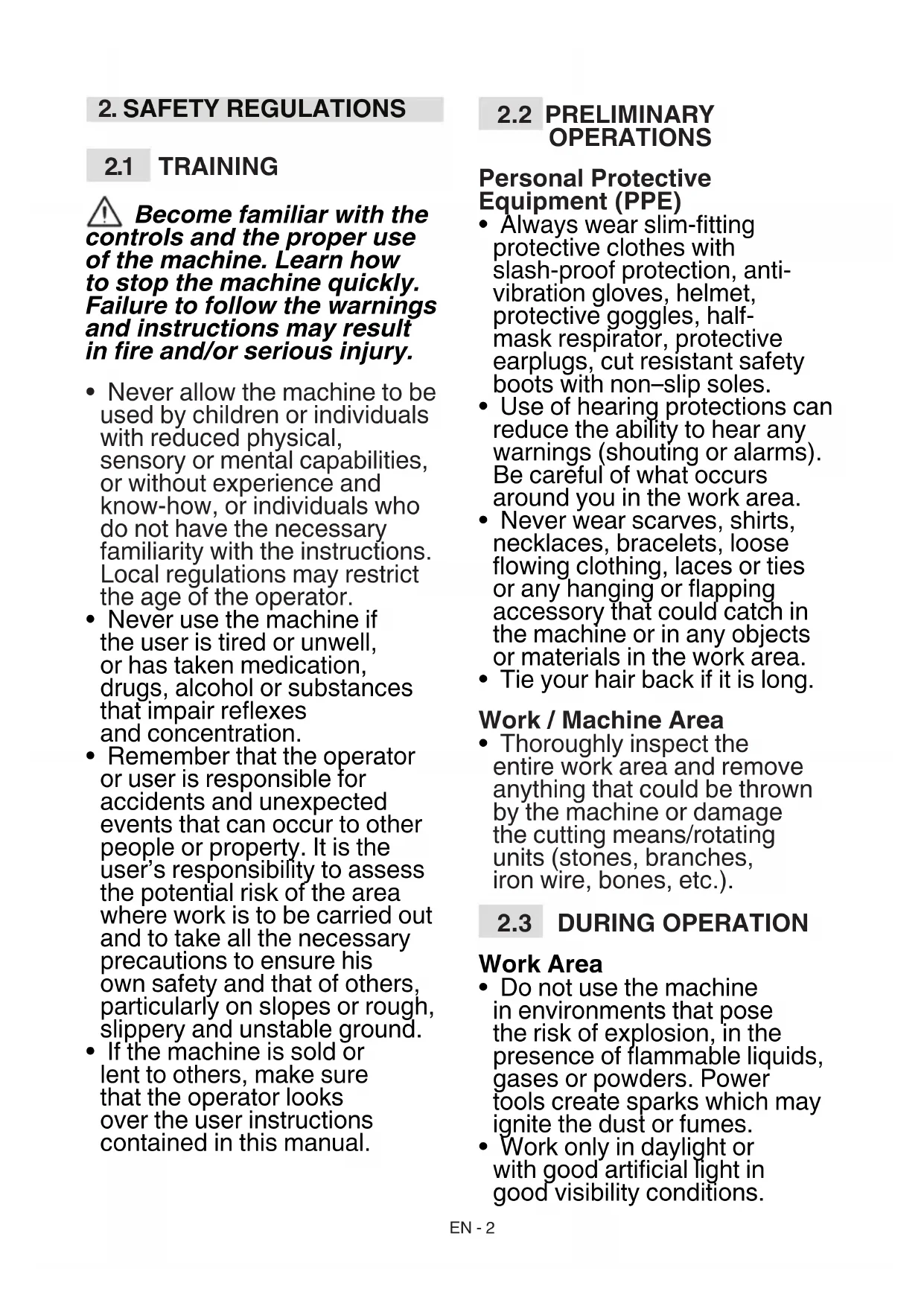
4.2 ROD INSTALLATION
- Insert and push the lower part of the rod (Fig. 3.A) in the upper part (Fig. 3.B) until your hear the stop pin that blocks it in the right position. The rod can be removed by pressing the button (Fig. 3.C).
The rod length is adjustable (par. 6.1.2).
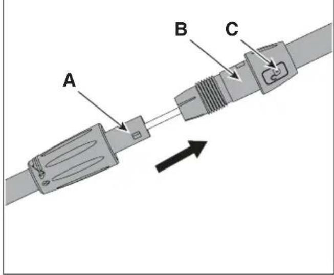
4.3 FITTING THE FRONT HAND GRIP
- Mount the front hand grip (Fig.4.A) on the support (Fig. 4.B), tighten it with the appropriate screw (Fig. 4.C) and lock the nut on the opposite side (Fig. 4.D).
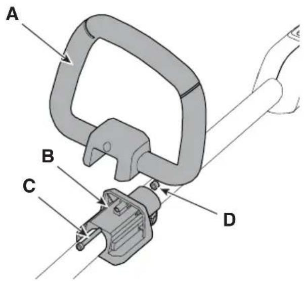
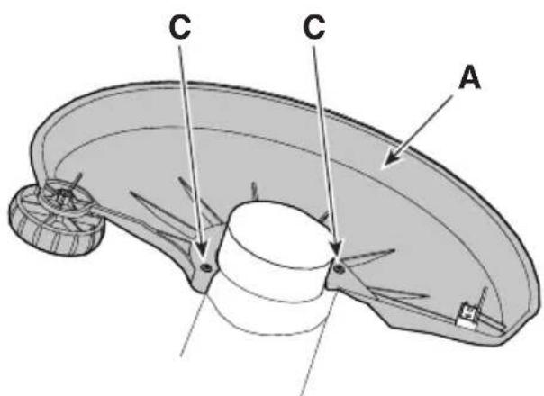
4.4 FITTING THE GUARD ON THE CUTTING MEANS

Wear protective gloves.
Every cutting means must be fitted with a specific guard, as indicated by the following directions in the Technical Data table.
- Place the guard (Fig. 5.A) on the holes on the power unit base (Fig. 5.B).
- Secure the guard (Fig. 5.A) fully tightening the screws (Fig. 5.C).
NOTE On the guard of the cutting means there is the following symbol:

It indicates the rotation direction of the cutting means.
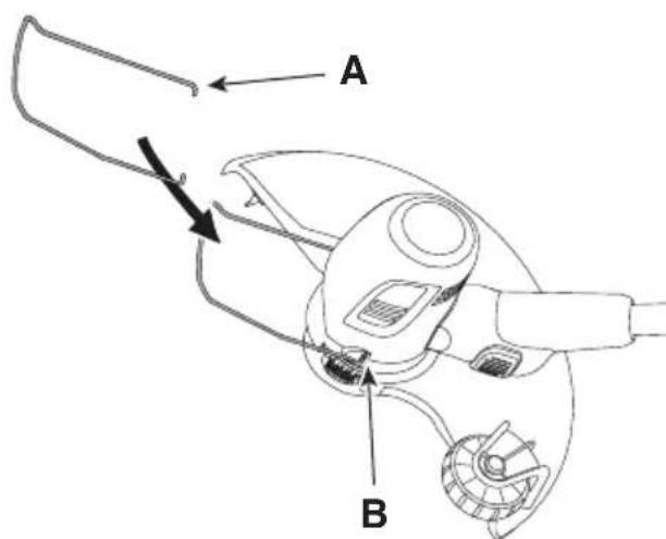
4.5 FITTING THE INDICATOR ON THE CUTTING LIMIT
– Insert and fasten the two ends of the cutting limit indicator (Fig. 6.A) in their respective holes on the power unit (Fig. 6.B).
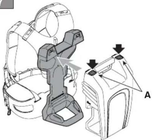
4.6 FITTING OF THE BATTERY BACKPACK (IF AVAILABLE)
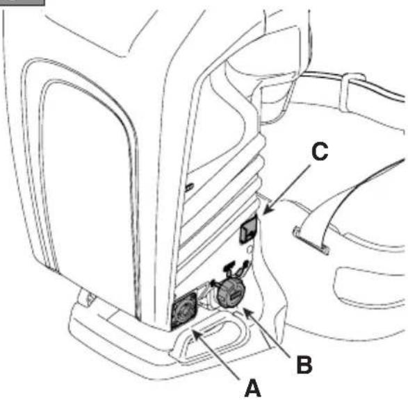
The battery backpack is delivered already assembled (Fig. 1.I) and can be released from the strap support (Fig. 7) and carried by hand. To release the battery backpack, press on the two upper buttons (Fig. 7.A). The battery compartments are located on both sides of the backpack (Fig. 8) The following can be found on the right side of the backpack:
- cable socket (Fig. 9.A)
- battery selector (Fig. 9.B)
- one USB port for charging other devices (e.g. mobile phones) (Fig. 9.C)
To avoid any loose cables, there are grooves on both sides and at the rear, in which the power cable can be inserted.
5. CONTROLS

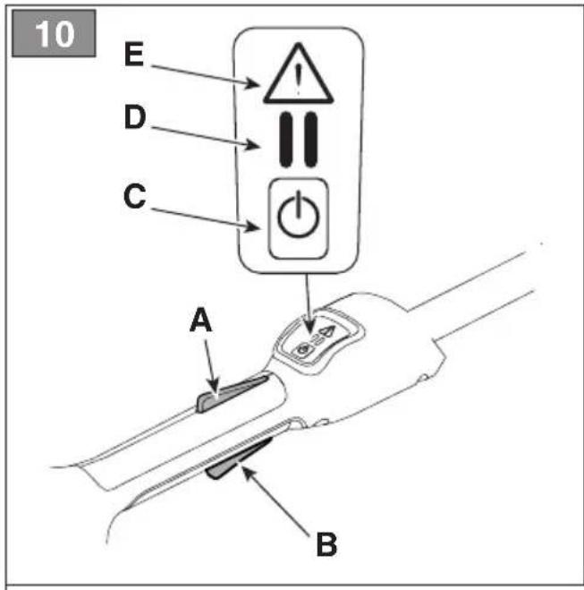
Press this button to activate and deactivate the machine's electrical circuit (Fig. 10.C).

One LED lit: the machine's electrical circuit is activated. The machine is ready for use. Both LEDs lit: the machine is operative (Fig. 10.D).
LEDs off: The electrical circuit is completely deactivated.
IMPORTANT Do not keep your finger on the button when moving the machine to avoid accidentally enabling the machine.

The "Warning" icon (Fig. 10.E) comes ON in the event of machine fault (refer to the troubleshooting table, par. 14).
5.2 THROTTLE CONTROL LEVER
It allows to start/stop the machine and simultaneously engages/disengages the cutting means.
The throttle safety lever (Fig. 10.A) can only be operated if the throttle safety lever is pressed at the same time (Fig. 10.B).
For machine start up:
– Simultaneously push the regulator control lever and safety lever.
Starting the machine causes the cutting means to start rotating at the same time.
The machine stops automatically as the throttle control lever is released.
5.3 THROTTLE SAFETY LEVER
The throttle safety lever (Fig. 10.B) allows the throttle control lever to be used (Fig. 10.A).
6. USING THE MACHINE
IMPORTANT The safety regulations to follow are described in chap. 2. Strictly comply with these instructions to avoid serious risks or hazards.
6.1 PRELIMINARY OPERATIONS
Before starting work it is necessary to carry out several checks and operations to ensure you can work efficiently and in maximum safety:
- make sure the battery is not inserted in its housing;
- place the machine in a stable horizontal position on the ground;
- adjust the machine from ergonomic and functional points of view in order to adapt it to the worker stature and to the type of work (par. 6.1.1 - par. 6.1.4);
- check the battery (par. 6.1.5).
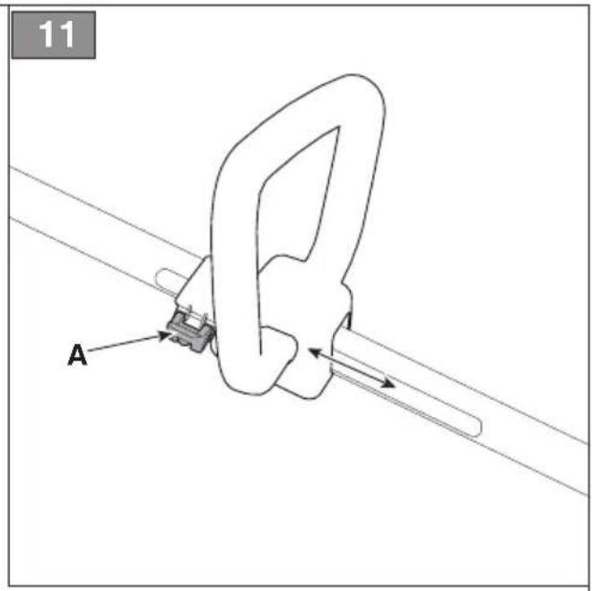
6.1.1 Regulating the front hand grip
- Slacken the clamp (Fig. 11.A);
- move the front hand grip into the most ergonomic position for the operator;
- tighten the clamp.
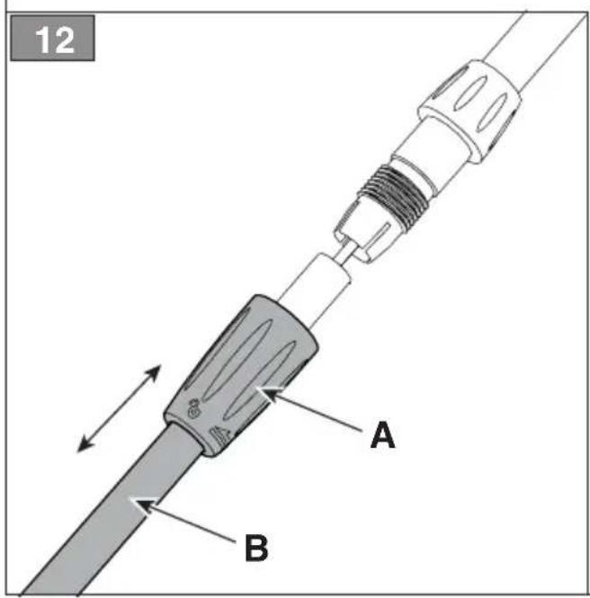
6.1.2 Adjusting the length of the rod
- Loosen the knob (Fig. 12.A) following the direction of the arrow - open padlock;
- pull or push the rod (Fig. 12.B) until it reaches the desired length;
- when the adjustment is complete, tighten the hand grip following the direction of the arrow - closed padlock.
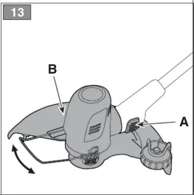
6.1.3 Aligning the cutting means
The cutting means orientation allows to switch from grass trimmer mode to grass edge trimmer mode, and vice versa, while working.
How to work in grass trimmer mode:
- Press the button (Fig. 13.A);
- Rotate the cutting means (Fig. 13.B) by 90^ , making sure it stays locked in position.
⚠ Perform this operation when the machine is turned off and the cutting means is still.
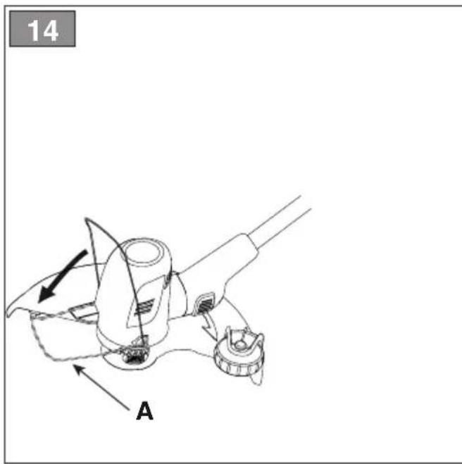
6.1.4 Adjusting the cutting limit indicator
- Rotate forwards the cutting limit indicator (Fig. 14.A) when working near trees, kerbs or fences, to avoid the impact with the cutting means.
6.1.5 Checking the battery
Before each use:
– check the battery charge status according to the instructions in the battery booklet.
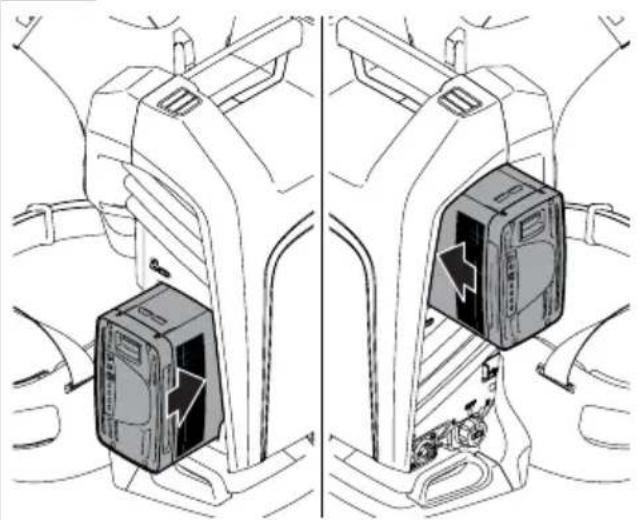
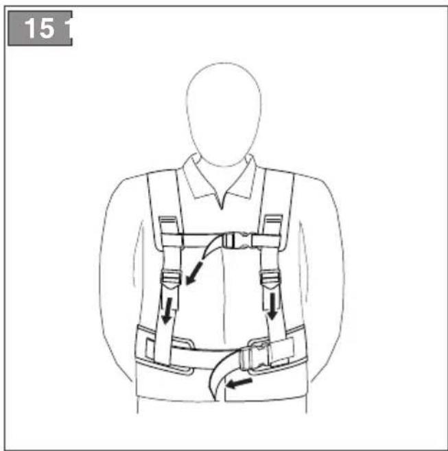
6.1.6 Use of the backpack (if available)
- Insert the battery in one of the compartments of the battery backpack (Fig. 8) and push it completely, until hearing the click that signals its locking in position, ensuring thus the electrical contact;
- Connect the cable to the backpack in the specific socket (Fig. 9.A) and rotate it until hearing the specific click that signals its locking in position, ensuring thus the electrical contact;
- adjust the straps and close the harness in the front (Fig. 15).
6.2 SAFETY CHECKS
Run the following safety checks and ensure that the results correspond to those outlined in the tables.
⚠️ Always carry out the safety checks before use.
6.2.1 General check
| Object Result | |
| Hand grips (Fig. 1.E) Clean | dry and fixed firmly to the machine. |
| Cutting means guard (Fig. 1.D) | Correctly and securely fit to the machine, not worn/ deteriorated or damaged. |
| Screws on the machine Correctly tightened (not loose) |
| Cutting means (Fig. 1.C) Clean | clean, not damaged or worn |
| Battery (Fig. 1.G) No damage to the casing, no liquid leakage |
| Cooling air ducts (par. 7.3) | Not clogged |
| Machine | No signs of damage or wear |
| Throttle control lever (Fig. 10.A), throttle safety lever (Fig. 10.B) | The levers must move freely and not be forced. |
| Test driving No abnormal vibrations.No abnormal sound |
6.2.2 Machine operating test
| Action Result | |
| 1. Fit the battery inside its housing (par. 7.2.3);2. Press the safety button (Fig. 10.C) | The LED (Fig. 10.D) must come ON (electrical circuit activated). |
| 1. Start the machine (para. 6.3);2. Simultaneously activate the throttle control lever (Fig. 10.A) and the throttle safety lever (Fig. 10.B);3. Release the throttle control lever (Fig. 10.A) and throttle safety lever (Fig. 10.B). | 1. The cutting means must not move.2. The cutting means should move.3. The levers should return automatically and rapidly to the neutral position and the cutting means should stop. |
| Press only the throttle control lever (Fig. 10.A). | The throttle control lever remains blocked. |
If any of the results fail to match the indications provided in the tables below, do not use the machine! Take it to a service centre to be checked and repaired if necessary.
6.3 START-UP
6.3.1 Start-up with battery
- Make sure the cutting means is not touching the ground or any other object;
- Insert the battery correctly in its housing (Fig. 16.B) (par. 7.2.3);
- Simultaneously activate the throttle control lever (Fig. 10.A) and throttle safety lever (Fig. 10.B).
NOTE At every start up new line is automatically released (par. 6.4.2).
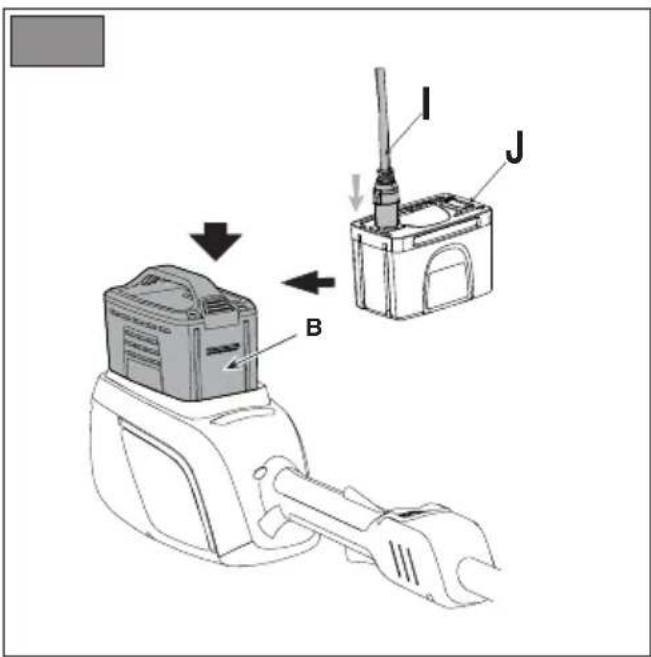
6.3.2 Start-up with battery simulator (if available)
- Make sure the cutting means is not touching the ground or any other object;
- Insert the battery simulator correctly in its housing on the machine (Fig.16.J);
- connect the connection cable to the battery simulator (Fig.16.I);
- select the battery using the selector (Fig. 9.B);
- Press the safety button (Fig. 10.C),
- engage the blade control lever (Fig. 10.A) and the safety switch simultaneously (Fig. 10.B).
6.4 OPERATION
NOTE Before tackling a mowing job for the first time, get to know the machine, learn the most suitable cutting techniques, grip the machine firmly and make the movements required by the job.
To use the machine proceed as follows: – always hold the machine firmly with two hands, using the cutting unit below the operator's belt level.
NOTE During use, the battery is protected against total drainage with a protective device that switches off the machine and stops it from working.
NOTE The battery power reserve (and therefore the mowable vegetation area before recharging is required) depends on various factors (par. 7.2.1).
NOTE After one minute of inactivity, if turned on, the machine will automatically switch off.
6.4.1 Work techniques
Use ONLY nylon lines. The use of metal lines, plastic coated metal lines and/or lines that are not suitable for the head can cause serious injuries and wounds.
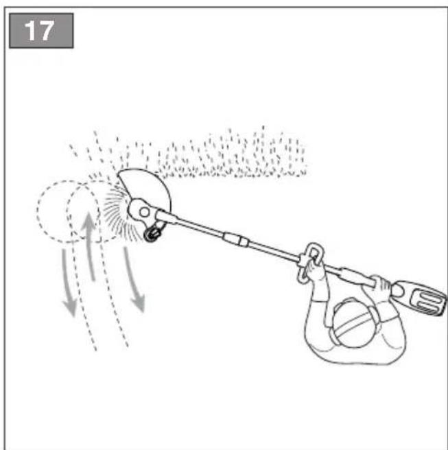
a. Cutting motion (Scything)
- Make sure the cutting means is in grass trimmer mode (par. 6.1.3);
– proceed at a regular pace, with a circular motion similar to a traditional scythe, without tilting the cutting line head during the operation (Fig. 17).
Start cutting at the correct height in a small area, so as to achieve a uniform cutting height keeping the cutting line head at a constant distance from the ground.
For heavier cutting it can be useful to tilt the cutting line head to the left by about 30^ .
Do not work in this way if there is the possibility of causing objects to be thrown, which could harm people, animals or cause damage.
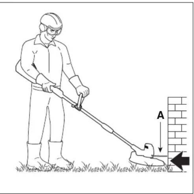
b. Precision cutting (Trimming)
Keep the machine slightly tilted so that the lower part of the cutting line head does not touch the ground and the cutting line is at the required point, always keeping the cutting means at a distance from the operator.
c. Cutting near fences/foundations
- Adjust the cutting limit indicator (if applicable, par. 6.1.4);
- move the cutting line head slowly towards fences, posts, rocks, walls, etc. without hitting them hard (Fig. 14).
If the line strikes a solid object it could break or become worn; if it gets tangled in a fence it could break suddenly. In any case, cutting around pavements, foundations, walls, etc. can cause greater wear than normal to the line.
d. Cutting around trees
- Adjust the cutting limit indicator (if applicable, par. 6.1.4);
- walk round the tree from left to right, approaching the trunks slowly so as not to strike the tree with the line and keeping the cutting line head tilted forward slightly.
Remember that the nylon line could lop off or damage small shrubs and that the impact of the nylon line against the trunk of bushes or trees with soft bark could seriously damage the plant.
6.4.2 Automatic line release
This machine is fitted with an automatic line release head.
To release new line:
- stop the machine (par. 6.6);
- wait for two seconds and restart the machine.
The cutting diameter is set to 30 cm.
Repeat the procedure until the line length reaches the line cutting knife (Fig. 18.A) that will cut any excess length.
6.5 OPERATING SUGGESTIONS
During use it is advisable to periodically remove weeds that wrap around the machine to avoid the motor overheating (Fig. 1.A), as well as under the cutting means guard (Fig. 1.D).
Proceed as follows:
- stop the machine (par. 6.6);
- remove the battery (par. 7.2.2);
- wear protective gloves;
– remove the caught-up grass with a screwdriver to allow the engine to be properly cooled.
6.6 STOP
To stop the machine:
- release the throttle control lever (Fig. 10.A);
- Wait until the cutting means stops.
When you have stopped the machine, it will take a few seconds for the cutting means to stop.
IMPORTANT Always stop the machine when moving between work areas.
6.7 AFTER USE
6.7.1 After use with the battery
- Remove the battery from its housing and recharge it (par 7.2.2).
- Allow the engine to cool before storing in an enclosed space.
- Clean (par. 7.3).
- Make sure there are no loose or damaged components. If necessary, replace the damaged components and tighten any screws and loose bolts or contact the authorised service centre.
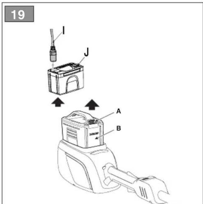
6.7.2 After use with battery simulator (if available)
- Move the battery backpack selector to "OFF" (Fig. 9.B);
- remove the battery simulator from the machine (Fig. 19.J);
- remove the battery backpack;
- disconnect the connection cable from the battery simulator (Fig.19.1) and from the backpack (fig. 9.A)
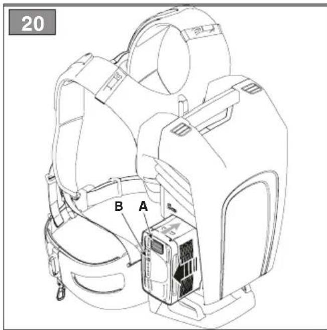
- remove the battery from the backpack (Fig. 20) and charge it (par. 7.2.2);
- allow the engine to cool before storing the machine in an enclosed space;
- Clean (para. 7.3);
- Make sure there are no loose or damaged components. If necessary, replace the damaged components and tighten any screws and loose bolts or contact the authorised service centre.
IMPORTANT Always remove the battery (par 7.2.2) whenever you leave the machine unused or unattended.
7. ROUTINE MAINTENANCE
IMPORTANT The safety regulations to follow are described in chap. 2. Strictly comply with these instructions to avoid serious risks or hazards.
Prior to carrying out any maintenance operation, you need to:
- Stop the machine;
- remove the battery from its housing and recharge it (par 7.2.2);
- allow the engine to cool before storing in an enclosed space;
- use suitable clothing, protective gloves and goggles;
- read the relevant instructions.
- The frequency and types of maintenance are summarised in the "Maintenance Table" (chapter 13). The table will help you maintain your machine's safety and performance. It summarises the main interventions to be made and the frequency applicable to each of them. Carry out the relevant task as soon as it is scheduled to be performed.
- The use of non-original parts and accessories could have negative effects on machine operation and safety. The manufacturer declines any responsibility for damage or injury caused by said products.
- Genuine spare parts are supplied by Authorised Assistance Centres and Dealers.
IMPORTANT Any maintenance and adjustment operations not described in this manual must be carried out by your dealer or Authorised Service Centre.
7.2 BATTERY
7.2.1 Battery power reserve
Battery power reserve (and therefore the cuttable vegetation area before recharging is required) mainly depends on:
a. Environmental factors, that cause higher energy requirements:
– cutting, high, wet vegetation;
b. operator behaviour that should be avoided:
– switching the machine on and off frequently whilst working;
- adopting a cutting technique that is unsuitable for the work to be performed (par. 6.4.1).
To optimise battery power reserve it is always recommended to:
• cut the grass when dry;
- use the most appropriate technique for the work to be performed (par. 6.4.1).
If the need arises to use the machine for sessions which exceed the capability of a standard battery, it is possible to:
• purchase a second standard battery to immediately replace the discharged battery, without compromising the continuity of operations;
• purchase a battery with an extended power reserve compared to the standard version (para. 15.1).
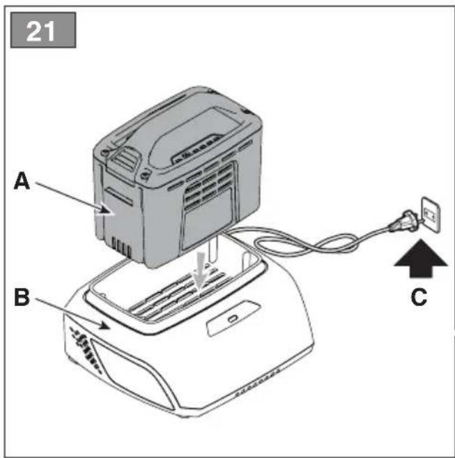
7.2.2 Battery removal and recharging
- Press the locking button located on the battery on the machine (Fig. 19.A) or on the backpack (Fig. 20.A) (if available);
-
remove the battery from the machine (Fig. 19.B) or from the battery backpack (Fig. 20.B) (if available);
-
Fit the battery (Fig. 21.A) in the battery charger compartment (Fig. 21.B);
- connect the battery charger (Fig. 21.C) to a power socket with the voltage indicated on the rating plate.
- fully charge the battery according to the instructions in the battery/battery charger booklet.
NOTE The battery is equipped with a guard that inhibits recharging if the environmental temperature is not between 0 and +45°C.
NOTE The battery can be recharged at any time, even partially, with no risk of damaging it.
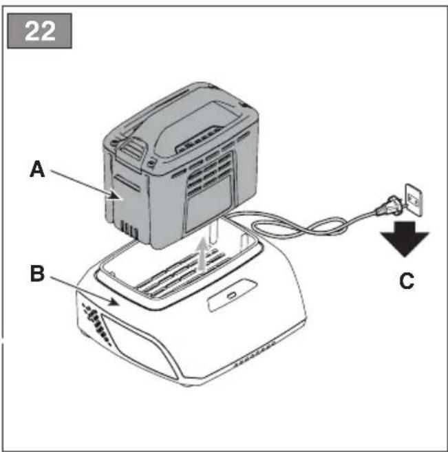
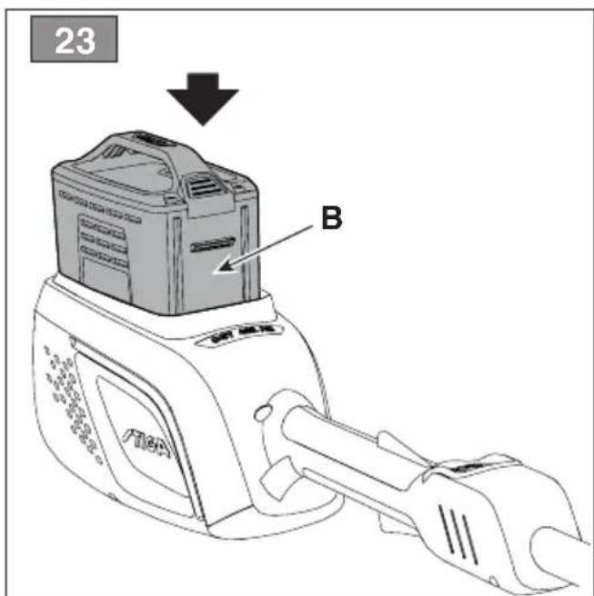
7.2.3 Refitting the battery on the machine
When recharging is completed:
- Remove the battery (Fig. 22.A) from its housing in the battery charger (Fig. 22.B) (do not continue recharging once recharging is completed);
- Disconnect the battery charger (fig. 22.C) from the mains power supply;
- Insert the battery in its housing on the machine (Fig. 23.B) or in one of the compartments of the battery backpack (Fig. 8) (if available);
- push it completely, until hearing the click that signals its locking in position, ensuring thus the electrical contact.
7.3 CLEANING THE MACHINE AND THE ENGINE
- Always clean the machine after use with a damp cloth dipped in neutral detergent.
- Remove all traces of humidity using a soft damp cloth. Humidity can generate risks of electric shocks.
- Do not use aggressive detergents or solvents to clean the plastic parts or hand grips.
- To reduce fire hazards, keep the machine and, in particular, the motor free of grass, leaves, or excessive grease.
- To avoid overheating and damage to the motor or the battery, always keep the cooling air vents clean and free of debris.
- Do not spray water onto the motor and electrical components and prevent them from getting wet.
7.4 NUTS AND BOLTS
- Keep all nuts, bolts and screws tight to be sure the equipment is in safe working condition.
- Check regularly that the handles are fixed firmly.
8. OCCASIONAL MAINTENANCE
Prior to carrying out any maintenance operation, you need to:
- stop the machine;
- remove the battery from its housing and recharge it (par 7.2.2);
- allow the engine to cool before storing in an enclosed space;
- use suitable clothing, protective gloves and goggles;
- read the relevant instructions.
Warning! Risk of injuries due to dangerous moving parts!
8.1 CUTTING MEANS MAINTENANCE
Cutting means displaying the code indicated on the Technical Data table should only be used on this machine.
Given product evolution, the cutting means mentioned in the "Technical Data" table may be replaced in time with others having similar interchangeable and operating safety features.
Do not touch the cutting means until the battery has been removed and the cutting means is completely stationary.
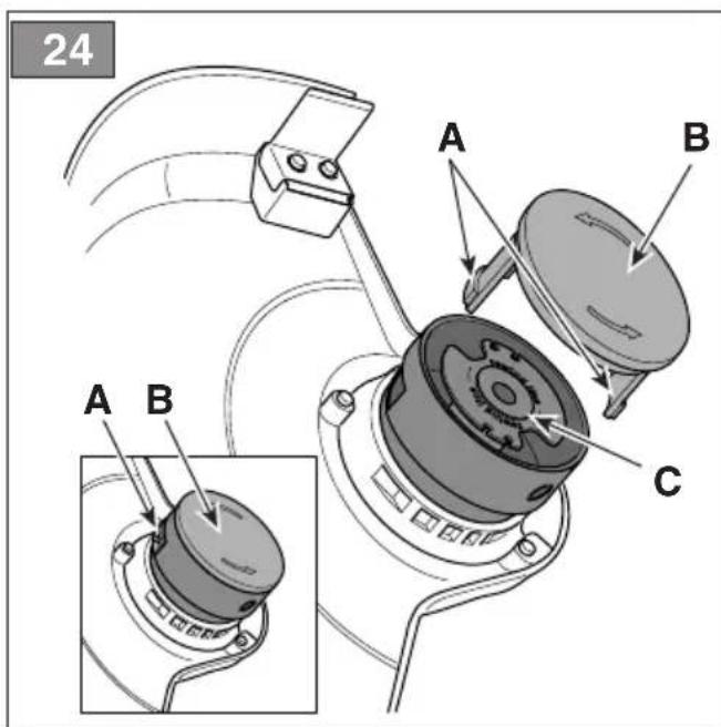
8.1.1 Replacing the reel of the cutting line head
- Press the two side tabs (Fig. 24.A) and remove the cover (Fig. 24.B);
- Remove the reel (Fig. 24.C);
- insert the new reel (Fig. 25.A), making sure the line extremity exits the head hole (Fig. 25.B);
- Refit the cover (Fig. 25.C) insert the two side tabs (Fig. 25.D) in the cutting line head openings (Fig. 25.E).
8.1.2 Replacing the cutting line head
- Remove the reel (par. 8.1.1);
- Remove the line left inside;
-
only use a line with diameter of 1.6 mm and cut 3 m of length.
-
align the lines that exit the two holes evenly;
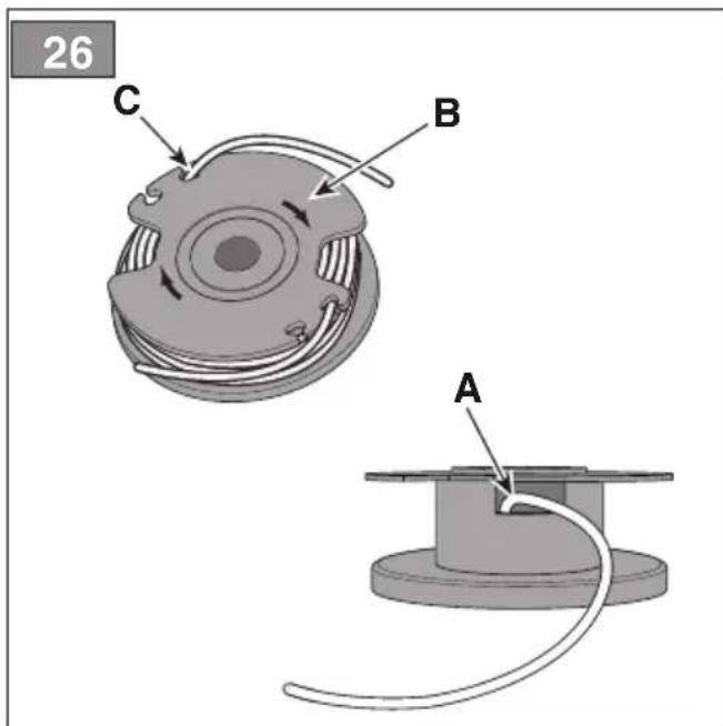
- insert the end of one line in the hole located inside the reel (Fig. 26.A) until it emerges from the opposite hole;
- wind the line in a clockwise direction as indicated by the arrows (Fig. 26.B) and allow about 15 cm to protrude from the reel;
- connect it with one of the anchorage sites (Fig. 26.C) on the reel;
- reposition the reel and reassemble the cover (cap 8.1.1).
8.2 SHARPENING THE WIRE CUTTING BLADE
- Remove the line cutting knife (Fig. 18.A) from the cutting means guard (Fig. 18.B) unscrewing the screws (Fig. 18.C);
- Fix the line cutting knife in a vice and sharpen it using a flat file, being careful to retain the original cutting angle;
- Re-assemble the line cutting knife (Fig. 18.A) on the cutting means guard (Fig. 18.B).
9. STORAGE
IMPORTANT The safety regulations to follow are described in chap. 2. Strictly comply with these instructions to avoid serious risks or hazards.
9.1 STORING
When the machine is to be stored away:
- Remove the battery from its housing and recharge it (par 7.2.2);
- allow the engine to cool before storing in an enclosed space;
- Clean (para. 7.3);
-
Make sure there are no loose or damaged components. If necessary, replace any damaged components and tighten any screws and loose bolts or contact the authorised service centre;
-
Store the machine:
– in a dry place;
– protected from inclement weather;
– in a place out of children's reach;
– making sure that keys or tools used for maintenance are removed.
9.2 STORING THE BATTERY
The battery must be kept in a cool, shaded place without humidity.
NOTE If unused for any length of time, recharge the battery every two months to prolong its working life.
10. HANDLING AND TRANSPORT
Whenever the machine is to be handled or transported you must:
- stop the machine (par. 6.6);
– remove the battery from its housing and recharge it (par. 7.2.2);
- wear protective work gloves;
– only hold the machine using the hand grips and position the cutting means in the opposite direction to that used during operations.
When transporting the machine on a vehicle, always:
– position it so that it does not cause a hazard to anyone.
11. ASSISTANCE AND REPAIRS
This manual provides all the necessary information to run the machine and for correct basic maintenance operations which can be performed by the user. Any regulations and maintenance operations not described herein must be carried out by your Dealer or Authorised Service Centre, which have the necessary knowledge and equipment to ensure that the work is carried out correctly, maintaining the correct degree of safety and the original operating conditions of the machine. Any operations performed in unauthorised centres or by unqualified persons will totally invalidate the Warranty and all obligations and responsibilities of the Manufacturer.
- Only Authorised Service Centres can carry out guaranteed repairs and maintenance.
- The Authorised Service Centres only use genuine spare parts. Genuine spare parts and attachments have been designed specifically for machines.
- Non-genuine spare parts and accessories are not approved. Use of non-genuine spare parts and accessories cause the warranty to be voided.
- It is advisable to send your machine once a year to an Authorised Service Centre for servicing, assistance and safety device inspection.
12. WARRANTY COVERAGE
The warranty covers all material and manufacturing defects. The user must follow all the instructions provided in the accompanying documentation.
The warranty does not cover damage caused by:
The purchaser is protected by his or her own national legislation. The purchaser's rights under the national laws or his or her own country are not in any way restricted by this warranty.
13. MAINTENANCE TABLE
| Intervention Frequency Notes | | |
| MACHINE |
| Check all fasteners | Before each use para. | 7.4 |
| Safety checks/check controls | Before each use para. | 6.2 |
| Check the cutting means guard. | Before each use par. | 6.2.1 |
| Checking the cutting means | Before each use par. | 6.2.1 |
| Check the battery charge status | Before each use * | |
| Recharge the battery | After each use para. | 7.2.2* |
| Cleaning the machine and the engine | After each use para. | 7.3 |
| Checking for any damage to the machine. If necessary, contact the authorised service centre. | After each use - | |
* Refer to the battery/battery charger manual.
14. TROUBLESHOOTING
If problems persist after implementing the solution, contact your Dealer.
| PROBLEM PROBABLE CAUSE SOLUTION | |
| 1. The cutting means is stationary and the machine does not start when the throttle control lever and throttle safety lever are engaged | Battery is not inserted or is inserted incorrectly | Make sure that the battery is inserted correctly (para. 7.2.3) |
| Low battery Check the battery status and recharge if necessary (para. 7.2.2) |
| The separable rod was not fully or properly inserted in its housing | Make sure the separable rod was installed and correctly inserted (par. 4.2) |
| Defective throttle control lever/throttle safety lever | Do not use the machine. Immediately turn off the machine remove the battery and contact an authorised service centre. |
| Machine damaged Do not use the machine. Immediately turn off the machine remove the battery and contact an authorised service centre. |
| 2. Motor overheating | Grass trapped under the cutting means guard | Remove trapped grass (par. 6.5) |
| 3. Grass accumulates around the power unit housing and the cutting line head | Too high grass is being cut close to the ground | Cut tall grass with a sweeping motion to avoid build up. |
| PROBLEM PROBALE CAUSE SOLUTION | |
| 4. The line is not released when the automatic release is turned on | The line is stuck to itself Lubricate with silicone spray |
| Not enough line on the reel or reel empty | Replace the reel (chap. 8.1.1) or the line (chap. 8.1.2) |
| The line is worn and too short Release the line manually (chap. 6.4.2.) |
| The line is tangled on the reel or broken Remove the line from the reel and rewind it (chapter 8.1.2) |
| 5. The cutting means comes into contact with a foreign body. | - Turn off the machine, remove the battery and: - inspect for damage; - check for and tighten any loose parts; - have all replacements or repairs carried out by an authorised service centre. |
| 6. Excessive noise and/or vibration is experienced whilst working | Loose or damaged parts. Turn off the machine, remove the battery and: - inspect for damage; - check for and tighten any loose parts; - have all replacements or repairs carried out by an authorised service centre. |
| 7. The machine gives off smoke whilst working | Machine damaged Do not use the machine. Immediately turn off the machine remove the battery and contact an authorised service centre. |
| 8. Battery power reserve is low | Severe working conditions requiring greater current absorption | Optimise operations (para. 7.2.1) |
| Battery is insufficient for operating requirements | Use a second battery or extended battery (par. 15.1) |
| Decrease in battery capacity Purchase a new battery | Check it is correctly inserted (par. 7.2.3) |
| 9. The battery charger is not recharging the battery | Battery is not correctly inserted in the battery charger |
| Unsuitable environmental conditions Recharge the battery in places with suitable temperatures (see battery/battery charger instruction manual) |
| Dirty contacts Clean the contacts | |
| The battery charger is not energised | Check it is plugged in and the power socket is energised |
| Faulty battery charger Replace with an original spare part |
| - | If the problem persists, refer to the battery/battery charger manual |
| 10. The LED indicator (Fig. 10.E) remains ON in steady mode | Self-check failed | Do not use the machine. Immediately turn off the machine, remove the battery and contact a service centre. |
| 11. The LED indicator (Fig. 10.E) remains ON in flashing mode | Battery communication error | Do not use the machine. Immediately turn off the machine, remove the battery and contact a service centre. |
| Rotor blocked | Do not use the machine. Immediately turn off the machine, remove the battery and contact a service centre. |
| Current overload | Optimize machine usage. |
15. ACCESSORIES ON REQUEST
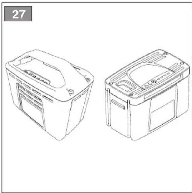
15.1 BATTERIES
Different capacity batteries are available to suit specific operating requirements (Fig. 27). The list of approved batteries for this machine can be found in the "Technical Data" table.
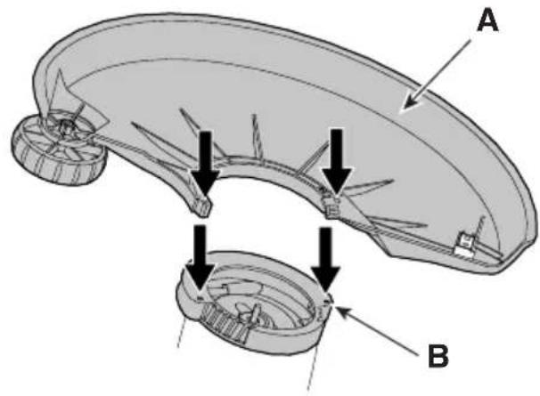
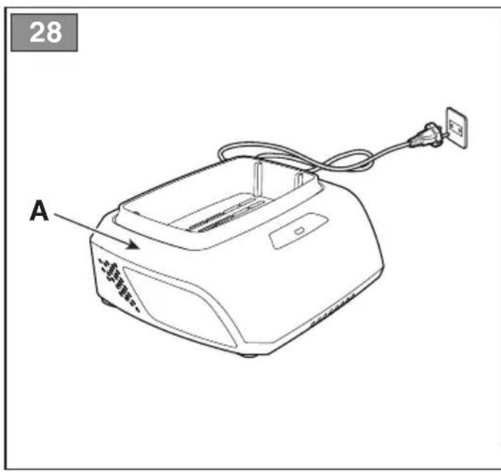
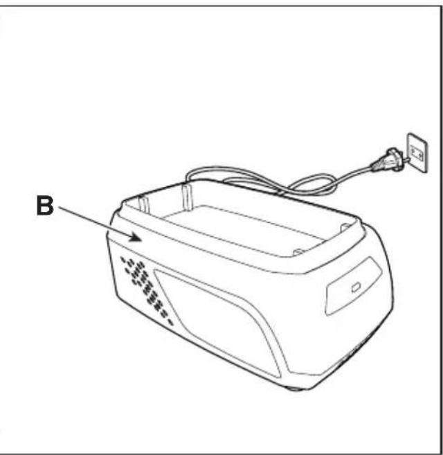
15.2 BATTERY CHARGER
Device used to recharge the battery: fast (Fig. 28.A), standard (Fig. 28.B).
15.3 BATTERY BACKPACK
The device is used to place the two batteries and provides the electrical power required for the operation of the machine. It is provided with a cable used for the connection to the machine (Fig. 1.I) and with a selector (Fig. 9.B) to select one of the two batteries (position "1" and "2") and "OFF".
15.4 BATTERY SIMULATOR
Device that, if inserted in the machine housing, allows the use of the battery backpack.
ÍNDICE
iPELIGRO DE
1.1 KUIDAS JUHENDIT LUGEDA
TÄHELEPANU! OHT!
EEMALEPAISKAMISE
5.3 GAASI OHUTUSNUPP
- SÄÄNNÖLLINEN HUOLTO....13
- YLIMAÄRAINEN HUOLTO....15
VAROITUS! VAARA!
SINKOUTUVIEN OSIEN VAARA!
ATTENTION ! DANGER !
DANGER DE PROJECTIONS !
10. MANUTENTION ET TRANSPORT
POZOR! OPASNOST!
Nepravilno rukovanje strojem može dovesti u opasnost samog korisnika i druge osobe.
Prije uporabe ovog stroja pročitajte priručnik s uputama.

OPASNOST OD ODBACIVANJA
PREDMETA! Pazite na moguće odbacivanje materijala prouzročeno reznim alatom, koje može prouzročiti teške ozljede osobama ili stvarima.

DÈMESIO! PAVOJUS!
- PLĀNOTĀ TEHNISKĀ APKOPE 14
UZMANİBU! BİSTAMI!
natural_image
Two black circular icons with white silhouette figures: one of a person wearing glasses, the other of a person wearing headphones (no text or symbols)
PRIEKŠMETU IZMEŠANAS
ПРЕДУПРЕДУВАЊЕ!
2.7 BESCHERMING VAN DE OMGEVING
GEVAAR VOOR WEGSPRINGENDE DELEN!
7.4 MOEREN EN SCHROEVEN VOOR BEVESTIGING
- GENERELT....1
- SIKKERHETSBESTEMMELSER....2
- BLI KJENT MED MASKINEN....7
- EKSTRAORDINÆRT VEDLIKEHOLD ...... 15
2.4 VEDLIKEHOLD, LAGRING
3. BLI KJENT MED MASKINEN
3.1 BESKRIVELSE AV MASKINEN OG BEREGNET BRUK
SPRUTFARE!
7. ORDINÆRT VEDLIKEHOLD
7.1 GENERELT
13. VEDLIKEHOLDSTABELL
ZAGROŻENIE WYRZUTEM!
6.1 CZYNNOŚCI WSTĘPNE
ATENTIE! PERICOL!
PERICOL DE PROIECTII!
UPOZORNENIE!
NEBEZPEČENSTVO
6.4 PRACOVNÁ ČINNOSŤ
POZOR! NEVARNOST!
INNEHÅLLSFÖRTECKNING
- ALLMÄN INFORMATION......1
- SÄKERHETSFÖRESKRIFTER....2
- LÄRA KÄNNA MASKINEN 7
(Supply of Machinery (Safety) Regulations 2008, S.I. 2008 No. 1597, Annex II, part A)
- The company: ST. S.p.A. – Via del Lavoro, 6 – 31033 Castelfranco Veneto (TV) – Italy
- Hereby declares under its own responsibility that the machine:
lawn/edge trimmer (grass cutting)
a) Homologation type: LT 500 Li 48
c) Serial number: 23A••TRB000001 ÷ 99L••TRB999999
d) Engine: battery-operated
- Conforms to UK Regulations:
• S.I. 2008/1597 - Supply of Machinery (Safety) Regulations 2008
- S.I. 2001/1701 - Schedule 9 - Noise Emission in the Environment by Equipment for use Outdoors Regulations
2001
e) Notified body:
• S.I. 2016/1091 - Electromagnetic Compatibility Regulations 2016
- S.I. 2012/3032 - The Restriction of the Use of Certain Hazardous Substances in Electrical and Electronic Equipment Regulations 2012
- Reference to harmonised standards:
EN 60335-1:2012 + A15:2021
EN 50636-2-91:2014
EN IEC 55014-1:2021
EN IEC 55014-2:2021
EN IEC 63000:2018
g) Measured sound power level: 91,9 dB
h) Guaranteed sound power level: 96 dB
i) Cutting width: 30 cm
n) Person authorised to compile the technical file: ST. S.p.A.
Via del Lavoro, 6
31033 Castelfranco Veneto (TV) - Italia
o) Castelfranco Veneto, 24/01/2024 CEO Stiga Group
Sean Robinson

UK Importer:
STIGA LTD
Unit 8, Bluewater Estate Plympton,
Devon, PL7 4JH, England

| FR (Traduction de la notice originale)Déclaration CE de Conformité(Directive Machines 2006/42/CE, Annexe II, partie A)1. La Société2. Déclare sous sa propre responsabilité que la machine : Coupe-herbe / Coupe-bordures - coupe du gazona) Type / Modèle de Basec) Série d) Moteur: accu3. Est conforme aux prescriptions des directives :e) Organisme de certification4. Renvoi aux Normes harmoniséesg) Niveau de puissance sonore mesuréh) Niveau de puissance sonore garanti j) Puissance nette installéen) Personne habilitée à établir le Dossier Technique :o) Lieu et Date | EN (Translation of the original instruction)EC Declaration of Conformity(Machine Directive 2006/42/EC, Annex II, part A)1. The Company2. Herby declares under its own responsibility that the machine: lawn/edge trimmer - grass cuttinga) Type / Base Modelc) Serial numberd) Engine: battery-operated3. Conforms to directive specifications:e) Certifying body4. Reference to harmonised Standardsg) Sound power level measuredh) Sound power level guaranteedj) Net power installedn) Person authorised to create the Technical Folder:o) Place and Date | DE (Übersetzung der Originalbetriebsanleitung)EG-Konformitätserklärung(Maschinenrichtlinie 2006/42/EG, Anhang II, Teil A)1. Die Gesellschaft2. Erklärt auf eigene Verantwortung, dass die Maschine:Rasentrimmer/Rasenkantenschneider, rasenschnitta) Typ / Basismodellc) Seriennummerd) Motor: Batterle3. Den Anforderungen der folgenden Richtlinien entspricht:e) Zertifizierungsstelle4. Bezugnahme auf die harmonisierten Normeng) Gemessener Schalleistungspegelh) Garantierter Schalleistungspegelj) Installierte Nettoleistungn) Zur Verfassung der technischen Unterlagen befugte Person:o) Ort und Datum |
| NL (Vertaling van de oorspronkelijke gebruiksaanwijzing)EG-verklaring van overeenstemming (Richtlijn Machines 2006/42/CE, Bijlage II, deel A)1. Het bedrijf2. Verklaart onder zijn eigen verantwoordelijkheid dat de machine: Graskantenrijder - Grasmaaiera) Type / Basismodelc) Serienummerd) Motor: accu3. Voldoet aan de specificaties van derichtlijnen:e) Certificatie-instituut4. Verwijzing naar de Geharmoniseerde normeng) Gemeten niveau van geluidsvermogenh) Gegarandeerd niveau van geluidsvermogenj) Netto geïnstalleerd vermogenn) Bevoegd persoon voor het opstellen van het Technisch Dossiero) Plaats en Datum | ES (Traducción del Manual Original)Declaración de Conformidad CE(Directiva Máquinas 2006/42/CE, Anexo II, parte A)1. La Empresa2. Declara bajo su propia responsabilidad que la máquina: Cortacésped/Cortabordes - corte hierbaa) Tipo / Modelo Basec) Matrículad) Motor: bateria3. Cumple con las especificaciones de las directivas:e) Ente certificador4. Referencia a las Normas armonizadasg) Nivel de potencia sonora medidoh) Nivel de potencia sonora garantizadoj) Potencia neta instaladan) Persona autorizada a realizar el Manual Técnico:o) Lugar y Fecha | PT (Tradução do manual original)Declaração CE de Conformidade(Diretiva de Máquinas 2006/42/CE, Anexo II, parte A)1. A Empresa2. Declara sob a própria responsabilidade que a máquina: : aparador de relva/cortadora de cantos - corte da relvaa) Tipo / Modelo Basec) Matrículad) Moto: Bateria3. É conforme às especificações das diretivas:e) Órgão certificador4. Referência às Normas harmonizadasg) Nivel medido de potência sonorah) Nivel garantido de potência sonoraj) Potência líquida instaladan) Pessoa autorizada a elaborar o Caderno Técnicoo) Local e Data |
| EL (Μετάφραση του πρωτοτύπου των οδηγιών χρήσης)ΕΚ-Δήλωση συμμόρφωσης (Οδηγία Μηχανών 2006/42/CE, Παράρτημα II, μέρος A)1. H Εταιρία2. Δηλώνει υπεύθυνα ότι η μηχανή:Χλοοκοπτικό/Κόφτης άκρων - κοπή της χλόηςa) Τύπος / Βασικό Μοντέλοc) Αριθμός μητρώουd) Κινητήρας: μπαταρία3. Συμμορφώνεται με τις προδιαγραφές της οδηγίας:e) Οργανισμός πιστοποίησης4. Αναφορά στους Κανονισμούς εναρμόνισηςg) Στάθμη μέτρησης ακουστικής ισχύοςh) Στάθμη εγγυημένης ακουστικής ισχύοςj) Καθαρή εγκαταστημένη ισχύςn) Εξουσιοδοτημένο άτομο για την κατάρτιση του Τεχνικού Φυλλαδίου:o) Τόπος και Χρόνος | TR (Orijinal Talimatların Tercümesi)AT Uygunluk Beyani(2006/42/CE Makine Direktifi, Ek II, bölüm A)1. Şirket2. ahsi sorumluluğu altında aşağıdaki makinenin: : beslemeli çim/kenar kesme – çim kesimia) Tip / Standart modelc) Sícil numarasıd) Motor: batarya3. Aşağıdaki direktifferin özelliklerine uygun olduğunu beyan etmektedir:e) Sertifikalandiran kurum4. Harmonize standartlara atifg) Ölçülen ses güç seviyesih) Garanti edilen ses güç sevlyesi j) Kurulu net güçn) Teknik Dosyayı oluşturmaya yetkilli kişl:o) Yer ve Tarih | MK (Превод на оригиналните упатства)Декларација за усогласеност со ЕУ(Директива за машини 2006/42/CE, Анекс II, дел A)1. Компанијата2. изјавува со целосна лична одговорност дека следната машина: :Тревокосачка со оператор на нозе / косење треваа) Тип / основен моделв) етикетаг) мотор: акумулатор3. Усогласено со спецификациите според директивите:д) тело за сертификација4. Референци за усогласени нормативие) Акустички притисокж) измерено ниво на звучна моёностз) Ниво на гарантирана звучна моёностн) obластено лице за составување на Техничката брошурао) место и датум |
| NO (Oversettelse av orginal bruksanvisning)EF- Samsvarserklæring (Maskindirektiv 2006/42/EF, Vedlegg II, del A)1. Firmaet2. Erklærer på eget ansvar at maskinen: trimmer/kantklipper, gressklippinga) Type / Modellc) Serienummerd) Motor: batteri3. Oppfyller kravene i direktivene:e) Sertifiseringsorgan4. Henvisning til harmoniserte standarderg) Målt lydeffektnivåh) Garantert lydeffektnivåj) Installert nettoeffektn) Person som har fullmakt til å utferdigteknisk dokumentasjon:o) Sted og dato | SV (Översättning av bruksanvisning i original)EG-försäkran om överensstämmelse (Maskindirektiv 2006/42//EG, bilaga II, de la)1. Företaget2. Försäkrar på eget ansvar att maskinen: gräsklippare/kantskärare, gräsklippingaa) Typ / Basmodellc) Serienummerd) Motor: batteri3. Överensstämmer med föreskrifterna i direktivetee) Intygsorgan_Anmält organ4. Referens till harmoniserade standarderg) Uppmätt ljudeffektnivåh) Garanterad ljudeffektnivåj) Installerad nettoeffektn) Auktoriserad person för upprättandet av den tekniska dokumentationen:o) Ort och datum | DA (Oversættelse af den originale brugsanvisning)EF-overensstemmelseserklæring (Maskindirektiv 2006/42/EF, bilag II, del A)1. Firmaet2. Erklærer på eget ansvar, at maskinen: græstrimmer/kantklipper, klipning af græsseta) Type / Modelc) Serienummerd) Motor: batteri3. Er i overensstemmelse med specifikationerne ifølge direktiverne:e) Certificeringsorgan4. Henvisning til harmoniserede standarderg) Målt lydeffektniveauh) Garanteret lydeffektniveauj) Installeret nettoeffektn) Person, der har bemyndigelse til at udarbejde det tekniske dossier:o) Sted og dato |
| FI (Alkuperäisten ohjeiden käännös)EY-VAATIMUSTENMUKAISUUSVAKUUTUS (Konedirektivi 2006/42/EY, Liite II, osa A)1. Yritys2. Vakuuttaa omalla vastuullaan, että kone: ruohonleikkuri/reunaleikkuri- ruohonleikkuua) Tyyppi / Perusmallic) Sarjanumerod) ) Moottori : akku3. On yhdenmukainen seuraavien direktiivien asettamien vaatimusten kanssa:e) Sertifointiyritys4. Viittaus harmonisoituihin standardeihing) Mitattu äänitehotasoh) Taattu äänitehotasoj) Asennettu nettoteholmastointikone-Niittokone / maamilmaus/haraus n) Teknisten asiakirjojenaatimiseen valtuutettu henkilö:o) Paikka ja päivämäärä | CS (Překlad původního návodu k používání)ES – Prohlášení o shodě (Směrnice o Strojních zařízeních 2006/42/ES, Přiloha II, část A)1. Společnost2. Prohlašuje na vlastní odpovědnost, že stroj: vyžinač/ořezávač- sekačka na trávuna trávu a) Typ / Základní modela) Typ / Základní modelc) Výrobní číslod) Motor: akumulátor3. Je ve shodě s nařízeními směrnice) Certifikační orgán4. Odkazy na Harmonizované normyg) Naměřená úroveň akustického výkonuh) Zaručená úroveň akustického výkonuj) Čistý instalovaný výkonn) Osoba autorizovaná pro vytvoření Technického spisu:o) Místo a Datum | PL (Tlumaczenie instrukcji oryginalnej)Deklaracja zgodności WE (Dyrektywa maszynowa 2006/42/WE, Załącznik II, część A)1. Spółka2. Oświadcza na własną odpowiedzialność,że maszyna: kosiarka/przycinarka-cięcietrawya) Typ / Model podstawowyc) Numer seryjnyd) Silnik: akumulator3. Spełnia podstawowe wymoginastępujących Dyrektyw:e) Jednostka certyfikująca4. Odniesienie do Norm zharmonizowanychg) Zmierzony poziom mocy akustycznejh) Gwarantowany poziom mocy akustycznejj) Moc zainstalowana netton) Osoba upoważniona do zredagowania Dokumentacji technicznej:o) Miejscowość i data |
| HU (Eredeti használati utasítás fordítása)EK-megfelelőségi nyilatkozata (2006/42/EK gépirányelv, II. melléklet "A" rész)1. Alulírott Vállalat2. Felelősségének teljes tudatában kijelenti,hogy az alábbi gép: fúnyíró/szegélynyíró-fúnyírása) Tipus / Alaptipusc) Gyártási számd) Motor: akkumulátor3. Megfelel az alábbi irányelvekelőírásainak:e) Tanúsító szerv4. Hivatkozás a harmonizált szabványokrag) Mért zajteljesítmény szinth) Garantált zajteljesítmény szintj) Nettó beépített teljesítményn) Műszaki Dosszié szerkesztésérefelhatalmazott személy:o) Helye és ideje | RU (Перевод оригинальных инструкций)Декларация соответствия нормам EC (Директива о машинном оборудовании 2006/42/EC, Приложение II, часть A)1. Предприятие2. Заявляет под собственнуюответственность, что машина: газонокосилка /триммер - стрижка газонаа) Тип / Базовая модельс) Паспортд) Двигатель: батарея3. Соответствует требованиям следующих директив:e) Сертифицирующий орган4. Ссылки на гармонизированные нормыg) Измеренный уровень звуковой мощностиh) Гарантируемый уровень звуковой мощностиj) Чистая установленная мощностьn) Лицо, уполномоченное на подготовку технической документации:o) Место и дата | HR (Prijevod originalnih uputa)EK Izjava o sukladnosti (Direktiva 2006/42/EZ o strojevima, dodatak II, dio A)1. Tvrtka:2. pod vlastitom odgovornošću izjavljuje da je stroj: trave/šišač travnih - košenje travea) Vrsta / Osnovni modelc) Matični brojd) Motor: baterija3. sukladan s temeljnim zahtjevimadirektiva:e) Certifikacijsko tijelo4. Primijenjene su slijedeće harmonizirane norme:g) Izmjerena razina zvučne snageh) Zajamčena razina zvučne snagej) Neto instalirana snagan) Osoba ovlaštena za pravljenje Tehničke datoteke:o) Mjesto i datum |
| SL (Prevod izvirnih navodil)ES izjava o skladnosti(Direktiva 2006/42/ES), priloga II, del A)1. Družba2. pod lastno odgovornostjo izjavlja, da je stroj: trat/tratnih robov, košnja travea) Tip / osnovni modelc) Serijska številkad) Motor: baterija3. Skladen je z določili direktiv :e) Ustanova, ki izda potrdilo4. Sklicevanje na usklajene predpiseg) Izmerjen nivo zvočne močih) Zagotovljen nivo zvočne močij) Neto instalirana močn) Oseba, pooblaščena za sestavo tehničneknjžice:o) Kraj in datum | BS (Prijevod originalnih uputa)EZ izjava o sukladnosti(Direktiva o mašinama 2006/42/EZ, Prilog II, deo A)1. Firma2. Daje izjavu pod vlastitom odgovornošćuda je mašina: trimer za travu/trimer makaze- Košenje trava) Tip / Osnovni modelc) Serijski brojd) Motor: akumulator3. sukladna s osnovnim zahtjevimadirektive:e) Certifikaciono tijelo4. Pozivanje na usklađene normeg) Izmjereni nivo zvučne snageh) Garantovani nivo zvučne snagej) Neto instalisana snagan) Osoba ovlaštena za izradu tehničkebrošure:o) Mjesto i datum | SK (Preklad pôvodného návodu na použitie)ES vyhlásenie o zhode(Smernica o Strojných zariadeniach 2006/42/ES, Priloha II, čast' A)1. Spoločnosť2. Vyhlasuje na vlastnú zodpovednosť, že stroj: vyžinač/orezávač okrajov -kosačka natrávua) Typ / Základný modelc) Vyrobné čislod) Motor: akumulátor3. Je v zhode s nariadeniami smerníc:e) Certifikačný orgán4. Odkaz na Harmonizované normyg) Nameraná úroveň akustického výkonuh) Zaručená úroveň akustického výkonuj) Čistý inštalovaný výkonn) Osoba autorizovaná na vytvorenieTechnického spisu:o) Miesto a Dátum |
| RO ( Traducerea manualului fabricantului)CE -Declaratie de Conformitate(Directiva Mașini 2006/42/CE, Anexa II, partea A)1. Societatea2. Declară pe propria răspundere cămașina: mașină de tuns iarba/trimmer - tăiatiarbaa) Tip / Model de bazăc) Număr de seried) Motor: baterie3. Este în conformitate cu specificațiiledirectivelor:e) Organism de certificare4. Referință la Standardele armonizateg) Nivel de putere sonoră măsurath) Nivel de putere sonoră garantaj) Putere netă instalataŋ) Persoană autorizată să întocmeascăDosarul Tehnico) Locul și Data | LT (Originalių instrukciju vertimas)EB atitikties deklaracija(Mašinų direktyva 2006/42/CE, Priedas II, dalis A)1. Bendrovė2. Prisiima atsakomybę, kad jrenginys: krūmapjovė/kraštų krūmapjovė, žolėspjovimasa) Tipas / Bazinis Modelisc) Serijos numerisd) Variklis: baterijaa) Sertifikavimo pateiktasspecifikacijas:e) Sertifikavimo jstaiga4. Nuoroda j suderintas Normasg) Išmatuotas garso galios lygish) Užtikrinamas garso galios lygisj) Instaliuota naudingoji galian) Autorizuotas asmuo sudaryti TechninęDokumentaciją:o) Vieta ir Data | LV (Instrukciju tulkojums no originálvalodas)EK atbilstības deklarācija(Direktīva 2006/42/EK par mašinām, pielikums II, daļa A)1. Uznēmums2. Uzņemoties par to pilnu atbildību, paziņo, ka mašina: trimeris/malu trimeris -zālesplaušanaa) Tips / Bāzes modelisc) Sērijas numurd) Motors: akumulators3. Atbilst šādu direktīvu prasībām:e) Sertifikācijas iestāde4. Atsauce uz harmonizētiem standartiemg) Izměrītais skaņas intensitātes līmenish) Garantētais skaņas intensitātes līmenisj) Uzstādītā neto jaudan) Pilnvarotais darbinieks, kas sagatavojatehnisko dokumentāciju:o) Vieta un datums |
| SR (Prevod originalnih uputstval)EC deklaracija o usaglašenosti(Direktiva o mašinama 2006/42/EC, Prilog II, deo A)1. Preduzeće2. Daje izjavu pod vlastitom odgovornošćuda je mašina: trimer za travu/trimer -košenje trava) Tip / Osnovni modelc) Serijski brojd) Motor: akumulator3. u skladu s osnovnim zahtevima direktiva:e) Sertifikaciono telo4. Pozivanje na usklađene normeg) Izmereni nivo zvučne snageh) Garantovani nivo zvučne snagej) Neto instalisana snagan) Osoba ovlašćena za sastavljanjetehničke brošureo) Mesto i datum | BG (Превод на оригиналните инструкции)EO декларация за съответствие(Директива Машини 2006/42/EO, Priложение II, част A)1. Дружеството2. На собствена отговорност декларира, че машината: тревен тример/тример захранвани - рязане на треваa) Вид / Базисен моделв) Сериен номерг) Мотор: акумулатор3. Е в съответствие със спецификата на директивите:д) Сертифициращ орган4. Базирано на хармонизираните нормиж) Ниво на измерена акустична мощности) Гарантирано ниво на акустична мощностк) Нетна инсталирана мощностр) Лице, упълномощено да съставиТехническата Документация:o) Място и дата | ET (Algupārase kasutusjuhendi tõlge)EÜ vastavusdeklaratsioon(Masinadirektiiv 2006/42/EÜ, Lisa II, osa A)1. Firma2. Kinnitab omal vastutusel, et masin: murulōikur/äärelōikur, murunitijaa) Tüüp / Põhimudelc) Matrikkeld) Mootor: aku3. Vastab direktiivide nõuetele:e) Kinnitav asutus4. Viide ühtlustatud standarditeleg) Möödetud helivõimsuse taseh) Garanteeritud helivõimsuse tasej) Installeeritud netovõimsusn) Tehnilise Lehe autoriseeritud koostaja:o) Koht ja Kuupäev |
EN • The content and images in this User Manual were produced expressly for ST. S.p.A. and are protected by copyright – any unauthorised reproduction or modification to the document, either partially or in full, is prohibited.