USER MANUAL GRL 650 CHVG Professional BOSCH
natural_image
Blank white image with a thin blue border (no text, symbols, or markings)


BOSCH
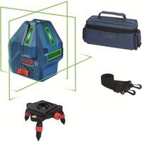
GRL 600 CHV | GRL 650 CHVG | RC 6 Professional
natural_image
Two identical blue and green radar or surveying equipment units with red and green labels, displayed against a solid blue background (no visible text or symbols on the devices themselves).
de Originalbetriebsanleitung
en Original Instructions
fr Notice originale
es Manual original
pt Manual original
It istruzione oralega
nl Oorspronkelijke gebruiksaanwijzing
da Original brugsanvising
sv Bruksanvlsning Original
no Original drifts instruks
No Original Intrinsic
fi Alkuparäicetohiret
1.2.10.1.1
en 1401016 oenviw xphnnc
tr Orijinal Isletme tal mat
pl instrukcja oryginaina
cs Původní návod k použivání
sk Pôvodný návod na použitie
hu Lredeti használati utasítás
English ...... Page 35
natural_image
3D mechanical component diagram with labeled part (17), no readable text or symbols beyond the number
GRL 600 CHV
GRL 650 CHVG

5
6
A
B
flowchart
graph TD
    A["Control Panel"] --> B["Directional Arrow 1"]
    A --> C["Directional Arrow 2"]
    A --> D["Directional Arrow 3"]
    A --> E["Directional Arrow 4"]
    A --> F["Directional Arrow 5"]
natural_image
Diagram of a surveying or radar setup with tripod-mounted sensors and measurement instruments (no text or symbols)
natural_image
Diagram of a surveying setup with tripod-mounted equipment and alignment wires, no visible text or symbols
natural_image
Interior view of a room with two cameras mounted on a tripod, showing perspective projection and mirror (no text or symbols)
natural_image
3D architectural rendering of a room with walls, windows, and structural beams (no text or symbols)
natural_image
Diagram of a 3D room setup with a camera on a tripod, showing structural beams and a floor block (no text or symbols)
(41)
LR 60
0 601 069 P..
(GRL 600 CHV)
LR 65 G
0 601 069 T..
(GRL 650 CHVG)
(50)
1 608 M00 05B
(GRL 600 CHV)
1 608 M00 05J
(GRL 650 CHVG)

(51)
1 608 M00 05C (GRL 600 CHV)
natural_image
Technical line drawing of a tripod-mounted device with labeled parts (43), no text or symbols present.
BT 300 HD
0 601 091 400
Inhaltsverzeichnis

natural_image
Diagram showing a device with a magnified view of its internal structure, including a circular component and a separate view (no text or symbols present)
natural_image
Diagram showing a vehicle with a car and a vertical dashed line, no text or symbols present
www.bosch-pt.com/serviceaddresses
Transport
Safety Instructions for Rotary Lasers and Remote Control ...... page 35
Product Description and Specifications ...... page 36
Intended Use......page 36
Product features ...... page 36
Rotary laser page 36
Rotary laser indicator elements......page 36
Remote control page 36
Accessories/replacement parts......page 36
Technical data ...... page 37
Assembly page 39
Measuring Tool Power Supply ...... page 39
Operation with Rechargeable Battery......page 39
Battery charge indicator......page 39
Recommendations for Optimal Handling of the Battery ...... page 39
Operation with Non-Rechargeable Batteries......page 39
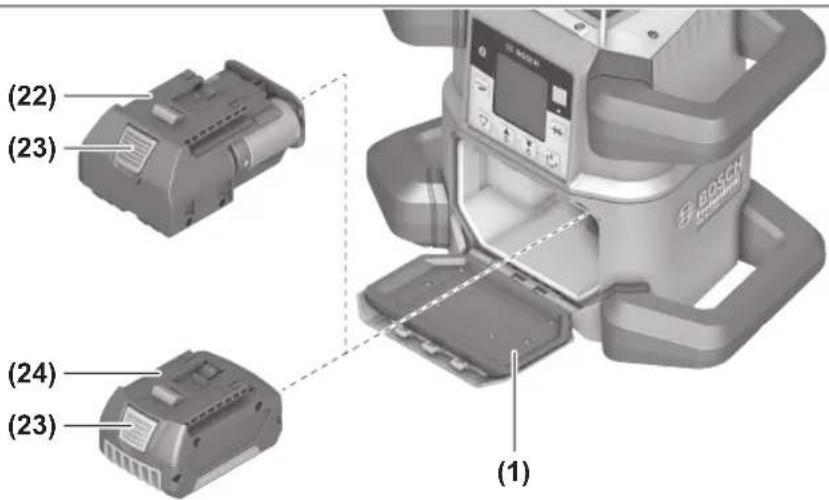
Changing the batteries/rechargeable battery (see figure A)...... page 39
Battery Charge Indicator ...... page 40
Remote control power supply ...... page 40
Operation...... page 40
Starting Operation of the remote control ...... page 40
Starting Operation of the rotary laser ...... page 40
Setting up the measuring tool ...... page 40
Operating the measuring tool......page 41
Switching On and Off......page 41
Establishing a connection to the remote control/laser receiver...... page 41
Remote control via Bosch Levelling Remote App...... page 42
Sleep mode......page 42
Locking the keyboard ...... page 42
Operating Modes ...... page 43
Alignment of X and Y-axis ...... page 43
Operating modes overview ...... page 43
Rotational operation......page 43
Line operation/point operation ...... page 43
Turning the line/point within the rotational plane ...... page 43
Turning the rotational plane when in the vertical position ...... page 43
Automatic downwards plumb point function in the vertical position....page 44
Automatic Levelling ...... page 44
Overview page 44
Position changes......page 44
Shock-warning function ...... page 44
Slope operation in the horizontal position...... page 45
Slope memory for slope operation in horizontal position (GRL 650 CHVG) ...... page 45
SlopeProtect......page 45
Manual operation ...... page 45
Manual operation in the horizontal position......page 46
Manual operation in the vertical position...... page 46
Functions......page 46
34 | English
CenterFind mode ...... page 46
CenterLock mode (GRL 650 CHVG) page 47
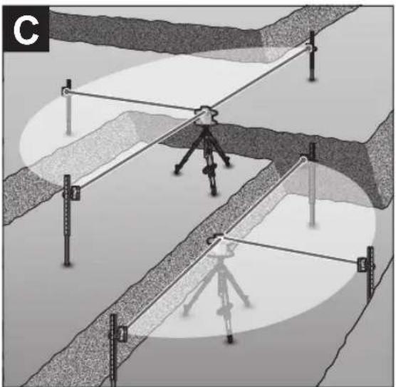
Mask mode (see figure C)...... page 47
Accuracy Check of the Measuring Tool......page 47
Influences on Accuracy ...... page 47
Checking the levelling accuracy in a horizontal position...... page 47
Checking the levelling accuracy in the vertical position ...... page 48
Calibrating the measuring tool....page 48
X-axis and Y-axis Calibration ...... page 48
Z-axis calibration ...... page 50
Working Advice......page 50
Working with the Laser Target Plate ...... page 51
Working with the Tripod (Accessory) ...... page 51
Laser Goggles (Accessory) ...... page 51
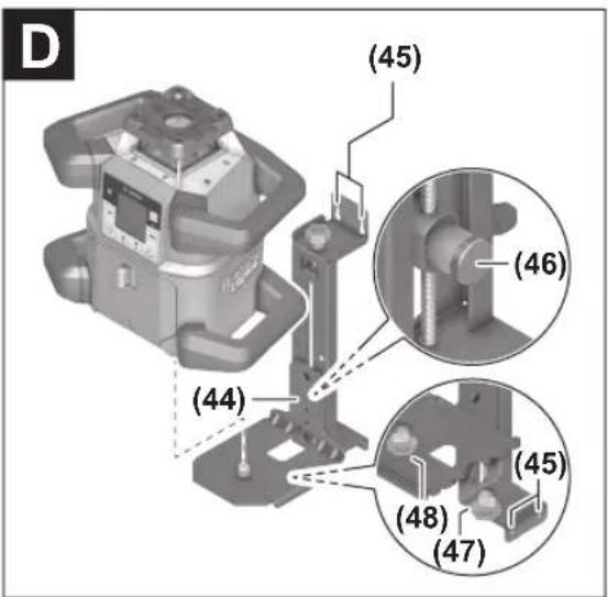
Working with a wall mount and alignment unit (see figure D)......page 51
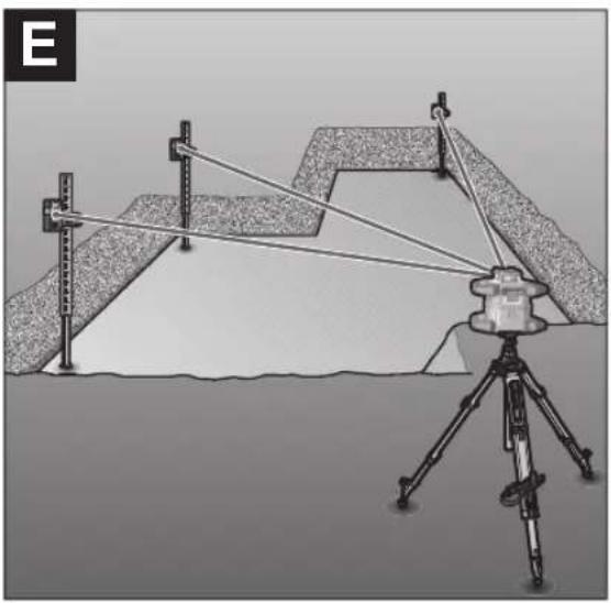
Working with the measuring rod (accessory) (see figure E) ...... page 51
Example applications......page 51
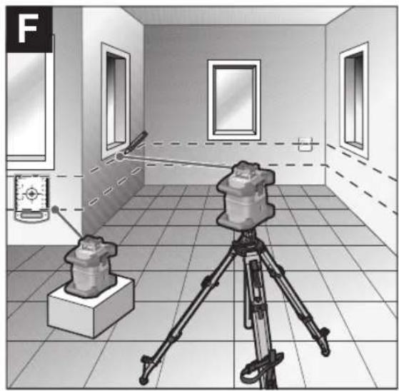
Projecting/checking heights (see figure F) ...... page 51
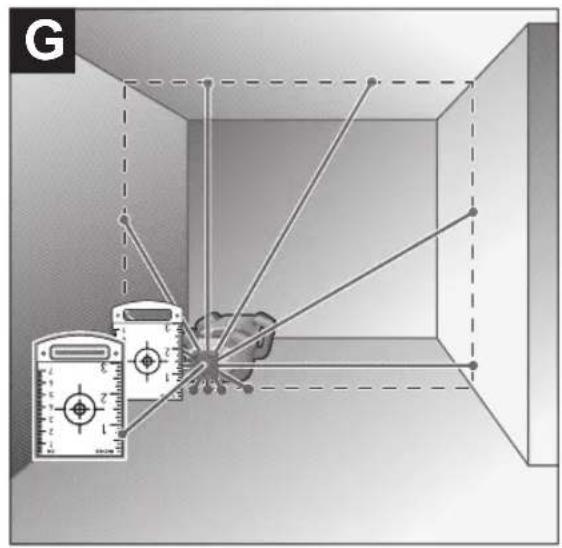
Parallel Alignment of Upwards Plumb Point/Projecting Right Angles (see figure G)...... page 51
Indicating a perpendicular/vertical plane (see figure G) ...... page 51
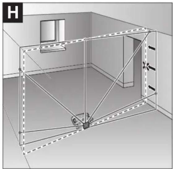
Aligning a Perpendicular/Vertical plane (see figure H)...... page 51
Working without the laser receiver....page 51
Working with the laser receiver (see figure E) ...... page 51
Working outdoors (see figure E) ...... page 52
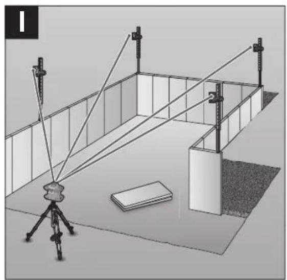
Setting up formwork (see figure I) ...... page 52
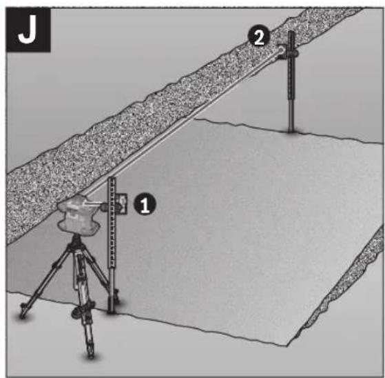
Checking slopes (see figure J) ...... page 52
Overview of status indicators......page 52
Overview of control options for the functions ...... page 53
Rectifying errors ...... page 54
Maintenance and Service.... page 55
Maintenance and Cleaning......page 55
After-Sales Service and Application Service ...... page 55
You can find further service addresses at:...... page 55
Transport......page 55
Disposal page 55
Only for EU countries:...... page 55
Battery packs/batteries: page 55
English
Safety Instructions for Rotary Lasers and Remote Control

All instructions must be read and observed in order to enable work to be carried out safely. The integrated safeguards may be compromised if these instructions are not observed. Never make warning signs unrecognisable.
STORE THESE INSTRUCTIONS IN A SAFE PLACE AND INCLUDE THEM WITH THE PRODUCT WHEN GIVING IT TO A THIRD PARTY.
▶ Warning! If operating or adjustment devices other than those specified here are used or other procedures are carried out, this can lead to dangerous exposure to radiation.
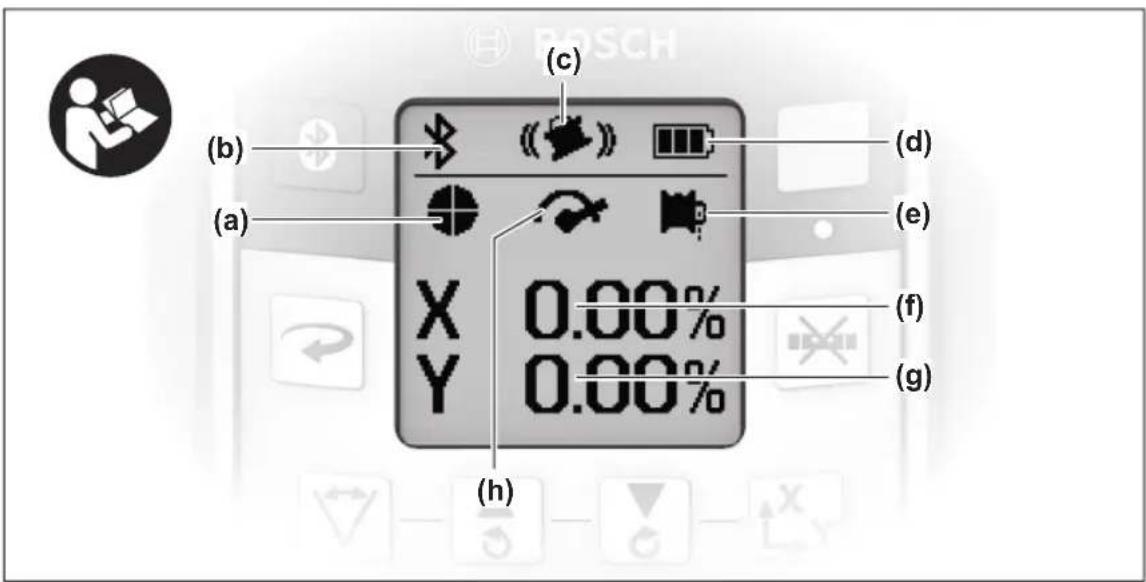
The measuring tool is delivered with a laser warning sign (marked in the illustration of the measuring tool on the graphics page).
▶ If the text of the laser warning label is not in your national language, stick the provided warning label in your national language over it before operating for the first time.

Do not direct the laser beam at persons or animals and do not stare into the direct or reflected laser beam yourself. You could blind somebody, cause accidents or damage your eyes.
▶ If laser radiation hits your eye, you must close your eyes and immediately turn your head away from the beam.
▶ Do not make any modifications to the laser equipment. The setting options described in these operating instructions can be used safely.
▶ Do not use the laser goggles (accessory) as protective goggles. The laser goggles make the laser beam easier to see; they do not protect you against laser radiation.
▶ Do not use the laser goggles (accessory) as sunglasses or while driving. The laser goggles do not provide full UV protection and impair your ability to see colours.
▶ Have your product serviced only by a qualified specialist using only original replacement parts. This will ensure that the safety of the product is maintained.
▶ Do not let children use the laser measuring tool unsupervised. They could unintentionally blind themselves or other persons.
▶ Do not operate in potentially explosive atmospheres, such as in the presence of flammable liquids, gases or dusts. Sparks may be produced, which can ignite dust or fumes.
▶ Do not use any optical instruments such as binoculars or magnifying glasses to view the radiation source. Doing so can damage your eyes.
▶ Do not open the rechargeable batteries or batteries. There is a risk of short-circuiting.
In case of damage and improper use of the battery, vapours may be emitted. The battery can set alight or explode. Ensure the area is well ventilated and seek medical attention should you experience any adverse effects. The vapours may irritate the respiratory system.
If used incorrectly or if the battery is damaged, flammable liquid may be ejected from the battery. Contact with this liquid should be avoided. If contact accidentally occurs, rinse off with water. If the liquid comes into contact with your eyes, seek additional medical attention. Liquid ejected from the battery may cause irritation or burns.
The battery can be damaged by pointed objects such as nails or screwdrivers or by force applied externally. An internal short circuit may occur, causing the battery to burn, smoke, explode or overheat.
When the battery is not in use, keep it away from paper clips, coins, keys, nails, screws or other small metal objects that could make a connection from one terminal to another. A short circuit between the battery terminals may cause burns or a fire.
▶ Only use the Bosch rechargeable battery with products from the manufacturer. This is the only way in which you can protect the battery against dangerous overload.
▶ Only charge the batteries using chargers recommended by the manufacturer. A charger that is suitable for one type of battery may pose a fire risk when used with a different battery.
Protect the rechargeable batteries against heat, e.g. against continuous sunlight, fire, dirt, water, and moisture. There is a risk of explosion and short circuit.
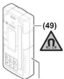
Keep the magnetic accessories away from implants and other medical devices, e.g. pacemakers or insulin pumps. The magnets in the accessories generate a field that can impair the function of implants and medical devices.
▶ Keep the magnetic accessories away from magnetic data storage media and magnetically-sensitive devices. The effect of the magnets in the accessories can lead to irreversible data loss.
Caution! When using the measuring tool with Bluetooth®, a fault may occur in other devices and systems, aeroplanes and medical devices (e.g. pacemakers, hearing aids). Also, damage to people and animals in the immediate vicinity cannot be completely excluded. Do not use the measuring tool with Bluetooth® in the vicinity of medical devices, petrol stations, chemical plants, areas with a potentially ex-
36 | English
plosive atmosphere and in blasting areas. Do not use the measuring tool with Bluetooth® on aeroplanes. Avoid using the product near your body for extended periods.
The Bluetooth® word mark and logos are registered trademarks owned by Bluetooth SIG, Inc. and any use of such marks by Robert Bosch Power Tools GmbH is under license.
Product Description and Specifications
Please observe the illustrations at the beginning of this operating manual.
Intended Use
Rotary laser
The measuring tool is intended for establishing and checking exactly horizontal height profiles, vertical lines, alignments and plumb points.
The measuring tool is suitable for indoor and outdoor use.
Remote control
The remote control is intended for controlling the Bosch rotary lasers via Bluetooth®.
The remote control is suitable for indoor and outdoor use.
Product features
The numbering of the product features refers to the illustration of the measuring tool and remote control on the graphics pages.
Rotary laser
(1) Battery compartment cover
(2) Battery compartment cover locking mechanism
(3) Slope button down ▼/Button for clockwise rotation
(4) Slope button up ▲/Button for anticlockwise rotation
(5) Line operation button
(6) Rotational operation button
(7) Bluetooth® button
(8) Variable laser beam
(9) Laser beam outlet aperture
(10) Upwards plumb point ^a)
(11) On/off button
(12) Status indicator
(13) Manual operation button
(14) Slope button
(15) Display
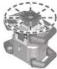
(16) Notch for orientation
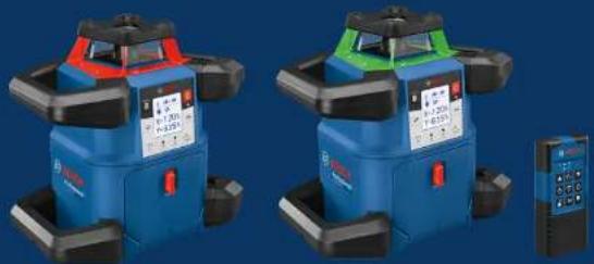
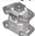
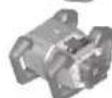
(17) Carrying handle
(18) Tripod mount 5/8" (horizontal)
(19) Laser warning label
(20) Tripod mount 5/8" (vertical)
(21) Serial number
(22) Battery adapter
(23) Release button for rechargeable battery/battery adapter
(24) Rechargeable battery ^b)
a) In vertical mode, the upwards plumb point applies as a 90° reference point.
b) Accessories shown or described are not included with the product as standard. You can find the complete selection of accessories in our accessories range.
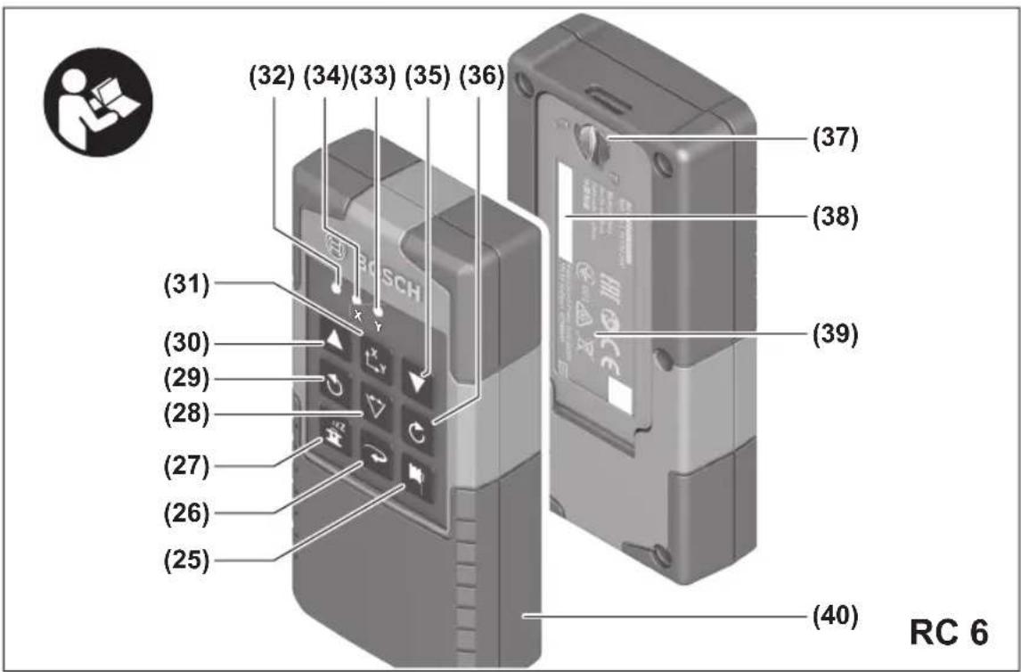
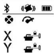
Rotary laser indicator elements
(a) Laser operating mode indicator
(b) Bluetooth® connection indicator
(c) Shock-warning function indicator
(d) Battery charge indicator for rechargeable battery/non-rechargeable batteries
(e) Plumb point function indicator (downwards)
(f) X-axis slope angle indicator
(g) Y-axis slope angle indicator
(h) Rotational speed indicator
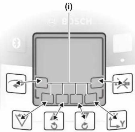
(i) Softkey symbols
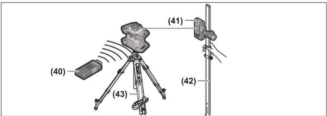
Remote control
(25) Button for plumb point function (downwards)
(26) Rotational operation button
(27) Sleep mode button
(28) Line operation button
(29) Button for anticlockwise rotation
(30) Slope button up
(31) Slope button
(32) Signal transmission indicator
(33) X-axis status indicator
(34) Y-axis status indicator
(35) Slope button down
(36) Button for clockwise rotation
(37) Battery compartment cover locking mechanism
(38) Serial number
(39) Battery compartment cover
(40) Remote control ^a)
a) Accessories shown or described are not included with the product as standard. You can find the complete selection of accessories in our accessories range.
Accessories/replacement parts
(41) Laser receiver ^a)
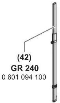
(42) Measuring rod ^a)
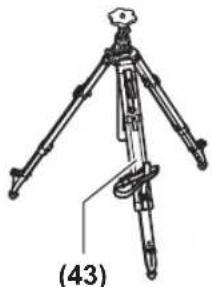
(43) Tripod ^a)
(44) Wall mount/alignment unit ^a)
(45) Fixing holes for wall mount ^a)
(46) Push button for rough adjustment of the wall mount ^a)
(47) Wall mount fine adjustment screw ^a)
(48) 5/8" screw for wall mount ^a)
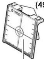
(49) Magnet ^a)
(50) Laser viewing glasses ^a)
(51) Laser target plate ^a)
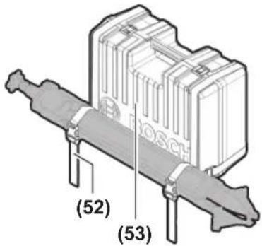
(52) Strap ^a)
(53) Case ^a)
a) Accessories shown or described are not included with the product as standard. You can find the complete selection of accessories in our accessories range.
Technical data
| Rotary laser GRL 600 CHV GRL 650 CHVG |
| Article number | 3 601 K61 F.. 3 601 K61 V.. |
| Working range (radius) | | |
| - Without laser receiver, max. A) | 30 m 35 m |
| - With laser receiver, max. 300 m 325 m | | |
| Levelling accuracy at 30 m distance B)C) | | |
| - horizontal ±1.5 mm ±1.5 mm | | |
| - vertical ±3 mm ±3 mm | | |
| Self-levelling range ±8.5 % (±5°) ±8.5 % (±5°) | | |
| Levelling time (at a slope of up to 3 %) 30 s 30 s | | |
| Rotational speed 150/300/600 min | -1 | 150/300/600 min-1 |
| Single/dual-axis slope operation | ±8.5 % | ±8.5 % |
| Slope operation accuracy B)D) | ±0.2 % | ±0.2 % |
| Max. altitude | 2000 m | 2000 m |
| Relative air humidity max. | 90 % | 90 % |
| Pollution degree according to IEC 61010-1 | 2E) | 2E) |
| Laser class | 2 | 2 |
| Laser type | 630-650 nm, < 1 mW | 500-540 nm, < 1 mW |
| Divergence | < 1.5 mrad (full angle) | < 1.5 mrad (full angle) |
| Recommended laser receiver | LR 60 | LR 65 G |
| Tripod mount (horizontal/vertical) | 5/8" | 5/8" |
| Measuring tool power supply | | |
| - Rechargeable battery (Li-ion) | 18 V | 18 V |
| - Non-rechargeable batteries (alkaline man-ganese) (with battery adapter) | 4 × 1.5 V LR20 (D) | 4 × 1.5 V LR20 (D) |
| Approx. operating time | | |
| - With rechargeable battery (4 Ah) | 60 h | 50 h |
| - With non-rechargeable batteries | 70 h | 60 h |
| Bluetooth® measuring tool | | |
| - Class | 1 | 1 |
| - Compatibility F) | Bluetooth® 5.0/4.X (Low Energy) | Bluetooth® 5.0/4.X (Low Energy) |
| - Max. signal range G) | 100 m 100 m |
| - Operating frequency range | 2402-2480 MHz | 2402-2480 MHz |
| - Max. transmission power | 6.3 mW | 6.3 mW |
| Bluetooth® smartphone | | |
| - Compatibility F) | Bluetooth® 5.0/4.X (Low Energy) | Bluetooth® 5.0/4.X (Low Energy) |
| - Operating system H) | Android 6 (and above) iOS 11 (and above) | Android 6 (and above) iOS 11 (and above) |
38 | English
Rotary laser GRL 600 CHV GRL 650 CHVG
| Weight according to EPTA-Procedure 01:2014 |
| – With rechargeable battery1) | 4.2–4.8 kg 4.2–4.8 kg |
| – With non-rechargeable batteries 4.6 kg 4.6 kg | |
| Dimensions (length × width × height) 327 × 188 × 278 mm 327 × 188 × 278 mm | |
| Protection rating IP68 IP68 | |
| Tipping test height2) | 2 m 2 m |
| Recommended ambient temperature during charging | 0 °C to +35 °C 0 °C to +35 °C |
| Permitted ambient temperature | |
| – During operation –10 °C to +50 °C –10 °C to +50 °C | |
| – During storage –20 °C to +50 °C –20 °C to +50 °C | |
| Recommended rechargeable batteries GBA 18V... | ProCORE18V 4,0 Ah/8,0 Ah | GBA 18V... |
| ProCORE18V 4,0 Ah/8,0 Ah |
| Recommended chargers | GAL 18... | GAL 18... |
| GAX 18... | GAX 18... |
| GAL 36... | GAL 36... |
A) The working range may be reduced by unfavourable environmental conditions (e.g. direct sunlight).
B) At 20°C
C) Along the axes
D) At a maximum slope of ±8.5%, the maximum deviation is ±0.2%.
E) Only non-conductive deposits occur, whereby occasional temporary conductivity caused by condensation is expected.
F) When using Bluetooth® Low Energy devices, it may not be possible to establish a connection depending on the model and operating system. Bluetooth® devices must support the SPP profile.
G) The signal range may vary greatly depending on external conditions, including the receiving device used. The Bluetooth ^® range may be significantly weaker inside closed rooms and through metallic barriers (e.g. walls, shelving units, cases, etc.).
H) Higher versions of the operating system may be necessary depending on the Bosch Levelling Remote App updates.
I) Depends on battery in use
J) The measuring tool, mounted in a horizontal position on a tripod, tips on flat concrete floor.
The serial number (21) on the type plate is used to clearly identify your measuring tool.
| Remote control | RC 6 |
| Article number | 3 601 K69 R.. |
| Max. working range (radius) | 100 m |
| Operating temperature | -10 °C to +50 °C |
| Storage temperature | -20 °C to +70 °C |
| Max. altitude | 2000 m |
| Relative air humidity max. | 90 % |
| Pollution degree according to IEC 61010-1 | 2^A) |
| Bluetooth® remote control |
| - Class | 1 |
| - Compatibility ^B) | Bluetooth® 5.0/4.X (Low Energy) |
| - Max. signal range ^C) | 100 m |
| - Operating frequency range | 2402–2480 MHz |
| - Max. transmission power | 6.3 mW |
| Batteries | 2 × 1.5 V LR6 (AA) |
| Weight according to EPTA-Procedure 01:2014 | 0.17 kg |
| Dimensions (length × width × height) | 122 × 59 × 27 mm |
Remote control RC 6
Protection rating IP54
A) Only non-conductive deposits occur, whereby occasional temporary conductivity caused by condensation is expected.
B) When using Bluetooth® Low Energy devices, it may not be possible to establish a connection depending on the model and operating system. Bluetooth® devices must support the SPP profile.
C) The signal range may vary greatly depending on external conditions, including the receiving device used. The Bluetooth® range may be significantly weaker inside closed rooms and through metallic barriers (e.g. walls, shelving units, cases, etc.).
Assembly
The measuring tool can be operated either with conventional non-rechargeable batteries or with a Bosch lithium-ion battery.
Do not use any commercially available rechargeable batteries (e.g. nickel metal hydride).
Operation with Rechargeable Battery
▶ Use only the chargers listed in the technical data. Only these chargers are matched to the lithium-ion battery of your measuring tool.
Note: The use of batteries unsuitable for your measuring tool can lead to malfunctions or damage to the measuring tool.
Note: The battery is supplied partially charged. To ensure full battery capacity, fully charge the battery in the charger before using your tool for the first time.
The lithium-ion battery can be charged at any time without reducing its service life. Interrupting the charging process does not damage the battery.
The lithium-ion battery is protected against deep discharge by the "Electronic Cell Protection (ECP)". A protective circuit switches the measuring tool off when the battery is drained.
▶ Do not switch the measuring tool back on after it has been switched off by the protective circuit. This can damage the battery.
Battery charge indicator
If the rechargeable battery is removed from the measuring tool, its state of charge may be indicated by the green LEDs of the battery charge indicator on the battery.
Press the button for the battery charge indicator or to show the state of charge.
If no LED lights up after pressing the button for the battery charge indicator, then the battery is defective and must be replaced.
Battery model GBA 18V...

LEDs Capacity
| 3× continuous green light 60-100% |
| 2× continuous green light 30-60% |
| 1× continuous green light 5-30% |
| 1× flashing green light 0-5% |
Battery model ProCORE18V...
LEDs Capacity
| 5× continuous green light 80-100% |
| 4× continuous green light 60-80% |
| 3× continuous green light 40-60% |
| 2× continuous green light 20-40% |
| 1× continuous green light 5-20% |
| 1× flashing green light 0-5% |
Recommendations for Optimal Handling of the Battery
Protect the battery against moisture and water.
Only store the battery within a temperature range of -20 to 50 °C. Do not leave the battery in your car in the summer, for example.
Occasionally clean the ventilation slots on the battery using a soft brush that is clean and dry.
A significantly reduced operating time after charging indicates that the battery has deteriorated and must be replaced. Follow the instructions on correct disposal.
Operation with Non-Rechargeable Batteries
It is recommended that you use alkaline manganese batteries to operate the measuring tool.
Put the batteries into the battery adapter (22). Make sure that the polarity is correct and corresponds to the diagram on the battery adapter.
The battery adapter is intended only for use in designated Bosch measuring tools and must not be used with power tools.
Always replace all the batteries at the same time. Only use batteries from the same manufacturer and which have the same capacity.
▶ Take the batteries out of the measuring tool when you are not using it for a prolonged period of time. The batteries can corrode and self-discharge during prolonged storage in the measuring tool.
To replace the batteries/rechargeable battery, move the locking mechanism (2) of the battery compartment cover into position and open the battery compartment cover (1).
40 | English
Insert either a charged rechargeable battery (24) or the battery adapter (22) with fitted batteries into the battery compartment until you feel it click into place.
To remove the rechargeable battery (24) or battery adapter (22), press the release button (23) and pull the rechargeable battery or battery adapter out of the battery compartment. Do not use force to do this.
Close the battery compartment cover (1) and move the locking mechanism (2) into position
Battery Charge Indicator
The battery charge indicator (d) will indicate the state of charge of the batteries/rechargeable batteries on the display:
Indicator Capacity
| 60 - 100% |
| 30 - 60% |
| 5 - 30% |
| 0 - 5% |

If the batteries or rechargeable battery are empty, a warning message will appear for a few seconds and the status indicator (12) will flash red quickly. The measuring tool will then switch itself off.
Remote control power supply
Using alkali-manganese batteries is recommended to operate the remote control.
Turn the locking mechanism (37) of the battery compartment cover into position (e.g. using a coin). Open the battery compartment cover (39) and insert the batteries.
When inserting the batteries, ensure that the polarity is correct according to the illustration on the inside of the battery compartment.
Close the battery compartment cover (39) and turn the locking mechanism (37) of the battery compartment cover into position
Remove the batteries from the remote control when not using it for longer periods. The batteries can corrode and self-discharge during prolonged storage in the remote control.
Note: The Bluetooth® function remains active as long as batteries are fitted in the remote control. The batteries can be removed in order to prevent energy consumption by this function.
Operation
▶ Protect the measuring tool and remote control against moisture and direct sunlight.
▶ Do not expose the measuring tool or remote control to any extreme temperatures or variations in temperature. For example, do not leave them in a car for extended
periods of time. In case of large variations in temperature, allow the measuring tool and the remote control to adjust to the ambient temperature before putting them into operation. Before continuing work with the measuring tool, always perform an accuracy check (see "Accuracy Check of the Measuring Tool", page 47).
The precision of the measuring tool may be compromised if exposed to extreme temperatures or fluctuations in temperature.
▶ Avoid substantial knocks to the measuring tool and avoid dropping it. Always carry out an accuracy check before continuing work if the measuring tool has been subjected to severe external influences (see "Accuracy Check of the Measuring Tool", page 47).
Starting Operation of the remote control
The remote control will only work if it is fitted with batteries that are sufficiently charged.
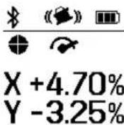
To activate the remote control, press any button on the remote control. The status of the axes on the rotary laser is called up and displayed in the (33) and (34) status indicators on the remote control.
Provided the status indicators are lit up, the relevant setting on the rotary laser is changed with every subsequent press of a button on the remote control. The signal transmission indicator (32) on the remote control lights up to show that a signal is being transmitted.
In order to save energy, the remote control is deactivated after a short time and the (33) and (34) status indicators go out again.
It is not possible to switch the measuring tool on/off with the remote control.
Starting Operation of the rotary laser
▶ Keep the work area free from obstacles that could reflect or obstruct the laser beam. For example, cover any reflective or shiny surfaces. Do not measure through panes of glass or similar materials. The measurements may be distorted by a reflected or obstructed laser beam.
Horizontal position
Vertical position
Position the measuring tool on a stable surface in the horizontal or vertical position, mount it on the tripod (43) or on the wall mount (44) with the alignment unit.
Due to its high levelling accuracy, the measuring tool is very sensitive to knocks and vibrations and changes in position. Take care, therefore, that the measuring tool is stable to avoid interruptions to the operation caused by relevelling.
The main functions of the measuring tool are controlled by the buttons on the measuring tool and the remote control (40). Additional functions are available via the remote control (40), the laser receiver (41), or via the Bosch Levelling Remote App (see "Overview of control options for the functions", page 53).
For the indicator on the measuring tool's display (15), the following applies:
- The current settings for this function will be indicated when a function button (e.g. the line operation button (5)) is pressed for the first time. The settings will be changed the next time a function button is pressed.
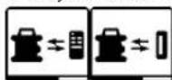
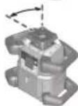
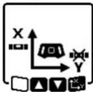
- In the lower part of the display, softkey symbols (i) are shown in various menus. The corresponding function keys (softkeys) arranged around the display can be used to execute the functions represented by the symbols (i) (see figure B). Depending on the corresponding menu, the symbols show the usable function buttons (e.g. the rotational operation button in the rotational operation menu (6)) or additional functions such as Next ( ), Back ( )r Confirm ( ).
- The softkey symbols (i) also make it easy to recognise whether the Slope button down/Button for clockwise rotation (3) and Slope button up/Button for anticlockwise rotation (4) buttons in the current menu are used to slope downwards (▼) or slope upwards (▲) or to turn in a clockwise (♂ or anticlockwise ( ) direction.
- The display will automatically go back to the start screen five seconds after the last press of a button.
- The display (15) will light up with every press of a button or signal that reaches the measuring tool. The light will go out approximately one minute after the last press of a button.
Tilting or rotation in various functions can be accelerated if the respective tilting or rotation buttons on the measuring tool or the remote control are held down for longer. All functions are reset to their standard setting when the measuring tool is switched off.
Switching On and Off
Note: After the first time the tool is started up and before beginning work, you should always perform an accuracy check (see "Accuracy Check of the Measuring Tool", page 47).
To switch on the measuring tool, press the on/off button (11). A start sequence will appear for a few seconds, followed by the start screen. The measuring tool emits the variable laser beam (8) and the upwards plumb point (10) from the outlet apertures (9).
▶ Do not direct the laser beam at persons or animals and do not stare into the laser beam yourself (even from a distance).
The levelling starts automatically and is shown by the flashing symbol for levelling in the display, the flashing laser beams and the status indicator (12) that is flashing green (see "Automatic Levelling", page 44).
After levelling has successfully been completed, the start screen will appear, the laser beams will light up continuously, rotation will start and the status indicator (12) will light up green continuously.

▶ Never leave the measuring tool unattended when switched on, and ensure the measuring tool is switched off after use. Others may be blinded by the laser beam.

To switch off the measuring tool, press and hold the on/off button (11) until the switch-off symbol appears on the display.
If the maximum permitted operating temperature of 50^ C is exceeded, a warning message will appear for a few seconds and the status indicator (12) will flash red.
The measuring tool will then shut down in order to protect the laser diode. Once it has cooled down, the measuring tool is operational again and can be switched back on.
Establishing a connection to the remote control/laser receiver
In the default factory setting, the measuring tool and the remote control (40) and laser receiver (41) supplied are already connected via Bluetooth®.
To connect the remote control or the laser receiver, press and hold the Bluetooth® button (7) until the symbol for establishing a connection with the
remote control/laser receiver appears on the display.
To establish a connection to the remote control, press and hold the button for anticlockwise rotation (29) and the button for clockwise rotation (36) on the remote control at the same time until the status indicators (33) and (34) begin to flash. While the connection to the remote control is being established, the status indicators on the remote control will alternately flash green.
To establish a connection to the laser receiver, press and hold the X-axis and Y-axis buttons on the laser receiver at the same time until the message that a connection has been established appears on the display of the laser receiver. To do this, consult the operating instructions for the laser receiver.
42 | English
It will be confirmed on the display whether a connection has successfully been established to the remote control or the laser receiver. If the attempt to establish a connection to the remote control is successful, the status indicators (33) and (34) on the remote control will light up green for 3 s.

If no connection could be established, an error message will appear on the display.
If the attempt to establish a connec-
tion to the remote control is not successful, status indicators (33) and (34) on the remote control will light up red for 3 s.
Two laser receivers can be connected to and work with the measuring tool at the same time.
If other remote controls or laser receivers are connected, the oldest connection will then be deleted.
Remote control via Bosch Levelling Remote App
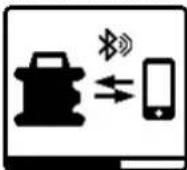
The measuring tool is equipped with a Bluetooth® module which uses radio technology to enable remote control via a smartphone with a Bluetooth® interface.
The Bosch Levelling Remote App application (app) is required to use this function. You can download this in the app store for your terminal device (Apple App Store, Google Play Store).
Information about the system requirements for a Bluetooth® connection can be found on the Bosch website at www.bosch-pt.com
When remote controlling via Bluetooth ^® , poor reception conditions can cause time delays between the mobile terminal device and the measuring tool.
The Bluetooth® function is switched on by default.
To switch off Bluetooth® to control remotely via the app, press the Bluetooth® button (7). The Bluetooth® connection indicator (b) will go out on the start screen.
To switch back on Bluetooth ^® to control remotely via the app, briefly press the Bluetooth ^® button (7). The symbol for establishing a connection to the smartphone will appear on the display.
Ensure that the Bluetooth® interface is
activated on your mobile device.
It will be confirmed on the display whether a connection has successfully been established. The existing connection is visible on the Bluetooth® connection indicator (b) on the start screen.
If no connection could be established, an error message will appear on the display.
The connection between mobile end device and measuring tool is established after the Bosch application has started. If multiple active measuring tools are found, select the appropriate measuring tool. A connection will be established automatically if only one active measuring tool is found.
The Bluetooth ^® connection may be interrupted if the distance between the measuring tool and the mobile device is too great or is blocked, and if there are any sources of electromagnetic interference. In this case, another attempt to establish a connection will automatically begin.
Sleep mode
During breaks from work, you can set the measuring tool to sleep mode. All your settings will still be saved.

To switch on sleep mode, briefly press the on/off button (11). In the menu which subsequently appears, press the on/off button (11) as many times as needed until sleep mode has been selected. Confirm your selection with by pressing the slope
button (14).
Alternatively, you can switch on sleep mode by pressing the sleep mode button (27) on the remote control.

When sleep mode is switched on, the sleep mode symbol will be indicated on the display. The status indicator (12) will slowly flash green. The shock-warning function will remain activated and all settings will be saved.
To switch off sleep mode, briefly press the on/off button (11) on the measuring tool or press the sleep mode button (27) on the remote control.
You can also switch off the measuring tool while it is in sleep mode. Press and hold the on/off button (11) until the switch-off symbol appears on the display. All other buttons on the measuring tool and the remote control will be deactivated.
It is also possible to switch sleep mode on and off via the
Bosch Levelling Remote App.
Locking the keyboard
The keyboard of the measuring tool and the remote control can be locked via the Bosch Levelling Remote App. The keyboard lock symbol will appear on the measuring tool's display.
The keyboard can be unlocked as follows:
- via the Bosch Levelling Remote App,
- by switching the measuring tool on and off via the on/off button (11)
- or by pressing the ▲/ (4) and ▼/ (3) buttons on the measuring tool at the same time.
Operating Modes
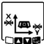
Alignment of X and Y-axis
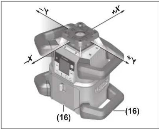
The alignment of the X and Y axes is marked on the housing above the rotation head. The markings are exactly above the alignment notches (16) at the bottom edge of the housing and on the lower handle. The measuring tool can be aligned along the axes by using the alignment notches.
Operating modes overview
All three operating modes are possible with the measuring tool in horizontal and vertical position.
Rotational operation
Rotational operation is especially recommended when using the laser receiver. It is possible to select between different rotational speeds.
Line operation
In this operating mode, the variable laser beam moves within a defined aperture angle. This increases the visibility of the laser beam in comparison to rotational operation. You can select between different aperture angles.
Point operation
In this operating mode, the best visibility of the variable laser beam can be reached. For example, it is used to easily project heights or to check building lines.
Line and point operation are not suitable for use with the laser receiver (41).
Rotational operation
Each time after switching on, the measuring tool is in rotational operation mode with standard rotational speed (600 min ^-1 ).
To switch from line operation to rotational operation, press the rotational operation button (6) or the rotational operation button (26) on the remote control.
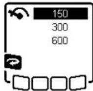
To change the rotational speed, press the rotational operation button (6) or the rotational operation button (26) on the remote control as many times as needed until the required speed is indicated on the display.
The set speed can be seen on the rotational speed indicator (h) on the start screen.
When working with the laser receiver, the highest rotational speed should be set. When not working with the laser receiver, reduce the rotational speed for improved visibility of the laser beam and use the laser googles (50).
Line operation/point operation
To switch to line or point operation, press the line operation button (5) or the line operation button (28) on the remote control.
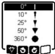
To change the aperture angle, press the line operation button (5) or the line operation button (28) on the remote control until the required operating mode is indicated on the display. The aperture angle is reduced in stages each time a button is pressed until point operation is achieved.
At 360°, the measuring tool is again in rotational operation. The rotational speed is the last set speed.
Note: Due to inertia, it is possible for the laser to slightly move beyond the end point of the laser line.
Turning the line/point within the rotational plane
In line and point operation, the laser line or the laser point can be positioned within the rotational plane of the laser. Rotation is possible by 360°.
To rotate anticlockwise, press the button 3(4) on the measuring tool or the button for anticlockwise rotation (29) on the remote control.
To rotate clockwise, press the button Ⓞ(3) on the measuring tool or the button for clockwise rotation (36) on the remote control.
Turning the rotational plane when in the vertical position
When the measuring tool is in the vertical position, it is possible to rotate the laser point, laser line or rotational plane around the X-axis for easy sighting out or parallel alignment in a range of ± 8.5% .
To start the function, press the slope button (14) on the measuring tool or the slope button (31) on the remote control. The menu for setting the slope of the Y-axis will appear and the symbol for the Y-axis will flash.
To rotate the rotational plane, press the ▲ button (4) or the
▼ button (3) on the measuring tool or the up (30) or
44 | English
down (35) slope button on the remote control until the required position is reached.
Automatic downwards plumb point function in the vertical position
To align the measuring tool against a reference point on the ground when it is in the vertical position, the variable laser beam (8) can be turned downwards to be used as a plumb point. The plumb point function can only be started via remote control or the Bosch Levelling Remote App app. The variable laser beam plumb point is not self-levelling. Therefore, ensure that the measuring tool is levelled in when starting the plumb point function.
To start the downwards plumb point function, press the plumb point function button (25) on the remote control. The plumb point function symbol will appear on the display while the variable laser beam is aligned vertically. After it has been successfully
aligned, the plumb point function indicator (e) will appear on the start screen.
Automatic Levelling
Overview
After switching on, the measuring tool checks the horizontal and vertical position and automatically levels out any unevenness within the self-levelling range of approx. ±8.5% (±5°).
The symbol for levelling flashes on the display during levelling. The status indicator (12) on the measuring tool and the status indicator for the respective axis ((34) or (33)) on the remote control flash green at the same time.
The rotation is stopped until levelling has been completed and the laser beams are flashing. The start screen will appear after levelling has been successfully completed. The laser beams will light up continuously and rotation will start. The status indicator (12) on the measuring tool and the status indicator for the levelled axis ((34) or (33)) on the remote control will light up green continuously.

If the measuring tool is at a slant of more than 8.5% or is positioned differently to the horizontal or vertical position, levelling will no longer be
possible. An error message will appear on the display and the status indicator (12) will flash red.
Reposition the measuring tool and wait for it to re-level.

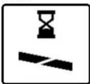
If the maximum levelling time is exceeded, levelling will be discontinued with an error message.
Reposition the measuring tool and briefly press the on/off button (11) to restart levelling.
Position changes
When the measuring tool is levelled in, it continuously checks the horizontal and vertical position. Re-levelling is automatically performed if there are any position changes.
Minimal position changes are levelled out without interrupting the operation. This automatically compensates subsoil ground vibrations or weather influences.
For larger position changes, the rotation of the laser beam will be stopped in order to avoid faulty measurements during the levelling process and the laser beams will flash. The levelling symbol appears on the display. The shock-warning function will be actuated, if required.
The measuring tool will automatically detect the horizontal or vertical position. To change between the horizontal and the vertical position, switch the measuring tool off, reposition it and switch it on again.
If the position is changed without switching on/off, an error message will appear and the status indicator (12) will flash red quickly. Briefly press the on/off button (11) to restart levelling.
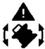
Shock-warning function
The measuring tool has a shock-warning function. After position changes or shock to the measuring tool, or in case of ground vibrations, it keeps the measuring tool from levelling in at changed positions, and thus prevents errors caused by a change in the measuring tool's position.
GRL 650 CHVG: The shock-warning function operates at two sensitivity levels. After the measuring tool is switched on, the setting defaults to high sensitivity.
To activate shock warning:
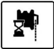
The shock-warning function is switched on by default. It is activated approximately 30 s after the measuring tool has been switched on. During activation, the shock-warning function indicator (c) will flash on the display. The indicator lights up continuously after activation.

Shock warning actuated:
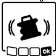
If the position of the measuring tool is changed or a severe knock is registered, the shock warning will be actuated. The laser will stop rotating and an error message will appear. The status indicator (12) will quickly flash red and a warning signal will sound at a fast rate.
Confirm the warning message with 50y pressing the slope button (14) on the measuring tool or the slope button (31) on the remote control. When working with automatic levelling (including slope operation), levelling is automatically re-started.
Now check the position of the laser beam at a reference point and, if necessary, correct the height or alignment of the measuring tool.
To adjust/switch off the shock-warning function:
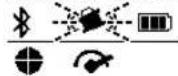
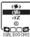
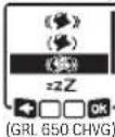
On the start screen, the current setting is shown with the shock-warning indicator (c):
Shock-warning function is switched on at high sensitivity.

GRL 650 CHVG: Shock-warning function is switched on at reduced sensitivity.
Shock-warning function is switched off.
Briefly press the on/off button (11) to adjust the shock-warning function setting. Then press the on/off button (11) in the menu which subsequently appears as many times as needed until the required setting has been selected. Confirm your selection with by pressing the slope button (14).
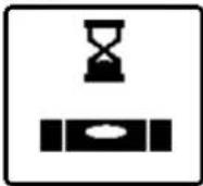
If the shock-warning function has been switched on, it will be activated after approximately 30 seconds.
Slope operation in the horizontal position
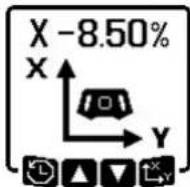
In the measuring tool's horizontal position, the X-axis and the Y-axis can be tilted independently of each other in a range of ±8.5%.
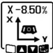
To tilt the X-axis, press the slope button (14) on the measuring tool or the slope button (31) on the remote control once. The menu for setting the slope of the X-axis will appear.
Set the required slope by using the buttons ▲ (4) or ▼ (3) on the measuring tool or using the up (30) or down (35) slope buttons on the remote control. Pressing both slope buttons on the measuring tool or on the remote control at the same time resets the slope back to 0.00%.
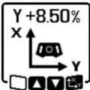
To tilt the Y-axis, press the slope button (14) on the measuring tool or the slope button (31) on the remote control again. The menu for setting the slope of the Y-axis will appear.
Set the required slope in the same way as outlined for the X-axis.
The selected slope is implemented on the measuring tool a few seconds after the last press of a button. Both the laser beam and the symbol for setting the slope on the display will flash until the process of setting the slope has been completed.
After the process of setting the slope has been completed, the set slope values of both axes will be shown on the start screen. The status indicator (12) on the measuring tool will light up red continuously. On the remote control, the status indicator for the tilted axis ((34) and/or (33)) will light up red
continuously.
Slope memory for slope operation in horizontal position (GRL 650 CHVG)
The measuring tool saves the four most recently used slope values of both axes. As an alternative when readjusting the slopes, you can apply these saved slope combinations. Start the slope operation for the X-axis (see "Slope operation in the horizontal position", page 45).
To call up the slope memory, press the line operation button (5) on the measuring tool or the line operation button (28) on the remote control.
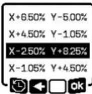
To select one of the four saved combinations, press the line operation button (5) on the measuring tool or the line operation button (28) on the remote control as many times as needed until the required combination is indicated on the display.
Confirm the selection by pressing the slope button (14) on the measuring tool (5) or the slope button (31) on the remote control. The slope combination is implemented on the measuring tool a few seconds after the button is pressed (see "Slope operation in the horizontal position", page 45). To set a value other than one of those saved, press the ▲ button (4) on the measuring tool (5) or the slope up button (30) on the remote control. The indicator returns to the slope operation settings menu (see "Slope operation in the horizontal position", page 45).
SlopeProtect
Temperature changes in the measuring tool can have effects on the set slope of the axes.
To avoid measurement inaccuracies, the slope of the axes is readjusted when exceeding the set temperature difference. The measuring tool is levelled in, then it returns to slope operation with the previously set values.
The slope is reset at temperature changes of ≥5^ .
GRL 650 CHVG: Using the Bosch Levelling Remote App, the temperature difference can be lowered to 2 °C or the SlopeProtect function can be switched off altogether. This setting is not saved when the measuring tool is switched off.
Manual operation
The automatic levelling of the measuring tool can be switched off (manual operation):
46 | English
- in the horizontal position for both axes independently of each other,
- in the vertical position for the X-axis (the Y-axis cannot be levelled in the vertical position).
It is possible to set up the measuring tool at any inclination in the manual operation mode. The axes can also be tilted independently of each other in a range of ±8.5% on the measuring tool. In manual operating mode, the slope value of an axis will not be shown on the display.
The status indicator (12) on the measuring tool will light up red continuously if
- at least one axis is set to manual operating mode in the horizontal position,
- the X-axis is set to manual operating mode in the vertical position.
The Y-axis status indicator (34) or the X-axis status indicator (33) on the remote control light up red continuously if the relevant axis is set to manual operating mode.
Manual operation cannot be started via remote control.
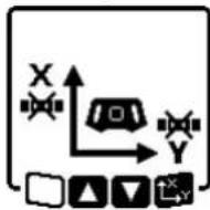
Manual operation in the horizontal position
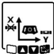
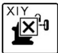
To switch off automatic levelling, press the manual operation button (13) as many times as needed until the required settings combination for both axes is achieved. In the illustrated example, automatic levelling for the X-axis is switched off and the Y-axis continues to be levelled.
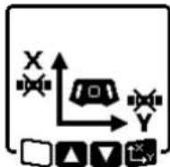
To tilt an axis with automatic leveling switched off, press the slope button (14) while the menu for manual operating mode is displayed.
If automatic levelling is only switched off for one axis, it will only be possible to change the slope of that axis. When manually operating both axes, it is possible to switch between the axes by pressing the slope button (14) again. The symbol for the axis whose slope can be changed will flash.
Tilt the selected axis using the ▲ (4) or ▼ (3) buttons until the required position is reached.
Manual operation in the vertical position
To switch off automatic levelling for the X-axis, press the manual operation button (13) once. (The Y-axis cannot be levelled when in the vertical position.)
To tilt the X-axis without using automatic levelling, press the slope button (14) while the manual operating mode menu is displayed. The symbol for the X-axis will flash on the display.
Tilt the X-axis using the ▲ (4) or ▼ (3) buttons until the required position is reached.

To rotate the Y-axis, press the slope button (14) again while manual operating mode menu is displayed. The symbol for the Y-axis will flash on the display.
Rotate the Y-axis using the ▲ (4) or ▼ (3) buttons until the required position is reached.
Functions
CenterFind mode
In CenterFind mode, the measuring tool automatically attempts to align the laser beam to the centre line of the laser receiver by moving the rotation head up and down. The laser beam can be aligned to the X-axis or the Y-axis of the measuring tool.
CenterFind mode is started at the laser receiver. For this, please read and observe the operating instructions for the laser receiver.
During the search, the CenterFind symbol for one or both axes will appear on the display of the measuring tool and the status indicator (12) will flash red.
If the laser beam was able to be aligned to the centre line of the laser receiver, the CenterFind mode will automatically finish and the slope found will be indicated on the start screen.
If the laser beam could not be aligned with the centre line of the laser receiver, the rotation of the laser beam is stopped and an error message appears in the display. Press any button to close the error message. The corresponding axis is levelled in again to
0%.
Check whether the measuring tool and laser receiver have been set up correctly, and restart the mode. The laser receiver must be situated within the pivoting range of ± 8.5% of the measuring tool.
Note: When using CenterFind mode, the setting of both axes can change, even if one of the axes has not been aligned with the laser receiver.
CenterLock mode (GRL 650 CHVG)
In CenterLock mode, the measuring tool automatically attempts to align the laser beam to the centre line of the laser receiver by moving the rotation head up and down. In contrast to the CenterFind mode, the position of the laser receiver is continuously checked and the inclination of the measuring tool is automatically adjusted. The slope measurements are not shown on the display.
When working in CenterLock mode, take care to ensure that the measuring tool and laser receiver are not accidentally moved. The automatic adjustment of the inclination for every position change can result in measurement errors.
The laser beam can be aligned to the X-axis or the Y-axis of the measuring tool.
CenterLock mode is started and finished at the laser receiver. For this, please read and observe the operating instructions for the laser receiver.
During the search, the CenterLock symbol for one or both axes will appear on the display of the measuring tool and the status indicator (12) will flash red.
If the laser beam could be aligned to the centre line of the laser receiver, the CenterLock symbol for one or both axes will appear on the start screen. The slope measurements are not shown.
If the laser beam could not be aligned with the centre line of the laser receiver, the rotation of the laser beam is stopped and an error message appears in the display. Press any button to close the error message. The corresponding axis is levelled in again to
0%.
Check whether the measuring tool and laser receiver have been set up correctly, and restart the mode. The laser receiver must be situated within the pivoting range of ±8.5% of the measuring tool.
Note: When using CenterLock mode, the setting of both axes can change, even if one of the axes has not been aligned with the laser receiver.
In rotational operation, the variable laser beam (8) can be switched off for one or more quadrants of the rotational plane. This makes it possible to limit the risk related to laser beams to certain areas. Interference from the laser beam that affects other tools or interference with the laser receiver by unintended reflections can also be avoided.
The switching off of individual quadrants can only be controlled by using the Bosch Levelling Remote App. The
quadrants in which the laser beam is visible can be seen in the laser operating mode indicator (a) on the start screen.
The following tasks should be performed only by well-trained and qualified persons. The legalities with regard to performing an accuracy check or calibration of a measuring tool must be known.
Influences on Accuracy
The largest influence is exerted by the ambient temperature. In particular, temperature differences that occur from the ground upwards can refract the laser beam.
In order to minimise thermal influences resulting from heat rising from the floor, it is recommended that you use the measuring tool on a tripod. In addition, position the measuring tool in the centre of the work surface, wherever this is possible.
In addition to external influences, device-specific influences (e.g. falls or heavy impacts) can also lead to deviations. For this reason, check the levelling accuracy each time before beginning work.
If the measuring tool exceeds the maximum deviation for the measuring procedures described below, perform a calibration (see "Calibrating the measuring tool", page 48) or have the measuring tool checked by a Bosch customer service agent.
Checking the levelling accuracy in a horizontal position
For a reliable and precise result, it is recommended that you check the levelling accuracy on a free measuring distance of 30 m on firm ground in front of a wall. Carry out a complete measuring procedure for each of the two axes.
- Mount the measuring tool in a horizontal position 30 m from the wall on a tripod, or place it on a firm, level surface. Switch on the measuring tool.
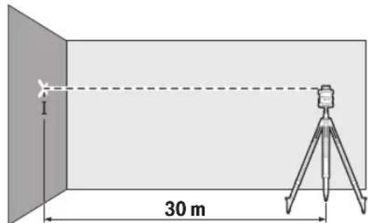
- Once levelling is complete, mark the centre of the laser beam on the wall (point I).
48 | English
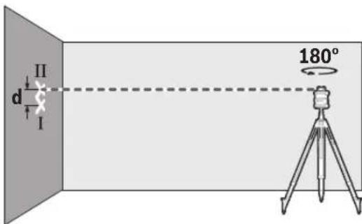
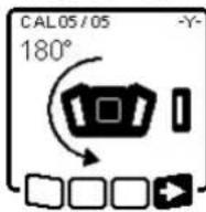
- Turn the measuring tool 180^ without adjusting the height. Allow it to level in and mark the centre point of the laser beam on the wall (point II). Ensure that point II is vertically over or under point I.
Repeat the measuring process for the other axis. To do this, turn the measuring tool by 90° before beginning the measurement.
The maximum permitted deviation on the 30 m measuring distance is as follows: ±1.5 mm. The discrepancy d between points I and II must therefore amount to no more than 3 mm for each of the two measuring processes.
Checking the levelling accuracy in the vertical position
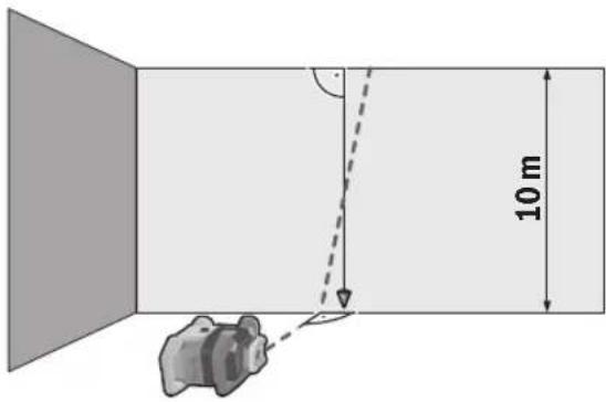
For this check, you will need a free measuring distance on firm ground in front of a 10-metre tall wall. Fix a plumb line to the wall.
- Position the measuring tool in the vertical position on a firm, level surface. Switch the measuring tool on and allow it to level in.
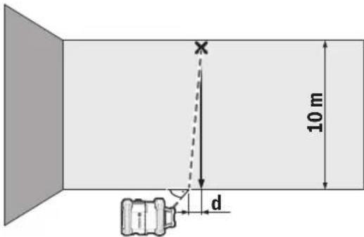
- Set up the measuring tool so that the laser beam meets the plumb line at the exact centre of the upper end. The discrepancy d between the laser beam and the plumb line at the lower end of the line reveals the measuring tool's deviation from the vertical.
For a 10 m high measuring distance, the maximum permitted deviation is as follows: ±1 mm. The discrepancy d must therefore be no more than 1 mm.
The following tasks should be performed only by well-trained and qualified persons. The legalities with regard to performing an accuracy check or calibration of a measuring tool must be known.
▶ Perform calibration of the measuring tool with extreme precision or have the measuring tool checked by a Bosch customer service agent. Inaccurate calibration leads to incorrect measuring results.
▶ Only start the calibration if you have to perform a calibration of the measuring tool. As soon as the measuring tool is in calibration mode, you must perform the calibration meticulously to the end in order to ensure that no incorrect measuring results are produced afterwards.
Check the levelling accuracy after every calibration (see "Accuracy Check of the Measuring Tool", page 47). If the deviation is outside the maximum permitted limits, have the measuring tool checked by a Bosch customer service agent.
X-axis and Y-axis Calibration
The GRL 600 CHV can only be calibrated using the LR 60 laser receiver, and the GRL 650 CHVG can only be calibrated using the LR 65 G. The laser receiver must be connected to the measuring tool via Bluetooth® (see "Establishing a connection to the remote control/laser receiver", page 41).
The positions of the measuring tool and laser receiver cannot be changed during calibration (with the exception of the alignments or rotations described). Therefore position the measuring tool on a firm, level surface and secure the laser receiver.
Calibration should be performed via the Bosch Levelling Remote App if possible. There is less likelihood of error when controlling the tool via the app. Otherwise, the measuring tool's position can be altered if buttons are pressed without due care.
For calibration without the app, the corresponding buttons on the measuring tool must be pressed. It is not possible to use the remote control during calibration.
A free measuring distance of 30 m on a firm surface is required. If no such measuring distance is possible, calibration can also be performed with lower levelling accuracy on a measuring distance of 15 m.
Mount the measuring tool in the horizontal position 30 m or 15 m from the laser receiver on the tripod (43) or position it on a firm, level surface.
Secure the laser receiver at the correct height:
- Either to a wall or to another surface by means of magnets or the suspension hook on the laser receiver,
- or to a securely fastened aid with the holder for the laser receiver.
To do this, consult the operating instructions for the laser receiver.
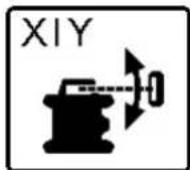
Aligning the measuring tool for calibration:
natural_image
Diagram showing a device with a magnified inset view, no text or symbols present
Align the measuring tool so that the X-axis indicator imprinted on the measuring tool with the "+" side is pointing to the laser receiver. For this, the X-axis must be perpendicular to the laser receiver.
To start calibration:
- For calibration via the Bosch Levelling Remote App: Switch on the measuring tool. Start calibration in the app. Follow the instructions in the app.
- For calibration without the app: Switch on the measuring tool and the laser receiver. Make sure that both of these are connected via Bluetooth®. Start calibration by pressing the on/off button on the laser receiver and the CenterFind mode button on the laser receiver at the same time. "CAL" will appear on the display of the laser receiver.
Press and hold the CenterFind mode button on the laser receiver to cancel the calibration, if required.
To perform calibration without the app:
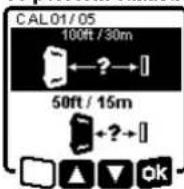
In the menu that appears in the measuring tool display after starting calibration, select the existing distance between the measuring tool and the laser receiver. To do this, press the ▲ button (4) or the ▼ button (3). Confirm your selection with □ pressing the slope button (14).
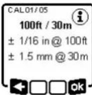
To confirm the selected measuring distance including the corresponding levelling accuracy (express the slope button (14) in the menu which subsequently appears. To go back to selecting the measuring distance ( ), press the line operation button (5).
Align the height of the laser receiver so that the variable laser beam (8) on the laser receiver is indicated as "centred" (see operating instructions for the laser receiver). Secure the laser receiver at this height.
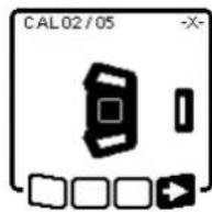
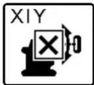
Check whether the measuring tool and laser receiver are aligned with each other, as illustrated on the display (the "+" side of the X-axis is aligned to the laser receiver). Start calibration of the X-axis with by pressing the slope button (14).
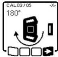
If this step appears on the display, rotate the measuring tool 180° so that the "-" side of the X-axis is directed at the laser receiver. For each rotation, take care not to change the height and inclination of the measuring tool. Confirm the rotation with by pressing the slope button (14). Calibration of
the X-axis continues.
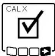
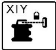
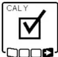
This symbol will appear on the measuring tool display if the X-axis has been successfully calibrated.
Continue calibration with by pressing the slope button (14).
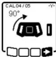
To calibrate the Y-axis, rotate the measuring tool 90° in the direction of the arrow so that the "+" side of the Y-axis is directed at the laser receiver. Confirm the rotation with by pressing the slope button (14).
If this step appears on the display, rotate the measuring tool 180° so that the "-" side of the Y-axis is directed at the laser receiver. Confirm the rotation with -Dy pressing the slope button (14). Calibration of the Y-axis continues.
This symbol will appear on the measuring tool display if the Y-axis has been successfully calibrated.
Finish the calibration of the Y-axis with by pressing the slope button (14).

This symbol confirms that the X-axis and the Y-axis have been successfully calibrated with the levelling accuracy selected at the beginning. End the calibration with ▶y pressing the slope button (14).
If the calibration has been completed successfully, the measuring tool then automatically switches itself off.
50 | English
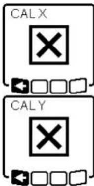
The relevant error message will appear in the measuring tool display if calibration of the X-axis or the Y-axis has not been successful. "ERR" will appear on the display of the laser receiver.
Cancel the calibration with pressing the button for line operation (5).
Make sure that the measuring tool and the laser receiver are aligned correctly (see description above). Restart the calibration.
If calibration fails again, have the measuring tool checked by a Bosch customer service agent.
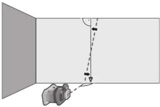
Z-axis calibration
A free measuring distance on firm ground in front of a 10 m wall is required for the calibration. Fix a plumb line to the wall.
Position the measuring tool on a firm, level surface. Switch the measuring tool on and allow it to level in. Align the measuring tool so that the laser beam is perpendicular to the wall and cuts through the plumb line. Switch the measuring tool off.
To start calibration mode, press and hold the slope button (14) and then also briefly press the on/off button (11). The measuring tool is switched on. Allow the measuring tool to level in.
natural_image
Diagram showing a device positioned at an angle with a dashed line indicating direction (no text or symbols)
Align the laser beam so that it runs as parallel as possible to the plumb line.
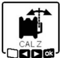
Tilt the laser beam in the ▲ direction by pressing the ▲ button (4). Tilt the laser beam in the ▶ direction by pressing the ▼ button (3).
If it is not possible to align the laser beam in parallel to the plumb line, align the measuring tool to the wall more precisely and start the calibration process again.
If the laser beam is aligned in parallel, save the calibration with by pressing the slope button (14).
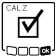
This symbol confirms that the Z-axis has been calibrated successfully. At the same time, the status indicator (12) will flash green three times. End the calibration with 75y pressing the slope button (14).
If the calibration has been completed successfully, the measuring tool then automatically switches itself off.
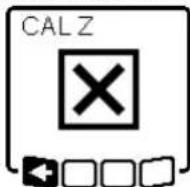
This error message will appear if calibration of the Z-axis has been unsuccessful. Cancel the calibration with by pressing the button for line operation (5).
Ensure that the reference vertical line is in the pivoting range of the rotation head and restart the calibration. Make sure that the measuring tool is not moved during calibration.
If calibration fails again, have the measuring tool checked by a Bosch customer service agent.
Working Advice
▶ Only the centre of the laser point or laser line must be used for marking. The size of the laser point/the width of the laser line changes depending on the distance.
The measuring tool is equipped with a wireless interface. Local operating restrictions, e.g. in aeroplanes or hospitals, must be observed.
Working with the Laser Target Plate
The laser target plate (51) improves visibility of the laser beam in unfavourable conditions and at greater distances. The reflective surface of the laser target plate (51) improves visibility of the laser line. The transparent surface enables the laser line to be seen from behind the laser target plate.
Working with the Tripod (Accessory)
A tripod offers a stable, height-adjustable support surface for measuring. For horizontal operation, place the measuring tool with the 5/8" tripod mount (18) on the thread of the tripod (43). Tighten the measuring tool using the locking screw of the tripod.
For vertical operation, use the 5/8" tripod mount (20).
On a tripod featuring a measuring scale on its extender, you can set the height deviation straight away.
Roughly align the tripod before switching on the measuring tool.
Laser Goggles (Accessory)
The laser goggles filter out ambient light. This makes the light of the laser appear brighter to the eye.
▶ Do not use the laser goggles (accessory) as protective goggles. The laser goggles make the laser beam easier to see; they do not protect you against laser radiation.
▶ Do not use the laser goggles (accessory) as sunglasses or while driving. The laser goggles do not provide full UV protection and impair your ability to see colours.
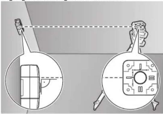
The measuring tool can be secured to the wall using the wall mount with the alignment unit (44). Using the wall mount is recommended, e.g. when working above the maximum extension height of tripods, or when working on unstable surfaces without a tripod.
Fasten the wall mount (44) to a wall using screws through the fixing holes (45). Fit the wall mount as vertical as possible and ensure it is mounted in a stable way.
Screw the 5/8" wall mount screw (48) into the horizontal tripod mount (18), depending on the requirements of the task, or the vertical tripod mount (20) on the measuring tool.
Using the alignment unit allows the measuring tool to be moved in a range of approx. 13 cm with respect to height. Press the button (46) and move the alignment unit to roughly the required height. It is possible to align the laser beam precisely to a reference height using the fine adjustment screw (47).
To check levels or apply slopes, it is recommended to use the measuring rod (42) together with the laser receiver.
A relative measuring scale is incorporated at the top of the measuring rod (42). You can preselect its zero at the bottom on the extender. This enables you to read deviations from the target height straight away.
Example applications
Position the measuring tool in the horizontal position on a firm support or mount it on a tripod (43) (accessory).
Working with a tripod: Set the laser beam at the required height. Project or check the height at the target location. Working without a tripod: Determine the height difference between the laser beam and the height at the reference point using the laser target plate (51). Project or check the height difference measured at the target location.
When right angles are to be projected or partition walls are to be aligned, the upwards plumb point (10) must be aligned in parallel, meaning at the same distance to a reference line (e.g. a wall).
For this, set up the measuring tool in the vertical position and position it in such a manner that the upwards plumb point runs approximately parallel to the reference line.
For the exact positioning, measure the clearance between the upwards plumb point and reference line directly on the measuring tool using the laser target plate (51). Measure the clearance between the upwards plumb point and reference line again as far away as possible from the measuring tool. Align the upwards plumb point in such a manner that it has the same clearance to the reference line as when measured directly at the measuring tool.
The right angle to the upwards plumb point (10) is indicated by the variable laser beam (8).
To indicate a perpendicular or a vertical plane, set up the measuring tool in the vertical position. When the vertical plane is supposed to run at a right angle to a reference line (e.g. a wall), align the upwards plumb point (10) with this reference line.
The perpendicular plane is indicated by the variable laser beam (8).
To align the vertical laser line or the rotational plane against a reference point on a wall, set up the measuring tool in the vertical position, and roughly align the laser line or the rotational plane with the reference point. For precise alignment with the reference point, turn the rotational plate around the X-axis (see "Turning the rotational plane when in the vertical position", page 43).
Working without the laser receiver
Under favourable light conditions (dark environment) and for short distances, it is possible to work without the laser receiver. For improved visibility of the laser beam, either select line operation or point operation and rotate the laser beam to the target location.
In unfavourable lighting conditions (bright environment, direct sunlight) and for larger distances, use the laser receiver
52 | English
to improve detection of the laser beam (41). When working with the laser receiver, select rotational operation with the highest rotational speed.
The laser receiver (41) should always be used when working outdoors.
When working on unstable ground, mount the measuring tool on the tripod (43). Always work with the shock-warning function activated in order to avoid faulty measurements in case of ground movements or shocks to the measuring tool.
Mount the measuring tool in the horizontal position on a tripod (43) and set up the tripod outside the formwork area. Select rotational operation.
Secure the laser receiver (41) to a measuring rod (42) with the holder. Position the measuring rod on a reference point for the formwork.
Align the height of the laser receiver on the measuring rod so that the variable laser beam (8) of the measuring tool is indicated as "centred" (see operating instructions for the laser receiver).
Then position the measuring rod with the laser receiver, one after the other, at different test locations on the formwork.
Make sure that the laser receiver remains in the same position on the measuring rod.
Correct the height of the formwork until the laser beam is indicated as "centred" at all test locations.
Mount the measuring tool in the horizontal position on a tripod (43). Select rotational operation.
Set up the tripod with the measuring tool so that the X-axis is aligned with the slope that is to be checked.
Set the target slope as the slope for the X-axis (see "Slope operation in the horizontal position", page 45).
Secure the laser receiver (41) to a measuring rod (42) with the holder. Place the measuring rod at the base of the slope surface.
Align the height of the laser receiver on the measuring rod so that the variable laser beam (8) of the measuring tool is indicated as "centred" (see operating instructions for the laser receiver).
Then position the measuring rod with the laser receiver, one after the other, at different test locations on the slope surface. Make sure that the laser receiver remains in the same position on the measuring rod.
If the slope of the plane is correct, the laser beam will be indicated as "centred" at all test locations.
Overview of status indicators

Green Red
○ Horizontal position: X- or Y-axis levelling process
Vertical position: X-axis levelling process
- Sleep mode activated
● Horizontal position: Both axes are levelled.
Vertical position: X-axis is levelled.
Automatic shut-down due to error message (e.g. empty rechargeable/non-rechargeable battery, operating temperature exceeded)
CenterFind mode or CenterLock mode started (see operating instructions for the laser receiver)
- Position of the measuring tool changed without switching on/off
Self-levelling not possible, end of the self-levelling range
- Shock-warning function actuated
- Calibration of the measuring tool is started.
● Horizontal position: At least one axis is tilted or is in manual operating mode. Vertical position: X-axis is tilted or in manual operating mode.
● lighting up continuously
- flashing
| Remote control | Remote control | Function |
| D=1643 | D=4543 | |
| Green Red Green Red |
Green Red Green Red
- X-axis levelling process (horizontal and vertical positions)
○ Y-axis levelling process (horizontal position)
○ Remote control is being connected via Bluetooth®.
(Both of the status indicators flash alternately.)
● X-axis is levelled in (horizontal and vertical positions).
● Y-axis is levelled in (horizontal position).
● (3 s) ● (3 s) Remote control successfully connected via Bluetooth®
● X-axis is tilted or in manual operating mode (horizontal and vertical positions).
● Y-axis is tilted or in manual operating mode (horizontal position).
● (3 s) ● (3 s) Unsuccessful connection to the measuring tool via Bluetooth®
● lighting up continuously
- flashing
Overview of control options for the functions
| Function GRL 600 | CHV | GRL 650 CHVG | RC 6 LR 60 LR 65 G Bosch Levelling |
| | Remote App |
| Switching the GRL 600 CHV/GRL 650 CHVG on and off | ● ● - - - - | | | | |
| Establish connection via Bluetooth ^®A | ● ● | ● | ● | ● | ● |
| Sleep mode | ● | ● | ● | - | - |
| Switching on the keyboard lock | - | - | - | - | - |
| Switching off the keyboard lock | ● ● - - - | ● | | | |
| Rotation, line and point operation | ● | ● | ● | - | - |
| Turning the line/point within the rotational plane | ● | ● | ● | - | - |
| Turning the rotational plane when in the vertical position | ● ● | ● | -- | | ● |
| Automatic downwards plumb point function in the vertical position | - | - ● | -- | | ● |
| Switching on/off the shock-warning function | ● ● - - - | ● | | | |
| Adjusting the shock-warning function sensitivity | - | ● | - | - | - |
| Slope operation | ● | ● | ● | - | - |
| Changing SlopeProtect (GRL 650 CHVG) | - | - | - - - - | | ● |
| Manual operation | ● ● - - - | ● | | | |
| CenterFind mode | - | - | - | ● | ● |
| CenterLock mode | - | - | -- | ● | - |
| Mask mode | - | - | - | - | - |
| X-axis and Y-axis calibration (horizontal position) ^B) | ● ● - | ● | ● | | ● |
| Z-axis calibration (vertical position) | ● ● - - - | ● | | | |
A) The function must be started on both the measuring tool and the remote control, laser receiver or smart phone at the same time.
B) The function must be started on both the measuring tool and the smartphone at the same time or on the laser receiver.
54 | English
Rectifying errors
| Rotary laser display indicator | Laser receiver display indicator | Problem Corrective measure |
 | - Automatic shut-down (empty rechargeable/non-rechargeable battery) | Change the rechargeable or non-rechargeable battery as necessary. |
 | - Automatic shut-down (operating temperature exceeded) | Adjust the measuring tool to the ambient temperature before switching it on. Then check the measuring accuracy and calibrate the measuring tool if required. |
 | -/PNK | Unsuccessful attempt to connect to the remote control (40) or the laser receiver (41) | Briefly press the on/off button (11) to close the error message. Start the connection process again (see "Establishing a connection to the remote control/laser receiver", page 41).If it is not possible to establish a connection, please contact a Bosch customer service agent. |
 | - Unsuccessful attempt to connect to the mobile device | Briefly press the on/off button (11) to close the error message. Start the connection process again (see "Remote control via Bosch Levelling Remote App", page 42).If it is not possible to establish a connection, please contact a Bosch customer service agent. |
 | - Measuring tool is at a slant of more than 8.5 % or is not in the correct horizontal or vertical position. | Reposition the measuring tool so that it is in either the horizontal or vertical position. The re-levelling will start automatically. |
 | - Maximum levelling time is exceeded | Reposition the measuring tool so that it is in either the horizontal or vertical position. Briefly press the on/off button (11) to restart levelling. |
 | - Change between the horizontal and vertical position without switching the measuring tool on/off | Briefly press the on/off button (11) to restart levelling. |
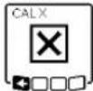 | ERR | Unsuccessful calibration of the X-axis | Cancel the calibration with pressing the button for line operation (5).Ensure that the receiving field of the laser receiver is perpendicular to the corresponding axis (X/Y) of the measuring tool. Restart the calibration. |
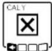 | ERR | Unsuccessful calibration of the Y-axis |
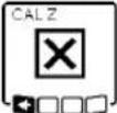 | - Unsuccessful calibration of the Z-axis | Cancel the calibration with pressing the button for line operation (5). Check that the measuring tool is aligned correctly and restart calibration. |
 | ERR Unsuccessful CenterFind mode in relation to the X-axis | Press any button to close the error message.Check whether the measuring tool and laser receiver have been set up correctly. The laser receiver must be situated within the pivoting range of ±8.5 % of the measuring tool.Restart the mode. |
| Rotary laser display indicator | Laser receiver display indicator | Problem Corrective measure |
| ERR Unsuccessful CenterFindmode in relation to the Y-axis |
GRL 650 CHVG:
| ERR | Unsuccessful CenterLock mode in relation to the X-axis |
| Press any button to close the error message. |
| Check whether the measuring tool and laser receiver have been set up correctly. The laser receiver must be situated within the pivoting range of ± 8.5 % of the measuring tool. |
| Restart the mode. |
| ERR Unsuccessful CenterLockmode in relation to the Y-axis |
Maintenance and Service
Maintenance and Cleaning
Keep the measuring tool and the remote control clean at all times.
Do not immerse the measuring tool and remote control into water or other fluids.
Wipe off any dirt using a damp, soft cloth. Do not use any detergents or solvents.
In particular, regularly clean the surfaces at the outlet aperture of the laser on the measuring tool and make sure to check for any lint.
Only store and transport the measuring tool in the case (53). If the measuring tool needs to be repaired, send it off in the case (53).
When transporting the measuring tool in the case (53), the tripod (43) can be secured to the case with the strap (52).
After-Sales Service and Application Service
Our after-sales service responds to your questions concerning maintenance and repair of your product as well as spare parts. You can find explosion drawings and information on spare parts at: www.bosch-pt.com
The Bosch product use advice team will be happy to help you with any questions about our products and their accessories.
In all correspondence and spare parts orders, please always include the 10-digit article number given on the nameplate of the product.
Great Britain
Robert Bosch Ltd. (B.S.C.)
P.O. Box 98
Broadwater Park
North Orbital Road
Denham Uxbridge
UB 9 5HJ
At www.bosch-pt.co.uk you can order spare parts or arrange
the collection of a product in need of servicing or repair.
Tel. Service: (0344) 7360109
E-Mail: boschservicecentre@bosch.com
You can find further service addresses at:
www.bosch-pt.com/serviceaddresses
Transport
The contained lithium-ion batteries are subject to the Dangerous Goods Legislation requirements. The batteries are suitable for road-transport by the user without further restrictions.
When shipping by third parties (e.g.: by air transport or forwarding agency), special requirements on packaging and labelling must be observed. For preparation of the item being shipped, consulting an expert for hazardous material is required.
Dispatch battery packs only when the housing is undamaged. Tape or mask off open contacts and pack up the battery in such a manner that it cannot move around in the packaging. Please also observe the possibility of more detailed national regulations.
Disposal

Electrical and electronic equipment, batteries, accessories and packaging should be sorted for environmentally friendly recycling.

Do not dispose of electrical and electronic equipment and batteries in household waste!
Only for EU countries:
In accordance with Directive 2012/19/EU and Directive 2006/66/EC respectively, electrical and electronic equipment that is no longer usable and defective/drained batteries must be collected separately and recycled in an environmentally friendly manner.
56 | English
Battery packs/batteries:
Li-ion:
Please observe the notes in the section on transport (see
"Transport", page 55).
Table des matières

natural_image
Technical diagram showing two views of a mechanical component with alignment lines (no text or symbols)
natural_image
Diagram showing a camera setup with an object near a mirror, no text or symbols present
Robert Bosch (France) S.A.S.
www.bosch-pt.com/serviceaddresses
Transport
natural_image
Diagram showing two views of a device with internal components and a close-up view of the internal structure (no text or symbols)
natural_image
Diagram showing a camera setup with an object near a mirror, no text or symbols present
Controlo remoto via Bosch Levelling Remote App
natural_image
Technical diagram showing a device with a magnified inset view of its internal structure (no text or symbols present)
natural_image
Diagram showing a vehicle with a car and a vertical dashed line, no text or symbols present
www.bosch-pt.com/serviceaddresses
Transporte

natural_image
Technical diagram showing a device with a magnified inset view of its internal structure (no text or symbols present)
natural_image
Diagram showing a vehicle with a dashed trajectory line and angle markers, no text or symbols present
www.bosch-pt.com/serviceaddresses
Trasporto
natural_image
Diagram showing a device with a magnified inset view of its internal structure, no text or symbols present.
natural_image
Diagram showing a vehicle with a sensor or camera setup, no text or symbols present
www.bosch-pt.com/serviceaddresses
Vervoer
(20) Stativholder 5/8" (lodret)
(21) Serienummer
(22) Batteriadapter
(23) Oplåsningsknap akku/batteriadapter
(24) Akku ^b)

- via Bosch Levelling Remote App,
natural_image
Diagram showing a device with a lens and internal components, including a close-up view of the lens (no text or symbols present)
natural_image
Diagram showing a camera setup with a lens and directional arrows, no text or symbols present
196 | Dansk
Bosch Service Center
Telegrafvej 3
2750 Ballerup
På www.bosch-pt.dk kan der online bestilles reservedele eller oprettes en reparations ordre.
Tlf. Service Center: 44898855
Fax: 44898755
E-Mail: vaerktoej@dk.bosch.com
www.bosch-pt.com/serviceaddresses
Transport
Bosch Levelling Remote App.
Knapplås

natural_image
Diagram showing a person viewing a device with a magnified inset of its side view (no text or symbols present)
natural_image
Diagram showing a vehicle in a corner with a dashed line indicating direction and angle, no text or symbols present
Bosch Service Center
Telegrafvej 3
2750 Ballerup
Danmark
Tel.: (08) 7501820 (inom Sverige)
Fax: (011) 187691
www.bosch-pt.com/serviceaddresses
Transport
(16) Hakk for innstilling
(17) Bærehåndtak
(18) Stativfeste 5/8" (horisontalt)
(19) Laservarselskilt
(20) Stativfeste 5/8" (vertikalt)
(21) Serienummer
(22) Batteriadapter
(23) Utløserknapp for oppladbart batteri/batteriadapter
(24) Oppladbart batteri ^b)
a) I vertikal modus gjelder loddpunktet oppover som 90°-referansepunkt.
natural_image
Simple line drawing of a thermometer inside a rectangular device (no text or symbols)
- via Bosch Levelling Remote App,
natural_image
Technical diagram showing two views of a device with internal components and alignment lines (no text or symbols)
natural_image
Diagram showing a 3D object with a dashed line and angle markers, no text or symbols present
www.bosch-pt.com/serviceaddresses
Transport

natural_image
Diagram showing a vehicle in a corner with a dashed line indicating direction and angle, no text or symbols present.
264|Suomi
www.bosch-pt.com/serviceaddresses
Kuljetus
natural_image
Technical diagram showing two views of a device with a magnified inset, no text or symbols present.
natural_image
Diagram showing a vehicle in a corner with a dashed line indicating direction and angle, no text or symbols present.
natural_image
Pure black dots arranged in two rows on white background (no text or symbols)
292 | Ελληνικά
www.bosch-pt.com/serviceaddresses
Μεταφορά
Uzaktan kumanda Bosch Levelling Remote App
natural_image
Diagram showing two views of a device with internal components and a close-up view of the screen (no text or symbols)
www.bosch-pt.com/serviceaddresses
Nakliye
natural_image
Technical diagram showing two views of a mechanical component with no visible text or symbols
natural_image
Diagram showing a vehicle with a sensor or camera system projecting a vertical beam, no text or symbols present
Robert Bosch Sp. z o.o.
www.bosch-pt.com/serviceaddresses
Transport
natural_image
Diagram showing a device with a screen and a close-up view of its internal components (no text or symbols present)
natural_image
Diagram showing a vehicle in a room with an arrow indicating direction and angle, no text or symbols present
Bosch Service Center PT
K Vápence 1621/16
692 01 Mikulov
www.bosch-pt.com/serviceaddresses
Přeprava
natural_image
Diagram showing a camera setup with an object near a mirror, no text or symbols present
www.bosch-pt.com/serviceaddresses
Transport
natural_image
Diagram showing a vehicle with a car and a vertical dashed line, no text or symbols present
www.bosch-pt.com/serviceaddresses
Szállítás
natural_image
Diagram showing a vehicle in a room with a dashed line indicating direction and angle, no text or symbols present
www.bosch-pt.com/serviceaddresses
Транспортировка
natural_image
Simple icon of a thermometer with an exclamation mark above it, no text or symbols present.
natural_image
Diagram showing a device with a magnified inset view of its internal structure (no text or symbols present)
natural_image
Diagram showing a room with a wall-mounted device and a dashed line indicating direction, no text or symbols present.
www.bosch-pt.com/serviceaddresses
Транспортування
natural_image
Diagram showing a device with a screen and a close-up view of its internal components (no text or symbols present)
natural_image
Diagram showing a vehicle with a sensor or camera system projecting onto a panel, with no visible text or symbols.
www.bosch-pt.com/serviceaddresses
Тасымалдау
natural_image
Diagram showing a camera setup with an object near a mirror, no text or symbols present
Service scule electrice
Strada Horia Măcelariu Nr. 30-34, sector 1
013937 Bucureşti
www.bosch-pt.com/serviceaddresses
Transport

- през Bosch Levelling Remote App,
natural_image
Diagram showing a vehicle in a corner with a dashed line indicating direction and angle, no text or symbols present.
Service scule electrice
Strada Horia Măcelariu Nr. 30–34, sector 1 013937 București, România
www.bosch-pt.com/serviceaddresses
Транспортиране
natural_image
Diagram showing a person using a device to observe a device with a magnified view of the interior (no text or symbols present)
natural_image
Diagram showing a vehicle with a downward arrow and angle measurement, no text or symbols present
www.bosch-pt.com/serviceaddresses
Транспорт
- Merni alat okrenite za 180°, a da ne pomerate visinu. Ostavite ga da se niveliše i označite sredinu laserske tačke na zidu (tačka II). Vodite računa o tome da se tačka II uspravno nalazi iznad odnosno ispod tačke I.
Ponovite radnju merenja za drugu osu. Okrenite merni alat pre početka merenja za 90°.
Na mernoj deonici od 30 m maksimalno dozvoljeno odstupanje iznosi ±1,5 mm. Razlika d između tačaka I i II dakle pri svakom od dva procesa merenja sme da iznosi najviše 3 mm.
Provera preciznosti nivelacije u vertikalnom položaju
Za proveru vam je potrebna slobodna merna deonica od 10 m na čvrstoj podlozi ispred zida. Pričvrstite na zid jedan vertikalan kanap.
- Postavite merni alat u vertikalnom položaju na čvrstu, ravnu podlogu. Uključite merni alat i pustite ga da se niveliše.
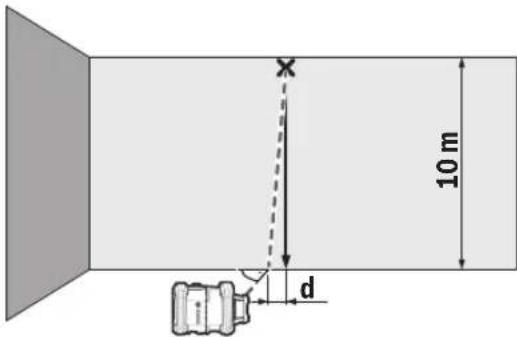
- Centrirajte tako merni alat, da laserski zrak vertikalni kanap tačno pogada po sredini na gornjem kraju. Razlika d između laserskog zraka i vertikalnog kanapa na donjem kraju kanapa prikazuje odstupanje mernog alata od vertikale.
Kod merne deonice od 10 m maksimalno dozvoljeno odstupanje iznosi ±1 mm. Razlika d dakle sme da iznosi najviše 1 mm.
Kalibrisanje mernog alata
Sledeće radove smeju da obavljaju isključivo dobro obučene i kvalifikovane osobe. Moraju biti upoznati sa pravilnim postupkom sprovođenja provere tačnosti kalibracije mernog alata.
- Kalibraciju mernog alata izvršite naročito precizno ili proverite merni alat u Bosch servisnoj službi.
Neprecizna kalibracija dovodi do pogrešnih rezultata u merenju.
Pokrenite kalibraciju samo kada je neophodno izvršiti kalibrisanje mernog alata. Kada merni alat bude u režimu kalibracije, prvo morate da izvršite kalibraciju vrlo precizno i do kraja, kako se kasnije ne bi generisali netačni rezultati merenja.
natural_image
Diagram showing a person standing in a circular device with a close-up inset of its body and internal components (no text or symbols)
Usmerite merni alat tako, da utisnuti prikaz X-osa na mernom alatu "+" stranom pokazuje ka laserskom prijemniku. X-osa pritom mora da stoji vertikalno u odnosu na laserski prijemnik.
Pokretanje kalibracije:
- Kalibracija preko Bosch Levelling Remote App: Uključite merni alat. Pokrenite kalibraciju u aplikaciji. Pratite u nastavku uputstva u aplikaciji.
- Kalibracija bez aplikacije: Uključite merni alat i prijemnik lasera. Uverite se, da su oni povezani putem Bluetooth® veze. Započnite kalibraciju istovremenim pritiskom tastera za uključivanje/isključivanje prijemnika lasera kao i tastera za režim rada CenterFind na prijemniku lasera. Na displeju prijemnika lasera se pojavljuje CAL.
Za prekid kalibracije po potrebi, dugo pritiskajte taster za režim rada CenterFind na prijemniku lasera.
584 | Srpski
Vršenje kalibracije bez aplikacije:
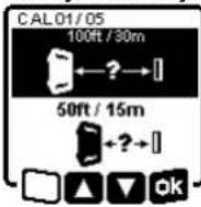
U meniju koji se nakon početka kalibracije pojavljuje na displeju mernog alata, izaberite postojeće rastojanje između mernog alata i prijemnika lasera. U tu svrhu pritisnite taster ▲ (4) odn. ▼ (3). Svoj izbor potvrdite sa apritiskom tastera za podešavanje nagiba (14).
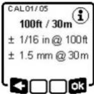
Za potvrdu izabrane merne deonice uključujući pripadajuću preciznost nivelisanja u sledećem meniju pritisnite taster za podešavanje nagiba (14). Za povratak na izbor merne deonice pritisnite taster za linijski režim rada (5).
Podesite prijemnik lasera po visini tako, da se varijabilni laserski zrak (8) na prijemniku lasera prikazuje u sredini (pogledajte uputstvo za rukovanje prijemnikom lasera). Pričvrstite prijemnik lasera sigurno na tu visinu.
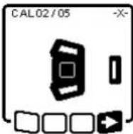
Proverite da li su merni alat i prijemnik lasera usmereni jedan prema drugom kao što je prikazano na slici (+" strana X-ose je usmerena prema prijemniku lasera). Počnite kalibraciju X-ose pomoću -pritiskom tastera za podešavanje nagiba (14).
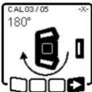
natural_image
Diagram showing a camera setup with an object near a mirror, no text or symbols present
Usmerite laserski zrak tako da on bude što paralelniji sa vertikalnim kanapom.
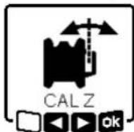
Nagnite laserski zrak u pravcu ◀, pritiskom na taster ▲ (4). Nagnite laserski zrak u pravcu ▶, pritiskom na taster ▼ (3).
Ako nije moguće da se laserski zrak usmeri paralelno sa vertikalnim kanapom, usmerite merni alat precizno ka zidu i ponovo započnite proces kalibracije.
Ako je laserski zrak paralelno usmeren, memorišite kalibraciju pomoću opritiskom tastera za podešavanje nagiba (14).
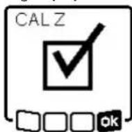
Ovaj simbol potvrđuje uspešnu kalibraciju Z-ose. Istovremeno prikaz statusa (12) 3x treperi u zelenoj boji. Završite kalibraciju pomoću pritiskom tastera za podešavanje nagiba (14).
www.bosch-pt.com/serviceaddresses
Transport
Akumulatorske baterije koje sadrže litijum jon podležu zahtevima prava o opasnim materijama. Akumulatorske baterije korisnik može transportovati na drumu bez drugih pakovanja.
Kod slanja preko trećih lica (na primer vazdušnih transportom ili špedicijom) mora se obratiti pažnja na posebne zahteve u pogledu pakovanja i označavanja. Tada se kod pripreme paketa za slanje mora pozvati stručnjak za opasne materije.
Akumulatorske baterije šaljite samo ako kućište nije oštećeno. Odlepite otvorene kontakte i upakujte akumulatorsku bateriju tako, da se ne pokreće u paketu.
Molimo da obratite pažnju na eventualne dalje nationalne propise.
Uklanjanje dubreta

Električne uredaje, akumulatore/baterije, pribor i pakovanja treba predati na reciklažu koja je u skladu sa zaštitom životne sredine.


Če je akumulatorska baterija oz. baterije prazna, se za nekaj sekund pojavi opozorilo in prikaz stanja (12) utripa hitro rdeče. Nato se merilna naprava izklopi.
← □ □ ok
(GRL 650 CHVG)
natural_image
Diagram showing a device with a magnified inset view, no text or symbols present
natural_image
Diagram showing a camera setup with a lens and a car, no text or symbols present
Ako su aku-baterija ili baterije prazne, nekoliko sekundi se prikazuje upozorenje, a indikator statusa (12) brzo treperi crveno. Zatim se mjerni alat isključuje.
- putem Bosch Levelling Remote App
624 | Hrvatski
natural_image
Technical diagram showing two views of a mechanical component with internal structure and alignment lines (no text or symbols)
natural_image
Diagram showing a camera setup with an object near a mirror, no text or symbols present
Usmjerite lasersku zraku tako da je po mogućnosti položena paralelno s uzicom viska.

Nagnite lasersku zraku u smjeru ▶ na način da pritisnete tipku ▲ (4).
Nagnite lasersku zraku u smjeru ▶ na način da pritisnete tipku ▼ (3).
www.bosch-pt.com/serviceaddresses
Transport
Litij-ionske aku-baterije podliježu zakonu o transportu opasnih tvari. Korisnik bez ikakvih preduvjeta može transportirati aku-baterije cestovnim transportom.
natural_image
Diagram showing two views of a device with internal components and alignment lines (no text or symbols)
natural_image
Diagram showing a vehicle with a dashed trajectory line and angle markers, no text or symbols present
www.bosch-pt.com/serviceaddresses
Transport

natural_image
Diagram showing a person using a device to observe a screen with a magnified view of the screen (no text or symbols present)
natural_image
Diagram showing a device positioned at an angle with a dashed line indicating direction (no text or symbols)
www.bosch-pt.com/serviceaddresses
Transportešana
natural_image
Diagram showing a device with a magnified view of its internal structure, including a circular component and a close-up of its internal components (no text or symbols present)
natural_image
Diagram showing a vehicle with a downward arrow and angle measurement, no text or symbols present
www.bosch-pt.com/serviceaddresses
Transportavimas
natural_image
Simple line drawing of a thermometer inside a device (no text or symbols)
عند تشغيل تطبيق بوش، يتم إنشاء اتصال بين الجهاز
النقالPositivePositivePositivePositivePositivePositivePositivePositivePositivePositivePositivePositivePositivePositivePositivePositivePositivePositivePositivePositivePositivePositivePositivePositivePositivePositivePositivePositivePositivePositivePositivePositivePositivePositivePositivePositivePositivePositivePositivePositivePositivePositivePositivePositivePositivePositivePositivePositivePositivePositivePositivePositivePositivePositivePositivePositivePositivePositivePositivePositivePositivePositivePositivePositivePositivePositivePositivePositivePositivePositivePositivePositivePositivePositivePositivePositivePositivePositivePositivePositivePositivePositivePositivePositivePositivePositivePositivePositivePositivePositivePositivePositivePositivePositivePositivePositivePositivePositivePositivePositive Positive Positive Positive Positive Positive Positive Positive Positive Positive Positive Positive Positive Positive Positive Positive Positive Positive Positive Positive Positive Positive Positive Positive Positive Positive Positive Positive Positive Positive Positive Positive Positive Positive Positive Positive Positive Positive Positive Positive Positive Positive Positive Positive Positive Positive Positive Positive Positive Positive Positive Positive Positive Positive Positive Positive Positive Positive Positive Positive Positive Positive Positive Positive Positive Positive Positive Positive Positive Positive Positive Positive Positive Positive Positive Positive Positive Positive Positive Positive Positive Positive Positive Positive Positive Positive Positive Positive Positive Positive Positive Positive Positive Positive Positive Positive Positive Positive Positive Positive Positive Negative Negative Negative Negative Negative Negative Negative Negative Negative Negative Negative Negative Negative Negative Negative Negative Negative Negative Negative Negative Negative Negative Negative Negative Negative Negative Negative Negative Negative Negative Negative Negative Negative Negative Negative Negative Negative Negative Negative Negative Negative Negative Negative Negative Negative Negative Negative Negative Negative Negative Negative Negative Negative Negative Negative Negative Negative Negative Negative Negative Negative Negative Negative Negative Negative Negative Negative Negative Negative Negative Negative Negative Negative Negative Negative Negative Negative Negative Negative Negative Negative Negative Negative Negative Negative Negative Negative Negative Negative Negative Negative Negative Negative Negative Negative Negative Negative Negative Negative Negative Positive Positive Positive Positive Positive Positive Positive Positive Positive Positive Positive Positive Positive Positive Positive Positive Positive Positive Positive Positive Positive Positive Positive Positive Positive Positive Positive Positive Positive Positive Positive Positive Positive Positive Positive Positive Positive Positive Positive Positive Positive Positive Positive Positive Positive Positive Positive Positive Positive Positive Positive Positive Positive Positive Positive Positive Positive Positive Positive Positive Positive Positive Positive Positive Positive Positive Positive Positive Positive Positive positive positive positive positive positive positive positive positive positive positive positive positive positive positive positive positive positive positive positive positive positive positive positive positive positive positive positive positive positive positive positive positive positive positive positive positive positive positive positive positive positive positive positive positive positive positive positive positive positive positive positive positive positive positive positive positive positive positive positive positive positive positive positive positive positive positive positive positive positive positive positive positive positive positive positive positive positive positive positive positive positive positive positive positive positive positive positive positive positive positive positive positive positive positive positive positive positive positive positive positive negative negative negative negative negative negative negative negative negative negative negative negative negative negative negative negative negative negative negative negative negative negative negative negative negative negative negative negative negative negative negative negative negative negative negative negative negative negative negative negative negative negative negative negative negative negative negative negative negative negative negative negative negative negative negative negative negative negative negative negative negative negative negative negative negative negative negative negative negative negative negative negative negative negative negative negative negative negative negative negative negative negative negative negative negative negative negative negative negative negative negative negative negative negative negative negative negative negative negative negative-negativenegativepositivepositivepositivepositivepositivepositivepositivepositivepositivepositivepositivepositivepositivepositivepositivepositivepositivepositivepositivepositivepositivepositivepositivepositivepositivepositivepositivepositivepositivepositivepositivepositivepositivepositivepositivepositivepositivepositivepositivepositivepositivepositivepositivepositivepositivepositivepositivepositivepositivepositivepositivepositivepositivepositivepositivepositivepositivepositivepositivepositivepositivepositivepositivepositivepositivepositivepositivepositivepositivepositivepositivepositivepositivepositivepositivepositivepositivepositivepositivepositivepositivepositivepositivepositivepositivepositivepositivepositivepositivepositivepositivepositivepositivepositivepositivepositivepositivepositivepositivepositivepurplepositivepositivepositivepositivepositivepositivepositivepositivepositivepositivepositivepositivepositivepositivepositivepositivepositivepositivepositivepositivepositivepositivepositivepositivepositivepositivepositivepositivepositivepositivepositivepositivepositivepositivepositivepositivepositivepositivepositivepositivepositivepositivepositivepositivepositivepositivepositivepositivepositivepositivepositivepositivepositivepositivepositivepositivepositivepositivepositivepositivepositivepositivepositivepositivepositivepositivepositivepositivepositivepositivepositivepositivepositivepositivepositivepositivepositivepositivepositivepositivepositivepositivepositivepositivepositivepositivepositivepositivepositivepositivepositivepositivepositivepositivepositivepositivepositivepositivepositive++++
وضع السكون
natural_image
Diagram showing two views of a device with internal components, one close-up and one magnified (no text or symbols)
natural_image
Diagram showing a camera setup with an object near a mirror, no text or symbols present
Robert Bosch Morocco SARL
www.bosch-pt.com/serviceaddresses
الصيانة والغدمة
الصيانة والتنظيف
Copyright © 2009-2020 ARM LIMITED
All rights reserved.
Redistribution and use in source and binary forms, with or without modification, are permitted provided that the following conditions are met:
- Redistributions of source code must retain the above copyright notice, this list of conditions and the following disclaimer.
- Redistributions in binary form must reproduce the above copyright notice, this list of conditions and the following disclaimer in the documentation and/or other materials provided with the distribution.
- Neither the name of ARM nor the names of its contributors may be used to endorse or promote products derived from this software without specific prior written permission.
THIS SOFTWARE IS PROVIDED BY THE COPYRIGHT HOLDERS AND CONTRIBUTORS "AS IS" AND ANY EXPRESS OR IMPLIED WARRANTIES, INCLUDING, BUT NOT LIMITED TO, THE IMPLIED WARRANTIES OF MERCHANTABILITY AND FITNESS FOR A PARTICULAR PURPOSE ARE DISCLAIMED. IN NO EVENT SHALL THE COPYRIGHT OWNER OR CONTRIBUTORS BE LIABLE FOR ANY DIRECT, INDIRECT, INCIDENTAL, SPECIAL, EXEMPLARY, OR CONSEQUENTIAL DAMAGES (INCLUDING, BUT NOT LIMITED TO, PROCUREMENT OF SUBSTITUTE GOODS OR SERVICES; LOSS OF USE, DATA, OR PROFITS; OR BUSINESS INTERRUPTION) HOWEVER CAUSED AND ON ANY THEORY OF LIABILITY, WHETHER IN CONTRACT, STRICT LIABILITY, OR TORT (INCLUDING NEGLIGENCE OR OTHERWISE) ARISING IN ANY WAY OUT OF THE USE OF THIS SOFTWARE, EVEN IF ADVISED OF THE POSSIBILITY OF SUCH DAMAGE.
CE
|
| de | EU-Konformitätserklärung | Wir erklären in alleiniger Verantwortung, dass die genannten Produkte allen einschlägigen Bestimmungen der nachfolgend aufgeführten Richtlinien und Verordnungen entsprechen und mit folgenden Normen übereinstimmen. Technische Unterlagen bei: * |
| Rotationslaser | Sachnummer |
| en | EU Declaration of Conformity | We declare under our sole responsibility that the stated products comply with all applicable provisions of the directives and regulations listed below and are in conformity with the following standards.Technical file at: * |
| Rotary laser | Article number |
| fr | Déclaration de conformité UE | Nous déclarons sous notre propre responsabilité que les produits décrits sont en conformité avec les directives, règlements normatifs et normes énumérés ci-dessous.Dossier technique auprès de : * |
| Laser rotatif | N° d'article |
| es | Declaración de conformidad UE | Declaramos bajo nuestra exclusiva responsabilidad, que los productos nombrados cumplen con todas las disposiciones correspondientes de las Directivas y los Reglamentos mencionados a continuación y están en conformidad con las siguientes normas.Documentos técnicos de: * |
| Láser de rotación | N° de artículo |
| pt | Declaração de Conformidade UE | Declaramos sob nossa exclusiva responsabilidade que os produtos mencionados cumprem todas as disposições e os regulamentos indicados e estão em conformidade com as seguintes normas.Documentação técnica pertencente à: * |
| Nível laser rotativo | N.° do produto |
| it | Dichiarazione di conformità UE | Dichiariamo sotto la nostra piena responsabilità che i prodotti indicati sono conformi a tutte le disposizioni pertinenti delle Direttive e dei Regolamenti elencati di seguito, nonché alle seguenti Normative.Documentazione Tecnica presso: * |
| Livella laser rotante | Codice prodotto |
| nl | EU-conformiteitsverklaring | Wij verklaren op eigen verantwoordelijkheid dat de genoemde producten voldoen aan alle desbetreffende bepalingen van de hierna genoemde richtlijnen en verordeningen en overeenstemmen met de volgende normen.Technisch dossier bij: * |
| Rotatielaser | Productnummer |
| da | EU-overensstemmelseserklæring | Vi erklærer som eneansvarlige, at det beskrevne produkt er i overensstemmelse med alle gældende bestemmelser i følgende direktiver og forordninger og opfylder følgende standarder.Tekniske bilag ved: * |
| Rotationslaser | Typenummer |
| sv | EU-konformitetsförklaring | Vi förklarar under eget ansvar att de nämnda produkterna uppfyller kraven i alla gällande bestämmelser i de nedan angivna direktiven och förordningarnas och att de stämmer överens med följande normer.Teknisk dokumentation: * |
| Rotationslaser | Produktnummer |
| no | EU-samsvarserklæring | Vi erklærer under eneansvar at de nevnte produktene er i overensstemmelse med alle relevante bestemmelser i direktivene og forordningene nedenfor og med følgende standarder.Teknisk dokumentasjon hos: * |
| Rotasjonslaser | Produktnummer |
| fi | EU-vaatimustenmukaisuusvakuutus | Vakuutamme täten, että mainitut tuotteet vastaavat kaikkia seuraavien direktiivien ja asetusten asiaankuuluvia vaatimuksia ja ovat seuraavien standardien vaatimusten mukaisia.Tekniset asiakirjat saatavana: * |
| Pyörivä laser | Tuotenumero |
| el | Δήλωση πιστότητας EE | Δηλώνουμε με αποκλειστική μας ευθύνη, ότι τα αναφερόμενα προϊόντα αντιστοιχούν σε όλες τις σχετικές διατάξεις των πιο κάτω αναφερόμενων οδηγιών και κανονισμών και ταυτίζονται με τα ακόλουθα πρότυπα.Tεχνικά έγγραφα στη: * |
| Περιστροφικό λέιζερ | Αριθμός ευρετηρίου |
| tr | AB Uygunluk beyani | Tek sorumlu olarak, tanimlanan ürünün aşağıdaki yönetmelik ve direktiflerin geçerli bütün hükümlerine ve aşağıdaki standartlara uygun olduğunu beyan ederiz.Teknik belgelerin bulunduğu yer: * |
| Rotasyon lazeri | Ürün kodu |
| II | CE |
| pl | Deklaracja zgodności UE | Oświadczamy z pełną odpowiedzialnością, że niniejsze produktyodpowiadają wszystkim wymaganiom poniżej wyszczególnionych dyrektyw irozporządzeń, oraz że są zgodne z następującymi normami.Dokumentacja techniczna:* |
| Laser obrotowy | Numer katalogowy |
| cs | EU prohlásení oshodě | Prohlašujeme na výhradní zodpovědnost, že uvedený výrobek splňujevšechna příslušná ustanovení níže uvedených směrnic anařízení aje vsouladusnásledujícími normami:Technické podklady u:* |
| Rotační laser | Objednací číslo |
| sk | EÚ vyhlásenie ozhode | Vyhlasujeme na výhradní zodpovednosť, že uvedený výrobok splňa všetkypríslušné ustanovenia nižšie uvedených smerníc anariadení aje vsúladesnasledujúcími normami:Technické podklady má spoločnosť:* |
| Rotačný laser | Vecné číslo |
| hu | EU konformitási nyilatkozat | Egyedüli felelőséggel kijelentjük, hogy a megnevezett termékek megfelelnekaz alábbiakban felsorolásra kerülő irányelvek és rendeletek valamennyiidevágó előírásainak és megfelelnek a következő szabványoknak.Műszaki dokumentumok megőrzési pontja:* |
| Forgó lézer | Cikkszám |
| ru | Заявление о соответствии EC | Мы заявляем под нашу единоличную ответственность, что названныепродукты соответствуют всем действующим предписаниямнижеуказанных директив и распоряжений, а также нижеуказанныхнорм.Техническая документация хранится y:* |
| Ротационныйлазерныйнивелир | Товарный No |
| uk | Заява про відповідність ЄС | Мизаявляємо під нашу одноособову відповідальність, що названівироби відповідають усім чинним положенням нищеозначених директиві розпоряджень, а також нижчеозначеним нормам.Технічна документація зберігається y:* |
| Будівельнийлазер | Товарний номер |
| kk | EO сәйкестік мағлумдамасы | Өз жауапкершілікпен біз аталған өнімдер төменде жзылғандиректикалар мен жарлықтардың тиісті қағидаларына сәйкестігін жәнетөмендегі нормаларға сай екенін білдіреміз.Техникалық құжаттар:* |
| Ротациялықлазер | Өнім нөмірі |
| ro | Declarație de conformitate UE | Declarăm pe proprie răspundere că produsele mentionate corespundtuturor dispozițiilor relevante ale directivelor și reglementărilor enumerate încele ce urmează și sunt în conformitate cu următoarele standarde.Documentаție tehnică la:* |
| Nivelă laserrotativă | Număr de identificare |
| bg | EC декларация за съответствие | С пълна отговорност ние декларираме, че посочените продуктиотговарят на всички валидни изисквания на директивите и разпоредбитепо-долу и съответства на следните стандарти.Техническа документация при:* |
| Ротационнилазери | Каталожен номер |
| mk | EU-Изјава за сообразност | Со целосна одговорност изјавуваме, дека опишаните производи се восогласност со сите релевантни одредби на следните регулативи ипрописи и се во согласност со следните норми.Техничка документација кaj:* |
| Ротационенласер | Број на дел/артикл |
| sr | EU-izjava o usaglašenosti | Na sopstvenu odgovornost izjavljujemo, da navedeni proizvodi odgovarajusvim dotičnim odredbama naknadno navedenih smernica u uredaba i da su uskladu sa sledećim standardima.Tehnička dokumentacija kod:* |
| Rotacioni laser | Broj predmeta |
| sl | Izjava o skladnosti EU | Izjavljamo pod izključno odgovornostjo, da je omenjen izdelek v skladu zvsemi relevantnimi določili direktiv in uredb ter ustreza naslednjimstandardom.Tehnična dokumentacija pri:* |
| Rotacijski laser | Številka artikla |
| hr | EU izjava o sukladnosti | Pod punom odgovornošću izjavljujemo da navedeni proizvodi odgovarajusvim relevantnim odredbama direktiva i propisima navedenima u nastavku ida su sukladni sa sljedećim normama.Tehnička dokumentacija se može dobiti kod:* |
| Rotacijski laser | Kataloški br. |
CE
III
| et | EL-vastavusdeklaratsioon | Kinnitame ainuvastutajatena, et nimetatud tooted vastavad järgnevalt loetletud direktiivide ja määruste köikidele asjaomastele nõuetele ja on kooskõlas järgmiste normidega.Tehnilised dokumendid saadaval: * |
| Pöördlaser | Tootenumber |
| Iv | Deklaräcija par atbilstībuES standartiem | Mës ar pilnu atbildību paziņojam, ka šeit aplūkotie izstrādājumi atbilst visiem tālāk minētajās direktīvās un rikojumos ietvertajām saistošajām nostādnēm,kā arī sekojošiem standartiem.Tehniskā dokumentācija no: * |
| Rotācijas lāzers | Izstrādājuma numurs |
| It | ES atitikties deklaracija | Atsakingai pareiškiame, kad išvardyti gaminiai atitinka visus privalomusžemiau nurodytų direktyvų ir reglamentų reikalavimus ir šiuos standartus.Techninė dokumentacija saugoma: * |
| Rotacinis lazeris | Gaminio numeris |
| GRL 600 CHV 3 601 K61 F.. | 2006/42/ECEN 61010-1:2010+A1:20192014/53/EUEN 300 328 V2.2.22011/65/EUEN 301 489-17 V3.2.4EN 50566:2017EN IEC 63000:2018 |
 BOSCH*Robert Bosch Power Tools GmbH(PT/ECS)70538 StuttgartGERMANY BOSCH*Robert Bosch Power Tools GmbH(PT/ECS)70538 StuttgartGERMANY |
Henk BeckerHelmut HeinzelmannChairman ofHead of Product CertificationExecutive Management i.V.kwL i.V.kwL |
| Robert Bosch Power Tools GmbH, 70538 Stuttgart, GERMANYStuttgart, 14.12.2020 |
BOSCH
| IV | CE |
| de | EU-Konformitätserklärung | Wir erklären in alleiniger Verantwortung, dass die genannten Produkte allen einschlägigen Bestimmungen der nachfolgend aufgeführten Richtlinien und Verordnungen entsprechen und mit folgenden Normen übereinstimmen. Technische Unterlagen bei: * |
| Rotationslaser | Sachnummer |
| en | EU Declaration of Conformity | We declare under our sole responsibility that the stated products comply with all applicable provisions of the directives and regulations listed below and are in conformity with the following standards. Technical file at: * |
| Rotary laser | Article number |
| fr | Déclaration de conformité UE | Nous déclarons sous notre propre responsabilité que les produits décrits sont en conformité avec les directives, règlements normatifs et normes énumérés ci-dessous. Dossier technique auprès de : * |
| Laser rotatif | N° d'article |
| es | Declaración de conformidad UE | Declaramos bajo nuestra exclusiva responsabilidad, que los productos nombrados cumplen con todas las disposiciones correspondientes de las Directivas y los Reglamentos mencionados a continuación y están en conformidad con las siguientes normas. Documentos técnicos de: * |
| Láser de rotación | N° de artículo |
| pt | Declaração de Conformidade UE | Declaramos sob nossa exclusiva responsabilidade que os produtos mencionados cumprem todas as disposições e os regulamentos indicados e estão em conformidade com as seguintes normas. Documentação técnica pertencente à: * |
| Nível laser rotativo | N.° do produto |
| it | Dichiarazione di conformità UE | Dichiariamo sotto la nostra piena responsabilità che i prodotti indicati sono conformi a tutte le disposizioni pertinenti delle Direttive e dei Regolamenti elencati di seguito, nonché alle seguenti Normative. Documentazione Tecnica presso: * |
| Livella laser rotante | Codice prodotto |
| nl | EU-conformiteitsverklaring | Wij verklaren op eigen verantwoordelijkheid dat de genoemde producten voldoen aan alle desbetreffende bepalingen van de hierna genoemde richtlijnen en verordeningen en overeenstemmen met de volgende normen. Technisch dossier bij: * |
| Rotatielaser | Productnummer |
| da | EU-overensstemmelseserklæring | Vi erklærer som eneansvarlige, at det beskrevne produkt er i overensstemmelse med alle gældende bestemmelser i fölgende direktiver og forordninger og opfylder fölgende standarder. Tekniske bilag ved: * |
| Rotationslaser | Typenummer |
| sv | EU-konformitetsförklaring | Vi förklarar under eget ansvar att de nämnda produkterna uppfyller kraven i alla gällande bestämmelser i de nedan angivna direktiven och förordningarnas och att de stämmer överens med följande normer. Teknisk dokumentation: * |
| Rotationslaser | Produktnummer |
| no | EU-samsvarserklæring | Vi erklærer under eneansvar at de nevnte produktene er i overensstemmelse med alle relevante bestemmelser i direktivene og forordningene nedenfor og med fölgende standarder. Teknisk dokumentasjon hos: * |
| Rotasjonslaser | Produktnummer |
| fi | EU-vaatimustenmukaisuusvakuutus | Vakuutamme täten, että mainitut tuotteet vastaavat kaikkia seuraavien direktiivien ja asetusten asiaankuuluvia vaatimuksia ja ovat seuraavien standardien vaatimusten mukaisia. Tekniset asiakirjat saatavana: * |
| Pyörivä laser | Tuotenumero |
| el | Δήλωση πιστότητας EE | Δηλώνουμε με αποκλειστική μας ευθύνη, όπ τα αναφερόμενα προϊόντα αντιστοιχούν σε όλες τις σχετικές διατάξεις των πιο κάτω αναφερόμενων οδηγιών και κανονισμών και ταυτίζονται με τα ακόλουθα πρότυπα. Τεχνικά έγγραφα στη: * |
| Περιστροφικό λέιζερ | Αριθμός ευρετηρίου |
| tr | AB Uygunluk beyani | Tek sorumlu olarak, tanımlanan ürünün aşağıdaki yönetmelik ve direktiflerin geçerli bütün hükümetlerine ve aşağıdaki standartlara uygun olduğunu beyan ederiz. Teknik belgelerin bulunduğu yer: * |
| Rotasyon lazeri | Ürün kodu |
CE
V
| pl | Deklaracja zgodności UE | Oświadczamy z pełną odpowiedzialnością, że niniejsze produkty odpowiadają wszystkim wymaganiom poniżej wyszczególnionych dyrektyw i rozporządzeń, oraz że są zgodne z następującymi normami.Dokumentacja techniczna:* |
| Laser obrotowy | Numer katalogowy |
| cs | EU prohlásení oshodě | Prohlašujeme na výhradní zodpovědnost, že uvedený výrobek splňuje všechna příslušná ustanovení níže uvedených směrnic anařizení aje vsouladu snásledujícími normami:Technické podklady u:* |
| Rotační laser | Objednací číslo |
| sk | EÚ vyhlásenie ozhode | Vyhlasujeme na výhradní zodpovednosť, že uvedený výrobok splňa všetky príslušné ustanovenia nižšie uvedených smerníc anariadení aje vsúlade snasledujúcími normami:Technické podklady má spoločnosť:* |
| Rotačný laser | Vecné číslo |
| hu | EU konformitási nyilatkozat | Egyedüli felelőséggel kijelentjük, hogy a megnevezett termékek megfelelnek az alábbiakban felsorolásra kerülő irányelvek és rendeletek valamennyi idevágó előírásainak és megfelelnek a következő szabványoknak.Műszaki dokumentumok megőrzési pontja:* |
| Forgó lézer | Cikkszám |
| ru | Заявление о соответствии EC | Мы заявляем под нашу единоличную ответственность, что названные продукты соответствуют всем действующим предписаниям нижеуказанных директив и распоряжений, а также нижеуказанных норм.Техническая документация хранится y:* |
| Ротационный лазерный нивелир | Товарный No |
| uk | Заява про відповідність ЄС | Мизаявляємо під нашу одноособову відповідальність, що названі вироби відповідають усім чинним положенням нищеозначених директив і розпоряджень, а також нижчеозначеним нормам.Технічна документація зберігається y:* |
| Будівельний лазер | Товарний номер |
| kk | EO сәйкестік мағлумдамасы | Өз жауапкершілікпен біз аталған өнімдер төменде жзылған директикалар мен жарлықтардың тиісті қағилаларына сәйкестігін және төменdegі нормаларға сай екенін білдіреміз.Техникалық құжаттар:* |
| Ротациялық лазер | Өнім нөмірі |
| ro | Declaratie de conformitate UE | Declarăm pe proprie răspundere că produsele mentionate corespund tuturor dispozițiilor relevante ale directivelor și reglementărilor enumerate în cele ce urmează și sunt în conformitate cu următoarele standarde.Documentаție tehnică la:* |
| Nivelă laser rotativă | Număr de identificare |
| bg | EC декларация за съответствие | С пълна отговорност ние декларираме, че посочените продукти отговарят на всички валидни изисквания на директивите и разпоредбите по-долу и съответства на следните стандарти.Техническа документация при:* |
| Ротационни лазери | Каталожен номер |
| mk | EU-Изjava за сообразност | Со целосна одговорност изјавуваме, дека опишаните производи се во согласност со сите релевантни одредби на следните регулативи и прописи и се во согласност со следните норми.Техничка документација кaj:* |
| Ротационен ласер | Број на дел/артик |
| sr | EU-izjava o usaglašenosti | Na sopstvenu odgovornost izjavljujemo, da navedeni proizvodi odgovaraju svim dotičnim odredbama naknadno navedenih smernica u uredaba i da su u skladu sa sledećim standardima.Tehnička dokumentacija kod:* |
| Rotacioni laser | Broj predmeta |
| sl | Izjava o skladnosti EU | Izjavljamo pod izključno odgovornostjo, da je omenjen izdelek v skladu z vsemi relevantnimi določili direktiv in uredb ter ustreza naslednjim standardom.Tehnična dokumentacija pri:* |
| Rotacijski laser | Številka artikla |
| hr | EU izjava o sukladnosti | Pod punom odgovornošću izjavljujemo da navedeni proizvodi odgovaraju svim relevantnim odredbama direktiva i propisima navedenima u nastavku i da su sukladni sa sljedećim normama.Tehnička dokumentacija se može dobiti kod:* |
| Rotacijski laser | Kataloški br. |
| et | EL-vastavusdeklaratsioon | Kinnitame ainuvastutajatena, et nimetatud tooted vastavad järgnevalt loetletud direktiivide ja määruste köikidele asjaomastele nõuetele ja on kooskõlas järgmiste normidega.Tehnilised dokumentid saadaval: * |
| Pöördlaser | Tootenumber |
| Iv | Deklaräcija par atbilstībuES standartiem | Mës ar pilnu atbildību paziņojam, ka šeit aplūkotie izstrādājumi atbilst visiem tālāk minētajās direktivās un rīkojumos ietvertajām saistošajām nostādnēm,kā arī sekojošiem standartiem.Tehniskā dokumentācija no: * |
| Rotācijas lāzers | Izstrādājuma numurs |
| It | ES atitikties deklaracija | Atsakingai pareiškiame, kad išvardyti gaminiai atitinka visus privalomusžemiau nurodytų direktyvų ir reglamentų reikalavimus ir šiuos standartus.Techninė dokumentacija saugoma: * |
| Rotacinis lazeris | Gaminio numeris |
| GRL 650 CHVG 3 | 601 K61 V.. | 2006/42/ECEN 61010-1:2010+A1:20192014/53/EUEN 300 328 V2.2.22011/65/EUEN 301 489-17 V3.2.4EN 50566:2017EN IEC 63000:2018 |
| BOSCH*Robert Bosch Power Tools GmbH(PT/ECS)70538 StuttgartGERMANY |
| Henk BeckerHelmut HeinzelmannChairman ofHead of Product CertificationExecutive Management |
| Robert Bosch Power Tools GmbH, 70538 Stuttgart, GERMANYStuttgart, 14.12.2020 |
CE
VII
| de | EU-Konformitätserklärung | Wir erklären in alleiniger Verantwortung, dass die genannten Produkte allen einschlägigen Bestimmungen der nachfolgend aufgeführten Richtlinien und Verordnungen entsprechen und mit folgenden Normen übereinstimmen.Technische Unterlagen bei:* |
| Fernbedienung | Sachnummer |
| en | EU Declaration of Conformity | We declare under our sole responsibility that the stated products comply with all applicable provisions of the directives and regulations listed below and are in conformity with the following standards.Technical file at:* |
| Remote control | Article number |
| fr | Déclaration de conformité UE | Nous déclarons sous notre propre responsabilité que les produits décrits sont en conformité avec les directives, règlements normatifs et normes énumérés ci-dessous.Dossier technique auprès de:* |
| Télécommande | N° d'article |
| es | Declaración de conformidad UE | Declaramos bajo nuestra exclusiva responsabilidad, que los productos nombrados cumplen con todas las disposiciones correspondientes de las Directivas y los Reglamentos mencionados a continuación y están en conformidad con las siguientes normas.Documentos técnicos de:* |
| Mando a distancia | N° de artículo |
| pt | Declaração de Conformidade UE | Declaramos sob nossa exclusiva responsabilidade que os produtos mencionados cumprem todas as disposições e os regulamentos indicados e estão em conformidade com as seguintes normas.Documentação técnica pertencente à:* |
| Telecomando | N.° do produto |
| it | Dichiarazione di conformità UE | Dichiariamo sotto la nostra piena responsabilità che i prodotti indicati sono conformi a tutte le disposizioni pertinenti delle Direttive e dei Regolamenti elencati di seguito, nonché alle seguenti Normative.Documentazione Tecnica presso:* |
| Telecomando | Codice prodotto |
| nl | EU-conformiteitsverklaring | Wij verklaren op eigen verantwoordelijkheid dat de genoemde producten voldoen aan alle desbetreffende bepalingen van de hierna genoemde richtlijnen en verordeningen en overeenstemmen met de volgende normen.Technisch dossier bij:* |
| Afstands- bediening | Productnummer |
| da | EU-overensstemmelseserklæring | Vi erklærer som eneansvarlige, at det beskrevne produkt er i overensstemmelse med alle gældende bestemmelser i følgende direktiver og forordninger og opfylder følgende standarder.Tekniske bilag ved:* |
| Fjernbetjening | Typenummer |
| sv | EU-konformitetsförklaring | Vi förklarar under eget ansvar att de nämnda produkterna uppfyller kraven i alla gällande bestämmelser i de nedan angivna direktiven och förordningarnas och att de stämmer överens med följande normer.Teknisk dokumentation:* |
| Fjärrkontroll | Produktnummer |
| no | EU-samsvarserklæring | Vi erklærer under eneansvar at de nevnte produktene er i overensstemmelse med alle relevante bestemmelser i direktivene og forordningene nedenfor og med følgende standarder.Teknisk dokumentasjon hos:* |
| Fjernkontroll | Produktnummer |
| fi | EU-vaatimustenmukaisuusvakuutus | Vakuutamme täten, että mainitut tuotteet vastaavat kaikkia seuraavien direktiivien ja asetusten asiaankuuluvia vaatimuksia ja ovat seuraavien standardien vaatimusten mukaisia.Tekniset asiakirjat saatavana:* |
| Kaukosäädin | Tuotenumero |
| el | Δήλωση πιστότητας ΕΕ | Δηλώνουμε με αποκλειστική μας ευθύνη, ότι τα αναφερόμενα προϊόντα αντιστοιχούν σε όλες τις σχετικές διατάξεις των πιο κάτω αναφερόμενων οδηγιών και κανονισμών και ταυτίζονται με τα ακόλουθα πρότυπα.Tεχνικά έγγραφα στη:* |
| Τηλεχειριστήριο | Αριθμός ευρετηρίου |
| tr | AB Uygunluk beyani | Tek sorumlu olarak, tanımlanan ürünün aşağıdaki yönetmelik ve direktiflerin geçerli bütün hükümlerine ve aşağıdaki standartlara uygun olduğunu beyan ederiz.Teknik belgelerin bulunduğu yer:* |
| Uzaktan kumanda | Ürün kodu |
VIII
CE
| pl | Deklaracja zgodności UE | Oświadczamy z pełną odpowiedzialnością, że niniejsze produkty odpowiadają wszystkim wymaganiom poniżej wyszczególnionych dyrektyw i rozporządzeń, oraz że są zgodne z następującymi normami.Dokumentacja techniczna:* |
| Pilot | Numer katalogowy |
| cs | EU prohlášení oshodě | Prohlašujeme na výhradní zodpovědnost, že uvedený výrobek splňuje všechna příslušná ustanovení níže uvedených směrnic anařízení aje vsouladu snásledujícími normami:Technické podklady u:* |
| Dálkové ovládání | Objednací číslo |
| sk | EÚ vyhlásenie ozhode | Vyhlasujeme na výhradní zodpovednosť, že uvedený výrobok spĺňa všetky príslušné ustanovenia nižšie uvedených smerníc anariadení aje vsúlade snasledujúcími normami:Technické podklady má spoločnosť:* |
| Diaľkové ovládanie | Vecné číslo |
| hu | EU konformitási nyilatkozat | Egyedüli felelőséggel kijelentjük, hogy a megnevezett termékek megfelelnek az alábbiakban felsorolásra kerülő irányelvek és rendeletek valamennyi idevágó előírásainak és megfelelnek a következő szabványoknak.Műszaki dokumentumok megőrzési pontja:* |
| Távirányító | Cikkszám |
| ru | Заявление о соответствии ЕС | Мы заявляем под нашу единоличную ответственность, что названные продукты соответствуют всем действующим предписаниям нижеуказанных директив и распоряжений, а также нижеуказанных норм.Техническая документация хранится y:* |
| Пульт дистанционного управления | Товарный No |
| uk | Заява про відповідність ЄС | Мизаявляємо під нашу одноособову відповідальність, що названі вироби відповідають усім чинним положенням нищеозначених директив і розпоряджень, а також нижчеозначеним нормам.Технічна документація зберігається y:* |
| Пульт дистанційного управління | Товарний номер |
| kk | EO сәйкестік мағлумдамасы | Өз жауапкершілікпен біз аталған өнімдер теменде жзылған директикалар мен жарлықтардың ти’істі қағидаларына сәйкестігін және темендері нормаларға сай екенін білдіреміз.Техникалық құжаттар:* |
| Қашықтан басқару құралы | Өнім нөмірі |
| ro | Declaratie de conformitate UE | Declarăm pe proprie răspundere că produsele mentionate corespund tuturor dispozițiilor relevante ale directivelor și reglementărilor enumerate în cele ce urmează și sunt în conformitate cu următoarele standarde.Documentаție tehnică la:* |
| Telecomandă | Număr de identificare |
| bg | ЕС декларация за съответствие | С пълна отговорност ние декларираме, че посочените продукти отговарят на всички валидни изисквания на директивите и разпоредбите по-долу и съответства на следните стандарти.Техническа документация при:* |
| Дистанционно управление | Каталожен номер |
| mk | EU-Изјава за сообразност | Со целосна одговорност изјавуваме, дека опишаните производи се во согласност со сите релевантни одредби на следните регулативи и прописи и се во согласност со следните норми.Техничка документација кaj:* |
| Далечински управувач | Број на дел/артик |
| sr | EU-izjava o usaglašenosti | Na sopstvenu odgovornost izjavljujemo, da navedeni proizvodi odgovaraju svim dotičnim odredbama naknadno navedenih smernica u uredaba i da su u skladu sa sledećim standardima.Tehnička dokumentacija kod:* |
| Daljinski upravljač | Broj predmeta |
| sl | Izjava o skladnosti EU | Izjavljamo pod izključno odgovornostjo, da je omenjen izdelek v skladu z vsemi relevantnimi določili direktiv in uredb ter ustreza naslednjim standardom.Tehnična dokumentacija pri:* |
| Daljinski upravljalnik | Številka artikla |
| hr | EU izjava o sukladnosti | Pod punom odgovornošću izjavljujemo da navedeni proizvodi odgovaraju svim relevantnim odredbama direktiva i propisima navedenima u nastavku i da su sukladni sa sljedećim normama.Tehnička dokumentacija se može dobiti kod:* |
| Daljinski upravljač | Kataloški br. |
CE
IX
| et | EL-vastavusdeklaratsioon | Kinnitame ainuvastutajatena, et nimetatud tooted vastavad järgnevalt loetletud direktiivide ja määruste köikidele asjaomastele nõuetele ja on kooskõlas järgmiste normidega.Tehnilised dokumentid saadaval: * |
| Kaugjuhtimispult | Tootenumber |
| Iv | Deklaräcija par atbilstībuES standartiem | Mës ar pilnu atbildību paziņojam, ka šeit aplūkotie izstrādājumi atbilst visiem tālāk minētajās direktīvās un rīkojumos ietvertajām saistošajām nostādnēm,kā arī sekojošiem standartiem.Tehniskā dokumentācija no: * |
| Tālvadības pults | Izstrādājuma numurs |
| It | ES atitikties deklaracija | Atsakingai pareiškiame, kad išvardyti gaminiai atitinka visus privalomusžemiau nurodytų direktyvų ir reglamentų reikalavimus ir šiuos standartus.Techninė dokumentacija saugoma: * |
| Nuotolinio valdymo pultas | Gaminio numeris |
| RC 6 3 601 K69 R. | | 2014/53/EUEN 61010-1:2010+A1:20192011/65/EUEN 300 328 V2.2.2EN 301 489-17 V3.2.4EN 50566:2017EN IEC 63000:2018 |
| H BOSCH*Robert Bosch Power Tools GmbH(PT/ECS)70538 StuttgartGERMANY |
| Henk BeckerHelmut HeinzelmannChairman of Head of Product CertificationExecutive Managementfēw Jēo i.V. Kud |
| Robert Bosch Power Tools GmbH, 70538 Stuttgart, GERMANYStuttgart, 14.12.2020 |
X
CE

i
Declaration of Conformity
| Rotary laser | Article number |
| GRL 600 CHV | 3 601 K61 F00 |
We declare under our sole responsibility that the stated products comply with all applicable provisions of the regulations listed below and are in conformity with the following standards.
Technical file at: Robert Bosch Ltd. (PT/SOP-GB), Broadwater Park, North Orbital Road, Uxbridge UB9 5HJ, United Kingdom
Supply of Machinery (Safety) Regulations 2008
Radio Equipment Regulations 2017
The Restriction of the Use of Certain Hazardous Substances in Electrical and Electronic Equipment Regulations 2012
EN 61010-1:2010+A1:2019
EN 300 328 V2.2.2
EN 301 489-17 V3.2.4
EN 50566:2017
EN IEC 63000:2018

BOSCH
Vonjy Rajakoba
Managing Director – Bosch UK
Robert Bosch Power Tools GmbH, 70538 Stuttgart, Germany represented (in terms of the above regulations) by
Robert Bosch Limited, Broadwater Park, North Orbital Road, Uxbridge UB9 5HJ, United Kingdom
Martin Sibley
Head of Sales Operations and Aftersales

Robert Bosch Ltd. Broadwater Park, North Orbital Road, Uxbridge UB9 5HJ, United Kingdom, as authorised representative acting on behalf of Robert Bosch Power Tools GmbH, 70538 Stuttgart, Germany
Place of issue: Uxbridge
Date of issue: 11/05/2021
ii
UKCA
Declaration of Conformity
Rotary laser
GRL 650 CHVG
Article number
3 601 K61 V00
We declare under our sole responsibility that the stated products comply with all applicable provisions of the regulations listed below and are in conformity with the following standards.
Technical file at: Robert Bosch Ltd. (PT/SOP-GB), Broadwater Park, North Orbital Road, Uxbridge UB9 5HJ, United Kingdom
Supply of Machinery (Safety) Regulations 2008
Radio Equipment Regulations 2017
The Restriction of the Use of Certain Hazardous Substances in Electrical and Electronic Equipment Regulations 2012
EN 61010-1:2010+A1:2019
EN 300 328 V2.2.2
EN 301 489-17 V3.2.4
EN 50566:2017
EN IEC 63000:2018

BOSCH
Vonjy Rajakoba
Managing Director – Bosch UK
Robert Bosch Power Tools GmbH, 70538 Stuttgart, Germany represented (in terms of the above regulations) by
Robert Bosch Limited, Broadwater Park, North Orbital Road, Uxbridge UB9 5HJ, United Kingdom

Martin Sibley
Head of Sales Operations and Aftersales

Robert Bosch Ltd. Broadwater Park, North Orbital Road, Uxbridge UB9 5HJ, United Kingdom, as authorised representative acting on behalf of Robert Bosch Power Tools GmbH, 70538 Stuttgart, Germany
Place of issue: Uxbridge
Date of issue: 11/05/2021

iii
Declaration of Conformity
| Remote control | Article number |
| RC 6 | 3 601 K69 R00 |
We declare under our sole responsibility that the stated products comply with all applicable provisions of the regulations listed below and are in conformity with the following standards.
Technical file at: Robert Bosch Ltd. (PT/SOP-GB), Broadwater Park, North Orbital Road, Uxbridge UB9 5HJ, United Kingdom
| Radio Equipment Regulations 2017The Restriction of the Use of Certain Hazardous Substances in Electrical and Electronic Equipment Regulations 2012EN 61010-1:2010+A1:2019EN 300 328 V2.2.2EN 301 489-17 V3.2.4EN 50566:2017EN IEC 63000:2018 |

BOSCH
Vonjy Rajakoba
Managing Director - Bosch UK
Robert Bosch Power Tools GmbH, 70538 Stuttgart, Germany represented (in terms of the above regulations) by Robert Bosch Limited, Broadwater Park, North Orbital Road, Uxbridge UB9 5HJ, United Kingdom
Martin Sibley
Head of Sales Operations and Aftersales

Robert Bosch Ltd. Broadwater Park, North Orbital Road, Uxbridge UB9 5HJ, United Kingdom, as authorised representative acting on behalf of Robert Bosch Power Tools GmbH, 70538 Stuttgart, Germany
Place of issue: Uxbridge
Date of issue: 11/05/2021