Fatmax FMHT77586 - Hand tool STANLEY - Free user manual and instructions
Find the device manual for free Fatmax FMHT77586 STANLEY in PDF.
User questions about Fatmax FMHT77586 STANLEY
0 question about this device. Answer the ones you know or ask your own.
Ask a new question about this device
Download the instructions for your Hand tool in PDF format for free! Find your manual Fatmax FMHT77586 - STANLEY and take your electronic device back in hand. On this page are published all the documents necessary for the use of your device. Fatmax FMHT77586 by STANLEY.
USER MANUAL Fatmax FMHT77586 STANLEY
Please read these instructions before operating the product.


Figures
A
B

3

C

Figures


E

F
①
②


③
GB
Contents
- Laser Information
- User Safety
- Battery Safety
- Installing AA Batteries
Using the Mounting Block - Turning the Laser On
- Checking Laser Accuracy
Using the Laser - Maintenance
- Troubleshooting
Service and Repairs - Specifications
Laser Information
The FMHT77585 and FMHT77586 Cross Line lasers are Class 2 laser products. The lasers are self-leveling laser tools that can be used for horizontal (level) and vertical (plumb) alignment projects.
User Safety
Safety Guidelines
The definitions below describe the level of severity for each signal word. Please read the manual and pay attention to these symbols.

DANGER: Indicates an imminently hazardous situation which, if not avoided, will result in death or serious injury.

WARNING: Indicates a potentially hazardous situation which, if not avoided, could result in death or serious injury.

CAUTION: Indicates a potentially hazardous situation which, if not avoided, may result in minor or moderate injury.
NOTICE: Indicates a practice not related to personal injury which, if not avoided, may result in property damage.
If you have any questions or comments about this or any Stanley tool, go to http://www.2helpU.com.
EC-Declaration of Conformity
C
Stanley herewith declares that the product FMHT77585/FMHT77586 is in compliance with the essential requirements and all other provisions of Directive 1999/5/EC.
The full text of the EU Declaration of Conformity can be requested at Stanley Tools, Egide Walschaertsstraat 14-16, 2800 Mechelen, Belgium or is available at the following internet address: www.2helpu.com.

WARNING:
Read and understand all instructions. Failure to follow the warnings and instructions in this manual may result in serious personal injury.
SAVE THESE INSTRUCTIONS

WARNING:
Laser Radiation Exposure. Do not disassemble or modify the laser level. There are no user serviceable parts inside. Serious eye injury could result.

WARNING:
Hazardous Radiation. Use of controls or adjustments, or performance of procedures, other than those specified herein may result in hazardous radiation exposure.
The label on your laser may include the following symbols.
| Symbol Meaning | |
| V Volts | |
| mW Milliwatts | |
| A | Laser Warning |
| nm Wavelength in | nanometers |
| 2 Class 2 Laser |
Warning Labels
For your convenience and safety, the following labels are on your laser.


WARNING: To reduce the risk of injury, user must read instruction manual.

WARNING: LASER RADIATION. DO NOT STARE INTO BEAM. Class 2 Laser Product.


- If the equipment is used in a manner not specified by the manufacturer, the protection provided by the equipment may be impaired.
- Do not operate the laser in explosive atmospheres, such as in the presence of flammable liquids, gases, or dust. This tool may create sparks which may ignite the dust or fumes.
- Store an idle laser out of reach of children and other untrained persons. Lasers are dangerous in the hands of untrained users.
- Tool service MUST be performed by qualified repair personnel. Service or maintenance performed by unqualified personnel may result in injury. To locate your nearest Stanley service center go to http://www.STANLEYTOOLS.com.
- Do not use optical tools such as a telescope or transit to view the laser beam. Serious eye injury could result.
- Do not place the laser in a position which may cause anyone to intentionally or unintentionally stare into the laser beam. Serious eye injury could result.
- Do not position the laser near a reflective surface which may reflect the laser beam toward anyone's eyes. Serious eye injury could result.
- Turn the laser off when it is not in use. Leaving the laser on increases the risk of staring into the laser beam.
- Do not modify the laser in any way. Modifying the tool may result in hazardous laser radiation exposure.
- Do not operate the laser around children or allow children to operate the laser. Serious eye injury may result.
- Do not remove or deface warning labels. If labels are removed, the user or others may inadvertently expose themselves to radiation.
- Position the laser securely on a level surface. If the laser falls, damage to the laser or serious injury could result.
Personal Safety
- Stay alert, watch what you are doing, and use common sense when operating the laser. Do not use the laser when you are tired or under the influence of drugs, alcohol, or medication. A moment of inattention while operating the laser may result in serious personal injury.
- Use personal protective equipment. Always wear eye protection. Depending on the work conditions, wearing protective equipment such as a dust mask, non-skid safety shoes, hard hat, and hearing protection will reduce personal injury.
Tool Use and Care
- Do not use the laser if the Power/Transport Lock switch does not turn the laser on or off. Any tool that cannot be controlled with the switch is dangerous and must be repaired.
- Follow instructions in the Maintenance section of this manual. Use of unauthorized parts or failure to follow Maintenance instructions may create a risk of electric shock or injury.
Battery Safety

WARNING: Batteries can explode, or leak, and can cause injury or fire. To reduce this risk:
- Carefully follow all instructions and warnings on the battery label and package.
- Always insert batteries correctly with regard to polarity (+ and -), as marked on the battery and the equipment.
- Do not short battery terminals.
- Do not charge disposable batteries.
- Do not mix old and new batteries. Replace all batteries at the same time with new batteries of the same brand and type.
- Remove dead batteries immediately and dispose of per local codes.
- Do not dispose of batteries in fire.
- Keep batteries out of reach of children.
- Remove batteries when the device is not in use.
GB
GB | Installing AA Batteries
Load new AA batteries in the FMHT77585 or FMHT77586 laser.
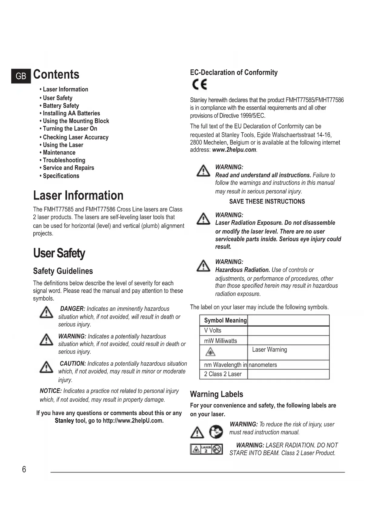
- Turn the laser upside down.
- On the laser, lift up the latch to open the battery compartment cover (Figure B 1).
- Insert four new, high-quality, name brand AA batteries, making sure to position the - and + ends of each battery as noted inside the battery compartment (Figure B 2).
- Push the battery compartment cover down until it snaps in place (Figure ⑧ ③).
- Slide the Power/Transport Lock switch to the right to the Unlocked/ON position (Figure A7).
-
On the keypad (Figure A 4), make sure is green (>5%) . If is red, this means that the battery level is below 5% .
-
The laser may continue to operate for a short time while the battery power continues to drain, but the laser lines will quickly dim.
- After fresh batteries are installed and the laser is turned ON again, the laser lines will return to full brightness.
Whenever the laser is not in use, slide the Power/Transport Lock switch to the LEFT to the Locked/OFF position (Figure A 6) to save battery power.
Turning the Laser On
- Place the laser on a smooth, flat, level surface.
- Slide the Power/Transport Lock switch to the right to the Unlocked/ON position (Figure A7).
- As shown in Figure A 2, press once to display a horizontal laser line, a second time to display a vertical laser line, and a third time to display a horizontal line and a vertical line.
- Check the laser beams. The laser is designed to self-level. If the laser is tilted so much that it cannot self-level (>4^) , the laser beams will continually flash twice and will flash constantly on the keypad (Figure A 3).
-
If the laser beams flash, the laser is not level (or plumb) and should NOT BE USED for determining or marking level or plumb. Try repositioning the laser on a level surface.
-
Press on the keypad to test the Pulse mode. will illuminate on the keypad (Figure A 5) and the laser beams will appear lighter, since they are flashing at a very rapid rate. You will only use Pulse mode with a detector to project the laser beams long range.
7 If ANY of the following statements are TRUE, continue with the instructions for Checking Laser Accuracy BEFORE USING THE LASER for a project. -
This is the first time you are using the laser (in case the laser was exposed to extreme temperatures).
- The laser has not been checked for accuracy in a while.
- The laser may have been dropped.
Checking Laser Accuracy
The laser tools are sealed and calibrated at the factory. It is recommended that you perform an accuracy check prior to using the laser for the first time (in case the laser was exposed to extreme temperatures) and then regularly to ensure the accuracy of your work. When performing any of the accuracy checks listed in this manual, follow these guidelines:
- Use the largest area/distance possible, closest to the operating distance. The greater the area/distance, the easier to measure the accuracy of the laser.
- Place the laser on a smooth, flat, stable surface that is level in both directions.
- Mark the center of the laser beam.
Horizontal Line Accuracy - Level
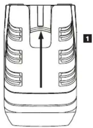
Checking the level of the laser's horizontal line requires a flat vertical surface at least 9m (30') wide.
- Place a tripod at one end of the wall (Figure D①).
- Place the laser on a tripod and screw the threaded knob on the tripod into the female thread on the laser.
- Slide the laser's Power/Transport Lock switch to the right to turn the laser ON (Figure A 7).
- Press once to display a horizontal line.
- Mark two points (P1 and P2) at least 9m (30^) apart along the length of the laser's horizontal line on the wall.
-
Relocate the laser at the other end of the wall and align the laser's horizontal line with point P2 (Figure ①②).
-
Mark point P3 on the laser line near point P1.
- Measure the vertical distance between points P1 and P3.
9 If your measurement is greater than the Allowable Distance Between P1 & P3 for the corresponding Distance Between P1 & P2 in the following table, the laser must be serviced at an authorized service center.
| Distance Between P1 & P2 | Allowable Distance Between P1 and P3 |
| 9m (30') 6mm (1/4") | |
| 12m (40') 8mm (5/16") | |
| 15m (50') 10mm (13/32") |
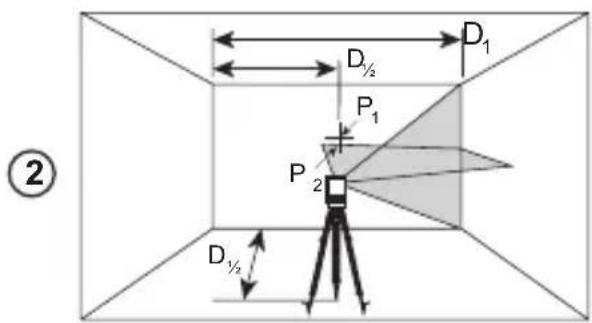
Horizontal Line Accuracy - Tilt
Checking the tilt of the laser's horizontal line requires a flat vertical surface at least 9m (30') wide.
- Place a tripod as shown in Figure E ①, which is:
At the center of the wall (D 1/2).
In front of the wall at a distance of half the size of the wall (D 1/2).
- Place the laser on a tripod and screw the threaded knob on the tripod into the female thread on the laser.
- Slide the laser's Power/Transport Lock switch to the right to turn the laser ON (Figure A 7).
- Press 3 times to display a horizontal line and a vertical line.
- Aim the laser's vertical line at the first corner or reference point (Figure E 1).
- Measure half the distance across the wall (D1 / 2)
- Where the horizontal laser line crosses the halfway point (D1 / 2) , mark point P1.
- Rotate the the tripod so the laser's vertical line is aimed at another corner or reference point (Figure E 2).
- Where the horizontal laser line crosses the halfway point (D1 / 2) , mark point P2.
-
Measure the vertical distance between P1 and P2 (Figure E 3).
-
If your measurement is greater than the Allowable Distance Between P1 & P2 for the corresponding Distance (D1) in the following table, the laser must be serviced at an authorized service center.
| Distance (D1) | Allowable Distance Between P1 and P2 |
| 9m (30') 3mm (1/8") | |
| 12m (40') 4mm (5/32") | |
| 15m (50') 5mm (7/32") | |
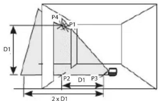
Vertical Line Accuracy - Plumb
Checking the plumb of the laser's vertical line.
- Measure the height of a door jamb (or a reference point on the ceiling) to get height D1 (Figure F 1).
- Place the laser on the floor across from the door jam, (Figure F 1).
- Slide the laser's Power/Transport Lock switch to the right to turn the laser ON (Figure A 7).
- Press twice to display a vertical line.
- Aim the laser's vertical line toward the door jamb or the reference point on the ceiling.
- Where the laser's vertical line meets the height of the door jam, mark point P1.
- From where the laser beam hits the floor, measure the D1 distance and mark it point P2.
- From P2, measure the D1 distance and mark it point P3.
- Move the laser to the opposite side of point P3 and aim the laser's vertical line toward point P2 (Figure F 2).
- Align the laser's vertical line with points P2 and P3 on the floor, and mark point P4 over the door jam.
- Measure the distance between P1 and P4 (Figure F 3).
GB
GB
- If your measurement is greater than the Allowable Distance Between P1 & P4 for the corresponding Vertical Distance (D1) in the following table, the laser must be serviced at an authorized service center.
| Height of Vertical Distance (D1) | Allowable Distance Between P1 and P4 |
| 2.5m (8') 1.5mm | (1/16") |
| 5m (16') 3.0mm | (1/8") |
| 6m (20') 3.6mm | (9/64") |
| 9m (30') 5.5mm | (9/32") |
Using the Laser
Operating Tips
Always mark the center of the beam created by the laser.
- Extreme temperature changes may cause movement of internal parts that can affect accuracy. Check your accuracy often while working.
- If the laser is ever dropped, check to make sure it is still calibrated.
- As long as the laser is properly calibrated, the laser is self-leveling. Each laser is calibrated at the factory to find level as long as it is positioned on a flat surface within average ± 4^ of level. No manual adjustments are required.
- Use the laser on a smooth, flat, level, surface.
Turning the Laser Off
Slide the Power/Transport Lock switch to the OFF/Locked position (Figure A 6) when the laser is not in use. If the switch is not placed in the Locked position, the laser will not turn off.
Using the Laser with Accessories

WARNING:
Since accessories other than those offered by Stanley have not been tested with this laser, use of such accessories with this laser could be hazardous.
Only use Stanley accessories that are recommended for use with this model. Accessories that may be suitable for one laser may create a risk of injury when used with another laser.
The bottom of the laser is equipped with 1/4-20 and 5/8-11 female threads (Figure C) to accommodate current or future Stanley accessories. Only use Stanley accessories specified for use with this laser. Follow the directions included with the accessory.
Recommended accessories for use with this laser are available at extra cost from your local dealer or authorized service center. If you need assistance locating any accessory, please contact your nearest Stanley service center or visit our website: http://www.2helpU.com.
Using the Laser with the L Bracket
Most line lasers that have a 1/4-20 mounting thread can be screwed onto the L Bracket (Figure C). The L Bracket can then be mounted in either of these ways:
- Use its rear magnets against a metal beam.
- Hook its rear screw hole over a nail or screw on a wall.
Maintenance
- When the laser is not in use, clean the exterior parts with a damp cloth, wipe the laser with a soft dry cloth to make sure it is dry, and then store the laser in the kit box provided.
- Although the laser exterior is solvent resistant, NEVER use solvents to clean the laser.
- Do not store the laser at temperatures below -20^ (-5°F) or above 60^ (140°F).
- To maintain the accuracy of your work, check the laser often to make sure it is properly calibrated.
- Calibration checks and other maintenance repairs may be performed by Stanley service centers.
Troubleshooting
The Laser Does Not Turn On
If AA batteries are being used, make sure:
Each battery is installed correctly, according to (+) and (-) listed inside the battery compartment.
- The battery contacts are clean and free of rust or corrosion.
- The batteries are new, high-quality, name brand batteries to reduce the chance of battery leakage.
- Make sure the AA batteries are in proper working condition. If in doubt, try installing new batteries.
- Be sure to keep the laser dry.
- If the laser unit is heated above 50^ ( 120^ ), the unit will not turn ON. If the laser has been stored in extremely hot temperatures, allow it to cool. The laser level will not be damaged by using the Power/Transport Lock switch before cooling to its proper operating temperature.
The Laser Beams Flash
The lasers are designed to self-level up to an average of 4^ in all directions. If the laser is tilted so much that the internal mechanism cannot level itself, the laser beams will flash indicating that the tilt range has been exceeded. THE FLASHING BEAMS CREATED BY THE LASER ARE NOT LEVEL OR PLUMB AND SHOULD NOT BE USED FOR DETERMINING OR MARKING LEVEL OR PLUMB. Try repositioning the laser on a more level surface.
The Laser Beams Will Not Stop Moving
The laser is a precision instrument. Therefore, if it is not positioned on a stable (and motionless) surface, the laser will continue to try to find level. If the beam will not stop moving, try placing the laser on a more stable surface. Also, try to make sure that the surface is relatively flat and level, so that the laser is stable.
Service and Repairs
Note: Disassembling the laser level will void all warranties on the product.
To assure product SAFETY and RELIABILITY, repairs, maintenance and adjustment should be performed by authorized service centers. Service or maintenance performed by unqualified personnel may result in a risk of injury. To locate your nearest Stanley service center, go to http://www.2helpU.com.
GB Specifications
| FMHT77585 FMHT77586 | ||
| Light Source Laser diodes | ||
| Laser Wavelength 630 – 680 nm visible 510 – 530 nm visible | ||
| Laser Power ≤1.3 mW CLASS 2 LASER PRODUCT | ||
| Working Range 20m (65') | 50m (165') with Detector | 30m (100')' 50m (165') with Detector |
| Accuracy ±3 mm per 10 m (±1/8" per 30') | ||
| Power Source 4 AA Alkaline (1.5V) size batteries (6V DC) | ||
| Operating Temperature -10°C to 50°C (14°F to 122°F) | ||
| Storage Temperature -20°C to 60°C (-5°F to 140°F) | ||
| Environmental Water & Dust Resistant to IP54 | ||
Inhalt
| Distance (D1) | Distance admissible Entre P1 et P2 |
| 9 m (30') 3mm (1/8") | |
| 12 m (40') 4mm (5/32") | |
| 15 m (50') 5mm (7/32") | |
Colocar as bacterias AA
Coloque novas bacterias AA no laser FMHT77585 ou FMHT77586.
TYTO POKNY USCHOVEJTE

VAROVÁNÍ:
YctaHObKa 6aTapeek AA
BcTaBbTe HOBbIe 6aTapeKn AA B Ja3ep FMHT77585 nnn FMHT77586.
- IpeBepHnte Ia3ep BBepx HOM.
- CdBnHbTe 3aueKny Ha na3epe, YTo6bl OTkpblkpbIky 6batapeHoro OTOceka (pnc. B 1).
- YCTaHOBInTe YeTbIpe HOBbIE, BBICOKOKaYeCTBeHHbIe MapOuHbIe 6batapeKn AA, co6JIIOJa nOJIpaHocTb - N+, KaK OTMeueHo BHyTpN batapeHoro OTeKa (pnc. B ②).
- HaxMMTe Ha KpbIuKy 6aTapeHoro OTCeka, noka He ycNbblIMTe UeJIyOK (pnc. B 3).
- CdBnHbTe BblKnIouaTeIb NITaHn/6NOKIpOBKn Itna TpaHcnpTIpOBKn BnpaBO, B NOIOKeHne OTKpbITnBKL. (pnc. A 7).
- YbEInTeCb, YTO Ha NaHeIi (pncA 4), TOpNT 3eJIeHbIM (>5%). Ecnn KpacHbI, TO 3TO O3Haaet, YTO 3apRd 6aTaapeek HIXe 5%.
Ja3ep npoJnKHT pa6OtaB B TeueHne KpaTKoro nepNoDa BpemeHn no Mepe pacXoJa 3apraJa 6aTaapeek, Ho JInHn Ja3epa 6ydyT 6bIcTpO TycKHeTb.
-ПослеЗамeньбатapeekHaHOBbIиВКИчЕнЯla3epa, noJIhaяркoctBJINHINJa3epaBOCCTaHOBNTcR.
7 EcnnIa3ep He nCIOJIb3yeTc, CdBnHbTe BbIKIooYateIb IITaHn/6JOKIpOBKn DnI TpaHCnOpTIPOBKn BJIEBO B noIOXeHne 6JOKIpOBKn/BbIKI. (pnc. A 6), YTo6bl He paXoIOBaTb 3apId 6aTaapeek.
Вклоченье Лазера
1 UcTaHOBnTe Ia3ep Ha IpaIkyIO, IIocKyIO nPoBHyIO NOBepXHOCTb.
2. CdBnBte BbIKIOuATEJIb NITaHIN/6IOKIpOBKn IJRA TpaHCnOpTnOpBKn BnpaBO, B NOIOKeHne OTKpbITN/BCJI. (pnc. A ⑦).
3. KaB vIaHn 13 pnc. A 2, OJHO HaxKaTne BJIIOUcaET OTO6paXeHne TOpN3OHTaJIbHOJ LInHM JIA3epa, BTOpoe HaxKATne BKIOUaEe OTo6paXeHne BepTKaJIbHOJ LInHM JIA3epa, TpeTbe HaxKATne BKIOUaEe OTo6paXeHne TOpN3OHTaJIbHOJ BepTKaJIbHOJ LInHM.
4.Проверълалерьллун.лалерochaшenKOMпсатормдяcamOBbipabHnBaHn.ЕсилалернaknohenHactoNBkoCINьHO,TO He MoKet BblpoBHrBcR cam (>4^) ,TOлалерьллунБуdHTperyIaRHO MIRaTdbaXdbI,aHa naHelen6ydTeNOCTOHHMOIraTb(PNC.A③)
5. Ecπn Ja3epHbIe lyHmMraHOT, To Ja3ep He rOpN3OHTaJIeH (nHn BepTnKanE) n HE IOnJXEH nCnONb3ObaTbcS nIg OnpedEnHn Hn MapKnPOBn yPOBH nIh OTBeCa. POnpO6yIte nepeCTabITb Ja3ep Ha rOpN3OHTaIbHyo NOBepxHOCTb.
6. Haxmte Ha naHenn, YTObI NCbITb MMnylbChbI peKIM. Ha naHenn 3arOpITc (pnc. A5) nJa3epHbIe IyN 6byT BByrJIaTe bCBETIe, TAK KAK OHN 6byT MIRATb C BbICOKO qACTOTOn. IMnylbChbI peKIM cNeJyET npIMHeYb TOBko C DeTEKTopOM dIra IpoeuropOBaHn JIA3epHBIX JIyey Ha 6oJIbwoe pacCTOHaHE.
7. Ecn KAKNE-JIbO n3 HnKeepnBeHbIx yTbeKdEHN BEPHbl, cndyTe INcTpkyLmNo Ipoeepke moHocmu na3epa IPEPD NcNOJb3OBAHNEM JIA3EPBA paboTe.
CdbraTe BbIKHouaTeNb NtTaHn/6NOKpOBKn DnTpaHCnOpTnpOBKn B noJIOKeHne BbIKJ./6NOKpOBKn (pnc.
A6),ecnIa3ep He nCnoJb3yeTc. EcnBbIKIOuateNb He yCTaHOBNTb B NOIOXeHHe 6JIOKIpOBKn,TO Na3ep He BBIKIOUHTcR.
IcnoJb3OBaHne Ia3epa CdoONHHTeJIbHbIMN npHaJExKHOCTaMn

OCTOPOXHO:
B c83u c mem, ymo dononHumeNBhe npunadnexhocmu dpyux npou3oodumeneu nomumo Stanley he npoxodun npoepky ha coBmecmumocmb c daHHbIM u3deJeM, ux ucnoIb30BaHue MOxem npedcmaeJmb onachocmb.
Ucnonb3yume monbko npuhaednexHocmu Stanley, pekomehdoeAHhie dny u cnonb3o6aHua c daHou modenb. DononHumenbHie npuhaednexHocmu, npu2oDhie dny odHou naepHo ycmaHOKu, moaym npedcmaBnMb onachocmb u npubecmu K mpaBme npu u cnonb3o6aHuu dny dpyeOu naepHo ycmaHOKu.
HnKnaCTb na3epa Ochaue HByTpeneHnepe3b6o1 1/4-20 n5/8-11 (pnc. B) dna 3akpenneHnre Tekyuux nn 6dyuNX doonHntbHbix npHaadnxHocte Stanley. NcnoJb3ynt ToJbKO npHaadnxHocTn Stanley, npedna3NaueHHbIe dna NCNOJb3OBaHnC daHHbIM na3epom. CneNyTe INHCTpykUmaB BXODaUM B KOMNKeT NOCTaBKn PnHaadNxHocTn.
DOnonHnTeNbHbIe npHaadNexKHOCTn, peKOMeHNoDaBHbIe K NcNoJIb3OBaHmO C DaHHbIM Ja3epOM, MoXHO pPNO6peCTn 3a OTdeJIbHyIO PnATy y BaWero DnIepa NIn B 6nIXKaIWe m cepBnCHOM cHTpe. EcIN Bam HxKHa NMOUcB pPn NOnCke KaKoI-Jn6o npHaadNexKHOCTn, CBxNITecb C 6nIXKaIWM cepBnCHbIM cHTpOM Stanley nIN NoCeTNTe HaI Be6-caIT: http://www.2helpU.com.
IcnoJb3ObaHne L-06pa3Horo KpoHwTeHa
L-6pa3HbI KPOHHTeHH MoKeT npMHeTbcra C na3epOM FMHT77585/ FMHT77586 (pnc. B) L-6pa3HbI KPOHTeHH OchauSeH BHeUHeN pe3b6o1 1/4-20 dny KpePnEHH na3epa, a TaKke MaHHTaMn N OTBepCTnem dny nOdBWeuBaHH na3epa Ha cTeHy.
TexHnueckoe o6cnyxmbaHne
- Ecnn Ja3ep He nCNOJb3yeTc, ONUCTnTE BHeuHne YaCTN BnaXHo TKAHbIO IN PPOTpIe Ja3ep CyXoMRAKo TKaHbIO, YTO6bl NOnHOCTbIO eRO BbICyUHTb, NOcNe Yero NoJIOxNTe eRO B RAUNK, NOCTaBnEHHbI B KOMPJIeKTe.
-
Kopnyc na3epa yctoynuB K pactbOpnteJAM, HO TEM He MeHee, HIKOgDA He nCnoNb3yIte pactbOpnteJIN dnn YnCTKN na3epa.
-
He xpaHnTe Ia3ep npn Tempepatype Hxke -20°C (-5°F) nnn Bblse 60°C (140°F).
Дя подерханя точно pa6otbl,perylnarpo npOBepaTe kaINbpoBky na3epa. - PpOBePKa KaIN6pOBky, a TaKKe TexHnueckoe 06cJyKnBaHne n peMOHT MOxHO BbINOHNtB C cepBnchbix ueHtpax Stanley.
HencnpabHoctn n cnocobn x yctpaHeHna
Ja3ep He BkIIOUaETcA
-ПиИСПОЛБЗOBAHIN6БатAPEEK AA y6eДNTeCb,чTO:
Kazda 6atapeKa npaBnBHO BCTaBHeA, cornaCHO mapKnpoBKe (+) n(-) BHTpu 6atapeHoro OTeka.
- KoHTaKTbI 6aTapeeK YnCTbI e N 6e3 npn3HaKOB pKaBcHbI nn Koppo3nn.
BatapeKn YBJIOTcHOBbIMN, BbICOKO KaHeCTBa n MapoHbIMN, YTO6bl CHN3NTb pNC yTeKN.
- Y6eINTecb, yTO 6aTapeKn AA haxoJrTcB pa6ooyem COCTOHN. Pn HAnuHm ComHeH, nonpOByTe yCTaHOBNTb HOBBe 6aTapeKn.
-Деркinte na3ep cyxIM.
- Ecni Ja3ep HarpeT do Bblwe 50 °C (120 °F), to yctpoiCTBO He BKIOHHTc. Ecni Ja3ep XpaHnIc npn KpaHne BbICOKOI TemnepaType, no3BOJbTe emy octbITb. Ja3epHbI HNBENrP He bdyet nobpekJeH, ecni erO BbIKIOuHaTeJI PtAnH/ 6LOKIPOBKn dIra TpaHCnOpTIpOBKn IcNOB3OBaTb Do oxlaXdEHHdo pa6OeH TemnepaTypbl.
Ja3epHbIe LyuN MmraIoT
KoHCTpyKuIy Ia3epa npEydCMatpnaeT cMoBbipabHBnBaHne do 4^ BcpeHem BO BCEx HappaBHeNix. EcnI Ja3ep HaKnHOHe HAcToIbKO CInIbHO, YTO BHyTppeHHM MexAHn3M He MoKeT erO BbIPOBHrT, To Ja3epHbI JyUHa HauHyT MIRaTb, yKa3bIBaHa nPpeBbIeHne DmAna3OHa HaKnOHa. MIRAOUINE JIA3EPHbIE JyUH HE RABJIOTCRIOPN3OHTAIBHbIMN INIIN BEPTIKALbHbIMN INHE OJIXHbI NCIOJIb3OBATbcra dIg ONPeDJIeHn ININ MAPKNPOBKN YPOBHry ININ OTBECA. Noppo6ynte nepectabIT Ja3ep Ha 6oJee rOp3OHTaNbHyIO NobepXHOCTb.
Ja3epHbIe IyuH He IpeKpaaIoT DnRaTbcS
Ja3ep RaJIaTeCB BaICOKOTOHbIM INHCTpyMeHTOM. N03TOMy, ecn erO He paCNOJIOXHTb Ha yCToYHBOB (N HEnoDBNKHO) NOBepxHocTb, To Ja3ep 6yDet nOCToAHNo bITaTbcr OnpdeIInTB yPOBeHb. Ecn IyU He npeKpaAaet DBNATbCra, nonpO6yIte YCTaHOBt JAp3ep Ha 6OJee yCToYHByIO NOBepxHocTb. TaKKe nOcTaPauTEcb y6eINTbcra, YTO NOBepxHocTb OTHCINTeMbHO NIOCKaR INROPn3OHTaJIbHa, YTO6bl ObecneuHT cbA6NJbHOCTb Ja3epa.
06cnyxnbHne npemOH
Ppumeyaue: Pa36opka nasepnoo Hueenupa anHynupyema aapaHmio Ha u3denue.
YTo6bI o6ecneuHb B63O1ACHOCTb n HADEXKHOCTb pa60bI yctpOiCTBa, pemOH, 6cbNyXnBaHne n peyInpOBky cJeDyET npBOoNTB B aBTOpN3OBAHHbIX cepBnCHbIX ceHTpax. TexHnueCKoe 6cbNyXnBAHne, BblONJIHeHHoe HEKBaINΦnUPOBaHHbIMn JInCaMn, MoKeT CO3dA Tb pNCK IOnyehn TpaBM. YTo6bI hAIITN 6bnKaIIm CepBnCHbI ueHTp Stanley, nocTeTIte http://www.2helpU.com.
TexHnueckne xapaKTepeNCTnKN
TIETO POKYNY USCHOVAJTE

VAROVANIE:
Expozicia laserovym ziarenim. Laserovu vodovahu nerozoberajte ani ju nemodifikujte.Vo vnutri sa nenachadzaju ziadne diely, ktoré by si použivatel'mohol opravit'svojpomocne.Mohlo by dojst' zavaznému poskodeniu zraku.

VAROVANIE:
N3KJIIOUyBaHe Ha Ja3epa
ПлбзHeTe 3akIIOUbaIиnpeBJIIOUbATEn 3a3axpaHbaHe/ Ппснoc ha N3KЛ./3akIIOUeHa no3uIgna(ФИура A6)KORAto Na3epa He e b ynoTppe6a.AkO npEbkIIOUbATEn He e nocTaBeH B 3akIIOUeHa no3uIgna, na3epa Hma da ce n3KlIOUH.
I3noJ3BaHe Ha Ia3epa c DonbHnTeHn npncnoc6JIeHn

NPEyUNPEKDEHNE:
HnHexe c mo3u uHcmpymHe ca mecmbaHu akcecoapu, pa3nUHu om npednoKeHume om Stanley, u3noJ3eaHemo Ha makuea akcecoapu c mo3u na3ep Moke da e onacho.
I3non3eaumc amo Stanley akcecoapu, npenopbuahu 3a ynompeba c mozu moden. Akcecoapu, koumo moxe da ca nodxodrau 3a eunn na3ep, moxe da cb3dadam puck om HapaHaahe, kozamo ce u3non36am c dpyz na3ep.
Доннастара на ласяе о obopyдва с 1/4-20 n 5/8-11 Женда pe3бовka (Фигра B) за постаяну на Habсторцу n 6ьдец akcecoари на Stanley. Изоллайтсамо Stanley akcecoари сецално 3a уnotpe6a с тозnlазр. Следыт упьтванята, кОТTO ИДВATС Akcecoapa.
Ha pa3noJooJeHne ca akcecoapn 3a ynoTpe6a c To3n
Ia3ep CpeuDOnbHInTeHNO 3aIIaUae He OT BaWnMecTeH
PpeCTabHTe IINy YbHHomOoE H cepBn3e HcHTbp.AKO
IMate Hxka ot NOMO3a HAMIPAHe Ha NOxOJaIakcecoap,
MOJI, CBpKxeTe Ce c HAI-6JIIN3KmC cepBn3e HcHTbp Ha
Stanley INNI OTnDETe Ha:http://www.2helpU.com.
N3nOJ3BaHe Ha L cKo6aTa
L cko6ata moke da ce n3non3Ba c na3epn FMHT77585/ FMHT77586 (Fmrypa B). L cko6ata mma 1/4-20Mbxxka pe36obKa, KbM KOrTO ce npKauBa Jna3epa, N MaHHTnte iKnOHa/dynkata 3a OKaUbaHe Ha Jna3epa KbM CTeHa.
PoiapbKka
Korato na3epa He e b ynoTpe6a, noocTeTe BbHnHnTe Yactn c MOKpa Kbpna, n36bpwe Te na3epa c Meka Kbpna, 3a Da cTe cnrypHn, ye e cyx, n CneI TOBa r cBxpanHe T B npedocTaBeHaTa Kytn.
Bbnpekn, Ye BbHnHaTa YacT Ha Ja3epa e ycToMnBa Ha pa3TbOpn, HNKOTA He n3noJ3BaIte npenapatn 3a nouchTbaHe Ha Ja3epa.
- He cxbxaHbAaTe Ia3epa npI TeMnpepaTpa noI -20 ^ C (-5F) nII nHa 60 ^ C (140 F).
3a da ocinrypnte touhoctta ha Baata pa6ota, cheTo npOBepaBaiTeIa3epa 3a npaBnHa KaIIbpaun.
- Пюверки на калбрацята и дугни поравки, сбьрзни с подрьжкata може за се ИЗБьршатВ сервиЗнITE цentpoBE ha Stanley.
OnpaBXeHa npo6JIeMn
Ia3epbT He ce BkIIOUyBa
- Ako n3no3BaTe AA 6aTepuInTe, yBepTe ce, ye:
Bcya6baTePnE nocTaBeHa npaBnHIO, cnopei (+) n(-) yka3aHbBtpe BOTDeJeHHeTo 3a 6aTePnnte.
- BaTePmHHTe KOHTaKTn Ca YIcTn N HЯMaT pBxJaN KOpO3n.
- BaTePnIte ca HOBn, BnCOKOKaYeCTBeHn, OT YTBbPdHa MapKa, 3a HamaJIbaHe Ha 7aHca 3a N3TuHaHe Ha 6aTePnIte.
- YBepTe ce, Ye AA 6aTePnnte ca B NOxOJaPo paOtho cbCToHHe. Ako mATE cbMHeHne, NoCTaBeTe HOBn 6aTePnN.
BnHaI NoIpbXaIe JIa3epa cyx. - Ako na3epnHrT ypeE harpT n4 50 °C (120 °F), ypeBt Hma Da ce BkIIOUH. Ako na3epbTe cxbpaHraBaH npn N3KIIIOHTeJIHO ropeua Tempeatypa, octabeTe rda Ce oxnaDi. Na3epHOTo HNBO Hma Da ce NobpeDn OT N3NoI3BaHeTo Ha 3akNIOUbaUnia ppeBkIOUcBaTeI 3a 3axpaHBAhe/ PpeHoc., npdei Da ce oxnaDi nO HopMaJIHaTa cn pa6oTHa Tempepatya.
Ja3epHnTe IbU npncBETBaT
Ja3epnTe ca cb3daeHn 3a caMOHNBeIpaHne Do cpeHNO 4^ BbB BCnKn IocKn. Ako Ja3epbT ce HaKIOH TOIKOBA MHoro, Ye BbTpEHHNt MExAHN3bM da He MOKe Da ce CaMOHNBEIpa, Ja3epHnTe JbUe Nc IpOCBETBaT, Yka3BaKn, Ye oxbaTaHa Na KaIOHa 6bJe npEBuWeH. PIPNCBETBAUITE JbU, Cb3DAEHN OT JIA3EPA HE CA NOJERATIN INIOTBECHN IN HE TPR5BA DA CE IN3IOJ3BAT 3A NOTBbPjDABAHEN IIIN OT6EJIra3BAHE NOJERATO INIOTBECHO. OInTaIte Ce da CMeHnTe MAcTOTO Ha Ja3epa Ha no-pabHa NOBbpxHOCT.
Ia3epHnte IbUHЯMa Da cnpaT da ce DvIXkaT
Ia3epbTe Ipeu3eH INcHcTpymENT. CneIOBaTeJnHO, aKO He e NOCTaBeH Ha cTa6uINHa (I HEnoDBrXkHa) NOBbPxHOCT, Ia3epbT Ie npOblxN da ce ONITBa Da HAMEp N3paBHBaHe. Ako IIbYbT He cnpe Da ce MeCTN, ONITaTe Da NOCTaBNTe Ia3epa Ha No-CTa6uINHa NOBbPxHOCT. CbIo Taka, ONITaTe ce Da ce yBepTe, Ye NobbpxHOCTTa e OTHOCHTJIHO Pnocka n paBHa, taka Ye Ia3epbT Da e cTa6uJIneH.
CepBn3npaHe n nonpaBka
3a6eKka: Pa2aNo6eaHemo Ha na3epa uce anyIupa ecu4ku aapaunuHa npodykma.
3a da ocirypnte 5E3OPIACHOCT n HADEXHIOCT ha npodykta, nonpabkaeta, nodpbkkata n peylnpaheTo Tpr6ba da ce n3BpbwBA B yIbJNHOOMOeHN cepBN3HN ueHTPOBE Ha Stanley. CepBn3npaHe nnnoPdpbKka, KOINTo ce n3BbpWBAT OT HeKBaINΦnCIPan nepcoHaJI MOKe Da doBeJe Do HapaHBAHn. 3a da hameptte Na-6JIIM3KNrT Do BaC cepBn3eH ueHTbp Ha, OTndeHa http://www.2helpU.com.
Cneunfkaun
© 2018 Stanley Black & Decker
N612157 September 2018