
FatMax FMHT1-77442 - Hand tool STANLEY - Free user manual and instructions
Find the device manual for free FatMax FMHT1-77442 STANLEY in PDF.


| Product Type | 5-point and cross-line laser level |
| Brand | Stanley |
| Model | FatMax FMHT1-77442 |
| Light Source | Laser diodes |
| Laser Class | 2 (IEC 60825-1:2014) |
| Laser Power | ≤ 1.0 mW |
| Wavelength | 510 - 530 nm (visible green) |
| Accuracy (lines and points except bottom point) | ± 3 mm / 10 m (± 1/8" / 30') |
| Bottom point accuracy | ± 6 mm / 10 m (± 1/4" / 30') |
| Working range without detector | 20 m (65') |
| Working range with detector | 50 m (165') |
| Automatic leveling | Up to 4° tilt |
| Beam types | Horizontal line, vertical line, 5 points (up, down, front, right, left) |
| Pulse mode | Yes (for use with detector) |
| Power supply | 4 AA 1.5 V batteries (alkaline) or 4 AA Ni-MH 1.2 V batteries (rechargeable) |
| Operating temperature | -10 °C to 50 °C (14 °F to 122 °F) |
| Storage temperature | -20 °C to 60 °C (-5 °F to 140 °F) |
| Protection rating | IP54 (water and dust resistant) |
| Mounting | Integrated magnets, 1/4-20 and 5/8-11 threaded holes, sliding block |
| Optional accessories | Multi-function mount FMHT77435, tripod, detector |
| Maintenance | Clean with a damp cloth, do not use solvents |
| Safety | Class 2 laser product, do not stare into beam, avoid eye exposure |
| Repairs | Repairs by authorized service center only |
| Warranty | Not specified |
Frequently Asked Questions - FatMax FMHT1-77442 STANLEY
User questions about FatMax FMHT1-77442 STANLEY
0 question about this device. Answer the ones you know or ask your own.
Ask a new question about this device
Download the instructions for your Hand tool in PDF format for free! Find your manual FatMax FMHT1-77442 - STANLEY and take your electronic device back in hand. On this page are published all the documents necessary for the use of your device. FatMax FMHT1-77442 by STANLEY.
USER MANUAL FatMax FMHT1-77442 STANLEY
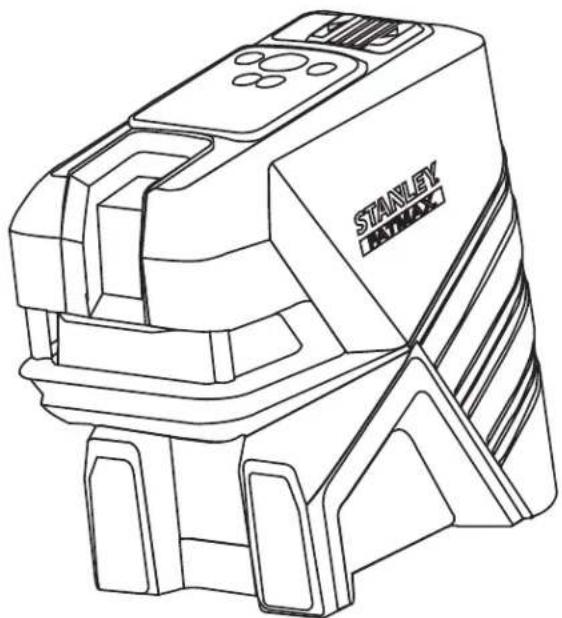
Self-Leveling 5-Dot Cross Line Laser
natural_image
Line drawing of a Stanley Haymax industrial machine (no text or symbols on the diagram itself)www.2helpU.com



Please read these instructions before operating the product.
flowchart
graph TD
    A["3a"] --> B["STANLEY"]
    B --> C["③"]
    C --> D["①"]
    D --> E["②"]
    E --> F["③c"]
    F --> G["③b"]
    G --> H["③d"]
    H --> I["③c"]
    I --> J["③a"]
    style A fill:#f9f,stroke:#333
    style B fill:#ccf,stroke:#333
    style C fill:#cfc,stroke:#333
    style D fill:#fcc,stroke:#333
    style E fill:#cff,stroke:#333
    style F fill:#ffc,stroke:#333
    style G fill:#fcf,stroke:#333
    style H fill:#cff,stroke:#333
    style I fill:#ffc,stroke:#333
    style J fill:#cfc,stroke:#333
©
natural_image
Technical line drawing of a mechanical component with no visible text or symbols

D

natural_image
Technical line drawing of a mechanical device with no visible text or symbols
natural_image
Technical line drawing of a mechanical device with no visible text or symbolsE


Figures
F
①

②

③

G
①

②
③
H

I
1

②

K

natural_image
Technical line drawing of a mechanical clamp or bracket assembly (no text or symbols)J
①

②

③

④
GB
Contents
- Laser Information
- User Safety
- Battery Safety
• Installing AA Batteries
• Using the Mounting Block - Turning the Laser On
- Checking Laser Accuracy
• Using the Laser - Maintenance
- Troubleshooting
• Service and Repairs - Specifications
Laser Information
The FMHT1-77415 and FMHT1-77442 5 Dot Cross Line lasers are Class 2 laser products. The lasers are self-leveling laser tools that can be used for horizontal (level) and vertical (plumb) alignment projects.
User Safety
Safety Guidelines
The definitions below describe the level of severity for each signal word. Please read the manual and pay attention to these symbols.

DANGER: Indicates an imminently hazardous situation which, if not avoided, will result in death or serious injury.

WARNING: Indicates a potentially hazardous situation which, if not avoided, could result in death or serious injury.

CAUTION: Indicates a potentially hazardous situation which, if not avoided, may result in minor or moderate injury.
NOTICE: Indicates a practice not related to personal injury which, if not avoided, may result in property damage.
If you have any questions or comments about this or any Stanley tool, go to http://www.2helpU.com.

WARNING:
Read and understand all instructions. Failure to follow the warnings and instructions in this manual may result in serious personal injury.
SAVE THESE INSTRUCTIONS

WARNING:
Laser Radiation Exposure. Do not disassemble or modify the laser level. There are no user serviceable parts inside. Serious eye injury could result.

WARNING:
Hazardous Radiation. Use of controls or adjustments, or performance of procedures, other than those specified herein may result in hazardous radiation exposure.
The label on your laser may include the following symbols.
| Symbol Meaning | |
| V Volts | |
| mW Milliwatts | |
| Laser Warning | |
| nm Wavelength in | nanometers |
| 2 Class 2 Laser |
Warning Labels
For your convenience and safety, the following labels are on your laser.

WARNING: To reduce the risk of injury, user must read instruction manual.
WARNING: LASER RADIATION. DO NOT STARE INTO BEAM. Class 2 Laser Product.


- Do not operate the laser in explosive atmospheres, such as in the presence of flammable liquids, gases, or dust. This tool may create sparks which may ignite the dust or fumes.
- Store an idle laser out of reach of children and other untrained persons. Lasers are dangerous in the hands of untrained users.
- Tool service MUST be performed by qualified repair personnel. Service or maintenance performed by unqualified personnel may result in injury. To locate your nearest Stanley service center go to http://www.2helpU.com.
- Do not use optical tools such as a telescope or transit to view the laser beam. Serious eye injury could result.
- Do not place the laser in a position which may cause anyone to intentionally or unintentionally stare into the laser beam. Serious eye injury could result.
- Do not position the laser near a reflective surface which may reflect the laser beam toward anyone's eyes. Serious eye injury could result.
- Turn the laser off when it is not in use. Leaving the laser on increases the risk of staring into the laser beam.
- Do not modify the laser in any way. Modifying the tool may result in hazardous laser radiation exposure.
- Do not operate the laser around children or allow children to operate the laser. Serious eye injury may result.
- Do not remove or deface warning labels. If labels are removed, the user or others may inadvertently expose themselves to radiation.
- Position the laser securely on a level surface. If the laser falls, damage to the laser or serious injury could result.
Personal Safety
- Stay alert, watch what you are doing, and use common sense when operating the laser. Do not use the laser when you are tired or under the influence of drugs, alcohol, or medication. A moment of inattention while operating the laser may result in serious personal injury.
- Use personal protective equipment. Always wear eye protection. Depending on the work conditions, wearing protective equipment such as a dust mask, non-skid safety shoes, hard hat, and hearing protection will reduce personal injury.
Tool Use and Care
- Do not use the laser if the Power/Transport Lock switch does not turn the laser on or off. Any tool that cannot be controlled with the switch is dangerous and must be repaired.
- Follow instructions in the Maintenance section of this manual. Use of unauthorized parts or failure to follow Maintenance instructions may create a risk of electric shock or injury.
Battery Safety

WARNING: Batteries can explode, or leak, and can cause injury or fire. To reduce this risk:
- Carefully follow all instructions and warnings on the battery label and package.
- Always insert batteries correctly with regard to polarity (+ and -), as marked on the battery and the equipment.
- Do not short battery terminals.
- Do not charge disposable batteries.
- Do not mix old and new batteries. Replace all batteries at the same time with new batteries of the same brand and type.
- Remove dead batteries immediately and dispose of per local codes.
- Do not dispose of batteries in fire.
- Keep batteries out of reach of children.
- Remove batteries when the device is not in use.
Installing AA Batteries
Load new AA batteries in the FMHT1-77415 or FMHT1-77442 laser. In the FMHT1-77442 laser you can also load AA rechargeable batteries. When using rechargeable batteries, refer to the Stanley FatMax FMHT80690 Charger Manual.
- Turn the laser upside down.
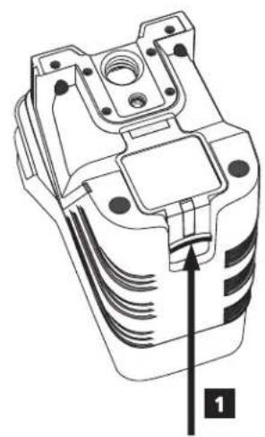
- On the laser, lift up the latch to open the battery compartment cover (Figure © #1).
- Insert four new, high-quality, name brand AA batteries, making sure to position the - and + ends of each battery as noted inside the battery compartment (Figure © #2).
GB
- Push the battery compartment cover down until it snaps in place (Figure © #3).
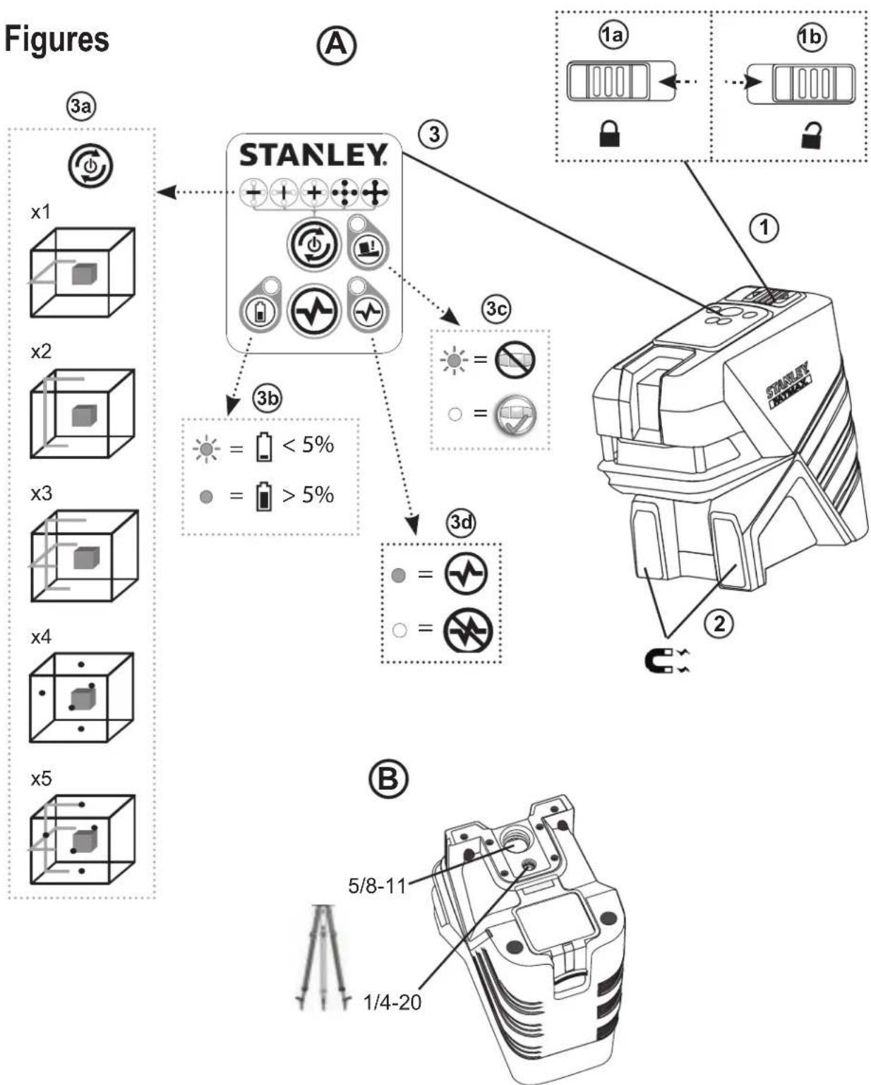
- Slide the Power/Transport Lock switch to the right to the Unlocked/ON position (Figure Ⓐ #1b).
-
On the keypad (Figure A #3b), make sure is green (> 5%). If as red, this means that the battery level is below 5%.
-
The laser may continue to operate for a short time while the battery power continues to drain, but the laser lines and dots will quickly dim.
-
After fresh batteries are installed and the laser is turned ON again, the laser lines and dots will return to full brightness.
-
When the laser is not in use, slide the Power/Transport Lock switch to the LEFT to the Locked/OFF position (Figure A #1a) to save battery power.
Using the Mounting Block
On the bottom of the laser is a moveable block (Figure D).
- To use the magnets on the front of the laser (Figure A #2) to mount the laser against the side of a steel beam, do not extend the moveable block (Figure D #1). This will allow the down dot to be aligned with the edge of the steel beam.
- To mount the laser over a point on the floor (using a multifunction bracket or a tripod), pull out the moveable block until it clicks in place (Figure①#2). This will allow the laser down dot to display through the 5/8-11 mounting hole and the laser to be rotated over the 5/8-11 mounting hole without moving the vertical position of the laser.
Turning the Laser On
- Place the laser on a smooth, flat, level surface.
- Slide the Power/Transport Lock switch to the right to the Unlocked/ON position (Figure Ⓐ #1b).
-
As shown in Figure A #3a, press once to display a horizontal laser line, a second time to display a vertical laser line, a third time to display a horizontal line and a vertical line, a fourth time to display 5 dots, and a fifth time to display the horizontal and vertical lines with the 5 dots.
-
Check the laser beams. The laser is designed to self-level. If the laser is tilted so much that it cannot self-level ( >4^ ), the laser beams will continually flash twice and will flash constantly on the keypad (Figure A #3c).
- If the laser beams flash, the laser is not level (or plumb) and should NOT BE USED for determining or marking level or plumb. Try repositioning the laser on a level surface.
- Press 📂 on the keypad to test the Pulse mode. will illuminate on the keypad (Figure Ⓐ #3d) and the laser beams will appear lighter, since they are flashing at a very rapid rate. You will only use Pulse mode with a detector to project the laser beams long range.
-
If ANY of the following statements are TRUE, continue with the instructions for Checking Laser Accuracy BEFORE USING THE LASER for a project.
-
This is the first time you are using the laser (in case the laser was exposed to extreme temperatures).
- The laser has not been checked for accuracy in a while.
• The laser may have been dropped.
Checking Laser Accuracy
The laser tools are sealed and calibrated at the factory. It is recommended that you perform an accuracy check prior to using the laser for the first time (in case the laser was exposed to extreme temperatures) and then regularly to ensure the accuracy of your work. When performing any of the accuracy checks listed in this manual, follow these guidelines:
- Use the largest area/distance possible, closest to the operating distance. The greater the area/distance, the easier to measure the accuracy of the laser.
- Place the laser on a smooth, flat, stable surface that is level in both directions.
• Mark the center of the laser beam.
Horizontal Line Accuracy - Tilt
Checking the tilt of the laser's horizontal line requires a flat vertical surface at least 30' (9m) wide.
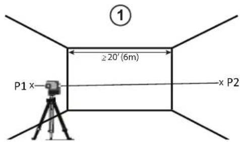
- Place the laser as shown in Figure ⑤ #1 and turn the laser ON.
-
Press ③ times to display a horizontal line and a vertical line.
-
Aim the laser's vertical line at the first corner or reference point (Figure F#1).
- Measure half the distance across the wall (D1/2) (Figure F #1).
- Where the horizontal laser line crosses the halfway point (D1/2), mark point P1 (Figure F #1).
- Rotate the laser to another corner or reference point (Figure F #2).
- Where the horizontal laser line crosses the halfway point (D1/2), mark point P2 (Figure F #2).
- Measure the vertical distance between P1 and P2 (Figure F #3).
- If your measurement is greater than the Allowable Distance Between P1 & P2 for the corresponding Distance (D1) in the following table, the laser must be serviced at an authorized service center.
| Distance (D1) | Allowable Distance Between P1 and P2 |
| 9 m (30') 3 mm (1/8") | |
| 12 m (40') 4 mm (5/32") | |
| 15 m (50') 5 mm (7/32") | |
Horizontal Line Accuracy - Level
Checking the level of the laser's horizontal line requires a flat vertical surface at least 30' (9 m) wide.
- Place the laser at one end of the wall as shown in Figure ⑤ #1, and turn the laser ON.
- Press 📋 once to display a horizontal line.
- Mark two points (P1 and P2) at least 30' (9 m) apart along the length of the laser's horizontal line on the wall (Figure E #1).
- Relocate the laser at the other end of the wall and align the laser's horizontal line with point P2 (Figure E #2).
- Mark point P3 on the laser line near point P1 (Figure E #2).
-
Measure the vertical distance between points P1 and P3 (Figure E #2).
-
If your measurement is greater than the Allowable Distance Between P1 & P3 for the corresponding Distance Between P1 & P2 in the following table, the laser must be serviced at an authorized service center.
| Distance Between P1 & P2 | Allowable Distance Between P1 and P3 |
| 9 m (30') 6 mm (1/4") | |
| 12 m (40') 8 mm (5/16") | |
| 15 m (50') 10 mm (13/32") | |
GB
Vertical Line Accuracy - Plumb
Checking the plumb of the laser's vertical line.
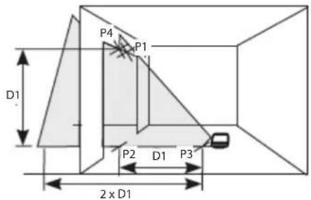
- Measure the height of a door jamb (or a reference point on the ceiling) to get height D1 (Figure G #1).
- Place the laser as shown in Figure G #1 and turn the laser ON.
- Press twice to display a vertical line.
- Aim the laser's vertical line toward the door jamb or the reference point on the ceiling (Figure G #1).
- Mark points P1, P2, and P3, as shown in Figure Ⓖ #1.
- Move the laser to the opposite side of point P3 and aim the laser's vertical line toward point P2 (Figure G #2).
- Align the vertical line with points P2 and P3, and mark point P4 (Figure ⑤ #2).
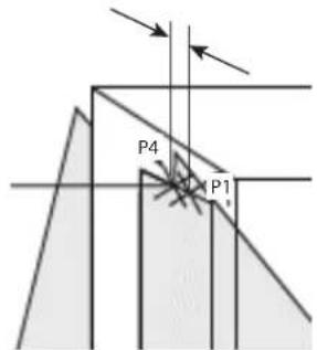
- Measure the distance between P1 and P4 (Figure Ⓖ #3).
9 If your measurement is greater than the Allowable Distance Between P1 & P4 for the corresponding Vertical Distance (D1) in the following table, the laser must be serviced at an authorized service center.
| Height of Vertical Distance (D1) | Allowable Distance Between P1 and P4 |
| 2.5 m (8') 1.5 mm (1/16") | |
| 5 m (16') 3.0 mm (1/8") | |
| 6 m (20') 3.6 mm (9/64") | |
| 9 m (30') 5.5 mm (9/32") | |
GB
Plumb Dot Accuracy
Checking the plumb calibration of the laser can be most accurately done when there is a substantial amount of vertical height available, ideally 25' (7.5 m), with one person on the floor positioning the laser and another person near a ceiling to mark the dot created by the beam on the ceiling.
- Mark point P1 on the floor (Figure ① #1).
- Turn the laser ON and press ④ times to display dots above, ahead, below, and to the right and left of the laser.
- Place the laser so that the down dot is centered over point P1 and mark the center of the up dot on the ceiling as point P2 (Figure ① #1).
-
Turn the laser 180°, making sure that the down dot is still centered on point P1 on the floor (Figure ① #2).
-
Mark the center of the up dot on the ceiling as point P3 (Figure ① #2).
-
Measure the distance between points P2 and P3.
-
If your measurement is greater than the Allowable Distance Between P2 & P3 for the corresponding Distance Between Ceiling & Floor in the following table, the laser must be serviced at an authorized service center.
| Distance Between Ceiling & Floor | Allowable Distance Between P2 & P3 |
| 4.5 m (15') 3 mm (1/8") | |
| 6 m (20') 4.2 mm (5/32") | |
| 9 m (30') 6 mm (1/4") | |
| 12 m (40') 8.4 mm (5/16") | |
Level Dot Accuracy - Level
Checking the level calibration of the laser unit requires two parallel walls at least 20' (6 m) apart.
- Turn the laser ON and press ④ times to display dots above, ahead, below, and to the right and left of the laser.
- Place the laser 2"-3" (5-8 cm) from the first wall. To test the front laser dot, make sure the front of the laser is facing the wall (Figure H #1).
-
Mark the laser dot position on the first wall as point P1 (Figure H #1).
-
Turn the laser 180° and mark the laser dot position on the second wall as point P2 (Figure Ⓗ #1).
- Place the laser 2"-3" (5-8 cm) from the second wall. To test the front laser dot, make sure the front of the laser is facing the wall (Figure H#2), and adjust the height of the laser until the laser dot hits point P2.
- Turn the laser 180^ and aim the laser dot near point P1 on the first wall, and mark point P3 (Figure H #2).
- Measure the vertical distance between points P1 and P3 on the first wall.
- If your measurement is greater than the Allowable Distance Between P1 & P3 for the corresponding Distance Between Walls in the following table, the laser must be serviced at an authorized service center.
| Distance Between Walls | Allowable Distance Between P1 & P3 |
| 6.0 m (20') 3.6 mm | (9/64") |
| 9.0 m (30') 5.4 mm | (7/32") |
| 15.0 m (50') 9 mm | (11/32") |
| 23.0 m (75') 13.8 mm | (9/16") |
- Repeat steps 2 through 8 to check the accuracy of the right dot and then the left dot, making sure that the laser dot you are testing is the laser dot facing each wall.
Level Dot Accuracy - Square
Checking the squareness of the laser beams requires a room at least 35' (10 m) long. All marks can be made on the floor by placing a target in front of the level or square beam and transferring the location to the floor.
NOTE: To ensure accuracy, the distance (D1) from P1 to P2, P2 to P3, P2 to P4, and P2 to P5 should be equal.
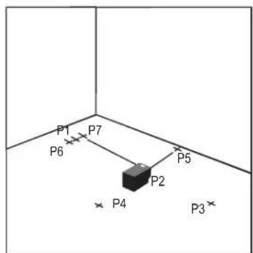
- Mark point P1 on the floor at one end of the room, as shown in Figure J#1.
- Turn the laser ON and press @times to display dots above, ahead, below, and to the right and left of the laser.
-
Place the laser so that the down dot is centered over point P1 and make sure the front dot points toward the far end of the room (Figure Ⓙ #1).
-
Using a target to transfer the front level dot location on the wall to the floor, mark point P2 on the floor and then point P3 on the floor (Figure Ⓙ #1).
- Move the laser to point P2 and align the front level dot to point P3 again (Figure Ⓙ #2).
- Using a target to transfer the front level dot location on the wall to the floor, mark the location of two square beams as points P4 and P5 on the floor (Figure Ⓙ #2).
- Turn the laser 90° so the front level dot aligns to point P4 (Figure Ⓙ #3).
- Mark the location of the first square beam as point P6 on the floor as close as possible to point P1 (Figure J #3).
- Measure the distance between points P1 and P6 (Figure Ⓙ #3).
- If your measurement is greater than the Allowable Distance Between P1 & P6 for the corresponding Distance (D1) in the following table, the laser must be serviced at an authorized service center.
| Distance (D1) | Allowable Distance Between P1 & P6 |
| 7.5 m (25') 2.2 mm (3/32") | |
| 9 m (30') 2.7 mm (7/64") | |
| 15 m (50') 4.5 mm (3/16") | |
- Turn the laser 180^ so the front level dot aligns to point P5 (Figure J #4).
- Mark the location of the second square beam as point P7 on the floor as close as possible to point P1 (Figure Ⓙ #4).
- Measure the distance between points P1 and P7 (Figure ⭕ #4).
- If your measurement is greater than the Allowable Distance Between P1 & P7 for the corresponding Distance (D1) in the following table, the laser must be serviced at an authorized service center.
| Distance (D1) | Allowable Distance Between P1 & P7 |
| 7.5 m (25') 2.2 mm (3/32") | |
| 9 m (30') 2.7 mm (7/64") | |
| 15 m (50') 4.5 mm (3/16") | |
Using the Laser
GB
Operating Tips
• Always mark the center of the beam created by the laser.
- Extreme temperature changes may cause movement of internal parts that can affect accuracy. Check your accuracy often while working.
- If the laser is ever dropped, check to make sure it is still calibrated.
- As long as the laser is properly calibrated, the laser is self-leveling. Each laser is calibrated at the factory to find level as long as it is positioned on a flat surface within average ± 4^ of level. No manual adjustments are required.
- Use the laser on a smooth, flat, level, surface.
Turning the Laser Off
Slide the Power/Transport Lock switch to the OFF/Locked position (Figure A #1a) when the laser is not in use. If the switch is not placed in the Locked position, the laser will not turn off.
Using the Laser with Accessories

WARNING:
Since accessories other than those offered by Stanley have not been tested with this laser, use of such accessories with this laser could be hazardous.
Only use Stanley accessories that are recommended for use with this model. Accessories that may be suitable for one laser may create a risk of injury when used with another laser.
The bottom of the laser is equipped with 1/4-20 and 5/8-11 female threads (Figure B) to accommodate current or future Stanley accessories. Only use Stanley accessories specified for use with this laser. Follow the directions included with the accessory.
Recommended accessories for use with this laser are available at extra cost from your local dealer or authorized service center. If you need assistance locating any accessory, please contact your nearest Stanley service center or visit our website:
http://www.2helpU.com.
GB
Using the Laser with the Multibracket
Most line/dot lasers which have a 5/8-11 mounting thread can be used with the Multibracket FMHT77435 (Figure K). The multibracket can then be used free-standing or mounted in several ways:
- Use its rubber strap around a pole, 2"×4", or other vertical object.
- Use its rear magnets against a metal beam.
- Hook its rear screw hole over a nail or screw on a wall.
- Use its ceiling clamp to hold onto the track for a hanging/suspended ceiling.
- Use the bottom 5/8-11 or 1/4-20 thread to attach to a tripod.
Maintenance
- When the laser is not in use, clean the exterior parts with a damp cloth, wipe the laser with a soft dry cloth to make sure it is dry, and then store the laser in the kit box provided.
- Although the laser exterior is solvent resistant, NEVER use solvents to clean the laser.
- Do not store the laser at temperatures below -20 °C (-5 °F) or above 60 °C (140 °F).
- To maintain the accuracy of your work, check the laser often to make sure it is properly calibrated.
- Calibration checks and other maintenance repairs may be performed by Stanley service centers.
Troubleshooting
The Laser Does Not Turn On
• If AA batteries are being used, make sure:
- Each battery is installed correctly, according to (+) and (−) listed inside the battery compartment.
- The battery contacts are clean and free of rust or corrosion.
- The batteries are new, high-quality, name brand batteries to reduce the chance of battery leakage.
- Make sure the AA batteries are in proper working condition. If in doubt, try installing new batteries.
- When using rechargeable batteries, make sure the batteries are fully charged.
- Be sure to keep the laser dry.
- If the laser unit is heated above 50 °C (120 °F), the unit will not turn ON. If the laser has been stored in extremely hot temperatures, allow it to cool. The laser level will not be damaged by using the Power/Transport Lock switch before cooling to its proper operating temperature.
The Laser Beams Flash
The lasers are designed to self-level up to an average of 4^ in all directions. If the laser is tilted so much that the internal mechanism cannot level itself, the laser beams will flash indicating that the tilt range has been exceeded. THE FLASHING BEAMS CREATED BY THE LASER ARE NOT LEVEL OR PLUMB AND SHOULD NOT BE USED FOR DETERMINING OR MARKING LEVEL OR PLUMB. Try repositioning the laser on a more level surface.
The Laser Beams Will Not Stop Moving
The laser is a precision instrument. Therefore, if it is not positioned on a stable (and motionless) surface, the laser will continue to try to find level. If the beam will not stop moving, try placing the laser on a more stable surface. Also, try to make sure that the surface is relatively flat and level, so that the laser is stable.
Service and Repairs
Note: Disassembling the laser level will void all warranties on the product.
To assure product SAFETY and RELIABILITY, repairs, maintenance and adjustment should be performed by authorized service centers. Service or maintenance performed by unqualified personnel may result in a risk of injury. To locate your nearest Stanley service center, go to http://www.2helpU.com.
Specifications
GB
| FMHT1-77415 FMHT1-77442 | ||
| Light Source Laser diodes | ||
| Laser Wavelength 630 – 680 nm visible 510 – 530 nm visible | ||
| Laser Power ≤1.0 mW CLASS 2 LASER PRODUCT | ||
| Working Range 20 m (65') | 50 m (165') with Detector | 30 m (100')50 m (165') with Detector |
| Accuracy - all lines and dots, except down dot ±3 mm per 10 m (±1/8" per 30') | ||
| Accuracy - down dot ±6 mm per 10 m (±1/4" per 30') | ||
| Power Source 4 AA Alkaline (1.5V) size | batteries (6V DC) | 4 AA Alkaline (1.5V) size batteries (6V DC) or 4 AA NiMH (1.2V) size batteries (4.8V DC) |
| Operating Temperature -10 °C to 50 °C (14 °F to 122 °F) | ||
| Storage Temperature -20 °C to 60 °C (-5 °F to 140 °F) | ||
| Environmental Water & Dust Resistant to IP54 | ||
Inhalt
D
| Distanza tra le pareti | Distanza ammissibile tra P1 e P3 |
| 6,0 m (20') 3,6 mm | (9/64') |
| 9,0 m (30') 5,4 mm | (7/32') |
| 15,0 m (50') 9 mm | (11/32') |
| 23,0 m (75') 13,8 mm | (9/16') |
Colocar as baterias AA
| Distânciaentre as paredes | Distância permissívelentre P1 e P3 |
| 6,0 m 3,6 mm | |
| 9,0 m 5,4 mm | |
| 15,0 m 9 mm | |
| 23,0 m 13,8 mm |
TYTO POKYNY USCHOVEJTE

TIETO POKYNY USCHOVAJTE

© 2017 Stanley Tools
N498963 - Rev C June 2017
http://www.2helpU.com




- GB
- Contents
- Laser Information
- User Safety
- Safety Guidelines
- WARNING:
- SAVE THESE INSTRUCTIONS
- Warning Labels
- Personal Safety
- Tool Use and Care
- Battery Safety
- Installing AA Batteries
- Using the Mounting Block
- Turning the Laser On
- Checking Laser Accuracy
- Horizontal Line Accuracy - Tilt
- Horizontal Line Accuracy - Level
- Vertical Line Accuracy - Plumb
- Plumb Dot Accuracy
- Level Dot Accuracy - Level
- Level Dot Accuracy - Square
- Using the Laser
- Operating Tips
- Turning the Laser Off
- Using the Laser with Accessories
- Using the Laser with the Multibracket
- Maintenance
- Troubleshooting
- The Laser Does Not Turn On
- The Laser Beams Flash
- The Laser Beams Will Not Stop Moving
- Service and Repairs
- Inhalt
- D
- Colocar as baterias AA
- TYTO POKYNY USCHOVEJTE
- TIETO POKYNY USCHOVAJTE
Brand : STANLEY
Model : FatMax FMHT1-77442
Category : Hand tool