
PRM1021 - Milling machine Ferm - Free user manual and instructions
Find the device manual for free PRM1021 Ferm in PDF.
| Product type | Router (plunge router) |
| Brand | Ferm |
| Model | PRM1021 |
| Supply voltage | 230-240 V~ |
| Frequency | 50 Hz |
| Power consumption | 1200 W |
| No-load speed | 9 000 - 30 000 min⁻¹ |
| Cutting depth | 50 mm |
| Collet (clamping chuck) | 6 mm and 8 mm |
| Weight | 3.5 kg |
| Sound pressure level (Lpa) | 86.5 dB(A) + 3 dB |
| Sound power level (Lwa) | 97.5 dB(A) + 3 dB |
| Vibration (total value) | 4.02 m/s² + 1.5 m/s² |
| Electronic speed control | Yes, by wheel (6 positions) |
| Parallel guide | Included |
| Cutting guide (template) | Included |
| Dust extraction adapter | Included |
| Rotary depth stop | Yes, 6 positions |
| Double insulation | Yes, no grounding required |
| Package contents | Router, parallel guide, set of brushes, cutting guide, central spindle, dust adapter, key, 2 collets (6 and 8 mm), 3 router bits, manuals, warranty card |
Frequently Asked Questions - PRM1021 Ferm
User questions about PRM1021 Ferm
0 question about this device. Answer the ones you know or ask your own.
Ask a new question about this device
Download the instructions for your Milling machine in PDF format for free! Find your manual PRM1021 - Ferm and take your electronic device back in hand. On this page are published all the documents necessary for the use of your device. PRM1021 by Ferm.
USER MANUAL PRM1021 Ferm
Thank you for buying this Ferm product.
By doing so you now have an excellent product, delivered by one of Europe's leading suppliers.
All products delivered to you by Ferm are manufactured according to the highest standards of performance and safety. As part of our philosophy we also provide an excellent customer service, backed by our comprehensive Warranty. We hope you will enjoy using this product for many years to come.

For your own safety and for the safety of others, please read these instructions carefully before using this appliance. It will help you understand your product more easily and avoid unnecessary risks. Keep this instruction manual in a safe place for future use.
Introduction
The router has been designed for routing of wood and wood products. Check the machine, for loose parts and accessories from transport damage.
Contents
- Machine specifications
- Safety instructions
- Assembly
- Operation
- Maintenance
1. MACHINE SPECIFICATIONS
Technical specifications
Voltage 230-240 V~
Frequency 50 Hz
Power input 1200 W
No load speed 9.000 - 30.000/min
Cutting depth 50mm
Collet 6 & 8 mm
Weight 3.5kg
Lpa (sound pressure) 86.5dB + 3 dB(A)
Lwa (sound power) 97.5dB + 3 dB(A)
Vibration 4.02 + 1.5m / s
Vibration level
The vibration emission level stated in this instruction manual has been measured in accordance with a standardised test given in
EN 60745; it may be used to compare one tool with another and as a preliminary assessment of exposure to vibration when using the tool for the applications mentioned
- using the tool for different applications, or with different or poorly maintained accessories, may significantly increase the exposure level
- the times when the tool is switched off or when it is running but not actually doing the job, may significantly reduce the exposure level
Protect yourself against the effects of vibration by maintaining the tool and its accessories, keeping your hands warm, and organizing your work patterns
Contents of packing
1Router
1 Parallel guide
1 Carbon brush set
1 Template guide
1 Centre pin
1 Adapter for dust extraction
1 Spanner
1 Collet 8 mm (assembled on the machine)
1 Collet 6 mm
3 Router bits
1 Safety instructions
1 Operating instructions
1 Warranty card
Product information
Fig. A+B+C
- On/off switch
- Handle
- Base plate
- Fixing screws for parallel fence
- Spanner
- Collet nut
- Spindle lock
- Wing bolt for depth stop
- Depth stop
- Clamping lever
- Plunge depth scale
- Adjusting wheel for electronic speed control
- Dust extraction facility
- Parallel fence
15.Guiderod -
Depth stop revolver
17.Screws -
Templateguide
19.Dusttube
20.Centrepin
2. SAFETY INSTRUCTIONS
The following symbols are used in these instructions for use:

Danger of life and risk of injury as well as risk of damage to the machine in case of non-adherence to the safety instructions in these instructions of use.

Danger of electric shock.

Remove the plug from the mains socket.

Variable speed control.

Wear ear and eye protection.

Wear a dust mask.

Wear protection gloves.
Additional safety instructions
- Please check workpieces for any obstructions on the surface of the material, such as protruding nails etc., to protect the router head.
- Wait until the router has come to a complete stop before removing any blocked or routed material around the cutter. Use a long stick for this and never your finger.
- Please keep your hands away from the routing surface.
- Immediately switch off the tool if it starts producing any unusual noise or starts vibrating excessively.
- Please check that all parts are secure, tools are removed etc. before operation.

Always check that the power supply corresponds to the voltage on the rating plate.

Your machine is double insulated, therefore no earthwire is required.
- Immediately throw away old cables or plugs when they have been replaced by new ones. It is dangerous to insert the plug of a loose cable in the wall outlet.
- Only use an approved extension cable suitable for the power input of the machine. The minimum conductor size is 1.5mm2 . When using a cable reel always unwind the reel completely.

Prior to mounting an accessory always unplug the tool.

Wait until the machine has come to a complete standstill and the cutter has cooled down before replacing a cutter.
3. ASSEMBLY
Router Bit Selection
Depending on processing and application, router bits are available in the most different designs and qualities:
Router bits made of high speed steel (HSS) are suitable for working with soft materials, e. g. soft wood and plastic.
Carbide tipped router bits (HM) are particularly suitable for hard and abrasive materials, e.g. hard wood and aluminium.
Mounting and removing cutters
Fig. E
Only use cutters with a shaft diameter which corresponds with the size of the collet. Only use cutters which are suited for the maximum speed of the machine. The cutter diameter should not exceed the maximum diameter (see 'Technical specifications').
Never tighten the collet nut, if there is no router bit in the collet; the collet may be damaged.
- Press the spindle lock (7) and turn the collet nut (6) until it engages in the lock. Keep the spindle lock pressed during this procedure.
- Open the collet nut using the spanner.
- Place the cutter shaft in the collet (5).
- Tighten the collet nut so that the cutter is locked properly.
- Open the collet nut when you want to replace a cutter.
Adjusting the parallel fence ruler
The parallel fence is a useful tool for precision routing at a fixed distance from the edge of the workpiece.
- Place the desired cutter in the tool.
- Slide the parallel guide with the guide rods into the baseplate and tighten at the required measure with the wing bolts
Mounting the template guide
Fig. C
The template guide is a handy aid for cutting a pattern.
- Mount the template guide (18) on the router base (3) using the screws (17).
Mounting the adapter for dust extraction
Fig. B+D
Use the dust adapter for the extraction of dust. In case the adapter is not mounted on the machine, follow these instructions.
- Mount the dust adapter (13) with the screws (17) on the cutter sole (3).
- Place the tube of your vacuum cleaner on the dust tube (19).

Keep the outlet of the machine behind the machine for a good view on the workpiece.
4. OPERATION
The ON/OFF switch
-
To switch on the tool, press and hold the on/off switch (1).
If you release the on/off switch (1), the tool will be switched off. -
Do not put the machine down when the motor is still running. Do not place the machine on a dusty surface. Dust particles may enter the mechanism.
Usage tips
After switching the machine on, make sure the machine reaches full speed before using it on the workpiece.
- Clamp the workpiece and make sure that the workpiece cannot slide from under the machine during the cutting activities.
- Hold the machine firmly and move it evenly over the workpiece. Do not force the machine.
- Only use cutters which do not show any signs of wear. Worn cutters have a negative effect on the efficiency of the machine.
Always switch off the machine first before removing the plug from the wall socket.
Speed Preselection
The required speed can be preselected with the thumbwheel. Also during running the rotational speed can be adjusted.
1-2=low speed
3 - 4 = medium speed
5 = high speed
Max = maximum speed
The required speeds depend on the material and can be determined by practical testing. Furthermore router bits with a large diameter need a lower rotational speed.
Material Diameter Router bit Speed stages
Hardwood >20 mm 1-2
$$ 1 0 - 2 0 \mathrm {m m} 3 - 4 $$
$$ < 1 0 \mathrm {m m} 5 - \max $$
Softwood >20 mm 1-3
$$ 1 0 - 2 0 \mathrm {m m} 3 - 5 $$
$$ < 1 0 \mathrm {m m} 5 - \max $$
Aluminium >15 mm 1
$$ < 1 5 \mathrm {m m} 1 - 2 $$
Plastic >15 mm 1-2
$$ < 1 5 \mathrm {m m} 2 - 3 $$
After longer periods of working at low speed, allow the machine to cool down by running it for a few minutes at high speed with no load
Height setting of the router column
Fig. B
The clamping lever (10) is used to set the maximum height of the router.
The plunge depth is then fixed. This is usually necessary when using the tool on a special router table. Make sure the router column is not locked. The router can be pushed down against the spring force. Lock the router column using the clamping lever. The router is now locked and will no longer return to its original position.
Adjusting the routing depth
- Place the machine on the workpiece.
- Undo the wing screw (8) and fixing handle (10).
- Slowly move the machine downwards until the cutter makes contact with the workpiece.
- Tighten the fixing handle (10).
- Set the depth stop (9) to the required routing depth using the scale and secure it with the wing screw (8).
- Test the setting by completing a test cut on a waste piece.
Adjustment using the revolver-depth stop
The revolver-depth stop enables you to quickly choose between six different cutting depths. These are also determined by the adjustment of the depth stop (9).
For larger routing depths, it is recommended to carry out several repetitive cuts with lower removal rates.
- Adjust the required cutting depth by pressing the revolver-depth stop downwards and rotating the revolver-depth stop (16).
Using the centre pin
Fig. G
- To use the centre pin, insert one guide rod (15) with the centre pin (20) attached into the holes, either side of the base plate of the router.
- Secure the guide fence rod to the router at the required length by rotating the fixing screw (4) clockwise.
5. MAINTENANCE

Make sure that the machine is not live when carrying out maintenance work on the motor.
These machines have been designed to operate over a long period of time with a minimum of maintenance. Continuous satisfactory operation depends upon proper machine care and regular cleaning.
Cleaning
Regularly clean the machine housing with a soft cloth, preferably after each use. Keep the ventilation slots free from dust and dirt. If the dirt does not come off use a soft cloth moistened with soapy water. Never use solvents such as petrol, alcohol, ammonia water, etc. These solvents may damage the plastic parts.
Troubleshooting
Please find some potential causes and solutions to possible failure.
1 The operating switch is switched on, but the motor is not working
The electric circuit is broken
- Have the electric circuit repaired
- Wires in the mains plug or in the socket are loose
- Have socket and plug checked or repaired
- The switch is faulty
- Have the switch repaired
- Carbon brushes are worn
- Replace the carbon brushes
2 Routerrunsslowly
Variable speed set low
- Increase variable speed
- Motor is overloaded
- Reduce pushing force on router
3 Excessive vibration
- Bent cutter shank
-Replacecutter
Faults
Should a fault occur, e.g. after wear of a part, please contact the adress on the warranty card. Included you find an exploded view showing the parts that can be ordered.
ENVIRONMENT
In order to prevent the machine from damage during transport, it is delivered in a sturdy packaging. Most of the packaging materials can be recycled. Take these materials to the appropriate recycling locations.

Faulty and/or discarded electrical or electronic apparatus have to be collected at the appropriate recycling locations.
WARRANTY
The guarantee conditions can be found on the separately enclosed guarantee card.
The product and the user manual are subject to change. Specifications can be changed without further notice.
OBERFRASE
3 Vibrations excessives
- Manche de lame courbé
- Remplacez la lame
Pannes
Putere consumata 1200 W
Turatie fara sarcina 9.000-30.000/min
Adancimea de taiere 50mm
Mandrina 6 & 8 mm
Greutatea 3.5kg
Lpa (presiune acustica) 86.5dB + 3dB(A)
Lwa (putere acustica) 97.5dB + 3 dB(A)
Vibrati 4.02 +1.5 m/s 2
Apsorbovana snaga 1200 W
Brzina bez opterecenja 9.000 - 30.000/min
Dubina glodanja 50 mm
Prstenasti osigurac 6 & 8 mm
Težina 3.5 kg
Lpa (zvučni pritsak) 86.5dB + 3 dB(A)
Lwa (zvučna snaga) 97.5dB + 3 dB(A)
Vibracija 4.02 + 1.5m / s
Nivo vibracija
Nivo emisije vibracija naznačen na poledini ovog uputstva za upotrebu izmeren je u skladu sa standardizovanim testom datim u EN 60745; on se moze koristiti za uporedenje jeder atakte sa drugom, kao i za preliminarnu procenu izloženosti vibracijama pri korišćenju ove atakte za pomenute namene.
1. TEXHINUCKNE XAPAKTEPNUCTUKN
TexHueeckne xapaKTepeNCTUKN
HanpajkeHne 230-240B\~
Yactota 50
Iotpe6nemmaMOuHocTb 1200BT
CkopoocTb 6e3 Harpy3KN 9.000-30.000/MnH
Iy6HnApe3Kn 50 MM
LaHROBbI NaTPOH 6&8MM
Bec 3.5 K
Lpa (3BykoBoe daBneHne) 86.5dB+3dA(A)
Lwa (3BvKOBaMAOuHOCtB) 97.5dB+3D5(A)
Bn6paun 4.02 +1.5 m/c2
YpOBeHb Bn6paUIM
YpOBeHb Bn6paun, yKa3aHHbB KOKUe daHHorO pyKOBODCTBa nO 3KcNpyataun 6bl n3MpeH B COOTBeTCTBUN CO CTaHdApTN3nPOBaHHbIM NCblTaHneM, codepXkaumcraB EN 60745; DaHHa XapaKTepnCTnka MoKe TnCNoJIb3OBAtbcra DnA cpABHeHnO ODHO rHCTpyMeHTa C dpyrIM, a TaKxJe IJa IpeDbapntelbHO OueHKI BO3JeCTBnRA Bn6paun Ipr NcNOJIb3OBAHm DAHHORo IHCTpyMeHTa IyKa3aHHbIX cJeIeN.
-ПриИСПОЛБЗOBAHМ ИСТРУМЕТА В ДPyгИХ
-целЯх Илис ДPyгИМИ/HeNCSPаВнIM
-ВСПОМORAteЛьНБIMпИСПОСОБLEнЯМИ
-уровенВОЗДeйСТВИВИБрацINMOжET
-ЗЧИТELьНОПБИШАТСЯ.
B nepnoDbI, KOrda uHCTpyMeHT OTKJIIOUeH nnФyHKuOHnpyet 6e3 qakTnueCKoRbBbINOJIHeHn paObToI, yPOBeHb BO3dEInCTBnBn6paun MoKeT 3HaunTeNbHO CHNkaTbcra.
3aunuTe Ce6o OT Bo3eICTBnBnbaHn, NopdepxNBA HNCTpyMeHT Iero BCnOMOraTeNbHbIe npucnoCoJIeHnB INcnpaBHOM COCTOHN, NopdepxNBa pyKn B TeNHe, a TaKKe npabUNbHO OrpaHn3OByra CBOI paobOn npocecc.
KOMNJIeKTHoCTb
1ΦaCOHHo-Φpe3epHbI CTaHOK
1 PapaJIeJIbHaH HAnpaBnaIOuaa
1 KomnneKt yroIbHbIX ueTOK
1 HanpaBnaOuaIywa6NoHa
1 Landa
1AanTepnnyaJaleHnnybIn
1TaeHbI KJIHO
1 LauHroBbI NaTPOH 8 MM (ycTaHOBHeH Ha o6OpyDoBaHN)
1 LaahroBbI naTpoH 6 MM
3 HacaKn faoHHo-Φpe3epHoro cTaHaKa
1 INCTpyKUna no 6e3oNaCHOCTN
1 PykoBOCTBO NO 3KcNlyaTaun
1「apaANTHnHbIΦopMnyarp
Hhopmaqna 6 n3deJnn
Pnc. A + B + C
- BbIKHIOUaTeIb NITaHn
- PykoTka
- OnopHaa nlaCTnHa
- KpenekHbIe BnHTbI dI naPanneBHOH napBaJIIOUeI
- Raeyhbi KJIIOH
- Raika zaHn
- YctpoCTBO 6loKnpOBKn WInHdJIa
8.Баразшковынбглгограичтелгубнbl - OrpahnHHTeB rIy6HbI
10.3aXmHna pyKoRTka - Shkana rny6nHbI norpyxhenia ppe3bl
- Koléco peryuipOBKn dπa 3JIeKtpoHOrO ynpabLeHnckOpocTbO
13.ПыileynoBITeIb - Napapallehna HnpaBnaOa
- HanpaBraIooi nCTepXKeHb
16.Баразаногранчтелглубнbl - BnHTbI
- HanpaBlaIOUaJaIwa6LoHa
19.Пьilec6bOpHnK - Landa
2. YKA3AHNЯ NO TEXHnKE 6E3OJACHOCTN
B daHHoH nHCTpyKcunn HcNoJIb3yIOTcneDyUOuNe 3HaKn:

Onachoctb JIJI KIN3HNI, PnCK NOLyueHn TpaBMbl, a TaKKe pNCK NOBpeXJDeHn ObopyoBaHnB B CInyae HecO6JIIODeHn npaBN TLexHnKn 6e3OnaChocTn, nPnBeDeHHbIX B DaHHOM pyKOBoDCTBe No 3KcNJIyaTaUH.

Onachoctb npaxKeHn 3neKtpnueckm TOKOM.

BbHMaIte WTeNcEJIbHyIO BuJIKy n3 pO3eTKI.

Плавhoeperуларовсckopoctn.

Ponb3yntecb 3aunTHbIMn OOKAMN CpeCTBaMn 3aunTbI Cnyxa.

BoBpempaobToIHaJeBaItepecnnpaTop.

HaedeBaIte 3aunTHbIe nepuaTkn.
DOnOpHnTeIbHbIe npaBnla TexHnKn 6e30NaCHOCTn
- Поберьтаб罗TOВКи Ha Haniuye KaKuxIIn60 Инордых TeI Ha NOBepxHocTmMaTePnala -HaNPIMeR, BbICtynaIOUnxrBO3deN T.D.
- Ipeed Tem, Kaq ydaJIntb KaKne-JI6O OTXoDbI MaTePnJa c NOBepxHocTn BOKpyr CTAHka, DOxDNITecb eRo NOJHON OCTaHOBKn. JIy 3TOFO NOJIb3yIteCb DInHHoN NaIOUKOH IN HIKORDa He NbTaIteCb DeNaTb 3TO NaJIbCuAMN.
ДерхиTe pyknHa paCCToHnOTo6pa6aTbIbAemOn NOBepXHOCTN.
HemeIeHHo BbIKIOUHTe INHCTpyMeHTB Cnyae NOBLeHnKaKOrO-JIn6o HeO6bIuHoro 乌Ma nn Upe3MepHoB Bu6paun. - Pered Naqalom pa6oTbI y6eHntecb B TOM, YTO BCE DeTaJn HndexKHO 3aKpeNHeHbI, a INHCTpyMeHTbI ydaJeHbI C 3aROTOBKn.

Heo6xOIOMO 683aTeIbHO y6eIITbcB TOM,HTO HApJKeHne NCTOCHNka IHTaHncoOTBeTCTByET YKa3aHHOMy Ha WIIJIbDNIke.

JaHHoe obOpyIOBaHne IMeET BoHyIO n3OJIaIIO, PO3TOMy 3a3eMJIeHne He Tpe6yeTc.
Heo6xoJIMHOmeJeHNOyTIN3npoBaTb cTapbI npOBODnnuTEnCeJIbHyIO BnIKy BcLyueix 3aMeHbI. POnKlUoyHe nTEncBHOBnIKNOTpe3aHHOrO npOBoKa CTeBOPO3eTKe-0NaCHO.
IcnoJb3yIte ToJIbKO peKOMeHIOBaHHbIe ydINHInTeJI, COOTBeTCTByIOUe 3HaueEHIO BXoJHO MOUHOCTn INHCTpyMeHTa. MnHMaJIbHbI pa3Mep npOBOnHka -1,5 MM2. PpNcNoJb3OBAHN Ka6eJIbHoro 6apabaha Bcerda pONHOCTbIO pa3MaTbIBaIte npOBoJ.

Ipeepc6opKoBcerdaOTKIOUaHTe HnCTpyMeHrOTcTuNTaHn.

Ipe3aMeHOn pexyueH hacakn,doXntecb noHoi OCTaHOKn cTaHka nOxJxdeHna fpe3bl.
3. CBOPKA
Bb6op hacaok facoHno-phiepHoro cTaHka
B 3aBnCmOCTn OT Tnna o6pa6oTK n o6laCTn npImeHHeN, nCNoJIb3yIOTcpeKyuIe HacaKn pa3JIuHbIX TINOB N KaueCTBa: PekyuIe HacaKn n3 6bICTpopeKyuIe INCTpyMeHTaIbHO n CTaII (HSS) noXoJrT dJa pa60tbc MArKIMM MaTePnAJaAMn, HApPImep, MrgkON DpeBeCInHO n IPLactMaCCo. HacaKn c TBepDOcIIaBbIMn peKyuIMN nnactNaHAmn (HM) Ooc6eHNO noXoJrT dJa TBepDbix a6pa3INBbIX MaTePnAJoB, HApPImep, TBepDoDpeBeCInHbI n aIOMHHN.
YcTaHOBka N ydaJIeHne peKyuInx HacaIOK Pnc. E
IcnoJb3yUte TOnbKOpeKyuUneHaKOHeuHKn, dNaMeTpweKNKOTOpBX COOTBeTCTByeT dNaMeTpuy cAHROBOrO nATPOHa. IcNoJIb3yUte TOlbKOpeKyuUneHaKOHeuHKn, COOTBeTCTBYUOUIe MaKcIMaJIbHOINCKOPoCTn CTaHka.DNaMeTppeKyuUeIO HcHTpymeHTa He DOJIKeH pReBbUaTB MaKcIMaJIbHbI INaMaTeP (cm.TexHnueckNe xapaKTepnCTnKn'). HIKoRda He 3aTgINBaIe raiKy cAHROBOr OnatpoHa npN OTCyTCTBUN yCTaHOBLeHHo HacaDN; 3TO MOKeT pInBecTN K NOBpeXdEHNO UaHROBOrO nATPOHa.
Haxmte KhoNky 6loKupOBKn UHHnHdJIa (7) nIOBopauBaIte raiky cAnroBO rNaTPOHa (6)doTexnop, noka OHa He BoiJeT B KOHTaKT C yCTpoIcTBOM 6loKupOBKn. YdepXuBaIte KhoNky 6loKupOBKn HaxaToB TeueHne Bcei 3ToI npOeDpybl.
C nomou bjo raeHoro kIIOa ocna6bTe raKy 1aHROBOr noTPOHa.
- NomeCTnTE Φpe3epHyIO onpaBky B ZaHroBbI naTpoN (5).
3aTaNHTe raiKy 1aHROBOro NaTPOHa TaKIM o6pa3OM, YTO6blΦpe3a 6bIina DOJXHBiM o6pa3OM 3aΦNKCuPOBaHa.
- Pn Heo6xoJIMOCtN 3aMeHbI fpe3bl, ocna6bTe raKy caHROBOrO naTPOHa.
PerynpoBka Hapablaioe JInHeKu
HanpaBlaIOUaJINHeNka npedCTabIaTe cObO OyeHb yOoHbI INHCTpyMeHT dIa TOuHOI paCOHHo pe3Kn I ppe3epOBAHnHa 1KcnpOBAHOM pacCToHm OT yIa 3aTOBKn.
- YctaHOBNTe HxKHyIO qpe3y.
CdbnHbTe HnpaBnaHOyU JInHeKy, HnpaBnB HnpaBnaIOuNe CtepXHN K onOpHoIJaCTnHe, n 3aTaNHe Do HyxHOro MOMeHTa c NOMOsb6apaKOBbIX 60lTOB.
YcTaHOBKa HnpaBnaIooJe dIra 7a6JNoHa
Pnc.C
HanpaBraIouaJnla 7a6NoHa OueHb yO6Ha InBa Bbipe3Anna 7a6NoHOB.
- YctaHOBnte HnnpabIyU OJn Iua6NoHa (18) Ha oChOBaHne facOHNO-Φpe3epHoro cTaHka (3) c NOMOuBbU BnHTOB (17).
YcTaHOBka aAnTepa nbIeynIOBtEnr
Pnc. B+D
ПынеловпьИСNOЛБ3уETсДЯ OTcaSbIBAHЯ Пыл.ЕсиаДАNTep He yCTaHOВЛeн Ha Baшem CTaHKe, BbINOJIHNTe CleDyUOUIne DeIcTbNr:
- YctaHOBnTe nbIeYIOBnTeJIb (13) c nOMOuBIO BnHTOB (17) Ha noDOWBy fpe3bl (3).
-Помecntte Tpy6ky nbIeococa B nbIeocbOpHnK (19).

IopndepxuBaIteOTBepCTne3aHne
yactn HnCTpyMeHTa CBO6oHbIM, YTO6bl
OBeCneHTb XOpOwUo BNIMOCtB
IOBepXHOCTN 3aROTOBKn.
4.3KcπJyATAUЯ
BbIKJIOyateJIb NITAHN
- 4To6bI BKNIOHHTb INHCTpyMeHT, HAXMnTe N ydepXnBaIte BbIKIOHAteJIb (1).
- Ecnn Bbl OTnycTnte BbIKIOuataTeIb (1), INHCTpymEtBbIKIOUHTcR.
He KnaIte HnCTpymeHT,ecn DbIraTeIbe eue He octaHOBLeH.He cTaBbTe nHCTpymeHT Ha nbIbHyIO NOBepxHOCTb. YaCTNuIbI bIIMoYr InonAcTb BHyTpB MexAHn3Ma.
PekomeHdaun no nCnoB3ObaHnIO
- Pocne BkIIOUeHnI INCTpyMeHTa,doXdntecb, noka OH HabepeT nonHbIe 6obopoTb,IpeXJde Yem IcNoJIb3OBAtB eO IIN 3aTOBKn.
3aФИКСИРУТЕ 3aROTOBky C NOMOUII 3aXIMOB I y6eINTEcB B TOM, YTO OHa He MoXkET yNactb IOd INHCTpyMeHT B INPOUCECE pe3KN. - Пючно уdeckжиBaIte Инстумент и посяаиTe erO hab 3arotobKoN c paBHOMepHoi ckopocTbIO. He npilaraTe ype3MepHbIe ycIIINIA N He nbITaHTecb yckOpNTb pa60Tu cTaHka.
IcnoJb3yIe ToJIbKO fpe3bl, He ImeIoUne IOBpeXdEHN nn CNeOBo N3HOca. H3HOweHHBe fpe3bl OTPuCaTeJIbHO cKa3bIBaIOCTHa 3ΦΦeKTHBHOCTn pa60TbI INHCTpyMeHTa.
Bcerda chauana BbIKIOuaTe uHCTpyMeHT, npexKe HeM BbIHyTb wTeNCelbHyIO BuIKy I3 po3eTKI.
PpeBapnteIbHbI Bb6Op cKopoCTn
HyxHyIO CKOpocTb MoXHO Bbl6paTb C NOMOuBIO
DnCKOBOro nepeKJIouaTeIa. CkOpocTb
BpaueHnMoXHO peryInpoBaTb TaKke B
Ipouece pa60TbI.
1-2=Hn3KaacKoPoCTb
3-4=cpeHraCKopocTb
5 = BBICOKaCKOPOCTb
Max = maKcImMaJIbHaJ cKOpocTb
Bb6op ckopoCTn 3aBnCt OT MaTePnAHa N MoKet OnpedJIeTbcr MeToDOM npakTnueckoI npOBepKn. TaKIM o6pa30M, dIy fpe3 6OJIbWoOr OdnAmEtpa Tpe6ByETc 6OJIee Hn3KaR CKOpocTb BpaUeHnI.
Matern DnameTp hacaKcKopoctb
Tberpa >20mm1-2
DpeBecnHa
10-20mm3-4
<10 mm 5 - MAKC.
HactpoJa BBICOTbIO OCHOBAHnA facoHO-Φpe3epHOrO CTaHka
Pnc.B
3aXHMHO pyUar (10) nCNoIb3yeTcIy YCTAHOBKN MaKcIMMaJIbHO BbICOTbl φacOHHO-Φpe3epHOrO cTAnKa. 3aTeM φnKcIpyETcR rny6Ha norgPyKeHnФpe3bl. O6bIuHO 3TO Heo6xOJIMo npn IcNOJIb3OBaHN INHCTpyMeHTa Ha CneuaJIbHOM BepCTake. Y6eINTEcB TOM, yTO onopa faoCHHO-Φpe3epHOrO cTAnKa He 3aKpePHeHa. CtaHOK MOXHO ONyCTNTb BHN3, B HApRaBLeHnN, npOTNB cKATNA pPyXHHbl. 3aΦnKcIpyIte onopy faoCHHO-Φpe3epHOrO cTAnKa C NOMOUsIO 3aXHMHO pBluRa. TeNEpb cTahOK 3a6NkOpOBaH N He 6yDet BO3BpaAaTbcR B INCXODHoe NOLOXKeHne.
PerynnpOBKa rny6uHbI φpe3epoBaHn
- YcTaHOBInTe yCTpoIcTBO Ha 06pa6aTBiBaEMoe n3dJIne.
Ocna6ntb 6apaWKOBbI BnHT (8) npyKy 3aXmMa (10).
-ДигайуctpoICTBOMeIeHNO Bn3,doTexnopNokaФpe3a He npKocHTcKaO6pa6aTbIbAemomyИЗдELIO.
3aTMyTb pyuKy 3axnma (10). - YctaHOBInTe yNop rIy6nHbI (9) no uKaJIe Ha JeJaemyo rIy6nHy fpe3epoBaHHa N 3aФHKcnpOBAtB npi NOMOuN 6apaWKOBOro BnHTa (8).
- Побете КОнтpoь peгулрOBКИ np6HbIM Фpe3epoBaHem DeTALN n3 OTXOdB.
PerynipoBka c nomoob 6apa6bana- orpaHnUteIraLy6nHbI
Bapaban-OrpaHnHTeIb rly6nbl NO3BOJAreT 6bictpo Bb6paTb OndHO n3 WeCTb 3HaueHni rly6nbl pe3Kn. OHn TaXke OnpedeJIOTcpeYInpOBKO orpaHnHTeJI rly6nbl (9). Dn8 60nbIeO 3HaueHnra rly6nbl facOHHO pe3Kn peKOMeHdyETcB bINoHNTb HeCKOJIbKO nocJeIOBaTeIbHbIX pa3pe3OB C 6OJee HN3KNMI 3HaueHnAMN.
- OTPeryIpyuIte Heo6xOaMMyo rLy6nHy pa3pe3a,HaXIma Ha NobopoTHbI orpaHnHTeB rLy6nHbI, a TaKxE BpaUaJ noBopoTHbI orpaHnHTeB rLy6nHbI (16).
IcnoJb3OBAHne anphi
Pnc. G
ДяинспльбзованьцалфыВСТаБTeОДИН hapавлгюшийсторжень (15)сцалфои (20),3akpenlenhoBВOTBерстmax,CЛIOБОП CTOPOHblПNTbI OCHOBAHЯФpe3bl.
3akpeHnTe cTepeXeHb HnpaBJIIOUeJ IInHeKn Ha fpe3e, yCTaHaBJIIBaI Heo6xOdMMyDIIINHy, NOBopaHbA BnKcnpyUoNm BNHT (4) nO YacobOu CTpeJIke.
5. OBCJNYXKUBAHNE

Pn BInOJIHeHn TExHueeCKoRO 06CnyXnBaHn y6eIITecb B TOM, YTO INCTpyMeHT OTKIIIOueH OT CetN.
DaHbI INCTpyMeHT paCCuNTaH Ha dInTeBbIcPOK 3KcNlyaTaUIN Pn MNHmAlbHOMobCyXuBaHN. JnA dInTeBHO 6e30Ka3HOpa6oTbI Heo6xOAnMo OecneuTb npaBnBbIyXoD 3a INCTpyMeHTOM I erO peYJrphHyOCHCTKy.
OuNTka
PeyraHno, XeIaTeIbHo nocJe kaxdoRo
NCIOb3OBAHnI, IpOTnpaiTe DeTaN KOpnyCa
NHCTpyMeHTa MrgKo TkaHbIO. CneiTe
3a OTCyTCTBnEM nbINu 3aqr3HeHn B
BEHTNIAUHOHHbIX npope3Ax N peryAepHO
OuHaJte ux. EcIn rpa3b He ydaJIaETcR,
BOcNoJIb3yIteCb MrgKo TKaHbIO, CMOeHHoB
MbIbHOM pactBope. HnkOrDa He uCNOb3yIte
dAn OuchTK INCTpyMeHTa TaKHe pactBopNTeIN,
kak 6eH3nH, cnpT, hauaTbIPbHn CnIpT n
T.d. 3TN pactBopNTeIN MOYr NOBpeDnTb
PiactMacCOBblde Detann.
DnarHocTnka n ycTaPaeHne HncnPabHOcTei
Ha cIeMyoUe CtpaHnue npuBODrTc HekOTOpbIE BO3MOXHbI npuHbI n CnOc6bI yCTpaHeHnE HeNCnPpABHOCTe.
1 BbIKHouateIb HaxoIITcBO BKJIIOueHHOM
noLoXeHn, Ho DbVaTeJIb He pa6oTaET
- H3HOWeHbI yroJIbHbIe IeTKn
3aMeHnTb yroJIbHbIe IeTKN - Θлектуpeckий КОТун NOВпждЕн
IouHHnTb 3JIeKtpuYeckn KOHTyp
-Плoxон Конткп npOBOD WTeNCeIbHOn BUNKINpO3ETKN
IpoBepuTb u, npn Heo6xoJIMMOCTn, NOUHHTb UTeNCeJIbHyIO BuNKy u PO3eTKy - BbIKJIouaTeIb HeuCnpaBeH
NoHHHTb BbIKIOHataTeJIb
2ФacOHHO-Φpe3epHbI cTaHOK pa6oTaet MeJHeHHO
- YctaHOBNeHO Hn3Koe 3HaueHne CKOpOCTN
3aatab 60Jee BbICOKyIO CKOPOCTb - Perperpy3ka DBrarateJra
- Chn3ntb TOnKaIOuee ycNne Ha faoHNOfpe3epHbI CTAHOK
3 4pezmepnha Bn6paun
- Norgytaфpe3epna onpaBka
3aMeHnTbΦpe3y
HencnpabHoctn
Pn BO3HKnHOBeHn HeuCnpaBHOCTn, Hapmep, BCJeDCTBHe N3HOca DeTaJI, O6paTntecb B cepBnCHbI ueHTp No aDpeCy, yKa3aHHOMy B rapaHTnHOM fOpMylpe. B KOMnIeKT noCTabKN BXoNT npocTpaHCTBeHHoe N3O6paXKeHne DeTaJIe n C6OpKn N3dEJIra C yKa3aHHe M DeTaJIe, KOToPBle MOxHO 3aKa3aTb.
OKPYXIAOUIA CPEDA
Длгпрдовашия nobpeждени Инстумента ВОВЕМЯТраHCNOPTYPOBKN, OH NOCTABЛЯETСВ B ПОЧНУПAKOBKE. БолшинстBO MaTeРиАLOВ упakOBКИ NOДпEXКAT NOBTOPнОпЕрбОТК.ИХ Heo6xOДIMO пeретаьВ COOTBEТСТВуОШеNYHKTы NOBTOPнОпЕрбОТК.

HencnpaBHyI nn6oJe He npuOHyI
IyNCNoJb3OBaHnY IHCTpyMeHT
Heo6xOIMo CdaTb B COOTBeTCTByIOUne
NyHKtbl Iy nepepaOToKn.
TAPAHNTY
TapaHTNnHbIe ycIOBnCm. Ha npUlaRaEMOM rapaHTNHom TaHOHe.
N3dene n pyKOBOcTBO noIb3OBaTeIa MOryt 6bITb N3MeHeHbl. TexHnueckne XapaKTEpncTNI KMOrYT 6bITb N3MeHeHbl 6e3 DaIbHeIwero yBeDOMJIeHnI.
ФАСОНHO-ФPE3EPHи BEPCTAT
JaKyemOBam 3a KyniBIO npOdyKTy KOMnaii Ferm.
3diIChIOUcN KynIBnO, BN OTPmUeTe BiMInHn ToBap BiOndHO 3 BeDyux NoCTaHaJIbHnKIB y Cbponi.
Yci npoodykTn BiD KOMnaHii Ferm BuroTOBJIeHi y BiINOBiIDHOCTI Do HauBnUx CTaHapTiB npoodykTNBHOCTI Ta 6e3neKn. Mu HadaeMo NOKynIO NOcnyn HaBnUOJ kOcTI, 3acBiJeHi rapaHTieO Ha BnPiOy u cIOMy.
CnoiBaemocb, Bn 6yndeTe KopncTyBaTncra daHIM npodyKTOM npotrrom 6araTbox pokib.

Iblachoi6e3neKnTaIb6e3neKn IInxIIOe,6yJaIacKa,yBaXHO npouHTaTe ci IHCTpyKii neped BIKOpNCtAHNcMbOro npucTpoU.Le OONOMOKe Bam Kpaue 3pOzymTu cei npOdyKT Ta yHnKHyTN HeNoTpiohIX pn3NKIB.36epiraNe Tc KePibHNTBOB HadiHOMy Micci IJr NdaJIbWoRO BIKOpNCtAHN.
BVeEeHn
LeyfaoconHo-phiepHnBepCTa6ylo po3pObleNoIra faoconHoroΦpe3epyBaHHa DepeBnHa Ta depeB'raHx Bpuo6i. PepeBipTe MaunHy, BiD'edHaHi DeTani Ta obnAnHaHHa Na ppeMet noWKoJKeHHn iD yac TpaHCnpTyBaHHa.
3mict
- TexhiHy XapaKTePncTnK MauHH
- Ihctpykuii oio 6e3nekn
- 36opka
- BnKOpncTaHHa
- TexhiHHe 06cIyRObyBaHHa
1. TEXHIYHI XAPAKTEPNCTIKM MALUNHN
TexhiHcneuΦikaui
Hanpyra 230-240 B~
Yactota 50
BxiHa noTyXHicTb 1200BT
UbukicTb 6e3 HabaHTaXeHH 9.000-30.000/xB
Пибна розпань 50 MM
LaHROBNIaTPOH 6&8MM
Bara 3.5 Kr
Lpa(Tmck3Byky) 86.5dB+3dB(A)
LwA (noTyXhicTb 3Byky) 97.5dB + 3 Ω(B(A)
Biopaia 4.02 +1.5 M/c
Pibehbbiopauii
Pibehb Bi6paui, 3a3naeHn B KInci daHoro
noci6nka 3 ekcnnyataui, 6ylo BmipraHo
y BiIOBIOHOCTi 3i CTaNapTn3OBaHIM
Bnnpo6yBaHHam, 10MiCTNbC8 B EN 60745; daHa
xapaKTepcntika
MOXe BIKOPNCOTByBaTncr DnI NopIBHNHn
ODHOrO IHCTpyMeHTa 3 iHsIM, a TAKOX dJI
NONepdNbooi OcIHKn BnINBy Bi6paui nID
cac 3actocyBaHHra DaHORO IHCTpyMeHTa dJI
BkzaAHnx ciJei.
- npn BnKOpncTaHHi IHcTpymeHaB iHux cIjAx a6o 3 iHmMn/HeCnpaBHmN dONOMIXHMn npNCTOyBaHHaMn pBeHb BNBy Bi6paqii MOKe 3NaHNO nIDBnUyBaTnCra.
y nepioN, KOJI INCTpyMeHT BIMKHeHn a6o cyHKIOHyE 6e3 paKTNUHO BO BVKOHaHH po6OTn, pIBeHb BNINBy Bi6paui MoKe 3HaUHO 3HNKyBaTnCra.
3axnauTe ce6e BiD BnInBy Bi6pauii,
niTpmyuOn iHcTpymeHT iNoTo DonomixHi
npCTOCyBaHHB CnpaBHOMy cTaHi,
niTpmyuOn pyKn B TeNl, a TaKoK npaBnIbHo
OrpaHn3OBuOn Cbi pOboUH npocec.
Bmictynakobkn
1 PaocHO-Φpe3epHn BepCTaT
1 PapanelbHa HappaBlyiocha
1 Ha6ip ByrilbHnx zitok.
1 HanpaBjaOua wa6JOna
1 LiBopiHb
1AanTePnIINOBIOBIOBAHH
1 RaIKOBNI KJIHO
1 LcaHROBn natpoH 8 MM (BCTaHOBJeHn Ha MaunHy)
1 LaHroBn natpoH 6 MM
3 BcTabKn faoHHO-peepHoro BepCTaTy
1 Ihctpykuqii 3 texhikn 6e3nekn
1 Ihcpykci3 ekcnnyataaii
1「apaHTiHm TaOH
2. IHCTPyKciI ⅢOIO Bc3NEKN
Bux iHCTpykuiBX BUKOpNCTOBYIOTBc HAcTyNHi CmBOJn:

He6e3neKa dJa KHTTa np3nK TpaBMn, a TaKoK np3nK N0WKoJKeHHa MaunH y BnapKy HeIoTPMaHnH iHCTpyKciN 3 TexhIKn Be3neKn, BnKnaDeHNX BcBOMy KepiBnTBI.

He6e3neKa ypaKeHHa eNeKtpuHm CTpyMOM.

BntarHitb Bnky 3 po3eTKu Mepeksi KUJIeHHa.

P3Hn KOHTpOJIb UBNKoCTI.

OJaHITb 3ac06n 6e3neKn Ipn Ouey Ta Byx.

OjarrHtB npotnnuNOby Macky.

OdIgHITb 3axnChi pyKaBnCi.
DogaTKoBi iHCTpyKuIi 0do6e3neKn
Будлackа,певір'te Detani Ha HЯВHICTb
HepiBHOCTeNoBepxHi MaTepiAly,HaPnIKlaI,
BvuctyaIOUcTBaXn ToIo,Io6 3axNCTu
roJibKy faconHo-Фpe3epHOrO Bepctaty.
3auekaTe,doKn faoconHno-phi3epn H BepCTaT NOBHCIO 3ynnHITbcra nepeD Tm, Ra BuaJIaTI MaTePiaI, 0o 6IoKye fpe3y. IJIa CbOro BnKOpNCTOByTe DOBry NaIKy, HiKOn He po6iTb ce naIbCzAMN.
-Будлackа,ТримаTe pykn noДaI BiDФpe3yBaIbHoI nobepxHi.
- HeraiHo BUMKHiTb IHCTpyMeHT, JkUO BiH nouHaEc yTBOpIOBaTu He3BuayHn 3Byk a6o nouHaEc HAdMpHO Bi6pyBaTu.
- Byd nacka, nepeB BnKOpncTahHm iHcTpymEnTu nepeBipTe, 0o Bci deTani do6pe 3akpinHei, Bci npnilaJra 3Hrti Ttoio.

3aBXn nepeBipraIte, 0o6 eJektpnHe XNBLeHn BIDNObIaNo Happy3i, 3a3NaeHi Na Ta6NcI 3 nacnOpTHMn DaHIMN.

BaHa MaunHa Mae noDbiny i0JauHIO, TOMy 3a3eMJeHH He e Heo6xizHM.
- Heraин Викиные CTapi Ka6eni Ta
- Tencelhi BnKni nicra iXhboi 3amHn.
- He6e3neuHO BCTabIaTIu TencelHy BnKy
- BInbHorO Ka6eIIO B po3eTKy Ha CTINI.
BukopucobuyTe TlkbNnpebipeHi Ka6JIbHi noobkyaui IJn eIeKtpuHOrO KINBHeHHaMaunH. MiImaJIbHn p03Mip npoBiHNka
1.5 MM².Пд уас ВИКОРиСТаHHЯ Ka6eьHOrO 6apa6aHy 3aBxДи NOВHICTU po3MOTyIte 6apa6aH.

IpeyctaHOBOIO DOONOMIXHORO
0bnaHaHH3aBXn BmVKaHTe
iHCTpyMeHT 3po3eTKN.

Ipeep 3amHIO ppe3n 3auekaite,OKMaunHa NOBHICTO 3ynHHbCra Ta ppe3aNOBHICTO OXOJHOe.
3. 3BOPKA
Bn6ip BcTabOK facohho-epe3epHoro Bepctaty
lchyotb pi3HOMaHiTHi 3a DN3aHOM Ta BnactuBOCTaMI BCTaBKN IJI pyi3HNxCnOCo6IB 3aCTOCyBaHH:
BCTABKNfacoHNO-Φpe3epHoro Bepctaty 3i WbNdkopixyoi iHcTpymeHTaIbHOi cTani niDnytb dnypo6Otn 3 M'kIMMaTePiaIamn, HapniklaD, M'ka depeBHa a6o nlaactmaca.
BCTaBKn 3i TBepDocPnlaBHN M KInCem Oco6JnBO niiIyTb IJa TBePnX Ta a6pa3NbHnx MaTepiJIb, HApnKJa, TBepDa DepeBnHa Ta anHomiHi.
BcTaHOBHeHH Ta 3HimaHH Hpe3
Man. E
BukopncToByTe IuIe 0pe3n 3 TaKIM
diametpom XBOcTOBnka, 1o BiIDNOBidae po3mipy
caHROBOr NaTPOHy. BukopncToByTe IuIe
fpe3n, 1o IIxOJrTb IJIa MaKcImaJIbHOi
WBnIKoCTI MaunH. dIaMeTp fpe3n He NOBHeH
nepeBnUyBaTn MaKcImaJIbHOr O diametpy (INB.
"TexHiChi CneuΦikaui).
Hikon He 3aTnCKaIte raKy ZaHROBO rNaTPOHy, RaKIO BCTaBkA BepCTaTy He BCTaBNeHa B NaTPOH; IHaKWe ZaHROBn NaTPOH MOXHa N0WKODNTN.
HaTnCHiB 3aTnCK uHHdJIe7 (7) i NOBepTaIte raKy cAHROBO r NaTPOHy (6), DOKN BIn He yCTaHOBITbcR B 3aTnCK. TpImaJIte 3aTnCK uHHdJIe HaTnCHyTm NiJ Yac ciie I npOcEduPn.
BiiKpytibraKycaHROBOInatpoHy3a DONOMOROraIKOBOROKIIOUa.
BCTaTe xBOcTOBnK fpe3n B uHaHROBn natpon (5).
3akpiitb rainky zanroboro naTPOHy taK, 06 do6pe 3akpinTu pfpe3y.
BiiKpyTb raKy uahroBoro naTPOHy, KOIN Bu 6aKaTe 3amHHTn fpe3y.
HaataybaHHa iHnnapaJIbHnx 6mexyBaivB
IapaJIbHi 6mExyBaHi - KopUChn iHCTpyMeHT Ira ToHoro Bupi3aHHa Ha 3aФIKCOBAHI BiDcTaHi BiKpaIO 3arOTOBKn.
BCTaBTe Heo6xIDHy fpe3y B iHcTpymeHT.
- NepemictitbnapaJIbHi o6mexyBaHi 3a
DOnOMOROH HnpaBnaHoux UTaHr Do OnopHOI PInTu Ta 3aKpinitb Ha Heo6XiHn BiDCTaHI 3a DOnOMOROCTONOPHNX 60NTIB.
BctaHOBHeHHHaNPabIauOoi wa6NoHy Man.C
HanpaBIAIOUa 7a6IOna 3 KOpuCHOIO npn po6Oti 3 7a6JHOHOM.
BctaHObitb HnpaBnIOuy 7a6NoHy (18) Ha OCHOBy BepCTaty (3) 3a DOnOMOrIo rBnHTiB (17).
BctaHOBHeHH aanTepy dny nIOOBIOBAHH
MaJ. B+D
BnKOpNCToByTe aAnTep NIOOBNOBJIIOBAHNaI BnJaJIeHHaNly. JaAnTep He BCTaHOBJIeHn Ha MaunHy, BnKOHaTe HAcTynHi IHCTpyKciI:
BcTaHOBIb aadantep nIOOBNOBIAHn (13) 3a DOnOMOIOI GBnHTIB (17) Ha OCHOBy fpe3n (3).
- HaniHbTe Tpy6Ky CBOrO NnIOcoca Ha Tpy6Ky NnIOBNOBIIHOBAHHa (19).

YtpmyTe OTBip DnBndaIeHnny Maunn B 3aHiu cactnHi Maunn, uo6 do6pe bauHTn 3arOTOBky.
4. BUKOPNCTAHH
Nepemkau Bk./BmK
-Дя BBIMKHeHHI hCTpyMeHTy HATnCHiTb Ta yTpmyTe nepemkau BKn./BnKn. (1).
- YKUo Bu BiJNyCTnTe nepemukau BkN./Bukn. (1), IHcTpymeHT 6yJe BmKHeHO.
He KnaiItb MaunHy Ha nobepxHIO, KOIN DnBryn npaioe. He KnaiItb MaunHy Ha nIbHy nobepxHIO. YactnHKn Nny MoxyTb notpanNTu B Mexahi3M.
Iopadu odo BVkOpncTaHHa
-Пися BBIMKHeHHMaUNHn NepeKoHaITeCb, ь MaunHa DoCraI NaOBHOI WbNkOcTi nepei NiDHeceHHm Ioro Do IHCTpyMeHTy.
3akpiitb Bnpi6 Ta nepekoHaTeC8, 0o Bin He 3MOXe Bucn3HyTu 3 NiD MaunHn NiI qac po60Tu no piaHHIO.
MiUHO TpMaMATE MaunHy Ta nepeCyBaTe ii
piBHomipHo HaI Bnpo6oM. He npnknaaTe Do npunaTy 3aBnx 3ycnIb.
BukopncToByte Jnue 03HaK 3HOuYBaHH.BukOpncTaHH 3HOuEHH 0pe3 HeratubHO BnIbAc Ha eKeKTNBHicTb po6oTu npJnady.
3aBXKn BmKaNte MaunHy nepeD Tm, K BnHrTu BNkY 3 HactiHHOI PO3ETKn.
Bn6ip wbndkocti
Heo6xHa WbNdkicTb 0bnpaetbc3a
DonomoroIO DnCKOBOro nepemkaay. TaKox
MOxHa HanaTuBaTN WbNdkicTb nIac po6OtN.
1-2=Hn3bKaIWBnDkicTb
3-4=cepeHnWbNdkictb
5 = BINGOKa WBNKicTb
MaKc = MaKcImaJIbHa WBIuIκiCtB
Heo6xHa wBnKicTb 3aJexKntb BiD MaTepiany Ta Bn3HaayAc npakTuHm BnKOpNCtAHNM. Kpim TORO, BCTaBKn Bepctaty 3 6iNbWM diaMeTpOM BImaraOTb MeHooI wBnKocTi.
| Materiapan Дiametр Bctabka Фасонно- Фразерного Версту Тьерда деревина | Ровнишвдкоста >20 mm 1 - 2 10 - 20 mm 3 - 4 <10 mm 5 - макс. |
| Мяра деревина | >20 mm 1 - 3 10 - 20 mm 3 - 5 <10 mm 5 - макс. |
| Аліоміні | >15 mm 1 <15 mm 1 - 2 |
| Плacrмacia | >15 mm 1 - 2 <15 mm 2 - 3 |
Iicna Tpnbaiux nepioiBpo6oTn npn Hn3bKiin WbndkocTi Do3BOJIte MaunHIOXOLOHyTN, 3anyCTNBUN II Ha KInbKa XBNINN npn BucOKiin WbndkocTi 6e3 HabaHTaXeHHra.
HajauTyBaHHa BnCOTN KOLOHn fpe3epHoro Bepctaty
Man. B
CTonopHn Baxinb (10) BNKOpNCOTByeTbcra
IINBCTaHOBJIeHHMaKcMAmlbHOI BUCOKN
Φpe3epHorO BepTaTy. Iicna zboro φikcyetbcra
rIb6nHa 3aHypenH. LcE Heo6xIDHM npn BnKOpNCTaHHI IHCTpyMeHTy Ha cneuaJIbHOMy CTOni.IpekoHaIteCb,IO KOJHOA BepCTaTy He 3a6loKOBaHa.BepCTaT MoXHa nepeMictTu DOHN3y 3a DOnOMOIO CINN CTNCHeHH NpyxHn. 3a6NoKyIte KOnOHy BepCTaTy 3a DOnOMOIO CTOnOPHOro BaKeJIu. PicJzBoTO acOHHO-Φpe3epHn BepCTaT e 3a6LOKOBaHm Ta He 6yde NobePtaTscra Do BuxiDHoro IIOJOxHHe.
PerylIOBaHHrIINHnΦpe3epyBaHHr
BctaHOBiTb npnlaHa 3arToBky.
BidnyctiTb 6apaawkoBn rBnHT (8) Ta HataxHy pyky (10).
- NobiBHO nepemiuYte npnlaDOnH3y, nOKnΦpe3a He dOTopKHeTbcrdo 3arotOBKn.
3aTnHb do BiKa3y HataKHy pyuKy (10).
3a donomoroio shkaun BnkoHae HacTpoKy ynpa (9) Ha 3aAnHy rIn6Hy fpe3epyBaHHra 3aqiKcyTe ynop 6apaWKOBm TBnHTOM (8).
- IpepeBipTe HacTpoiKn npnlaNy Ha MaTepiani 3 BiXoDiB.
HaJauTyBaHn3 BnKOpNCTaHHaM6apab6aHnoro 06mexyBaayrIn6
BapabHnO mbexyBaY rIn6HHn Do3BOJAE WbNko 6paTn OdHe 3 wicTb pi3Hnx 3HaueHb rIn6HHn PO3pI3aHH. Ix MOxHa TaKo Bn3HaHTn 3a DOnOMOrOHaHaTaYBaHHrOBmexyBaHa rIn6HHn (9).
Дябинхзаунглбинфpe3ybaHHpeKOMeHnyeTbCBAKoHaTN KlbKa nocIIOBHXpo3piIB 3 MeHWM 3haeHHaIMAHnlaWapy.
HaTnCHiTb Ha MaraunHnno6mexyBaU rIn6uHn Ta o6epTaune noRo (16), 0o6 BiDpeRyIIOBAtn rIn6uHy p3aHHa.
BukopncTaHHa WbOpH
Man.G
- Μιοδ ckopιctaTnca ΦBOPHεM, BCTaBte Ondhy HαnpaMHy ΦTaHγ (15) Tak, Μιοδ υνBopiNb (20) 3haxoDnBcR B OTbopax 3 o6ox 6okib onopHOi ππιτι φρe3epa.
- Oseptaioy ynpnHn rBnHT (4) 3a yacobOIO cTpiKoO, 3akpinitb uTaHry HaprMHOI liHikn Ha fpe3epi Ha Heo6xHn BiDcTaHi.
5. TEXHlUHe BCJnyOByBAHHa

IpeBipraIte, uoMaunHa 6yla 3aIyuWeHa n.iD yac BnKoHaHHpeMOHTy DnRgamma.
Cen npicpii po3po6lenn TaKIM YINOM, 0o6 npaioBAtn 6e3 npo6lem Ha npotra3i DOBTO nepiody yacy 3MiHimaIbHM pemONTom. Tpmbana 3aNoBiJbHa po6To 3aJeXuTb BID npaBnIbHOro DoIgIy 3a MaunHO TO Ta peryIrpHOI ONUCTKn.
OuHn
Peryarpo Ounu Te Kopnyc npctpo M'koio raHipKOIO,6aKaHO nicJ KoxHo BOKOpCTaHH. IpeBipnTe, 0o6 BeHTnJIaHi OTBOp 6yIn BInbHMn BiD nnIy Ta CmTT. KaO 6pyd He OunuYETCBs, BkOpncTaTe M'ky TkaHNHy 3MooyeHy MnIbHOIO BDOIO. HikOnn He BkOpNCTOByTe TaKi po3UnHHKn Jk 6eH3nCnPT, amiaHa BOda, iT.d. Li po3UnHHKn MOxTy b NowKoDHTn PnaCTMaCoBI deTani.
BnBJIeHHHeCnpaBHOcTei
Ha hactynhi ctopin Bi 3naideTe kibka notehuiHnx np6nem Ta wJnx ix po3B'raHHa.
1 Nepemkaay 3haxoNTbcB noloxeHHI BkI., aIe DnurH He npaHoe
3HOWeHi ByrIbHi IITKn.
3amihb Byrilbhi 1iTkn
- EneKtpuHn IaHcIg po3ipBaHm
Heobxio nolarountn eektpuHn IaHIOr
-Побови В мерекому wTeNCeli He 3akpinJIeHi
Heobxio no nepebipuTu Ta noarOuTu BnKy Ta po3eTKy
-перемпakан He npaцioe
HeobxioHO BIDpeMOHTyBaTu nepeMnKa
2ФacOHHO-Φpe3epHnBepTaT npaHOC nobilbHo
3MiHHa ⅢBnDkictb BCTaHOBJeHa Ha Hn3bKe 3HaueeHHa
36inbWitb 3MiHHy WBNKicTb
ДВИГУНпераовтохени
3MeHwItb cuny haTnCKy Ha BepCTaT
3HaMipHa Bi6paia
- 3irHyTm XBOCTOBMK φpe3n
3amHItbpe3y
DepeKTH
Pn BnHKHeHn NOMnK, Hapnklaad, npn 3HOWeHHI DeTJI, 6yNb Jnacka, 3BepHiTbcra 3a aDpecoIO Ha rapaHTiHOMy TaIOni. B cybomy KepiBnucTbi HabeJeHO NOKOMNOHeHThe 3o6paKeHHN 3 DeTaJAMn, L0 MoXHa 3aMOBHTn.
CEPEIOBUN
Дялглглглглглглглглглглглглглглглглглглглглgдяпсгдяпсгдяпсгдяпсгдяпсгдяпсгдяпсгдяпсгдяпсгдяпсгдяпсгдяпсгдяпсгдяпсгдяпсгдяпсгдяпсгдяпсгдяпсгдяпсгдяпсgдяпсgдяпсgдяпсgдяпсgдяпсgдяпсgдяпсgдяпсgдяпсgдяпсgдяпсgдяпсgдяпсgдяпсgдяпсgдяпсgдяпсgдяпсgдяпсgдяпс gdяпсgdяпсgdяпсgdяпсgdяпсgdяпсgdяпсgdяпсgdяпсgdяпсgdяпсgdяпсgdяпсgdяпсgdяпсgdяпсgdяпсgdяпсgdяпсgdяпсgdяпс gdяпсgdяпс gdяпс gdяпс gdяпс gdяпс gdяпс gdяпс gdяпс gdяпс gdяпс gdяпс gdяпс gdяпс gdяпс gdяпс gdяпс gdяпс gdяпс gdяпс gdяпс gdяпс

Nookxhen Ta/abo 3abpaKOBaHn eektpnHn a6o eektpoHHn anapat notpi6HO nomicttu y BiINOBiHe Micce dansyTNIi3auii BiXOjIB.
「APAHTI
TapaHTiHi yMOBn DnB. y rapaHTiHOMy TaHOHi, 10 NoCTaHaETbcra OKpEmo.
IpoodykTa noci6HnK KOpNCTyBaUa MoKyTb 3MiHOBATnCra. TexHiuHi xapaKTepnCTnKn MoKyTb 3MiHOBATnCra 6e3 DoJaTKOBOro nonpeJxKeHH.
POYTEP
Zac euxapiotoue nou euiéaTe va ayopaoet auto to npoiov Tc Ferm.
PpeIpa3BaIte ce OT Bb3deIcTBnETo Ha
Bn6paunTe KaTO NODbpxaTe IHCTpyMeHTa
INOMOuHInTe My PnCnOCoJIeHnI 3npaBnI,
pa6oTe c TOnII pBue I npaBnIHO
OpraHn3npaIte pa6oTHnI npoec.
CbDpbXaHHe Ha onaKOBkata
1 O6epΦpe3a
1 YcnpedHa HacouBaua
1 KomnJIeKr rpaΦHTH YeTkn
1 HacouBa7a 3a 7a6NoHa
1AanTep 3a OTBexJaHe Ha npaxa
1 Taeuehen KJIIOH
1 LHeKeJEn 6oIT
1 NaIpaHHNk 8 MM (INHCTaJInpaHa Ha ypeDa)
1 NaTpoHHNK 6 MM
3 Hakpainika 3a 06eppe3a
1 INCTpykun3a6e0nacnoct
1 PbkoBoDCTBO 3a ekCnloaTaunr
1「rapaHnOHHaKapTa
HhOpmaa3a HnCTpyMeHa
ur.A + E + C
1 KJIIOU
2. PbKoxBaTkα
3. OnopHa nlaactnHa
4. 3akpenBaun BnHTOBe 3a ycnpedHaTa HacouBaua
- Rauehen KJIIOH
- Raɪka Ha naTPOHHɪKA
- YcTpoiCTBO 3a 6JokpaHe Ha 7nnHdena
- KpIuHa 6oIHa oIpaHnUteIHa IbIbOcHnHaTa
- OrpaHnHTeHa nBbI6OuHaTa
- JIoCT 3aKJIIOUBaI
- Ckana Ha IbIbOuHnHa Ta Ha HABIN3aHe Ha 0fpe3ata
- Perylupaц дick 3a eIeKtpoHNo ynpabNeHne Ha ckopocTtA
- PpaxoyNoBnTeI
- Napajelna haooybaa
15.Boe npbT
16.БаразанHa orpaHnHTeNa Ha nbIbOuHnHaTa - BnHTOBe
18.HacouBaua3a7a6loHa - Tpb6a 3a oTBexKaHa Ha npaxa.
- 1eHKeIeH 6oIT
2.ИЗСКBAHЯ 3A TEXHINKA HA BE3ONACHOCT
B HacToaTO pIbKOBoDCTBO Ha nOTpe6uTeJIe Ce IOL3BaT CJIeHNTE CMMBOJN:

OnachocT OT NOBpeKdaHe Ha HnCTpyMeHTa N/nn TpaBMa, OnachocT 3a KnBOTa B CnyauHa HeCnA3BaHe HnCTpyKuNTe Ha HAcToATO PbKOBOdCTBO

OnachocOT nopaxeHne OT eJeKtpueckn TOK

N3KIOUeTe UeNCeJa OT KOHTaKaTa

EneKtpoHNo peyInpaHe Ha ckopocTtHa BbPteHe

U3noJ3BaIte 3aunTHn Ounla n aHTnfoH

IbpeHa paobota cnaTe acnnpatop.

U3noI3BaIte 3aunTHn pbkabu
DonbHnTeJn npabJna 3a 6eJOnacha pa6ota
- PpOBepeTe 3aROTOBKeTe, Da HЯMa ChyJxN TeNa no NOBbpxHOCTTa Ha MaTePnAJa - HanpIMep, CTbpCuAnr GB03Deu N dp.;
- Ппенида отсторны Кабию на за влочьпог
- OTпадыни MaTeрnaли OT nobbpxHOCHTNe
- OKоно ИНстчмента,ИЗчakайу ТьЛHOTOMy спираен.за цELТУ ИЗПОЛЗВАйу ДБЛга
- пьчka и НИКORA He праBeTe TOBa C npbCTN;
-ДрькTe рьцTe си далeч OT obpa6oTbaHata нOBьрхHOCТ; - Ppi noBa Ha HeoBuHaen Uym nIIN NOBnSeHa Bn6paun, BeDHaRa N3KJIIOHeTe INHCTpyMeHTa;
- Ппени за заночente пабota, поверете далл BCчкдетайл с добpe Зakpeneni, a INHCTpymehNTe Да с maxhaTи OT 3arOTOBkata.

Y6eTeCe,Ye3axpaHbauoTo HAnpexeHne Ha N3TOUHNka Ha TOK CbOTBeTCTBa Ha NOCOeHaTa Ha UHeHTNcKaaONHaTa Ta6eNa Ha NHCTpyMeHTa.

Baunr HnctpymeT E II Knac - mHa DBOHnA eNeKTPoN3OlauN n He ce HyXdae OT 3a3EmraVe.
He3a6abHNo n3XbPnIte CTapn 3axpaHbU KabeN I uenCeN BeDHa rCneI cMraHata N M. BKnUoyBaHeTo Ha loo CSbP3aH 3axpaHbaU Ka6eB KOHTaKTHaTa MpeKa e onaCHO 3a XIBOTA.
- ПолзBAиTe BnHaRc mo npOBepeHnydJIxNtelen, cBoTBeTCTBaunHa HOMHaIHaTa MOUHOCT Ha INHCTpyMeHTa.МнИмалHOTc ceHHe Na npOBOHnITcneDbA da e 1,5 MM2.Прп пOL3BaHeHa ydJIxNtelenHa MaKapa,BnHaRЯ pa3MOTaBAiTe HAnbIHo.

U3KIOUHeTe 3axpaHbAHeTo npEi Da 3aNoUHeTe CrNo6BaHeTo Ha UHCTpyMeHTa.

Ipei Da CMeHrTe peXeUnia HAKpaHnK, N3aKaITe PbJHOTO CNIPAHe Ha INCTpyMeHTa n OXJaKaHaHETo HaΦpe3aTa.
3. MOHTAX
I36op Ha HauKpaHnK 3a o6eppe3aTa.
B 3aBnCmOcT OT TnHa O6pa6oTkata n
0bIacTTa Ha npuOxHHe, u3NoI3BaIe pepee
HaKpaHnCu c pa3JnUHn TInOBe N KaueCTBO:
PeKeuTe HApKaHnUcOn OT 6bp3OpEeua
HHCTpyMeHTaHa CTOMHa (HSS) ca noDxOJa
3a pa6oTa C MeKn MaTePnaJI, HAnpImep MeKa
dIbpBeCnHa nPiactMaCa.
HaKpaHnC n TBbpDn peXeU npactHn (HM) ca noDxOJaU 3a TBbpDn u abpa3NBn MaTePnaH, HApPmEep, TBbpDa DbPBeCuHa n aJyMnHn.
IocTabraHe n npemaxBaHe Ha peXeunTe HauKpaHnCn
Φnε. E
I3noJ3BaIte caMo pexeUHaKpaHnU,HInTo DnAmETbP Ha OTBopa CbOTBeTCTBa Ha DnAmETbPa Ha naTPOHHNka. I3noJ3BaIte caMo pexeUHa KpaHHN,OTROBapAa Ha MaKcImaJIHaTa ckOoCT Ha INCTpyMeHTa. DnAmETbPbT Ha peXeUHaNHCTpyMeHT He TpA6Ba Da e NO-roJAM OT MaKcImaJIHna DnAmETbP (BIXK ,TexHnueCKn XapaKTepnCTnKn"). Hnkora He 3atraIte raKaTa Ha naTPOHHNka aKO HЯMa HaKpaHHK; TOBa MOKe Da nOBpeNi NaTPOHHNka.
HaTnchTe 6IOKnpOBkata Ha 7nnHdeJa (7) n 3aBbptete raiKaTa Ha naTpOHHka (6)doKaTo THe BnEe B KOHTaKT C 6IOKnpaOTo yCTpOncTBo.3aDpbXTe HATnCHat 6IOKnpauny 6yToH no BpeMe Ha cyaIata npoueDypa;
CraeHnna KIOU pa3Xna6eTe raKaTa Ha naTPOHHka;
CnojkeTeΦpe3oBaunHoxBNaTPOHHnKa(5).
3aterhe Taikata Taka,yeΦpe3oBaunr HOK da e fukcapaH no nOxOuaHaH;
Ako Tp6Ba Da 3aMeHnTe HOka, pa3BnTe raKaTa Ha NaTPOHHnKa.
Perynpahe Ha Hacooybaaata JINHIA
HacouBaata Ta IHHn e MHO yO6eH uHcTpymeHT 3a TOnHO φpe3epHo pr3aHe Ha qKcnpaHO pa3CToHnE OT bTbJa Ha 3arotOBkata.
- NocTaBete HxKnHHOX
CnoKeTe HacOuBaUaTa IINHnIka KaTo HacOuHTe HacOuBaUHTe npbUKNKbM
OnopHata pIaCTHa n 3aTeHHeTe KOJIKOTO e Heo6xoDIMO C NOMOuTa Ha 6oNTOBete.
MOr. C
HacouBaUaTa 3a 7a6LOna e Mhoro ydo6Ha 3a n3p3BaHe Ha 7a6LOnH.
- Пoctabete насочьацараза зашаблona (18) на ochobata на obeppeza (2) c bintobete (17);
NoctabrHe Ha aanTepa Ha npaxoyIOBtEnr nr,B + D
PpaxoyIOBtIeTc n3nO13Ba 3a n3cMyKbaHe Ha npaxa. Ako aanTepbT He e MOHTnpaH Ha Baunr INCTpyMeH, HapBaTe CJeHOTO:
- Пoctabete npaxoynoBteTna (13)Ha ochOBhata Ha ppe3aTa (3) c nomouTa HbHTOBete (17)
CnoKeTe Tpb6aTa Ha npaxocMykaKaKaTa B npaxoyNoBnteTn (19)

Iodbpxkaite OTBOpHTe B 3aHaTa qact Ha INCTpyMeHTa CBO6OHN, 3a Da IMaTe Iobpa BNIMOCHT Ha NOBbPxHOCTTa Ha 3aROTOBkata.
4. TEXHINU ECKO OBCJNUXBAHE
BkIIOUbaHe/V3KJIIOUbaHe Ha 3axpaHbAHeTo
3a Da BKNIOHTe INHCTpyMeHTa, HATNCHe Tn 3aIpbXTe KIOUa (1)
Ako npchete Klnoya (1), nHctpymeHTbT ige ce n3KJIIOU;
3a da 3aIbpxKe Te npeBkNoBaTeJ, HaTnCHete KIOUa (1), a nocne 6yToH (5). BLOKpaHeTo Ha KIOUa MoKe Da ce npEkpatn. 3a ueJa HATnCHete 3a KpaTko KIOUa (1);
He octabraye uHCTpymeHTa, aKO dBurataTeIbT Bce Oue He e cna. He noctabryte HNCTpyMeHTa Ha 3anpaueHIOBbpXHOCTn. Ipxn 3ambpcaBaHn Moar Da Bnra3aT B MexaHn3Ma.
Ppenopbkn 3a pa6oTa
CneBkIIOUbaHe Ha IHCTpyMeHTa, H3uKaaiTe daHa6epe PbJHnO6OpOTn, PpeN Da ro n3noJ3BaTe 3a pa6oTa cbc 3arOtOBkata;
- ΦИКСИРаTe 3aROTOBkaTa C NOMOuTа Ha CTЯGa, KaTo ce yBepnTe, Ye He MoKe Da NaDHe NOД ИНСТPyMЕNTa NO BpeMe Ha pa6Ota;
ДрьжTe ЗдраВО ИНСТPyMeHTa I Г ДвижTe Нд 3а罗TOВKaTа paВHomepHo. He HATnIckaIte ПpeKaJIeHo I He ce ONITBaIte DA yCKOpIte pa6Otata My; - I3nOJ3BaIte cAmo fpe3OBaUHoxObe 6e3 NOBpeuN CJIeOn OT u3HocBaHe. I3HOceHInTe fpe3OBaUHoxOBe BInraT OTPuCAteHNo Ha efeKTHBHaTa pa6Ota Ha INHCTpyMeHTa;
BnHaHn nPbPo n3KJIIOUyBaIte nHCTpyMeHTa OT KJIIOuHa nOcne OT KOHTaKaTa.
PpeBapuTeIeH u36op Ha cKopoocT
Heo6xOaMata cKOpocT MoKe da u36peTe NocpeDCTBOM DnCKOBn IpeBKnUohBaTeJ.
CkopocTtHa BbPteHe MoKe Da ce peryInpa N B npoueca Ha pa6oTa.
1-2 = Hncka ckopoct
3-4 = cpeɪnHa ckopoocT
5-6 = Bucoka ckopoct
Max. = maKcImaJIHa cKOPOCT
N36opbT Ha CKOPoCT 3aBnCn OT MaTePnAHa N MoKe Da ce OnPeDEn IIO MeToDa Ha IpOBePkA Ha npakTka. PnpΦpe3OBAu HOx C rOJAm DnAmEeP e Heo6XoDIma No HnCKa CKOpocTha BbptHe.
| Матерпал Дniaметър на нakрайниka | |
| Тьрда дьрвесина | >20 MM 1-2 |
| 10-20 MM 3-4 | |
| <10 MM 5-max. | |
| Мека дьрвесина | >20 MM 1-3 |
| 10-20 MM 3-6 | |
| <10 MM 5-max. | |
| Алунник | >15 MM 1 |
| <15 MM 1-2 | |
| Пл actма | >15 MM 1-2 |
| <15 MM 2-3 | |
CneI npOdbNknteHa pa6oTa ocTabeTe HnHCTpyMeHTa da n3CTnHe, KaTo npa6OTn HRAKOLKO MNHTu Ha npa3EH XoI.
HactpoBbHe Ha BucOuHHa Ta Ha OCHOBaTa Ha 0pe3ata
Φur.B
3akluvaJIOCT (10) ce n3noJ3Ba 3a OnpedJeHa MaKcImaJIHaTa BnCOUHa Ha o6eppe3aTa. CneT OBa ce fNkCupa Dbl6OuHATA Ha fpe3OBAHe. Toba ce npabn npn N3NoJ3BaHe Ha INCTpyMeHTa Bbpxy CneuJaEn Te3rX. npOBePeTe dAnOnopata Ha fpe3aTa He e 6loKupaHa. INCTpyMeHTbT MoKe Da ce cnycHe HADONY KaTO ce n3noJ3Ba npyKInHaTa. fNkCupaiTe OCHOBaTa Ha fpe3aTa C NOMoUta Ha 3akluvaJIA JocT. TaKa INCTpyMeHTbTe 6loKupan HЯMa Da Ce BbpHe B n3xOJHO NOLOXKeHHe.
Perynpane Ha nbl6uHaTa Ha ppe3oBaHe
IocTabete HnctpyMeHTa Bbpxy 6pb6oTbaHOTU3dJIne;
Pa3xla6eTe KpunuataN BuHT (8) n locta (10)
- PnpemecTbaIte INHcTpymeHTa HADony, DOkaToΦpe3OBAuNHOx He ce Do6pe Do 3aROTOBkata;
CTerHeTe JocTa (10)
- Пoctabete orpaHunHTeJHa IbIbOCHHaTa (9) no ckaIaTa Ha JKeIaHaTa IbIbOChHa 3a φpe3ObaHe n ΦnKcnpaIte C KpUJIaTna BnHT (8);
- HanpaBeTe npoBepKa Ha hAcTpoKaTa KaTo npo6Ho fpe3oBaTe dpyr DeTayn.
Perynpane c 6apa6aH-OrpaHnHTen Ha dbNoHHata
BapabhT - orpaHnHTeHa dbb6OuHaTa daBa Bb3MOxHOCT 6bp30 Da ce n36epe eHa ot Wect Dbl6OuHHa p3aHe. Te cbUc ce onpeJeT C orpaHnHTeHa Ha db6OuHHa Ta Ha p3aHe (9). 3a no-roJMa Db6OuHa Ha p3aHe ce npenOpbUba Da ce HApBaT HkOKo NocIeOBaTeHN pa3pe3a C NO-MaJka Dbl6OuHa.
HaIacTe Heo6xOuImaTa IbIbOuHnHa Ha p3aHe, KaTo HATnCHeTe OpauHnHTeNa Ha IbIbOuHnHa Ta H BbPTaTa Ce rJaBa HApOny n 3aBbPTeTe OpauHnHTeNa 3a IbIbOuHnHa Ha BbPTaTa Ce rJaBa (16).
N3noJ3BaHe Ha weHKeJIHHa 6oJT
Φnr. G
3a da n3noJ3BaTe weHKeJHHn8 6oT, noCTabete eINB OBeU JocT (15)cweHKeJHHn8 6oTT (20), 3akpeenB OTBOpHTe OT DBeTe ctpaH Na OCHOBHa TIOOHa Hppe3aTa.
3akpenete npbTa Ha BOdaHa KbMa ppe3aTApn Heo6xOIMaTa IbJXInHa, KaTo 3aBbPITTeΦHKcnpaunBnHT (4) no nocoka HaacOBHnKOBaTa cTpeIka.
5. TEXHINUeCKO OBCJIyXBAHE

IpnTexnueckoObcnykBaHe n NOuHCTBaHe Ha UHCTpyMeHTa Tp8Ba Da CTe CnryPH, Ye UHCTpyMeHTbT He e BKIOUey H BENEKTPnuYeCKaTa MpeKa.
To3n ypeE KOHCTpyuPAH 3a npoDbJnxTeHa pa60Ta npi MmHIMaHn N3nCKBaHn 3a obcnykBaHe. IocToHHata KaeeCTBeHa pa60Ta 3aBnCn OT npaBnHaTn NOIpbXka, ekCnloaTaun Ha ypeDa n peoOBHOT My noUcTBaHe.
NouchTaHe
IpenopbUba ce peoBHO, cIeI BcKO noJI3BaHe da ce nouCTBa KOpNyCa Ha nHCTpyMeHTa C MeKa Kbpna. Y6eTe Ce, ye BB BeHTnlaOHHnte OTBOpN HMa npax IIN KaI. 3acbxHaJATA KaI npemaxheTe C MeK napzai, HabnaXHeH Cbc canyHeHa BOda. He NoI3BaIte HnKaKBn pa3TBOpNTeN KaTO KePOCSn, CnIPT, AMOHAK N T.H. IIOO6HN XIMUeCKN BeueCTBa BnIraT 3Je Ha detaJIInTE OT CnHTeTNUH MaTePnAIn.
MnaHOCHTnKa NOTCTpaHraBaHa HEn3npabHOCTnte.
Ako ypeDbT pa60Tu HnPaBnHNo, npOyTeTe NocoueHNTe NO-dOly BepoTHn npuHn HaHHte Ha oCTpaHraBaHeTo m.
1. KIIOUbTe B NOLOXeHne BKJI., Ho DnBraTeJrT He pa60Tu
I3HOCEHrpaHTNYeTKN
CmeHete rpaunTHnTe ueTkn
- Nobpehen e neKtpnueckna Ka6eJ.
NonpaBete eJneKtpuecknKa6eJ.
- lou KOHTaKT Ha KaBeJInte Ha UenCeJa n KOHTaKTa
PpOBepTe n npn Heo6xOJIMOCT
peMOHTnpaTte 1eNceJa NNI KOHTaKTa.
Hein3npaBeH KJIIOU
Nonpabete knioya.
2. 06epfep3aTa pa6oTu 6abHo
HaoctpeTe HOXa nnr FO cmHeTe;
HactpoeHa e Hncka ckopoct
3aaiTe no-BnOka ckopoCT
- Петоварван Ндвигателя
HaMaJIeTe CnIaTa Ha HATnCK Bbpxy HNCTpyMeHtA
3.CnHn Bn6paun
OrbHaT BaH HoXa
CmeHeTe ppe3OBauHHOX.
Hen3npabHoctn
B clyuHa Heu3npaBHOCTn, HApnPmep CJeI, H3HOCBaHe Ha HAKoJ DeTaI, Ce ObbpHeTe KbM HAKoOT NyHKTOBeTe 3a ObcLyXBAhe, NocOueHn B rapaHIOHHaT a KapTa. DeTaIINHOTo N3LOKeHHe Ha YactHTe, KOITOMOKeTe Da nopBuaTe, Ie HaMepeNTe Ha NocLeDHaT a CTpaHnUca Ha PbKOBODCTBOTO.
3AUNTA HA OKOJHATA CPEDA
3a da ce n36eHaT DepeKtn npn TpaHcnpTupaHe, n3deJeNeTo ce DocTabB 3dpaBa ONAKObKa. fOJMa Yact OT MaTePnaJInte Ha ONAKObKaTa NOpJExKaT Ha yTInN3aUnia, 3aTOBa MOIm Da rN PpeJaTe Ha NOxOJaUca CneuNaIIN3upaHa OprAHN3aUnia.

He3npaBEN n/nnn 6paKyBaH eNeKtpnueckn nnneKtpoH enp6Op Tpa6Ba da ce yTuNn3uPa no noxOJaHaun.
TAPAHIOHHYCIOBnA
TapaHcNIOHHnTe ycIOBnCa nOCOeHN B OTdEJIHa rapaHcNIOHHa KapTa.
HCTpyMeHTbT HNCTpyKcIyTa 3a ekCnloataun MOraT da ce npomeHr. TexHuecknte xapaKtepncTkn cbso MORaT da ce npomeHr 6e3 nocJeBaNo yBeDOMBaHe.
CE
DECLARATION OF CONFORMITY
PRM1021 - ROUTER
(EN) We declare under our sole responsibility that this product is in conformity with directive 2011/65/EU of the European parliament and of the council of 9 June on the restriction of the use of certain hazardous substances in electrical and electronic equipment is in conformity and accordance with the following standards and regulations:
(DE) Der Hersteller erklärt eigenerwertlich, dass这点 Produkt der Direktive 2011/65/EU des Europäischen Parlaments und des Rats vom 8. Juni 2011 über die Einschränkung der Anwendung von bestimmten gefährlichen Stoffen in elektrischen und elektronischen Geräten entspricht. den folgenden Standards und Vorschriften entspricht:
(NL) Wij verwlaren onder onsone volledige verantwoordelijkheid dat dit product voldoet aan de conform Richtlijn 2011/65/EU van het Europees Parlement en de Raad van 8 Juni 2011 betreffende beperking van het gebruik van bepaalde gevaartlijke stoffen in elektrische en elektronische apparatusuur en in overeenstem ming is met de volgende standaarden en reguleringen:
(FR) Nous déclarons sous notre seule responsabilité que ce produit est conforme aux standards et directives suivants: est conforme à la Directive 2011/65/EU du Parlement Européen et du Conseil du 8 juin 2011 concernant la limitation d'usage de certaines substances dangereuses dans l'équipment électrique et électronique.
(ES) Declaramos bajo esta exclusiva responsabilidad que este producto cumple con las siguientes normas y estandares de configuracion: se enquirytra conforme con la Directiva 2011/65/UE del Parliamento Europeo y del Consejo de 8 de junio de 2011 sobre la restricción del uso de determinadas sustancias peligrosas en los equipos electricos y electrónicos.
(PT) Declaramos por esta total responsabilité-de que este produits esté en conformidade e cumpe as normas e regulamentacoes que se seguem: está em conformidade com a Directa 2011/65/EU do Parlamento Europeu e com o Conselho de 8 de Junho de 2011 no que respeita a restricoe de utilização de determinadas substancias perigosas existentes em equipamento eletrico e electrônicos.
(II) Dichiariamo, molto la nostra responsabilità, che"Thiso prodotto è conformare alle normativè e ai regolamenti segunti: è conforme alla Diretta 2011/65/UE del Parlemente Europeo e del Consiglio dell'8 giugno 2011 sulla limitazione dell'uso di determinate sostanze pericolose nelle apparenchiate eletriche ed elutentriche.
(SV) Vi garanterar pogelet ansver alt denna produkt uppfyllor och foljer fojande standarder och bestammelser: uppfyller direktiv 2011/65/EU fran Europeiska parliamentet och EG-radel fran den 8 Juni 2011 om begransningen av anvandning av fariga substanzer i elektrisk och elektronisk uutrusting.
(FI) Vakuutamme yaskinomaan omalla vastuillamme, etta täm tuote tayttaa seuravat standardit ja säädokset: tayttä Europon parlamentin ja neuvoston 8. kesäkuuta 2011 paivatyn direktivin 2011/65/EU vaatimukset koskien vaarallisten aineiden käytön rajoitusa sahko-ja elektronissisa laiteistee.
(NO) Vi erklaerer under vart eget ansvar at dette produktet er i samsvar med folgende standarder og regler: er i samsvar med EU-direktivet 2011/85/EU fra Europa-parlamentet og Europa-radet, pr. 8 Juni 2011, om begrensning i brumen av visse farlige stoffer i elektrisk og elektronisk utstry.
(DA) Vi erkräter under eget ansvar, at dette produit er i overensstammelse med fällende standarder og bestemmelser: er i overensstammelse med direktiv 2011/65/EU fra Europa-Parliamentet og Rädet af 8. juni 2011 om begrensning af anvendelsen af visse farlige stoffer i elektrisk og elektronisk udstry.
(HU) Felelosssegunk teljes tudataban kijelentjuk, hogy ez a termek teljes mertekben megfelel az alabbi szabvanyoknak es elorasoknak: je v souladu se smernici 2011/65/EU Evropskeho parlamentu a Rady EU ze dne 8. cervna 2011, ktera se tykáomezeni pouziti urcitih nebezpechnch latek v elektrickych a elektronickych zaizenich.
(CS) Na sāni vlastni zodpovednost prohlajújeme, ze je tento vyrobek v souladu s následujícími standardy a normáme: Ye v sladé s normou 2011/65/EU Europskeho parlementu a Rady z 8. juna 2011 týkajúcej sa obmedzenia použivania určitych nebezepečnych látok v elektrikkom a elektronickom vybaveni.
(SK) Vyhlasujeme na nasu vyhradnú zodpovednost, Že tento vyrobok je v zhode a sulade s nasledujuciimi nomami a predpisim; Je v sulade s normou 2011/65/EU Europske ho parlementu a Rady z 8. juna 2011 tykajucej sa obmedzenia pouzivania urcitych nebepeznechý látek v elektrikkom a elektrikonkom vkyabeni.
(SL) S polno odgovnostjo izjavlamo, da je ta izdelek v skladu in da odgovarja naslednjinm standardom terpredispom:je v skladu z direktvo 2011/65/EU Evropskega parla-menta in Sveta z dne 8. junii 2011 o omejevanju uporabe dolocenih nevamih snovi v elektricni in elektroni opremi.
(PL) Deklarujemy na wlasna odpowiedzialnosc, ze ten produkt spelnia wymogi zawarte w nastepujacych normach i przypeisach: jest zgodny z Dyrektywa 2001/65/UE Parla mentu Europejskiego i Rady z dnia 8 czerwca 2011 r. w sprawie ograniczenia stosowania niktorych niebepezycznych substancji w sprezie elektrycznym i elektroniczynm.
(LT) Prisiimdami visa atsakomybe deklaruojame, kad sis gaminy attinka zemiau paminétus standartus arba nuostatus: attinka 2011 m. birzeilo 8 d. Europos Parliamento ir Tarybos direktyva 2011/65/EB del tam tikru pavojingu medziagu naudojoimo elektros ir elektroninejre jrangoej arpibojo.
(LV) Ir atbstlośa Eiropas Parliamenta un Padomes 2011, gada 8, jünna Direktivai 2011/65/ ES par dazu blastamu vielu izmantošanas ierobežošanu elektriskān u elektroniskās iekartās.
(ET) Agpalvojam ar visu atibildibu, ka sis produits ir saskana un atbilst sekojsiem standartiem un nolikumemi: ir atibilsto 6a Eriopas Parliamenta un Padomes 2011. gada 8. junja Direktfvai 2011/65/ES par da zu bistamu vii izmantoisan ierobezoisan elektriskas un elektroniskas iekartas.
(RO) Declaram prin aceasta cun raspunderea deplina că produsul acesta este in conformitate cu urmatoarele standarde sau directive: este in conformitate cu Directa 2011/65/UE a Parliamentului Europeani si a Consiliului din 8 unie 2011 cu privire la interizcerea utilizari anumitor substante periculoase la echipamentele electrice si electronec.
(HR) Izjavljemo pod vlastitom odgovornó, su da je strojem ukladan sa slijeedesim standardima ill standardiziranim dokumentima i u skladu so odredbama: uskladeno s Direktivom 2011/65/EU europskog parliamenta i vije za izdanom 8. lipna 2011. oograficenju koristjeno odredenih opasnih vari u elektrichnoj i elektroniknoj opremi.
(SRL)Pod punom odgovronscu izjavljemao ja esagla Sen sa sledeim standardima li normama: usagla Sen sa direklivom 2011/65/EU Evropskog parlamenta i Saveta od 8.juna.2011. godine za restrkciju upotrebe odredenih opasnih materija u elektrknoj i elektronskoj opremi.
(RU) IIOI CBOK OTO TBETCTBENHOCb 3a8nBnEM,ITO DAHHOE HNEpHE COOTBETCTBye TcneDyokuIMC CTANAPTAM N HOPMAM: COOTBETCTBye Tp6oBAHnAM DInpeKTNbI 2011/65/EU Ebponeckoro NapnAmehTa N coBETA OT 8 INHOA 2011 r. no ORpaHINHeNIO MIOIbOZOBAHNOpNeDeNHeBxO npAChbX BaeJeCTB a3IEKTPmVeckOM NIKTEKPOHNOM 060pyOBAHNI
(UK) Ha cBIO BnACHy aIDIOaIbIbHCTb 3ABIaRcMo, UO daHE 6bIaHaHHBaIINOBiAc HACTYHM CTaHApTAM I HOPMaTHBAM: 3aDOBoNbHRe BMOMN DInpeKTHBN 2011/65/ CC EbponeCbKOrO PaIpAmEHTy Ta PaDi B 8 UePBH 2011 pOKy HA OMeMeHHH BAkOPcTAHnDEAeIMX HeBe3NeHHx peoBH B eNEKTPnHOMy Ta eNEKTPOHOMy OBnADHHH.
(EL) Anuoume utuBuaon to pioav auto uupuevi kai tnei toupakatowovoiuoc kai TouTtua: ouaapauveTae my Onyia 2011/65/EE tou Eupwraikou KoVbouluoukai Tou Uusouluou 8n Touloviu 2011 vov Teppokipmo xpnq opiaevuvvivouov oue nektpiko kai nkekpovko eoTAmq.
(AR) 1
(TR) Tek sorulumus zu obrak bu urun uagadaki standart ve yongelere uygun olduunu beyan ederiz.
(MK) Najaayamae co HauaieoHc oOroBopHOCT deKa npovBodot e Bo cornAchoc Co CmepnHaata 2011/65/EU HA EbpOnckOT napAment h e Bo cornAchoc Cnopej CoBert O9 jyH3 a OrpaHvyaBaHe h Ba KpncTeBe h Ba OpeDeHn cAnCh h CunTachanHb Oe nektpnHATA h NektpnKoHcA To npemaC nopeJ cNoHnte CTahdarpN peryatnab.
EN60745-1, EN60745-2-17, EN55014-1, EN55014-2, EN61000-3-2, EN61000-3-3
2014/30/EU, 2006/42/EC, 2012/19/EU, 2011/65/EU
Zwolle, 01-01-2018

H.G.F Rosberg
CEO FERM B.V.
FERM B.V. - Lingenstraat 6 - 8028 PM - Zwolle - The Netherlands
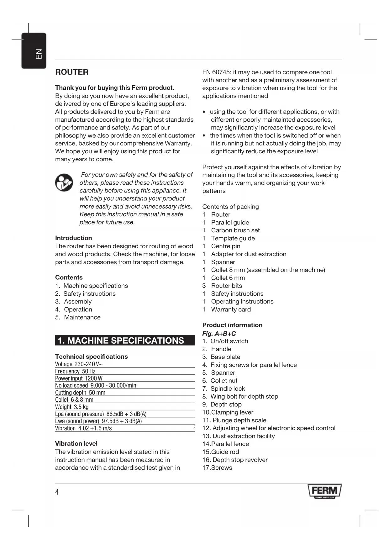
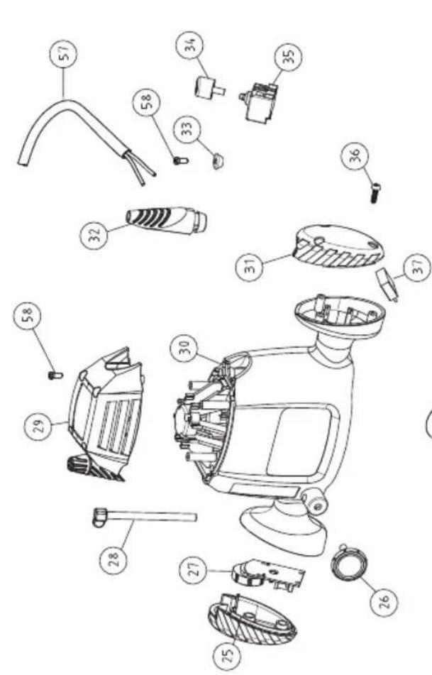
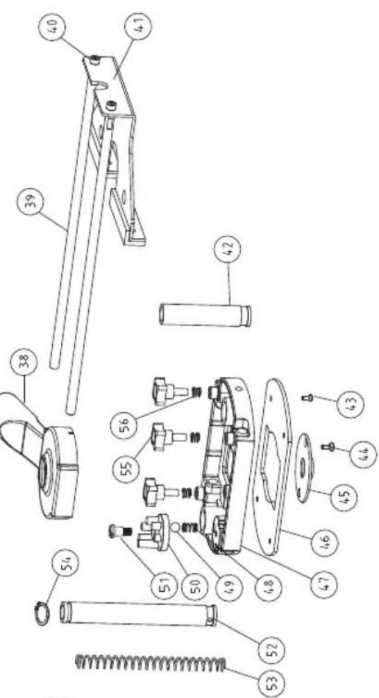
Spare parts list
PRM1021
| Article No. Description | Position no. | |
| 411029 Collet set 5|6 | ||
| 411030 Depth lock lever | 9..11 | |
| 411031 Rotor 18 | ||
| 411032 Carbon brush and holder set (2 pcs) 20|21 | ||
| 411033 Stator 22 | ||
| 411034 Bearing 608 23 | ||
| 411035 Main switch 34|35 | ||
| 411036 Dust extraction guard 38 | ||
| 411037 Parallel guide 39..41 | ||
| 411038 Depth stop revolver 48..51 | ||
| 411039 Parallel guide knob 55|56 | ||
| 411040 Center pin | ||
| 411041 Router bits (3 pcs) |
Exploded view
- Thank you for buying this Ferm product.
- Introduction
- Contents
- MACHINE SPECIFICATIONS
- Technical specifications
- Vibration level
- Contents of packing
- Product information
- Fig. A+B+C
- SAFETY INSTRUCTIONS
- The following symbols are used in these instructions for use:
- Additional safety instructions
- ASSEMBLY
- Router Bit Selection
- Mounting and removing cutters
- Fig. E
- Mounting the template guide
- Fig. C
- Mounting the adapter for dust extraction
- Fig. B+D
- OPERATION
- The ON/OFF switch
- Usage tips
- Speed Preselection
- Material Diameter Router bit Speed stages
- Height setting of the router column
- Fig. B
- Adjusting the routing depth
- Adjustment using the revolver-depth stop
- Using the centre pin
- Fig. G
- MAINTENANCE
- Cleaning
- Troubleshooting
- The operating switch is switched on, but the motor is not working
- Routerrunsslowly
- Excessive vibration
- Faults
- ENVIRONMENT
- WARRANTY
- OBERFRASE
- Vibrations excessives
- Pannes
- Nivo vibracija
- TEXHINUCKNE XAPAKTEPNUCTUKN
- TexHueeckne xapaKTepeNCTUKN
- YpOBeHb Bn6paUIM
- KOMNJIeKTHoCTb
- Hhopmaqna 6 n3deJnn
- Pnc. A + B + C
- YKA3AHNЯ NO TEXHnKE 6E3OJACHOCTN
- B daHHoH nHCTpyKcunn HcNoJIb3yIOTcneDyUOuNe 3HaKn:
- DOnOpHnTeIbHbIe npaBnla TexHnKn 6e30NaCHOCTn
- CBOPKA
- Bb6op hacaok facoHno-phiepHoro cTaHka
- YcTaHOBka N ydaJIeHne peKyuInx HacaIOK Pnc. E
- PerynpoBka Hapablaioe JInHeKu
- YcTaHOBKa HnpaBnaIooJe dIra 7a6JNoHa
- Pnc.C
- YcTaHOBka aAnTepa nbIeynIOBtEnr
- Pnc. B+D
- 4.3KcπJyATAUЯ
- BbIKJIOyateJIb NITAHN
- PekomeHdaun no nCnoB3ObaHnIO
- PpeBapnteIbHbI Bb6Op cKopoCTn
- Matern DnameTp hacaKcKopoctb
- HactpoJa BBICOTbIO OCHOBAHnA facoHO-Φpe3epHOrO CTaHka
- Pnc.B
- PerynnpOBKa rny6uHbI φpe3epoBaHn
- PerynipoBka c nomoob 6apa6bana- orpaHnUteIraLy6nHbI
- IcnoJb3OBAHne anphi
- Pnc. G
- OBCJNYXKUBAHNE
- OuNTka
- DnarHocTnka n ycTaPaeHne HncnPabHOcTei
- BbIKHouateIb HaxoIITcBO BKJIIOueHHOM
- noLoXeHn, Ho DbVaTeJIb He pa6oTaET
- 2ФacOHHO-Φpe3epHbI cTaHOK pa6oTaet MeJHeHHO
- 4pezmepnha Bn6paun
- HencnpabHoctn
- OKPYXIAOUIA CPEDA
- TAPAHNTY
- ФАСОНHO-ФPE3EPHи BEPCTAT
- JaKyemOBam 3a KyniBIO npOdyKTy KOMnaii Ferm.
- BVeEeHn
- 3mict
- TEXHIYHI XAPAKTEPNCTIKM MALUNHN
- TexhiHcneuΦikaui
- Pibehbbiopauii
- Bmictynakobkn
- IHCTPyKciI ⅢOIO Bc3NEKN
- Bux iHCTpykuiBX BUKOpNCTOBYIOTBc HAcTyNHi CmBOJn:
- DogaTKoBi iHCTpyKuIi 0do6e3neKn
- 3BOPKA
- Bn6ip BcTabOK facohho-epe3epHoro Bepctaty
- BcTaHOBHeHH Ta 3HimaHH Hpe3
- Man. E
- HaataybaHHa iHnnapaJIbHnx 6mexyBaivB
- BctaHOBHeHHHaNPabIauOoi wa6NoHy Man.C
- BctaHOBHeHH aanTepy dny nIOOBIOBAHH
- BUKOPNCTAHH
- Nepemkau Bk./BmK
- Iopadu odo BVkOpncTaHHa
- Bn6ip wbndkocti
- HajauTyBaHHa BnCOTN KOLOHn fpe3epHoro Bepctaty
- Man. B
- PerylIOBaHHrIINHnΦpe3epyBaHHr
- HaJauTyBaHn3 BnKOpNCTaHHaM6apab6aHnoro 06mexyBaayrIn6
- BukopncTaHHa WbOpH
- Man.G
- TEXHlUHe BCJnyOByBAHHa
- OuHn
- BnBJIeHHHeCnpaBHOcTei
- Nepemkaay 3haxoNTbcB noloxeHHI BkI., aIe DnurH He npaHoe
- 2ФacOHHO-Φpe3epHnBepTaT npaHOC nobilbHo
- 3HaMipHa Bi6paia
- DepeKTH
- CEPEIOBUN
- 「APAHTI
- POYTEP
- Zac euxapiotoue nou euiéaTe va ayopaoet auto to npoiov Tc Ferm.
- CbDpbXaHHe Ha onaKOBkata
- HhOpmaa3a HnCTpyMeHa
- ur.A + E + C
- 2.ИЗСКBAHЯ 3A TEXHINKA HA BE3ONACHOCT
- B HacToaTO pIbKOBoDCTBO Ha nOTpe6uTeJIe Ce IOL3BaT CJIeHNTE CMMBOJN:
- DonbHnTeJn npabJna 3a 6eJOnacha pa6ota
- MOHTAX
- I36op Ha HauKpaHnK 3a o6eppe3aTa.
- IocTabraHe n npemaxBaHe Ha peXeunTe HauKpaHnCn
- Φnε. E
- Perynpahe Ha Hacooybaaata JINHIA
- MOr. C
- NoctabrHe Ha aanTepa Ha npaxoyIOBtEnr nr,B + D
- TEXHINU ECKO OBCJNUXBAHE
- BkIIOUbaHe/V3KJIIOUbaHe Ha 3axpaHbAHeTo
- Ppenopbkn 3a pa6oTa
- PpeBapuTeIeH u36op Ha cKopoocT
- HactpoBbHe Ha BucOuHHa Ta Ha OCHOBaTa Ha 0pe3ata
- Φur.B
- Perynpane Ha nbl6uHaTa Ha ppe3oBaHe
- Perynpane c 6apa6aH-OrpaHnHTen Ha dbNoHHata
- N3noJ3BaHe Ha weHKeJIHHa 6oJT
- Φnr. G
- TEXHINUeCKO OBCJIyXBAHE
- NouchTaHe
- MnaHOCHTnKa NOTCTpaHraBaHa HEn3npabHOCTnte.
- KIIOUbTe B NOLOXeHne BKJI., Ho DnBraTeJrT He pa60Tu
- 06epfep3aTa pa6oTu 6abHo
- 3.CnHn Bn6paun
- Hen3npabHoctn
- 3AUNTA HA OKOJHATA CPEDA
- TAPAHIOHHYCIOBnA
- CE
- DECLARATION OF CONFORMITY
- PRM1021 - ROUTER
- Spare parts list
- Exploded view
Brand : Ferm
Model : PRM1021
Category : Milling machine