PRM1011 - Milling machine Ferm - Free user manual and instructions
Find the device manual for free PRM1011 Ferm in PDF.


| Brand | Ferm |
| Model | PRM1011 |
| Product type | Router (milling machine) |
| Supply voltage | 230 V |
| Frequency | 50 Hz |
| Power consumption | 1200 W |
| No-load speed | 9000 - 30000 rpm |
| Max. milling diameter | 30 mm |
| Milling depth | 30 mm |
| Clamping collet | 6 and 8 mm |
| Weight | 3.71 kg |
| Sound pressure level (Lpa) | 91 dB(A) |
| Sound power level (Lwa) | 102 dB(A) |
| Vibrations (left handle) | 1.4 m/s² |
| Vibrations (right handle) | 5.4 m/s² |
| Protection class | II (double insulation) |
| Electronic speed control | Yes, 6 levels |
| Package contents | Router, 6 router bits, parallel guide, template guide, dust extraction adapter, pin spanner, collets 6/8 mm, instruction manual, warranty certificate |
| Main functions | Milling wood, woody materials and plastics; fine depth adjustment; turret stop for 6 depths; spindle lock for bit change |
| Maintenance and cleaning | Regular cleaning with soft cloth; no lubrication necessary |
| Safety | Switch with lock; double insulation; immediate stop in case of fault |
| General information | Professional device for precision milling; warranty according to enclosed certificate |
Frequently Asked Questions - PRM1011 Ferm
User questions about PRM1011 Ferm
0 question about this device. Answer the ones you know or ask your own.
Ask a new question about this device
Download the instructions for your Milling machine in PDF format for free! Find your manual PRM1011 - Ferm and take your electronic device back in hand. On this page are published all the documents necessary for the use of your device. PRM1011 by Ferm.
USER MANUAL PRM1011 Ferm
Thank you for buying this Ferm product.
By doing so you now have an excellent product, delivered by one of Europeis leading suppliers. All products delivered to you by Ferm are manufactured according to the highest standards of performance and safety. As part of our philosophy we also provide an excellent customer service, backed by our comprehensive Warranty. We hope you will enjoy using this product for many years to come.
The numbers in the text refer to the diagrams on page 2-4.

Read the operating instructions carefully before using this device.
Familiarize yourself with its functions and basic operation. Service the device as per the instructions to ensure that it always functions properly. The operating instructions and the accompanying documentation must be kept in the vicinity of the device.
Contents
- Technical specifications
- Safety instructions
- Mounting accessoires
- Operation
- Maintenance
1. TECHNICAL SPECIFICATIONS
Machinedata
| Voltage 230 V | |
| Frequency 50 Hz | |
| Power input 1200 W | |
| No load speed/min 9000-30000 | |
| Max. cutter diameter 30 mm | |
| Cutting depth 30 mm | |
| Collet 6+8 mm | |
| Weight 3.71 kg | |
| Lpa (sound pressure) 91+3 dB(A) | |
| Lwa (sound power) 102+3 dB(A) | |
| Vibration left handle 1,4+1,5 m/s | 2 |
| Vibration right handle 5.4+1.5 m/s | 2 |
Vibration level
The vibration emission level stated in this instruction manual has been measured in
accordance with a standardised test given in EN 60745; it may be used to compare one tool with another and as a preliminary assessment of exposure to vibration when using the tool for the applications mentioned
- using the tool for different applications, or with different or poorly maintained accessories, may significantly increase the exposure level
- the times when the tool is switched off or when it is running but not actually doing the job, may significantly reduce the exposure level
Protect yourself against the effects of vibration by maintaining the tool and its accessories, keeping your hands warm, and organizing your work patterns
Package contents
1 Router
6 Cutters (router bits)
1 Parallel guide
1 Template guide
2 Screws
2 Nuts
1 Adapter for dust extraction
1 Dust tube
1 Wrench
1 6 mm Collet
1 8 mm Collet
1 Instruction manual
1 Guarantee card
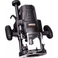
The router has been designed for professional routing of wood, wood products and plastics.

Check the machine, loose parts and accessories for transport damage.
Product information
Fig. A+C
- On/off switch
- Handle
- Base plate
- Fixing screws for parallel fence
- Safety catch
- Collet nut
-
Spindle lock
-
Cutting depth adjustment button
- Wing bolt for depth stop
- Depth stop
- Clamping lever
- Cutting depth scale
- Adjusting wheel for electronic speed controller
- Height adjustment button
- Cutting depth fine-tuning button
- Dust extraction facility
- Parallel fence ruler
- Zero mark
- Parallel fence
- Guide rod
- Depth stop revolver
2. SAFETY INSTRUCTIONS
Explanation of the symbols

Denotes risk of personal injury, loss of life or damage to the tool in case of non-observance of the instructions in this manual.

Indicates electrical shock hazard.

The number of revolution of the machine can be electronically set.

Wear ear and eye protection
The instructions must be kept in a safe place!
- Please check workpieces for any obstructions on the surface of the material, such as protruding nails etc., to protect the router head.
- Wait until the router has come to a complete stop before removing any blocked or routed material around the cutter. Use a long stick for this and not your finger.
- Please keep your hands away from the routing surface.
- Immediately switch off the tool as soon as it starts producing any unusual noise or starts vibrating excessively.
Electrical safety
When using electric machines always observe the safety regulations applicable in your country to reduce the risk of fire, electric shock and personal injury. Read the following safety instructions and also the enclosed safety instructions.

Always check that the power supply corresponds to the voltage on the rating plate.

Class II machine. Your machine is double insulated; therefore no earthwire is required.
Replacing cables or plugs
Immediately throw away old cables or plugs when they have been replaced by new ones. It is dangerous to insert the plug of a loose cable in the wall outlet.
Using extension cables
Only use an approved extension cable suitable for the power input of the machine. The minimum conductor size is 1.5 mm^2 . When using a cable reel always unwind the reel completely.
Immediately switch off the machine when:
Excessive sparking of the carbon brushes and • verticiliosis in the collector.
Interruption of the mains plug, mains lead or • mains lead damage.
Defect switch•
Smoke or stench of scorched isolation•
3. MOUNTING ACCESSORIES

Prior to mounting an accessory always unplug the tool.

Wait until the machine has come to a complete standstill and the cutter has cooled down before replacing a cutter.
Mounting and removing cutters
Fig. B
Only use cutters with a shaft diameter which corresponds with the size of the collet. Only use cutters which are suited for the maximum speed of the machine. The cutter diameter should not exceed the maximum diameter (see 'Technical specifications').
Press the spindle lock (7) and turn the collet nut (6) until it engages in the lock. Keep the spindle lock pressed during this procedure.
Open the collet nut using the wrench.
Place the cutter shaft in the collet.
Tighten the collet nut so that the cutter is locked properly.
Open the collet nut when you want to replace • a cutter.
Adjusting the parallel fence ruler
Fig. A+C
The parallel fence is a useful tool for precision routing at a fixed distance from the edge of the workpiece.
Place the desired cutter in the tool.
Loosen the clamping lever (11).•
Push the tool down until the cutter sticks out • from the base plate, then retighten the clamping lever (11).
Place the router onto the workpiece in such a • that the cutter touches the side of the workpiece. Please ensure that the furthest protruding part of the cutter touches the workpiece (by turning the cutter if necessary).
Slide the provided guide rods (20) into the • appropriate holes.
Slide the parallel fence onto the mounted rods until it is in full contact with the workpiece. The zero-position is now set.
Attach the ruler (17) to the rod of the parallel guide. The zero on the ruler must be aligned with the zero mark (18).
Loosen the parallel fence fixing screw (4) and move the fence until the desired setting has been reached. Important: when adjusting the parallel fence, please take into account the diameter of the cutter.
Retighten the fixing screw (4).
Mounting the guide bush
Fig. D
The guide bush is a handy aid for cutting a pattern.
Mount the guide bush (23) on the router base • (3) using the screws (22).
Mounting the adapter for dust extraction
Fig. E+F
Use the dust adapter for the extraction of dust.
Mount the dust adapter (24) with the screws • (22) on the cutter sole (3).
- Place the dust tube (25) in the dust output (16).
- Place the tube of your vacuum cleaner on the dust tube (25).

Keep the outlet of the machine behind the machine for a good view on the workpiece.
4. OPERATION
The on/off switch
Fig. A
- To switch on the tool, press and hold the on/off switch (1). If you release the on/off switch (1), the tool will be switched off.
Switch locking mechanism
You can lock the on/off switch by pressing the on/off switch (1) and then button (5). The switch lock can be released by briefly pressing the on/off switch (1).

Always select a low speed for cutting plastic workpieces.
Do not put the machine down when the motor is still running. Do not place the machine on a dusty surface. Dust particles may enter the mechanism.

Always observe the safety instructions and applicable regulations.
Operation
Hold the machine in rest position on the workpiece when switching the machine on or off. The cutter in the collet may damage the workpiece.
- Clamp the workpiece and make sure that the workpiece cannot slide from under the machine during the cutting activities.
- Hold the machine firmly and move it evenly over the workpiece. Do not force the machine.
- Only use cutters which do not show any signs of wear. Worn cutters have a negative effect on the efficiency of the machine.
• Always switch off the machine first before removing the plug from the wall socket.
Speed preselection
The required speed can be preselected with
the thumbwheel (13). Also during running the rotational speed can be adjusted.
1 - 2 = low speed
3 - 4 = medium speed
5 - 6 = high speed
Max = maximum speed
The required speed depends on the material and can be determined by practical testing. Furthermore router bits with a large diameter need a lower rotational speed.
Material Diameter Speed stages router bit
| Hardwood > 20 mm 1 - 2 |
| 10 - 20 mm 3 - 4 |
| < 10 mm 5 - max |
| Softwood >20 mm 1 - 3 |
| 10 - 20 mm 3 - 6 |
| < 10 mm 5 - max |
| Aluminium > 15 mm 1 |
| < 15 mm 1 - 2 |
| Plastic > 15 mm 1 - 2 |
| < 15 mm 2 - 3 |
After longer periods of working at low speed, allow the machine to cool down by running it for a few minutes at high speed with no load.
Height setting of the router column
Fig. G
Button (14) is used to set the maximum height of the router.
The cutting depth is then fixed. This is usually necessary when using the tool on a special router table.
Rough setting:
Loosen the clamping lever (11). The router can then be pushed down against the spring force.
Hold button (14) between your thumb and • index finger.
Push the grey button (14) and use your other hand to push the router down at the same time.
Release the button. The router is now locked • and will no longer return to its original position.
Fine adjustment:
Turn button (14) clockwise. This causes the router column to slowly move down.
- Turn button (14) counter-clockwise. This causes the router column to slowly move up.
Setting of the cutting depth
Fig. G
The cutting depth can be adjusted by using buttons 8, 9, 11 and 15. If the cutting depth is set correctly, the groove in question can be routed accurately to within 0.1 mm.
Preparation:
- Place the desired cutter in the tool.
- Loosen the clamping lever (11). The router can then be pushed down against the spring force.
- Push the tool down until the cutter touches the workpiece, then relock it using the clamping lever (11).
- Loosen button 9 (counter-clockwise).
- Set button 15 to zero.
- Use button 8 to set the depth all the way down.
- Tighten button 9 (clockwise). The cutting depth is now set to precisely 0 mm.
Rough setting:
- Read the value from the scale (12).
- Loosen button 9 (counter-clockwise).
- Turn button 8 and re-read the value from the scale. The difference between the two values is the cutting depth setting.
For example: If the value on the scale (12) is 8.5 in the zero-setting and the value is 7.0 after button (8) has been turned, then the cutting depth has been set to 1.5 cm.
• Retighten button 9 (clockwise).
Fine adjustment:
- Loosen button 9 (counter-clockwise).
- The top button (15) is still set to zero. Give this button a full counter-clockwise turn, until it is back in the zero position. The cutting depth is now 1.0 mm less.
- If required, the cutting depth can be set accurately to within 0.1 mm.
- Retighten button 9.
Adjustment using the revolver-depth stop
The revolver-depth stop enables you to quickly choose between six different cutting depths.
These are also determined by the adjustment of the depth stop (10).
Adjust the required cutting depth by rotating the revolver-depth stop (21).
5. MAINTENANCE

Make sure that the machine is not live when carrying out maintenance work on the motor.
This machine has been designed to operate over a long period of time with a minimum of maintenance. Continuous satisfactory operation depends upon proper machine care and regular cleaning.
Malfunction
Should the machine fail to function correctly, a number of possible causes and the appropriate solutions are given below:

Repairs and servicing should only be carried out by a qualified technician or service firm.
Cleaning
Regularly clean the device's casing with a soft cloth, preferably after each use. Keep the fan slits free of dust and dirt. Remove stubborn dirt using a soft cloth, dampened with soapy water. Do not use solvents such as benzene, alcohol, ammonia, etc, which might damage the plastic parts.
Lubrication
This device does not need any additional lubrication.
Defects
If a defect appears due to a part wearing out, please contact the service center on the warranty card. Separately you will find an exploded view showing the parts that can be ordered.
Environment
To prevent damage during transport, the appliance is delivered in a solid packaging which consists largely of reusable material. Therefore please make use of options for recycling the packaging.

Damaged and/or disposed of electrical or electronic devices must be dropped off at recycling stations intended for that purpose.
Warranty
Read the warranty conditions on the separately supplied warranty card.
Wear of the cutter is not covered by the guarantee.
OBERFRÄSE
Storing in de netstekker, netsnoer of • snoerbeschadiging.
Defecte schakelaar.
Stille inn fresebybden
Fig. G
Fresedybden kan justeres med knappene 8, 9, 11 og 15. Hvis fresedybden er riktig innstilt, kan det aktuelle sporet fresse med en nøyaktighet på 0,1 mm.
Klargjøring:
,·s<·s.


DECLARATION OF CONFORMITY
(GB) We declare under our sole responsibility that this product is in conformity and accordance with the following standards and regulations:
(DE) Der Hersteller erklärt eigenverantwortlich, dass dieses Produkt den folgenden Standards und Vorschriften entspricht:
(NL) Wij verklaren onder onze volledige verantwoordelijk heid dat dit product voldoet aan, en in overeenstem ming is met, de volgende standaarden en reguleringen:
(FR) Nous déclarons sous notre seule responsabilité que ce produit est conforme aux standards et directives suivants:
(ES) Declaramos bajo nuestra exclusiva responsabilidad que este producto cumple con las siguientes normas y estándares de funcionamiento:
(PT) Declaramos por nossa total responsabilida-de que este produto está em conformidade e cumpre as normas e regulamentações que se seguem:
(IT) Dichiariamo, sotto la nostra responsabilità, che questo prodotto è conforme alle normative e ai regolamenti seguenti:
(SV) Vi garanterar på eget ansvar att denna produkt upp fyller och följer följande standarder och bestämmelser:
(FI) Vakuutamme yksinomaan omalla vastuullamme, että tämä tuote täyttää seuraavat standardit ja säädökset:
(NO) Vi erklærer under vårt eget ansvar at dette produktet er i samsvar med følgende standarder og regler:
(DA) Vi erklærer under eget ansvar, at dette produkt er i overensstemmelse med følgende standarder og bestemmelser:
(HU) Felelősségünk teljes tudatában kijelentjük, hogy ez a termék teljes mértékben megfelel az alábbi szabványoknak és előírásoknak:
(CS) Na naši vlastní zodpovědnost prohlašujeme, že je tento výrobek v souladu s následujícími standardy a normami:
(SK) Vyhlasujeme na našu výhradnú zodpovednosť, že tento výrobok je v zhode a súlade s nasledujúcimi normami a predpismi:
(SL) S polno odgovornostjo izjavljamo, da je ta izdelek v skladu in da odgovarja naslednjim standardom terpredpisom:
(PL) Deklarujemy na własną odpowiedzialność, że ten produkt spełnia wymogi zawarte w następujących normach i przepisach:
(LT) Prisiimdami visą atsakomybę deklaruojame, kad šis gaminys atitinka žemiau paminėtus standartus arba nuostatus:
(LV) Apgalvojam ar visu atbildību, ka šis produkts ir saskaņā un atbilst sekojošiem standartiem un nolikumiem:
(ET) Deklareerime meie ainuvastutusel, et see toode on vastavuses ja kooskõlas järgmiste standardite ja määrustega:
(RO) Declarăm prin aceasta cu răspunderea deplină că produsul acesta este în conformitate cu următoarele standarde sau directive:
(HR) Izjavljujemo pod vlastitom odgovornol,šu da je strojem ukladan sa slijedešim standardima ili standardiziranim dokumentima i u skladu sa odredbama:
(SR) Pod punom odgovornošću izjavljujemo da je usaglašen sa sledećim standardima ili normama:
(RU) Под свою ответственность заявляем, что данное изделие соответствует следующим стандартам и нормам:
(UK) На свою власну відповідальність заявляємо, що дане обладнання відповідає наступним стандартам і нормативам:
(EL) Δηλώνουμε υπεύθυνα ότι προϊόν αυτό συμφωνεί και τηρεί τους παρακάτω κανονισμο ύς και πρότυπα:
(BG) Ние заявяваме, по своя собствена отговорност, че този продукт отговаря на следните стандарти и директиви
EN 55014-1, EN 55014-2, EN 60745-1, EN 60745-2-6, EN 61000-3-2, EN 61000-3-3
2006/42/EC, 2006/95/EC, 2004/108/EC, 2002/96/EC, 2006/95/EC
Zwolle, 01-01-2010
J.A. Bakker-van logen

CEO Ferm BV
It is our policy to continuously improve our
products and we therefore reserve the right to change the product specification without prior notice.
Ferm BV • Lingenstraat 6 • 8028 PM • Zwolle The Netherlands
Spare parts list
Position Description No.
| 2 Base plate 302124 | |
| 6+7 Locking knob with spring 302112 | |
| 8 Dust extraction 302111 | |
| 21 Collet nut 302125 | |
| 22 Collet 6 mm 302126 | |
| 22 Collet 8 mm 302127 | |
| 41 Lever 302129 | |
| 51 Switch 302130 | |
| 63 Brush cover 302131 | |
| 64 Carbon brush set (2 pcs) 302123 | |
| 66 Brush holder 302132 | |
| 94 Parallel guide | 302114 |
| 95+97(2X) Guiding rod (set) | 302005 |
| 99 Ruler | 302121 |
| 100 Spanner | 302133 |
| 101 Template ring | 302122 |
Exploded view

- Thank you for buying this Ferm product.
- The numbers in the text refer to the diagrams on page 2-4.
- Contents
- TECHNICAL SPECIFICATIONS
- Machinedata
- Vibration level
- Package contents
- Product information
- Fig. A+C
- SAFETY INSTRUCTIONS
- Explanation of the symbols
- The instructions must be kept in a safe place!
- Electrical safety
- Replacing cables or plugs
- Using extension cables
- MOUNTING ACCESSORIES
- Mounting and removing cutters
- Fig. B
- Adjusting the parallel fence ruler
- Mounting the guide bush
- Fig. D
- Mounting the adapter for dust extraction
- Fig. E+F
- OPERATION
- The on/off switch
- Fig. A
- Switch locking mechanism
- Operation
- Height setting of the router column
- Fig. G
- Rough setting:
- Fine adjustment:
- Setting of the cutting depth
- Preparation:
- Adjustment using the revolver-depth stop
- MAINTENANCE
- Malfunction
- Cleaning
- Lubrication
- Defects
- Environment
- Warranty
- OBERFRÄSE
- Stille inn fresebybden
- Klargjøring:
- DECLARATION OF CONFORMITY
- EN 55014-1, EN 55014-2, EN 60745-1, EN 60745-2-6, EN 61000-3-2, EN 61000-3-3
- Spare parts list
Brand : Ferm
Model : PRM1011
Category : Milling machine