PRM1001 - Milling machine Ferm - Free user manual and instructions
Find the device manual for free PRM1001 Ferm in PDF.


| Brand | Ferm |
| Model | PRM1001 |
| Product Type | Router (Milling Machine) |
| Voltage | 230 V~ |
| Frequency | 50 Hz |
| Power Input | 550 W |
| No Load Speed | 8000-32000 /min |
| Max. Cutter Diameter | 30 mm |
| Cutting Depth | 35 mm |
| Collet Sizes | 6 mm (1/4"), 8 mm |
| Weight | 3.25 kg |
| Sound Pressure Level (Lpa) | 81.3 dB(A) |
| Sound Power Level (Lwa) | 94.3 dB(A) |
| Vibration Value | <4.0 m/s² |
| Fuse | 10 A (230 V machines) |
| Insulation | Double insulated (no earth wire required) |
| Speed Control | Electronic (adjusting wheel) |
| Depth Adjustment | Scale and revolver-depth stop (3 positions) |
| Parallel Guide | Included, adjustable |
| Dust Extraction Adapter | Included (mounts on base) |
| Package Contents | Router, cutter, parallel guide, screws, collets (6mm & 8mm), spanners, hex key, manual, safety instructions, guarantee card |
| Maintenance | Regular cleaning with soft cloth; no additional lubrication required |
| Safety Features | On/off switch with lock, double insulation, safety instructions included |
| Application | Professional routing of wood, wood products and plastics |
Frequently Asked Questions - PRM1001 Ferm
User questions about PRM1001 Ferm
0 question about this device. Answer the ones you know or ask your own.
Ask a new question about this device
Download the instructions for your Milling machine in PDF format for free! Find your manual PRM1001 - Ferm and take your electronic device back in hand. On this page are published all the documents necessary for the use of your device. PRM1001 by Ferm.
USER MANUAL PRM1001 Ferm
natural_image
Technical line drawing of a mechanical device with dual supports and a cylindrical top (no text or symbols)FBF-6E
Ferm®


ROUTER
The following symbols are used throughout this manual:

Denotes risk of personal injury, loss of life or damage to the tool in case of non-observance of actions in this manual.

Denotes risk of electric shock.
Carefully read this manual before using the machine. Make sure that you know how the machine functions and how to operate it. Maintain the machine in accordance with the instructions to make sure it functions properly. Keep this manual and the enclosed documentation with the machine.
SAFETY INSTRUCTIONS
When using electric machines always observe the safety regulations applicable in your country to reduce the risk of fire, electric shock and personal injury. Read the following safety instructions and also the enclosed safety instructions.
Keep these instructions in a safe place!
- Check workpieces for any protruding nails etc. and remove these.
- Keep your hands away from the surface to be cut.
TECHNICAL SPECIFICATIONS
| Voltage 230 V~Frequency 50 HzPower input 550 WNo load speed 8000-32000/minMax. cutter diameter 30 mmCutting depth 35 mmCollet 6 mmWeightLpa (sound pressure)Lwa (sound power)Vibration valueFuses 230 V machines | 3.25 kg81.3 dB(A)94.3 dB(A)<4.0m/s ^2 10 A |
Electrical safety

Always check that the power supply corresponds to the voltage on the rating plate.

Your machine is double insulated in accordance with EN 50144; therefore no earthwire is required.
Replacing cables or plugs
Immediately throw away old cables or plugs when they have been replaced by new ones. It is dangerous to insert the plug of a loose cable in the wall outlet.
Using extension cables
Only use an approved extension cable suitable for the power input of the machine. The minimum conductor size is 1.5 mm². When using a cable reel always unwind the reel completely.
PACKAGE CONTENTS
1 router
1 cutter
1 parallelguide
2 screws
1 6mmcollet(1/4")
1 8mmcollet
2 open-endedspanners
1 hexagonalkey
1 instruction manual
1 safety instructions
1 guarantee card
Check the machine, loose parts and accessories for transport damage.
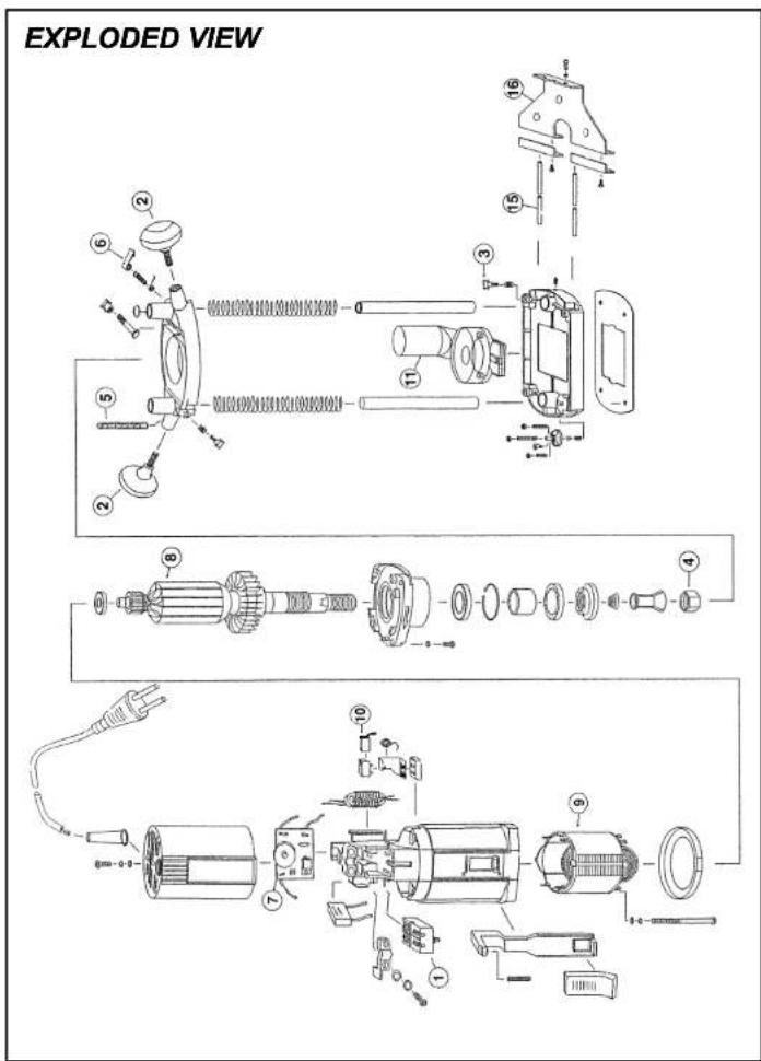
Fig. A.
This machine has been designed for professional routing of wood, wood products and plastics.
1 on/off switch
2 machine clamp screw
3 clamping lever for depth adjustment
4 handle
5. colletbracket
6 colletnut
7 routerbase
8 opening for parallel guide
9 locking bolt for parallel guide
10 revolver-depth stop
1 scale cutting depth
2 locking bolt depth stop
13 adjusting wheel electronic speed control
MOUNTING ACCESSORIES

natural_image
Mechanical device diagram showing rotational components and mounting base (no text or labels)Fig. B.

Prior to mounting an accessory always unplug the tool.
Mounting and removing cutters.
Only use cutters with a shaft diameter which corresponds with the size of the collet. Only use cutters which are suited for the maximum speed of the machine. The cutter diameter should not exceed the maximum diameter (see 'Technical specifications').
- Place an open-ended spanner on the collet bracket and use the second spanner to loosen the collet nut.
- Place the cutter shaft in the collet
- Tighten the collet nut so that the cutter is locked properly.
- Open the collet nut when you want to replace a cutter.

Wait until the machine has come to a complete standstill and the cutter has cooled down before a cutter.
Mounting and adjusting the parallel guide
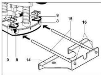
Fig. C
The parallel guide is a handy aid when working on narrow workpieces.
- Mount the parallel guide. Attach the guide rods (15) on the frame (14) using the bolts (16).
- Loosen the locking bolts (9) and slide the guide rods in the openings (8).
- Adjust the parallel guide to the desired guide distance.
- Tighten the locking bolts again.
Mounting the adapter for dust extraction.

Fig. D
Use the adapter for extracting dust.
- Loosen the machine clamp screw (2) and remove the machine from its base.
- Mount the adapter for dust extraction (18) on the router base (7) using the screws (17) and nuts (19).
- Replace the maschine into the base.
- Place a vacuum cleaner nozzle on the adapter outlet.

Keep the outlet of the machine behind the machine for a good view on the workpiece.
OPERATION

Always observe the safety instructions and applicable regulations.
Hold the machine in rest position on the workpiece when switching the machine on or off. The cutter in the collet may damage the workpiece.
- Clamp the workpiece and make sure that the workpiece cannot slide from under the machine during the cutting activities.
- Hold the machine firmly and move it evenly over the workpiece. Do not force the machine.
- Only use cutters which do not show any signs of wear.
Worn cutters have a negative effect on the efficiency of the machine.
• Always switch off the machine first before removing the plug from the wall socket.
VEDLIGEHOLDELSE

nikken.
Adjusting the cutting depth

Fig. E
The cutting depth can be adjusted in two ways.
Adjustment using the scale
• Loosen the locking bolt of the depth stop (12).
- Release clamping lever (3) and press the machine so far down until the cutter touches the workpiece.
• Tighten the clamping lever again.
- Set the desired cutting depth using the graduated scales (11) and then tighten the clamp screw.
Adjustment using the revolver-depth stop
The revolver-depth stop enables you to quickly choose between three different cutting depths. These are also determined by the adjustment of the depth scale (11).
- Adjust the required cutting depth by the three screws on the revolver-depth stop (10).
Switching on and off (Fig. A).
- Depress the on/off switch (1) to switch the machine on. Then push the switch through its resistance to lock the switch in the on position. The cutter speed can be adjusted by means of the adjusting wheel (13).
- Release the on/off switch to switch the machine off or push the switch again when it is in locked position.

Always select a low speed for cutting plastic workpieces.
Do not put the machine down when the motor is still running. Do not place the machine on a dusty surface. Dust particles may enter the mechanism.
MAINTENANCE
Make sure that the machine is not live when carrying out maintenance work on the motor.
The Ferm machines have been designed to operate over a long period of time with a minimum of maintenance. Continuous satisfactory operation depends upon proper machine care and regular cleaning.
Cleaning
Regularly clean the machine housing with a soft cloth, preferably after each use. Keep the ventilation slots free from dust and dirt.
If the dirt does not come off use a soft cloth moistened with soapy water. Never use solvents such as petrol, alcohol, ammonia water, etc. These solvents may damage the plastic parts.
Lubrication
The machine requires no additional lubrication.
Faults
Should a fault occur, e.g. after wear of a part, please contact your local Ferm dealer.
In the back of this manual you find an exploded view showing the parts that can be ordered.
ENVIRONMENT
In order to prevent the machine from damage during transport, it is delivered in a sturdy packaging. Most of the packaging materials can be recycled. Take these materials to the appropriate recycling locations.
Take your unwanted machines to your local Ferm-dealer. Here they will be disposed of in an environmentally safe way.
GUARANTEE
The guarantee conditions can be found on the separately enclosed guarantee card.
C ∈ DECLARATION OF CONFORMITY (GB)
We declare under our sole responsibility that this product is in conformity with the following standards or standardized documents
in accordance with the regulations.
98/37EEC, 73/23EEC, 89/336EEC
from 01-11-1999
GENEMUIDEN NL
G.M. Ensing
Quality department


Deutsch
FBF-6E OBERFRÄSE
natural_image
Technical line drawing of a mechanical device with rotating arms and base mount (no text or symbols)Fig. B.
Fig. C.
Abb. A.
natural_image
Mechanical assembly diagram showing a rotating device with springs and gears (no text or labels)Abb. B

Abb.C
Fig. A.
ERKLÆRING AV ANSVARSFORHOLD (N)
98/37EEC 73/23EEC 89/336EEC
fra 01-11-1999 GENEMUIDEN NL G.M. Ensing Quality department


OVERFLADEFRÆSER
98/37EEC 73/23EEC 89/336EEC
ab 01-11-1999 GENEMUIDEN NL G.M. Ensing Quality department

NL Nederlands
BOVENFREES
Fig. C
Fig. D
Fig. A.
natural_image
Technical line drawing of a mechanical device with rotating arms and adjustment knobs (no text or symbols)Fig. B
Fig. C
Fig. A.
natural_image
Mechanical device diagram showing rotating components and shafts (no text or labels)Fig. B.
Fig. D
Kuva C
The parallel guide is a handy aid when working on narrow workpieces.
Kuva D
L'emballage contient:
INFORMATION SUR LE PRODUIT

Fig. A.
natural_image
Technical line drawing of a mechanical device with rotating arms and adjustment knobs (no text or symbols)Fig. B
KuvaA.
natural_image
Mechanical assembly diagram showing a rotating device with springs and gears (no text or labels)Kuva B.
Fig. C
Fig. D
98/37EEC 73/23EEC 89/336EEC
fràn 01-11-1999
GENEMUIDEN NL
G.M. Ensing
Quality department

Fig. D
C ∈ DÉCLARATION DE CONFORMITÉ (F)
98/37EEC 73/23EEC 89/336EEC
dès 01-11-1999 GENEMUIDEN NL G.M. Ensing Quality department

S Svenska
ÖVERFRÄS
Fig. A.
natural_image
Technical line drawing of a mechanical device with rotating arms and adjustment knobs (no text or symbols)Fig.B
Fig. C
- ROUTER
- SAFETY INSTRUCTIONS
- Electrical safety
- Replacing cables or plugs
- Using extension cables
- PACKAGE CONTENTS
- Mounting and removing cutters.
- OPERATION
- VEDLIGEHOLDELSE
- Adjustment using the scale
- Adjustment using the revolver-depth stop
- Switching on and off (Fig. A).
- MAINTENANCE
- Cleaning
- Lubrication
- Faults
- ENVIRONMENT
- GUARANTEE
- C ∈ DECLARATION OF CONFORMITY (GB)
- Deutsch
- FBF-6E OBERFRÄSE
- ERKLÆRING AV ANSVARSFORHOLD (N)
- OVERFLADEFRÆSER
- NL Nederlands
- BOVENFREES
- fràn 01-11-1999
- GENEMUIDEN NL
- C ∈ DÉCLARATION DE CONFORMITÉ (F)
- S Svenska
- ÖVERFRÄS
Brand : Ferm
Model : PRM1001
Category : Milling machine