
GLM 50 C Professional - Rangefinder BOSCH - Free user manual and instructions
Find the device manual for free GLM 50 C Professional BOSCH in PDF.
| Product Type | Laser Distance Measurer |
| Brand | Bosch |
| Model | GLM 50 C Professional |
| Dimensions (L × W × H) | 106 × 45 × 24 mm |
| Weight (according to EPTA 01:2014) | 0.10 kg |
| Power supply | 2 AAA batteries or rechargeable batteries (1.5 V LR03 / 1.2 V HR03) |
| Battery life (individual measurements) | up to 10,000 measurements |
| Typical range | 0.05 to 50 m |
| Typical measurement accuracy | ±1.5 mm |
| Smallest display unit | 0.1 mm |
| Inclination measurement range | 0°-360° (4×90°) |
| Typical inclination accuracy | ±0.2° |
| Laser class | 2 |
| Laser type | 635 nm, <1 mW |
| Data transmission | Bluetooth® 4.0 (Classic and Low Energy) |
| Measurement functions | Length, area, volume, indirect, stakeout, continuous measurement, inclination, electronic level |
| Protection rating | IP54 (dust and water splash protection) |
| Operating temperature | -10 °C to +45 °C |
| Storage temperature | -20 °C to +70 °C |
| Tripod thread | 1/4" |
| Maintenance | Clean with a soft, dry cloth. Do not use harsh chemicals. |
| Safety | Do not look into the laser beam. Avoid any modification of the laser. Use only original spare parts. |
| Repairability | Have repairs done only by qualified personnel using original parts. |
Frequently Asked Questions - GLM 50 C Professional BOSCH
User questions about GLM 50 C Professional BOSCH
0 question about this device. Answer the ones you know or ask your own.
Ask a new question about this device
Download the instructions for your Rangefinder in PDF format for free! Find your manual GLM 50 C Professional - BOSCH and take your electronic device back in hand. On this page are published all the documents necessary for the use of your device. GLM 50 C Professional by BOSCH.
USER MANUAL GLM 50 C Professional BOSCH
OBD DOKU-44928-003.fm Page 1 Thursday, November 26, 2015 10:45 AM
GLM 50 C Professional
Robert Bosch GmbH
Power Tools Division
70764 Leinfelden-Echterdingen
GERMANY
www.bosch-pt.com
1609 92A 1RR (2015.11) O/571 EURO

1609 92A 1RR
mkOpHHHnHOynaICBO3pa60ra
sr Originalno uputstvo za rad
sIzyirna nayodila
hr Originalne uppute za rad
Laser Radiation Do not stare into beam Class 2 laser product
All instructions must be read and observed in order to work safely with the measuring tool. The integrated protections in the measuring tool may be compromised if the measuring tool is not used in accordance with the instructions provided. Never make warning signs on the measuring tool unrecognisable. STORE THESE IN
STRICTIONS IN A SAFE PLACE AND INCLUDE THEM WITH THE MEASURING TOOL WHEN GIVING IT TO A THIRD PARTY.
- Caution - The use of other operating or adjusting equipment or the application of other processing methods than those mentioned here can lead to dangerous radiation exposure.
The measuring tool is provided with a warning label (marked with number 12 in the representation of the measuring tool on the graphics page).
IEC60825-1:2014 <1mW, 635 nm
Laser Radiation Do not stare into beam Class 2 laser product
If the text of the warning label is not in your national language, stick the provided warning label in your national language over it before operating for the first time.

Do not direct the laser beam at persons or animals and do not stare into the direct or reflected laser beam yourself, not even from a distance. You could blind somebody, cause accidents or damage your eyes.
If laser radiation strikes your eye, you must deliberately close your eyes and immediately turn your head away from the beam.
Do not make any modifications to the laser equipment.
- Do not use the laser viewing glasses as safety goggles. The laser viewing glasses are used for improved visualisation of the laser beam, but they do not protect against laser radiation.
- Do not use the laser viewing glasses as sun glasses or in traffic. The laser viewing glasses do not afford complete UV protection and reduce colour perception.
1609 92A 1RR|(26.11.15) Bosch Power Tools


English | 29
Have the measuring tool repaired only through qualified specialists using original spare parts. This ensures that the safety of the measuring tool is maintained.
- Do not allow children to use the laser measuring tool without supervision. They could unintentionally blind other persons or themselves.
- Do not operate the measuring tool in explosive environments, such as in the presence of flammable liquids, gases or dusts. Sparks can be created in the measuring tool which may ignite the dust or fumes.
- Caution! When using the measuring tool with Bluetooth®, interference with other devices and systems, airplanes and medical devices (e.g., cardiac pacemakers, hearing aids) may occur. Also, the possibility of humans and animals in direct vicinity being harmed cannot be completely exempt. Do not use the measuring tool with Bluetooth® in the vicinity of medical devices, petrol stations, chemical plants, areas where there is danger of explosion, and areas subject to blasting. Do not use the measuring tool with Bluetooth® in airplanes. Avoid operation in direct vicinity of the body over longer periods.
The Bluetooth® word mark and logos are registered trademarks owned by Bluetooth SIG, Inc. and any use of such marks by Robert Bosch GmbH is under license.
Product Description and Specifications
Please unfold the fold-out page with the representation of the measuring tool and leave it unfolded while reading the operating instructions.
Intended Use
The measuring tool is intended for measuring distances, lengths, heights, clearances and inclines, and for calculating areas and volumes.
The measuring results can be transferred to other devices via Bluetooth®.
Technical Data
| Digital Laser Measure GLM 50 C | |
| Article number | 3601K72C.. |
| Measuring range (typical) | 0.05-50 mA) |
| Measuring range (typical under unfavourable conditions) | 20 mB) |
| Measuring accuracy (typical) ±1.5mm | A) |
Bosch Power Tools 1609 92A 1RR| (26.11.15)

30 | English
| Digital Laser Measure | GLM 50 C |
| Measuring accuracy (typical under unfavourable conditions) | ±3.0mmB) |
| Lowest indication unit 0.1 mm | |
| Indirect Distance Measurement and Vial | |
| Measuring range 0°-360° (4x90°) | |
| Inclination measurement | |
| Measuring range 0°-360° (4x90°) | |
| Measuring accuracy (typical) | ±0.2(C)/D)/(I) |
| Lowest indication unit 0.1° | |
| General | |
| Operating temperature -10 °C...+45 °C | E) |
| Storage temperature -20 °C...+70 °C | |
| Relative air humidity, max. | 90 % |
| Laser class | 2 |
| Laser type | 635 nm, <1 mW |
| Laser beam diameter (at 25 °C) approx. | |
| - at 10 m distance | 9 mmD) |
| - at 50 m distance | 45 mmD) |
| Automatic switch-off after approx. | |
| - L as r | 20 s |
| - Measuring tool (without measurement) | 5 minH) |
| Weight according to EPTA-Procedure 01:2014 0.10 kg | |
| Dimensions | 10 6 x 45 x 24 mm |
| Degree of protection | IP 54 (dust and splash proof)F) |
| Batteries | 2 x 1.5 VLR03 (AAA) |
| Rechargeable batteries | 2 x 1.2 VHR03 (AAA) |
| Battery life, approximately | |
| - Individual measurements | 10000H) |
| - Continuous measurement | 2.5 hH) |
| Setting the unit of measure | m, ft, in |
| Data transmission | |
| Bluetooth® | Bluetooth® 4.0 (Classic and Low Energy)G) |
1609 92A 1RR| (26.11.15) Bosch Power Tools


English | 31
A) For measurements from the rear measuring tool edge, weak backlighting and 25^ operating temperature are applicable for high reflectivity of the target (e.g. a white-painted wall). In addition, a deviation influence of ± 0.05mm / m must be taken into account.
B) For measurements from the rear measuring tool edge, applies to high reflectivity of the target (e.g. white cardboard), strong backlighting and -10^ to +45^ operating temperature. In addition, a deviation influence of ± 0.15mm / m must be taken into account.
C) After calibration at 0^ and 90^ with an additional grade error of ± 0.01^ /degree to 45^ (max.).
D) At 25^ operating temperature
E) In the continuous measurement function, the maximum operating temperature is +40^ .
F) except battery compartment
G) For Bluetooth® low energy devices, establishing a connection may not be possible, depending on model and operating system. Bluetooth® devices must support the SPP profile.
H) Bluetooth® deactivated
1) The left-hand side of the measuring tool serves as the reference level for grade measurement.
The measuring tool can be clearly identified with the serial number 11 on the type plate.
Declaration of Conformity
C
We declare under our sole responsibility that the product described under "Technical Data" complies with all applicable provisions of the directives 1999/5/EC and 2011/65/EU including their amendments and is in conformity with the following standards: EN 61010-1: 2010-10, EN 60825-1: 2014-08,
EN 300 328 V1.8.1: 2012-06, EN 301 489-1 V1.8.1: 2008-04, EN 301 489-1 V1.9.2: 2011-09, EN 301 489-17 V2.2.1: 2012-EN 62479: 2010-09, EN 50581: 2012.
Technical documents at: Robert Bosch GmbH, PT/ETM9, 70764 Leinfelden-Echterdingen, GERMANY
Henk Becker Helmut Heinzelmann
Executive Vice President Head of Product Certification
Engineering PT/ETM9

S BCD = S COD + S BDO - S BOC
i.v. h = u
Robert Bosch GmbH, Power Tools Division 70764 Leinfelden-Echterdingen, GERMANY Leinfelden, 10.11.2015


Bosch Power Tools 1609 92A 1RR| (26.11.15)


32 | English
Product Features
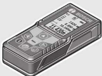
The numbering of the product features shown refers to the illustration of the measuring tool on the graphic page.
4 Button for selection of the reference level
1 Display
2 Measuring button[ ]
3 Plus button[+]
5 On/Off button[]
6 Bluetooth® button
7 Function button[Func]
8 Minus button[-]
9 Battery lid
10 Latch of battery lid
11 Serial number
12 Laser warning label
13 1/4"- Tripod socket
14 Reception lens
15 Laser beam outlet
16 Protective pouch
17 Laser target plate
18 Laser viewing glasses
19 Tripod*
- The accessories illustrated or described are not included as standard delivery.
Display elements (selection)
a Status Bluetooth®

Bluetooth® activated, no connection established

Bluetooth® activated, connection established
b Measurement reference level
c Battery indicator
d Measured-value lines
e Result line
f Measuring functions
g Display tilt angle
h Status bar
i Basic configurations
1609 92A 1RR| (26.11.15) Bosch Power Tools


English | 33
Assembly
Inserting/Replacing the Batteries
Using alkali-manganese or rechargeable batteries is recommended for operation of the measuring tool.
With 1.2-V-rechargeable batteries fewer measurements could be possible than with 1.5-V-batteries.
To open the battery lid 9, press the latch 10 and remove the battery lid. Insert the batteries/rechargeable batteries. When inserting, pay attention to the correct polarity according to the representation on the inside of the battery compartment.
When the empty battery symbol appears on the display, then approx. 100 measurements are still possible. When the battery symbol is empty and flashes red, no further measurements are possible. Change the batteries or rechargeable batteries.
Always replace all batteries/rechargeable batteries at the same time. Do not use different brands or types of batteries/rechargeable batteries together.
- Remove the batteries/rechargeable batteries from the measuring tool when not using it for longer periods. When storing for longer periods, the batteries/rechargeable batteries can corrode and self-discharge.
Operation
Initial Operation
Do not leave the switched-on measuring tool unattended and switch the measuring tool off after use. Other persons could be blinded by the laser beam.
Protect the measuring tool against moisture and direct sun light.
- Do not subject the measuring tool to extreme temperatures or variations in temperature. As an example, do not leave it in vehicles for a long time. In case of large variations in temperature, allow the measuring tool to adjust to the ambient temperature before putting it into operation. In case of extreme temperatures or variations in temperature, the accuracy of the measuring tool can be impaired.
Avoid heavy impact to or falling down of the measuring tool. After severe exterior effects to the measuring tool, it is recommended to carry out an accuracy check (see "Accuracy Check of the Distance Measurement", page 43) each time before continuing to work.


34 | English
Switching On and Off
- To switch on the measuring tool and the laser, briefly press the measuring button 2 [▲]
-
To switch on the measuring tool without the laser, briefly press the On/Off button 5 [ ]
-
Do not point the laser beam at persons or animals and do not look into the laser beam yourself, not even from a large distance.
To switch off the measuring tool, press and hold the On/Off button 5 [ 心 ]
The measured values and device settings in the memory are retained when you switch the tool off.
Measuring Procedure
Once switched on, the measuring tool is in the length measurement function. For a different measuring function, press the button 7 [Func]. Select the desired measuring function with the buttons 3 [+] or the button 8 [-] (see "Measuring Functions", page 35). Activate the measuring function with button 7 [Func] or with the measuring button 2 [▲].
After switching on, the rear edge of the measuring tool is preset as the reference level for the measurement. To change the reference level, see "Selecting the Reference Level", page 34.
Place the measuring tool against the desired starting point of the measurement (e.g. a wall).
Note: If the measuring tool has been switched on using the On/Off button 5 [ 心 ], briefly press the measuring button 2 [▲] to switch the laser on.
To initiate the measurement, briefly press the measuring button 2 [▲]. Then the laser beam is switched off. For a further measurement, repeat this process.
- Do not point the laser beam at persons or animals and do not look into the laser beam yourself, not even from a large distance.
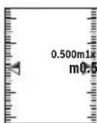
Note: The measured value typically appears within 0.5 s and no later than approx. 4 s. The duration of the measurement depends on the distance, the lighting conditions and the reflective properties of the target surface. Upon completion of the measurement the laser beam is automatically switched off.
Selecting the Reference Level (see figure A)
For the measurement, you can select between three different reference planes:
- the rear measuring-tool edge (e.g. when measuring onward from a wall),
- the front measuring-tool edge (e.g. when measuring onward from a table edge),
- the centre of thread 13 (e.g. for tripod measurements).


English | 35

To select the reference level, press button 4. Use button 3 [+] or button 8 [-] or button 4 to select the desired reference level. The rear edge of the measuring tool is preset as the reference level every time the measuring tool is switched on.
"Basic Settings"
To enter the "basic configurations" menu (i) press and hold the button 7 [Func].
Select the respective basic configuration and your setting.
To exit the "basic configurations" menu, press the On/Off button 5 [ 心 ] again.
Display Illumination
The display illumination is continuously switched on. When no button is pressed, the display illumination is dimmed after approx. 20 seconds to preserve the batteries/rechargeable batteries.
Measuring Functions
Length Measurement
Select the length measurement
To switch on the laser beam, briefly press the measuring button 2 [▲].
To measure, briefly press the measuring button 2 [▲]. The measured value will be shown at the bottom of the display.
Continuous Measurement (Tracking)
For continuous measurements, the measuring tool can be moved relative to the target, whereby the measuring value is updated approx. every 0.5 seconds. In this manner, as an example, you can move a certain distance away from a wall, while the actual distance can always be read.
Select the continuous measurement
To switch on the laser beam, briefly press the measuring button 2 [▲].
Move the measuring tool until the required distance value is indicated in the bottom of the display.


Bosch Power Tools 1609 92A 1RR| (26.11.15)


36 | English
Briefly pressing the measuring button 2 [▲], interrupts the continuous measurement. The current measured value will be shown at the bottom of the display. The maximum and minimum measured value appear above it. Pressing the measuring button 2 [▲] once more, restarts the continuous measurement.
Continuous measurement automatically switches off after 5 mins.
Area Measurement
Select the area measurement
Then measure the width and length one after the other as with a length measurement. The laser beam remains switched on between the two measurements. The distance to be measured flashes in the indicator for area measurement
The first measured value is shown at the top of the display. After the second measurement has been completed, the area will be automatically calculated and displayed. The end result is shown at the bottom of the display, while the individual measured values are shown above it.
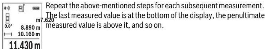
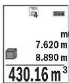
Volume Measurement
Select the volume measurement
Then measure the width, length and depth one after the other as with a length measurement. The laser beam remains switched on between the three measurements. The distance to be measured flashes in the indicator for volume measurement
The first measured value is shown at the top of the display. After the third measurement has been completed, the volume will be automatically calculated and displayed. The end result is shown at the bottom of the display, while the individual measured values are shown above it.
Indirect Distance Measurement
For indirect length measurements, three measuring modes are available. Each measuring mode can be used for determining different distances.
The indirect distance measurement is used to measure distances that cannot be measured directly because an obstacle would obstruct the laser beam or no target surface is available as a reflector. This measuring procedure can only be used in vertical direction. Any deviation in horizontal direction leads to measuring errors.
Note: Indirect distance measurement is always less accurate than direct distance measurement. Depending on application, greater measuring errors are possible than


English | 37
with direct distance measurement. To improve the measuring accuracy, we recommend using a tripod (accessory).
The laser beam remains switched on between the individual measurements.
a) Indirect height measurement (see figure B)
Select the indirect height measurement
Ensure that the measuring tool is at the same height as the lower measuring point. Then tilt the measuring tool around the reference level and measure the distance "1" as for a length measurement (displayed as a red line).
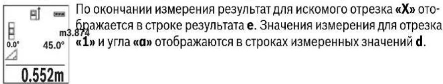
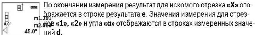
Upon completion of the measurement, the result for the sought distance "X" is displayed in the result line e. The measuring values for the distance "1" and the angle "a" are displayed in the measured-value lines d.
b) Double indirect height measurement (see figure C)
The measuring tool can indirectly measure all distances, which lie in the vertical level of the measuring tool.
Select the double indirect height measurement
Measure distances "1" and "2" in this sequence as for a length measurement.
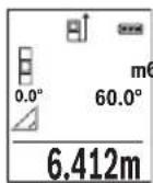
Upon completion of the measurement, the result for the sought distance “X” is displayed in the result line e. The measuring values for the distances “1”, “2” and the angle “a” are displayed in the measured value lines d.
Pay attention that the reference plane of the measurement (e.g. the rear edge of the measuring tool) remains exactly at the same location for all individual measurements within a measuring sequence.
c) Indirect length measurement (see figure D)
Select the indirect length measurement
Pay attention that the measuring tool is positioned at the same height as the sought measuring point. Now, tilt the measuring tool around the reference plane and measure distance "1" as for a length measurement.
Upon completion of the measurement, the result for the sought distance "X" is displayed in the result line e. The measuring values for the distance "1" and the angle "a" are displayed in the measured-value lines d.
Bosch Power Tools 1609 92A 1RR| (26.11.15)


38 | English
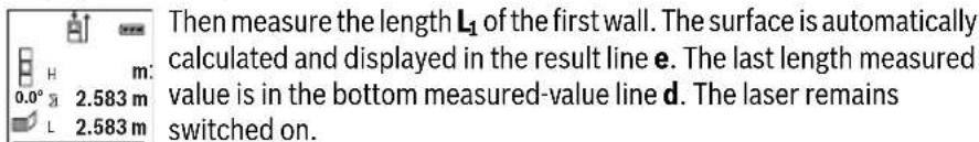
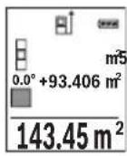
Wall Surface Measurement (see figure E)
The wall surface measurement is used to determine the sum of several individual surfaces with a common height.
In the illustrated example, the total area of several walls should be determined, which have the same ceiling height H , but different lengths L .
Select the wall surface measurement
Measure the ceiling height H as with a length measurement. The measured value is displayed in the top measured-value line. The laser remains switched on.
3.336 m²
Now measure the length L_2 of the second wall. The individual measured value displayed in the measured-value line d is added to the length L_1 .
The sum of the two lengths (displayed in the middle measured-value line d) is multiplied by the saved height H. The total surface value is displayed in the result line e.
You can measure any number of lengths L_x which will be automatically added and multiplied by the height H.
The requirement for a correct area calculation is that the first measured length (for example the ceiling height H ) is identical for all sub-areas.
Stake out function (see figure F)
The stake out function repeatedly measures a defined length (distance). These lengths can be transferred to a surface, for example to enable material to be cut into pieces of equal lengths or to install stud walls in a drywall construction. The minimum adjustable length is 0.1m , the maximum adjustable length is 50m .
Select the stake out function.
Set the desired length. Using button 7 [Func] select the corresponding digit/position and change the value with button 3 [+ or button 8 [-] .
Begin the stake out function by pressing the measuring button 2 [▲] and slowly move away from the starting point.
The measuring tool continuously measures the distance to the starting point. The defined length and the current measured value are thereby displayed. The lower or upper arrow displays the shortest distance to the next or last marking.
Note: The continuous measuring enables you to set a measured value as a defined length by pressing the button 4.


English | 39
The left factor specifies how many times the defined length has already been reached. The green arrows on either side of the display indicate the reaching of a length for marking purposes.
Inclination Measurement/Digital Spirit Level
Select the inclination measurement/digital spirit level
The measuring tool automatically switches between two states.
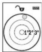
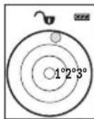
The digital spirit level is used to check the horizontal or vertical alignment of an object (e.g. washing machine, refrigerator, etc.). When the inclination 3^ exceeds, the ball in the display lights red.
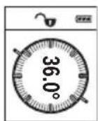
Inclination measurement is used to measure a slope or incline (e.g. of stairs, railings, when fitting furniture, laying pipes, etc.). The left-hand side of the measuring tool serves as the reference level for grade measurement. If the display flashes during measurement, the measuring tool has been tipped too heavily to the side.
Memory Functions
The value or end result of each completed measurement is automatically saved.
Memory value display
Maximum 30 values (measured values or end results) can be retrieved.
Select the memory function
The number of the memory value is shown at the top of the display, the corresponding memory value is shown at the bottom and the corresponding measuring function is shown on the left. Press button 3 ([+] to browse forwards through the saved values. Press button 8 ([-]) to browse backwards through the saved values.
If there is no value available in the memory, "0.000" is shown at the bottom of the display and "0" at the top.
The oldest value is located in position 1 in the memory, while the newest value is in position 30 (when 30 memory values are available). When a further value is saved, the oldest value in the memory is always deleted.

Bosch Power Tools 1609 92A 1RR| (26.11.15)


40 | English
Deleting the Memory
To delete the content of the memory, press button 7 [Func] and select the memory function. Then briefly press the On/Off button 5 [c] to delete the displayed value.
Simultaneously pressing the button 4 and the On/Off button 5 [ 心 ] deletes all values stored in the memory.
Adding/Subtracting Values
Measured values or end results can be added or subtracted.
Adding Values
The following example describes the addition of areas:
Measure an area as described in section "Area Measurement", see page 36.
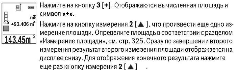
Press the button 3 [+] . The calculated area and the symbol “+” will be displayed.
Press the measuring button 2 [▲] to start another area measurement. Measure the area as described in section "Area Measurement", see page 36. Once the second measurement is completed, the result of the second area measurement is displayed below. To show the end result, press the measurement button 2 [▲] once more.
Note: With a length measurement, the end result is displayed immediately.
To exit addition, press button 7 [Func].
Subtracting Values
To subtract values, press button 8 [-]. The subsequent steps are the same as for "Adding Values".
Deleting Measured Values
Briefly pressing the On/Off button 5 [ ] will delete the last measured value in all measuring functions. Repeated brief pressing of the On/Off button 5 [ ] will delete the measured values in reverse order.
Changing the Unit of Measure
Unit of measure "m" (metres) is set by default.
Switch the measuring tool on.
Press and hold button 7 [Func], to enter the "basic configurations" menu. Select "ft/m".
Press button 3 [+ or button 8 [-] , to change the unit of measure.
Press the On/Off button 5 [ ] to exit the menu item. The selected setting remains saved after you switch off the measuring tool.


English | 41
Bluetooth® Interface
Data Transmission to other Devices
The measuring tool is equipped with a Bluetooth® module, which enables data transmission via radio technology to certain mobile terminals/devices with a Bluetooth® interface (e.g., smartphones, tablets).
For information on the necessary system requirements for a Bluetooth® connection, please refer to the Bosch website at www.bosch-pt.de.
For more information, visit the Bosch product page, see QR code, page 8.
For data transmission via Bluetooth®, time delays between mobile terminal/device and measuring tool may occur. This can be possible due to the distance between both devices or the object being measured.
Activating the Bluetooth® Interface for Data Transmission to a Mobile Terminal/ Device
To activate the Bluetooth® interface, press the Bluetooth® button 6 on the measuring tool. To activate the Bluetooth® signal, press the Bluetooth® button 6 or the button 3 [+] once again. Ensure that the Bluetooth® interface is activated on your mobile terminal/device.
To expand the functionality of the mobile terminal/device and to simplify the data processing, special Bosch applications (apps) are available. These can be downloaded in the respective stores, depending on the terminal/device.
The connection between mobile terminal/device and measuring tool is established after the Bosch application has started. If multiple active measuring tools are found, select the appropriate measuring tool using the serial number.
The connection status as well as the active connection (a) are displayed in the status bar (h) of the measuring tool.
Deactivating the Bluetooth® Interface
To deactivate the Bluetooth® connection, press the Bluetooth® button 6. To deactivate the Bluetooth® signal, press the Bluetooth® button 6 once again or the button 8 [-] or switch off the measuring tool.
Working Advice
For more information, visit the Bosch product page, see QR code, page 8.
The measuring tool is equipped with a radio interface. Local operating restrictions, e.g. in airplanes or hospitals, are to be observed.

English | 43
Accuracy Check of the Distance Measurement
The accuracy of the measuring tool can be checked as follows:
- Select a permanently unchangeable measuring section with a length of approx. 3 to 10 metres; its length must be precisely known (e.g. the width of a room or a door opening). The measurement should be carried out under favourable conditions, meaning, the measuring distance must be indoors and the target surface for the measurement must be smooth and reflect well.
-Measure the distance 10 times after another.
The deviation of the individual measurements from the average value must not exceed ± 4mm over the entire measuring section in favourable conditions. Record the measurements in order to be able to compare the accuracy at a later date.
Working with the Tripod (Accessory)
The use of a tripod is particularly necessary for larger distances. Position the measuring tool with the 1/4 thread 13 onto the quick-change plate of the tripod 19 or a commercially available camera tripod. Tighten the measuring tool with the locking screw of the quick-change plate.
Set the corresponding reference level for measurement with a tripod by pushing button 4 (the reference level is the thread).
Error Message
If a measurement cannot be performed correctly, the error message "Error" appears in the display. Switch the measuring tool off and back on, and start the measurement again.

The measuring tool monitors correct functioning in every measurement. If a defect is detected, the display will indicate only the symbol shown opposite and the measuring tool switches itself off. In this case, have the measuring tool checked by an after-sales service agent for Bosch power tools.
Maintenance and Service
Maintenance and Cleaning
Keep the measuring tool clean at all times.
Do not immerse the measuring tool in water or other fluids.
Wipe off debris using a moist and soft cloth. Do not use any cleaning agents or solvents.
Bosch Power Tools 1609 92A 1RR| (26.11.15)


44 | English
Maintain the reception lens 14 in particular, with the same care as required for eye glasses or the lens of a camera.
In case of repairs, send in the measuring tool packed in its protective pouch 16.
After-sales Service and Application Service
Our after-sales service responds to your questions concerning maintenance and repair of your product as well as spare parts. Exploded views and information on spare parts can also be found under:
www.bosch-pt.com
Bosch's application service team will gladly answer questions concerning our products and their accessories.
In all correspondence and spare parts orders, please always include the 10-digit article number given on the nameplate of the product.
Great Britain
Robert Bosch Ltd. (B.S.C.)
P.O.Box 98
Broadwater Park
North Orbital Road
Denham
Uxbridge
UB95HJ
At www.bosch-pt.co.uk you can order spare parts or arrange the collection of a product in need of servicing or repair.
Tel. Service: (0344) 7360109
E-Mail: boschservicecentre@bosch.com
Ireland
Origo Ltd.
Unit 23 Magna Drive
Magna Business Park
City West
Dublin 24
Tel. Service: (01) 4666700
Fax: (01) 4666888


François
Français
Laser Radiation Do not stare into beam Class 2 laser product
Executive Vice President
Head of Product Certification
Engineering
PT/ETM9

S APQ = S AQC + S_ PPD
Robert Bosch GmbH, Power Tools Division
70764 Leinfelden-Echterdingen, GERMANY
Leinfelden, 10.11.2015
Laser Radiation Do not stare into beam Class 2 laser product
Executive Vice President
Head of Product Certification
Engineering
PT/ETM9

S APQ = S AQC + S_ PPD
Robert Bosch GmbH, Power Tools Division
70764 Leinfelden-Echterdingen, GERMANY
Leinfelden, 10.11.2015
Executive Vice President
Head of Product Certification
Engineering
PT/ETM9

j_u B i.v. h = w
Robert Bosch GmbH, Power Tools Division 70764 Leinfelden-Echterdingen, GERMANY Leinfelden, 10.11.2015
Do not stare into beam
Class 2 laser product


Italiano | 105
Executive Vice President
Head of Product Certification
Engineering
PT/ETM9


Robert Bosch GmbH, Power Tools Division
70764 Leinfelden-Echterdingen, GERMANY
Leinfelden, 10.11.2015
Componenti illustrati
Do not stare into beam
Class 2 laser product
Executive Vice President
Head of Product Certification
Engineering
PT/ETM9

f^ ( x) = - ( 2x + 1) ( ax - 1) x = 0
Robert Bosch GmbH, Power Tools Division
70764 Leinfelden-Echterdingen, GERMANY
Leinfelden, 10.11.2015
Kies de lengthemeting
Do not stare into beam
Class 2 laser product
Executive Vice President
Head of Product Certification
Engineering
PT/ETM9

knTd = 12
i. v.k = w _____
Robert Bosch GmbH, Power Tools Division
70764 Leinfelden-Echterdingen, GERMANY
Leinfelden, 10.11.2015


1609 92A 1RR| (26.11.15) Bosch Power Tools


Dansk | 145
Deaktivering at Bluetooth®-interface
Executive Vice President
Head of Product Certification
Engineering
PT/ETM9

f_( 2) = h · m
Robert Bosch GmbH, Power Tools Division
70764 Leinfelden-Echterdingen, GERMANY
Leinfelden, 10.11.2015
Illustrerade komponente
Bosch Service Center
Telegrafvej 3
2750 Ballerup
Danmark
Tel.: (08) 7501820 (inom Sverige)
Fax: (011) 187691
Avfallshantering
Laser Radiation Do not stare into beam Class 2 laser product
Hvis teksten på adverselskiltet ikke er på dittspråk, på lime en etikett på dittspråk over dette skiltet før du tarproduktet i bruk.

Rett aldri laserstrålen mot personer eller dyr, og se ikke selv rettinn i den direkte eller reflekterte laserstrålen.Det kan fere til blending,uhell ogøyeskader.
Ved oyekontakt med laserstralen ma oyet lukkes bevisst og hodet straks beveges bort fra stralen.
Det mä ikke gjores endringer på laserutstyret.
▶ Bruk laserbrillene aldris som beskyttesesbriller. Laserbrillene er til bedre regist- trering av laserstralen, men de beskytter ikke mot laserstrålingen.
Bruk laserbrillene aldri som solbriller erler i trafikken. Laserbrillene gir ingen fullstendig UV-beskyttelse og reduserer fargereigristeringen.


Norsk|175
Executive Vice President Engineering
Head of Product Certification PT/ETM9

Robert Bosch GmbH, Power Tools Division 70764 Leinfelden-Echterdingen, GERMANY Leinfelden, 10.11.2015


Bosch Power Tools 1609 92A 1RR| (26.11.15)


178|Norsk
Illustrertekomponenter
Laser Radiation Do not stare into beam Class 2 laser product
OBJ_BUCH-2450-004.book Page 194 Thursday, November 26, 2015 10:46 AM


194 | Suomi
Henk Becker Helmut Heinzelmann
Executive Vice President Head of Product Certification
Engineering PT/ETM9

Robert Bosch GmbH, Power Tools Division 70764 Leinfelden-Echterdingen, GERMANY Leinfelden, 10.11.2015
Kuvassa olevat osat
Laser Radiation Do not stare into beam Class 2 laser product
'Otau to keiievo tnc npoeiobonountkic mivakidae dev eiva otyn yawooa tnc xwpaac aac, toe, npiv ntv npotn the an oe leitoupyia, koanote enavw tou nnu autokoannmivakiota nnyawooa tnc xwpac oac nou nepiexetai otn ouokeuaia.
Mny kateuovte Tny aktiva lecep enaw oe npoowna n zwa kai mny koitaleo i idoi kateuoeiav onv apeon h avakawevn aktiva letcp. Etai npopei va tupawote atopa,va npokaloeet atuxmuata na blambdae ta maiaac.
OBJ_BUCH-2450-004.book Page 211 Thursday, November 26, 2015 10:46 AM


EAAynikda 211
Texvika eyypapa otn:
Robert Bosch GmbH, PT/ETM9,
70764 Leinfelden-Echterdingen, GERMANY
Henk Becker
Helmut Heinzelmann
Executive Vice President
Head of Product Certification
Engineering
PT/ETM9

S APQ = S AQC + S_ PPD
Robert Bosch GmbH, Power Tools Division
70764 Leinfelden-Echterdingen, GERMANY
Leinfelden, 10.11.2015
Tata tata to 4 kai to nKto On-Off 5 [ ] diaypovotai oae ot Tneou piokovta otn vnhn.
Poo0eon/apaipoeon rupov
Oi tuec eptponoc n ta teia k a anoteleogua ta unopei va npooteoov n va aapieoov.
PpOo0eON npov
To aokouo napadeiyua nepiypapcei tv npooeon enipaveiwv:
Ynooyotemu enipaveia oupwaue nveovotna «Metponenepipaveivv》,Bene otne 0e1a 215.
PiTnote to nIjkpo 3 [+] . Eupavizetai n unoloyioevn enipaveia kai to aUBoAo (一 + 一) PiTnote to nIjkpo mepponc 2 [A], yia va fekivnoeTe mia nepaitep w ptonon emipaveiaac. Ynoayoiote tvv enipaveia oupwva me tvv evotnta Mepponen eipaveiwv, Bane otn aeAida 215. Moic oloknpwei n deutepn metpon, eupavizetai to anotetaleoqa tnc deutepnc metponc enipaveiaac katw otnv oovn. Tia tvn npoBn tou teAikou anoteleopaaTOC, PnTnote ek vevou to nIjkpo mepponc 2 [A]
Yno6eIg: e nepiwnn mac metponnc uKouc eapaviieta aoeoc to teAiko anotelae
Tia nvykaraalewn tnc npoaeon nathote ton ktpo 7 [Func].
Apaipoeon tyow
Tia Tnv apaipeoan Tmuov nathote To nAHTPO 8 [-]. H nepaIepw diadikaoia eival avdoyn pe Tn diadikaoia «Pioo0eon Tmuov
Ataypaip npov metponc
Pataovtac ouvtota o ankto Po On-Off 5 [c], unopeite va o bhoote oe oae tic aeitoupyie metponnc tnv teueutaia unoloyiaevn tih metponnc. Pataovtac enaveianmueva ouvtota to ankto Po On-Off 5 [c], diaypaoovtai oi tipe c metponnc me tvn avtietn oeipa.
Alambda'ovadac metpnonc
Suvtnpnon kal Service
Suvtnpnon kai kaapiooc
Na diatnpieTe to epyaIeio tepnong navTa ka@apó.
Mn u i e to epyaleio metpnonc ovepo n ae aa uypa.
Kaθapiετe tuxov pounouc kai βρωμiεc μ'eva uypó, paλakó navi. Mn xŋoiponoiéte μεσa kaθapioμouh δiaλuteç.
Na nepinoiote idaiertepa to paako hync 14 me tny iia npooektikotnta nou nepinoite ta yuaia oac kalh tn foovapikn oc unxavn.
To epyaieio mepnoic npenei va anooteaaeai ia eniokeun poea otny npootateutikn Toavta 16.
Service ka npoxn ouuouxphoc
To Service anavt oic epothoeic oac oxetikae tyn etiokeun kal tn ouvtipnon tou npioovoc oac kaohyc ia ta katalaa avtalakntikda:
www.bosch-pt.com
Houda npoxnC ouBouawv Tnc Bosch anavra euxapiotoc otic epwntnoec oac oxetik ape Ta npoiovta paac kai ta avtaaaktikauc.
Aωe OE oλε TC epwthoeic kai npayyeAiec avtaaakTKov OTwoBnTote TO 10ηΦIO KωδiKO apθμo ouφwva μe TnV nivaikda tunou Tou poiovtoc.
EAAaδa
Robert Bosch A.E.
Epxeiac 37
19400Kopmi-Aθηγα
Tnλ.: 2105701258
Φaξ:2105701283
www.bosch.com
www.bosch-pt.gr
ABZ Service A.E.
Tnλ:2105701380
Φaξ:2105701607
Türkçé | 225
Anoupon
Ta epyaieia meptnonc, Ta eapntmuata kal oouakeuaoeic npenti va avakukawovtal me tpoio piko npoc to nepiaalov.
Mny piete Ta epyaleia petnnc kal n pcnatapie ota anoppmuata tou ontiouac!
Móvo yia xópec tnc EE:
Do not stare into beam
Class 2 laser product

226|Türkse
Bataryalar 2x1,5VLR03(AAA)
Akü hücreleri
2× 1,2V HR03 (AAA)
Batarya kullanim omru, yak.
-Tekilolcuminer
-Surekliolcum
Henk Becker Helmut Heinzelmann
Executive Vice President Head of Product Certification
Engineering PT/ETM9
j_u B i.v. u = u
Robert Bosch GmbH, Power Tools Division 70764 Leinfelden-Echterdingen, GERMANY Leinfelden, 10.11.2015
OBJ_BUCH-2450-004.book Page 243 Thursday, November 26, 2015 10:46 AM


Türkce|243
Gunday Otomotiv
Beylikduzü Sanayi Sit. No: 210 Beylikduzü
istanbul
Tel.: 02128720066
Aygem
10021 Sok. No: 11 AOSB Cigli
Izmir
Tel.: 0232 3768074
Sezmen Bobinaj
Ege Is Merkezi 1201/4 Sok. No: 4/B Yenisehir
izmir
Tel.: 02324571465
Ankarali Elektrik
Eski Sanayi Bolgesi 3. Cad. No:43
Kayseri
Tel.: 0352 3364216
Asal Bobinaj
Eski Sanayi Sitesi Barbaros Cad. No: 24
Samsun
Tel.: 0362 2289090
Ustundag Elektrikli Aletler
Nusretiye Mah. Boyacilar Araligi No: 9
Tekirdag
Tel.: 02826512884
Tasfiye
Laser Radiation Do not stare into beam Class 2 laser product
OBJ_BUCH-2450-004.book Page 248 Thursday, November 26, 2015 10:46 AM


248 | Polski
Executive Vice President
Head of Product Certification
Engineering
PT/ETM9

S APQ = S AQC + S_ PPD
Robert Bosch GmbH, Power Tools Division
70764 Leinfelden-Echterdingen, GERMANY
Leinfelden, 10.11.2015
Robert Bosch Sp. z o.o.
OBJ_BUCH-2450-004.book Page 266 Thursday, November 26, 2015 10:46 AM


266 | Cesky
Executive Vice President
Head of Product Certification
Engineering
PT/ETM9

k_n//x
i.v. h = m
Robert Bosch GmbH, Power Tools Division
70764 Leinfelden-Echterdingen, GERMANY
Leinfelden, 10.11.2015


1609 92A 1RR| (26.11.15) Bosch Power Tools


Cesky|267
Zobrazéné componenty
Bosch Service Center PT
K Vapence 1621/16
692 01 Mikulov
Na www.bosch-pt.cz si si muzete objednat opravu Vaseho stroje nebo nahradni dily online.
Tel.: 519305700
Fax: 519305705
E-Mail: servis.naradi@cz.bosch.com
www.bosch.cz

1609 92A 1RR| (26.11.15) Bosch Power Tools


Slovensky | 279
Zprcovani odpadu
Do not stare into beam
Class 2 laser product

Bosch Power Tools 1609 92A 1RR| (26.11.15)


280 | Slovensky
IP 54 (chranene proti prachu
astriekajucejfoode)
Bluetooth® 4.0 (Classic
a Low Energy)
A) Pri merani od zadnej hrany meracieho pristroja plati pre velmi dobré reflxné vlastnosti ciel'a (napriklad napielo natretá stena) slabé osvetlenie v pozadi a prevádkovú teplotu 25 °C. Okrem to-ho je potrebné počitá vplyvom ± 0,05 mm/m.
B) Pri merani od zadnej hrany meracieho pristroja, plati pre vysoke reflexné vlastnosti ciefa (napr. biely kartón), silné osvetlenie v pozadi a prevadzkovú teplotu - 10 °C až + 45 °C. Okrem toho je potrebné počitāt sodchylkou ±0,15 mm/m.
C) Po kalibracii pri 0^ a 90^ pri dodatochney chybe stupania maximalne ± 0,01^ /stupnov do 45^
D) Pri prevadzkovej teplate 25°C
E) Vo funkci Trvalé meranie je maximalna prevádková teplota +40°C.
F)s vynimkou priehradky na baterie
G) Pri použiti pristrojov Bluetooth®-Low-Energy moze byt podla modelu a prevalzkové systému moźne, ze sa nevytrovi spojenie. Pristroje Bluetooth® musia podporovat SPP profil.
H) Bluetooth® deaktivovany
I) Ako základná rovina pre meranie sklonu slúží l'avá strana meracieho prístroja.
Na Jednoznacnú identifikaciu Vásho meraceho pristroja slúzi sérióve cislo 11 na typovom stitku.


Slovensky | 283
Vyhlasenie o konformite C
Vyhelasujeme na vyhradnú zodpovednost, ze vyrobok opisaný v Časti „Technické udaje“ spína vsetky prislušné ustanovenia smernic 1999/5/ES a 2011/65/EU vrátane ichzmien a je v sulade s nasledujúcimi normami: EN 61010-1: 2010-10, EN 60825-1: 2014-08, EN 300 328 V1.8.1: 2012-06, EN 301 489-1 V1.8.1: 2008-04, EN 301 489-1 V1.9.2: 2011-09, EN 301 489-17 V2.2.1: 2012-09, EN 62479: 2010-09, EN 50581: 2012.
Technické podklady má spolocnost: Robert Bosch GmbH, PT/ETM9, 70764 Leinfelden-Echterdingen, GERMANY
Henk Becker Helmut Heinzelmann
Executive Vice President Head of Product Certification
Engineering PT/ETM9

Robert Bosch GmbH, Power Tools Division 70764 Leinfelden-Echterdingen, GERMANY Leinfelden, 10.11.2015
Vyobrazene componenty
Laser Radiation Do not stare into beam Class 2 laser product
Executive Vice President
Head of Product Certification
Engineering
PT/ETM9

w_0 Q
i. v.k = w _____
Robert Bosch GmbH, Power Tools Division
70764 Leinfelden-Echterdingen, GERMANY
Leinfelden, 10.11.2015
1609 92A 1RR| (26.11.15) Bosch Power Tools


Magyar | 301
Laser Radiation Do not stare into beam Class 2 laser product
EcnTekCT npedynpeHbHO Tabnukn He Ha a3bke Baewc TpaHbI, 3aKneTe ero neped nepBOk KcNpyatauee npnaeraMoH haknekoHa 3bKe Baewc cTpaHbI.

He HanpaBnIte lyu na3epa Ha IIOeH HIN XHBOTbIX H Camn He CMOtPnte Ha npAmoH HIN OTPpaxaEmbH Lyu na3epa. 3TOT nyu MOKeT CIneINTb IIOeH, CTaTb IIpNHHoH HeCuaCTHO TcIyAra HIN IOBpeNTb Fna3a.
B cnyuae nonaahanna3ephoro nyu a rna3 rna3a hyxho HamepeHHO 3aKpbItb HemeJeHNO OTBepHyTbcr O Tnya.
He meHnTe Hnuero B naeepHom ycTpoNCTBe.
He npmeHne na3epHbIe ouKn B KaueCTBe 3aunTHbIX OOKOB. Na3epHbIe ouKn cnJxat dIyIyUWeI paCnO3HaBaHIn Ia3epHoro lyuA, Ondako OHn He 3aunuaOT Na3epHoro n3nyeHn.


Pycckn | 317
He npmeHnTe na3epHbIe ouKn B KaueCTBe conHehBix ouKOB HnB yHnHOM DBHXeHH. Na3epHbIe ouKn He daIoT nonHo 3aunHbI OTyIbTpapnoJeTOBOrO n3nyehn H yxudaiOT BocnpnTne Kpacok.
Pemont BaWero n3MepHTeNbHOro HHCTpymeHaTo npuyaTe TOnbKO KBaHnHnHpOBaHHOMy nepcoHany, HcNoNb3yra TOnbKO opHrMaHbHbIe 3anaCHbIe qACTH. 3TNm oecneuHBaETc8e3OanacHOctb n3MepeTbe HrHO H-CTpyMeHTa.
He pa3pewaIte DeTm NOnb3OBAbCra Na3epHbIM H3MePHTeBbIM HHCTpyMentom 6e3 Ha30pa. OHMOrTy HeyMbIeHHO OcJIeNITb IIOJe.
He pa6oTaIe C mepHTeBhIM HnCTpyMeHToM BO B3pbIBOONaCHOcpe, no6n30CTn OT rOpUHX KndKoCTe, ra3OB nblnn. B n3mepHTeBHom HnCTpyMeHTe MOrY 06pa3OBaTbCra NCKpbl, OT KOTOpbIX MOXET BOCnIaMeHHTbcra Nbln npbl.
Octopoxho! Pn HcnoB30aHH N3MepTeHbHO HHCTpymeHTa C Bluetooth® BO3MOxHbI NOMEX dIpyrHX np6OpOB n yCTaHOBOK, cAmoneTOB n MeiunHcknx annapaTOB (HaNP., KApDIOCTHMyIaTOPOB, cLyXOBbIX annapaTOB). Kpome TOrO, HeIb3I ONHOCTbIO HCKNIOUHTb HAHeCEHne BpeDa HaXoJIMcB HENOCpeCTBEHNHO 6bn3OCTn IIOdAM n XHBOTbIM. He NOnb3YInTECb H3MEpHTeBbHM INHCTpymeHTOM C Bluetooth® B6n3Hm MeINCHckNX annapaTOB, 3anpaBOuHbIX CTAHzMI, XHMueCKNX YCTAOBOK n TeppHTOPHI, Ha KOTobix cyuectByet OnaCHOCTb B3pbIBa HNN MOrYT pNOBoITbCBA3pbIBHbI pa6OtBI. He NOnb3yInTECb H3MEpTeBbHM INHCTpymeHTOM C Bluetooth® B camonetax. CtapaiTecb He BKNIOUaTB erO Ha npOdoJXHTeNbHOE B HenocpeCTBeHNHO 6bn3OCTn OT Ta.
CnoBechI ToprobH 3nak Bluetooth® n rpaΦnueckn 3nak (norottn) ABnIOTc 3aperncTpnpoBaHHbIM TOBapHBIM 3nAKOM N co6ctBeHHocTbIO Bluetooth SIG, Inc. KomnaHra Robert Bosch GmbH Hcnonb3yET 3TOT CnoBecHbIM TOBapHbIM 3nak/norottn no nHceH3nn.
Oncsahanne npodukta n ycnyr
Ioxayncta,OTKpoTe packlaHyIO CTpaHnCy C NIIIOCTpaunMn HNCTpyMeHTA nOCTaBnTe ee OTKpbITOn, NOKa Bbl3yuaTe pykoBOdCTBO NO 3Kcnnyatau.
PnmeHne no Ha3haueHmIO
H3MepntbHbHnHCTpymeHT npedHa3NaueH dIy H3MpeHnPaCToHH, DnH, BblcoT, ydaJIeHn IyKIOHOB n paCuTe Ta IIOUaJe N O6bEMOB.
Pe3ynbTaBtI 3MepeHnMoXHO nepeDaTb uepe3 Bluetooth® HaДугп epn60pbI.
Bosch Power Tools 1609 92A 1RR| (26.11.15)


318|Pycckn
TexHnueckne daHHbIe
Executive Vice President
Head of Product Certification
Engineering
PT/ETM9

j_u B( 0) . i.v. h · m
Robert Bosch GmbH, Power Tools Division 70764 Leinfelden-Echterdingen, GERMANY Leinfelden, 10.11.2015
H306paXeHHbIe COCTaBbIe qactn
HymepaunipnepctabneHHbixcoCTaHBbIXacTeB BInIOJIHeHaNoI3o6paKeHHIO 13MepeTbHOrHO IHCTpyMeHTa Ha cTpaHnue C NIIIOCTpaJnMn.
1Диспnett
2 KhoNka H3MepeHnra[ ]
3 KhoNka «ПИС» [+]
4 KhoNka BbIbopa nIOCKOCTHOCTeTa
5 BbIKNIOuATenb [
6 KhoNka Bluetooth®
7 Khonka pekma [Func]
8 KhoNka «MHHyc»[-]
9 Kpbiika 6aTaapeHoro oTceka
10ФнкcatopКрblшкбат胺иHoroOTceka
11 CepnHbI Homep
12 PpeynpeTbnha Ta6nka na3epHoro n3nyehna


Pycckn321
13 Pe3b6oBoe OTBepCTne IaTnBa 1/4"
14PnEHHaJIHH3a
15 BbIXoI na3epHoro lyuA
16 3aunTHbIyueXoI
17 BnHpaMapka
18 Oukn dna pa6oTbI cna3epHbIM HHTpyMeHToM
19 LiTaNtB
*H3o6paXeHHbI HIN ONcaHHbI pNHaIeXHOCTH He BXOaT B CtaHdapTHbI KOMnneKT NOCTaBKn.
HdNKaTopb1 (Bbl6op)
a Ctauyc Bluetooth®

Bluetooth® aKTHBnPoBaH, CBa3b He yCTaHOBJeHa

Bluetooth® aKTHBnPoBaH, CB83b yCTaHOBneHa
b PnOcKoCTb OTCuTea pHn H3MepeHHN
C INHdkaTop 3apJKeHHoCTn AKKyMylTOpHOB 6aTaPeN
d N3mepeHHbte 3NaueHn
e PeaynbTaT
F PeKHMbln3MepeHHN
g INHdkaTop yrnaHaKaNoHa
h Ctataych a CTpoka
i OCHOBHbIe HacTpoNKn
C6opka
YcTaHOBka/3aMeHa6aTapeek
B IN3MePHTeHbOM HnCTpyMeHTe peKoMeHnyeTc HcNoIb3OBA Tb IeNoUHO-MapraH-ueBbIe 6aTapeKn nnakKymyIaTOpHbIe 6aTapeN.
C aKKMyIaTOpHbIMn 6aTapeAIMn Ha 1,2 B BO3MOXHO MeHbIe N3MepeHm, yem C 6aTapeKAMn Ha 1,5 B.
UTo6bl OTKpbItb KpbIshky 6aTaapeHoro 0TeKeKa 9, HaxMMte fHKCaTOp 10 n CHMnTe KpbIshky 6aTaapeHoro 0TeKeKa. BcTabBe 6aTaapeKn nn AkkMyJrTOpHbe 6aTaapeN.
CneIte 3a npabnBHO NOIpaHOCbIO B COOTBeTCTBHN C N3o6paJxHeM Ha BVHTpeHHe CTOpOHe KpbIuK6bATapeHOrO OTeKa.


322|Pycckn
Pn nepbom noBHeHH nycTOrO cMbOla 6aTapeKn HaDnCnpee MOxHO BblOnHHTb eue np6n.100 n3MepenH.Ecnn CmBON 6aTapeKn yctToN Mnraet KpaChbIM, daJIbHeIne n3MepeHnE HbO3MOXHb.I.3aMeHnTe 6aTapeKn nnn aKKyMyJrTopHbIe 6bapen.
Bcerda 3aMeHnTe BCE 6aTapeKn/AKKymyIaTOpHbIe 6aTapeN OndHOBpeMeHHo. Ic- nOJIb3yIte TOLbKO 6aTapeKn/AKKymyIaTOpHbIe 6aTapeN OndHOrO npOn3BOIteJI N C OINHaKOBoE MKOCTbIO.
BbHMaTe 6aTapeKn/AKKymyIaTOPhIe 6aTapeH N3 H3MePHTelbHOrO HCTpyMeNTa,ecn Bbl dntenbHoe BpeM He 6ydeTe ero nCNoB30BaTb.Pnp DnHTeBHOM XpaHeHH BO3MOxHa Koppo3Ha Hn CaMopa3pIka 6aTapeek/AKKymyIaTOPhIX 6aTapei.
Pa6ota c nHcTpymeHTOM
3Kcnnnyataun
He octabnate 6e3 npncmOTpa BkHoueHHbI H3MePHTbHbI HNCTpyMeHT BBKIOUaTe erO nocne HCNoB3OBAHNApyrHe Iuca MoYr 6bITb ocIeJIeHbI Na3epHbIM Ny4OM.
3aunuatae H3MepntbHbI INHCTpyMeHT OT BnAHN pRMBIX CONHeuBix Nyuei.
He noDBepraTe n3MepnteBbHbIN HNCTpyMeHT BO3deIcTBHO 3KCTpeMaJIbHbIX TemnepaTy n TemnepaTyphbx nepenaIOB. B acTHocTH, He ocTaNrTe erO Ha dInTeBHOe BpemBaMaUNHe. Pn60nbux nepenadax TemnepaTypb CHaHaJaTaTe N3MepnteBbHOMy INCTpyMeHTy cTabuN3HPOBaT CBOIO TemnepaTypy, npexKe YEM NaHbPa6oTaTb C Hm. 3KCTpeMaJIbHbIe TemnepaTybl N TemnepaTyphble nepenadbl MOryt OTPuaTeBHO BlNArTb Ha ToUHOCTb N3MepnteBHo-TO HHCTpyMeHTa.
H36eraIte CNbHbIX TOUKOB H naDEHHN H3MePHTeBHO HOHCTpyMeHTa. IocIe CNbHbIX BHeUHIX BO3JeICTBn HA H3MePHTeBHyI NHCTpyMeHT peKOmeHdyETc npOBepNT bero TOUHOCTb, IpexJe yem IpOdoJkaTb pa60TaTb c INHCTpyMeHTOM (CM. «PpOBepKa ToUHOCTn H3MepeHHra pacCToHHra», CTp. 333).
BkIIOUeHne/BBIKIOUeHne
- YTO6bI BKNIOHTb H3MePHTeINbHbI INHCTpyMeHT n Ia3ep, KopoTko HaKMITEHa KHONKy H3MepeHn2 [▲].
YTO6bI BKNIOHTb H3MePHTeHbHbIN HHCTpyMeHT 6e3 Na3epa, KopoTKO HaKMITEHa BblKIIHOATeHb5 [ 心 ]


Pycckn323
He HanpaBnIte na3epHbI Iyu Ha IIOe Hnn XHBOTbIX H He CMOTpHTe camn Bna3epHbI IyU, B Tom uHcne n C 60nbWOrO pacCToHHN.
YTo6bI BbIKNIOHTb N3MePnteHbHbI INHCTpyMeHT, HaxMMTe N yDepKINBaTe HaKaTbIM BbIKNIOUaTeNb 5 [ ]
PnB BbIKIIOeHHN N3MepeHTeJIbHO INHCTpyMeHTa XpaHaIuNEcB NaMRTN 3HaueHn HAcTPOKN INHCTpyMeHTa COxpaHAIOTcR.
Ppoeypa n3MepeHHa
Iocne BkIOUeHnI3MePHTeBbHINHCpymeHT HxOaHTcB BpeXmE I3MepeHnI DnHbI.ДЯпepeKIOUeHnIBpyrOJpeXmI3MepeHnHaXMITE KHOKNy 7 [Func]. Bbl6epHTe Heo6xoHMbI peXm I3MepeHn KHOKNo 3 [+ ] INN KHOKNo8[-] (CM.«PeXmbl3MepeHn》,CTp.324).AKTHBnpyTe peXmI3MepeHn KHOKNo 7 [Func] INN KHOKNo I3MepeHn 2[▲].
IpepeBnraTe H3MePHTeNbHbIN HNCTpyMeHT Do TEX NOp, NOKa BHN3y INHCTpyMeHT He OTo6pa3NT Jxenaemoe pacCTOaHHe.


Pycckn325
KopoTKnH HkaTHeM Ha KhoNky 3MepeHn2 [▲] peXHM IpoJOnJKe TJIbHbIX N3MepeHn npepbIbaeTc. TekyUee H3MepeHHOe 3HaueHne OTo6paKaTaCBAHn3y Ha DCnPlee. MaKcMaJIbHOe MmHNMaJIbHOe H3MepeHHBe 3HaueHnOTo6paKaIOTCa HAD HNM. PpI NOBTOpHOM HaKaTHn Ha KhoNky 3MepeHn2 [▲] ONrTB BKNIOuAeTc npoJOnJKeTeHBoe H3MepeHne.
PexHM IpoDJIKNTeIbHbIX H3MepeHH aBtOMaTHueCKN OTKIOUaETcA uepe3 5MH.
H3mepenne nlooanda
Bb6epntepexHmH3MepeHHnIIOuaaN □
Iocne 3TOrO H3MepbTe No OuepeN uHpHy N dHny, KaK npu H3MepeHnX dHnHbI. MExdy oboHMn H3MepeHnMa3epHbI lyu ocTaeTCBKnUoyeHHbIM. H3MepeEmbI OTpe3OK Mmraet Ha HndkAtope H3MepeHnIIOaAn
19.355m2 蹲Boe H3MepenHoe 3NaueHne OTo6paXaetcB BBepy Ha DnCnIee. Pocne 3aBepseHnBTopoR H3MepenHn PIOuaDb paccuTbIbaeTc aBTOMaTHueckn H OTo6paXaETcK.KeHeHb pe3yIbTaT OTo6paXaETcBHN3y Ha DnCnIee,OTdEhBhie H3MepenHbE 3NaueHn -HaI HIM.
H3mepenHe 06bema
Bb6epntepekIMn3MepeHnaobbeMa
Iocne 3TOro H3MepeBTe No OuepeDen UHpy, DnHy n rny6hHy, Ka npn H3MepeHHn DnHbI. MexNy TpeMn H3MepeHHm Ia3epHbI Ny ocTaETcBKnHoueHHbIM. H3MepeEmbI OTpe3OK MHaet Ha HdNkatope H3MepeHHo obBeMa
IepBoe H3MpeHHOe 3HaueHne OTo6paKaaeTcB BBepy HaДиCnIee. m10.160 11.430m TpeTbeO H3MpeHn8 Obem aBTOMaTHueCKn paccuTbIBaETcN OTO6paKaetc. KoHehbl pe3yNbTaT OTo6paKaeTcB Hn3y HaДиCnIee,OTdJIbHbIe H3MpeHn8e 3HaueHn- HaD HIM. 1474.8m3
KocBeHHoe H3MepeHne pacCToHHN
IJI KOCBeHHoro H3MepeHn paCCToHn HmEeTc Tpu peKHMa H3MepeHn, C NOMO- 1bIO KOToPbIX MOxHO H3MeepTaB pa3NHyhle OTpe3KN.
KocBeHHoe H3MepeHne pacCToHnCnyKHTIIN H3MepeHn paCCToHn, KOtOpbHe HBO3MOxHO H3MePntb IprMbIM NyTeM, NockOJIbKy Ha TpaekTOpHn LyuA CyueCTByET npeTCTBHe HnH HeZeBoN IOBepXHocTH, CnyKaUeB KauEcTBe OTPaKaTeN. 3TO TcNoCo6 H3MepeHn MOKeT HcNOJb3OBaTbCra TOnbKO B BepTKaJIbHOM HanpaBHeHn. IIO-BoE OTKIOHeHne B RopH3OHTaBHom HapBaBHeHn BeDet K OUnbKaM B H3MepeHnx.
Bosch Power Tools 1609 92A 1RR| (26.11.15)


326 | Pycckn
Yka3aHHe: HnnpMoe n3MepeHne pacCToHnB BcEgdaTaMeHee ToHyb pe3yIbTaT ue m npMoe n3MepeHne pacCToHnB. TOrpeuHoCTn n3MepeHne MoYr 6bITb, yuHTbBA Bar cneunfky npmehn, 60nbHMn Yem npn npmom n3MepeHn pacCToHnR. Ipa NObIweHn TOHOCTn n3MepeHn Mbl peKOMeHdyem NcNoIb3ObaTb 7tATNB (pnpHaJIeXHOCTb).
B nepepbBe MeKdy OTdEnbHbIMn N3MepeHnMn Na3epHbI Lyu OcTaetcBKnIOueH HbIM.
a)KocbeHHoe H3MepeHHe BbICOTbl (cm.pnc.B)
Bb6epnte pekHM KOCBeHHORo 3MepeHnBaCtbl
CneIte 3a TeM, YTo6bI H3MpHTeBbI INHCTpyMeHT HaxOINcRa H OJHO BbICote C HIXKHe ToUKO H3MepEHn. 3aTeM HAKIOHNTe H3MpHTeBbI INHCTpyMeHT NO OTHOWeHHIO KIIIOCKOCTNOTcETa N H3MpBe OTpe3OK «1», KaK 3TO DeNaETCr PpH N3MepeHHn DInHbI (Ha IINcPlee PpeDctabNeH B VIne KpaCHOHnnn).
b)ДBOHHOE KOCBEHHOE H3MepeHne BBICOTbl (cM. pnc. C)
H3MepNTeBbHbHnHCTpyMeHT MoKET KOCBEHHo H3MepTb IIO6bIe pacCTOHHa,JeKa- 1ue B BeptNkAIBHO INOCKOCTn H3MepNTeBbHO IHCTpyMeHTa.
Bb6epntpeXIMDBOHORO KOCBEHHORO nMepeHnBaICOTbl
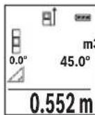
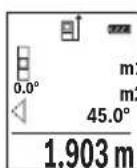
H3MepbTe, KaN npN H3MepeHHn DnIHbI, paCCToHnAe11111111111111111111111111111111111111111
1.903m CTeIe 3a TeM, UTo6bI BO BpeMa H3MepeHn IIOCKoCTb OTCuEta (Ha np., 3aHn KpaI H3MePHTeBHO rHcTpyMeHTa) HaxOdHnAcb PnB BCExEHNHcyBIX H3MepeHnx BO BpeMa Oepaun H3MepeHn CTpOro Ha ODHOM I TOM Xe MeCte.


Pycckn327
c) KocBeHHoe n3MepeHne nnHbI (cm. pnc. D)
Bb6epHTe peKIM KocBeHHOro N3MepeHnI nnHbl
CneIte 3a TeM, yTo6bl n3MpnteBHyb HnHCTpyMeHT HaxOdnnc Ha Toh JKe Bbcote, yTo n NCKOMaTouka n3MepenHa. HAKIOHHe 3aTeM n3MepntbHyb HnHCTpyMeHT IO OTHoHEHIO K PNOCKOCTn OTCuEta n H3MepbTe OTpe3OK «1», KaK 3TO DeJaETc npN H3-MepEHIN DInHbI.
IIO OKOHuaHHH N3MepeHHH pe3yNbTaT dIa HCKOMOrO OTe3Ka «X» OTOpaxKaetcB CToPKe pe3yNbTaTa e. 3HaueHHH N3MepeHHd IaOTpe3Ka «1» N yrta «a» OTo6paKaIoTcB C ToPOKaH N3MepeHHbIX 3HaueHH d.
H3MepeHne nnooaidn ctehbl (cm. pnc.E)
I3MepeHne IIOUaIcTeH NIOBONaET ONpeJeNITb O6uYIO IIOUaIb HeCKoJIbKnx cTeH, HMEIoUx ODNHaKOByIO BbICOTy.
B npBedeHHom npmepe Heo6xOIMO noIyntb 06uIIOaJb Heckonbkx CTcH COnHaKOBn BbICOTOn KOMHaTb H, HO c pa3NHyOH dINHOI L.
Bb6epTepeKHMn3MepeHnIIOuaaNCTeHbI
H3MepbTe BbICOTy KOMHaTbI H, KaK 3TO DeNaeTCr PnH3MepeHHN DInHbI. H3MepeHHoe 3HaueHHe OTo6paKaTcB B cepXne CTPOke. Na3ep ocTaetc BkIOueHHbIM.

3aTeM n3MepeBte dInHy L1 nepBoN cTeHbI. PnOuaJb paccuHTbIaETcABTOMaTHueckn H OTo6paXaetC B CTPOKe pe3yNbTaTa e. NocneJeHe n3MepeHHoe 3NaueHHe dInHbI yKa3bIbAeTCB HNXHe CTPOKe d. Na3ep OCTaETcB KJIIOUeHHbIM.
3.336m² Tepeb n3MepbTe dHnHy L2 BTOPOI cTHeI. YaKaaHHoe B CTOPEK n3MepeHHbIX 3HaueHn d eHNuHoe n3MepeHHoe 3HaueHne npnbAABJeTCK nIIHe L1. CyMa oBeHX dINH (OTo6paKaetcB CpeHne CTPOKe n3MepeHHbIX 3HaueHn d) yMHoxaETcRa HOxPAeHHyIO B pAmrN BBicOTy H. O6uee 3HaueHne IIOuAni OTo6paKaETcB CTOPE pe3yNbTaTa e.
Moxho n3mepntb eue IIO6e KOINueCTBO dnnH Lx, KOTOpbl eABTomaTHueckn CymnpyOTc H yMHoXaIOTc Ha BbICOTy H.
InpaBnHoro n3MepeHna Heo6xOIMO, Yo6bl n3MepeHHOe 3HaueHne nepBo nnHb (B npmepe - Bicota KOMHaTb H) 6blno NdeHTnHbIM dIra BCex OT- DeNbHbIX nIOaAed.


328|Pycckn
PexHM pa3MeTKn (cm.phc.F)
B pexnme pa3MeTKNoCToHHO OTMepaOTcOnpeDeeHHbI (pacctoHHa). 3TN dHbIMoXHO nepeHocHTb Ha NOBepxHOCTb, HAp.., nTPOTe3AHNOHNaKOBbIX OTe3KOB MaTePnHaA NIN DnMA MOHTnpoBaHHa Kapkaca IINCOKAPTOHHO o6uHBKn. HAcTpaNBAemAA MInHMaJIbHa dNHa CoCTaBnE T0,1 M, MaKcMaJIbHa dNHa coCTaBnE T50 M.
Bb6epnTepexKm pa3MeTK
3aJaTe JeNaeMyIOnHy.ДЯ 3TOK HonKo7 [Func] Bb6epHTe COOTBETCTByHOuO uΦpy/pa3pI Nn3MeHInTe 3HaueHne KONKo3 [+] nINn KONKo8 [-].
BkIOUHTpe pEXIM pa3MeTK, HaxaB Ha KHOKNy N3MepeHn2 [▲], n MeIeHNO ydaJIaHTecb OT HaayalbHOH TOOKN.
H3mepntenbHbHnHCTpymeHT HenpepbBHO H3mepaET pacCTOAHne DO hauanbHOTockn. Pn 3Tom OTO6paKaOTc yka3aHHbIe dINHBi N Teky- Uee H3mepehHOe 3HaueHne. BepxHra IIN HIXHRA CTpeNkA yka3bBAeT Ha HAnMeHbUee pacCToRHeNo Do cIeNyIOSe IIN ppoJNO OTMeTKn.
Yka3aHHe: Ecnpn HnpepbIBHom N3MepeHH HaKaTb KHOKky 4, MoXHo 3aDaTb N3MepeHHoe 3HaueHne B KaueCTBe yka3aHHoI dNInHb. Ko3oΦnIeHT cIeBa yka3bIaE, cKOBko pa36blNa DOCTnHyTa 3aHaHna dNInHa. 3eIeHbIe CTpeKN no 6OKam DnCnner yka3bIbaOT Ha DOCTNe KeHHe HxHOn dNInHbI dNl OTMeuaemOrO OTe3Ka.
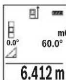
I3mepenHe yrna hakloHa/ZuΦpOBoB BaTePnAc
Bb6epTe H3MepeHne yrna HaKIOHa/ZufoPoBo BAtepnac
H3MepHTeIbHbI INCTpyMeHT aBTOMaTHueCKn NepeKJIouaETc MExkdy DByMa 3TMM peXmamn.
UHPOBOB BATEPnac CnyKNT DnI NPOBEPKN ROPN3OHTaNbHOCTN HIN BepTKaJIbHOCTN NOJIOKeHnO6BeKTA (HaNP., CTnpaJIbHOJ MaUNHbI, XONODINbHNKa NT.D.).
Pn npeBbIeHn HakoHa 3o WapNK Ha Incrnee ropnt KpaChbIM.
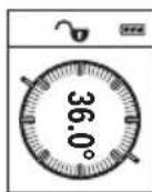
PexHM h3MepeHna HAKNoHa cnyKNT nIa H3MepeHna NIObema nn yKHOHa (HaNP., IeCTHNuHbIX npoTeOB, IeCTHNuHbIX pIoUaOk, pNn IOJrOHKe Me6eHH, npn PpOKNaKe Tpy6 nT. d.).
B KaueCTBe NIOCKOCTN OTCuETa BbICTyNAeT JeBaB CTOpOHa H3MepHTenbHOro IHCTpymEHTA.EcIN B IPOUecce H3MepeHHa MIRaET HnDKaTOP,TO H3MepHTeNBHy INHCTpymE TcNbHO HAKnOHeH B60K.
1609 92A 1RR| (26.11.15) Bosch Power Tools


Pycckn | 329
ФункшипamгтN
3NaueHHe Hn pe3yIbTaT KaKdOrO OTdIbHOrO N3MepeHHaCOxpaHReTCB NaMRTN aBTOMaTHueCKN.
OTo6paXeHne coXpaHeHHbIX 3HaueHn
IOCTyINHbIMAKcHMyM 30 3HaueHn (N3MepeHHbIX 3HaueHn INN KOHeuHbIX pe3yNbTaTOB).
Bb6epnte yHKnIO namrT
BbepyHa nCnnee oTo6paKaTcH OmepeKn NaMRTN, BHN3y COOTBeCTByIOUee coXpAHeHHoe 3HaueHne N CNeBa COOTBeTCTByIOUIM peKHM N3MepeHn.
430.16m³
HaKImaTe Ha KOnKy 3 [+] nIepeJIncTbIBaHn coXpaHeHHbIX 3Ha-ueHn BnepeI.
HaKMaTe Ha KhoNky 8 [-] npeHnctbBaHn coXpaHeHHbIX 3HaueHn Ha3aI.
EcnB namrHHe3HaueHn, Bn3y Haicnnee oTo6paKaetcR «0.000», a BBepxY - «O».
Camae cTapoe 3NaueHne haxoDITcB namrHn NOH omepOM 1, camoe HOBoe 3NaueHne - noHomepOM 30 (npu 30 Bo3MoXhBix coxpaHeHHbIX 3NaueHnx).Ppu coxpaHHeHHNHOBOTo 3NaueHnCaMOe cTapoe 3NaueHne B namrTH ydaJIaETcR.
CThpahne naMATN
Дя удаленя соржимою пamгн haЖмITE KHONky 7 [Func] n BbI6epnte phnKUIO pAMrT .3aTeM KOpOTKO hXmTE Ha BbIKJIouaTeNb 5 [ ] ,чTo6bl ydaNTbOTo6paKaemoe 3haueHne.
PnOHOBpeMeHHOM HaxaTHN KHOIKN 4 N BbIKIOuATEeI5 [c] ydaJIOTcBce HaXoJHueC8 B nAMrTH 3HaueHn.
CloxKeHne/BbIHTaHne 3HaueHH
H3MepeHHbIe 3HaueHnI KHeuHbIe pe3yIbTaTb MoXHO np6aBnTb IIN OTHMaTb.
Cnoxhenhe3naeHH
BcneyuouemnpimepeonncbBaHne cnoKeHne nloaaden:
Onpeennte nloaB B COOTBeTCTBn pa3denom «H3mepeHne nloaHn», cm. ctp. 325.


330|Pycckn
Yka3aHHe: Pn nI3MepeHn nnHbI pe3yNbTaT OTo6paKaAeTc np3y.
YTo6bI BbInTuH3peKIma cNoKeHHa,HaKMnTe Ha KhONky 7 [Func].
OTHHMaHHe 3HaueHm
UTo6bOcUeCTBnTb BbIuHTaHHe,HaKMITE Ha KHOKNy 8 [-].DaJIbHeNlne DeiCTBna aHaIOrnHbI «CtoXeHne 3HaueHn».
YdaneHHe n3MepeHHbIX 3HaueHn
KopoTKM HaxaThem Ha BbIKHouaTeIb 5 [c] B NIO6OM pexHMe H3MepeHH MoXHO ydaNtB NocJeHHee H3MepeHHoe 3HaueHne. MhorokpaTHbIM KopoTKM HaxaTHem Ha BbIKHouaTeIb 5 [c] H3MepeHHbIe 3HaueHn ydaJIaOTcB O6paTHoNocJeOBA- TELbHOCTH.
CmeHa eHNHcbl H3MepeHHa
B6a3oBbIX HAcTpoKax 3aHa eDHHua H3MepeHnra «m» (MeTpbl).
BkIIOHTe H3MePHTeHbHbI HcTymeHT.
YdepnHbAte KHOIky 7 [Func], yTo6bl IpeeHTB MeHIO «OCHOBHbIe HAcTpoKn>. Bb6epnte «ft/m».
HaKMTe Ha KONky 3 [+] HnHa KONky 8 [-], yTo6bI n3MeHnTb eDnHnCy n3MepeHH.
UTo6bI BbInH 3 NyHKTa MeHIO, HaxMITE Ha BbIKIOuateJIb 5 [ ]Iocne BbIKIOueHHN3MePNTeBHOro HHCTpyMeHTa BbI6paHHa HAcTPOKa COxpaHReTCR.
HntepceuC Bluetooth®
Ipepaa daHHbIX Ha pyrne np6opbl
I3MepHTbHbHnHCTpymEt OCHaSeH Moynem Bluetooth®, nO3BOJIOUIM nepeDaBaTb DaHHbIe NocpeDCTBOM paNOCB8n Ha HeKOToPbIe MO6NbHbIe OKHeuHbIe yCTPOINCTBa, OCHaSeHHbIe HHTepFeHcOM Bluetooth® (HaNP., CMapTFOHbI, PNaHsETHNKN).


Pycckn | 331
Информачию O Heo6xOДmBix CnCTeMHbIX npeDnocblkax Дг coeHHeHЯ uepe3 Bluetooth® cm. Na caIte Bosch www.bosch-pt.de
Bonee npo6n HnΦopMaun HaXoHntcHa cTpaHnue npoodykta Bosch, cm. QR-KoI, cTp. 8.
Bo Bpem nepedaun daHbix uee3 Bluetooth BO3MOxHa 3aepKka no BpemeH MeJy MOhNbHbIM OKOHeuHbIM yCTpoiCTBOM N3MePHTeNbHbIM HcTpyMeHTOM. 3TO MoXET 6bITb obycnOBHeo pacctOaHEm MeJy DByMa np6opam nn OBeK- TOM n3MepeHHa.
AkhBaun HHTeppeca Bluetooth®-Дгппeрдун даньх ha Mo6nblhoe OKOheuHoe yctpoiCTBO
UTo6bIakTHBnPOBaTb HHTepFeicn Bluteoth,HaXMMTe Ha KHOJky Bluteoth 6 Ha
H3MepNTeNbHOM NHCtpymente. UTo6bI BKIOuHTb CNrHan Bluteoth,CHOBa HaXMMTe
KHOJky Bluteoth 6 nIN KHOJky 3 [+]YIOCTOBepbTEcb, YTO HHTepFeicn Bluteoth
Ha BaWeM MoBnblHom OKOHeHOM yCTpOJIcTB OAKTHBPOBaH.
Дя расинреня habopa ФункшлбHorO OKOHeHOrO yctpoCTBa nДЯ уnpошеня образовддньх п徳лагаюс спцальные apnknkaun Bosch (Apps).ВЗвсимостг OT OKOHeHOrO yctpoCTBa nx MOxHo cKaaTb B COOTBETCT- ByuONx Maar3HHax.
Iocne 3aynycka npnloxkeHnBosch yctHaBaHnBaetc CBA3b MeJdy OKOHeuHbIM Mo6nIbHbIM ycTpoiCTBOM H3MePHTeNbHbIM IHCTpymeHTOM. Pn HaxOxKeHH HeCKoJIbKHX aKTHNBbIX N3MePHTeNbHbIX IHCTpymeHTOB Bbl6epHTe IOxOJaIIH N3MePHTeNbHbIN IHCTpymeHT NO cepHHOmy Homepy.
CoCTOHHne COeINHeHnA, aTaKke AKTINBHOe COeINHeHne (a) oTO6paKaIOTcB CTePOKe COCTOHHN (h) n3MePHTeJIbHOro INHCTpyMeHTa.
DeakthBaun HHTepceetae Ca Bluetooth
Дя DeaknBaau CoeHHeHna Bluteoth HaKMTe KhoNky Bluteoth 6. YTo6bl Bbl- KIOuHTb CnHaBn Bluteoth, cHOBa HAKMTe KhoNky Bluteoth 6 nnn KhoNky 8 [-] INN BBIKIOUHTe N3MePHTeNbI INHCTpyMeHT.
Yka3aHHNo npHMeHeHHIO
Bonee noDpo6HnHΦopMaun HaxoHTcHa cTpaHnue npOdyKta Bosch, cm. QR-KoI, cTp. 8.
H3mepntbHbHnHcTpymENTobopydOBaHpaHONHTepfecOM.Co6nOaTe MeCThble orpAHueHHn no npHMeHeHHo, Hap., BcamoneTAX Hn60nbHuaX.


332|Pycckn
06uNe yka3aHna
PnH3MepeHHn HeIb3aKpbBaTb npHeMHyo IIN3y 14 n BbIXoJ na3epHoro H3nyeHHA 15.
Bo Bpemn H3MepenHn H3MepnTeNbHbIn HNCTpyMeHT HeNb3aTb. POnToMy nO BO3MOxHOCTn NpOxHnTe H3MepnTeNbHbIn HNCTpyMeHT Ha IpouHoe OCHOBaHne nn npHCTaBbTe ero K IpouHOMy OCHOBaHIO.
ΦaKTopbI, BnHIOUne Ha dHaNa3OH H3MepeHHA
PaHyc n3Mepenna 3aBnCt OT OCBueeHHocTH N OTPaKaTeNbHO CNOC6HocTH NOBepxHocTH cenn. Iyuee BnDnMoCTN na3epHoro Lyya npn CnIbHOM NOCTOPOHem CBte OdeBaIte Na3epHbIe OUYK 18 (PpHaJNeXHocTb) HIN HCnONb3yIte OTPaKaIOUy MOuHb 17 (PpHaJNeXHocTb), INI 3aTEMHIne CEneByIO NobepxHocTb.
ΦaKTopbI, BnHnHOuNe Ha pe3ynbTaT H3MepeHHN
I3-3aФИЗИЕСКИЗФОFEKTOB He NCKIQUeHo, YTO npH I3MepeHn Ha pa3JIHybIX NOBepxHOCTaX MOrY TB03HnKHyTb OUn6Kn I3MepeHn. K TaKHM NOBepxHOcTm OTHOCTC:
- np03paunHbIe NOBepxHOCTn (HaNPmEp, cTeKIO, BODa),
-OTXaIaIeNoBepxHocTN(HaNPmep,nonpOBAHHbMeTann,CTeknlo) - NopncTbe IOBepxHocTHn (HaPnMep, H3OJIpyUOJIne MaTepeNaIbl),
- ctpyKtypnoBaHHbIe NOBepxHocTH (HaNPmEp, npnctaJ tTyKaTpyKa, npnpoHbI KAmEh).
Pn Heo6xOaHmocT npImeHnTe TaKnx noBepXHocTe Bn3nHyo Mapky 17 (npHaadJeKHOCTb).
Pn KOCOM HabeHnn Ha zelb Bo3MOxHbI Own6Kn.
Bo3duhble cno cpa3nHou TempepatypoH n/nn HnnpAme OtpaKeHne TaKKe MOrTy OTpuataeHbNOBnIraTb Ha N3MepReMeO 3HaueHHe.
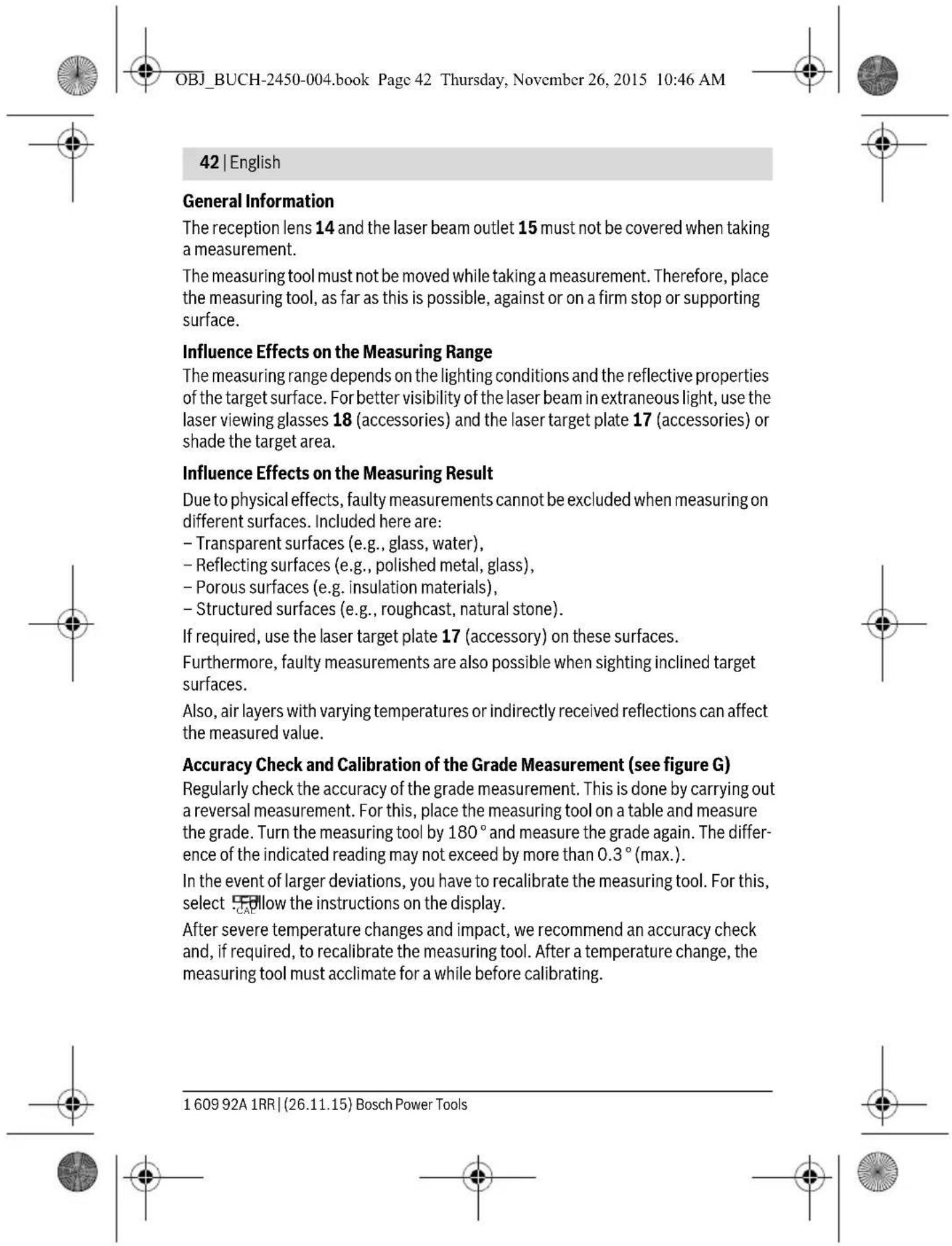
PpOBepKa ToUHocTH KAnH6pOBKa npn H3MepeHHyra HaKHOHa (cm. pnc. G)
Perynphno npOBepnTe ToHocThb n3MepeHHa Yrna HAKNoHa. 3To OcyuceCTBNAeTcnytem n3MepeHHa B DByx HanpaBHeHHx (Tyda H o6pTaHO).IJa 3TOrO NIOXHTe n3-MepntbHbN IHcTpymeHt Ha CToN H3MepbTe yron HAKNoHa. NobepHnTe n3MepnTe bHbN IHcTpymeHt Ha 180° N CHOba n3MepbTe yron HAKNoHa. Pa3Hnca OTObpaKaemOro 3HaueHH He DoJKNHa PpeBbIaTb MaKc. 0,3°
Pn60nbuxOTKIOHEHxN3MePnteBbHINHCTpyMeHT CneIyETOKaHbPOBaTb 3aHOBO.Ⅱn3TOBO Bb6epTe CAL.CneIyTe yKa3aHnM HaIHCnnee.
Iocne cnIbHbIX nepenadOB TeMnepaTypbI Iocne ToUcKOB MbI peKOMeHyem IpOBeCTN npOBepKy TOnHOCTN I npn Heo6xOJIMOCTH Ipon3BecTn KaJIb6pOBky N3MeprTeNbHO rNCHrpyMeNTA.Ipn nepenadaX TeMnepaTypbI daHTe N3MePHTeNBOMy INCTpyMeHTY CTA6HIN3HnPOBaTB CBOIO TeMnepaTypy, npexJe Yem IpON3BOJHTb erO KaJIb6pOBky.


Pycckn | 333
PpOBepKa ToUHocTH N3MepeHHpaCToHHN
ToHocb H3MePHTeBHO rHcTpymHa MoXHo IPOBepnTcJeIyoUIM 06pa3OM:
Bb6epHTe He MeHnIouuIc TceueHEm BpeMeHH yAcToK dInHOJ OK.3-10M, DnHa KOTOPoBaTmTOUHO h3BeCTHa (HaNP., WnpHa NOMEeHn, DBePHo NPOeM).N3MepeHne CLeNyET npOBOnTb npN 6laonpNtHBix YcNoBnx,T.e.yaCtoK DoJIkeH HaxOHTbcB R NOMEeHH n NOBepXHOCTb CEHN DOJIxHA 6bITb rJaIKoN XopoWo OtpaKaTb.
- Ppomepe Te yuaTOK 10 pa3 npDpaI.
OTKIOHeHne pe3yIbTaOB OTdIeIbHbIX N3MepeHn O TcpeHero 3HaueHn He DoJXHO np6IaIopnIHTbIX ycIOBHX IpeBbIwaTb ±4 MM Ha Bcem yuactke.3aIpoToKoHpyTe N3MepeHn C TEM, YTO6bl BNOcIeDCTBm MOxHO 6blO cpaBHnTb ToUHOCTb.
Pa60Ta co wTaTHBOM (npHnAdneKHOCTn)
PpHMeHeHHe WtTaHbA Oc6eHHO Heo6xOJMo Dn8 60bnxPacCToHH.N.YcTaHOBnTe n3MepntbHbI HNCTpyMeHTpe3b6o1/4"13Ha 6bICTPOCMeHHyIO pNHTy WtTaHbA 19nn Ha 06bUHbI fOToaannapatbI h WtTaHB. IpouHO npHBnHTte HHCTpyMeHT BnHTOM K PnITE WtTaHbA.
YcTaHOBHTe HxOHyIO NIOCKOCb (pe3b6a) nIy I3MepeHnco WtAHBOM, HxKaB Ha KhoNky 4.
Co06eHne o6 own6ke
EcINnH3MepeHne BbIIOHNHT npaBnIbHO HeIb3A,HaIcnPnee OTo6paXaeTc coo6- 1e HnOw6Ke «Error».BbIKIOUHTe n CHOBa BKIOUHTe H3MePeNTbHbN INHCTpyMeHT,3aTeM HaHHTe H3MepeHne 3aHOBO.

H3mepntbHbHnHCTpyMeHT OTCLeKHBaET npaBnIbHocTb pa6OtB npKaJdOM H3mepeHH. Pn o6hApyKeHH ndeEeKaTa Ha nCnnee oTo6paXaetc TOLbKO IINb H3o6paXeHHb prdOM CmBOJ N H3MePHTbHbHnHCTpyMeHT BbIKIOuaeTc. B TaKOM cNyue OTnpaBBTe H3mepntbHbHnHCTpyMeHT uepe3 Mara3HN B cepBNCHyO MaCTepCKyIO Bosch.
TexobcnyxmbaHne n cepBnC
Texo6cnyxmbaHne n ouhctka
CopekHTe H3mepHtBbH INHCTpymEt NocToHHo B YnCTOte.
HnkOrda He norpykaTe H3MepntelbHbI INCTpymeHT B BODY nI npyTne XnKDocTn. BblnpaTe 3arpa3HeHn CyxOn mRkOu TpAnKo. He nCnONb3yNe HnKaKx Ounua- loux cpeCTB nI npactBopnten.
Bosch Power Tools 1609 92A 1RR| (26.11.15)


334|Pycckn
YxaxnBaTe 3a npHemHOIINH3O14 cTaKoJKe TuaTeJIbHocTbIO, cKaKoB Bby yxaXnBaTe 3a OUKAMN ININH3O fOToaAnnapata.
Ha pemOH T OTnpaBnIe H3MepeHTeHbHbH NHCpymeHT B 3aLTHOM qexJe 16.
CepBnC n KOncyIbTnpOBaHne Ha npEmdTe HcNoIb3OBAHH npOdyKcHn
CepBnchA MaCTepckA OTBeHT Ha Bce BaHn BOpocbI no peMOHTy n O6cnyHbAHnIO BaHrO npOyKta I NO 3aNpactm. MoHTaXhble YepTeKn HnΦopMauHIO NO 3aNpactM Bbl NaDeTe TaKke No aDpecy:
www.bosch-pt.com
KoJIeKTHB COTpydHnKOB Bosch, npedocTabraUOuN KOHCyIbTaUuHa npedMeT nCIOJIb30BaHHa npOdykun, cyOBOJbCTBHeM OTBeTHT Ha BCE BaUN BOIpocbI OTHOCHTeBHOro HaWe npOdykUn He npHAnDeXHocTe.
IopKanyIcTa, Bo BceX 3aPocax H 3aKa3ax 3aJuaCTe O6raTbeO yKa3bBaIte 10-3HaHbI TOBapHbI HOMep no 3aBOdCKo Ta6nUke N3denn.
BauytnHcKoe Wocce, Bn.24
141400,Γ.XHMMK,MockOBckaO6J.
Pocn
TeN.: 88001008007 (3BOHOK no Pocnnb6ecnnaTbH)
E-Mail: info.powertools@ru.bosch.com
IOnHyIO nAkyalbHyIO HOpMaunIO o pacnoLooKeHHn cepBnchblx ceHTPOB n npHmblx nyHkTob Bbl moKeTe noyntb:
-Ha oΦnuaJIbHOM caIte www.bosch-pt.ru
- nIb6o no TenefoH cypaBouHNo - cepBncHo cnyx6bl Bosch 8 800 100 8007 (3BOHOK no PocCnn 6ecnnaTbn)


YkpaIHcbka
Bka3iBkn 3 texhikn 6e3nekn

IpouHTaTe BcI BkazIBKn I doTpmytecaix, 0o6 npauobatn 3
BHMipOBaHbHm IHCTpymeHOM 6e3neuHO ta hadiHo.
BHKOpHCTaHHB HMipOBaHbHorO IHCTpymeHa 6e3 DoTPMaHHa
UHX IHCTpyKuIM MoKe npN3BeCTn DO nowKOJxehnn
iTERpOBaHNx 3axnCHnx Mexahi3MiB. HikOnn He doBODbTe
nonepexkybanbi Ta6nukn Ha BmipobanbHomy IHctpmeHtdo Hebni3HaHHocti. IO6PE 36EPIaHTe U BKA3IBKN IpePdABaHTeIX PA3OM 3 BmIPIOBAJIbHM IHCTPMEHTOM.
06epexho-BNKOpncTaHHa3ac06iB 06cnyroByBaHHiaHactpoOBaHHa BIDpi3HnTbcB iD 3a3NaeHHx B ciin HCTpyKci, a6o BNkOpncTaHH aO3BOeHHx 3ac06iB y Heo3BoneHH cnoci6, MoKe npn3BoHTn Do He6e3neuEHx B6yix BnnpomIHOBaHH.
BmipobalbHn IHctpymeHT nocTauacTbcra 3 nonepeJxBybHIO Ta6nUko (Ha 306paXeHHI BmipobalbHoro IHcTpymeHTy Ha cToPiu3 MaIOHKOM BOHa No3HaueHa Homepom 12).
IEC60825-1:2014 <1mW, 635 nm
Laser Radiation Do not stare into beam Class 2 laser product
Ykto TeKCT nonepdxyBaIbHOI Ta6nHcN He Ha MOi Baoi KpaIH, 3akneTe HOro neped nepoE kcnnyataucicIO daHOHaKneKOHO MaOBI Baoi KpaIH.
He HanpaBnIte Na3epHn npomInb Ha IIOeN a6o TBapHN, i cami He DnBItbcra Ha npamn a6o BiO6paxyBaHn Na3epHn npomInb. BIn MoKe 3acnInTu INhux IIOeN, cnpuHHnTn HeaacHi Bnpank a6o noKoDHTn Oci.
Ypa3i notpannaHHn na3epHoro npomeHa BOKO, HABMNcHe 3anIOuIb ooyi i BiDpa3y BiDBepHITbcBid npomeHa.
HiorHmHnreBnaepHomypnctpoi.


YkpaIHcbKa|337
He BHKOPHCTOByIte Okynapn dIpo6OTn 3 na3epom B JKOcTI 3axncnX okynarpB. Okynapn dIpo6OTn 3 na3epom npni3auehi dIra Kpaioro po3ni3HaBaHHra3epHOro IpomeH, aIe BOHN He 3axnuaIOb BiJ na3epHOro npomHH.
He BHKOpHCTOByTe OkyIaRn DnApo60TH 3 na3epom dA 3axncty BiD coHcra i 3a KePMOM. OkyIaRn DnApo60TH 3 na3epom He 3axnlaHOb NobHicTIO BID YΦ- npOMHH I noripswuToB po3ni3HaBaHH KOnbopIB.
Bidabate CBH BmipobanbHn npnaHa peMOHT nwe KBaniifikobAHM axibraMa Ta hme 3 BkOpctaHHm ophrinahbx 3aactn. Tlkbn 3a Taknx yMoB BaW BmipobanbHn npnaI i HanaI 6ye 3aHwaTnc 6e3neuHm.
He 03B0nIe dIaM KopncTyBaTHc6e3 Harny naepHm BImipIOBaIbHm npnaDom.BoH MoKyt b HeHaBMnCHe 3acnInTN iHxN x IIOJe.
He npaioTe 3 BmipIOBaIbHnmpnaOmycepeoBnui,deiChyE He6e3neKa Bn6yxBhacniOk npncTycoTcTi rOpoux piHH,ra3iB a60 nHny.Y BmipIOBaIbHOMy npnaDi MOKyTb yTBOPIOBaTHCiaCKPN,Bid knx MoKe 3aImatncn a6o napn.
06epexho!PnBnBkOpncTahHi BmipOBaIbHoro IHcTpymEny 3 Bluetooth MoKnBi nepekoDn dna iHnx npnaadib iyctahOBok, nitaib i MeuHcBkAn anapatIB (HaNP., KApIOCTMmYnAToPiB, CnyXOBx anapatIB). KpIM TOrO, He MOxHa NOBHICTO BKNIOUHTN MOXINBicTB 3aBADHHaKOHNIOJAM i TBAPNHAM, 3NaHXoJrBCB 6e3NocepeHni 6n3bKocTi. He KopNCtuyTEcB BMIPOBaIbHM IHcTpymENTOM 3 Bluetooth no6n3y BiMeuHcBkAn anapatIB, 6EH3OKoLHOK, XIMiUHx yCTAHOBOK i Tepntopii, Ha AKNx icHyE He6e3neKa Bn6yxib a60 MoKyTB npOBODNTCn iIDPNBHpOBoTH. He KopNCtuyTEcB BMIPOBaIbHM IHcTpymENTOM 3 Bluetooth B NItakax. HamaraTeCHe BMKAth IHcTpymENT Ha TpNBanNuac 6e3nocepEnhbo Kono tina.
CnoBecn ToBapn 3nak Bluetooth® i rpaqiHi Tobaphi3nKn (norotnn) cTahOBnIb co6oIO 3apecctpoBani Tobaphi 3nKn i E BlaChicToo Bluetooth SIG, Inc. Robert Bosch GmbH BHKopncToBye ci CnoBecHi/rpaqiHi Tobaphi 3nKn 3a niiueH3iEIO.
BmipioBaHn iHCTpyMeHT np3HaueHH nBmipioBaHH BicTaHi, DOBXHH, BcOTn, DnctaHci, KyTb HaxNny, a TAKoK dnn po3paxyBaHH nIoou i 06'EMIB.
Pe3ynbTaTbBmipIOBaHHaMOxHa nepeDaTH uee3 Bluetooth® Ha iHsi npnana.
Texhihndahi
Executive Vice President
Head of Product Certification
Engineering
PT/ETM9


Robert Bosch GmbH, Power Tools Division 70764 Leinfelden-Echterdingen, GERMANY Leinfelden, 10.11.2015
3o6paxei KOMnoHeHTn
Hymepaui 3o6paKeHHX KOMHOHeTIB NocHaTebca Ha 3o6paKeHHBIMIPBOaIbHO npiaNy Ha CTOpIHc 3 MaJIIOHKOM.
1Диспnett
2 KhoNka BmImpioBaHHa[
3 KhoNka OC [+]
4 KhoIka Bn60py 6a3OBoI nlouHH
5BmMkau[
6 KhoNka Bluetooth®
7 Khoinkapekmy [Func]
8 KhoNka «MiHyc» [-]
9KpnuKa cekuiI dna 6atapenoK
10Φikcatop cekii nla batapeok
11 CepiHnH Homep
12 PonepejkyBaIbHa Ta6nUka Ia npo6Otn 3 na3epom
13 Pi3b60Bn OTBip IaI WtaTnBa 1/4"
1609 92A 1RR| (26.11.15) Bosch Power Tools


YkpaIHcbKa|341
14 Prinomha liH3a
15 Buxid na3epHoro npomehn
16 3axncha cymka
17 Bi3nρha Mapka*
18 Okypan npIpo60n3 naeporm
19UtaTb
*306paxkehe uonncane npnnae He HaneKHTb do cTaHapTHoro o6cary noCTaBKn.
INdikKatopn(Bn6ip)
a Ctah Bluetooth®

Bluetooth® yBIMKHeHn, 3'eHaHH He BCTaHOBNeHe

Bluetooth® yBIMKHeHn, 3'eHaHH BCTaHOBNeHe
b Ba30Ba nIooHnHa npn BmipOBAHHi
C INHnKaTOp 3apJxKeHoCTi 6aTapei
dBmipnHa3naeHHa
e Peaynbat
F PeKHMN BHMIpHOBaHHA
gIhDnKaTOp KyTa HaxHny
H PAnok Ctany
i Ba3oBi HanaWtYaBaHHa
MoHTaK
BctablenHa/3amHa 6atapeiok
Y BmipIOBaIbHOMy npnai peKOMeHnycBHKOpNCTOByBaTH IyXHO-MapraHcEBi 6batapeKN a6o akymyIaTOpHi 6batapei.
3akymyIToPnHm6aTapeMnHa 1,2 BMOxHa BVkoHaTH MeHHe BVMIPOBaHb,HIX3 6aTapeKamnHa 1,5B.
Iio6 biikpnTH KpiuKc kecu i dna 6atapeHOK 9, HATNCihtb pfikcatop 10i3HIMITb KpuiKc kecu i dna 6atapeHOK. BCTPOMiTb 6atapeKN abo akymyIaTOpHi 6atapei. CnIDKyTe npu cboMy 3a npaBnblHM po3aUyBaHHM nOIOciB, kE ne NOKa3aHO BCEpeHNi ceku i dna 6atapeHOK.
Pn nepi ni noiBHa dnCnne i npOxHbOTo cMbOly 6aTapeK, MoXHa BnKOHaTI
ue np6bl.100 BmipIOBaHb.KoHcMbON 6aTapeKn E npOxHIM i Mnae
yepBOHM, noaJIbIi BmIPIOBaHHaHEMOxNBI.3amHITb 6aTapeKN a6o
akymyIaTOPi 6batapei.
Bosch Power Tools 1609 92A 1RR| (26.11.15)


342|YkpaIHcbKa
3aBxM iHnTe oNohacHO bci 6atapeKN/akymyIaTOPHI 6atapei. BnKOpHCTOByIte IInse 6atapeeKn a6o akymyIaTOPHI 6atapei Ondoro BnpObHKa i OndHaKOBoI eMHocTi.
BnMaTe 6aTapeKn/AkymyIaTOpHi 6aTapei i3 BmipIOBaIbHoro npnaady, kUO Bn TpHbAnN Yac He 6yDte KOpHcTyBaTHc npnaADom. Pn TpHbAlOMy 36epirAHHI 6aTapeKn Ta akymyIaTOpHi 6aTapei MoKyt b KopodyBatn i camop03paJxatncr.
Ekcnnyatazaia
PoyatoK po60Tu
He 3annaaTe yBIMkHyTH BHMipIOBaIbHn npnaD 6e3 dOrnay, nicra 3akInueHH po60Tu BMMkaTe BmIPIOBaIbHn npnaD. Hwi oO6n MoKyTb 6Ty n 3acinIIneHi naepHm npomeHem.
3axnauaTe BmipHOBaHbHn npnaB Bd BOrH i coHryHx npomeHib.
He donyckaTe BnHbHa BmipOaBbHnn npnaedekTpeMaIbHnx temnepatyp Ta TemnepaTyphnx nepenadib. 3okpema, He 3aIIuAte Horo Ha TpBaHn yac B MaunHi. RaKIO BmIpOaBbHnn npnaad 3a3NaB BnIbHy nepenady TemnepaTp, nepH hIX BMKaTH NOrO, daTe Homy cTa6iN3yBatn CBOUo TemnepaTypy. EkTpeMaIbHi TemnepaTypn Ta TemnepaTyprHn nepenadn MoKyTb NoripSuBaTH ToHnicB BmipOaBbHoro npnaady.
YHnKaIe CnBnX NOITOBXIB Ta naIHnBnBMIpOBAhBO npNaAdy. IicnA cnBnX 3OBHIuHIX BnINBIB HA BmIPoBaJIbN npnaI nepeI noaJIbwoIO po6ToIO 3 npnaIaOM o6OB'3K0BO nepeBiTe TOHICTb po6TO npnaIy (INB. «PepeBipKa ToHocTI BmIPoBaHH BIDCTaHI), CTOp. 352).
BMKahra/BMMKaH
- Ⅲo6 yBIMKHyTN BmipIOBaIbHn iHCTpyMeHT i na3ep, KopoTKo HaTNCITb Ha KHONKY BmipIOBaHHN 2 [▲].
- Uo6 yBIMKHyTN BmipIOBaIbHn iHCTpyMeHT 6e3 na3epa, KopoTko HaTNCiTB Ha KHONKy yBIMKHeHHBUMKHeHH5 [ ]
He cnpmObyTe na3epHn npomHb Ha IIOe i TBapH i He nBtbcy y na3epHn npomHb, BKNIOuAIOUH i 3 BENKO BiDcTaHi.
IIO6 BHMKHYTH BHMIPHOBAHbHN IHCTpyMeHT, yTPMMyTe KNONky YBIMKHeHH/ BMMKHeHH5 [ ] HaTNCHYTOIO.
YpasiBUMKHeHHBIMipIOBaIbHOrIO IHCTpyMeHa3HaueHH,IO 3HaXoIaTbcB nam'rti,i HanaTuBaHHIHCTpyMeHa36epiraIbCra.


YkpaIHcbka|343
PpoeDypa BnMpiObaHH
Iicra yBIMKHeHH BmIPIOBaHbHn IHcTpMeHT3HaXoHtBCaBpeKmIBmIPIOBaHH DOBXHH. InernepeMnKaHHy IHwH pexHM BmIPIOBaHH HaTCHITb KHONky 7
[Func].ObepiB 6aKaHnpeKHM BmipHOBaHH KhONKO 3 [+] a6o KhONKO 8 [-] (INB.《BmipHOBaHi fHyHKuII》,CTOp.344).YbIMKHITb peKHM BmipHOBaHH KhONKO7 [Func] a6o KhONKO HBMIPHOBaHH 2 [▲]
Iicra BmkaHna 6a3oBa nlounHa dna BmipuBaHHa - ce 3aHi KpaBnMipuBaIbHOr npnaNy. L06 nomiHrN 6a3oBy nlounHy, nB. «Bn6ip 6a3oBoI nloounHn》,cToP.343.
PnncTaBte BmipBoaBHH iHcTpMeHT Do 6aXaHOI BNXiDHOI TOKNI BmipBoHH (hanp.,do CTHN).
Bka3iBaK: RaIO BmIPoBaIbHn IHCTpyMeHT yBIMKHynn 3a DONOMOIO KHONKyBIMKHeHH/BNMKeHHra 5 [ ] KOPOTKO HaTCHITb Ha KHONKY BIMIPoBaHH2 [▲], IO6yBIMKHyTH naep.
Ioo6 3iinCHHTB HmipOBaHHa, KOpOTKo HaTNCiHa KHONKY BmipOBaHHa 2 [A]. Iicnra zbo rO Ja3epHn npOMIHb BmHKacTbcr. nnoaJIbWoTO BmIPOBaHHnOBtopitb u npoueDpy.
He cnpmaOByTe na3epHn npomihb Ha IIOe i TBapHn i He nHBiBcay na3epHn npomihb, BKNIOUaIouHn i 3 BENKO BiCTaHI.
Bka3ibKa: BmipIaHe 3HaueHn 3'ABnEtbcra, Ra npabnlo, npotrO m0,5c, MaKcHymUpe3 np6b.4c. TpnbAicTb BmipIOBaHH 3aIeXHTb BiD BiCTaHI, OCBITneHH I Bi6NBHOI 3dAthOcTI cInbOBoI IOBepxHi. PicJzakIHueHH BmipIOBaHH Ja3epHn IpomHb aBTOMaTHUHO BmNKaTeBCra.
Bn6ip 6a30Boi nlouHH (nVB. Man. A)
PnBnMipOBaHHi Bn MoKeTe Bn6paTn Ondy 3 Tpbox 6aObux nIoUHn:
- 3aDnH Kpa BmipIOBaIbHOrO IHCTpyMeHTy (HaPp., npn npncTaBHeHHI do CTIH),
- nepeenii KpaBnMipOBAIbHOro npInaNy (HaNP.., npN BmipOBAHHi BiD kpaHcTOna),
- cepeɪnHa pi3b6oBOrO oTbOpy 13 (HAp.,ДЯ BmMipioBaHb 3i WtAtnBOM).
Дя Вибopy 6a3OBoI nIoUHH HaTnCHiB KhoNky 4. KhonkoI 3 [+] a6o KhoNkoI O8 [-], a6o KhoNkoI O 4 o6epiB 6axaHv 6a3OBy nIoUHH. Iicna KoXHO rYbIMKHeHH BmipOBaIbHOrO IHCTpyMeHTa B kOCTI 6a3OBoI nIoUHH BCTaHOBIOCTbCra 3aHi KpaBmIPOBaIbHOrO IHCTpyMeHTa.
MeHIO «OchOBHI HacTpoiKNI»
LIO6 notpanHTB MeHIO «Ba3OBI halaWtYBaHHa» (i), ytpmmyTe KhoNky 7 [Func] HATNCHYTOI.
06epiB BiINOBiHe 6aOBe HanaTuBaHH i Bnace HanaTuBaHH.
106BnTn3MeHIOBa3OBIHaHaWtYBaHHRA,HaTHCHITbBA BmKa45 [
Bosch Power Tools 1609 92A 1RR| (26.11.15)


344|YkpaIHcbKa
IicbiuyBaHHnHnne
PiicbiuyBaHHnIcHneNoCTiHNOyBIMKHyTe. KIO HIAKI KHONKe He HaTNCkyOHTbC, iDCBIUYBaHHnIcHne3MeTOIO 3aOuaJxHeHH6bTapeNOK/aKyMyJIrTopHnx 6bTaape np6bl.uepe320ctbMaHIe.
BmipioBaIbHi cyHKuii
BmipioBaHHIOBxHH
06epiBpeKMMBIMipIOBaHHIobXHHI
IIO6 yBIMKHYTH Na3epHn Ipomihb, KOPOTKO HaTNCiTB Ha KHONKY BImipHOBaHHA 2 [▲]
1063iINCHHTBMMIPIOBAHHaKOPOTKaHaNTCHITbHaKHONKy BMMIPIOBAHHa[ ]BmipnHe 3naeHHBaio6paKxyTcH aHicnnei.
IJI KOKHORO NOdaIbwoTO BnMIpHOBaHHa,6yNb NaCKa,NOBTopiB 8.890m IINcIIe3H3y,pepeoCTAHHe-HaHIMt.D

TpBaIe BmipIOBaHH
PnTpHbAlOMy BmMipIOBaHHI BmMipIOBaIbHN IpnIaMD MoXHa nepeCyBaTH BiHocHO do ci, BmIpAHe 3NaueHHe aKtyaIi3yEtbc np6bn. KoxHi O,5c. Bn MoXeTe, HAp., nepeCyBaTcB iD CTIN Ha 6aXaHy BiCTaHb, aKtyaIbHa BiCTaHb 3aBXn D BiO6paJxAcTcB HA DCnIeI.
06epitbpeKHMTPnBaIoroBmMipIOBaHHI
IIO6 yBIMKHYTH Na3epHn IpnOMiHb, KOPOTKO HATNCHTb Ha KHONKy BNMipHOBaHHA 2 [▲]
IpecyBaTe BmIPIOBaNII npnIa ITOX nip, NOKN BnH3y Ha DCnneI He BNCBITbCHeo6xHa BiDcTaHb.
KopOTke HaTnCKaHHHa KHONky BmIPIOBaHH2 [▲]nepepNbAc
DexHM TpNBALoTO BmIPIOBAHH.BmIPJe 3HaueHH
11.623m BIDobpaKyETbC3H3y Ha DCnIe.MakcmaJIbHe MIMaJIbHe
BmIPHi 3HaueHHBIObpaKyIObCra HAD Hm.IOBTOpeHaTnCKaHH
Ha KHOJky BmIPIOBaHH2 [▲] NOuHaE HOBe TpNBaJIe BmIPIOBaHH.
TpNBaJIe BmIPIOBAHH aBTOMaTHUHO BmNKaETbcqyepe35XB.


1609 92A 1RR| (26.11.15) Bosch Power Tools


YkpaIHcbka|345
BmipioBaHHn nloui
06epiBpeXHM BmipObaHHnIooi
Iicna zbo rno no cep3i BnMipraTe uHpHy i DOBXHHy, Ra npn BnMipioBaHHIOBxHH. MIX o6oma BnMipioBaHHMa nasephnn npomihb 3aHnHaetbcg yBIMKHeHM. BiPi3OK, 10o BnMipcoEtbca, 6hMae Ha iHdNkatoPi BnMipioBaHHn IIOosi
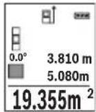
Iepwe Bmiprhe 3haeHHB BiObpaKyTbcra Ha dncnnei 3Bepxy. I0 3aBepseHHi dpyroTO BmipIOBaHHa NIOua aBTOMaTHHO BnpaxoByTbcra i BiObpaKyTbcra. KInueBn peynbTaT BiObpaKaTebcra Ha dncnnei 3HN3y, OKpeMi BmipIOBaHI 3HaueHH NaHIM.
Bmipobahna 06'emy
06epiB pexMM BmipIOBaHHa 06'emy
Iicna zbo rno no cep3i BnMipraTe uHpy,doBXHHy i rnn6Hy,ay npn BnMipioBaHHIOBxHH. Mix cmm TpbOMa BnMipioBaHHMa napeHH npomih 3aIIuHaCTbca yBIMKHeHM. BiDi3OK,uo BnMipocTbcra, 6nMa e Ha iHdkaTopi BnMipioBaHHo6'emy
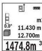
Iepwe Bmiprahe 3haueHHBIO6paXyTebCnHa dnCnnei 3Bepxv. I0 3aBepseHHi dpyrOro BmipIOBaHH nloua aBTOMaTHo BnpaxOBYtbcra i BIO6paXkaTebCn.KIncEbn pe3ynbTaT BiO6paXyTebCnHa dnCnnei 3HN3y, OkpemIBmIPIOBaHI 3haueHHa - HAD HIM.
Henpame Bvmipobahn BiDcTahi
Henpme BnMipIOBaHHB iDcTaHI MOxHa 3iHCHIOBaTH B TpbOXpeKIMax BnMipIOBaHH, B JIKX MOxHA BN3HaayTpiHi BiDCTaHI.
3a DonomoroHneprmoBnMipOBaHH BicTaHIO MoXHa BmIpOBAH BiDcTaH, RKe He MoXHa BmIPATn PpMM NjxOM, KkUo Ha TpaKTopi IpomeH icHyec nepeWKoDa a6o HemaC nIbBOOI NOBepxHi, Ka 6 CnyryBaN B kOkt pePfkeKTopa.
Lcienocic6BmipobahnMoKHa3actocobyBaTHIINeB BepTKaHOMy HAnpMky. Byb-ke BiXnHeHHBropn3OHTaHOMy HApRMky npn3BOoHtB DO NOMIOK B BmipobAHHi.
Bka3ibKa: Henpme BmipioBaHH BicTaHe 3aXKn MeHToH eHX npame. Ioxn6kn BmipioBaHH MoKyTb, 3BaKauOn Ha cneuΦiKy 3actocyBaHH, 6ytN 6ilbHMn YIM npn npamomy BmipioBaHH BiCTaHe. JIra 36IbWeHH ToHocti BmipioBaHH MnpaHMO BHKOpNCOTByBatn StTaNB (pnpna).
B nepepbimixokpemmm BmipioBaHHMa3epHn npomih 3aHuaetbca yBMKHyTM.
Bosch Power Tools 1609 92A 1RR| (26.11.15)


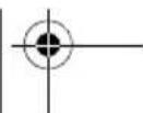


346|YkpaIHcbKa
a) Henpame BnMipIOBaHHB HcOTn (INB. Man. B)
ObepitbpeKIMBmipOBaHHBAcoTH
CniKyuTe 3a TMM, 0o6 BmipioBaIbHn IHCTpMeHT 3haxOdBcHa TiJ cami BNCOTi, 1o HxHH ToUkBA MIPIOBAAH. IOTIM HaxNIITb BmipioBaIbHn IHCTpMeHT NO BiHOWeHHo Do 6a3OBoI PNOUIHHN I BmipraTe BiDpi3OK «1», RaI ce pObTuCBy pa3i BmipioBaHH NOBXHHN (Ha DnCIIeI ppeCTabNeHo YepBOHOIO NiHicIO).
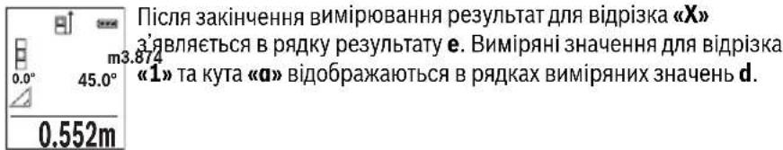
b)Побиин electrme BmipobanBHCOTn (Hb.MaI.C)
BmipobalbHH iHctpMeHT MoKe HnPMAOBmipobatu Yci BiDpiK, 103haxoTbCay BepTKaIbHi nIoUHI BmipobalbHorO IHctpMeHa.
06epiBpeXHM NOdBHORHeHPaMOrBO BmipOBAHHB BOCTH
BmipraTe, i npn BmipHOBaHHIOBxHHN, BiPi3KN 1T a 2B 3a3HaueHIN oocliIOBHOCTi.
c) Henpame BnMipIOBaHHaOBoXHH (Hb. Man. D)
06epitbpekHm HnpeMOro BmipHOBaHHaOBKHN
CniKyuTe 3a THM, 106 BnMipIOBaHbHn npHaad 3HaxOdHBc Ha Odni i Ti cami BncoTi, 10 i Touka BnMipIOBaHHa, kky Bn Bn3HaayeTe. HaxNITb BmIPIOBaHbHn npHaad BiHocHO 6a3OBoI PLOUHN Ta BnMiprTe BiDCTaHb «1», kN npN BnMipIOBaHHIOBxHH.
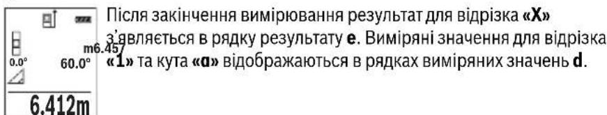


YkpaIHcbka|347
Bmipobannnnooi ctiH (nB. man. E)
BmipobAHn nloi ctiH Do3BOJAE Bn3HaHTN 3araIbHy nlouy deKInkox OkpeMHX dINrHOK, 0o MaIOt b ODAHAKOBY BNCOTy.
Y HabeJeHOMy npKnaJI Heo6XiHNO OToPMaTH 3araIbHy nIOuy DeKeINbKOx CTIH 3 ODAHOBOI BnCOTOIO KIMHaTHN Ane pi3HOIO DOBXKNHOLO L.
06epiBpeKHM BmMIPIOBAHHIIOOJI CTIN
PomiprTe BnCOTy KIMHaTHN H, kZe po6ntbcy pa3i BMIpOBaHHaDObKHH. BmipraHe 3haueHHaBIO6paKaetbcy y BepxHbomy prkny. Na3ep 3aIIuHaecbcy yBIMKHeHM.
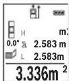
Tenep nomipraTe doBxHnHy L1 neploi cTInn. IIOuia niIpaXOByEcTbca ABTomaTHUHO i Bka3yeTbcry pRky pe3yIbTaTy e. OctaHHe 3NaueHHB MIPRAHOI DOBxHHN Bka3yeTbcry HNXHbOMy PAnky d. Na3ep 3aIIHaCTbcra yBIMKHeHm.
Tenep nomipraTe IOBxHny L2 dpyroI cTIHN. Bkaaane y pRky BmipraHnx 3HaueHb d Okpeme BmipraHe 3HaueHHa DOnaEtbcra Do
DobxHnL. Cyma o6oX doBxHn (BIO6paKaCTbC y cepEnhomy PAnky BmipnHex 3aueHb d) NOMHOxyCTbCn Ha 36epexeHy B nam'Ati BncoTy H. 3aueHHa 3aIaNbHOI pIoU iBIO6paKaCTbCn y prkny pe3yNbTaTy e.
MoKHa nomipTn 6yIb-ky KInbKiCTb DOBxH Lx, kI aBTOMaTHUHO DoaIOTBcI NOMHOxKyTObCa Ha BnCOTy H.
I npabHbHO BmipobAHn Hnoi Heo6xH0, 06B HmipraHa nepwa DOBXHa (y npknad i - Bncota KIMHaTH H) 6yna ideHTNuHO O nla ycix OKpeMnx nlou.
PexHM po3MitKn (nB. Man. F)
YpeKMIpo3MITKNIOCTIHOBIDMIPJOITBCBAka3aHI DOBXHHN(BiDCTaHI).CIIOBHXHMOxHa nepeHocHTHa NOBepXHo, HAp., DnA BIDpi3AHJ ODAKOBHX BiDpi3KIB MaTePiaIy a6o MOHTaxy Kapkaca dIINCOKAPTOHoi 06WNB. MoXJIbMaMHImaJIbHa IOBXHHa cKnadae 0,1 M, MaKcIMaJIbHa DOBXHHa cKnadae 50 M.
06epitbpekmpo3miKn
BkaKITb6aKaHyDObKHy.DIyIbOroKHOHKOIO7[Func]06epiBbiJNOBIHy uNphipy/po3pndI3miHITb3HaueHHKHOKNIO3 [+ ]a6o KHOHKOIO8[-].
YbIMKHTb peKHM pO3MITKN KHONKOOB BMIPIOBAHHa2 [▲], i NobiNbHO BiDaaJIaTeCa BID NOuATKOBOI TOUKN.
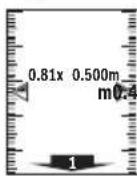
BmipobbHn iHcTpymeht 63nepebpBO Bmipioe BiDcaHb do noatkoBoi TouKn. Pn cybomy BiO6paXaOTbcra Bka3aHi DOBXHN TaIOTouHe Bmipane 3HaueHn. Bepxna 60 HnKna CTpiKa BkAsYe Ha NaMeHsy BiCTaHdo HAcTyHoi a6o MInHyOni BiDMtKn.
Bka3ibKa: Raio nid yac TpBaIoro BmipIOBaHHaHTnCHyTH KONky 4, MoXHa 3aDAn BmIPReH 3aueHHaIKoCTi Bka3aHOJOBxHH.
Bosch Power Tools 1609 92A 1RR| (26.11.15)


348|YkpaIHcbKa
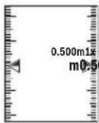
Koephiicnt nibopyu Bka3ye, cikbn pa3iB 6yna docrahyta Bka3aHa DOBXnHa.3enehi ctrpinko ab6iu dncnnre BkazyIOb Ha DoCraHHeHH Heo6xIDHOI DOBXHNn DnBa BiPi3Ka, 0o BiMiaacTbcr.
BmipobAHHaKyTb HaxHy/4nΦpOBN BaTePnac
06epitbpeKHM BmipIOBaHHK KyTIB HaxHy/UnΦpOBO RaTePnaca
BmipioBaIbHn iHCTpyMeHT aBTOMaTHUHO nepemHKaETbcra MIX ZHMN DBOMa peKIMAMn.
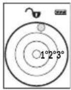
UHPOBn BatepnaCnyrE nIpebipKn rOpN3OHTaJIbHOCTi UH BepTKaJIbHOCTI NOJKeHHo6'EkTa (HaNP., npalboMauHH, XONODINbHnKa ToIO).
Ypasi nepeBnueHHaHxNHy 3^ KynbKa Ha nCnIeI rOpNTb YepBOHm.
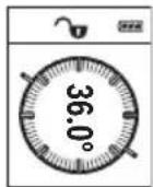
PexnBmipIOBaHHa KyTa Haxnny Cnyrye Dna Bn3HaueHnnaIiHomy a6o haxnny (hnp., cxoobnx xidHB, npuyHB, npni nroHcMe6nib, npn npoklaadHHI Tpyb Toio).
Ba3OBOI pIoUHIOI DIA BmIPoBHaHH KytA Haxnny E IiBn KpaBmIPoBbHorO IHcTpymeHT. RaIIO nIac Oepaui BmIPoBHaHH Mrrae iHdkatOp, TO BmIPoBbHn IHcTpymeHT 3aHaJTO CXHeHn B6ik.
Функци nam'ari
3HaueHHa60peaybTaT KOxHOrO OKpemOro BnMipHOBaHH 36epiraetbcB nam'rI aBTOMaTHUHO.
Biodo6paKeHHa3epeXeHnx 3HaueHb
BnKInKaTu MoXHa He 6IbWe 30 3HaueHb (BnMipRnX 3HaueHb a6o KInCeBnx pe3yNbTaTb).
06epitbdyHKJIO nam'rti
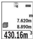
3BepxHa nCnnei BiO6paXyETbC Homep KOMIPKn Na'M'ti, 3Hn3y - BInnoBIDHe 36peXeHe 3HaueHHa a 3JIba-BiIOBIDn peKm BIMIpOBaHH.
HaTnCKaIe KHONKy 3 [+] ,IO6 npokpyyBaTH 36epexKeHI 3haueHHBnepei.
HaTnCKaIe KhoNky 8 [-], IIO6 npokpyyBaTH 36epexEHI 3haueHH Ha3aI.


YkpaIHcbka|349
JaKo y nam'rTi HeMae 3HaueHb, 3Hn3y Ha DnCnnei BiO6paJxEYc8a0.000', a 3BepxY - «O».
Haicapiiwe 3haeHHra 3haxoHbCry y nam'rti Homep 1, haiHObiue - Homep 30 (rkio e 30 36epexehnx 3haeHb).Ppi 36epexehn HOBOrO 3haeHHraBxdi BvdaJIaETbcra Haicapiwe 3haeHHra.
CTnpaHHBmictyNam'Ati
IyOuHHeHH 3MCTy Na'M'RTi HATNCHTb Ha KHONKy 7 [Func] i oBepiB cyHKuiO nAM'RTi . NotIM KOPOTKO HATNCHTb Ha KHONKy yBIMKHeHH/ BIMKHeHH 5 [ ] ,06 BnDaIaNTn BiO6paXeHe 3HaueHH.
Ypa3iOndHouachoroHaTnCKaHHKHOKN4IBMnKaay5[0]BnDaIaHTbcyci 3NaueHH,IO3NaXoRbCryNam'rti.
IodabAHHb/BiDhImaHH3HaueHb
Bmipnhi 3haeHH a6o kiHueBi pe3yntMoKHa oDaBaTH a6o BiHimTu.
IodabahnH3naueHb
YHaCtynHOMy npKnlaI nOaEbC8 ONc DoBaHnHIIIOU:
BnHaute nioy 3riHNO 3 po3iIOM «BmipIOBaHHI Iooi」,INB. cTOp. 345.
HaTnCHiB KONky 3 [+] BiO6paXaOTbcNippaXOBaHa nloua i CMBON «+».
HaTnCHiB Ha KONky BmIPoBAHn2 [▲], zo6 po3noatn HOBe BmIPoBaHHn PNOU. Bu3NaHTe PNOUy 3rIHO 3 po3INOM «BmIPoBAHHn PNOU, DN.B. cTOp. 345. Odp3y no 3aBepWeHHi DpyrO BoMIPoBAHHpe3yNbTaT DpyrO BoMIPoBAHHn PNOU BID6paXaTcB HnKHi qactnHi DiNpne. JnB BiO6paXeHHn KInCeBO r pe3yNbTaTu ye pa3 HaTnCHiB KONky BmIPoBAHH 2 [▲].
BkaibKa: y pa3i BmipIOBaHH IOBXHH pe3yNbTaT BiO6paKaetbCh Opa3y.
IIO6 BnITn 3 peKIMy IoJaBaHHa,HaTNCiHb Ha KOnIKy 7 [Func].
BiDhimaHHaHaeHb
IIO6 BIKKohatn BiDhimaHHaHaeHb,HaTNCHTb KhoNky 8 [-].IpaJIbwi iIi anaIorIuHi «IOnBaAHHH3HaueHb».
CTipaHHBmIpAHHx3HaueHb
KopoTko HaTnchBnHa KhoNkY yBIMKHeHHBbMKNHeHH5 [c] Bycix pexkmax BmipIOBaHH MoXHa BnDaJIHTn OCTaHHe OTpMaHe BmIPIOBaHe 3HaueHH. DeKlbOMa KopoTknMn HaTnCKaHHMa H KaONky yBIMKHeHHBbMKNHeHH5 [c] BmipIOBaHi 3HaueHH BnDaJIOTbcr Y 3BOpOTHomy npRdKy.
Bosch Power Tools 1609 92A 1RR| (26.11.15)


350|YkpaIHcbKa
3MiHa ODNHHU BHMIPIOBaHHA
y6a3OBHX HAJIaWtYBaHHX OINHnueo BHMIPIOBAAHBACTAOBHeHm «m» (MeTp).
YbIMKHiB BmipOBaIbHn iHCTpyMeHT.
Ytpmyte KhoNky 7 [Func], 06 npeeHTB MeHIO «Ba3Obi HanaWtBuHHa».Obepitb «ft/m»
HaTNCiHb Ha KHOIky 3 [+] a6o Ha KHOIky 8 [-], 0o6 3miHHTn ODNHHIO BmipIOBAHH.
IIO63aJIINHHTNnyHKMeHIO,HaTNCiTB HaBIMNKaY5 [c]。PiCnBIMKHeHHBIMIPHOBaHOrO IHCTpyMeHTy 0bpaHe HanaTuBaHHa 3aIIuAeTbc36epexKeHM.
Intepfenc Bluetooth®
Ipepaa daHHx Ha iHwi npnana
BmipBoaHn iHcTpymeT oHaHaHm Moynem Bluetooth,Akn Do3BOJNEpeDaBaTH DaHI 3a DonomorOpaIotexHikn Ha DeKIMo6Inhki KINHeBi npCTpoi 3iHTepfchcom Bluetooth(Hanp.,CMapToHn,PnAHWeTHNk)
Ihopmaio 0oOcHmHx nepeymOB n3'eHaHHnB lueothn. Ha caTt Bosch
www.bosch-pt.de
BilbouoknaHa iHPhiopMaui 3haxOuHTbcHa cTOpIHui npOdyKry Bosch,INB. QR-KoIc,ctop.8.
Pn npepaui daHnx uepe3 Bluetooth® MoKnBi 3aTpHMKn MxK Mo6IbHM KInCeBmnpctpoem i BmipHOBaHm IHctpMeHTOM. Lc MoKe 6yTu NOB'raHe 3 BiDCTAHIO mK o6Oma npnaadamn a6o i3 camHm BmipHOBaHm O6'ekTom.
Akhbaiai iThepcecy Bluetooth® dna nepepaui daHnx Ha Mo6inbHn KInceBn npncptpi
ДлгakTNBaцii INTepefeyCy Bluteoth® HaTNCiTB Ha KhoNkY Bluteoth® 6Ha BmipIOBaIbHOMy IHCTpyMeHTI.ДлгakTNBaцii CnRhany Bluteoth® ue pa3 HaTNCiTB Ha KhoNkY Bluteoth® 6 a6o Ha KhoNkY 3 [+].BneBHITbc,Io INTepefeyC Bluteoth® Ha BaIOMy MobinbHOMy KInceBOMy npncTpoI akTNBOBaHH.
He BnKndaTe BmipIOBaJIbHI iHCTpyMeHTa akymyIaTOpHi 6aTaapei/6aTaapeeKnB no6yToBe CmTTT!
Jnne nKpaH EC:
BidnoiHdoEbponecbooiHpeKTHBn2012/19/EU ta
eBponecbooiHpeKTHBn2006/66/EC BIDnpaobaHi
Bmipobalhi npna, noWkoJxHei a6o BiDpaocBaHi
akymyIaTOpHi 6ataei/batapeKN nobHHI 3daBatncr Okpemoi
ytni3yBaTncr ekonoiuHOn uCTHM cnocobom.
Moxnbi3minH.

Kaazakwa 355
Ka3akwa
Caikeckti pactay xehiHderi aknapat KantamahbIH KocbIMwacbHa 6epinei.
EHnpy KyHi HcaynbIKbIH COHfBI, MyKa6a 6etInHe KepcetinreH.
MnopTaybI KOHTAKTIK MmimetIH opama Ta6y MyMKH.
Ohini nai danany Mep3imi
ΘHimH Kbi3metety MEPimi 7 kbl. ΘHdpinreH MEPImHen bactan (eHdpy Kyhi 3aybTTaKtaWacBHaJka3bIFAH) icTeTne 5 kbl CaKaTaFAHHaH coH, eHIMdi TEkcepyci (cepBnCTIK TekcepY naDanaHy cBiHmMaIdbI.
KbI3MeTkep Hemece naDanaHyyBbHbH KaTeiikTepi MeH icTeH WbIFy ce6entepinH ti3imi
- eHIM KopnycbiHaH TiKeNeI TyTIn 7bIKca, naIaIaNb6aHbI3
JxaybH-uaaBHKe3iHne cbiPTta(daana)naIandaHaBbI3
Kopnyc iWHe cy Kipce KypbInfBihKocyUbi 60MaHb3
IeKTI Kyn 6enrinepi
- eHIM KopnycbiHbH 3aKbIMdanybl
KbI3MeT Kepcety Typi Men Xniniri
Op naiandaanhyd an coH eHimDi Ta3anay ycblnaabi.
CaKray
KypraKepde caTay KepeK
KOFapbI TemnepaTypa K03iHeH KHe KYH caynepeHH acepiH anbc caKTay KepeK
caKay Ke3IHTeMnpepaTpyaHbIH KeHeT aybITKybiHaN KOpFay KepeK
erep KypaJI KymcaK cemKe Hemece INaCTIK KeIcTe KeTkiSInCe OHbIOcbI e3IH KOpFaBbI KabHda caTay ycbHbIaNbI
caTay wapTapbl typanbl kocbIMwa aknapaT any ywiH MEMCT 15150 (JapT 1) KyKaTbIH KapaHb3
TacbImanday
TacbImaIay Ke3iHne OHIMdi KynatYfa XHe Ke3 KeIReH MExaHKnblk bIKnlaI eTyRe KaTaH TbiBIM CaJIbHaDbl
6ocaty/xyktey Ke3iHne naKeTTI KbCatbIH MaunHaIapDbI naJaHaHyf pyKcat 6epinmei.
- TaçibMaJday waPTapbTaIanTAPbIH MEMCT 15150 (5 wapT) KxKaTbH OkbHbI3.


356|Kaazakwa
Kayinci3dk HycKaynapbI

Onwey KypanbIH Kayinci3 Xe He cemHn i naDanaHy yin 6apnbIK HycKaynapdbI MyKnT OKbn, Xymbc 6apbcBHa eckepiH3. Onwey KypanbIH ocbl HcKaynapra ca nnaDanaH6ay enwey KypanbIHdafti KipictipInreH Kayinci3ik wapanapbHa KaFBIMcb13 acep etedi. Onwey KypanbIHdafti eckeptynepdi
Kepin6eTIN KblMaHbI3.OCbl HYCKAYAPbl CAKTAN,ONLIeY KYPALbiH BACKAIPFA BEPREHIDE ONAPbl KOCA YCbIHbIbI3.
A6aB 60nblb3 -erep ocbl Jepde 6epinreH naDanaHy Hemece Tsy3eTy KypanapbHaH 6acka KypandaH naDanaHca Hemece 6acka Kymbic aictepi opbHdanca 6yn kaynti cayner wanbHyra anbIn Kenyi Mymkin.
Θηωeey KypanbI eckepTy TaKtacbImeH Ka6dbIKTaIraH (ηιωeey KypaBbIHbIH, cypetihne rpaΦnka 6etihne 12 HemipimEnbenrInhen).
IEC60825-1:2014
Laser Radiation Do not stare into beam Class 2 laser product
Erep eckepy xancbipmacbi ci3iH eniH3 tiinde 6onmaca, anfawkbl naandaahyaan aIbIH OHbIH opbHa cI3iH eniH3 tiinHe 6onfaH xancbipmaHbI Xa6bICtpbIHbI3.

Ja3ep caynein aadam Hemece kahyapnapfa 6aftTamaHbI3 Xane 03iH3 de tikeen Hemece wafbinf an3ep caynecine KapamahbI. Ocbna aadamapdbIH Ke3IH waBInDbipyMymKIN, CcTci3 OKnfanapfa anbIN kenyi KHe Ke3di 3akBIMdaybl MymKIN.
Erep na3ep cayneci Ke3re Tycce Ke3eepdi KymbIn 6actbl cayneH apbl KapatyKepeK.
Na3ep KypbIbIbIcBbIHa eWkaHdae 03repTybI opbIHdAmaHbI3.
▶ Μαερ κεργ κεθιπίριρινκορτανβιωκεθιπίριρι petiHne naɪdaɪaɪn6aɪbɪ.
Παερ κεργ κεθιπίριρινλερ cəyηcɪŋ ἀκακсьɪpɑk κεργ yɪsɪŋ Kbɪ3mɪt ḌacaiNbI, 6ipak on nαερ cəyηcɪhen κορfamaiNbI.
Panaanha3. Pae Kepi Keinipiri yIbTpaHnoTeaynepeH ToBk Kopram peKepyKaunetih a3aTabi.


Kaazakwa 357
Θηωe KypaJIbH TEK 6iNkTI MAmHaFα XeHae apHayIb 6eUeKTepeMeH XeHdTeH3. Con apKbInbI eUeWey KypaI Kayinci3diRiH caKaTaNbI3.
BanaIap na3ep enwey kypabIn 6akblaycbn naIdaanH6acbH. Onap 6inMe aamdapdbH Ke3iH Wafblbictbpy MymkIH.
XaHaTbH cybIKtbIKTap, ra3dap Hemece WaH XbINrA H Xapblbc Kayni 6ap optada eNwey KypabH nainanah6aHbI3. OJwey KpaBbI yKbIH WbIFapbln, WAnDbI XaHdbipBn, ePT TyDbIPby MymkH.
A6aB 60nbHbI! OJnwe Kypanbln Bluteoth6eH naDanahyda 6acka Kypannap MeH Xa6dbkTap, ywaK XoHe MeMnunHaNbIK Kypannap (MbicnbI, KapnocmmynTop, ecTy KypandApbl) XymbicbHda Keedeprinep naDa 6onybIMyMKIn. CoHdai-ak XaKaBH TpyFaH aDAMap MeH xaYaNpaFra 3HNr TYdbipy KayniH ToNbIK XOIO MymKH emec. OJnwe Kypanbln Bluteoth6eH MeDnHbIK Kypanlap, XaHap MaB beKeETepi, XHMnabIK Xa6dbkTap, Xapbiny Kayni 6ap XoHe XapblnaTbIH aMaKTap KaHbHda naDanaHbHbI3. OJnwe Kypanbln Bluteoth6eH ywaKTapda naDanaHbHbI3. DeHere XaKbIH aMaKaTa y3ak YaKbIT naDanaHbHaB13.
Bluetooth® ce3 genrici cypet 6enricimeh (norottnep) 6ipre Bluetooth SIG, Inc.
KOMnAnHcBInbH tipKeIren TayapnbIK 6enrici XaHe Myniri 6onbl Ta6bnadbl.
OcbI ce3/cypet 6enricin Robert Bosch GmbH apkbl naDanahy nueH3nHeri3iHde opbHdanaBl.
Ohim XaHe Kbl3MeT CnnaTTamacbl
OJy KpaHbHcpei 6ap 6eTI aWbIn, naJaHaHy HcyKaybIFbH OKy Ke3IHDe OHblawIKYCTaHbI3.
TaFaiBihdany 6oBbHwa KonDaHy
OJy KpaJI KaIbIKTbIKTapbl, Y3bIHbIKTapbl, 6NIKTKePdl, apaJIbIKTapbl, KeBeyepdi OJweye XHe ayHaH MeH ayMaKTapbl ecenTeYre aPhaIIFaH.
Onwey HtXkepeiin Bluetooth® apkblb6acka KypbInfbInapFa eTki3y MymKiH.


358|Kaazakwa
TexHkaJIbIK MJIImeTTeP
| Сандык пазер кашьктук онлайнeriiшi | GLM 50 C |
| Өнім Немір | 3601K72C... |
| Өлшey aiMaftы (а徳Ту儿) | 0,05-50 M A) |
| Өлшey aiMaftы (а徳Ту儿, Калайсыз жаftдai) | 20 M B) |
| Өлшey anБКТыFы (а徳Ту儿) | ±1,5 MM A) |
| Өлшey дәndiri (а徳Ту儿, Калайсыз жаftдai) | ±3,0 MM B) |
| Еніkiші корсeredіпгэн зелем ent | 0,1 MM |
| Жанama кашьктук онлайне Men Deнг'rei | |
| Өлшey aiMaftы | 0°-360°(4x90°) |
| Көнбeydi олшey | |
| Өлшey aiMaftы | 0°-360°(4x90°) |
| Өлшey anБКТыFы (а徳Ту儿) | ±0,2C/D)/I) |
| Еніkiші корсeredіпгэн зелем ent | 0,1° |
| Жалны | |
| Жуmbіс Temператypасы | -10°C...+45°C E) |
| Саftay Temператypасы | -20°C...+70°C |
| Салысты малы aya billymaftы Мамс. | 90 % |
| Пазер сыныпьi | 2 |
| Пазер Тур i | 635 NM, <1 MBT |
| Пазер саунесиндиаметri (25°C Te)шamameh. | |
| - кашьктуы 10 solfaнда | 9 MM D) |
| - кашьктуы 50 solfaнда | 45 MM D) |
| Өшір у втоматникасышamameh төmen德ergideн coh. | |
| - Пазер | 20 c |
| - Θлшey куралы (өлшeyсiz) | 5 MInH) |
| EPTA-Procedure 01:2014 күхатын сай салмafы | 0,10 кr |
| Көнemдер | 106x45x24MM |
| Корfasныс Тур i | IP 54 (шанжэншашьрайын сydан корfasны F) |
| Батареглар | 2x1,5B LRO3(AAA) |
| АKKумлąтopsык онлайнпер | 2x1,2B HR03(AAA) |
1609 92A 1RR| (26.11.15) Bosch Power Tools


Kaazakwa 359
| Санык пазер кашькък сиweriш | GLM 50 C |
| Батаря жуmbic icteу мерзimiшam. | |
| - Б олес сешемер | 10000H) |
| - Удikсizэлшey | 2,5 cH) |
| Өлшey bīрлirin peṭeу | m (м), ft (фут), in (дюм) |
| Деректөрд iтасымалдay | |
| Bluetooth® | Bluetooth® 4.0 (Classic pen Low Energy)G) |
Executive Vice President
Head of Product Certification
Engineering
PT/ETM9

f_( 2) = h · m
Robert Bosch GmbH, Power Tools Division
70764 Leinfelden-Echterdingen, GERMANY
Leinfelden, 10.11.2015
Бeненehren Kypamdbi 6eIweKtep
KepcetinreH Kypamdactap Hemipi cypeTep 6ap 6eTteri enwey KypaIbIHbIH CNnattamaCbiHa KaTbICTbl.
1Dncnnne
2 Θnwey nepheci[]
3Плiocперheci[+]
4 Heri3ri kazbiktbkTbTaHay nepheci
5 Kocy-ewipy Tymeci[ ]
6 Bluetooth® nepheci
7ФункциЯньКпөрHe [Func]
8 MInHyc nepheci[-]
9 BaTape 6eNimi KaKnaFbI
1.0 BaTape8 6eIimi KaKaNaFbIHbH Kynnblb
1.1 CepnIbIK Hemip
1.2 Na3ep eckepTy TaKtracbl
1.3 1/4"WtTaTnB 6ypaHdaCbI
4 Ka6bIyayHnH3acbi
1.5 Na3ep cayneciHH uBfbcbl
6 KopfainbH KaTta
7 Na3ep HbCaHbik TaKaTacbl
8 Na3ep Kepy Ke3inipiri
9 TafaH
*BeHeneHReH Hemece CnnaTaNfAH Xa6dbIKTap CTAHapTTbI XeTKi3y KOnemimekamTbImaNbl.
1609 92A 1RR| (26.11.15) Bosch Power Tools


Ka3akwa|361
Kopcetkiu 3IemeHTep (TaHdaMaNaBt)
a Bluetooth® kyni

Bluetooth® 6enceHdi, 6aHaNbIc JxacanMaDbI

Bluetooth® 6enceHdi, 6aHaNbIc Xacanbl
b Θηιηγεγεπελαβκτιβι
cBaTapeKepcetKiWi
d OIwey KOnemepi kOJaftb
e HətɪŋkeJIep Jɔnəfbl
fThnweydyHkunnapbI
g Ehi6 6ypbblbHbHKepcTeKlui
h Kyi nahaneni
i Heri3ri napaMeTpIep
XnHay
Batapeanapdcbany/anmactbipy
Ouwey Kypanbl yuih ankanin HmapraHec 6aTapecnH HeMece aKKymnTopbH naDanaHy cblbIaBbl.
1,2 BONbTTbIK aKKyMnyTOpMeH 1,5 BONbTTbIK 6aTapeRnapFa cAnbIcTbIPFaHda KEMipeK eNweynePdi opbHday MymKiH.
Batape 6eimih KAKnafbin 9 auy yuih 10bicbpmacbi h bacin, KaKnaktbaiuibH3. BatapeHHi Hemece akymyIaTOpbl caIbH3. Batape 6eimih iH deri cypette KepctinreHdien noIOCTapdbH dypbc opHaIacbyH kAMTaMaCb3 etIH3.
Erep6oc 6atapera 6enrici andbin dncnnepe naia 6onca, onda xhe am. 100 enwemep 6onybmymkiH.Erep 6atapera 6enrici 6oc 6onblk3bl TycTe XaHca, OHda ewhip enwemepdi opbiHdayra 6onmaNbbl. Batape Hemece aKKyMnyTopnapdi anMaTbipbHbI3.
Bapnbk 6batapeanap Hemece aKKymyIaTOpnapdbi 6ipde anMaCTbipbHb3. Tek 6ip eHdpuywiH KHe KyatbI 6ipde 6batapeanap Hemece aKKymyIaTOpnapdbi naHdanaHbHb3.
¥3ak yakbl nai dana h6acaHb3, 6atapeHbI He mece akkymyIaTOpnapdbI enwey KypanbIHAn anbIN KObIHbI3. ¥3ak yakbl JkaTKaH 6atapeHap He mece aKKymyIaTOpnap TOB bacybl XHe 3apdibH XoFAJTybl MymKIn.


362|Kaazakwa
Пайдалиану
PaiandaHyra eHdpy
KocynbI 3apTay KypabH 6akblaycb13 KaandpMaHb13 XHe enwey KypabH naDanahydah coH ewiipi3. Naep cayneimeh aamnapdbH Ke3IH WafblbCTbpy MymkiH.
Θnwey KypaibH cbI3dAn Xe Hte TikeNe KYN cayenepeiHe CaKtaHbI3.
Θnwey KypaIbHa anpblka TempepaTypa Hemece TemnepaTypa tep6enepi acep etneyi Tnic. OHblMbCaIbI aBTOkeJIkTe y3ak yaKbIT KaIbIpMaHbI. YIKeH TempepaTypa Tep6enepi KaFaDaIbIHda anDbIMeH onWey KypaIbIH TempepaTypacbIH dpybictan coN naJaIaNbHbIb3. Anpblka TempepaTypa Hemece TempepaTypa Tep6enepi KezInde enwey KypaIbIHbIH dAndiT TeMeHdEnyi MymkiH.
ΘηωeY KypaIbIH KaTbI COKKbIaH HemeCe KynaydaH CaKaTaHbI3. CbIPTkbl KyuTi Čeρπερdēn KeiH ΘηωeY KypaIbIHbIH KymbICbIH KaIFaCTbIpyaH aNDbH ĀpàIbIM dənɪk TekcepyiH opbIHday KepeK ("KaIbIKbIKbI ŠηωeYdiH dənɪrH tekcepY", 371 6etIH kapaHbI3).
Kocy/ewipy
- Θηωeу куралы мен пазердій кocу wiyin 2 [▲] Θηωeу nephecihe Кьсka bacbHb3.
- Θηωeγκραβνινλαερci3 κογ γιδινκόγεινηκόγεινηπερηκειν 5 [ ] Kβικαδαδας
- Na3ep cayncin aamapra hemece kanyapnapra 6aftTamaHb13 khe tinti anbictah 6oncbih kapbik cayncinee 3ihi3 KapamaHb13.
Eney KypanbH eupy yin H kcy-ewipy nepheci 5 [ ]6acbin YcTaHb3.
Ouwey Kypabih EiwipreHne Kaanda TypFaH MAnep MeH KypblfblnapaMeTpnepi caKaTanaBl.
Onwey aqi ci
KocyaH coH 0Iwe KypaIbI y3bIbIK OIwey fHyKcIraCbHa TaPaIbI. BacKa 0Iwey FyHKcIraCbI yWIn 7 [Func] nephein bacbIb3KepeKTi 0Iwey fHyKcIraCbIH 3 [+ ] nepheim Hemece 8 [-] nepheim TaHdaHbI3 ("O1wey fHyKcIraNapbl" 363 beTHe kapaHbI). OIwey fHyKcIraCbIH 7 [Func] nepheim Hemece 2 0Iwey nepheim HenepHein HapipH3 [▲] nephein bacbIbI3.
OJnweyin Heri3ri Jka3bIKtbIbI KocyaH COH eJWey KypaJIbIHbI apTKbl KbIPbl TaHaanabI. Heri3ri Jka3bIKtbIbI aImactbpy ywiH "Heri3ri Jka3bIKtbIbI TaHday" 363 betInde kapaHbI3.
Onwey KypanbH enweyein Kepekti 6actay KaibaHa (Mbicanb, Ka6bipfa) 6acbHb3.


Kaazakwa 363
EckepTne: Erep eIwey KypaIbI Kocy-eIipy-nepHecimE 5 [c] KocbInFaH 6oIca eIwey 2 [▲] nepHeciHe KblcA bAcBn Ia3epDi KocbHb3.
Oneuydi icke kocy yuH 2 eIwey nepheine Kbicka bacHBi3 [ ] .CocBn Ia3ep cayneic Ewei. Baca eIwey yuH ocbi aDicti KaTanaHbi3.
- Na3ep cayncin aamapra Hemece xahyapnapra 6afttama h3 xhe tinti anbictan 6oncbn kaybk caync ihe e3ihi3 kapaamh3.
Eckeptne: OIwey KOnemi aTeTne 0,5 cek neh eh y3aftbI wam.4 cek iwiHne naJa bOlaDbI. OIwey y3aKtBfbl KaWbIKtBkTaH, XapblkTBkXafdaNMeH HbicaHdbK aMaKtBn KaTapy KacHeTepine baNaHbICTbl. OIweydi aKaTaraHaHaH coH naep cayneci ABOMaTTb peTte eWedi.
Heri3ri Ka3bIKTbIKTbI TaHday (A cypeTIH KapaHb13)
Ouweywih yw typi Heri3ri Ka3biktbktpabih apacbiHaTahay MyMkiH:
- eIiwey KypaibHbH apTkbl Kbipbl (MbicaB, Ka6bIpFaIapFa KoHaHa),
- eIwey KypaJIbHbIH aNfbl KbIpbbl (MbICaNbl YCTeN KbIpbIHAn OJIweyde),
-6ypaHda opTaCb 13 (MbIcAlb, TaFaHMeH eIWeyJe).
4 nephein heri3ri dehreinyaun ywiH b3. 3 [+] nephecimn He mee 8 [-] nephecimen Hemece 4 nephecimn kepeki heri3ri dehreiny aHaB3. OJwey KypabibHbH ap6ip kocbinybHda oJwey KypabHbH apTKbl KbpI Heri3r Jaa3bIKtbK peTInde anbHah pettenre h obaBl.
"Heri3ri napameTpnep" Məzipi
"Heri3ri napametnpep" (i) m3ipine kipy ywiH 7 [Func] nephecih bacbin yctahbi3. Heri3ri napametpmen 03iH3 napametpiH3di TaandaHbI3.
"Heri ri napametnpep" m3piH hIy ywiH Kocbi-ewipy Tymecin 5 [c] 6acblb3 nepheciH 6acblb3.
Диспней карыгbl
IcnneJXapbIbH y3aK yaKbITKa KocblfHa. Iephe 6acblmaca, dncnne JxapblbIaam.20 ckyHdTaH coH 6aTapeHbI/aKKyMnyTopdbI yHeMdeY wHIN KapaHfbInaHaDbI.
Otnwey yhknnaapbl
¥3bHbikTbl enwey
1y3bIHdbkTbIeHweyI TaHaHbI3.
Ja3ep cayncin Kocy yuih 2 [ ] enwey nepheine Kbiicka 6acbHbI3.
OneyuywH2[ ] Oneyey nephein Kbicka 6acbHyb3. Oneyey MHi TMeHne DncnnekeKepcetinei.
Bosch Power Tools 1609 92A 1RR| (26.11.15)


364|Kaazakwa
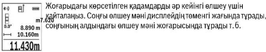
Yazikci3 enuey
Y3dkci3 enweyde enwey KypalbH HBicaHa XblXbI TYfa 6onaDb, OHda enwey KeNemi
waM. ap 0,5 cekyHd caBbH KaHapaDb. Mbicanb, Ka6bpFadaH KepeKti KaWbIKtbIKKa
eTyIH3 MymKiH, KaWbIKTBkTb ApdaHbIM Kepyre 6onaDb.
Y3iKci3 enweydi TaHaHbI3.
Ia3ep cayncin Kocy yuih 2 [ ] anwe npheine Kbcka 6acbHb13.
OJy KpaBnKpekTi KaBbIKbIK DnCnIeHIN TEmHRI 6JIirHde KepcTeIRHeW
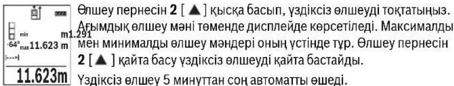

AydanhdbI enuey
AyaHdbI eHweydi TaHdaHb3.
CocbH y3bHbIK neh eHH dneKTI Tpye y3bHbIKbI eHweHde enWeH3. Eki 0nwey apacbHa naep cayneci kocynbl 6oNbl Kaanbl. OJwHeHt H KaWbIKbK aydaHbI eNwey KepcETKiWHe. XbInblbKTaHbl.
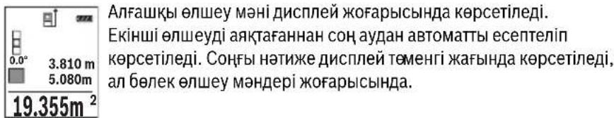
Koenni enwey
Kelem enweydi TaHdaHb3.
CocbH y3bHdbfBih, eHIN XaHe TepeHdiirn dne KTI Tpye y3bHdbkTbI enWeHde 0IweH3. Yw eIwey apacbHa naep cayneci kocynb6onbl Kaanbl. OIweHetIH KaawbIKTBK KelemH eIwey KepcETkiuHne

1609 92A 1RR| (26.11.15) Bosch Power Tools


Ka3akwa 365
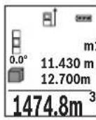
AnfaaKbI eHwey MHI dncnne JxofapbcbHda Kepcetinei.
Yuihwi enweydi aKaTaFaHHaCOH KeNemi ABTomaTbI ecenTein
Kepcetinei.CoHbHnKe Dnncne TEmeHr XaFbIHda Kepcetinei, an 6enek enwey mHepei kofapbcihda.
KaHama KaWbIKTbIKbIT eNwey
KaHama KaBbIKbIKbIeNlwey yIiH yIu eNlwey cyHKunrcbI 6ap, onap apKbIbI typni KaBbIKbIKTapdbI eNlwey MymkIH.
KaHaMa KaBbIKbIKbIe OJney Ceyne XOnbIHda Keepri Typyi HeMece HbicaHbik aMak KaTapaBH Jep petiHde KonKetIMdi bOImaybI ce6ebiHeh Tikeen eJWeHBeTIH KaBbIKbIKTapdbI OJneyre Kb3Met etei. OcbI OJney aNiciH TeK TIK 6aftTa naDanaHy MymkIn. KeJeHEn BaftTaBly ayItky OJney KATENIKTepiHe anbln keJIi.
Eckenptne: KaHaMa KaBbIKTbIKTb 0JIwey TKeNe KaBbIKTbIKTb 0JIweyDeH dIaC3 60aIbI. NaIaIaHy KaFdaiBaHa 6aIIaHbICTb peTte 0Jwey Kateniri TKeNe KaBbIKTbIKTb 0JIwey KatenirHeh YIkeH 60aIbI. OJwey dAnirih KaKcapTy ywiH TaFaHDbI NaIaIaHydbI YcHbAmbl3 (Ka6dbIKTap).
Enweynep apacbHda na3ep cayneci kocybl bobnkanaabi.
a) KaHama 6nIKtIKT eNwey (B cypetih KapaHb13)
KaHama 6nIKtIeIeIeYdi TaHaHaB13.
Onwey KypanbTeMeHri OJwey HkyTecimEn 6ip 6nIKTKe 6onybHa Ke3 KeKti3iH3.
OJwey KypanbH Hei3rI Ka3bIKTBkTAH aHaNDbIPbIN KaWbIKTBkTB1 "1" Y3bIHbIKTB1
OJweHdEe OJWeH3 (DncnneJe Kbl3bn Cbl3bK petHKePcetinreH).
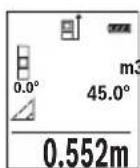
Ouweyai aKaTaHaHnCoh KepeKTI " ^ 其 KaBbIKbIH HOnwey HAtnxeci HATNXeep KonfbiHda e Kepcetinei.1" KaBbIKbIFbIHbH eNwey Kcnemdepi Meh 6pyblu "a" onwey Kcnemdepi XonafbiHda Tp d.
b) Koc kahama 6niktikti eunwey (C cypetih kapahti3)
OJUey KypaIbIOHbIH BepTnKaIdbI DeHReiHDe XaTaTBH 6apNbIK KaBbIKTBkTApDbI XaHaMa eNJUeyIMyMKIH.
KocbIn, JkaHama 6nKiTikTe enIeuyi TaHaDbI3.
"1"MeH"2"KaWbIKbIKTapDbI y3bIHDbIKbI eIWeReHdE ocbI dneKeTc eIWeH3.


366|Kaazakwa
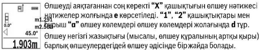
c)KaHama y3bHdbIKtbl enuwey (D cypeTih KapaHb13)
XaHaMa y3bIHbIKTbeIeWeyI TaHaHbI3.
Onwey Kypanbl i3dienren enwey Hkyteimeh 6ip 6nIKTKe 6onybHa Ke3 XeTki3iH3.
Owey Kypanbl Er3iri Ka3bIKTBkTAH aHaNDbipIN KaWbIKTBkTbI Y3blHdbIKTbI
enwereHde enweh3 "1".
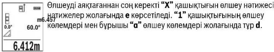

Ka6bipra aydaHbIH enwey (Ecypetin kapaHbI3)
Ka6bipra aydaHbH enuwe bipehewe kannb6niktikti 6enek aydaHapdbH KocbHdbicbH ecenTeyre Kb3MeT eTei.
CypeTeri Mbicanla 6ipHewe 6nKTIi H 6ipDei 6ipak typni Y3bIHdbIKtbl L Ka6bpFanapdbH xannb aydaHb ecentenei.
Ka6bipyaaydaHbH eniweydi TaHaHbI3.
6bnme 6nikirin H y3bHdbKtB tbnwehen eIwnHei. OJney MHI XOFapfbl nIwey MHI JONaftbHa Kpcetinei. Naep Kocynl kanaDbI.
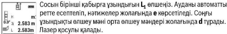
3.336m² CocbH ekihui Ka6bipFa y3bHdbfBih L2eHwei3. Heuey MHi XONaFbHnda d KepcTeinreH eHwey MHi y3bHdbkKa L KocbJnabbl.
Eki y3bHdbik (opTa enuey MAni KOnaftbHa d) KepeTinre H caTanFaH 6nKtike H Ke6eHTinei. KaNb aydaH mHi HATnKeIep KOnaftbHa d e KepeTinei.
Ke3 KeIreH 6aCkA y3bHdbIKTapDbLx eNwey MymKiH, Onap aBTOMaTbI peTte KocblbnBn 6nIKtke H ke6eTInei.
Dypbc aydaHbI ecenTey anfbIwapTb 6ipihwi eHneHReh y3bHdbK (Mbicana 6eNMe 6niktiri H) 6apblk 6eneK aydaHdp yinH 6ipdeB onybl.


Kaazakwa 367
Benriney yhKunacbl (F cypetin KapaHb3)
Tpaccnpey fHKnncbI aHbIKtanFaH y3bIHbIKTbI (KaHbIKTbI) oJneDi. OcbI y3bIHbIKTapdbI 6eTepre Kowipin, MaTePnAnDbI 6ipDei eJWemdk 6enikTepre Kecy Hemece KapKacTBk RnckapToH Ka6bpFanapDbI opHaTy MymKin. MHHMaNdbI peTteJIH y3bIHbIK0,1, Man MaKcImaNdbI y3bIHdbIK 50 6oJaDbI M.
TpaccnpneyyHKnrcbH TaHaHb3.
KepeKti y3bHdbkTb peTHei3. KocbIMwa 7 [Func] nepheciMeH Tnicti caH/kaNdi TaHdAn MAni 3 [+] nepheciMeH Hemece 8 [-] nepheciMeH e3reptiH3.
TpaccnpneyyHKcncbH2[ ]eIwey nepheciH 6acbln 6actay HkyTecineH kai aJIbICTaHbI3.
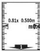
Onwey KpaIbI y3dikci 6actay HkytcicHe deinH KaBkTBkTBe IJWei. OHda aHbIKtaHaH y3bIHDbIKTap MeH aFBIMdk eNwEMeDep KepCetinei. TeMeHri Hemece KOFapFbl KepcETKI KaBihDan JAtKaH Hemece COHfbl Benrire deinH KbICKa KaBkTBkTB KepeTei.
Eckptne: Y3dkci3 eJweye 4 nepheciH 6acbin, eJWeHReH MAnDi de 6enrineHRe H y3bHbik petiHde 6enriny MyMKH.
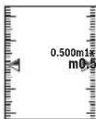
Con JkaTbik fakTop 6enrineHReH y3bHdbk Hewe pet XetirnreHIn Kepcetei. KacbI KepcTeKInep Dncnnepe 6enriney MaKcatbHa a3bHdbkKa KeTydi Kepcetei.
Ken6eydi enwey/CaHdbik ypoBeHb
Ehicti onweydi/caHdbIK DeHreNdi TaHaDbI3.
Thneuey KypaIbI eKi KyI apacbIHda 03reptedi.
CaHdbIK DeHRe HbicaHHbH, Ropn3oHTaJIbI HeMece BepTKaJIbI 6aftTanybHa KbImeTeTei (MbicaJIbI, KIP JyfbIIM MaUNHa, CyblTkbiW XHe T.6.).
Erep 3^ ehici apTbIn KeTce, OHda DnCnnneJe Wap Kbl3bl TcTe KaHaabbl.

Kenbeyi eIwey KTeepinicti HeMece enicti (MbicaIb, caTb, TaHbIHTapbl, kHa3dapbl kipictipyde, Ky6bpnapbl canyaT.6.) eIweyRe Kbi3Met etedi.
KoN6eYdi OJwey yWIn Heri3ri Jx3bIKTBk peTihDe OJwey KypaIbIHbIH con KaFbI 60ana. OJwey aicHne Kepcetki WbInbIKTa cJwey KypaIbI JaaHbHa KeN KncaTbINFaH 60ana.


368|Kaazakwa
CaKtay yHKnuaIapbl
Op opbHdAnFaH eIeuydiH MHI MeH COHfBI HtNkeci ABTOMaTbI CaKaTaIaIbI.
CaKtanafanMmKepcTeKiWi
MaKcHMaIbI 30 MAnep (eNwey MaHepi Hemece coHfbi HtHXenep) WAKbipy MYMKIH.
CaKaydyHKUINcBih TaHdaHbI3.
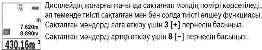
KaTAMHOK60ncnneTeMeHriXaFbIHda"0.000"anXofapfblXaFbIHda"0" Kepcetilei.
EHcoHfbmHaJxad1OpbHdaTypaDb,anehcoHfbicb30opbHda(30caKtaIraH MAnepi konjketimdi bOraHa).KeHHri mHaI caKaTaHaJa KaTApaBIM eEecki MAn KOJIbIaDbI.
CaKtfbIiTaftbHbI eWipy
KadMa3MyhbiH XOIO yuH 7 [Func] nepheciH taHdAn caKTay cyHKUcBIn TaHaHbI3. Cocbin Kocy-owipy nepheciH 5 [ ] KepceTINReH MAnDi XOIO yuH 6acbl3.
4 nepheimekocy-ewipy nepheciH 5 [ ] 6ipdei bacy apkblb6apblk kda TpyfAH MAndep KOnblaBl.
MaHepdi kocy/any
OJnwey mAnepi Hemece coHfbi HtNKepepi Kocy Hemece any MymKIN.
MaHnepepiKocy
TeMeHnDiI MbCaIIa aydHaapDkoCy CnIaTaNFaH:
AydaHdbi"AyaHdbIeJnwey"6bnimi 6oBihua ecnteh3,364 6etin KapaHb3.
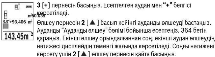

Ka3akwa 369
Eckptne: Y3bIhDbIKTbI OJIweyde COHfBI HAnke Depey Kepctinei.
KocyaHn 7 [Func] nepheciH 6acbHb3.
Məndepdi any
MAnepdi any yuiH 8 [-] nepheciH 6acbHb3. KeiHri apekeTep "MAnepdi Kocy" aDiciHe YKcac.
OHTHKeNepIN KOIO
Kocy-ewipy nephecin 5 [c] Kabicka bacbin bapnbik eunwey fynkunapbHda coHfbl ecentenre H mHepdi koo myMKIN. Kocy-ewipy nepheci 5 [c] biphepe pet bacInbn enwey mHepi kepi pTTiniknen kOoiBnaBl.
Onwey bipnirin anmactbipy
Her3iri npametpiHne "m" (MeTp) eIwey 6ipniri 60anabl.
Oney KypaJIbH KOcbIbI3.
7 [Func] nephecin 6acbin yctan, "Herizir mHep" m3ipine etiH3. "ft/m" TaHaHb3.
3[+]Hemece8[-]nepheci6acbIn,enwem6ipnirihaybcTbIbIbI3.
M3ip TapMaftBHaH WbIfy yWih 5 [ Kocy-ewipy nepheciH 6acbHb3. Onwey KypaBn HwipyeH coT TaHdaFaH npaMeTp caKaTaAaBl.
Bluetooth® uHTepfeuci
Baca Kypanapra Depek TacbImanay
Ounwey KypanbluethoMoynimEn Ka6bikTaNfah, on paNtoExnka apKbIbn
Benrini Moibdki Ka6binyuBkypanapra Bluetooth yAusbIApKbInb
depeKeTpTiTacbImaayFa MymKinhik Bepee (MbicancMapToH, nnaHweT).
Bluetooth® 6aIIaHbIcBi yIiH tanan etinTeIH KJyHenIK aIbIwapTTap TypaJI Bosch INHTepHET caTbIHDa TEmeHderi MeKeHkaJaTa6acb3: www.bosch-pt.de
Baca mAnimetTepDi Bosch eHIM Be6caHbHa Ta6acb3, QR KoDbIH KapaHb13, 86etInHe.
Bluetooth® apKbInbI DepeKTePdi TacBImaNlaya Mo6nNbbl Ka6blnybl KypalmeH eJneuy Kypanbl apacbHda yaKbTTbK aKbIPbHdaNybl naJa 6oJaNbl. Ce6e6i eKi KypaldbH, 6ip-6ipine KaBbIKbFbHa HeMece oJNeuy HbicaHbHa 6onybl MymkH.

370|Kaazakwa
Moibnbblkypanfa Bluetooth yawbfbapkbnbdepeKTePdi TacbMaIaydbi 6encendety
Bluetooth® nHTepfchciH 6encHeTeY ywiH eUwe KypaBbHbH Bluetooth® TYmeciH 6
6acbl3. Bluetooth® cnHaBbH 6encHeTeY ywiH Bluetooth® nepheciH 6 Hemece
3 [+] nepheciH 6acbl3. MoNbIbI bKypaBbHb3da Bluetooth® yIbIFbHbH
6encHdi 6onybH KaMTaMaCbI3 etIH3.
MobnIbIbI KpyanDbH cyHKunnaIapBIn KeHeHTy XeHe DepeKTePdi eHdeYdi OHTaIIaNDbIpy ywiH apHaNbi Bosch 6aFapnAmapBb (Apps) 6ap. OHb Ka6bldayu bI Kpyanfa baIaNbIcTb TnICTi dyKeHepDe catbl anyFa bonaBl.
Bosch 6aIapnamapbH bactaydah coH mobnbdi KypanmeH enwey KypabI apacbHa6aIIaHbc JacaIaNbI. BipHeSe 6encehiEneWey KypabI Ta6bnca, KepeKti eIwey KypalbH cepnblk Hemipi Herizihde TaHdaH3.
BaIaHbIC Kyi MeH 6eNceHdi BaIaHbIC (a) eIwey KypalbIHbH, Kyi naHeniHde h KepcTeJIeJI.
Bluetooth® yawbifbin ewipy
Bluetooth® 6aɪnəhɪcɪbɪn Ṭɪpɪy yɪn iN Bluetooth® nepheci n 6 bɑsɪhɪz. Bluetooth®
Cɪrɪnəhɪn Ṭɪpɪy yɪn iN Bluetooth® nepheci n 6 Hemece 8 [-] nepheci n kaɪt a 6acɪhɪz.
Hemece Εηιδeɪy Kɪpʌnɪbɪn Ṭɪpɪpɪzɪz.
Painanany HucKaynapbi
BacaMaIImeTepDi Bosch eHIM Be6caaTbIHda Ta6acbl3, QR KoDbIH KapaHb13,86etihde.
Θηωeу KypaIbI paIIO yAusbIbIMeH kA6DbIkTaNfA.KeprinIKTI naIdaIaIHy wekTeynepiH,MbicaObl ywakTapda HeMece emxAHaIapda,caKTay KepeK.
Kannbl Hcckaynbikrap
Ka6bIyay HnH3acbl 14 MeH na3ep 15 mbfBcBIn eHneyeJe Ka6yfa 60MaJnbI.
OJnwe KypaIbI eJnweyde K03fanybIMymKIn EmeC. CoI yuH enwey KypaIbIH typaKtB1 TipeK aHaMaFbHa KOHybIbI3.
Onwey aHaMaFbHa ocepne
OaMafbI KApbIKTbIKKaFaDaHbIMeH HbICaHbIKaMaKTbIH KaTapy KacneTTepiHe bainhictb. KaTb6eJeaKpBkTa na3ep cayncih JkaKcbi KepiHy i yinna3ep Kepy Ke3inDipiri 18 (KepeK-KapaKap) MeH na3ep HbICaHbIK TaKTaHbI 17 (KepeK- KapaKap) naDanaHbIN HbICaHbIK aMaKTbI eWipiHi3.


Kaazakwa 371
Oney HtHexecine acep ety
ФИЗКАЛБИСЕРЕПЕТYPПIбETTEPDERIENWEYNEPДурICopbHdAIMaybIMyMKIN. MyHDAI6ETTEPREKATAbl:
- Mənɪdɪp 6eɪTep (Mbɪcʌbɪ Ṭɪnɪkær, cy),
- ⅢaftbIbIcTaBH6eTTep (MbIcAlbIXbINTbIpaFaH MetaI, ΕHek),
- 6opKbIJaK 6eTTeP (MbIcAbl, OkWaynay MaTepeNanapbl),
KypblbIMdbIKBeTep (Mbicanbl,cbnak,TabnFtac).
Ocb6eTeppe na3ep HbicaHbIK TaKaTaHbI 17 (ka6dbik) naJaandaHaHbIbI3.
Kate onweynepi Kncbik Ke3deIreH HacaHdbik aMakTapda da opbHday MymKIn. TemnepaTypacbi ap Typni aya Ka6aTapbl HeMece Kon6ey waFbInbcynap onwey Hntxkeihe Kepi acep etyi MymKIn.
IaikTeKcepy MeH Kc6eyi enweyki KaH6pney (G cypetin KapaHb3)
Kynenik type Kən6eyi onwey dənirin TekcepiH. Ohbi kepi onwey apkblbOpbHay Mymkn. Onwey KypanbH yctenre KoBIn Kən6eydi KIweH3. Onwey KypanbH 180° bypan Kən6eydi KaTAt eonweH3. Kepcetiren caHdbH, aHbipMaMbIfbMakc. 0,3° 6onybKepeK.
Ynken aybtkynapda eIney KypanbH KaTaNknpny KepeK. On ywiH CAL eipin3. Dncnnneri HcckaynapdbOpbHdAbl3.
YlKeH TempeAtypa aybicyiHaH HeMece cokkblapdaH coH dAnIKTi TeKcepyi XHe KepeK 6oNca eIwey KpaBih KaIIbepyei YcbHbAmbl3. TempeAtypa aybicyiHaH coH KaIIbepyeH anDbH eIwey KpaBih TempeatypcbH dypbictayb kepeK.
OBJ_BUCH-2450-004.book Page 373 Thursday, November 26, 2015 10:46 AM

Kaazakwa 373

Ka3aKcTah
JLIC“Po6epT BOW
3Jektp KypanapbHa KaBImeKepcTeOpTaBIfbI
AImaTbI kanaCbI
Ka3aKCTAH
050050
PaiBIM6ek DaHFBiBi
KOMMyHaIbHaI KwueciH,6ypbIbI,169/1
Ten.: +7 (727) 232 37 07
ΦaKc: +7 (727) 2330787
E-Mail: info.powertools.ka@bosch.com
Pecm caTb: www.bosch.kz; www.bosch-pt.kz
Kadeere kapaty
OJy KpaHbIH, OHbIHKaBbIKapbI MeH KaTAmcBih KopWHaH opTaHbI KopFaTbIH KaTe JapAty opHbHa TaNCbpy KaKeT.
Ouwe KypaapanapbH XHe aKKyMyrTopnapbl/6aTapeanapbl y KoKbIcblHa TaCTaMaHbI
Tek KaHa EO enepi ywiH:
Eypona 2012/19/EU epexeci 6oynHwa kapaMcb3 enwey Kpaanapblx He Eypona 2006/66/EC epexeci 6oynHwa 3aKbIMdaIHaH HeMece ecki aKKymyIaTOp/baTapeaIap 6eNeK XHHaJIbI, KeJeTe JkaPaTbIybl KaKeT.
TexHnKaIbIe3repicTepeHri3y KyKbIbI caKtanadbl.
374 Romana
Romána
Laser Radiation Do not stare into beam Class 2 laser product
Executive Vice President
Head of Product Certification
Engineering
PT/ETM9

法式1. i.v. h · m .
Robert Bosch GmbH, Power Tools Division
70764 Leinfelden-Echterdingen, GERMANY
Leinfelden, 10.11.2015
Elemente componente
Numerotarea componentelor illustrate se refera la schita de la pagina grafica.
1 Display
9 Capac compartment baterie
10 Dispositiv de blocare compartment baterie
11 Numar de série
12 Placuta de avertizare laser
13 File stativ 1/4"
14 Lentilä receptoare
15 lesire radiatie laser
Tel. service scule electrice: (021) 4057540
Fax: (021) 4057566
E-Mail: infoBSC@ro.bosch.com
Tel. consultanta clienti: (021) 4057500
Fax: (021) 2331313
E-Mail: infoBSC@ro.bosch.com
www.bosch-romania.ro

Eliminare
Aparatele de masura, accesoriile si ambalajele trebuie directionate catre o statie de revalorificare ecologica.
Nu arunca'i aparatele de māsura Ši acumulatorii/bateriile in gunoiul menajer!
Laser Radiation Do not stare into beam Class 2 laser product
Ako TeKCTbT ha npedynpeHnHaTa Ta6eNka He e Ha Baun e3NK, npedn nycKaHe B EKCnnoataa 3anene T Bbpxy Ta6eNkata BKnueHn BOKmneKTOBkata CTKeP c TeKT Ha Baun e3NK.

He hacoBaIte Na3epHnIbIy KbM Xopa I KBNOTN IN BHNMaBaIte Da He NOrNeHETe HEnOcpeDCTBeHO Cpeu Na3epHnIbUHn Cpeu HerOBO OTPaXeHne. TaKa MoKeTe Da 3acJeNITe Xopa, Da npChHInTe TpyoBn 3JIOJNYKn Hn Da npEtn3BnKaTe yBpeKda-He Ha OHTe.
Ako na3epHHaTbHnADHe BOHTe, Hn 3aTBOpTe Bb3MOxHO Ha-6bp30 nOTdpbHHe TnaBATA cH OT na3epHHaTb4.
He n3BbpuBaIte n3MeHEnHa no Ia3epHoTo o6OpyDbaHe.
He n3no3BaIte ouHnata 3a Ha6nOdaBaHe Ha na3epnHa bKaTO npEpa3Ha pa6oTHn ouHna. Teu ouHn cnyKAT 3a no-do6poTo Ha6nOdaBaHe Ha na3epnHa bU, Te He npEpa3BaT OT Hero.


BbIgapckn | 393
He n3no3BaTe Ounlata 3a H6nIOdaBaHe Ha na3epHHa b4 KaTO cHbHuEBn OoHna Hn DOkato yuctBaTe B ynnHOTOBHXeHne. Ounlata 3a H6nIOdaBaHe Ha na3epHHa b4 He oCnIpyraBt 3aunTa OT yIITpaBNOJeTOBHTb4uN OrpaHuaBAt Bb3npHaMeHa NaCBetOBTe.
Дonyckaite H3MepBaTeHnHrT ypeДа 6bde peMoHTnpaH caMo ot KBaHnФuHa nTexHHuCaMo cH3NoI3BaHe HaOpHnHaHnPe3epBn qactn. CToBa ce rapaTHnpa 3ana3BaHTo HaФyHKuHrTe, oChrypRaUng 6e3oNaCHocTtHa H3MepBaTeHnYpeD.
He octabayte dea 6e3 npk hnd3op da pa6otc n3mepBaTeHHy ypei. Mo- raT HeBONHO da 3acnenT dpyn xopa.
He pa6oTeTe C MepBaTeHnH ypeB CpeDa C NOBnueHa ONaCHOCT OT EKcNIO3HH, B KOrTO HMa NecHO3aNaHMM TeuHOCTH, Ra3OBe HnN IpaxOBE. B n3-MepBaTeHnH ypeD MoT Da Bb3HnKHa T NCKPN, KOnTO Da Bb3PiMaEHr T Ipaxa HnN napHTe.
BHHMaHHe!PnIOn3BaHToHa H3MepBaTeHHN HNCTpyMeHc BluTooth e Bb3MOxHo CmUaBaHTo Ha pa6oTaT aHa DpyrHu yCtpoHCTBa H cbOpBXeHHa, camOJeTH N MeHUnHckn anapatn (HaNP. CbpeuHN CTMylnaTOpn, CnyXOBn anapatn).CbTO taka He MoKe Da ce N3KNIOH EBEHTyAnHO BPeDHO BnHnHe Bbpxy Xopa H XNBOTn. He N3NoJ3BaHTe ENEKTPoHHCTpyMeHTa C BKIOueH Bluetooth B 6n30ct Do MeHUnHckn anapatn, 6EH3HHOCtAHuHN, XHMNUHn CbopBXeHHa, B 3OHN C NOBUnHeA ONACHOCT OT EKCNI03HN H B 6n30ct Do B3pHBooNacn MaTePhann. He N3NoJ3BaHTe ENEKTPoHHCTpyMeHTa C BKIOueH Bluetooth B camonET. H36raBai Te npOdbXkntenHata pa6oTa B HenocpeDCTBeHa 6n30ct Do TANOTO.
TepMHbT Bluetooth, KaKTo H cHMBONHTe (Norata) ca perHcTpnpaHn TbproBCKn MapKn H co6ctBeHocT ha Bluetooth SIG, Inc. BcKaO non3BaHe Ha Te3H TepMH H cHMBONr Robert Bosch GmbH e cbrNaCHO nHcH3.
OncanHe Ha npOyKta N Bb3MOxHocHTe My
MOn,OTBOpTe pa3rBaUaTa ce CtpaHnca c Hpynte Ha N3MePBeJIHHy ypeH, DOKaTO YeTeTe pbKOBoCTBOTo, J OCTaBeTe OTBopeHa.
PpeHa3HaueHne Ha ypeDa
I3MepBaTeHnHTypee npeHa3HaueH 3a I3MepBaHe Ha pa3CTOHH,DbJKNHH, BnCOuHH, HAKLOHn 3a I3UncBbAHe Ha IIOUIN O6emN.
Pe3yntaHTe OT n3MepBaHTo MoT a 6bDat npedaen c Bluetooth® Ha npyrn ypei.
Bosch Power Tools 1609 92A 1RR| (26.11.15)


394|BbIrapckn
TexHHueckn daHHN
| цирoveл лазерен урета язмервае на glm 50С разстория | GLM 50 C |
| Каталожен Homep | 3601K72C... |
| Диапазон на язmerвае (объknовeto) | 0,05-50 m A) |
| Диапазон на язmerвае (неблично, несято- приятын уменья) | 20 m B) |
| Точность на язmerвае (obъknовeto) | ±1,5 mm A) |
| Точность на язmerвае (obъknовeto, небличтори уменья) | ±3,0mmB) |
| Минимално делени на скалata 0,1mm | |
| Иndириктын язmerвае на разсторияи пьбени | |
| Диапазон на язmerвае | 0°-360°(4x90°) |
| IЗmersване на полons | |
| Диапазон на язmerвае | 0°-360°(4x90°) |
| Точность на язmerвае (obъknовeto) | ±0,2(C)/D)/I) |
| Минимално делени на скалata 0,1° | |
| ОBSTIP napаметри | |
| РавOTEN Temператугий язалазон | -10°C...+45°C |
| Temператугий язалазон за съхсанье | -20°C...+70°C |
| OTHOCITIELNA Влажноct на Вьздуна, Марс. | 90% |
| Клас пазер | 2 |
| Тил пазер | 635 nm, <1 mW |
| Диаметын язgerпуня льч (при 25°C), п riбл. - на разсторияе 10 m | 9 mm D) |
| - на разсторияе 50 m | 45 mm D) |
| АВТOMATЧИЗ NO I3KЛЮЧВАЕ с Vide п riбл. - пазер | 20 s |
| - ИзMERВATELEN у畴 (бez язmerвае) | 5 min H) |
| Маса съласно EPTA-Procedure 01:2014 | 0,10 kg |
| Габаритни размери | 106x45x24m |
| Вид зашита | IP 54 (эаштейн среши чь и ВODHI Пьски)F) |
1609 92A 1RR| (26.11.15) Bosch Power Tools


BbIrapckn|395
OBJ_BUCH-2450-004.book Page 396 Thursday, November 26, 2015 10:46 AM


396 |Быларскн
Texnuecka doKymeHTaun npn:
Robert Bosch GmbH, PT/ETM9,
70764 Leinfelden-Echterdingen, GERMANY
Henk Becker
Helmut Heinzelmann
Executive Vice President
Head of Product Certification
Engineering
PT/ETM9

S APQ = S AQC + S_ PPD
Robert Bosch GmbH, Power Tools Division
70764 Leinfelden-Echterdingen, GERMANY
Leinfelden, 10.11.2015
H306pa3eHH enemeHTn
HomepupaHTo Ha enemEnTte ce OTHa Do n3o6paXeHHeTo Ha n3MepBaTeHNHa ypeHa CTpaHnCtA Tc Hpynte.
1Dncnnne
2 ByToH 3a N3MePBAHe[ ]
3 Bytoh 3a cbbnpaHe ([+]
4 BytoHn36Op Ha otnpaBHa paBHHa
5IyckOBnpeKbCBaY[
6 ByToH Bluetooth
7ФункцюнаньуToH[Func]
8 ByToH 3a n3BaJkaJaHe[-]
9 Kanak Ha THe3doTo 3a 6aTeepn
10 ByToH 3a 3acToOpBaHe Ha KaNaKa Ha rHe3doTo 3a 6aTePm
11 CepneH Homep
12 PpeynpeHtEnHa Ta6eKa 3a Na3epnna bU
13 Pe36OBN OTBOP 1/4"3aCTATHB
14Приемашиа.
15 OTbOp 3a na3epnna bcu
16 PpeDn3Ha YaHtA
17 Ia3epHa MepntenHa IInoya*
18 OuHa 3a Ha6IIOdaBaHe Ha Ia3ePnIbY
19 CtaTHB
*H3o6pa3eHHTe Ha 0hrypHTE HnONHCANB B pKOBODCTBTO 3a EKCnnoataaHOnbHNtEN HnpNCnocobHeH He Ca BKIOUeHH B OKOMNIKEKTOBkata.
1609 92A 1RR| (26.11.15) Bosch Power Tools


BbIrapckn | 397
TokaBahn enemEn (n360p)
a CbCToHHe Ha Bluetooth®

Bluetooth®akTNbHaH, HMaMa 3rpaDeHa Bpb3ka

Bluetooth®akTnBpaH, n3rpaJaHa Bp3Ka
b OTnpaBHa paBHnHa 3a H3MepeBaHeTo
C INHdkatop 3a 6aTepehnaTa
D PeIOBE 3a H3MepeHInTe CToHOCHTN
e Pe3a pe3yntata
f PekmHa pa6oTa
gIone3a bIbI NaHaKaHIOHa
h CtaTychaJeHTa
I OCHOBHNHaCToPoiKn
Mоntиранe
BnHaHcMeHnTe BcNcKb6aTePHn,peCn.akymyNaToPnHe 6aTePHn eHOBpeMeHHo.
H3noJ3BaIe cAmo 6aTePHn HnAkymyNaToPn 6aTePHn Ha eINn IpOn3BOJntEN C
eHaKaB KaNaUHTe.
Korato Hama da H3noJ3BaTe H3MepBaTeHnHa ypei npoDbIxxHTenHO BpeMe, H3BaxdaTe 6aTePHnte, pecn. akymyNatOpHnte 6aTeHN. Ppi npoDbIxxHTenHo cxbxaHbAbe BypeDa 6aTeHNte n akymyNatOpHnte 6aTeHN MoTa Da KopoDnpat N da ce camopazd.
Bosch Power Tools 1609 92A 1RR| (26.11.15)


Pa6ota c ypeda
Pyskahe Beknloaataua
He octabnte ypea BkIOueH 6e3 Ha3Op; cneKATO pRKnIOUHTe pa6Ota, ro H3KIOUbaTe. npyI nIua Moar Ta 6bDat 3acneHn OT na3epHna b4.
IpeNa3BaIte H3MepBaTeHnI np6Op OT OBnaXHBAHe I dHpeKTHO nonaDaHe Ha CbHcEbnIbU.
He n3naraTe H3mepBaTeHnnu ypeHaekCTpeMHn TemnepaTyPi Hnpe3Kn TemnepaTyPhn npomeHn. Hanp. He ro octabTne npodbNKeTHno BpeMe BAToMo6nI. Ppi rOleMn TemnepaTyPhn pa3NNKn OCTabReNe H3mepBaTeHHrYpeDn da ce temnpina, ppeDa ro BKIOUHTe. Ppi ekCTpeMHn TemnepaTyPi HnroJeMn TemnepaTyPhn pa3NNKn TOHOCCTTa Ha H3mepBaTeHHn upe MoKe Da Ce BNOuN.
H36BaIe CnHH yIapn Bbpy H3MepBaTeHNy ypeI. CneI cHNI BbHNI MExaHnHn Bb3dEiCTBna Tp8Ba Da H3BbPunTe npOBepKa Ha ToUHOCTTa Ha H3-MepBaTeHNy ypeI, IpEi Da npOdbJNKeT da ro H3NON3Be (BxKTe „IpOBepKa Ha ToUHOCTTa Ha H3MepBaHe Ha IbJnxHi, cTpaHnca 408).
BknIOuBaHe n H3KnIOUBaHe
- 3a BKNIOUBAHe Ha N3MepBaTeHnHa ypei HaJIa3epa HaTnChTe KpaTKoTpauHO 6yTOHa 3a N3MepBaHe 2 [▲].
3a BKnIOuBaHe Ha n3MepBaTeHnIypeI 6e3 Ia3epa HATncHeTe KpaTkoTpaHNo nyCKOBnI pKeKbcBaU 5 [0]
He hacoubaTe na3epHnaIbKbM Xopa HnN XNBOTHN; He rneJaTe cpeuy na- 3epHnaIbU, cbso n OT rOJMAo pa3CTOHHe.
3a n3KIOUbaHe Ha n3MepBaTeHnHa ypeI HaTnCHeTe 3aApbXTe NyCKOBn IpeKbcBau5 [
PnH3KIOUcBaHe Ha H3MepBaTeIHHy ypeI HAmpaIte Ce B NaMeTTa cToHocTH N HAcTPOIKTE ce 3ana3BAT.
N3MepBaHe
CneB KIOUOBAHe N3MepBaTeHnIypeD Ce HAMnpa B pexm 3a N3MepBaHe Ha IbJnnn. 3a npyaФyHKunHa N3MepBaHe HATNCheTe 6yToHa 7 [Func].N36peTe JeNaHaTaФyHKUnHa 3a N3MepBaHe c 6yToHa 3[+] nIn 6yToHa 8[-] (BnXte,PeKmHa N3MepBaHe",CTpaHnca 400).AKTNBnPaTcФyHKUnTa 3a N3MepBaHe c 6yToHa
7 [Func] mnnC 6yToHa 3a n3MepBaHe 2 [▲].
CleB BkIIOUyBaHe 3a OTnpaBHa paBHnHa npH N3MepBaHnTa ce yCTaHOBBA 3aHnPa b6 Ha n3MepBaTeJIHHy ypeJ. 3a CmHa Ha OTnpaBHata paBHnHa BHXTe, N3bOp Ha OTpabHa paBHnHa", ctpaHnca 399.


BbIgapckn | 399
IOnpeTe H3MepBaTeHnYypeD IO XeHaHaTa HaaJIHa TOUka 3a H3MepBaHeTo (HaNP. cTeHa).
YnbTbaHe: Ako n3MePbATEHnHTypee e 6nBKnIOueH c NyCKOBn IpeKbCBaU 5 [c], HaTNCHeTe KpaTKoTpauHo 6byToHa 3a n3MePbAe 2 [▲], 3a da BKnIOuHTe na3epa.
3a CTapTnpaHe Ha n3MepBaHe HATNCHE Te KpaTKoTpaiHo 6yToHa 3a n3MepBaHe 2 [▲]. CneT OBa Na3ePHnT IbU Ce BkIIOuBa. 3a CneDbaIo n3MepBaHe NOBTOpeTe Ta3n npOeDypa.
He hacoubaTe na3epHnI NbKbM Xopa HnN XNBOTn; He rneJaTe cpeuy na- 3epHnI NbU, cbOIO NTOrnAMo pa3CToHHe.
YnbTbahe: N3MepeHaTa CToHocT O6NkHOBeHo Ce N08Ba CneI 0,5 s H He NO-KbCHO ot.4s. PpOdbJIxHtENHOCTa 3aBnCH OT pa3CToRHNeto, CBETNIHHNEcBOTHouHe N OtpKaTeHNHT CBOICTBa Ha CEneBaT NOBpXHOCT. CneI npNKIOUBAHe Ha N3MepBaHETo Na3ePHNATbU ce N3KIOUBA aBTOMaTHNO.
H36op ha otnpabha paBHHa (BnKTe qnr. A)
3a n3mepBaheTo moKTe Da n36paTe MeKdy Tpr pa3nUHn HaayanHn paBHnH:
- 3aHnna p6b Ha n3MepBaTeHHy ypei (HaNP. npn DoOpnpaHe Do CTeha),
- npednna p6b Ha n3MePbaTeHHypei (HaNP. npu n3MePbaHe ot pb6a Ha Maca),
- LcHbpbT Ha pe36ata 13 (Ha np. 3a H3MePbaHe OT cTaTnB).
3a H36op Ha HaayanHata TouKa HaTnChTe 6yToHa 4. C 6yToHa 3 [+] nnn 6yToHa 8 [-], nnn 6yToHa 4 n36epe Te JeknHaTa HaayanHa TouKa. BnHa n cIeBkInouBaHe 3a HaayanHa TouKa ce H36upa 3aDnHrT pb6 Ha H3MePbATEnHn ypeJ.
MeHIO ,OCHOBHH HacTpoIKN
3a Da BHe3eTe B MeHHTO, OCHOBHN HAcTPOKn" (i), 3aJpbXKe 6yToHa 7 [Func].
N36pepe cboTBeHaTa OUNHn CToHocTtA n.
3aДаиЗлесеOTMeHIOTo,OCHOBHnHaCTpoIKN“,HaTNCHeTe6yTOHa 3a BkIIOUBAHe n3KJIIOUBAHe5 [ ]
OcbetneHHe Ha dncnpea
OcbetneHnETo Ha nCnner e BkNoyeHo. C orneI npedna3BaHe Ha 6atepHnTe/aKyMyIaTopHnTe 6atepn, aKo B npodbJkeHne Ha np6n. 20 cekyHn He 6bJe HATnCHaT 6yToH, ocBtneHnETo Ha nCnner ce N3KnUoyBa.


400|Блгарский
PekmHaH3MepBaHe
I3mepBaHe Ha dblxHnHa
H36peTe H3MePbAHe Ha JbJxHa
3a BkIIOUbaHe Ha Ia3epHnI Ibu HaTnCHeTe KpaTKoTpaiHo 6yToHa 3a H3MePbAhe
2[▲]
3a n3MepBaHe HATNCHETe KpATKOTpaHNo 6yToHa 3a n3MepBaHe 2 [▲]. N3MepeHaTa CTOnHOCT Ce n3o6pa3raBA B DOJIHATA qACT Ha DnCINIE.
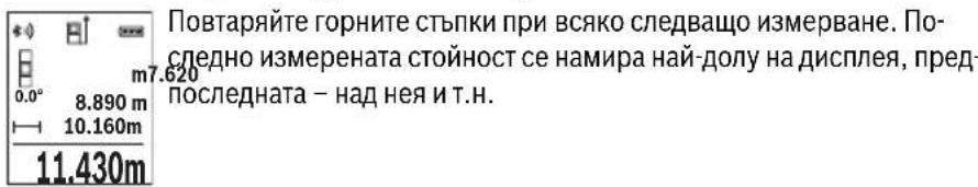
HenpebchaTo H3MepBaHe
Ipn HnpeKbchato H3MepBaHe H3MepBaTeHnHyt ypeJ moKe da 6bJe npMeCTBaH cnPMAO cIeEbaT aToKa, KaTO H3MepeHaT a CToHoc T ce aKtuaHn3npa BceKn O,5 s. HanpIMep MoKte Da ce OTdaneuHte OT cTeHa Ha XeHaHOT pa3cToHHe, TeKyUTo paoCToHHe CE Bxka HnpeKbchato.
I36peTe HnpeKbchaTo I3MepBaHe I
3a BkIIOUbaHe Ha Ia3epHnHa bY HATnCHTe KpaTKoTpaHb 6yToHa 3a H3MePbAe
2[▲]
Hacouete n3MepBaTeHNHa ypeD,doKaTo Ha dncnpee Ce n3o6pa3n cToHocTtHa JKeJhaHaTa IbJxKHa.
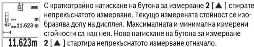
HenpeKbchatoI3MepBaHe ce I3KIOUyBa aBtOMaTHUHO cne5 min.

Былгарский | 401
H3mepBaHe Ha IIOou
N36pepeTe N3MePBAHe Ha nIooi
CneToBa H3MepTe NocNeIOBATEHNO HINPOUHHATA NdbJXHHATA, KaKTO Ce H3MepBat DblxHH. Mexdy DBete H3MepBAHNA3ePHNt bY He ce N3KnIOuBa. OTeCuKaT, KOrTO Tp6Ba Da 6bJe H3MepeHa, MfHa hCNMBOla 3a H3MepBaHe Ha PIOUI

Ibpbata n3Mepena cToHocT ce Noka3Ba B rOpHaTa qacT ha dncnne. Cnei npknIOuBaHe Ha BTOPOTo n3MepBaHe IIOUta ce n3cNcIba aB- TOMaTHUHO H CE NOKa3Ba.Ha-OTdOly Ha dncnpeCTOn pe3yNTaTbT,Ha Hero - cToHOCHTe OT OTeHNHTe n3MepBaHHa.
N3MepBaHe Ha 06em
H36peTe H3MePbaHe Ha o6eM
CneT OBa H3MepTe NocNeIOBATEHNO IHHPOUHNHa, IbIXHHaTn BHCOHNHaT, KaKTo ce H3MepBaT bIJKHH. MekNy TpIte H3MepBaHra Na3epHnRr IbY He Ce I3KIIouBa. OtceKaTa, KOrTO Tpr6Ba Da 6bJe H3MepeHa, MIRa Ha CnMBOna 3a H3MepBaHe Ha o6em
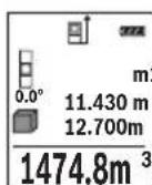
Ibpbata n3MepeHa cToHOCt Ce NOKa3Ba B TropHaT aCt Ha dncnne. CnepnKIOUbaHe Ha TpeTOTO n3MepBaHe o6embT ce n3uNCnBa aBTO-0.160 MaTHNO HcNOKa3Ba HA dncnne.Ha otDony Ha dncnneCTOn pe-3yNTaTbT, Hnd Hero - cToHOCHTe OT OTdennHe n3MepBaHHa.
HnDnpeKTHo H3MepBaHe Ha dbLnXnHa
Pa3noIarate c tpr fynkun 3a HnHne pKTHo n3mepBaHe Ha pa3CTOHN, KOITOMORaT da6bdat npinaHan B pa3nnuH cnTyauuN.
HnIpeKTHoTo H3MepBaHe Ha IbJxHa Cnyx 3a H3MepBaHe Ha pa3cTOnHn, KOHT He MoarTa bDat H3MepEn HnocpeDCTBeHo, Tb KaTO No NbTa Ha NbUa Hma npenrT CTBHe Hn Tb KaTO B KpaHaT a ToKa Hma Otpa3raBa a NobbpxHOt. To3m MeToH a H3MepBaHe MoKe Da bDe npInloKeH cAmO BBB BepTKaJIHO hAnpaBHeH. BcKO OT-KIOHeHne B XOpN3OHTaIIHO HApabLeHne BOIN Do yBENuYBaHe Ha rpeWKaTa B n3- MepBaHeTo.
YnbTbaHe: HndpeKTHOTO H3MepBaHe Ha pa3ctoHn e BnHa rno NO-HETOHO OT npeKTHOTO. CbflacHo npHHunHa ha pa6To rpeWKte npn H3MepBaHTo MOrat Da ca No-Tolemn OT Te3n pN DnpeKTHO H3MepBaHe. 3a NDo6pRaHe Ha ToHOCrTa Ha H3-MepBaHe PpeOpbUBaMe POJ3BaHETO Ha CTaTNB (He e BKIOueH BOKOMPNEKTOBkata).
MekdyOTdENHHTe H3MePBAHnIa3epHnIbUocTaBaBkIIOueH.
Bosch Power Tools 1609 92A 1RR| (26.11.15)


402|Быларсан
a) INHnpeKTHo H3MepBaHe Ha BncoUHa (BHXTe fHypA B)
N36peTe HnDInpeKTHo N3MepBaHe Ha BncoUHa
BHHMaBaIte H3MepBaTeHnHrT ypeI da e Ha eHa N Cb7a BnCOuHnC DOnHaTa TouKa Ha H3MepBaHe. CneToBa 3aBbPTeTe H3MepBaTeHnHry ypeI OKoN O HaayHaHaTa TOUka,1"(H3O6pa3eHa Ha nCnPJIe KaTO uePBeHa nnHn).
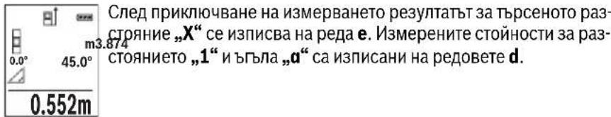
H36peTeIbOHO HINDIneKTHO H3MePBAHe Ha BnCOnHa
H3MepTe OTceKHTe,1" N,2"B Ta3n nocneIOBaTeHOCT, KaKTo 06NKHOBeHO H3MepBATE bJxHH.
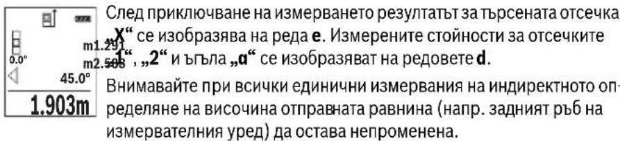
c) INHINPEKTHO H3MepBaHe HaIbIIXHa (BHXTeΦnR.D)
N36peTe HnHnpeKTHo N3MepBaHe Ha nblnxHa
BHHMaBaIte H3MepBaTeHnHrT ypeI da e Ha CbUaTa BnCOuHa, Ha KOrTo e TbPceHaTa KaHa ToUka Ha H3MepBaHeto. CneI TOBa 3aBbPte H3MepBaTeHnHry ypeI cnpMo OTpabHata paBHnHa H3MepeTe OtecKaTa ,1" , KaKTo ce H3MepBa DblJxHa.
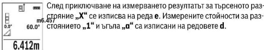


BbIgapckn | 403
Onpeenhe Ha nnouHa cTeHH (BnKTe fHr.E)
H3MepBaHeTo Ha nlouHa CTEN CnyxHa onpeJeHa o6ua nlou, cyMa OTnKoIko OTdJIHo H3MepeHn PLoU, Hmaun O6ua BncoUnHa.
Ha n3o6pa3eHnHa fHypata npimep Tpr6Ba da 6bde onpeedeHn o6uTa nIoU Ha HAKO KTeHn, KOTo IMaT eHa n Cbua BncoUHn H, Ho pa3nnuHn DblxHHn L.
N36peTe N3MepBaHe Ha IIOuTa Ha CTeHn
I3Mepete BnCOUHaTaH, KaKTo npu HOpMaJIHO I3MepBaHe HaNbJXHa. I3MepeHaTcToHOCt Ce NOKa3Ba Ha rOpHna peC pezYntaTne. Na3epbT ocTaba BKIOueH.
CneTOBaH3MepTe DbJxHHaTaLHa NpBpTaCTeHa.ПLOUta ce H3- m: 0.0°A 2.583m HNCJIBA aBTOMaTHUHO CE NOka3Ba Ha peDa 3a pe3yNTaT e. NocJeHaTa H3MepeHa DbJxHHa OCTaBa Ha DOJIHHa peD C pe3yNTaTn OT H3MepBaHe d. Na3epbT OCTaBa TBKIOUeyH.
3.336m² CnepToBaH3MepTeNbJKNHaTLaHaBTOpaTaCTeHa.NOKa3BaHaTaHa peJa d cToHocOTn3MepBaHeTo ce cyMnpa CdbJKNHaTaL.CymataHa DBeTe DbJKNHn (Noka3BaHa Ha cpeHnHa pe3a pe3yntaHd) ce yMHOkBa cbc 3anaMeTeHa Ta BnCOuHa H.Obuata cToHocHT Ha NIOUta Ce NOKa3Ba Ha peJa 3a pe3yntaTH e.
MoKeTe Da H3MepBaTe OSe HeorpaHueH 6poIbIXHHN Lx, KOITo aBTOMaTHUHOce CymHpTu yMHoxKaBaT c BnCOuHHaTa H.
PpeIIOCTaBka 3a npabHnHOTo ONpeJeHHe Ha IIOUe Ta e NpBbTa H3MepeHa IbJXHa (BnCOuHaTa Ha NOMEeHHeTO B TeKUe INPmep H) Da e EHaKBa 3a BCNU Kn H3MepBaHn CTEH.
IpehaheHaabnXnHa(BnxTeF).F
Pn Ta3n FyHKUcIe Ce NOKa3Ba MHOROKpaTHO PpeBapHTeJIHO 3aJaDeHa NbJXHnHa (OTceuKa). Ta3n DbJxHnHa MoKe Da 6bJe PpeHacraHa Ha Dpyra NOBbpxHocT, HAp. c cen OTPa3BaHe Ha DeTaIInc C eIHa N CbUa DbJXHnHa IIN 3a NoDfOTOBKa Ha NaHEnPi np Cyxo CTponTeNCTBO. MnHMamHaTa DbJxHnHa, KOaTO MoKe Da 6bJe HAcTpoEHa, e 0,1 m, a MaKcImaJIHata -50 m.
N36peTe IpeHacnHa NaIbJnxHa
HactpoTeKeJHaHaTaIbIaHa.3aIeTc6ByToHa7[Func]I36peTe cBoTBeTHaTa Unpa/No3uNur NpOmeHeTe CToHocTtA nC6yToHa 3 [· ] Nm6yToHa8[-].
CTapTnpaIteФyHKUHTa3a npEHaCHe HaDbJxHnHa C 6yToHa 3a H3MepBaHe 2 [▲] n6abHO ce OTdaneyeTe OT HaayanHaTa TocKa.


404|Блгарский
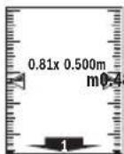
I3MepBaTeHnHrT ypeI n3MepBa HnpeKbChATo pa3CTOHNeTO Do HaayaHaTa ToUka. Ipn TOBa Ce IOKa3BaT eHOBpeMeHHo 3aJaDeHaTa Dbl3KHaHa N TeKyuata DaJnxHa. DOnHaTa, pecn. rOpHaTa CTpeNkA NOKa3BaT Ha-MaNKOTO pa3CToHnHe Do CneDbaUaTa, pecn. npexxOHaTa MapKnPOBKn.
YnbTbaHe: Pn HnpeKbCHaTo H3MepBaHe MoKeTe Da 3aJaTe TekyUaTa CToHoc KaTo CEeBa N Upe3 HaTnCKaHe Ha 6yToHa 4.
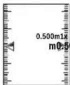
IЯВATA CTOHOC T NOKa3Ba KOJIKO NBTH 3aJaDeHaTa DbJxHa e6nHa doCTNTHATA.3eNEHHTe CTpeJIKN OTcTpaHN HaДиCПлЕЯ NOKa3BaT DOCTnRaHeTO HaDbJxHa c ceN MapKnpaHe.
H3mepBaHe Ha HAKNOH/LuΦpOB HnBEnIp
N36peTe N3MePbAe Ha NaKIOH/UNΦpOBA JIN6eNa
I3MepBaTeHnHrTypeCpePBeKlnOuBa aBToMaTHuHO MeKdy DBe CbCToHHa.
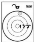
UHpOBaTaNb6ena CnyxN 3a npOBepKa Ha xOpnOHTaHTo HnBepTKaHNo NoppaBHraBaHe Ha oBeKT (HaNP. MnaHaMaHHa, XnaHnHK n T.H.).
Korato HaKNObHT HAnxBbpIN 3^ ,HaHcPiEe CBeTBA cepBHeHaToUka.
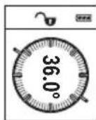
I3MepBaHeTo Ha KaKIOH CnyKx 3a I3MepBaHe Ha bTbN Ha HAcNOHeH IOBbPxHOCTn Hm MscJIeHN IpabN (Ha np. Ha CTbN6, npapaneTn, CBOIOBe 3a Me6eHn, pnppekapBaHe Ha Tpb6n nDp.n.).
Kato OTnpaBHa paBHHa npn n3MepBaHTo Ha NaKIOH CnyKIN JABaTa CTpaHa Ha n3MepBaTeHNH ypeI. Ako IIO BpeMe Ha n3MepBaHTo 3ano- UHe da MInrCABeTIINHHRT INDkAToP, n3MepBaTeHNH TyePe e HAKIOHEN TBbpDE CNlHO HAcTpaHI.
3anametrahe Ha H3mepeHH cTOnHOCTH
CToHocTtA, pecn. KpaHnT pe3yIaT O T BcKo IprNKIoUHIO N3MepBaHe aBTOMaTHUHO ce 3aHcBA.
3anaMeTeHH CToHooCTN
MoraTda 6bDat N3BnKbaHn HaH-MHO 30 cToHOCTH (N3MepeHN cToHOCTH INN KpaHH peyntaTH).
N36peTe cyHKnraTa 3aNaMeTBAHe


BbIrapckn | 405
B rohpata yact Ha nncnpe Ce NOKa3Ba HOMepbT Ha 3anaMeTeHa t cToHOCCT,OTdony -camaTa CTOHOCt,a OTNBA-ΦyHKUraTa,piu KOATo e 7.620m OIIa onpeDeneHa.
8.890m HaTNCHeTe 6yToHa 3 [+], 3a da ce npnBnKIne HAppeB 3anameHHTe CTOnHOCTN.
HaTnCHHe 6yToHa 8 [-], 3a Da ce npuBnKHTe Ha3aB 3aNaMeTeHInTe CTOnHOCTN.
AkoB nAmETTa HMa 3aHncaHa CToHocT, B DoHata YacCT Ha DnCnpe Ce N3o6pa3raBa ,0.000", a B rOpHaTa - ,0".
Ha-CTapata 3aNaMeTeHa cToHocT ce HAMpa B I03nue 1 B NaMeTTa, Ha-HOBata -B I03nue 30 (npn 30 HAnuHn KneTKn OT NaMeTTa).PpN 3aHNCBaHe Ha cNeDbau nCTOHOCTn Ce H3TPINBA BHNHaHn Ha-CTapata 3aNaMeTeHa cToHocT.
H3tpnBaHe Ha cbIbpxKaHHeTo Ha nAmETTa
3a n3tpnBaHe Ha cBbpxKaHneTo Ha naMeTTa HATnCHTe 6yToHa 7 [Func] n36peTe yHKzra 3anametBaHe . CneT OBa HAHTnCHTe KpATKOTpaH0 6yToHa 3a BKNIOBaHe n3KnIOBaHe 5 [c], 3a da n3TpneTe cToHOCCTHa dncnn.
Upe3 eHOBpemeHHoHaTnCKaHe Ha 6yToHa 4 n Ha 6yToHa 3a BKnIOuBaHe n 3KKnOuBaHe 5 [ ] ce H3TpNBaB BCnKn 3aNNcaHN B NaMeTTa CTOHOCTH.
Cb6npaHe/m3BaXkaHa He Ha cToHocTH
I3MepeHn Hn H3cncEn H cToHocTH MoRaT Da 6bDaT Cb6HpAHH nHn H3BaKaHaH.
Cb6npaHeHa cTOnHocTH
CneHnT npImep onncBa cbbnpaheTo Ha nlou:
OnpeIeTe nloTu, KaKTo e onHcHo B pa3JeN „N3MepBaHe Ha nlou“, BIXTe cTpaHua 401.
HaTnCHeTe 6yToHa 3 [+].HaIncnpeCe nokaBAt n3uHcneHaTa nlou m50.039 CUMBOJIbT,“
0.0°+93.406 m² HaTnCHHe 6yToHa 3a H3MepBaHe 2 [▲], 3a da 3aNoHHe cNeDbAio H3MepBaHe Ha NIOo, OnpeDeIe NIOoTa, KaKTo e OINcAo B pa3dEi „H3MepBaHe Ha NIOo", BIXTe cTpaHnca 401. Korato npKlnouh BTOPO To H3MepBaHe, pe3yNTaTbT OT Hero ce NOKa3Ba DOly Ha DnCInJe. 3a Da NOKaXeTe pe3yNTaTa, HaTnCHHe 0THOBo 6yToHa 3a H3MepBaHe 2 [▲]
YnbTbaHe:PnH3MepBaHe HaNbJnxHa BeDHa ca nOKa3Ba pe3yntaTbT.
3a n3n3aHe oT peKIma Ha cb6bnpaHe HATNCHEte 6yToHa 7 [Func].


406|Блгарский
N3BaXdAneHa cToHocTH
3a n3BaJdaHe Ha cToHocTn HaTncHeTe 6yToHa 8 [-].No-HaTaTBK ce npOeInpa aHa-noruHo Ha „Cb6bpAne Ha cToHocTn".
N3tpnBaHe Ha N3MepeHn cToHocTH
При BCИЧКИФУнкUNIЗа ИЗМерВан МОжTe Дa ИЗТриЕ ПОСлEDHО ИЗМерЕНА STОИHOCT Upe3 KpaTKOTpaHOn HAtNcKaHЯ ПуSCOBи ПпeKbCBaU 5 [ ] . HeKoJIKO-KpaTHOTO HATNcKaHЯ ПуSCOBи ПпeKbCBaU 5 [ ] BOДNo ITO ИЗТриВаHЯ ИЗМepeHHTe CTоHOCTH N B OБразн a PocLeДОВaTeHNOCT.
CmHa Ha MepHata eHHua
OchOBhata MePha eHnHua e m" (MeTbp).
BkIIOeTe N3MePbTaIeHHypeI.
3aIpbxTe HaTnCHaT 6yToHa 7 [Func], 3a Da BIne3e Te B MeHIO To, OCHOBn HAcTpOKn". N36epete ,ft/m".
HaTncheTe 6yToHa 3 [+] nnn 6yToHa 8 [-], 3a da cMeHHTe MePaTa eINHua.
3a H3JIH3aHe OT Ta3H ONIur HAHTCHETe 6yToHa 3a BKIIIOUBAHe H3KJIIOUBaHe 5 [ 心 ] H36paHaTa MEPHa eINHHua Ce 3aNa3Ba H CneJ H3KJIIOUBaHe Ha H3MEpBaTeJIHHypeJ.
Bluetooth®-nHTepdenc
Pa60ta cbc cTaTHB (DOnbHHTenHO npncnoc6neHHe)
N3noJI3BaHeTo Ha cTaTHB e Heo6xOJHMo OcO6eHO npu H3MepBaHe Ha rOJIeMHn DblJHKn. KaTO n3NoI3BaTe OTbopa C pe36a 13 3axBaHete ypeDa KbM IIOUkata 3a 6bp3o 3aXBaUaHe Ha cTaTHBa 19 mnn o6NKHOBeH cTaTHB 3a foToaIapatn. 3aTeHETe ro C BnHTa 3a 3actOnOpRAHe Ha nIOUkata 3a 6bp3o 3axBaUaHe Ha cTaTHBa.
IocTaBeTe cBoTBeTHO OTnpaBHaTa paBnHa 3a H3MepBaHe CbC CTaTINB Upe3 HaTnCKaHe Ha 6yToHa 4 (OTnpaBHa paBnHa pe36oBN OTbOp).
Cb06eHHe 3a rpewka
Korato n3MepBaHTo He MoKe Da 6bJe n3NbHeHo npaBnHOb, Ha dncnpe Ce noBBA cbO6eHHeTo 3a rpeWka „Error". N3KnIOUe Te n3MepBaTeHNnY ypeD, cIeD ToBa ro BKNIOUeTe OTHOB N NOBTOpeTe n3MepBaHTo.

H3MepBaTeHNrT ypeI cIeIa npaBnHToC nФyHKuOHNpaHe npn BcAko H3MepBaHe. Ako 6bJe ycTaHOBeHa NOBpeDa, Ha DnCnpeA ce NOKa3Ba cAmo CmBOJb TBCTpAHn, a H3MepBaTeHNrT ypeI ce N3KJIIOvBa. B TaKbB CnyaI ppeaIte H3MepBaTeHNrY ypeI 3a peMOHT Ha BaIIra TbProBeU INN B OToPn3HpaH cepBn3 3a eNeKTpOnHCTpyMeHTn Ha Boi.

PoiDbpxKaHe n cepBn3
PoiDlbpxKaHe n nouHCTBaHe
IopbpxkaTe H3MepeBATEHnYpeD BnHaHn YnCT.
He notonBaIte H3MePbAteJIHHy UpeB BBB BOa Hn Ipyr TeuHocTH.
H36bpcBaIte 3aMbpcBaHHaTc Meka, IeKo HbnaXHeHa Kbpna. He n3non3BaIte NoHCTBaIIN npenapATn nn pa3TBOpHTeII.
OThacnTe Ce CneuHaHO KbM PnpMaata JIeua 14 Cbc CbIoTO BHMaHHe, C KOeTo ce OTHacrTe KbM OUnHa Hn ObekTnB Ha oToanapat.
PnHoe6xOaMOCOT PemOH TpeIOCTaBAYe H3MePbAteINHyaHTaTa 16.

Bosch Power Tools 1609 92A 1RR| (26.11.15)


410|Блгарский
CepBn3 n TexHHueckn cbbetn
OTROBOPHnBaBbnpocHTeCNOTHOCHOpeMOHTaNIOdIpbkKaTaHaBaWnI npOdyKT MoKTe Da NOnyUHTe OT HaUNI cepBn3EN OTDen. MoTAtXHN Yeptexn HnHOpMaun 3a pe3epBHN uactm MOKeTe Da HAmepNTe CbIo Ha aDpec:
www.bosch-pt.com
EkntbHa Boa 3a Texnueckn CbBETn npnojKeHnue OTROBOpC yDIOBOJCTBne Ha BbnpoCte Bn OTHOCHO HauNTe npOyKTn n DoNbHHTenHNTe npncnoc6JeHnna 3a T8X.
MOn, npn Bbnpocn H npn npbUbahe Ha pe3epBn yactn BnHa nocOyBaTe 10-ntfpeHn KaTALIOKeH Omep, nncan Ha Ta6eKata Ha ypea.
Po6epr Bou EO0D- Bnrrapna
BouCepBn3LeHtbp
TapaHcNoHHn H3BbHrapaHcNoHHn peMoHTn
6yn. Yepn Bpbx 51-6
FPI Bn3HeC 1407
1907Cofn
Ten.: (02) 9601061
Ten.: (02) 9601079
a c (02) 9625302
www.bosch.bg
БракуВанe
I3MepBaTeHnHa ypei, IOnbHnHTeHnHte npncnoc6neHn H onakOBKHe Tp6Ba Da 6bDat nOIOJKeHn Ha ekONOruHa npepaBoTka 3a ycBOraBaHe Ha CbDbpxKaunTe Ce B Tx cyPOBHH.
He n3XbPnIe H3MePbTeHn ypeHn aKymyIaTOPn 6aTePN/6aTePN np6HTOBnTE OTnabu!
Cama 3a ctpaan ot EC:
CbflacHo Ebponecka dnpekTbBa 2012/19/EC n3mepBaTeHNupeHn HcflacHo Ebponecka dnpekTbBa 2006/66/EO akymaTOpHn HnO bHKHOBeHn 6aTePnH, KOtO He Moat Da ce H3non3BatNoBueYe, Tpa6Ba Da ce Cb6HpAT OTdEnHO n Da 6bDat NpDnaHn HaNpOxOJa ppepa6oTKa 3a OON3OTBOPraHe Ha CbDbpxKaIHTe Ce TBx CypOBHH.
ПпаваТа 3a ИЗмeн�у 3aNa3eHn.
1609 92A 1RR| (26.11.15) Bosch Power Tools


MaKeJIoHcKIn|411
MaKeDoHcKn
Be36eHocnHaNoMeHH

CHTe ynatCTBa Tpe6a Da ce npouHTaAT Ha da CE BHNMaBa Ha HNB, 3a Da moKe 6e36eHNO H 6e3 onachoc Ta pa6oTHte co OBOJ Mepenypei. DOKONky MEPHnotypei He ce KOPnCTn cornaCHO npnIOXeHNTe HHCTpyKuHH, MoKe Da ce Hapuyn FyHKnJaTa Ha BrpaJeHNTe 3aWTHTN MexAHN3Mn BO MEPHnotypei. He ja
OwTeyBaJte 03HaKaTa 3a npEynpeyBaHe Ha MEPHnotypeI. IO6PO UYBAJTE HOBNE YNATCTBA IN PPEADETE H3AEHO COMEPHNOTYPEI.
BHHMaHHe -DOKONky KOpNCTHTe Dpyn ypei3a NoDECyBaBe n paKyBaBe OCBeH OBDe HABeDEHnTE HIN NONHaKBN NOCTANKN, OBA MOKe Da IOBeDe Do ONaCHA H3IOXKeHOCT Ha 3pauebe.
MepHnOT ypeI ce nCnpaUyBa co HATNc 3a npEynpeyBaBe (O3NaueHo Ha npHKa3OT Ha MEPHnOT ypeI Ha rpaΦnKATA cTpHa co 6poj 12).
IEC60825-1:2014 <1mW, 635 nm
Laser Radiation Do not stare into beam Class 2 laser product
Dokonky TeKcTOn Ha HanelnHuaTa 3a npEynpeyBaHe He e Ha Baunot ja3NK, Bp3 Hero 3aneneTe ja HanelnHuaTa Ha Baunot ja3NK nped npBata ynotpe6a.
He ro hacouybajte nacepcknot 3paK Ha Nua HnN XHBOTHn He norneHybajte dIpeKTHo BO Hero HnN HerOBaTa peIekcnja. Taka moKe Da r3aclenTe NuaT, da npedn3BnKaTe HecpeKn nn Da rOwTeHTe OHTe.
Dokonky nacepcknot 3pak Docnee do ouhte, Behdau Tpe6a da ra 3aTbOpnte n da ja tprheTe rnaBata od nacepcknot 3pak.
He BpweTe HnKaBn npomEnHa naacepcknot ype.
He ngkopncTe nacepcknte ouhna kako 3aunTHn Ouyna. Nacepcknte ouhna cnkykat 3a noo6po npeno3HaBahe Ha nacepcknoT 3paK, Ho He 3aunTuYbaat OJ nacepckto 3pauehe.


412 | MaKeIdoHcKn
He rKopncTe Iacepcknte Ounna KaKO OUnna 3a cOnue HnN NAK BO co06paKaJot. Iacepcknte OUnna He DaBaat ceIocHa UV-3aHTnTa nro HaMaNy Baat npeno3HaBaHbeto Ha 6oN.
MepHnot ypeI cmee da ce nonpaba cmo od ctpaHa Ha KBaHnKkyBaH ctpyuH nepcoHAn co opHrHAnHn pe3epBn DeIOBn. CaMo Ha Toj HauHH Ke 6ndete cnryphn BO 6e36eHnocTa Ha MEPHnot ypeI.
He n octabajte deca t a ro kopctat nacepcknot mepeh yed 6e3 ha30p. Moke da rna 3acnenat npynte nua nopadn HeBHMmaHne.
He pa6oTe co MEPHnot ypeD BO OKOINHa KaJe NOCTOn ONaCHOCT OekCnNo3NJa, KaJe HMa 3anaNNB TeuHocTH, rac HnN npaunHa. MEPHnot ypeD COzdaBa NcKpN, KOH MoKe da ja 3ananat npaBt aHn napeata.
BHHMaHHe! PnK KopHCTeHbETo Ha MEPHNOT ypeD co Bluetooth® MoKe da HactaHaT npeKn Ha dpyrHte ypeHn cHCTeMH, ABHOHn MeiunHckn anapatn (Ha np. nejcMejkep, anapatuHba 3a cnUshaBe). UcTo taka He moKe cocema Da ce NCKnyat wTeHTHe BnJahnJa Ha lyreTo n XNBOTHTe BO HenocpeHata OkOnnHa. He ro KopHCTe MePNHOT ypeD co Bluetooth® BO 6bn3nHa Ha MednHcNk HpeDn, 6en3nHcNn pymn, Xemnckn ypeDn, ObnaCTn co onaCHOt oEKCnNo3nJa n BO 6bn3nHa Ha MmHcNn nnBa. He ro KopHCTe MePNHOT ypeD co Bluetooth® BO ABNOHn. N36erHyBajte DonroTPajHa yNotpeBa Bo DnpeKTHa 6bn3nHa Ha TeNoTo.
O3HaKaTc o 36OpOBu Bluetooth® KAKo H cInKHTe (noroata) ce perHCTpHpaHn TPROBcN MapKn u conCTBeHocr Ha Bluetooth SIG, Inc. Cekoe KopHcTeHe Ha OBaa O3HaKa co 36OpOBu/CInKu Ce BpuN co IHHcEHa npeky Robert Bosch GmbH.
OncnHa npOn3BODOT MOKHOCTa
Be monime OTBopete ja npeknoneHaTa cTpaHua ca npka3 Ha MepHnOT ypei, i dpkeTe ja OTBopeHa DoIeKa rO uHTaTe yNtCTBOTo 3a yNtOp6a.
Ynotpe6a co cooDbetHa HameHa
MepHnOTypeeHaMeHe3a MepeBe Ha daJeuHH,doJXHH, BucHH, pactoJaHja, KocHHn 3a npecMeTyBaHe Ha nobpUHHN BOyMeHH.
MepHnte pezyntaMuKeJa ce npenecaT ppeky Bluetooth*Ha npyru ypeNi.


MaKeDoHcKn|413
Texnuk noDaToCu
Executive Vice President
Head of Product Certification
Engineering
PT/ETM9

f_( 2) = h · m
Robert Bosch GmbH, Power Tools Division
70764 Leinfelden-Echterdingen, GERMANY
Leinfelden, 10.11.2015
Nynycpaunja Ha KOMnoHeHTn
HymepnpaheTo Ha cInknte co KOMnoHeHTe OndecyBa Ha npka3OT Ha MepHnte anapatn Ha rpaΦnukata CtpaHua.
1 EkpaH
2 Mepno konue[ ]
3 Konue Nync[+]
4 Konue H36op Ha pepepeHTHO HNO
5 Konue 3a BknyuBaHBe-ncKnyuBaHBe [ ]
6 Bluetooth®-konue
7ФункинскКончe[Func]
8 Konue MInHyc[-]
9 Pokloneu ha npperpaata 3a 6atepnjata
10ФИКСИРаБЕHA NOKЛОЕЦТЯпERраДАТа 3a 6aTepeNJa
11 Cepnckbpoj
12 Hatnnc 3a npdeynpeyBaHe Ha nacepot
13 1/4"-Haboj Ha CTaTnBOT
14 PnemHaJIeKa
15 N3ne3 Ha nacepcknoT 3paK
16 3aHTHa TaHa
17 LcHnHa Ta6Na 3a NaacepoT
18 Nacepckn ouhna
19 CtaTHB
*OnnhaHata onpema npkkaKaHa hcnKHe e eno cTaNdapHnot o6eHa Hcnpaka.


416 | MaKeDoHcKn
EnementHa npka30T (n36op)
a Ctauyc Bluetooth®

Bluetooth® aKTHBnpaH, He e BOCNocTaBeHa Bpcka

Bluetooth® aKTHBnpuH, BOCNocTaBeHa Bpcka
b PepeHTHO HNO HA MepeHeTo
C Pnka3 Ha 6aTeepu
d PeoBn co n3MepeHaTbpeHocT
e PeDobu co pezynTaT
fMepHnФyHKcnn
gPnka3Ha aorHa 3aKocyBaBe
h CTaTycHa neHTa
i OCHOBHNIOCTaBKN
Mоntаха
CtBaIbe/MehyBaIbe Ha 6aTePnH
3a pa6ota co MepHnotypece npenopayBa KopncTeHe Ha aIkaIHO-MaHraHcN 6aTePn.
Co 1,2-BOIHTH6aTePnN Ce BO3MOXHN IOMaIKy MepeHa OTKoIky Co 1,5-BOITH6bATEpH.
3a da ro OTBOPHTe KanaKOT od nperepaDATA 3a 6atepH N pntncheTe Ha MexaHn3MOT 3a 3aknyBaHe 10 n 3BaTeTe ro kanaKot od nperepaDATA 3a 6atepH. CtaBeTe rN 6atepHte BHaTpe. PnToA BnMaBajTe Ha NoNoBHe BO corNaCHoc T Co npHKa3OT Ha BHaTpeShHata cTpaHa od nperepaDATA 3a 6atepH.
ДOKONКУ OЗнakata 3a 6atepnja ce nojabn 3a npB nat Ha ekpaHOT, MOXHN CE yuTe OKNY 100 Mepeha.ДOKONKY OЗнakata 3a 6atepnja e npa3Ha n TpeNka UpBeHo, He MOne da Мрпte. 3aMeHete rH 6atepnite ODH. AkymyNatopHite.
Cekoraa 3aemeHyBaJTe r n cte 6atepno OeHa. Kopnctete caMo 6atepn oed H npOn3BODHTen CO hCT KanaNTet.
Dokonky He cTe ro Kopnctene MEPHnot ypeI NOBeKe BpeMe, n3BaTe Te 6aTePHTe oI Hero. Dokonky ce noDIOr BOpe Me CKlaIpaH, batepHTe MoKe da KopoDIPAaT I Da ce ICnpa3HaT.


MaKeJIOHcKn|417
Ynotpe6a
CtBaIbe Bo ynotpe6a
He ro octabajte BknyuyeHnoT Mepen ype6e3 Haad3Op HcknyuyeTo no ynotpe6ata. npynte Iua MoKe da ce 3acnenat od nacepcknO 3paK.
3aunrTe rO mepHnOT ypeI OJ Bnara HnpeKTHo N3IOxKyBaBe Ha COHueBN 3paui.
He ro n3noxybajte MEPHnot ypeed ha ekctpeMHN TEMnepaTyprn HnH ocunauu BO Temnepaypata. Hanp. He ro octabajte dOnro BpeMe BO aBtOMobHnot. Pnp rOlenm ocunauu BO TemnepaTpata, octabeTe ro MEPHnot ypeed HajnpBO da ceakImMaTHnpa, nped da ro cTabte BO ynoTpe6a. Pnp ekCTpeMHN TemnepaTyprn HnOCUNauu BO TemnepaTpata, npeun3HoCTa Ha MEPHnot ypeed MoKe Da ce Hapuyn.
H36erHybajTe rnyapnTe n npebptybaBataHa MepeHnot ypeI. IIO cnHn HauBopeuHN BnjuHjaHa MePNOT ypeI, nped da ro ynoTpe6nte 3a pa6ota, Cekorau H3BpWeTe KOHTpona Ha ToUHOCTa (BNDn,InpOBepKa Ha ToUHOCT npn MepeHe Ha paoToJaHna", cTpaHa 427).
BknyyBaBe/ncknyyBaBe
- 3a BKNyCyBaBe Ha MEPHNOT ypeI N Iacepot npHTNCHeTe KpaTKO Ha KOuTeo 3a MepeHe 2 [▲].
- 3a BknyyBaBe Ha MEPHNOT ypeI 6e3 Iacep, npHTNCHeTe KpaTKO Ha KOuTeTo 3a BknyyBaBe-ICKnyyBaBe 5 [ ]
He ro hacooybajte 3paKOT CBeTnHa Ha Nmua Hn JN BOTHn He norneHybajte dHpeKTHO BO Hero, Dpyn Hn OD rOleMa OndaneueHoCT.
3a ncknyyBaBe Ha MePHNOT ypeI dpxKeTe ro KOnyeTo 3a BknyuBaHeNCKnyuYBaBe 5 [ ] npTnCHato.
PnHcKnyuBaHe Ha MePNHOyEi, BO MemOpjata OCTaHyBaAT 3auyBaHN BpeHOCHTe I NOCTaBKNTe Ha ypeDTo.
PpOuecHaMepeHe
По BKnyuBaHBeTo, Мернnot ypeIce HaOra BO ФункиJa HaДОлЖИСКо МереHbe. 3aДугмepHa ФункиJa npTnCHeTe Ha KonueTo 7 [Func].ИЗбepTe ja cakHaTa Мерна ФункиJa co KonueTo 3 [+] Ипн KonueTo 8 [-] (ВИдn,МернфункиN" cTpaHa 419).Актуврajte ja Мерна ФункиJa co KonueTo 7 [Func] Ипс co KonueTo 3a МереHbe 2 [▲].


418 | MaKeDoHcKn
Kako pepepeHTHO HNBO 3a MepeHe, no BknyuBaHbeto, e n36paH 3aHnOt pa6 Ha MepHnOt ypeI. 3a npomeHa ha pepepeHTHO HNBO BnI „BnpaHbHa pepepeHTHO HNBO", cTpHa 418.
IocTaBete ro MepHnOt ypei Ha cakaHaTa CTapTHa ToUka Ha MepeHe (Ha np. sU).
HAnomeHa:IOKoNky MepHnoTypeIce Bknyu Co KOnueTo 3a BknyuBaHe- NCKnyuBaHbE5 [c] npHTnCHeTe KpaTko Ha KOnueTo 3a MepeHbe2 [▲] 3a da ro BKnyuTe NacepOT.
3a akTHBnpaHb e Ha MepeHbTo, npHTNCHeTe KpaTKo Ha KOuTe 3a MepeHb 2 [▲] . Itoa nacepcknot 3paK Ke ce ncknyu. 3a pyro MepeHb NOBTOpeTe ja OBaa noCTanka.
He ro hacouybajte 3paKOT cBeTnHa Ha Nnca HnN XNBOTHn He norneHybajTe dIpeKTHO BO Hero, Dpyn Hn OD rOleMa OndaneueHoCT.
Hanomeha:Boo6nuaeHo,ImMepeHaTbpeHnOcCe noJaByBa BO pOK od 0,5 c,a HajdoHa nO okony 4 c.BpeMeTpaeHeTo Ha MepeHeTo 3aBnCn OD paCtoJaHneTo, CBeTIOCHHTe YcNOBn H pePfKeTHpaUKN CBOJCTBa HA CEJIHATA NOBpUHa. ITO 3aBpUyBaHe Ha MepeHeTo, IacepCKnOT 3paK aBTOMATCKN Ke ce NCKnyu.
BnpaBe Ha pepepeENTHO HNBO (BnDn cInka A)
3a MepeHbTo MoKeJa n36epeTe Tpr pa3nHn pepepENTn HnBOa:
-
3aHnOt pa6 Ha MePnOTopei (Ha np. npn OoTbYBaBHe Ha SIOBOH),
-
npedHnoT pa6 Ha MepHnoT ypei (Haip. npi MepeIbe, noHyBaJKn oJ edeH pa6 Ha Maca),
-
cpeiHa Ha HABoJOT 13 (Ha np. 3a MepeHb co CtaTnB).
3a n3bop Ha pepeepentHO HNBO, pHTNCHETe ro konueTo 4. Co konueTo 3 [+] nnn KOnueTo 8 [-] nnn KOnueTo 4 n3bepeTe ro cakHoTo pepeepENTHO HNBO. No ceKoe BknyBaBe Ha MEPHnotypeEd, 3aHNOT pa6 Ha MEPHnotypeEd e npetXoDnHO noctabeH KaKO pepeepENTHO HNBO.
MeHH ,OCHOBHnIOCTABKN
3aДаВлeЗеTO BO MEHHTO „Осовн NOCTaBKN“ (i),Држete ro npHTnCHaTO KONUETO 7 [Func].
I36peTe ja ODHOCHATA OCHOBHa NOCTaBka H HeJ3HNOTo NoDEcyBaBe.
3aДаиЗлесеTe OД МЕнITO,ОсOBHи NOCTaBKN",ПпТИСЧeTe Ha KONчeTo 3a BКлувВаБe-ИСКлувВаБe 5 [ ]


MaKeDoHcKn|419
OcbetnyBaHe Ha ekpaHot
OcbetnyBaHbeto Ha ekpaHot e HnpeKHaTo BKnyeHo. OkoIky He npTncHe Ta KaOnyeto, OCBtnyBaHbeto Ha ekpaHot ce 3aTeMHyBa no OKoly 20 cekyni 3apaN 3aHTnTa Ha 6aTePnTe/akymyNaTopnTe.
Mepn yHKuH
MepeheHaDOnxHHN
H36peTe MepeHe Ha DoJxHHI
3a BknyuBaHBe Ha IacepcknOT 3paK npHTncHe Te KpaTko Ha KOJIeTo 3a MepeHBe 2 [▲]
3a MepeHe npTnCHeTe KpaTko Ha KOJIeTo 3a MepeHe 2 [▲]. N3MepeHaTa BpeHocT Ke ce npKaeJe Dony Ha ekPaHoT.
3a ceKoe IOHaTaMOH OMepe He NOBTopeTe rTOpeHaBeDeHHTe 电KOpH. IocneHnA tN3MepeHa BpeHOCCT cTOn dony Ha ekpaHot, a 8.890 m npETnoCneHnA Hd Hea nTH.

MepeheHaBpeMeTpaebe
При КОТИнунуразно Мере,并,Мернот урд може релатувно да сдвжп концета, пи StTo Измерената Вредноct ke ce axурпа на секо 0,5 c. Habл. можеда сддалачпес Heke paTojaHne od snodt, a MOMeHTaJIHOT paTojaHne ceKORAшКе bideчITINBO.
H36peTe KOHTnHynpaHO MepeBe I
3a BkIyBaHbHe Ha IacepcknOT 3paK npHTncHE Te KpaTKO Ha KOJIeTO 3a MepeHBe 2 [▲]
ДВИКЕТо Мернотуpeдdoideka He ce npikakke 6apahoto pactojaHne doIyHa ekpaHOT.
KpaTko npnTnCKaHe Ha KonuTeTo 3a MepeBe 2 [▲] To npkeHyBaTe KOHTnHynpaHOTo MepeBe. AkTyEnHata N3MepeHa BpeHocT Ke ce PnPKae DoIy Ha ekpaHOT. HAd Hea CTOJat MaKcMAnHata MInHMaHATA N3MepeHa BpeHocCT. Co OndHO Bo npNTnCKaHe Ha KOnuTeTo 3a MepeBe 2 [▲] KOHTnHynpaHOTo MepeBe OndHOBO CTapTuBa.
KoHTnHynpaHTo MepeHe aBtOMaTcKn Ce NCKnyuYBa no 5 MNH.

Bosch Power Tools 1609 92A 1RR| (26.11.15)


420 | MaKeDoHcKn
Mepehe ha noBpuHHN
I36peTe MepeHe Ha noBpUnHn □
Ha KpaJ, 3MepeTe ja DoJxHnHa T uHpHnHa eHNO NO pyro KaK MepeBeto Ha doJxHH. Nomey DBeTe MepeBa, nacepcknoT 3paK OCTaHyBa BknyueH. Tpacata WTo Tpe6a da ce H3Meprn TpeNka Ha npKa30 Ta noBpUnHcKO MepeBe
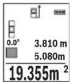
Ipbata n3MepeHa BpeHocKe ce npkaKe rope Ha ekpaHot.
No 3aBpuBaBe Ha BTOPOTo MepeBe NOBpHnHaTa ABtOMaTcKn Ke ce
npecMeTa n npkaKe. KpajHnoT pe3yntAT cTOn dOly Ha ekpaHot, a
NoeINHeuHTe n3MepeHn BpeHocTHn Haid Hero.
Mepebe Ha Bonymeh
N36peTe MepeHbe Ha BonyMeH
Ha KpaJ, H3MepeTe ja 7npuHata, DOnxHHata N dna6ouHata eHNO no dpyro KaKo Kaj MepeBeTo HaDOnxHH. IOMeIy TpIte MepeBa, NacepckNt 3paK OCTaHyBa BKNlyueH. Tpacata WTo TpeBa da ce H3Mepr TpEnKa Ha npka3OT 3a MepeHe Ha BOJyMeH
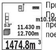
bata n3MepeHa BpeHocT Ke ce npKaege rope Ha ekpaHot.
BaBpUyBaHe Ha TpeTOTo MepeBe BOJMeHOT aBTOMaTcKn Ke ce
CMeta n npKaeke. KpaJHoT pe3yIaT cToN dOly Ha ekpaHOT, a
dINHeuHHTe N3MepeHN BpeHocT Na Hero.
HnnpekTHo MepeHe Ha pactoJanHa
3a HnIpeKTHo MpeHe Ha pactojaHna,Ha pacnoIarabe Bn ce Tpr MeHN yHKun, CO KOn MoKe da Ce CoONuTat pa3nHn TpaCn.
HnIpeKTHOTo MepeHe Ha pactoJAHJa CnyKn 3a COONHTyBaHe Ha pAcTOJAHJa, KO He TpeBa DnpeKTHO Da Ce H3MepaT, Bndejkn NMa npeuKn BO TEKOT Ha 3paKOT NnHEMa CEHa NOBpUHa KaKO pePfKeKTOp Ha pacNoJaraHe. OBaa MepHa NoCTanKa MoKe da ce npImeHN Camo BO BeptHKaJIeH Ipabeu. Cekoe OTCTanyBaHe BO XOpN3OHTaJIeH Ipabeue BoN KO MepHn TpeKKn.
HAnomeHa: INdInpeKTHOTMepeHe Ha pactoJahJa e cekoraawnoTOHO Od INpeKTHOTMepeHe Ha pactoJahJa. Bo 3aBnchOCT od npimehata, MePHnte rpeKIM MoKe Da Ce NOrOJIeMn OD INpeKTHOTMepeHe Ha pactoJahJa. 3a NIObOpBaBe Ha MEPHaToUHOCT npeNoPAuYBaMe KOpNCTeHe Ha cTaINB (onpema).
Pomey noeHHeuHHe MepeBa, IacepcknO 3paK OCTaHyBa BknyueH.


MaKeJIoHcKIn|421
a) HnHneKTHo MepeHe Ha BnCHNn (BnH cnHa B)
I36peTe HnHnpeKTHo MepeHe Ha BnCnHn
BHHMaBaJTe Ha Toa, MepHnot ypeI da e Ha hCTa BnCnHa KaKo HdoNHaTa MepHa TouKa. IToa HabAte Ro MepHnot ypeI OKony pepepeHTOto HBO H3MepeTe ja TpaCata KAKo Kaj MepeHe Ha DoJXnHata,"1" (Ha ekpaHOT e npkaKaHa KaKO uPBeHa NnHja).
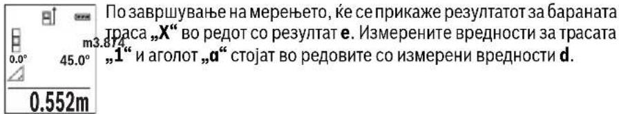
b)Дбови Индөртхм eрөе Ha Bнснн (Bнн cннka C)
MepHnOT ypeI MOKe Ia rH N3MepN dHpeKTHO CHTe TpaH, KOnuTo Jekat Ha BepTKaJIHO To HnBO Ha MepHnOT ypeI.
I36peTe IBOJHO HINHnpeKTHO MepeHe Ha BnCHN
I3MepeTe Tn TpaCHTe KaKo np MepeHBe Ha DoJxHHN,1" n,2" no Oboj peDocneI.
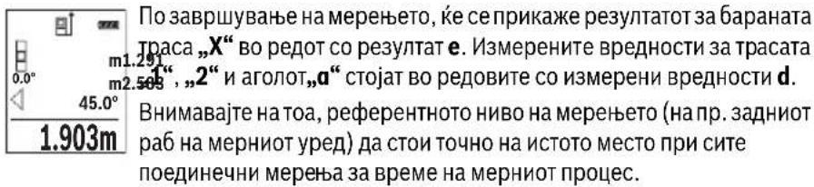
c) HnHneKTHo MepeHe Ha IOnXHHu (BnHcnKka D)
H36peTe HnDnpeKTHo MepeHe HaIOnJKNHn
BHHMaBajTe Ha Toa, MEPHnotypeJa eHa HCTa BucnHa KaKo N 6apaHaTa MEPHa TocKa. IToa HabaIeTo MEPHnotypeOKonypepepENTHO HNBO H3Mepete ja Tpacata KaKo Kaj MpeHe Ha DonJxHATA,1".
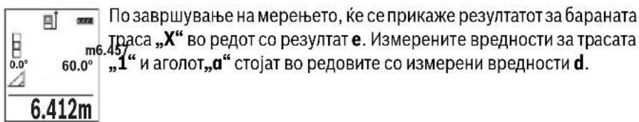


422 | MaKeIdoHcKn
Mepehe Ha sHdHH noBpuHHn (BNDn cNka E)
MepeheTo Ha sNHN NOBpHHcnyKDa ce do6ne 36np Ha noBeKe nnoeHnH NoBpHH co 3aeHNuKa BnCnHa.
Ha npimepot co cnilka tpe6a da ce odpeH BkyhHaTa NOBpHnHa Ha NOBeKe sHIOBN, KOHMAAT nCTa BNCnHa H npocTopoT H, Ho pa3nHn DOJxHn L.
N36peTe MepeHBe Ha SInHn NOBpHnH
I3MepeTe ja BnCnHaTa Ha IpoCTOpOT H kaKo np MepeHeTo Ha DoJxHn.
I3MepeHaT BpeHocT Ke ce npKkae Bo rOpHnOt peHa H3MepeHH BpeHocTH.
JaacepoToocTaHyBa BknyueH.
IToTa H3Mepete Ja doJHKnHaTa LHa npBnOT sHd. NObpHHaTa 1A TOMaTcKn Ke ce npecMeTa nKe ce npkaKe BO peoT co pe3ynta e. 2.583m IocNeHaTa H3MpeHa BpeHocT Ha doJHKnHa CTOn BO doJHnOt peDco 2.583m H3MpeHN BpeHocT d. Nacepot octaHyBa BKnyueH.
3.336m Cera n3MepeTe ja dOJIxHnHaTa L2 Ha BtOpHOT sI. PpHKaKaHaTa NOeHNHeuHa BpeHOCr BO peoT Ha n3MepeHn BpeHocr d ce DoJaBa
HaONXnHaTa L.Cymata OJ DBeTe ONXnHn (npKacKaHa BO CpeHNOT peCo H3MepeHH BpeHocTH d) ce MHoxn CO 3aUyBaHaTbBcHnHa H. BkyHnHa T BpeHocT Ha NOBpHHaTe Ke ce npKae Bo peoT co pe3yntaH e.
MoKeJaMepHe DoJxHnNoXe6aL,The aBtOMaTcKn Ke ce DoJaat NKe ce NOMHOKAt CO BucHHaTa H.
YcnoB 3a ToHa npecMeTKa Ha NOBpHHHe e, nPBata H3MepeHa DOJxHnHa (BO npIMepoT BnCnHaTa Ha IpocToPOr H) da e NdeHTnHa 3a CHTe JeIOBn OJ IOBpHHHe.
OCHOBHATA NOCTABKa e MepHaTa eINHnua ,m" (MeTap).
BknyteToMepHnOypeI.
Држete ro npHTnCHaTo konHcTe 7 [Func] 3a Da BHe3eTe BO MeHInTO „OCHOBHn nocTaBKn".ИЗбepete „ft/m".
PnTnCHeTe ro konyeTo 3 [+] nn konyeTo 8 [-], 3a da ja npomeHnte MepeHaTa eHNHua.
3a da n3ne3eTe oJ TOUkata Ha MeHHTO, pHTNCHeTe Ha KOnyTe 3a BKnuyBaBeHCKnyuBaBe 5 [ ] .IIO NcKnyuBaBe Ha MepHnOT ypeI, n36paHaT a NoCTaBka OCTaHyBa 3auyBaHa.
Bluetooth®-MHTepejec
Ipehoc Ha nodaToCuHa dpyrH ypeH
MepHnOT ype e onpemeh co Bluetooth®-Moyn, Koj co nomoHa paAno Texnka OBO3MOxyBa IpeHoc Ha nOdaToCuI Do oDpeHn MObInH TePMHaHn Co Bluetooth®- HnTeppejc (Ha np. cMapTfoH, tabnet).
HnΦopMaun 3a NOTpe6HNTe CnCTeMckn PpeDyCNOBn 3a Bluetooth®-Bpcka Ke HajTe Ha HHTepHET CTpaHata Ha Bosch Ha www.bosch-pt.de
OctaHaTHe HnΦopMaun Ke rH npohajTe Ha cTpaHaTa 3a npOH3BOoT Od Bosch, Bndete ro QR-KoDoT, cTpHa 8.
Pn npenoc Ha noaToCu Co nomoHa Bluetooth MoKe Da HacTaHbpeMeHcKn OndoxyBaHa nOmeRy MoBnHnOT TepMnHa N MepHnOT ypei. Oba moKe da ce cnuyu npaOn OndaJeHoCTa Ha Dbata ypeN nn CamnOT MepeH objekt.


426 | MaKeIdoHcKn
AkhBpahe Ha Bluetooth®- HHTeppejc 3a npehoc Ha noaToun Ha Mo6Hneh TepMHan
3a aKTHBnpaBe Ha Bluetooth®-HHTepjejcot npHTNCheTe Ha Bluetooth®-KoNueTo 6Ha MepHnot ypeI. 3a aKTHBnpaBe Ha Bluetooth®-CnHAnOT npHTNCheTe OndHOBo Ha Bluetooth®-KoNueTo 6 Hn KOnueTo 3 [+]. IpoBepete daHn Bluetooth®-HHTepjejcot e aKTHBnpaH Ha BaUnOT MObIneTepMnHaI.
3aHaIpa6bHa o6eMoT Ha cyHKuHn Ha Mo6HnHOT TepMNHa n 3a
PoeIHOCTaByBaHe Ha Oba60Tkata Ha NDoAToU Ha pacNoIarHe IMaTe CneJauHN
Bosch-annKaun (Apps).The MoKe Da ce npE3EmAT BO COoDBeTHNe IpOdaBHnCn
BO 3aBnCHOC Td TepMNHaNt.
IIO CTAPr Ha Bosch-annkaunjata ce BocnoctabyBa Bpcka nomey MObHnOT TepmHaJI MepHnOT ypeI. IOKONky ce npohajdeHn NOBeKe AKTNBn MepHn ypeI, H3bepeTe ro COoDBeTHnOT MepeH ypeI co nOMOu Ha cepncKnOT 6poJ.
CtatycoT Ha NOBp3yBaHe KaKo N aKTINBHaTa Bpcka (a) Ke ce npHKaKaT Ha CtatyChaTa IHHJa (h) Ha MEPHNOTypeI.
IeakTNBnpahe Ha Bluetooth®- nHTeppejc
3a DeaknBnpaBe Ha Bluetooth®-Bpckata npntnche Ta Ha Bluetooth®-KonyeTo 6.3a DeaknBnpaBe Ha Bluetooth®-CnHAnOT OndHOBo npntnche Ta Ha Bluetooth®-KonyeTo 6 nnn KonyeTo 8 [-] nnn ncknyuTe rO mepHnot ypeI.
Cobetn npn pa6oTeheTo
OctaHaTHte HnΦopMaunKe rH npohajTe Ha cTpaHaTa 3a npOH3BOoT Od Bosch, Bndete ro QR-KoDoT, cTpHa 8.
MepHnOTypee onpemeh co 6e3xHuEn HHTepfejc. Tpe6a da ce BHHMaBa Ha IOKaHNHe OnepaTHBnH OrpaHnUyBaHa,Ha np.Bo aBHOH HnN 60HNuN.
OnwTH HanomeHH
PnemHaTa neka 14 nH3ne3oHa Iacepcknot 3paK 15 He CmeaT da 6nDaT NOKpneHn 3a BpeMe Ha MepeHeTo.
3a BpeMe Ha MepeHbTeO, MepHNoTypeI He Cmee Da ce DnKHe. IOKoNky e BO3MOxHo, nocTaBeTe Ro MepHNoTypeI Ha Ubpcta POnlora.
BnnaHjaHa MephoTo nOe
MepHOTo nOle 3aBnCH oD CBETNOCHTe yCIOBn H peΦneKTNBHTe CBOJCTBa Ha ceHnata NOBpUHa. Ipn jako HADBOpeuHo OCBeTnyBaHe, 3a noDo6pa BnINBOcT Ha nacepcknOT 3paK, KopNCTe TE 3aHTTHn OUYHa 3a Nacep 18 (onpeMa) H cElnHa Ta6Na 3a Nacepot 17 (ONPeMa), INI 3aceHete ja cEHNATA NOBpUHa.


MaKeEOHcKn|427
BnnaHjaHa MePnOpeyntaT
IopadnФH3NcKHeMeKHe MeKe Da ce NCKnyu KaTOT,Kea npu MepeBeTo Ha pa3NCHNOBpHHDoafo NorpeuHO MepeBe. Tyka cnafaaT:
TpaHcnpaepHTNIOBpuHHN(Ha np.CtaKIO,BOda),
- NOBpHnH hTo peΦneKTHpaat (Ha np. nCnoHpaH metan, cKaNo),
- Nop03Hn NOBpWHHn (Ha np. 130laHNOH MaTepnjAn),
- ctpyKtypnpaHH NOBpHNN (Ha np. rpy6a MaTepnja, npnpoeh KaMeH).
Iokonye BO3MOxHo,HaOBHe NOBpHnH KopncTe Te cenHa Ta6na 3a Iacepot 17 (onpema).
IpeuKn npm MepeBeTo ce nTo TaKa MoXHn Kaj HaKOCo Bn3npaHn ZenHH NOBpWHN.
IcTo Taka Ha MepHaTa BpeHIOCT MoKe Da BnJaAT I npOeNHe 3a BeHTNaJca Co pa3nHuTe TMnpaTpHi Hn HnDInpeKTHo PpIMeHrte pePneKcn.
PpOBepKa Ha ToUHocTa H KAnI6pHpAbeTo Ha H3MepeHnte KocHH (BnH cNkKa G)
PeIOBHO npOBepyBaJTe ja ToHocTa Ha MepeBeTo Ha KocHH. OBa Ce BpHn Co nOMoH Ha MeHyBaHe Ha npabeUOT. NocTaBeTe ro MEPHnOT ypeI Ha eHa Maca H3MepeTe ja KocHHata. CBrTeTe ro MEPHnOT ypeI 3a 180^ n OndHO BO h3MepeTe ja KocHHata.
Pa3nkaTaNomefny npKkKaHnTe n3Hocn CMee da n3HeCyBa MaKc.0,3°
Pn rOlen MOn OTCaNyBaHa MePNHOypeN MOpa OndHOBa Da Ce KaHbnpa. PnTOa H36peTe CneTe ryn yNaTcTBaTa Ha ekpaHot.
IIO rOJEMn npOMeHn Ha TEMpepatypata n no ydApn, npenopayBaMe da ce H3BpShn pOBepKa Ha ToUHOCTa n EB. KaIIbprpaBe Ha MEPnOT ypeD. IIO npOMeHa Ha TEMpepatypata, MEPnOT ypeD MOpA da CE npINarOIn Ha HopMaHata TEMpepatypa HeKoe BpeMe nped Da ce H3BpShn KaIIbpaunja.
PpOBepKa Ha ToUHOCT npMpeHe Ha pAcToJAHJa
ToHocTa Ha MePHNOT ypeM OMeJa ja npOBepHTe Ha cneHNOB HauHH:
-
I36epete eHNO HENPOMEHINBO MEPHO IOpaue co DOJKNHa oD OKOly 3do 10 M, uJa DOJKNHa TOUHO ja 3Haete (Haip. UHNpHaTa Ha IpocTojuTa, OTBOPOT Ha BpaTata). MepebeTo Tpe6a Da ce BpUnPi NIOBONH yCNoBn, T.e. MEPHO To nppaue Tpe6a da 6nde BO BHTpeuHnot npocToP nCenHata NOBpHnHa Ha MepeBeTo Tpe6a Da 6nde Ma3Ha n Do6po da peFneKtnpa.
-
NImpeTe ro noJaapeJeTo 10-naTHn eoHNo no npyro.
OCTanyBaHTo OcpeHaTa BpeHoc Pn PoeHHeHHTe MepeHa CMee da H3HeCyBa MaKChMym ± 4 MM Ha ZelIoTO MepHO NoJpaJe Pn NOBOLHyCNoBn.
3aHHyBaJte rH MepehBaTa, 3a Da MoKe NIOOuHa da Ja CnOpeIte ToHocTa.


428 | MaKeIdoHcKn
Pa6oTehe co cTaTHB (onpema)
KopncTebeTo Ha cTaTHBOT e Oco6eH NoTpe6Ho npn rOJeMn pactoJahJa. MepHnotypeCo 1/4"-Haboj 13 nocTabete Ro Ha 6p30 IpomEnIbA IIIOa Ha cTaTHBOT 19 HnHa BOo6uHaeh FOto-CTaTHB. LbpcTo 3aIpaFte ja 6p30 3aMeHNbata IIIOya co 7paФ 3aФNKcnpaBe.
CoOdBetHO NoCTaBeTe ro pepepeHTHOTo HnBO 3a MepeHe CO CTaTHBOT, Co npHTNcKaHe Ha KonTueto 4 (pepepeHTHO HnBO 3a HABoj).
Iopaka 3a rpewka
ДOKOLKY MepeHbTo He MoKe Ja ce npaBnHO da ce n3BpSh, Ha ekpaHot ce npkaKBy npakata 3a rpeWka „Error". NcknyeTe ro MEPHOT ypeN noBtOpHo BKnyeTe ro N OJHOBO CTApTyBaJte ro MepeHbTo.

MepHnoT ypeJa KOHTpOInpa TOnHaT a FyHKcNJa PnP cKeOe MepeHe. DOKoNky ce yTBpDn DepeKt, Ha ekpaHOT cToN cAmO O3HaKaTa NOKpaJ HrO n MepHnoT ypeJce NCKnyuBa. Bo BAKOB cIyaj npedaeTe ro Baunot Mepen ypeJ ppeKy Baunot TproBeu Ha cepBnchata Cnyx6a Ha Bosch.
OdpkyyBaHe n cepBnC
OdpKyBaBe n uHcTeBe
IocjoaHO odpxyBajte ja uHCToTaHa MePHIOr ypeI.
He ro notonybajte MePHnoT ypeI BO BOa nn npytn TeuHocTH.
I36pnse Tn HeuCTOTnTE CO BnaXHa MeKa Kpna. He KopncTeTe cpeIcTBA 3a nCHe Hn paTbOpn.
Ocobo OdpjyBaJe ja npHemHaIeKa 14 co nctata rpnka, co koja Tpe6a da ce oDpKyaat ouHnata nn IeKaTa Ha foToanapaT.
Bo cnuyaj da tpe6a da ce nonpaBn, npateTe ro MepHnot ypeD BO 3aHTnHaTa TaHa 16.
CepBncha cnIyK6a n COBeTH npN KopncTeHe
CepBnchata cnjx6a ke odroBOpn Ha BaunTe npaaBa Bo Bpcka co nonpaBkata n OnpKyBaHcTo Ha BaunOT npOn3BoD KaKO n pe3epBnTe DeNoBN. EKcnno3nBeH uTKe HnΦopMaun 3a pe3epBn DenOBn Ke HajndeHa:
www.bosch-pt.com
TMMOT 3a coBetyBaHe npi KopncteHa Bosch Ke BN NOMORHe DOKOKy HMaTe npaShaBa 3a HaWHTe npOn3BODn ONpeMa.
3a cnte npaaHa n HapaKn Ha pe3epBn DeNoBn, Be moIne HaBeTe ro 10-ncfpeHHOT 6poj od CneuHkaauHOHa TnOuKa Ha npOn3BOoT.
1609 92A 1RR|(26.11.15) Bosch Power Tools


Srpski 429
MaKeDoHnJa
Д.Д.Енковс
CabaKobayek47Hb,6poj3
1000 Ckonje
E-nouta: dimce.dimcev@servis-bosch.mk
DOBRO SACUVAJTE OVO UPUTSTVO I PREDAJTE GA ZAJEDNO SA ALATOM, AKO GA PROSLEDUJETE DALJE.
- Oprez - ak se koriste drugi uredjaji za rad ili povesevanje od onih koji su ovde navedeni, ili izvode drugi postupci, moze ovo voditi eksplozijama sa zračenjem.
Bosch Power Tools 1609 92A 1RR| (26.11.15)


430 | Srpski
Merni alat se isporuceje sa Jednom upozoravajucom tablicom (u prikazumernog alata oznacena na grafickoj stranici sa brojem 12).
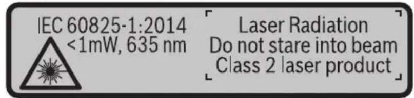
Ako tekst tablice sa opomenom nije na Vašem jeziku, onda prelepite ga pre prvog puštanja u rad sa isporucenom nalepnicom na jeziku Vase zemplje.

Ne usmeravajte laserski zrak na osobe iliŽivotinje i sami negledajte u direktan ili reflektujuci laserski zrak. Na taj način možete dazaslepite lica, prouzrokujete nezgode ili da ostetite oci.
Ako lasersko zračenje dode u oko, morate svesno da zatvorite oko i da glavu odmah okretene od zraka.
Nemojte da vršite promene na laserskoj opremi.
Ne koristite laserske naocare za posmatranje kao zastitne naocare. Laserske naocare za posmatranje sluze za bolje prepoznavanje laserskog zraka, one ne stite od laserskog zracenja.
Ne upotrebljavaje laserske naocare za posmatranje kao naocare za sunt ilu putnom saobracaju. Laserske naocare za posmatranje ne pruzaju punu UV zastitu i smanjuju opazanje boja.
Neka Vam merni alat popravlja stručno osoblje i samo sa originalnim rezervnim delovima. Time se obezbedjuje, da sigurnost mernog alata ostaje sačuvana.
Ne dopu staje deci korijscenje mernog alata sa laserom bez nadzora. Oni bi mogli nenamernozaslepiti osoblje.
Ne radite sa mernim alatom u okolini gde postoji opasnost od eksplozija, u kojoj se nalaze zapaljive tecnosti, gasovi ili prase. U mernom alatu se mogu proizvesti varnice, koje bi zapalite prasinu ili isparenja.
Oprez! Ako upotrebljavate merni alat sa Bluetooth® moze da nastupi smetnja za druge uredaje i postrojenja, avione i medicinske uredaje (npr. pejsmejkere za srce, slusne aparate). Takodeijke sasvim isključen negativan uticaj na lijude iŽivotinja u neposrednoj blizini. Merni alat sa Bluetooth® nemojte da upotrebljavate u blizini medicinskih uredaja, pumpi za tocenje goriva, hemijskih postrojenja, zona sa opasnosću od eksplozije i minskih polja. Merni alat sa Bluetooth® nemojte da upotrebljavate u avionima. Izbegavajte režim rada na duži vremenski periodu direktnoj blizini tela.


Srpski 431
Bluetooth® naziv marke kao i slikovne oznake (logoi) su registrovane robne marke i vlasništvo Bluetooth SIG, Inc. Za svaku upotrebu ovog naziva marke/slikovnih oznaka Robert Bosch GmbH poseduje licencu.
Executive Vice President
Head of Product Certification
Engineering
PT/ETM9

f_( 2) = h · m
Robert Bosch GmbH, Power Tools Division
70764 Leinfelden-Echterdingen, GERMANY
Leinfelden, 10.11.2015
K部件sa slike
Laser Radiation Do not stare into beam Class 2 laser product
Ce tekst opozorilne tablice ni v vašem jeziku, ga pred prvim zagonom prelepi-te z ustrezno nalepko v vašem nacionalnem jeziku.
Henk Becker Helmut Heinzelmann
Executive Vice President Head of Product Certification
Engineering PT/ETM9

Robert Bosch GmbH, Power Tools Division 70764 Leinfelden-Echterdingen, GERMANY Leinfelden, 10.11.2015
K部件 na sliki
Laser Radiation Do not stare into beam Class 2 laser product


Bosch Power Tools 1609 92A 1RR| (26.11.15)


464 | Hrvatski
Ako tekst natpisa upozorenja nije na vašem materinjem jeziku, u tom slučaju prije prvog pušanja u rad, preko ovog natpisa upozorenja nalijepite isporčenu naljepnicu na vašem materinjem jeziku.

Executive Vice President Head of Product Certification
Engineering PT/ETM9

Robert Bosch GmbH, Power Tools Division
70764 Leinfelden-Echterdingen, GERMANY
Leinfelden, 10.11.2015
Laser Radiation Do not stare into beam Class 2 laser product


Eesti481
OBJ_BUCH-2450-004.book Page 484 Thursday, November 26, 2015 10:46 AM


484|Eesti
Vastavus normidele C
Executive Vice President
Head of Product Certification
Engineering
PT/ETM9


Robert Bosch GmbH, Power Tools Division
70764 Leinfelden-Echterdingen, GERMANY
Leinfelden, 10.11.2015
Seadme osad
OBJ_BUCH-2450-004.book Page 488 Thursday, November 26, 2015 10:46 AM


488|Eesti
Pidev moötmine
Laser Radiation Do not stare into beam Class 2 laser product
Ja bridinosas uzlimes teksts nav jusu valsts valoda, tad pirms pirmas lietoanas pärlimejiet tai pari kopā ar merinstrumentu piegadato uzlimi jusu valsts valoda.

Neversiet lazera staru citu personu vai majdzivnieku virziena un neskatieties tieja vai atstarotaja lazera stara. Sada riciba var apzilbinat tuvuma esosas personas, izraisit nelaimes gadijumus vai pat bojat redzi.
Executive Vice President
Head of Product Certification
Engineering
PT/ETM9

f^ ( x) = - ( 2x + 1) ( ax - 1) x = 0
Robert Bosch GmbH, Power Tools Division
70764 Leinfelden-Echterdingen, GERMANY
Leinfelden, 10.11.2015
Interfeiss Bluetooth®
Datu parraidisana uz citam iekartam
Mérinstruments ir aprikots ar Bluetooth® moduli, kas pa radiosakaru kanalu lauj parraidit datus uz noteiktam, ar interfeisu Bluetooth® apgadatam mobilajam gala iericem (pieméram, uz smartfonu, plansetdatoru u.c.).
Informaciju par sistemas limena prieksnoteikumiem, kas nepieciesami Bluetooth sa-vienojuma nodrosinasaanai, var atrast Bosch interneta vietne ar sadu adresi: www.bosch-pt.de
Sikaka informacija ir atrodama Bosch izstradajumu lappuse, skatit QR kodu lappuse 8.
Veicot datu parraidisanu ar interfeisa Bluetooth® palidzibu, starp mobilo gala ierici un merinstrumentu var rasties laika aizture. Tas var notikt gadijumā, ja ir liels attalums starp abam ericem vai lidz meriisanas objektam.
Interfeisa Bluetooth® aktivizēsana dato pārraidisanai uz mobilo gala ierici
Lai aktivizetu interfeisu Bluetooth®, nospiediet merinstrumenta taustiñu Bluetooth® 6. Lai aktivizetu Bluetooth® signalu, vélreiz nospiediet taustiñu Bluetooth® 6 vai taustiñu 3 [+]. Nodrosiniet, lai butu aktivizëts mobilas gala ierices interfeiss Bluetooth®. Lai paplasinatu mobilās gala ierices FUNCIONalitäti un vienkäršotu dato apstradi, ir pieejamas ipañas Bosch lietojumprogrammas (Apps). Tás var lejupieladet no attieci-gá veikala atbilstoşi esosajai gala iericei.
Pec Bosch lietojumprogrammas palaisanas tiek izveidots savienojums starp mobilo gala ierici un merinstrumentu. Ja ir vairaki aktivi merinstrumenti, izvelieties vajadzigo merinstrumentu pec ta serijas numura.
Laser Radiation Do not stare into beam Class 2 laser product


Bosch Power Tools 1609 92A 1RR| (26.11.15)


516 | Lietuviškai
Henk Becker Helmut Heinzelmann
Executive Vice President Head of Product Certification
Engineering PT/ETM9

Robert Bosch GmbH, Power Tools Division 70764 Leinfelden-Echterdingen, GERMANY Leinfelden, 10.11.2015
(21gll j) gll lI I I I I I I I I
j. pIglll lI I I I I I I I I I I I I I I I I I I I I I I I I I I I I I I I I I I I I I I I I I I I I I I I I I I I I I I I I I I I I I I I I I I I I I I I I
Ic bai Ii a no pialgall ylll lalil g uiaaull sllwxl (gimbo 4 jll
1
.(lb)“Error”1bJgJgB!p,sUuWwUaLacJlaLg .1d0 wUaJI IyIg LglzwiX 1 pWuJI Ixsc JLoyP
aLac J5 20 yIgll lA aLw aIjy jwIaI Isc gai
bag jgl JoJ aWlI jy jbp Ibc aIwS Ila .wIg
wIaI Isc pIwB aq ,dIJI o .wIaI Oc agg
.ao Jolaj JIJI JIJI Jn o wB sLac ao ss

Jw
jbl jwJl l c w g y b aagg go g logall no jall
.8aQQR sgs
aJlI JgJgJgJgJgJgJgJgJgJgJgJgJgJgJgJgJgJgJgJgJgJgJgJgJgJgJgJgJgJgJgJgJgJgJgJgJgJgJgJgJgJgJgJgJgJgJg
.1
dole Udo
aLac |j| sic 15 juUg 14 uaw aus jy
U
0scg g Uc uol l. wlll 1w lal ooc jy j
.uyjIksjI abw gI sao abw lc wlaJI
wlll jso lgc
. 1 a b i o j k l s o j k l j k j k j k j k j k j k j k j k j k j k j k j k j k j k j k j k j k j k j k j k j k j k j k j k j k j k j k j k j k j k j k j k j k j k j k j k j
p saiwI o yduWl aunjIuI oLkI uLa jJuU I eauu Juaq JauLso
pIeI pIg (LALJ) 17 JJU U yuagg (LALJ) 18JJU U a g
.9gell aabio
wll 10 jolgc
wLg sic auiu juii uui wuw l c abu uwug uun
:laioo joo.doliao gbw
(LJl:LjJl):
(gj1Ug
(aJgJgJ
( ( n + 1) - 1) = ( ( n + 2) - 1) ( ( n + 3) - 1)
.0jgJlSic 2gBwU oJc (gIg) 17 juU Jnuii aJ Uos
J 1
.
J 1
. 山 山 aog Lcjg julu o
(G oJgJJI) JJI JI JI JI JI JI JI
.ajilg jwug aloc Jda no eJ pai .paiaio JSw Jolj wug aa
JgJ.1111 1g oia 1c wlaal osc n jn i y p
aJgjg-1g 180°Jd
.120g 120≤0,3° aogjooJI
poll . 10 no wuall ooc yle c k b b g g
.awl lccgagll laeall gcal CAL jai
5 1g jj l
Lijao jiaolbuiolguluoll
Bluetooth
sJjU UJIJI
UuUuuu uuuuueauuueuuuuuuuuuuuuuuuuuuuuuuuuuuuuuuuuuuuuuuuuuuuuuuuuuuuuuuuuuuuuuuuuuuuuuuuuuuuuuuuuuuuuuuuuuuuuuuuuuuuuuuuuuuuuuuuuuuuuuuuuuuuuuuuuuuuuuuuuuuuuuuuuuuuuuuuuuuuuuuUU
JUJI JUW Uc) Bluetooth auiu uogu ojoo uua uo j
(gUJguaSJI SJJlgl
aee bteoth8 Jlaiy A gllal laljwI jg aag
gall u jj
www.bosch-pt.de
jbl jjly lglggyaiao ggo loglaal no jall
.8 aQQR sgs
J 1
.
Jl jLjUuUuUuUuUuUuUuUuUuUuUuUuUuUuUuUuUuUuUuUuUuUuUuUuUuUuUuUuUuUuUuUuUuUuUuUuUuUuUuUuUuUuUuUuUuUuUuUuUuUuU
.6 Bluetooth 6Bluetooth ® auiu u
[+]3jj1g6Bluetooth 6Bluetooth
.
gj g jg jg jg jg jg jg jg
.ajaiJI jaiJI g jaiJI caiBill oJjiLiAs. (Apps)
g. wll o 0 g l l j 1 1 1 1 1 1 1 1 1 1 1 1 1 1 1 1 1 1 1 1
wll 0x jai aai wai sao
JUULI JAAJb jc auiol
(h) aJbR (a) JJI JI JI JI JI JI JI JI JI JI
L
Bluetooth 1
a 6 Bluetooth® jj lcbnbluetooth ®
g[-]8jj1g6Bluetooth@jIcJbD,Bluetooth@jLw!
.μuLoo
jS1JJ
bawl pJ. 0jS1JJ aabg jalg [Func] 7 JJI Jc bawl ojSlJJ gao
.5 1g jj 0
5 1g jg 4 jll c gll m oj
.0jSJJ 0gagal gao
aJb/2
.1g g aIgill aIilg wIaII p q 80
PJI 0
:UuUuuuUUuuuu
.542 aJl "UaIuI I u" jU I b aIuI U u
.“+”j0jIg auiuaiiaaiuaii jIqbi [+]3jjllbc
.1sclai ajjal pall [+] 3 jll lc bol .ljl ajjal pall [-] 8 jll lc bol
"0.000" aaii jjll oag jawl jj 0a aai jg j 1j .“0” aai lclg
30 gol 1 aag 12g 12g 12g 30
(EgJgJj)JJdJLwO
oJiaogbawalwogao yLgagjy jdAalwos
.ujuoo glajj
gai jn jn jn nn nnnn nn nnnnnnnnnnnnnnnnnnnnnnnnnnnnnnnnnnnnnnnnnnnnnnnnnnnnnnnnnnnnnnnnnnnnnnnnnnnnnnnnnnnnnnnnnnnnnnnnnnnnn
LulgBd aolio LgiJg H oJ
.1JdlaLwmoUg jai
wIaJI aJbJ .Ugbl I wIg sic UJl gLoH oJyAaI aIwO wIyBp
JjU| jU. UaI I aI JgUJI J
LloggJ .UgJlJdU L UgbI Wlaq,
wugaojgbi.eailljbwjgig aalolll
jUJ. d wIaI aai JwI JwI Jg
2.583m
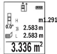
wIaI aag adllo! p. 1111 L2 b0gbl wIoo
L1UgblJdUwulalaojpwadogjolll
(d wlll aolw gJl pssll (j)nglgog
.e aaii I baw g aIlaXl aalwai aag jbb.H uiaIg lojXl
Lgoggl Lg 111x gblgbln ju k uauu
H eaijai g aiaa g
()UgIwIaIuIgIaIwIyIaIawllwIaIbJw
aui jui Uaiuui (H aoi jui glojil
(FgJgJj) gJJI bIaI aIbIg
J 10000000000000000000000000000000000000
aai jai g aiaaiaaaai iag aaii aai iai iai iai
. jio 50 elbuol Ug b g 0,1
gJbBaaabg jai
/0jll jai [Func] 7 jll pssw, kdy piau. ggcjll ugbll b
.[-]8jjgl[+]3jjl pI sawu Iaol Jy Bg jol gol
2 1j jg 10 g d 100
wulaiabaojjc sby
- Jjaiwly abai aal wlaowll wlaol o gao
g g. aJll JwIaJI aagg Jgbl Jgb] iJ
aJg aIwI aJg I aIwI JawI gI gJI
jjI Ic bdoJl do no loi kaiu wuol
.1Jgbs aWloao aag SuJ8
(BgJglj)uLgEaJlWla (a
.
J 1 1 1 1 1 1 1 1 1 1 1 1 1 1 1 1 1 1 1 1 1 1 1 1 1 1 1 1 1 1 1 1 1 1 1 1 1 1 1 1 1
"X" aIbll aIwll n c aII lI I wIaI I aIoc pia 1
"0" aIgIg "1" aIwll wIg loI e aII I baw
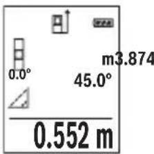
(CgJgJgJ) ccloo JwLpaegelajl wLg (b
0JU 111111111111111111111111111111 1 2 3 4 5 6 7 8 9 10
"X" aIbll aIaI I c aIiI I J e IaI I aI aI I aI aI I aI I aI I aI I aI I aI I aI I aI I aI I aI I aI I aI I aI I aI I aI I aI I aI I aI I aI I aI I aI I aI I aI I aI I aI I aI I aI I aI I aI I aI I aI I aI I aI I aI I
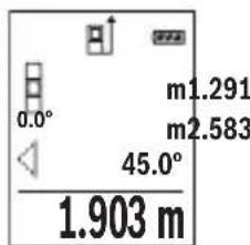
DgJgJ) JUJgUgBJUgC
1bUwUaJIuCwUaJIjai
aI aI I aI aI aI aI aI aI aI aI aI aI aI aI aI aI aI aI aI aI aI aI aI aI aI aI aI aI aI aI aI aI aI aI aI aI aI aI aI aI aI aI aI aI aI aI aI aI aI aI aI aI a
"X" aIbll aIwll n c aII lIaI IaIac pia 1
"0" aIgllg "1" aIwll wIq loI e aII I bW g
d wIq I q JbW J

LJI
□
wlll.1g21 wlaag llll y gllg uol jy waaagjll
□
.aauull lcl uuaaagugjg jy Jgog g Lg jy JUwJg Jauu Jy JUuall Jg UJUu Jy JUu Jy JUu
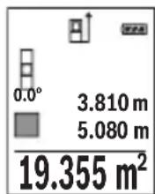
gJUw
□pLgUwLgjai
.1g 1u g Ls blll g uolgl g jss s y
□plaalwulg uL
aawlll lglwlaaggugjz jbi. aoe g llogig p 111111111111111111111
Lg9
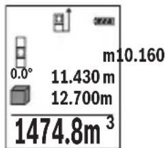
jLgJcUkBswIg
wIaIgio J5 aawg, wIy gJkSbWdS WlaIg Wlaq Iag
.àoliao lgluo
JwLgWgXgXgXgXgXgXgXgXgXgXgXgXgXgXgXgXgXgXgXgXgXgXgXgXgXgXgXgXgXgXgXgXgXgXgXgXgXgXgXgXgXgXgXgXgXgXgXgXgXgXg
.1uSlo 1uww gjg jgl aal Jluo guc ucl liu u
Jl jai 1 J. bao gao oJyI yI yI yI yI yI yI yI yI yI yI yI yI
LJ 15gWg
aaii iia aiaiaiaiaiaiaiaiaiaiaiaiaiaiaiaiaiaiaiaiaiaiaiaiaiaiaiaiaiaiaiaiaiaiaiaiaiaiaiaiaiaiaiaiaiaiaiaiaiaiaiaiaiaiaiaiaia
.1 1 1 1 1 1 1 1 1 1 1 1 1 1 1 1
(1gll) glll l l l l l l l l l l
.1J 1111111111111
aWuI L
JjI JI IJI IJI IJI JI JI JI JI JI JI JI JI JI JI JI JI JI JI JI JI JI JI JI JI JI JI JI JI JI JI JI JI JI JI JI JI JI JI JI JI JI JI JI JI JI JI JI JI JI JI JI JI JI JI J1
wIJI Ig
UgBgU
Ugbluuljai
[2 wll jj lgl ggl jllgwl 1w wll aag . [2 wll jj lgl ggl wll wll
aag jg jgl g 1s wlg 1gddll oolg kdoal lgbll J .1ssg g aai I gaaai Ig g g awl lawf awla
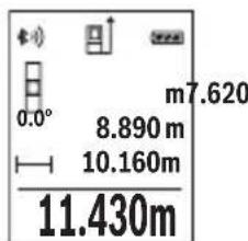
jaiu wu
ai lale jaiiall waiall sic d qul auiuill waioll oxc kns jn j 0,5 uaiiaaaiwai iaiiaaae gao. lais lalil jaii iikwuggjolll
[12 wJllJJIgGgIgIgIgIgIg]
12 wll jy 10 g 1000000000000000000000000000000000000000000000000000000000000000000000000000
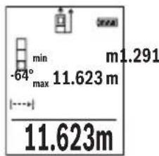
wJJI aJoc
w g g. jg.11 g g g g g g g g g g g g g g g g g g g g g g g g g g g g g g g g g g g g g g g g g g g g g g g g g g g g g g g g g g g g g g g g g g g g gg. [Func] 7 jjlllglbgsj, (543 a, "w qlll lglg" jil) [-] 8 jjllgl[+] 3 .[A]2 w qlljj pdsaswblg [Func] 7 jjllpdsaswblg wqlll wqlll wqlll wqlll wqlll wqlll wqlll wqlll wqlll wqlll wqlll wqlll wqlll wqlll wqlll wqlll wqlll wqlll wqlll wqlll wqlll wqlll wqlll wqlll wqlll wqll l wqlll wqlll wqlll wqlll wqlll wqlll wqlll wqlll wqlll wqlll wqlll wqlll wqlll wqlll wqlll wqlll wqlll wqlll wqlll wqlll wqlll wqlll wqlll wqlll wqll
Jj
Jg JgJg
4 0,5 Jd Jg aaw laaia jzabdo
WJL WJG oJg jbg aguall Jc wlaal .g g. jS21
. logjJJU Ew Lb p y wlaal lgil .d qll abio
(A oJgJJI j) J liWJI gJU
:adol sliw luguog uo 1n j wull aolc slwlgusu moj
Executive Vice President
Engineering
Helmut Heinzelmann
Head of Product Certification
PT/ETM9

i.v. h · m _____
Robert Bosch GmbH, Power Tools Division
70764 Leinfelden-Echterdingen, GERMANY
Leinfelden, 10.11.2015
Jgssal 1j
a a o gagall wll o gw j l o gaoal 1j
.ububuul gwJl
awwJ1
[△]UJjj2
[+]jjjj3
J1wJgWJj4
[ ] 5
Bluetooth 6
[Func]g 7
[-] u#glljj8
UjIbUJ oAa 9
UJIULI OJSSUBc 10
JulwioJI pJI 11
jjU-ji 12
aog 1/4 lJlI Jg 13
| EPTA-Procedure 01:2014 | |
| (20 H 5 | - jzj -(q'zj) |
| EPTA-Procedure 01:2014 | |
| (20 H 5 | - (q'zj) |
| EPTA-Procedure 01:2014 | |
| (20 H 5 | - (q'zj) |
| EPTA-Procedure 01:2014 | |
| (20 H 5 | - (q'zj) |
| EPTA-Procedure 01:2014 | |
| (20 G 5 | - (q'zj) |
| EPTA-Procedure 01:2014 | |
| (20 G 5 | - (q'zj) |
| EPTA-Procedure 01:2014 | |
| (20 G 5 | - (q'zj) |
| EPTA-Procedure 01:2014 | |
549
auiul
| (A) 50-0,05 | (,) noisy |
| (B) 20 | (j) noisy, noisy (,) noisy (,) noisy |
| (A) 1,5± | (j) noisy (,) noisy |
| (B) 3,0± | (j) noisy (,) noisy (,) noisy (,) noisy |
| 0,1 | |
| 0°-360° (4x90°) | |
| 0°-360° (4x90°) | |
| (C)/D)/I) | (j) noisy (,) noisy ± 0,2° |
| -10°C...+45°C) | |
| -20°C...+70°C | |
| 1 > , noisy | |
| (D) 9 | (,) noisy 25 (,) noisy |
| (D) 45 | 10 (,) noisy - noisy |
X. gJgJgJgJgJgJgJgJgJgJgJgJgJgJgJgJgJgJgJgJgJgJgJgJgJgJgJgJgJgJgJgJgJgJgJgJgJgJgJgJgJg
oo 1oI Ic abal all Jn o g. bao aolJl jIg 1laawlg .uIJI
Igogg .aJg ju gJjUwLg 0s oLdawy JabW aW W .gaoo uK uR uR uR uR lacly
0sc jjwll 1. gI JJIgI JJIgI JIgWlU .0JgI oJwq
Bleoth 80000000000000000000000000000000000000000000000000000000000000000000000000000000000000000
Lg g aJy Jn Jn Jn Jn Jn Jn Jn Jn Jn Jn Jn Jn Jn Jn Jn Jn Jn Jn Jn Jn Jn Jn Jn Jn Jn Jn Jn Jn Jn Jn Jn Jn Jn Jn Jn Jn Jn Jn Jn Jn Jn Jn Jn Jn Jn Jn Jn Jn Jn Jn J.
sJg aaiJl oog
gai iagao 1s g uai jll o s g wj o g jall aai all aai al .JlsswKl aWJ
Jaaal Jlaaew
JgJg UlaJg UcljXlg JIgBg JIgJgUaJgUaJgO.
.
Jl

wlll bds jlll laln llg o g g q g k l k l l l l l l l l l l l l l l l l l l l l l l l l l l l l l l l l l l l l l l l l l l l l l l l l l l l l l l l l l l l l l l l l l l l
1g liu Iw k jyll jz g 10k jyj yd wl n - wjal .bbs cew! u jy lI yds q d s Joc yllwq bpi
4 0e gw L
.(12 pJU aBbI I gWJI Aa Jc WJI
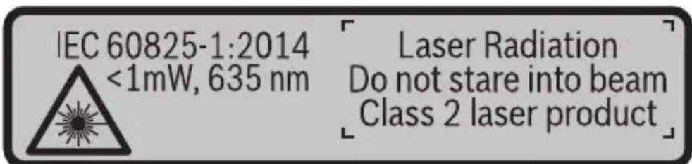
a aal lgl qlll jy baa ylaal ll aaflll glll n jn 1. gai jaoi oia wai jq ai baa aqjai
g g uulgglg lgljllg d g 1
wyyu. uaiy gl jlllgl 1
jglgglgglgglggl

-1JUUL eLw Jc
A
- jjUJqUc
gJjU A gJ U Jb j 1g JJIbIs JJU A gJ U Jb j pSsW J JU U LcA W | no y Jg JU U Ee A gJ U K So|
J 1 J 1 J 1 J 1 J 1 J 1 J 1 J 1 J 1 J 1
LgJdJglgCgSgSg
aoli jn nn p q 11 s 11 g g g g g g g g g g g g g g g g g g g g g g g g g g g g g g g g g g g g g g g g g g g g g g gg.
.ubgao 5jduai g 10
()duu uJg
Jj. CwI pJg g g g g g g g g g g g g g g g g g g g g g g g g g g g g g g g g g g g g g g g g g g g g g g g g g g g g g g g g g g g gg
UpaL
Jai daa Jd EorRg 1s bpa y jol jil s y plj p 00 g J S ojl g i jlg g g gol a l j j. g w o jll .
Goo J 1s oJol s Jg S OJol Jj I
OoIc 5b aogd aod, dui c d j.
J .g w 0 w gola oJol sll j! g D G o Jw jil
Ssi laj j 5y L o sioggrdj l y 8g oJol Jj 1j
Bosch

uugw9 CJol
oLswJjSgJgJ,
. 150 j j j j g oj j j j j j j j j j j j j j j j j j j j j j j j j j j j j j j j j j j j j j j j j j j j j j j j j j j j j j j j j j j j j j j j j j j j j j j j j j j j j j j j j j j j j j j j j j j j j j j j j j j j j
Sjolsl aJ j sJl Julgc
j 0j jol pds jnabobn jg j g jolgc d d j. w y aui s g g ojl j Jl aiaa g baw
:jl sjjjuc jolgc
()1duwuwU
-(duu,oω
-10siiS GlcS1
- ( L_j 2 ) ( 1 - 2 )
. 11 11 (1) 17 jj j j j j j j j j j j j j j j j j j j j j j j j j j j j j j j j j j j j j j j j j j j j j j j j j j j j j j j j j
.wwl jSoo JJ siwU oW u
paaaoojoc jso1 sglg g glao slloos lg w ddo
. 1j j j j j j j j j j j j j j j j j j j j j j j j j j j j j j j j j j j j j j
(Ggajd gwhgj) uu ojlul puiu g oLsws Jus
. d u
10jmuo -.uJy ojl jI p
J 15 J 15 J 15 J 15 J 15 J 15 J 15 J 15 J 15 J 15 J 15 J 15 J 15 J 15 J 15 J 15 J 15 J 15 J 15 J 15 J 15 J 15 J 15 J 15 J 15 J 15
Lai duu lao
JL W 0
U
j 6 Bluetooth® dSBluetooth
6 6u Bluetooth aos oJg Bluetooth Jus u
Jl jLw oLsw dBluetho 8 Jd s gwhnab.
.
10 dolj, cIcIbI JaiJl JauW g Jauw oKuS sJSLoc paa slaJI U
Egj uJ gJ Lo J dolj j. Dsgo Bosch (Apps) 5
.5iS 5j j ggo lio jI oLsw
S oJl jI g J Ios S Jn bI Bosch (App) 5 dolj gJ
jIjI, cIiOJg oJiSIL gJl jI jD Jg Dg
.5iS 1aiil Jjw oJaw SsS aJJuJbJ sJgO
jJ jI (h) cL a J (a) Jgblj gbljll
.8gwh00s1
Bluetooth 1JU
6 Bluetooth 6Bluetooth
1j[-]8doSS6UBluetoothaossoJugSBluetoothuLiswunssu
.
Jac sl Jai
Bosch 0gao jI J Uw
.8 .QR-Code
JSLgDgOa. CwI jao algo I S o dS u Jil Jj!
.
Lg g lalbl
oJg jolj 15 ju g g g 14 Jd
.
gj j gjol jglgjnl .Jn Js Jk oJl j
Jg CbBw Lsoo oL aSj
s jil o g d o jil jil jil jolgc
S 1000000000000000000000000000000000000000000
18jJlSicjIgjgogpOojjIgJg
uIj GwBwU SsO LaiW (Lalso) 17 JJg (Lalso)
.ajlui
.001 1g j gj d j gj ojl p k
.duJl [Func]7 1s dss,egaoo jds sji
oojol jSg jao
g>duo oolalw. jlai []-8doL ojl j
.duo «lo ojl jS
oJ 0jI J I J I J J J J
L5sLac pai juugj 5 uogj-uugol daS oUgS juuh L Sdo sOUGS nJuW Jy SjL y. SsOjJdJd
.5 jwj- wgo
jolalg jogai
.()《m》gjolglalglpaa
. 1j sJ oJ JlJl
. 山 _ 1 ^ 山 11111111111111111111111111111111111111
.1SU|Jft/m
.15g 1j g ojl jal alg l j dss j 8 aos s [+]3 aos
jUw.5JlwhI [5nWgJ-Wgola dS JdJil jJ j
.
Bluetooth® Jau
LkwS Lw dclb| Jai
bWgiJlclblalaswbyjogbeo Bluetooth® pwwu wuyu jslj1j
(1) (_i=1^n)
.oo Go Jlai
Jl j 1j Bluetooth@ jblj bjjj jj jj jj j j j j j j j j j j j j j j
Lai jg
www.bosch-pt.de
Bosch jI Jl IJ Lw
8 QR-Code
Jn Jn Jn Jn Jn Jn Jn Jn Jn Jn Jn Jn Jn Jn Jn Jn Jn Jn Jn Jn Jn Jn Jn Jn Jn Jn Jn Jn Jn Jn Jn Jn Jn Jn Jn Jn Jn Jn Jn Jn Jn Jn Jn Jn Jn Jn Jn Jn Jn Jn Jn
1 1 1 1 1 1 1 1 1 1 1 1 1 1 1 1
. 0jol jggoaawu yjdyj1 oJww g
oJd Jdo Jduloi
. 30 jsl
.
.50mU CwI Jg0.0,1mU CwI Jg
.1sS Ulaill j 15uS ojl sll Jl Sj Sloc
aouo ojdl jolgoadlaog aouo joldl c:agj gaj b cwl nks ojdl glb. cwl jas dalq ojl jn jy. sinbl dlq aoos ojdl jj yw wol .pki Gdgi (cll) aydu w jj laoi W 50 Go jn wgj (s ojl s) drn slg ojl dlal j ju gj
(Bgawd gwhgj) paoa o jgbj e lajI oJsi (a
.
oJsl abaii iIwSy IaJI (gj gS oJdl JjI d Sis Cg
oJsl siil g jil y aBw jg J (jS oJdl JjI uww .uLy S
1 (0 w 01s n lwi JoJb bAnlgic dy jgiiaa J) 《1》muu Ugb Su
. SiS OJdJI
X 10000000000000000000000000000000000000000000000000000000000000000
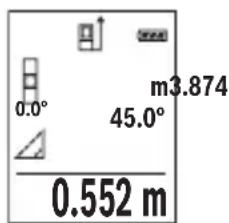
(CgjgawgJ) paaa aagbglg 1
oJljljI gac baw dS I J Lwmaa daa jg o sK oJljljI l
.5S 5j5 oJ Sj Poo Jc .SjI Jg
.1uI I J 10000000000000000000000000000000000000000
.15 2>g<1> 10
Xg j 100 g a 100 100 100 100 100 100 100 100 100 100 100 100 100 100 100 100 100 100 100 100 100 100 100 100 100 10
JjI jI JI JI JI JI JI JI JI JI JI JI JI JI JI JI JI JI JI JI JI JI JI JI JI JI JI JI JI JI JI JI JI JI JI JI JI JI JI JI JI JI JI
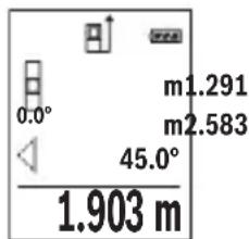
(Dgaaa gawgj) paaa aagbgbgbs jsl (c
. 15
Jg g o jol al abai y cww ojl jj1 dS s S Jol 10 g 1 j j 10 w g j 1 g o jol jj .w b
J 1 J 1 J 1 J 1 J 1 J 1 J 1 J 1 J 1 J 1 J 1 J 1 J 1 J 1 J 1 J 1 J 1 J 1 J 1 J 1 J 1 J 1 J 1 J 1 J 1 J 1 J 1 J 1 J 1 J 1 J 1 J 1 J 1 J 1 J
《山I 1
J. 1 J. 1 J. 1 J. 1 J. 1 J. 1 J. 1 J. 1 J. 1 J. 1 J. 1 J. 1 J. 1 J. 1 J. 1 J. 1 J. 1 J. 1 J. 1 J. 1 J. 1 J. 1 J. 1 J. 1 J. 1 J. 1
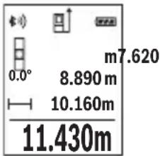
dawguy 5jol jogai
0000000000000000000000000000000000000000000000000000000000000000000000000
.1S U 1J-4 dWg y SjS oJ Jl
. 2 1s jil s daS JJJJg j 1j 1 1 1 1 1 1 1 1 1 1
AaJusg.
13ogjjbwg-(duLdWU Lw
y[-]8doS y[+]3doS.1sJ4doS,goaawlaai oJsljIjI jI jI jI JI JI JI OgJg 4doS .owOswuJyjI jI jI gic dy
0j1j1 100 s, w ju b uai a d a a y i y jy c | yjia jy joo oj1j1 a w l y jy b y c | yjia jy .w| noo y
.1sL agej I sjjw L golg slu. wlu
. 150 1 1 1 1 1 1 1 1 1 1 1 1 1 1 1 1 1 1 1 1 1 1 1 1 1 1 1
.
i 1 /L
JU 10000000000000000000000000000000000000000000
.1gawduaogao gao g oaw jjjg gawj
oLswJg
oLswJjJgaj
g d s j l j j j j j j j j j j j j j j j j j j j j j j j j j j j j j j j j j j j j j j j j j j j j j j j j j j j j j j j j j j j j j j j j j j jj
.1JUgag JyUolawIpa
ggsj g j g 1g g gg j j j j j
.
g (s) g
JU JUoJgBj jSs oJsiJJjI .dss JJddw dJdJd
10 10
Cwwl jjbl, CwI JJn Bluetooth

5u 0j1 jil 4a b
SjI JsWuJ C
lo ojl jw laj gbw d
Sj ojl jil aui jw laj jw e
SjS ojl jil sJSLac f
wugglj jwloj g
g slaj h
Uol laaui
uai
y
jLJU jSIO -IJIgI SsO JI JIOJIOJIOJIOJIOJIOJIO
gaw aogj jw lla u yu g (alkali-manganese)
yjybl jw1 000 yj0j1 jlaia Jg-1,2 yjybl
Executive Vice President
Engineering
Helmut Heinzelmann
Head of Product Certification
PT/ETM9

i.v. h · m _____
Robert Bosch GmbH, Power Tools Division
70764 Leinfelden-Echterdingen, GERMANY
Leinfelden, 10.11.2015
oLswJ|jaj
jIjI aJw d bgyo gauo o wu yg jds oLsw s Jaj Iyolaw .CwI oai IaJg Dn jU jU gao d Aw y Go y
Jsu laa 1
[△] 0joldo2
[+] ojol 20a daS 3
4
[0]jw9g wgoa5
aS-S-Bluetooth 6
[Func] sSloc dsos 7
[-] 0jJ jaoS8
Sjblabdoaogg9
10
15jw oJaw/ijg oJaw 11
jjgjJusu 12
du dwoogjj-1/4" 13
| 20 s (H) (a,b,c,d) 5 min | - jzj - jzj(j) |
| EPTA-Procedure 01:20140,10 kg | |
| 106 x 45 x 24 mm | |
| (F) (b,i,j,k,l) | gj/dj/gj/dj |
| 2 x 1,5 V LR03 (AAA) 2 x 1,2 V HR03 (AAA) | lω lω lω lω lω lω lω lω lω lω lω lω lω lω lω lω lω lω lω lω lω lω lω lω lω lω lω lω lω lω lω lω lω lω lω lω lω lω lω lω lω lω lω lω lω lω lω lω lω lω lωlωlωlωlωlωlωlωlωlωlωlωlωlωlωlωlωlωlωlωlωlωlωlωlωlωlωlωlωlωlωlωlωlωlωlωlωlωlωlωlωlωlωlωlωlωlωlωlωlωlω |
| (in) iin (ft) ω (m) jin | - (sij) - dωi jin |
| (G) (Low Energy g Classic) Bluetooth® 4.0 | Bluetooth® |
568|LwJ
i
| A) | (العربية) (العربية) (العربية) (العربية) (العربية) (العربية) (العربية) (العربية) (العربية) (العربية) (العربية) (العربية) (العربية) (العربية) (العربية) (العربية) (العربية) (العربية) (العربية) (العربية) (العربية) |
| 20 mB) | (العربية) (العربية) (العربية) (العربية) (العربية) (العربية) (العربية) (العربية) (العربية) (العربية) (العربية) (العربية) (العربية) (العربية) (العربية) (العربية) (العربية) (العربية) (العربية) (الulg) |
| ±1,5 mMA) | (العربية) (العربية) (العربية) (العربية) (العربية) (العربية) (العربية) (العربية) (الulg) |
| ±3,0 mmB) | (العربية) (العربية) (العربية) (العربية) (العربية) (الulg) |
| (العربية) (العربية) (العربية) (العربية) (الulg) | |
| (العربية) (العربية) (العربية) (الulg) | |
| 0°-360°(4x90°) | (العربية) (العربية) (العربية) (الulg) |
| (العربية) (الع-ie) (الع-ie) (الulg) | |
| 0°-360°(4x90°) | (الع-ie) (الع-ie) (الع-ie) (الulg) |
| ±0,2°C/D)/l) | (الع-ie) (الع-ie) (الع-ie) (الulg) |
| (الع-ie) (الع-ie) (الع-ie) (الulg) | |
| -10°C...+45°C) | (الع-ie) (الع-ie) (الع-ie) (الulg) |
| (الع-ie) (الع-ie) (الع-ie) (الulg) | |
| (الع-ie) (الع-ie) (الع-ie) (الulg) | |
| (الع-ie) (الع-ie) (الع-ie) (الulg) | |
| (الع-ie) (الع-ie) (الع-ie) (الulg) | |
| (الع-ie) (ALJ) | |
| (الع-ie) (ALJ) | |
| (ALJ) | |
| (ALJ) | |
| (ALJ) | |
| (ALJ) | |
| (ALJ) | |
| (ALJ) | |
| (ALJ) | |
| (ALJ) | |
| (ALJ) | |
| (ALJ) | |
| (ALJ) | |
| (ALJ) | |
| (ALJ) 2 | |
| (ALJ) | |
| (ALJ) | |
| (ALJ) | |
| (ALJ) | |
| (ALJ) | |
| (ALJ) | |
| (ALJ) | |
| (ALJ) | |
| (ALJ) | |
| (ALJ) | |
| (ALJ) | |
| (ALJ) | |
| (العربية) (العربية) (العربية) (العربية) (العربية) (العربية) (العربية) (العربية) (العربية) (العربية) (العربية) (العربية) (العربية) (العربية) (العربية) (العربية) (الع-ie) (الع-ie) (الع-ie) (الع-ie) (الع-ie) (الع-ie) (الع-ie) (الع-ie) (الع-ie) (الع-ie) (الع-ie) (الع-ie) (الع-ie) (الع-ie) (الع-ie) (الع-ie) (الع-ie) (الع-ie) (الع-ie) (الع-ie) (ALJ) | |
| 9 mmD) | 25°C (العربية) (الع-ie) (الع-ie) (الع-ie) (الع-ie) (الع-ie) (الع-ie) (ALJ) |
| 45 mmD) | 10 ala - ala - ala - ala - ala - ala - ala - ala - ala - ala - ala - ala - ala - ala - ala - ala - ala - ala - ala - ala - ala - ala - ala - ala - ala - ala - ala - ala - ala - ala - ala - ala - ala - ala - ALJ) |
Lg 1 g liq iug jjgl g jy jg qoos suc jl J lJolg g cag jjgl g g oos suc .siSlaow JjI jJus dgd g djl jn glglo Lw y
g g g g g g g g g g g g g g g g g g g g g g g g g g g g g g g g g g g g g


- GLM 50 C Professional
- Product Description and Specifications
- Intended Use
- Technical Data
- Declaration of Conformity
- C
- | English
- Product Features
- Display elements (selection)
- Assembly
- Inserting/Replacing the Batteries
- Operation
- Initial Operation
- | English
- Switching On and Off
- Measuring Procedure
- Selecting the Reference Level (see figure A)
- "Basic Settings"
- Display Illumination
- Measuring Functions
- Length Measurement
- Continuous Measurement (Tracking)
- | English
- Area Measurement
- Volume Measurement
- Indirect Distance Measurement
- a) Indirect height measurement (see figure B)
- b) Double indirect height measurement (see figure C)
- c) Indirect length measurement (see figure D)
- | English
- Wall Surface Measurement (see figure E)
- m²
- Stake out function (see figure F)
- Inclination Measurement/Digital Spirit Level
- Memory Functions
- Memory value display
- | English
- Deleting the Memory
- Adding/Subtracting Values
- Adding Values
- Subtracting Values
- Deleting Measured Values
- Changing the Unit of Measure
- Bluetooth® Interface
- Data Transmission to other Devices
- For more information, visit the Bosch product page, see QR code, page 8.
- Activating the Bluetooth® Interface for Data Transmission to a Mobile Terminal/ Device
- Deactivating the Bluetooth® Interface
- Working Advice
- Accuracy Check of the Distance Measurement
- Working with the Tripod (Accessory)
- Error Message
- Maintenance and Service
- Maintenance and Cleaning
- | English
- After-sales Service and Application Service
- www.bosch-pt.com
- Great Britain
- Ireland
- Français
- Italiano | 105
- Componenti illustrati
- Deaktivering at Bluetooth®-interface
- Illustrerade komponente
- Avfallshantering
- 178|Norsk
- Illustrertekomponenter
- Kuvassa olevat osat
- Poo0eon/apaipoeon rupov
- PpOo0eON npov
- Apaipoeon tyow
- Ataypaip npov metponc
- Alambda'ovadac metpnonc
- Suvtnpnon kal Service
- Suvtnpnon kai kaapiooc
- Service ka npoxn ouuouxphoc
- EAAaδa
- Anoupon
- Móvo yia xópec tnc EE:
- 226|Türkse
- Türkce|243
- Tasfiye
- | Polski
- | Cesky
- Zobrazéné componenty
- Zprcovani odpadu
- | Slovensky
- Vyhlasenie o konformite C
- Vyobrazene componenty
- Oncsahanne npodukta n ycnyr
- PnmeHne no Ha3haueHmIO
- 318|Pycckn
- H306paXeHHbIe COCTaBbIe qactn
- HdNKaTopb1 (Bbl6op)
- C6opka
- YcTaHOBka/3aMeHa6aTapeek
- 322|Pycckn
- Pa6ota c nHcTpymeHTOM
- 3Kcnnnyataun
- BkIIOUeHne/BBIKIOUeHne
- Ppoeypa n3MepeHHa
- H3mepenne nlooanda
- H3mepenHe 06bema
- KocBeHHoe H3MepeHne pacCToHHN
- | Pycckn
- a)KocbeHHoe H3MepeHHe BbICOTbl (cm.pnc.B)
- b)ДBOHHOE KOCBEHHOE H3MepeHne BBICOTbl (cM. pnc. C)
- c) KocBeHHoe n3MepeHne nnHbI (cm. pnc. D)
- H3MepeHne nnooaidn ctehbl (cm. pnc.E)
- 328|Pycckn
- PexHM pa3MeTKn (cm.phc.F)
- I3mepenHe yrna hakloHa/ZuΦpOBoB BaTePnAc
- ФункшипamгтN
- OTo6paXeHne coXpaHeHHbIX 3HaueHn
- 430.16m³
- CThpahne naMATN
- CloxKeHne/BbIHTaHne 3HaueHH
- Cnoxhenhe3naeHH
- 330|Pycckn
- OTHHMaHHe 3HaueHm
- YdaneHHe n3MepeHHbIX 3HaueHn
- CmeHa eHNHcbl H3MepeHHa
- HntepceuC Bluetooth®
- Ipepaa daHHbIX Ha pyrne np6opbl
- AkhBaun HHTeppeca Bluetooth®-Дгппeрдун даньх ha Mo6nblhoe OKOheuHoe yctpoiCTBO
- DeakthBaun HHTepceetae Ca Bluetooth
- Yka3aHHNo npHMeHeHHIO
- 332|Pycckn
- 06uNe yka3aHna
- ΦaKTopbI, BnHIOUne Ha dHaNa3OH H3MepeHHA
- ΦaKTopbI, BnHnHOuNe Ha pe3ynbTaT H3MepeHHN
- PpOBepKa ToUHocTH KAnH6pOBKa npn H3MepeHHyra HaKHOHa (cm. pnc. G)
- PpOBepKa ToUHocTH N3MepeHHpaCToHHN
- Pa60Ta co wTaTHBOM (npHnAdneKHOCTn)
- Co06eHne o6 own6ke
- TexobcnyxmbaHne n cepBnC
- Texo6cnyxmbaHne n ouhctka
- 334|Pycckn
- CepBnC n KOncyIbTnpOBaHne Ha npEmdTe HcNoIb3OBAHH npOdyKcHn
- YkpaIHcbka
- Bka3iBkn 3 texhikn 6e3nekn
- Texhihndahi
- 3o6paxei KOMnoHeHTn
- INdikKatopn(Bn6ip)
- MoHTaK
- BctablenHa/3amHa 6atapeiok
- 342|YkpaIHcbKa
- Ekcnnyatazaia
- PoyatoK po60Tu
- BMKahra/BMMKaH
- PpoeDypa BnMpiObaHH
- Bn6ip 6a30Boi nlouHH (nVB. Man. A)
- MeHIO «OchOBHI HacTpoiKNI»
- 344|YkpaIHcbKa
- IicbiuyBaHHnHnne
- BmipioBaIbHi cyHKuii
- BmipioBaHHIOBxHH
- TpBaIe BmipIOBaHH
- BmipioBaHHn nloui
- Bmipobahna 06'emy
- Henpame Bvmipobahn BiDcTahi
- 346|YkpaIHcbKa
- a) Henpame BnMipIOBaHHB HcOTn (INB. Man. B)
- b)Побиин electrme BmipobanBHCOTn (Hb.MaI.C)
- c) Henpame BnMipIOBaHHaOBoXHH (Hb. Man. D)
- Bmipobannnnooi ctiH (nB. man. E)
- PexHM po3MitKn (nB. Man. F)
- 348|YkpaIHcbKa
- BmipobAHHaKyTb HaxHy/4nΦpOBN BaTePnac
- Функци nam'ari
- Biodo6paKeHHa3epeXeHnx 3HaueHb
- CTnpaHHBmictyNam'Ati
- IodabAHHb/BiDhImaHH3HaueHb
- IodabahnH3naueHb
- BiDhimaHHaHaeHb
- CTipaHHBmIpAHHx3HaueHb
- 350|YkpaIHcbKa
- 3MiHa ODNHHU BHMIPIOBaHHA
- Intepfenc Bluetooth®
- Ipepaa daHHx Ha iHwi npnana
- Akhbaiai iThepcecy Bluetooth® dna nepepaui daHnx Ha Mo6inbHn KInceBn npncptpi
- Jnne nKpaH EC:
- Ka3akwa
- Ohini nai danany Mep3imi
- KbI3MeTkep Hemece naDanaHyyBbHbH KaTeiikTepi MeH icTeH WbIFy ce6entepinH ti3imi
- IeKTI Kyn 6enrinepi
- KbI3MeT Kepcety Typi Men Xniniri
- CaKray
- TacbImanday
- 356|Kaazakwa
- Kayinci3dk HycKaynapbI
- Ohim XaHe Kbl3MeT CnnaTTamacbl
- TaFaiBihdany 6oBbHwa KonDaHy
- Бeненehren Kypamdbi 6eIweKtep
- Kopcetkiu 3IemeHTep (TaHdaMaNaBt)
- XnHay
- Batapeanapdcbany/anmactbipy
- 362|Kaazakwa
- Пайдалиану
- PaiandaHyra eHdpy
- Kocy/ewipy
- Onwey aqi ci
- Heri3ri Ka3bIKTbIKTbI TaHday (A cypeTIH KapaHb13)
- "Heri3ri napameTpnep" Məzipi
- Диспней карыгbl
- Otnwey yhknnaapbl
- ¥3bHbikTbl enwey
- 364|Kaazakwa
- Yazikci3 enuey
- AydanhdbI enuey
- Koenni enwey
- KaHama KaWbIKTbIKbIT eNwey
- a) KaHama 6nIKtIKT eNwey (B cypetih KapaHb13)
- b) Koc kahama 6niktikti eunwey (C cypetih kapahti3)
- 366|Kaazakwa
- c)KaHama y3bHdbIKtbl enuwey (D cypeTih KapaHb13)
- Ka6bipra aydaHbIH enwey (Ecypetin kapaHbI3)
- Benriney yhKunacbl (F cypetin KapaHb3)
- Ken6eydi enwey/CaHdbik ypoBeHb
- 368|Kaazakwa
- CaKtay yHKnuaIapbl
- CaKtanafanMmKepcTeKiWi
- CaKtfbIiTaftbHbI eWipy
- MaHepdi kocy/any
- MaHnepepiKocy
- Məndepdi any
- OHTHKeNepIN KOIO
- Onwey bipnirin anmactbipy
- Bluetooth® uHTepfeuci
- Baca Kypanapra Depek TacbImanay
- Baca mAnimetTepDi Bosch eHIM Be6caHbHa Ta6acb3, QR KoDbIH KapaHb13, 86etInHe.
- 370|Kaazakwa
- Moibnbblkypanfa Bluetooth yawbfbapkbnbdepeKTePdi TacbMaIaydbi 6encendety
- Bluetooth® yawbifbin ewipy
- Painanany HucKaynapbi
- Kannbl Hcckaynbikrap
- Onwey aHaMaFbHa ocepne
- Oney HtHexecine acep ety
- IaikTeKcepy MeH Kc6eyi enweyki KaH6pney (G cypetin KapaHb3)
- Ka3aKcTah
- Kadeere kapaty
- Tek KaHa EO enepi ywiH:
- Romána
- Elemente componente
- Eliminare
- OncanHe Ha npOyKta N Bb3MOxHocHTe My
- PpeHa3HaueHne Ha ypeDa
- 394|BbIrapckn
- |Быларскн
- H306pa3eHH enemeHTn
- TokaBahn enemEn (n360p)
- Mоntиранe
- Pa6ota c ypeda
- Pyskahe Beknloaataua
- BknIOuBaHe n H3KnIOUBaHe
- N3MepBaHe
- H36op ha otnpabha paBHHa (BnKTe qnr. A)
- MeHIO ,OCHOBHH HacTpoIKN
- OcbetneHHe Ha dncnpea
- 400|Блгарский
- PekmHaH3MepBaHe
- I3mepBaHe Ha dblxHnHa
- HenpebchaTo H3MepBaHe
- H3mepBaHe Ha IIOou
- N3MepBaHe Ha 06em
- HnDnpeKTHo H3MepBaHe Ha dbLnXnHa
- 402|Быларсан
- a) INHnpeKTHo H3MepBaHe Ha BncoUHa (BHXTe fHypA B)
- c) INHINPEKTHO H3MepBaHe HaIbIIXHa (BHXTeΦnR.D)
- Onpeenhe Ha nnouHa cTeHH (BnKTe fHr.E)
- IpehaheHaabnXnHa(BnxTeF).F
- 404|Блгарский
- H3mepBaHe Ha HAKNOH/LuΦpOB HnBEnIp
- 3anametrahe Ha H3mepeHH cTOnHOCTH
- 3anaMeTeHH CToHooCTN
- H3tpnBaHe Ha cbIbpxKaHHeTo Ha nAmETTa
- Cb6npaHe/m3BaXkaHa He Ha cToHocTH
- Cb6npaHeHa cTOnHocTH
- 406|Блгарский
- N3BaXdAneHa cToHocTH
- N3tpnBaHe Ha N3MepeHn cToHocTH
- CmHa Ha MepHata eHHua
- Bluetooth®-nHTepdenc
- Pa60ta cbc cTaTHB (DOnbHHTenHO npncnoc6neHHe)
- Cb06eHHe 3a rpewka
- PoiDbpxKaHe n cepBn3
- PoiDlbpxKaHe n nouHCTBaHe
- 410|Блгарский
- CepBn3 n TexHHueckn cbbetn
- Po6epr Bou EO0D- Bnrrapna
- БракуВанe
- Cama 3a ctpaan ot EC:
- ПпаваТа 3a ИЗмeн�у 3aNa3eHn.
- MaKeDoHcKn
- Be36eHocnHaNoMeHH
- | MaKeIdoHcKn
- OncnHa npOn3BODOT MOKHOCTa
- Ynotpe6a co cooDbetHa HameHa
- Nynycpaunja Ha KOMnoHeHTn
- | MaKeDoHcKn
- EnementHa npka30T (n36op)
- Mоntаха
- CtBaIbe/MehyBaIbe Ha 6aTePnH
- Ynotpe6a
- CtBaIbe Bo ynotpe6a
- BknyyBaBe/ncknyyBaBe
- PpOuecHaMepeHe
- | MaKeDoHcKn
- BnpaBe Ha pepepeENTHO HNBO (BnDn cInka A)
- MeHH ,OCHOBHnIOCTABKN
- OcbetnyBaHe Ha ekpaHot
- Mepn yHKuH
- MepeheHaDOnxHHN
- MepeheHaBpeMeTpaebe
- | MaKeDoHcKn
- Mepehe ha noBpuHHN
- Mepebe Ha Bonymeh
- HnnpekTHo MepeHe Ha pactoJanHa
- a) HnHneKTHo MepeHe Ha BnCHNn (BnH cnHa B)
- b)Дбови Индөртхм eрөе Ha Bнснн (Bнн cннka C)
- c) HnHneKTHo MepeHe Ha IOnXHHu (BnHcnKka D)
- | MaKeIdoHcKn
- Mepehe Ha sHdHH noBpuHHn (BNDn cNka E)
- Bluetooth®-MHTepejec
- Ipehoc Ha nodaToCuHa dpyrH ypeH
- OctaHaTHe HnΦopMaun Ke rH npohajTe Ha cTpaHaTa 3a npOH3BOoT Od Bosch, Bndete ro QR-KoDoT, cTpHa 8.
- | MaKeIdoHcKn
- AkhBpahe Ha Bluetooth®- HHTeppejc 3a npehoc Ha noaToun Ha Mo6Hneh TepMHan
- IeakTNBnpahe Ha Bluetooth®- nHTeppejc
- Cobetn npn pa6oTeheTo
- OnwTH HanomeHH
- BnnaHjaHa MephoTo nOe
- BnnaHjaHa MePnOpeyntaT
- PpOBepKa Ha ToUHocTa H KAnI6pHpAbeTo Ha H3MepeHnte KocHH (BnH cNkKa G)
- PpOBepKa Ha ToUHOCT npMpeHe Ha pAcToJAHJa
- | MaKeIdoHcKn
- Pa6oTehe co cTaTHB (onpema)
- Iopaka 3a rpewka
- OdpkyyBaHe n cepBnC
- OdpKyBaBe n uHcTeBe
- CepBncha cnIyK6a n COBeTH npN KopncTeHe
- MaKeDoHnJa
- | Srpski
- K部件sa slike
- K部件 na sliki
- | Hrvatski
- Vastavus normidele C
- Seadme osad
- 488|Eesti
- Pidev moötmine
- Interfeiss Bluetooth®
- Datu parraidisana uz citam iekartam
- Interfeisa Bluetooth® aktivizēsana dato pārraidisanai uz mobilo gala ierici
- | Lietuviškai
- (21gll j) gll lI I I I I I I I I
- 1
- Jw
- dole Udo
- wlll jso lgc
- wll 10 jolgc
- (G oJgJJI) JJI JI JI JI JI JI JI
- Bluetooth
- (EgJgJj)JJdJLwO
- (FgJgJj) gJJI bIaI aIbIg
- (BgJglj)uLgEaJlWla (a
- (CgJgJgJ) ccloo JwLpaegelajl wLg (b
- DgJgJ) JUJgUgBJUgC
- LJI
- gJUw
- jLgJcUkBswIg
- aWuI L
- wIJI Ig
- jaiu wu
- wJJI aJoc
- Jg JgJg
- (A oJgJJI j) J liWJI gJU
- Jgssal 1j
- sJg aaiJl oog
- Jaaal Jlaaew
- Jl
- LgJdJglgCgSgSg
- ()duu uJg
- UpaL
- uugw9 CJol
- oLswJjSgJgJ,
- Sjolsl aJ j sJl Julgc
- (Ggajd gwhgj) uu ojlul puiu g oLsws Jus
- oJ 0jI J I J I J J J J
- jolalg jogai
- Bluetooth® Jau
- LkwS Lw dclb| Jai
- Bosch jI Jl IJ Lw
- QR-Code
- oJd Jdo Jduloi
- 《山I 1
- dawguy 5jol jogai
- 0000000000000000000000000000000000000000000000000000000000000000000000000
- oLswJg
- oLswJ|jaj
Brand : BOSCH
Model : GLM 50 C Professional
Category : Rangefinder