
GSK 50 Professional - Stapler BOSCH - Free user manual and instructions
Find the device manual for free GSK 50 Professional BOSCH in PDF.
| Product Type | Pneumatic stapler/nailer |
| Brand | Bosch |
| Model | GSK 50 Professional |
| Dimensions (H × W × D) | 251 × 60 × 260 mm |
| Weight | 1.14 kg |
| Power Supply | Compressed air (pressure 5–8 bar) |
| Magazine Capacity | 100 nails |
| Staple/nail types | Nail strip, length 15–50 mm, Ø 1.2 mm |
| Trigger modes | Single sequential with safety, contact bounce |
| Depth adjustment | Depth stop adjustment wheel |
| Air exhaust | Adjustable valve |
| Lubrication | Motor oil SAE 10 or SAE 20 (2–3 drops in the connection) |
| Sound pressure level | 96 dB(A) |
| Sound power level | 110 dB(A) |
| Vibration | < 2.5 m/s² |
| Safety | Trigger guard, workpiece contact, safety glasses required |
| Included accessories | Workpiece contact, quick coupler |
| After-sales service | Bosch (see manual for contact details) |
Frequently Asked Questions - GSK 50 Professional BOSCH
User questions about GSK 50 Professional BOSCH
0 question about this device. Answer the ones you know or ask your own.
Ask a new question about this device
Download the instructions for your Stapler in PDF format for free! Find your manual GSK 50 Professional - BOSCH and take your electronic device back in hand. On this page are published all the documents necessary for the use of your device. GSK 50 Professional by BOSCH.
USER MANUAL GSK 50 Professional BOSCH
OBJ_BUCH-1328-004/lock Page 1 Today, November 11, 2014 2:30 PM
natural_image
Two industrial fastener holders with black and white components, shown from different angles (no visible text or symbols)Robert Bosch GmbH
Power Tool Division
7014 Larnstein-Emturgien
[Unreadable]
www.bosch-pt.com
160992610X(2014.11)PS7161 EURO

GTK 40
GSK 50

BOSCH
swrakasantising Original
no Original Drainstruss
# A: perclset object
el l pumuro obraze garant;
tr Original Isolome to Iman
plstrucaenpraha
es Plavodri n2001K po15 vanl
sk Efozring, advoj na po#t# Ha
hu Credel nascritka u asitze
no instruction original
bg Ophetian-2.1-estrujder
mk Opani ulno yatcto za paota
sr Original up to 100
silizima navedla
in or graine iporeza
et Alzupare (asihs) benin
In the case of
The Original Methods
natural_image
Mechanical assembly diagram showing a pipe connection with a black arrow indicating direction (no text or symbols on the diagram itself)GSK 50
natural_image
Close-up of a precision CNC machine tool with labeled parts (no readable text or symbols)1 609 92A 10X | (11.11.14) Bosch Power Tools
D
E
F
6
natural_image
Mechanical assembly diagram showing a cutting tool and mechanical components (no text or symbols visible)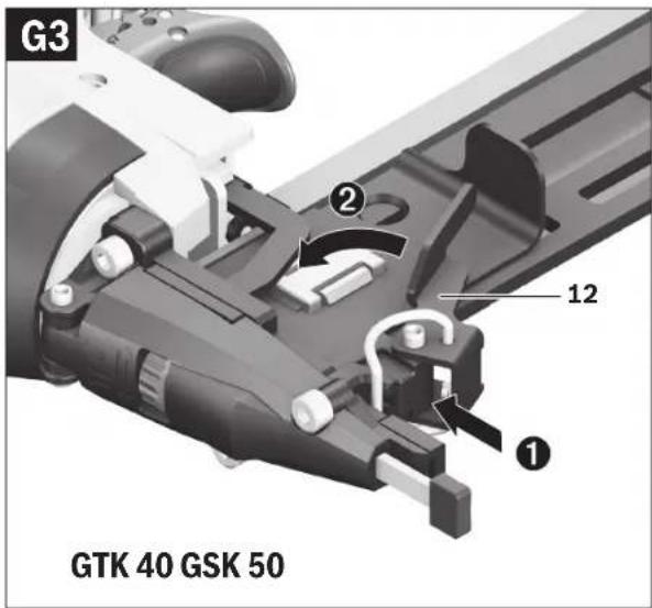
natural_image
Mechanical assembly diagram showing a lever mechanism with labeled component '21' and directional arrow (no readable text or symbols beyond label)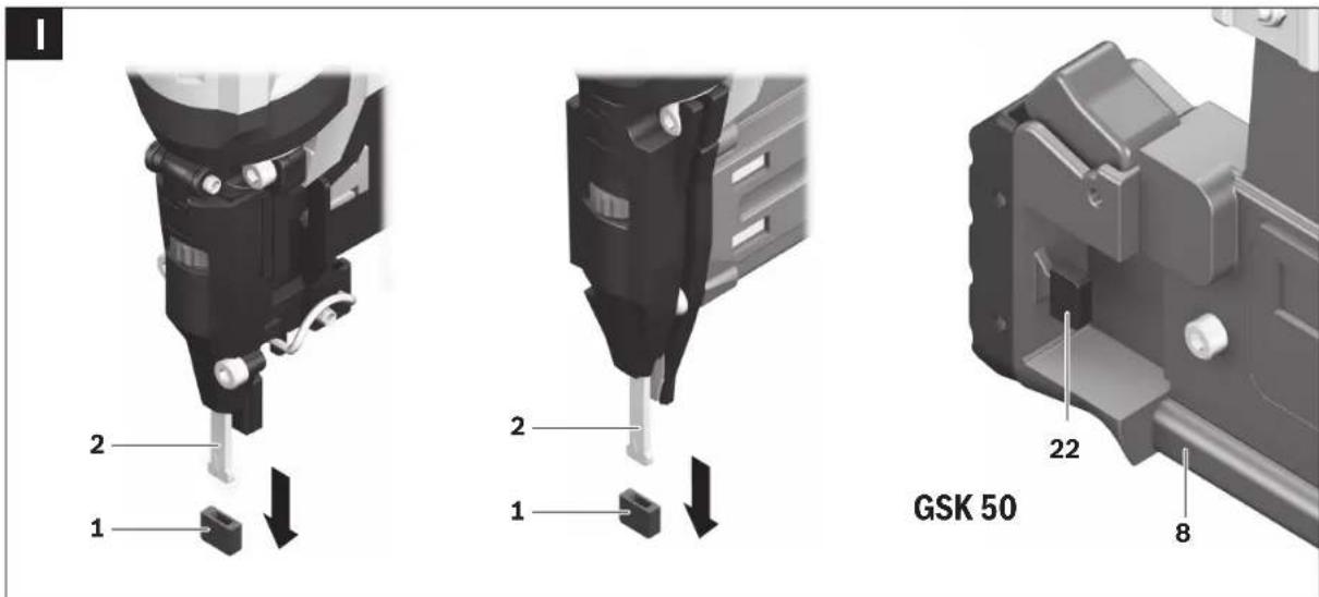
1 609 92A 10X | (11.11.14) Bosch Power Tools
natural_image
Mechanical component diagram showing a drill bit with labeled part 6 (no text or symbols beyond label)8 | Deutsch
Deutsch
Sicherheitshinweise
Executive Vice President Engineering
Helmut Heinzelmann
Head of Product Certification PT/ETM9

i.v. h:m
Robert Bosch GmbH, Power Tools Division
70764 Leinfelden-Echterdingen, GERMANY
General Safety Rules for Pneumatic Tools
WARNING
Before installing, operating, repairing, maintaining and replacing ac-
cessories as well as prior to working near by the pneumatic tool, please read and observe all instructions.
Failure to follow the following safety warnings may result in serious injury.
Save all safety warnings and instructions for future reference, and make them available to the operator.
Work area safety
Pay attention to surfaces that may have become slippery from using the machine, and to tripping hazards from the pneumatic or hydraulic hose. Slipping, tripping and falling are main reasons for workplace injuries.
Do not operate the pneumatic tool in explosive atmospheres, such as in the presence of flammable liquids, gases or dusts. While working the workpiece, sparks can be created which may ignite the dust or fumes.
▶ Keep children and bystanders away from your workplace while operating the pneumatic tool. Distractions from other persons can cause you to lose control over the pneumatic tool.
Pneumatic tool safety
▶ Never direct the airflow against yourself or other persons close by, and conduct cold air away from your hands. Compressed air can lead to serious injuries.
▶ Check the connections and the air supply lines. All maintenance units, couplers, and hoses should conform to the product specifications in terms of pressure and air volume. Too low pressure impairs the function of the pneumatic tool; too high pressure can result in material damage and personal injury.
▶ Protect the hoses from kinks, restrictions, solvents, and sharp edges. Keep the hoses away from heat, oil, and rotating parts. Immediately replace a damaged hose. A defective air supply line may result in a wild compressed-air hose and can cause personal injury. Raised dust or chips may cause serious eye injury.
▶ Make sure that hose clamps are always tightened firmly. Loose or damaged hose clamps may result in uncontrolled air escape.
Personal safety
Stay alert, watch what you are doing, and use common sense when operating a pneumatic tool. Do not use a pneumatic tool while tired or under the influence of drugs, alcohol, or medication. A moment of inattention while operating a pneumatic tool may result in personal injury.
▶ Use personal protective equipment. Always wear eye protection. Wearing personal protective equipment – such as a respirator, non-skid safety shoes, hard hat or hearing protection – according to the instructions of your employer or as required by the provisions for work and health protection, reduces the risk of personal injury.
▶ Prevent unintentional starting. Make sure that the pneumatic tool is switched off before connecting it to the air supply, picking it up or carrying it. When your finger is on the On/Off switch while carrying the pneumatic tool or when connecting the pneumatic tool to the air supply while it is switched on, accidents can occur.
Remove any adjustment tools before switching on the pneumatic tool. A wrench or key left attached to a rotating part of a pneumatic tool may result in personal injury.
▶ Do not overreach. Keep proper footing and balance at all times. This enables better control of the pneumatic tool in unexpected situations.
▶ Dress properly. Do not wear loose clothing or jewellery. Keep your hair, clothing and gloves away from moving parts. Loose clothes, jewellery or long hair can be caught in moving parts.
If devices are provided for the connection of dust extraction and collection facilities, ensure these are connected and properly used. Use of dust collection can reduce dust-related hazards.
▶ Do not directly inhale the exhaust air. Avoid exposing the eyes to exhaust air. The pneumatic tool's exhaust air can contain water, oil, metal particles and debris from the compressor. This can cause damage to one's health.
Pneumatic tool use and care
▶ Use the clamping devices or a vice to secure and support the workpiece. Holding the workpiece by hand or against your body will not allow for safe operation of the pneumatic tool.
▶ Do not overload the pneumatic tool. Use the pneumatic tool intended for your work. The correct pneumatic tool will do the job better and safer at the rate for which it is designed.
Do not use a pneumatic tool that has a defective On/Off switch. A pneumatic tool that cannot be controlled with the switch is dangerous and must be repaired.
▶ Disconnect the air supply before making any adjustments, changing accessories, or when not using for extended periods. This safety measure prevents accidental starting of the pneumatic tool.
▶ Store idle pneumatic tools out of the reach of children. Do not allow persons unfamiliar with the pneumatic tool or these instructions to operate the device. Pneumatic tools are dangerous in the hands of untrained users.
Maintain the pneumatic tool with care. Check for misalignment or binding of moving parts, breakage of parts and any other condition that may affect the pneumatic tool's operation. Have damaged parts repaired before using the pneumatic tool. Many accidents are caused by poorly maintained pneumatic tools.
▶ Keep cutting tools sharp and clean. Properly maintained cutting tools with sharp cutting edges are less likely to bind and are easier to control.
▶ Use the pneumatic tool, accessories, application tools, etc. according to these instructions. Take into consideration the working conditions and the activities to be carried out. This reduces the development of dust, vibrations and noise to the greatest extent.
The pneumatic tool should be set up, adjusted or used exclusively by qualified and trained operators.
The pneumatic tool may not be modified in any way. Modifications can reduce the effectivity of the safety measures and increase the risks for the operator.
Service
▶ Have your pneumatic tool repaired only through a qualified repair person and only using original replacement parts. This will ensure that the safety of the pneumatic tool is maintained.
Safety Warnings for Compressed-air Nailers/Staplers

Wear safety goggles.
▶ Always assume that the pneumatic tool is loaded with fasteners. Careless handling of the pneumatic tool can lead to unexpected shot actuation of fasteners and cause injury.
When working, hold the pneumatic tool in such a manner that your head and body cannot be injured in case of sudden kickback due to a malfunction of the energy supply or from hard objects/locations in the workpiece.
▶ Never point the pneumatic tool at yourself or at persons close by. Unexpected actuation will expel a fastener, which can lead to injury.
▶ Do not actuate the pneumatic tool until firmly placed against the workpiece. When the pneumatic tool is not in contact with the workpiece, the fastener can bounce away from the fastening point and overload the pneumatic tool.

Do not work on ladders or scaffolds when the actuation system "Contact actuation" is set. In particular, do not move from one fastening location to another, close boxes or enclosures, or fasten
transport-securing fixtures on e.g., vehicles and wagons, via scaffolds, stairs, ladders or ladder-like constructions, such as roof battens. With this actuation system, a fastener will be discharged each time when accidentally applying the pneumatic tool while the discharge lock-off is pressed in. This can lead to injury.
▶ Observe the conditions of the job site. It is possible that fasteners can burst through thin workpieces or be deflected when working in corners or against edges, and harm persons.

Disconnect the air supply, when the fastener is jammed in the pneumatic tool. When the pneumatic tool is still connected to the power supply, it can accidentally be actuated when removing a jammed fastener.
▶ Use caution when removing a jammed or stuck fastener. The system can be under tension and cause the fastener to be shot or thrust out, while attempting to clear the jam.
14 | English
Do not use this to pneumatic tool to fasten electrical wiring. It is not suitable for fastening electrical wiring, can damage the insulation of electric cables and thus lead to electric shock and danger of fire.
▶ Never use oxygen or flammable gases as the energy source for the pneumatic tool. Flammable gases are dangerous and can cause the pneumatic tool to explode.
▶ Use appropriate detectors to determine if utility lines are hidden in the work area or call the local utility company for assistance. Contact with electric lines can lead to fire and electric shock. Damaging a gas line can lead to explosion. Penetrating a water line causes property damage.
The pneumatic tool may only be connected to lines, for which the maximal permissible pressure of the pneumatic tool cannot be exceeded by more than 10%; for higher pressures, a pressure control valve (pressure reducer) with preceding pressure-limitation valve in the compressed-air line must be installed. Excessive pressure leads to abnormal operation or breakage of the pneumatic tool, which can lead to injury.
Product Description and Specifications

Read all safety warnings and all instructions. Failure to follow the warnings and instructions may result in electric shock, fire and/or serious injury.
Intended Use
The pneumatic tool is intended for connecting work in roofing, encasing, battening, manufacturing wall and ceiling elements, wood facades, pallets, wood fences, noise-reduction walls and boxes.
Only the fasteners (nails, staples, etc.) specified in table "Technical Data" may be used.
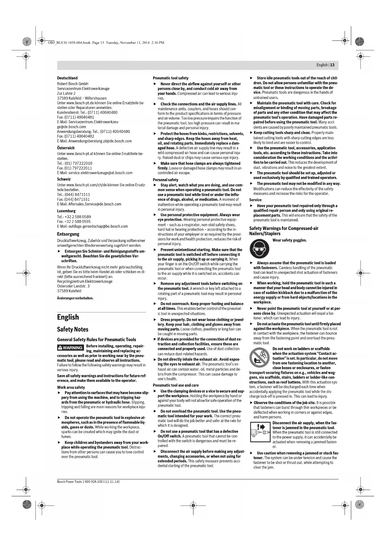
Product Features
The numbering of the product features refers to the illustration of the pneumatic tool on the graphics page.
1 Workpiece protector
2 Discharge lock-off
3 Thumbwheel for depth stop adjustment
4 Air outlet with adjustable exhaust cap
5 Handle
6 Air connector
7 Magazine-slider lock (GTK 40)
8 Magazine
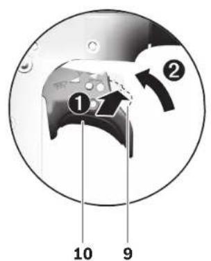
9 Selector switch for actuation system
10 Trigger
11 Magazine slider (GTK 40)
12 Clamping lever for opening/closing the shot duct (GTK 40)
13 Outlet
14 Magazine lock (GSK 50)
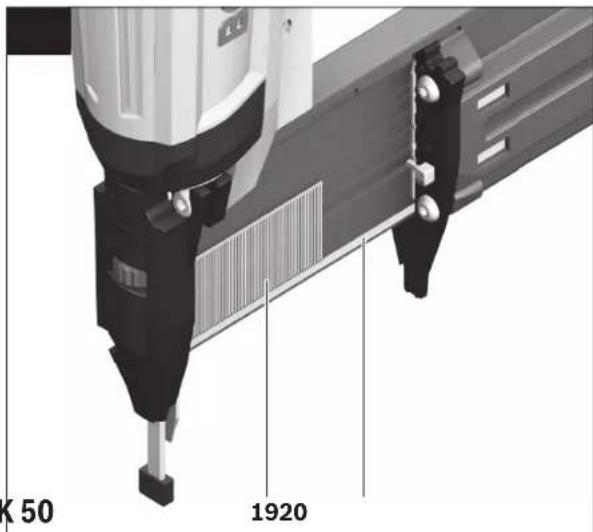
15 Refill indicator (GSK 50)
16 Air-connection coupling
17 Supply-air hose
18 Staple strip*
19 Nail strip*
20 Magazine rail (GSK 50)
21 Driver blade
22 Storage for workpiece protector
*Accessories shown or described are not part of the standard delivery scope of the product. A complete overview of accessories can be found in our accessories program.
Technical Data
| Compressed-air nailer | GTK 40 | GSK 50 | |
| Article number | 3601 D91 G.. 3601 D91 D.. | ||
| Driving force at 6.3 bar (91 psi) | Nm 18.4 17.8 | ||
| Actuation systems | |||
| - Single actuation with safety run | ● | ● | |
| - Contact actuation | ● | ● | |
| Fastener | |||
| - Type | Staple strip | Nail stripBrads | |
| - Length | mm | 13-40 | 15, 19, 25, 30, 35, 40, 45, 50 |
| - Diameter | mm | 1,2 | 1,2 |
| Magazine capacity, max. | 100 | 100 | |
| Engine oil SAE 10, SAE 20 | ml | 0.25-0.5 | 0.25-0.5 |
| Internal volume | ml | 196.5 | 200 |
| Max. working pressure | bar 5-8 | 5-8 | |
| Connecting thread | " | 14 | 14 |
| Supply-air hose | |||
| - Max. operating pressure at 20 °C | bar | 10 | 10 |
| - Inner diameter of hose | " | 14 | 14 |
| - Max. hose length | m | 30 | 30 |
| Air consumption per driving procedure at 6.8 bar (100 psi) | l | 0.71 | 0.69 |
| Dimensions | |||
| - Height | mm | 246 | 251 |
| - Width | mm | 60 | 60 |
| - Length | mm | 272 | 260 |
| Weight according to EPTA-Procedure 01/2003 | kg 1.14 1.14 | ||
Noise/Vibration Information
Sound emission values determined according to EN 12549.
Typically the A-weighted noise levels of the pneumatic tool are: Sound pressure level 96 dB(A); sound power level 110 dB(A). Uncertainty K=3 dB.
Wear hearing protection!
Vibration total values a_h and uncertainty K determined according to EN ISO 20643: a_h<2.5 m/s^2 , K=1.5 m/s^2 .
Declaration of Conformity

We declare under our sole responsibility that the product described under "Technical data" complies with all applicable provisions of the directive 2006/42/EC including its amendments and is in conformity with the following standards: EN 792-13.
Technical file (2006/42/EC) at:
Robert Bosch GmbH, PT/ETM9,
70764 Leinfelden-Echterdingen, GERMANY
Henk Becker
Helmut Heinzelmann
Executive Vice President
Head of Product Certification
Engineering
PT/ETM9


Robert Bosch GmbH, Power Tools Division
70764 Leinfelden-Echterdingen, GERMANY
Connecting the Air Supply (see figure A)
Make sure that the pressure of the compressed-air system is below the maximum permitted rated pressure of the pneumatic tool. Firstly, set the air pressure to the lower value of the recommended rated pressure (see "Technical Data").
When in doubt, check the pressure at the air inlet with a pressure gauge with the pneumatic tool switched on.
For maximum performance, the values for the supply-air hose 17 (connection thread, maximum operating pressure, inner hose diameter, maximum hose length; see "Technical Data") must be observed.
The compressed air supplied should be free of foreign material and moisture to protect the tool from damage, contamination, and the formation of rust.
All fittings, connecting lines and hoses must be dimensioned for the pressure and the required air volume.
Avoid restrictions in the air supply, e.g., from pinching, kinking, or stretching!
English | 15
Connecting the Air Supply to the Pneumatic Tool
- Empty the magazine 8. (See "Emptying the Magazine", page 15) For the following worksteps, a fastener can be discharged when interior parts of the pneumatic tool are not in the starting position due to repairs, maintenance or transport.
- Connect the air connector 6 with a supply-air hose 17 equipped with an air-connection coupling 16.
- Check the proper function by placing the outlet 13 or the rubber workpiece protector 1 of the pneumatic tool onto a piece of scrap wood or wood material, and discharging once or twice.
Loading the Magazine

Disconnect the air supply before making any adjustments, changing accessories, or placing the pneumatic tool aside. This safety measure prevents accidental starting of the pneumatic tool.
▶ Use only original Bosch accessories (see "Technical Data"). The precision parts of the pneumatic tool such as the magazine, the outlet and the shot duct are matched to Bosch staples, nails and brads. Other manufacturers use other steel qualities and sizes. Using fasteners not permitted, can damage the pneumatic tool and cause injuries.
While loading the magazine, hold the pneumatic tool in such a manner that the outlet 13 is not pointed at your own body or at other persons.
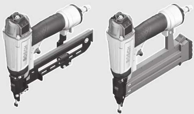
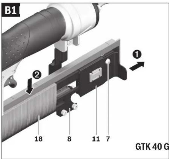
GTK 40 (see figures B1-B2)
– Pull back the magazine slider 11 until the button of magazine-slider lock 7 fully engages.
- Clean and lubricate the magazine slider 11 as required and make sure that the magazine 8 is not dirty/soiled.
- Place a fitting strip of staples 18 over magazine 8. The staple heads must face completely flush against the surface of the magazine and the staple strips must move easily in the magazine.
- Lightly pull back magazine slider 11 and press the button of magazine-slider lock 7 inward.
- Carefully guide the magazine slider to the front until it touches the staple strip.
Note: Do not let the magazine slider snap back without guiding it. Otherwise, the magazine slider could become damaged, and there is danger of your fingers being caught or pinched.
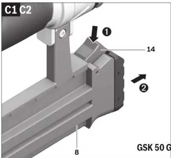
GSK 50 (see figures C1-C2)
- Press magazine lock 14 and at the same time pull magazine 8 toward the rear to the stop.
- Clean and lubricate magazine rail 20 as required.
- Insert a fitting nail strip 19.
If possible, the nail tip should touch the magazine rail 20.
- Slide the nail strip in the magazine all the way to the front.
- Insert the magazine until magazine lock 14 engages again.
Refill the magazine when the red bars of refill indicator 15 can be seen halfway.
Operation
Actuation systems
The pneumatic tool can be operated with two different actuations systems:
Single actuation with safety run
With this actuation system, the discharge lock-off 2 must first be firmly pressed against the workpiece. A fastener is not discharged until the trigger 10 is pulled. Afterwards, further discharging procedures can only be actuated, when the trigger and the discharge lock-off have first been set back to the starting position.
Contact actuation
With this actuation system, the trigger 10 must be pulled first. A fastener is always discharged when the discharge lock-off 2 is firmly pressed against the workpiece while the trigger is pressed.
This enables a higher working speed to be achieved.
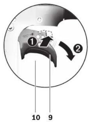
The actuation system is set via the selector switch 9.
Starting Operation

Disconnect the air supply before making any adjustments, changing accessories, or placing the pneumatic tool aside. This safety measure prevents accidental starting of the pneumatic tool.
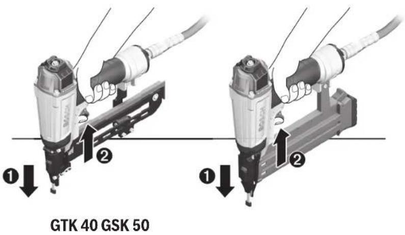
Working with Single Actuation (see figure D)
- Press selector switch 9 inward and at the same time pivot it to the bottom position until it engages.
The actuation system "single actuation" is set.
- Release the selector switch 9 again.
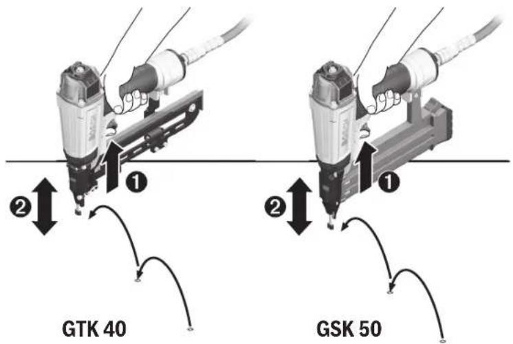
- Firmly position the outlet 13 or the rubber workpiece protector 1 on the workpiece until discharge lock-off 2 is pressed in completely.
- Afterwards, briefly press trigger 10 and release again. A staple (GTK 40) or a brad (GSK 50) is discharged.
- Allow the pneumatic tool to bounce back from the workpiece.
- For another driving procedure, completely lift the pneumatic tool from the workpiece and position it firmly at the next desired location.
Working with Contact Actuation (see figure E)
- Press selector switch 9 inward and at the same time pivot it to the upper position until it engages.
The actuation system "contact actuation" is set.
- Release the selector switch 9 again.
- Press and hold the trigger 10.
- Firmly position the outlet 13 or the rubber workpiece protector 1 on the workpiece until discharge lock-off 2 is pressed in completely.
A staple (GTK 40) or a brad (GSK 50) is discharged. - Allow the pneumatic tool to bounce back from the workpiece.
- For another driving procedure, completely lift the pneumatic tool from the workpiece and position it firmly at the next desired location.
- Move the pneumatic tool uniformly over the workpiece by lifting it off and applying it again. Each time when applying the pneumatic tool while the discharge lock-off is pressed in, a staple (GTK 40) or a brad (GSK 50) is discharged.
- As soon as the desired amount of staples (GTK 40) or brads (GSK 50) have been driven in, release trigger 10 again.
Working Advice

Disconnect the air supply before making any adjustments, changing accessories, or placing the pneumatic tool aside. This safety measure prevents accidental starting of the pneumatic tool.
Check the proper function of the safety and actuation devices, and the tight seating of all screws and nuts each time before using.
Disconnect a defective or not properly operating pneumatic tool immediately from of the air supply and contact an authorised service agent for Bosch power tools.
Do not perform any incorrect manipulations on the pneumatic tool. Do not disassemble or block any components of the pneumatic tool, such as the discharge lock-off.
Do not carry out "emergency repairs" with unsuitable means. The pneumatic tool is to be maintained regularly and properly (see "Maintenance and Cleaning", page 16).
Avoid any weakening and damage whatsoever of the pneumatic tool, e.g., through:
- Imprinting or engraving,
– Retrofitting measures not approved by the manufacturer.
– Guiding along templates manufactured of hard material, e.g. steel.
- Dropping on or sliding over the floor,
- Using as a hammer.
- Applying any kind of force.
Make sure to check whatever is below or behind your workpiece. Do not shoot staples (GTK 40) or brads (GSK 50) into walls, ceilings or floors, when persons are behind them. The fasteners can burst through the workpiece and injure someone.
Do not shoot a staple (GTK 40) or brad (GSK 50) on already driven-in fasteners. This could cause the fastener to deform, the fasteners could become jammed or the pneumatic tool could move uncontrolled.
When the pneumatic tool is used under cold ambient conditions, the first staples (GTK 40) or brads (GSK50) are driven in slower than usual. Once the pneumatic tool has warmed up during working, normal operating speed will be regained.
Avoid blank shots in order to reduce the wear of the impact striker.
For longer work breaks or after finishing work, disconnect the pneumatic tool from the air supply and empty the magazine.
Emptying the Magazine
GTK 40
- Pull back the magazine slider 11 until the button of magazine-slider lock 7 fully engages.
- Remove staple strip 18.
- Lightly pull back magazine slider 11 and press the button of magazine-slider lock 7 inward.
- Carefully guide the magazine slider to the front until it touches the beginning of the magazine.
Note: Do not let the magazine slider snap back without guiding it. Otherwise, the magazine slider could become damaged, and there is danger of your fingers being caught or pinched.
GSK 50
- Press magazine lock 14 and at the same time pull magazine 8 toward the rear to the stop.
- Remove the nail strips 19.
- Insert the magazine until magazine lock 14 engages again.
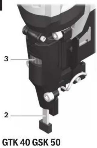
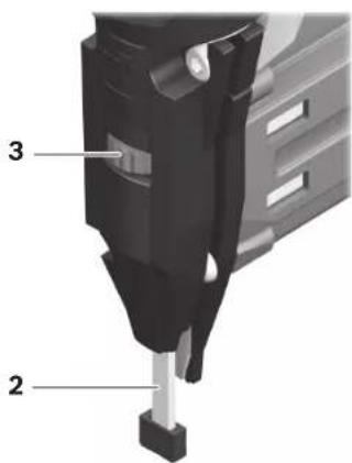
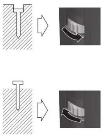
Adjusting the Depth Stop (see figure F)
The driving depth of the staples (GTK 40) or brads (GSK 50) can be set with thumbwheel 3.
- Empty the magazine 8. (See "Emptying the Magazine", page 15)
- Nails are driven in too deeply:
To reduce the driving depth, turn thumbwheel 3 in anticlockwise direction.
or
Nails are not driven in deep enough:
To increase the driving depth, turn thumbwheel 3 in clockwise direction.
- Refill the magazine.
(See "Loading the Magazine", page 15) - Test the new driving depth on a test workpiece. Repeat the worksteps as required.
Clearing Jams
Single staples (GTK 40) or brads (GSK 50) can become jammed in the shot duct. If this should occur frequently, please contact an authorised service agent for Bosch power tools.
Note: When the driver blade does not return after clearing a jam, please contact an authorised service agent for Bosch power tools.
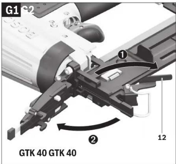
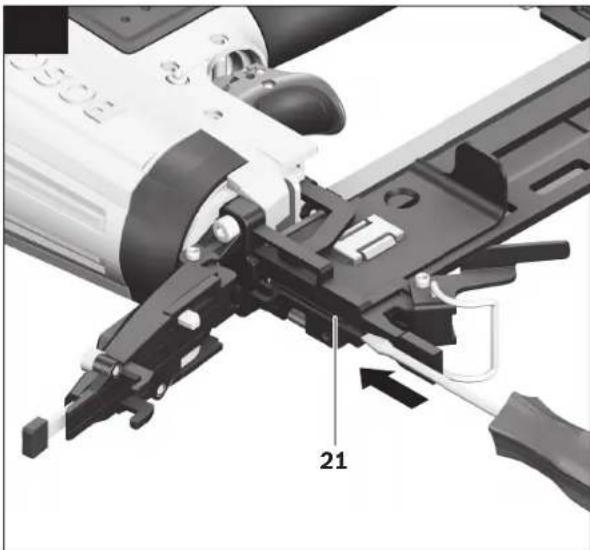
GTK 40 (see figures G1-G3)
- Empty the magazine 8. (See "Emptying the Magazine", page 15)
- Press clamping lever 12 down so that the shot duct opens.
- Remove the jammed staple. For this, use a pair of pliers, if required.
- When driver blade 21 is extended, push it back into the piston using a lubricated screwdriver or other suitable lubricated object.
- Lubricate the shot duct with 2–3 drops of engine oil (SAE 10 or SAE 20).
- Close the shot duct, hang the clip of clamping lever 12 into the hooks on the shot duct and then push the clamping lever up again.
- Refill the magazine.
(See "Loading the Magazine", page 15)
16 | English
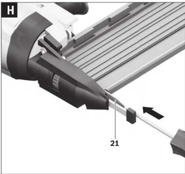
GSK 50 (see figure H)
- Empty the magazine 8.
(See "Emptying the Magazine", page 15) - With the magazine open, re this, us a pair of pliers, if required.
- When driver blade 21 is extended, push it back into the piston using a lubricated screwdriver or other suitable lubricated object.
- Lubricate the shot duct with 2–3 drops of engine oil (SAE 10 or SAE 20).
- Refill the magazine. (See "Loading the Magazine", page 15)
Changing the Workpiece Protector (see figure I)
The workpiece protector 1 at the end of the discharge lock-off 2 protects the workpiece until the pneumatic tool is cor- move the finned bodying procedure.
The workpiece protector can be removed and replaced.
– Pull the workpiece protector from the discharge lock-off.
- Push the new workpiece protector via the open end over the discharge lock-off.
GSK 50: This pneumatic tool allows for a spare workpiece protector to be stored at the top side of magazine 8. For this, push the workpiece protector into the depot 22.
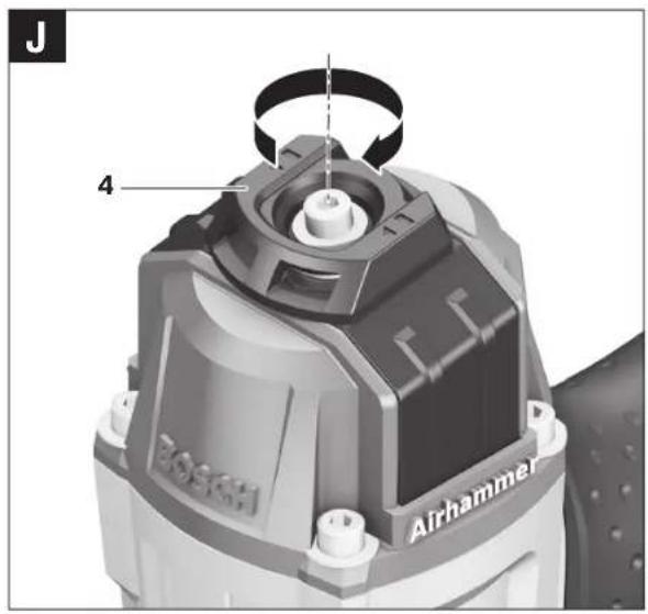
Adjustable Air-outlet cap (see figure J)
With the adjustable exhaust cap at the air outlet 4, it is possible to deflect the exhaust air away from yourself or the workpiece.
Transport and Storage
For transport, disconnect the pneumatic tool from the air supply; especially when using ladders or moving in an unusual stance or posture.
At the workplace, carry the pneumatic tool only by the handle 5 and with the trigger 10 released.
Always store the pneumatic tool disconnected from the air supply and at a clean and dry location.
When not using the pneumatic tool for a longer period of time, cover steel parts with a fine oil coating. This prevents the formation of rust.
Maintenance and Service
Maintenance and Cleaning

Disconnect the air supply before making any adjustments, changing accessories, or placing the pneumatic tool aside. This safety measure prevents accidental starting of the pneumatic tool.
▶ Have maintenance and repair work carried out only through qualified persons. This will ensure that the safety of the pneumatic tool is maintained.
An authorized Bosch after-sales service agent will carry out this work quickly and reliably.
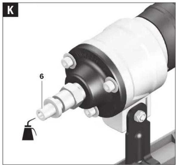
Lubricating the Pneumatic Tool (see figure K)
When the pneumatic tool is not connected to a maintenance unit, it must be lubricated at regular intervals:
- For light-duty use 1x per day.
- For heavy-duty use 2x per day.
Apply 2–3 drops of lubricant into air connector 6. Do not apply too much lubricant, which could then accumulate in the pneumatic tool and be emitted via air outlet 4.
Use only the lubricants recommended by Bosch.
- SAE 10 mineral engine oil (for use at very cold ambient conditions)
- SAE 20 mineral engine oil
▶ Observe all applicable environmental regulations when disposing of old grease and solvents.
Maintenance Schedule
Always keep air outlet 4, discharge lock-off 2 and trigger 10 clean and free of foreign material (dust, chips, sand, etc).
Clean the magazine 8. Remove any plastic or wood chips that may accumulate in the magazine during operation.
Clean the pneumatic tool in regular intervals using compressed air.
Measure Explanation Action
| Draining the exhaust filter daily. | Prevents the accumulation of dirt/ debris and moisture in the pneumatic tool. | - Open the drain valve. |
| Keeping the lubricator filled at all times. | Ensures the lubrication of the pneumatic tool. | - Fill lubricator with the recommended lubricants.(See “Lubricating the Pneumatic Tool”, page 16) |
| Cleaning the magazine 8 and magazine slider 11. | Prevents a staple (GTK 40) or brad (GSK 50) from becoming jammed. | - Blow out the mechanism of the magazine/magazine slider daily with compressed air. |
| Ensuring that the discharge lock-off 2 functions properly. | Promotes your work safety and efficient usage of the pneumatic tool. | - Blow out the mechanism of the discharge lock-off daily with compressed air. |
| Lubricating the pneumatic tool. | Reduces the wear of the pneumatic tool. | - Apply 2–3 drops of lubricant into air connector 6.(See “Lubricating the Pneumatic Tool”, page 16) |
| Draining the compressor. | Prevents the accumulation of dirt/ debris and moisture in the pneumatic tool. | - Open the drain valve of the compressor tank. |
Correction of Malfunctions
| Problem Cause | Corrective Measure | |
| The pneumatic tool is ready for operation, but no staples (GTK 40) or brads (GSK 50) are discharged. | A staple (GTK 40) or a brad (GSK 50) has become jammed in the shot duct. | - Clear the jam.(See “Clearing Jams”, page 15) |
| The magazine slider is 11 defective. | - Clean and lubricate the magazine slider 11 as required and make sure that the magazine 8 is not dirty/soiled. | |
| The spring of the magazine slider is too week or defective. | - Contact an authorised service agent for Bosch power tools.Have the component replaced there. | |
| The fasteners being used are not permitted. - Use only original accessories. | Only the fasteners (nails, staples, etc.) specified in table “Technical Data” may be used. | |
| The magazine 8 is empty. | - Refill the magazine.(See “Loading the Magazine”, page 15) | |
| The staples (GTK 40) or brads (GSK 50) are discharged very slowly and with too little pressure. | The rated pressure of the compressed-air supply is too low. | - Increase the compressed-air supply. 8 bar may not be exceeded. |
| The driver blade is damaged. | - Use only the lubricants recommended by Bosch.(See “Lubricating the Pneumatic Tool”, page 16) | |
| The sealing ring of the piston is worn or damaged. | - Contact an authorised service agent for Bosch power tools.Have the component replaced there. | |
| The buffer is worn. | - Contact an authorised service agent for Bosch power tools.Have the component replaced there. | |
| The length and diameter of supply-air hose 17 do not correspond with the data of this pneumatic tool. | - Use a supply-air hose with the correct dimensions.(See “Technical Data”, page 14) | |
| The supply-air hose 17 is bent/creased. | - Correct the bend/crease in the supply-air hose. | |
Français | 17
| Problem | Cause | Corrective Measure |
| The staples (GTK 40) or brads (GSK 50) are driven in too deep. | The rated pressure of the compressed-air supply is too high. | - Reduce the compressed-air supply. 5 bar may not be fallen below. |
| The depth stop is set too deep. - Adjust the depth stop to the desired depth.(See "Adjusting the Depth Stop", page 15) | ||
| The buffer is worn. - Contact an authorised service agent for Bosch power tools.Have the component replaced there. | ||
| The staples (GTK 40) or brads (GSK 50) are not driven in deep enough. | The rated pressure of the compressed-air supply is too low. | - Increase the compressed-air supply. 8 bar may not be exceeded. |
| The depth stop is set too high. - Adjust the depth stop to the desired depth.(See "Adjusting the Depth Stop", page 15) | ||
| The length and diameter of supply-air hose 17 do not correspond with the data of this pneumatic tool. | - Use a supply-air hose with the correct dimensions.(See "Technical Data", page 14) | |
| The supply-air hose 17 is bent/creased. | - Correct the bend/crease in the supply-air hose. | |
| The pneumatic tool skips staples (GTK 40) or brads (GSK 50) or has a too large cycle feed. | The fasteners being used are not permitted. - Use only original accessories.Only the fasteners (nails, staples, etc.) specified in table "Technical Data" may be used. | |
| The magazine 8 is not operating correctly. | - Clean and lubricate the magazine slider 11 as required and make sure that the magazine 8 is not dirty/soiled. | |
| The spring of the magazine slider is too week or defective. | - Contact an authorised service agent for Bosch power tools.Have the component replaced there. | |
| The sealing ring of the piston is worn or damaged. | - Contact an authorised service agent for Bosch power tools.Have the component replaced there. | |
| The staples (GTK 40) or brads (GSK 50) frequently jam in the shot duct. | The fasteners being used are not permitted. - Use only original accessories.Only the fasteners (nails, staples, etc.) specified in table "Technical Data" may be used. | |
| - Contact an authorised service agent for Bosch power tools. | ||
| The driven staples (GTK 40) or brads (GSK 50) are bent. | The driver blade is damaged. | - Contact an authorised service agent for Bosch power tools.Have the component replaced there. |
| Contrary to working with normal operating speed, the staples (GTK 40) or brads (GSK 50) are not driven in deep enough enough at higher operating speeds. | The interior diameter of the supply-air hose is too low. | - Use a supply-air hose with the correct dimensions.(See "Technical Data", page 14) |
| The compressor is not suitable for fast operating speeds. | - Use a compressor that is sufficiently dimensioned for the number of connected pneumatic tools and the operating speed. | |
Accessories
For more information on the complete quality accessories program, please refer to the Internet under www.bosch-pt.com or contact your specialist shop.
After-sales Service and Application Service
Our after-sales service responds to your questions concerning maintenance and repair of your product as well as spare parts. Exploded views and information on spare parts can also be found under:
www.bosch-pt.com
Bosch's application service team will gladly answer questions concerning our products and their accessories. In all correspondence and spare parts orders, please always include the 10-digit article number given on the type plate of the pneumatic tool.
Great Britain
Robert Bosch Ltd. (B.S.C.)
P.O. Box 98
Broadwater Park
North Orbital Road
Denham
Uxbridge
UB 9 5HJ
At www.bosch-pt.co.uk you can order spare parts or arrange the collection of a product in need of servicing or repair.
Tel. Service: (0344) 7360109
E-Mail: boschservicecentre@bosch.com
Ireland
Origo Ltd.
Unit 23 Magna Drive
Magna Business Park
City West
Dublin 24
Tel. Service: (01) 4666700
Fax: (01) 4666888
Australia, New Zealand and Pacific Islands
Robert Bosch Australia Pty. Ltd.
Power Tools
Locked Bag 66
Clayton South VIC 3169
Customer Contact Center
Inside Australia:
Phone: (01300) 307044
Fax: (01300) 307045
Inside New Zealand:
Phone: (0800) 543353
Fax: (0800) 428570
Outside AU and NZ:
Phone: +61 3 95415555
www.bosch.com.au
Republic of South Africa
Customer service
Hotline: (011) 6519600
Gauteng - BSC Service Centre
35 Roper Street, New Centre
Johannesburg
Tel.: (011) 4939375
Fax: (011) 493012
E-Mail: bsctools@icon.co.za
KZN - BSC Service Centre
Unit E, Almar Centre
143 Crompton Street
Pinetown
Tel.: (031) 7012120
Fax: (031) 7012446
E-Mail: bsc.dur@za.bosch.com
Western Cape - BSC Service Centre
Democracy Way, Prosperity Park
Milnerton
Tel.: (021) 5512577
Fax: (021) 5513223
E-Mail: bsc@zsd.co.za
Bosch Headquarters
Midrand, Gauteng
Tel.: (011) 6519600
Fax: (011) 6519880
E-Mail: rbsa-hq.pts@za.bosch.com
Disposal
The pneumatic tool, accessories and packaging should be sorted for environmental-friendly recycling.
▶ Observe all applicable environmental regulations when disposing of old grease and solvents.
If your pneumatic tool can no longer be used, deliver it to a recycling centre or return it to a dealer – for example, an authorized Bosch after-sales service agent.
Subject to change without notice.
Français
Executive Vice President
Engineering
Helmut Heinzelmann
Head of Product Certification
PT/ETM9
PPa
jus Bo i.v. h:m
Robert Bosch GmbH, Power Tools Division
70764 Leinfelden-Echterdingen, GERMANY
Robert Bosch (France) S.A.S.
Executive Vice President
Engineering
Helmut Heinzelmann
Head of Product Certification
PT/ETM9
^a

i.v. h=mc
Robert Bosch GmbH, Power Tools Division
70764 Leinfelden-Echterdingen, GERMANY
Henk Becker Executive Vice President Engineering Helmut Heinzelmann Head of Product Certification PT/ETM9

Robert Bosch GmbH, Power Tools Division 70764 Leinfelden-Echterdingen, GERMANY Leinfelden, 13.11.2014
Dados técnicos
Executive Vice President
Engineering
Helmut Heinzelmann
Head of Product Certification
PT/ETM9

Robert Bosch GmbH, Power Tools Division
70764 Leinfelden-Echterdingen, GERMANY
Executive Vice President
Head of Product Certification
Engineering
PT/ETM9


Robert Bosch GmbH, Power Tools Division
70764 Leinfelden-Echterdingen, GERMANY
Executive Vice President
Head of Product Certification
Engineering
PT/ETM9


Robert Bosch GmbH, Power Tools Division 70764 Leinfelden-Echterdingen, GERMANY
Bosch Service Center
Telegrafvej 3
2750 Ballerup
På www.bosch-pt.dk kan der online bestilles reservedele eller oprettes en reparations ordre.
Tlf. Service Center: 44898855
Fax: 44898755
E-Mail: vaerktoej@dk.bosch.com
Bortskaffelse
Executive Vice President
Head of Product Certification
Engineering
PT/ETM9


Robert Bosch GmbH, Power Tools Division
70764 Leinfelden-Echterdingen, GERMANY
Executive Vice President
Engineering
Helmut Heinzelmann
Head of Product Certification
PT/ETM9
PPa
Robert Bosch GmbH, Power Tools Division
70764 Leinfelden-Echterdingen, GERMANY
Executive Vice President
Engineering
Helmut Heinzelmann
Head of Product Certification
PT/ETM9

Robert Bosch GmbH, Power Tools Division 70764 Leinfelden-Echterdingen, GERMANY Leinfelden, 13.11.2014
Asennus
Executive Vice President
Engineering
Helmut Heinzelmann
Head of Product Certification
PT/ETM9


Robert Bosch GmbH, Power Tools Division
70764 Leinfelden-Echterdingen, GERMANY Leinfelden, 13.11.2014
Συναρμολόγηση
Henk Becker Executive Vice President Engineering Helmut Heinzelmann Head of Product Certification PT/ETM9

Robert Bosch GmbH, Power Tools Division 70764 Leinfelden-Echterdingen, GERMANY Leinfelden, 13.11.2014
Türkçe|67
Teknik veriler
Henk Becker Executive Vice President Engineering Helmut Heinzelmann Head of Product Certification PT/ETM9

Robert Bosch GmbH, Power Tools Division 70764 Leinfelden-Echterdingen, GERMANY Leinfelden, 13.11.2014
Dane techniczne
Robert Bosch Sp. z o.o.
Executive Vice President Engineering
Helmut Heinzelmann
Head of Product Certification PT/ETM9
Ppa
if we see i.v. h.w.
Robert Bosch GmbH, Power Tools Division 70764 Leinfelden-Echterdingen, GERMANY Leinfelden, 13.11.2014
Bosch Service Center PT
K Vápence 1621/16
692 01 Mikulov
Executive Vice President
Head of Product Certification
Engineering
PT/ETM9

i.v. h·w—
Robert Bosch GmbH, Power Tools Division
70764 Leinfelden-Echterdingen, GERMANY
Executive Vice President
Engineering
Helmut Heinzelmann
Head of Product Certification
PT/ETM9

Robert Bosch GmbH, Power Tools Division
70764 Leinfelden-Echterdingen, GERMANY
Executive Vice President
Engineering
Helmut Heinzelmann
Head of Product Certification PT/ETM9
PPa

i.v. h=mc
Robert Bosch GmbH, Power Tools Division
70764 Leinfelden-Echterdingen, GERMANY
Henk Becker Executive Vice President Engineering Helmut Heinzelmann Head of Product Certification PT/ETM9

Robert Bosch GmbH, Power Tools Division 70764 Leinfelden-Echterdingen, GERMANY Leinfelden, 13.11.2014
Технічні дані
Executive Vice President Engineering
Head of Product Certification PT/ETM9

Robert Bosch GmbH, Power Tools Division
70764 Leinfelden-Echterdingen, GERMANY
Executive Vice President
Head of Product Certification
Engineering
PT/ETM9

Robert Bosch GmbH, Power Tools Division 70764 Leinfelden-Echterdingen, GERMANY
Tel. service scule electrice: (021) 4057540
Fax: (021) 4057566
E-Mail: infoBSC@ro.bosch.com
Executive Vice President Engineering
Helmut Heinzelmann
Head of Product Certification PT/ETM9

Robert Bosch GmbH, Power Tools Division 70764 Leinfelden-Echterdingen, GERMANY Leinfelden, 13.11.2014
Executive Vice President Head of Product Certification Engineering PT/ETM9

Robert Bosch GmbH, Power Tools Division 70764 Leinfelden-Echterdingen, GERMANY Leinfelden, 13.11.2014
118 | Македонски
Технички податоци
Executive Vice President
Engineering
Helmut Heinzelmann
Head of Product Certification
PT/ETM9

Robert Bosch GmbH, Power Tools Division
70764 Leinfelden-Echterdingen, GERMANY
Executive Vice President
Head of Product Certification
Engineering
PT/ETM9

i.v. k-m
Robert Bosch GmbH, Power Tools Division
70764 Leinfelden-Echterdingen, GERMANY Leinfelden, 13.11.2014
Tehnični podatki
| Pnevmatski žebljalnik | GTK 40 | GSK 50 | |
| Številka artikla | 3 6 0 1 D 9 1 G... 3 6 0 1 D 9 1 D.. | ||
| Zabijalna sila pri 6,3 bar (91 psi) | Nm 18,4 17,8 | ||
| Sprožilni sistemi | |||
| - Posamezna sprožitev z varovalom | ● | ● | |
| - S pro ži te v kontakta | ● | ● | |
| Zabijalni predmet | |||
| - Tip | Trak s sponkami | Trak z žebljiŽeblji z ozko glavo | |
| - D o l ž i n a | mm | 13-40 | 15, 19, 25, 30, 35, 40, 45, 50 |
| - P r e m e r | mm | 1,2 | 1,2 |
| maks. kapaciteta vlagalnika | 100 | 100 | |
| Motorno olje SAE 10, SAE 20 | ml | 0,25-0,5 | 0,25-0,5 |
| Notranji volumen | ml | 196,5 | 200 |
| maks. delovni tlak | bar | 5-8 | 5-8 |
| Priključni navoj | " | 14 | 14 |
| Dovodna gibka cev | |||
| - Maksimalni delovni tlak pri 20 °C | bar | 10 | 10 |
| - S v e t l i n a c e vi | " | 14 | 14 |
| - Maks. dolžina gibke cevi | m | 30 | 30 |
| Poraba zraka pri postopku zabijanja pri 6,8 bar (100 psi) | l | 0,71 | 0,69 |
| Mere | |||
| - Višina | mm | 246 | 251 |
| - Širina | mm | 60 | 60 |
| - D o l ž i n a | mm | 272 | 260 |
| Teža po EPTA-Procedure 01/2003 | kg 1,14 1,14 | ||
Montaža
Priključek na enoto za oskrbovanje z zrakom (glejte slikoA)
Henk Becker Executive Vice President Engineering
Helmut Heinzelmann Head of Product Certification PT/ETM9

Robert Bosch GmbH, Power Tools Division 70764 Leinfelden-Echterdingen, GERMANY Leinfelden, 13.11.2014
Montaža
Executive Vice President
Head of Product Certification
Engineering
PT/ETM9


Robert Bosch GmbH, Power Tools Division
70764 Leinfelden-Echterdingen, GERMANY
Executive Vice President
Engineering
Helmut Heinzelmann
Head of Product Certification
PT/ETM9


Robert Bosch GmbH, Power Tools Division
70764 Leinfelden-Echterdingen, GERMANY
Executive Vice President
Head of Product Certification
Engineering
PT/ETM9

Robert Basch GmbH, Power Tools Division 70764 Leinfelden-Echterdingen, GERMANY
Confidence Privacy Expected Modelling Without Wages, Meters, and Privacy Privacy
CEpres Arabic Transparency
Senior Vice President Head of Product Certification
Engineering PT/ETM9

Robert Bosch GmbH, Power Tools Division
70764 Leinfelden-Echterdingen, GERMANY
Senior Vice President
Engineering
Helmut Heinzelmann
Head of Product Certification
PT/ETM9
PPa

i.v. h·w—
Robert Bosch GmbH, Power Tools Division
70764 Leinfelden-Echterdingen, GERMANY


- Deutsch
- Sicherheitshinweise
- General Safety Rules for Pneumatic Tools
- WARNING
- Work area safety
- Pneumatic tool safety
- Personal safety
- Pneumatic tool use and care
- Service
- Safety Warnings for Compressed-air Nailers/Staplers
- | English
- Product Description and Specifications
- Intended Use
- Product Features
- Noise/Vibration Information
- Wear hearing protection!
- Declaration of Conformity
- Connecting the Air Supply (see figure A)
- Connecting the Air Supply to the Pneumatic Tool
- Loading the Magazine
- GTK 40 (see figures B1-B2)
- GSK 50 (see figures C1-C2)
- Operation
- Actuation systems
- Single actuation with safety run
- Contact actuation
- Starting Operation
- Working with Single Actuation (see figure D)
- Working with Contact Actuation (see figure E)
- Working Advice
- Emptying the Magazine
- GTK 40
- GSK 50
- Adjusting the Depth Stop (see figure F)
- Nails are not driven in deep enough:
- Clearing Jams
- GTK 40 (see figures G1-G3)
- | English
- GSK 50 (see figure H)
- Changing the Workpiece Protector (see figure I)
- Adjustable Air-outlet cap (see figure J)
- Transport and Storage
- Maintenance and Service
- Maintenance and Cleaning
- Lubricating the Pneumatic Tool (see figure K)
- Maintenance Schedule
- Accessories
- After-sales Service and Application Service
- www.bosch-pt.com
- Great Britain
- Ireland
- Australia, New Zealand and Pacific Islands
- Republic of South Africa
- Customer service
- Gauteng - BSC Service Centre
- KZN - BSC Service Centre
- Western Cape - BSC Service Centre
- Bosch Headquarters
- Disposal
- ▶ Observe all applicable environmental regulations when disposing of old grease and solvents.
- Français
- Bortskaffelse
- Asennus
- Συναρμολόγηση
- Montaža
- Priključek na enoto za oskrbovanje z zrakom (glejte slikoA)
- CEpres Arabic Transparency
Brand : BOSCH
Model : GSK 50 Professional
Category : Stapler