
3900 Silent - Water pump GARDENA - Free user manual and instructions
Find the device manual for free 3900 Silent GARDENA in PDF.
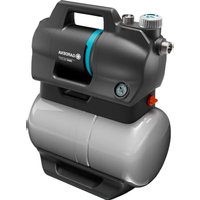


| Product type | Submersible water pump for clear water |
| Brand | Gardena |
| Model | 3900 Silent |
| Dimensions (L x W x H) | 20 x 18 x 35 cm |
| Weight | 6.2 kg |
| Power supply | 230 V ~ 50 Hz |
| Power consumption | 500 W |
| Max flow rate | 6000 l/h |
| Max delivery head | 9 m |
| Max immersion depth | 7 m |
| Max particle size | 5 mm |
| Discharge connection | G1" male |
| Power cable | 10 m |
| Silent technology | Yes |
| Automatic operation | Integrated float switch |
| Dry-run protection | Automatic shut-off |
| Protection class | IP X8 |
| Max water temperature | 35 °C |
| Maintenance | Regular cleaning of the strainer and rotor |
| Spare parts | Seal, strainer, float, cable available |
| Repairability | Repairability index 8.2/10 |
| Warranty | 2 years |
| Country of manufacture | Germany |
Frequently Asked Questions - 3900 Silent GARDENA
User questions about 3900 Silent GARDENA
0 question about this device. Answer the ones you know or ask your own.
Ask a new question about this device
Download the instructions for your Water pump in PDF format for free! Find your manual 3900 Silent - GARDENA and take your electronic device back in hand. On this page are published all the documents necessary for the use of your device. 3900 Silent by GARDENA.
USER MANUAL 3900 Silent GARDENA
3800 Silent Art. 9064
3900 Silent Art. 9066
| de | BetriebsanleitungHauswasserwerk | 4 |
| en | Operator's manualPressure Tank Unit | 9 |
| fr | Manuel d'utilisationGroupe de surpression | 14 |
| bg | ръководство на потребителяХидрофорна уредба | 20 |
| cs | Návod k používáníDomácí vodárna | 25 |
| da | BrugervejledningHusvandværk | 30 |
| el | Εγχειρίδιο χρήσηςΜονάδα αντλίας πίεσης | 35 |
| es | Manual de usuarioEstación de bombeo con calderín eco | 41 |
| et | KasutusjuhendSurvepaagiseade | 46 |
| fi | KäyttöohjePainevesiyksikkö | 51 |
| hr | Upute za uporabuJedinica tlačnog spremnika | 56 |
| hu | Használati útmutatóSilent házi vízmű | 61 |
| it | Manuale dell'operatoreAutoclave | 66 |
| lt | Naudojimo instrukcijaSlėginės talpyklos blokas | 71 |
| lv | Lietotāja rokasgrāmataSpiediena tvertnes bloks | 76 |
| nl | HandleidingHydrofoorpomp | 81 |
| no | BrukermanualTrykktankenhet | 86 |
| pt | Manual do utilizadorBomba de abastecimento doméstico | 91 |
| pl | Instrukcja obsługiZestaw hydroforowy | 96 |
| ro | Manualul operatoruluiUnitate rezervor sub presiune | 101 |
| ru | руководство по эксплуатацииАвтоматическая станцияводоснабжения | 106 |
| sk | Návod na obsluhuDomáca vodáreň | 112 |
| sl | Navodilo za uporaboHišna črpalka | 117 |
| sq | Manual përdorimiBblok depozite uji me presion | 122 |
| sr | Uputstvo Za UpotrebuRezervoar pod pritiskom | 127 |
| sv | BruksanvisningHydroforpump | 132 |
| tr | Kullanım kılavuzuBasınç tankı ünitesi | 137 |
| uk | Інструкція з експлуатаціїНагнітальний пристрій із баком моделі | 142 |
A1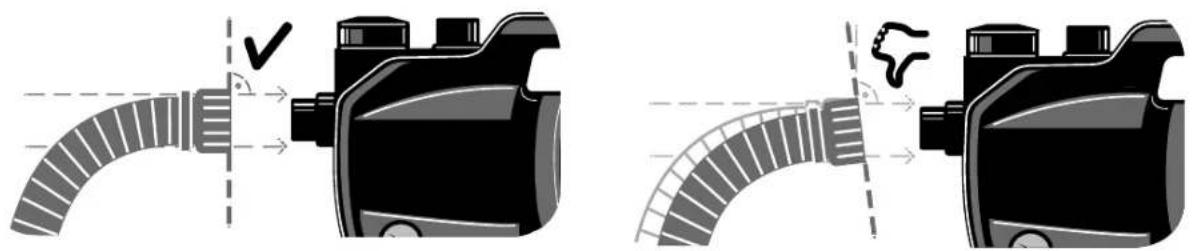
A2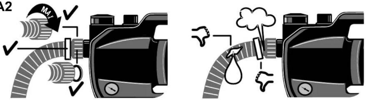
A5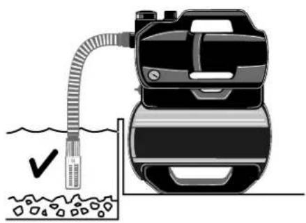
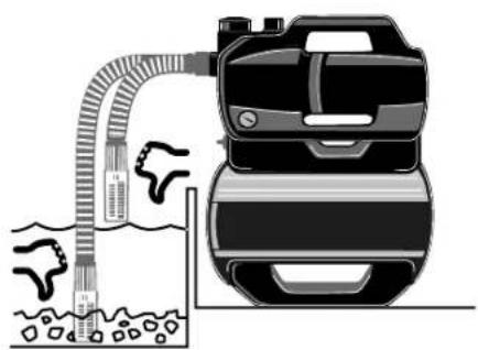
A7 | A8 | |
A9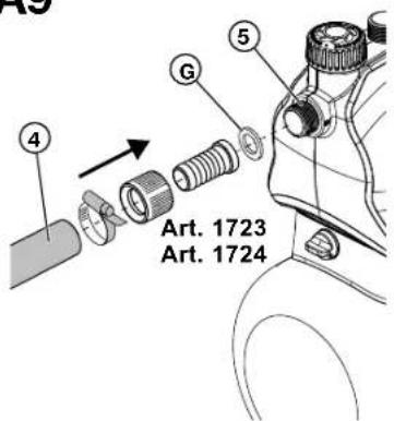 | A1001 |  |
C000 |  | N4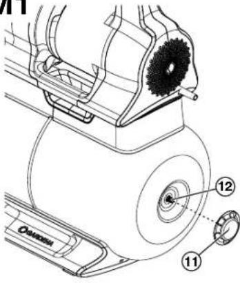 |
M001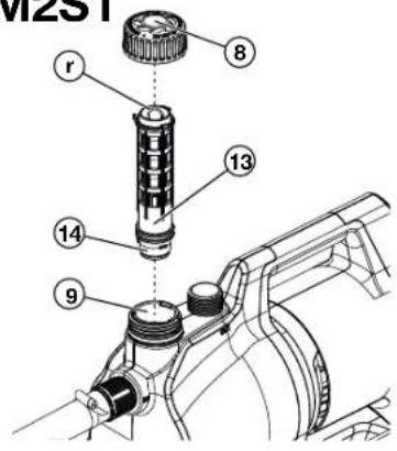 |  | T1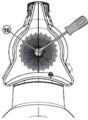 |
Domestic waterworks 3800 Silent / 3900 Silent
Translation of the original instructions.
- SAFETY WARNINGS....9
- FUNCTION 10
- INSTALLATION 10
- OPERATION 11
- MAINTENANCE....12
- STORAGE 12
- TROUBLESHOOTING 12
- TECHNICAL DATA 13
- ACCESSORIES/SPARE PARTS 13
- WARRANTY/SERVICE 14
- DISPOSAL 14
1. SAFETY WARNINGS
1.1 Explanation of the symbols:
→ Read the operator's manual.
1.2 General safety warnings
1.2.1. General pump safety instructions

DANGER!
Electric shock.
Risk of injury from electrical current.
→ The product must be supplied with power via a residual-current device (RCD) with a rated tripping current of no more than 30 mA. → Disconnect the product from the mains before decommissioning it, servicing it or replacing parts. When doing so, the power outlet must be within your field of vision.
1.3 Safety instructions for pumps
1.3.1. Safe operation
The water temperature must not exceed 35°C. The pump must not be used when there are people in the water.
1.3.2. Circuit breakers
Thermal circuit breakers: In the event of an overload, the pump is switched off by the integral thermal motor protection. After the motor has cooled down sufficiently, the pump is ready for operation again.
1.4 Additional safety warnings
1.4.1. Intended use
This product can be used by children aged from eight years and above and persons with reduced physical, sensory or mental capabilities or without experience and knowledge provided they are supervised or have been instructed on using the product safely and understand the hazards involved. Children must not play with the product. Cleaning and user maintenance must not be performed by children without supervision unless they are eight years of age or older and are supervised.
The use of this product by young people under the age of 16 is not recommended.
The GARDENA pressure tank unit is intended for pumping ground and rainwater, tap water and chlorinated water in private gardens and allotments.
The product is not intended for commercial use.
The product is not intended for permanent operation.
1.4.2. Transport fluids
The GARDENA pressure tank unit may only be used to transport water.

DANGER!
Risk of injury
Do not convey salt water, dirty water, corrosive, highly flammable or explosive substances (for example petrol, petroleum, nitro thinners), oils, fuel oil or food.
1.4.3. Additional electrical safety warnings:

DANGER!
Risk of cardiac arrest
This product generates an electromagnetic field while it operates. This electromagnetic field may affect the functionality of active or passive medical implants (e.g. pacemakers), which may result in serious injury or death.
→ Consult your doctor and the manufacturer of your implant before using this product.
→ After using the product, disconnect the mains plug from the mains socket.
→ Place the pump in a stable and flood-proof position so that it cannot fall into the water. → Set the pump at a safe distance (min. 2 m) from the transport fluid. An approved personal safety switch can be used as an additional safety feature for the residual-current device (RCD). → Ask a qualified electrician about this. The information on the rating plate must match the mains data. → Unplug the pump before anyone enters a swimming pool connected to it. If the mains connection cable of this machine is damaged, it must be replaced by the manufacturer or its after sales service team or a similarly qualified person to avoid danger. → Protect the mains plug and mains connection cable from heat, oil or sharp edges. → Do not carry the pump by the cable or use the cable to remove the plug from the wall socket. → Install the pressure tank unit in a flood-proof location. → Do not expose the pump to rain or use the pump in a wet or humid environment. → Check the connection cable at regular intervals. → Always conduct a visual inspection of the pump (especially the mains connection cable and mains plug) before use. A damaged pump must not be used. → It is essential to have the pump checked by GARDENA Service if it is damaged. Electrical modifications may only be carried out by a qualified electrician. → Disconnect the pump from the mains before filling, removal or maintenance. → Take heed of the generator manufacturer's warnings when using our pumps with a generator.
1.4.4. Cables
When using extension cables, they must comply with the minimum cross-sections in the following table:
| Voltage Cable length Cross-section | |
| 230-240 V/50 Hz Up to 20 m 1.5 mm 2 | |
| 230-240 V/50 Hz 20-50 m 2.5 mm 2 |
1.4.5. Additional personal safety warnings

DANGER!
Risk of suffocation
Small parts can easily be swallowed. There is a choking hazard for small children due to the polybag.
→ Keep small children away whilst you install the product.

DANGER!
Risk of injury from hot water
The pumped water is pressurised and can cause injury if it directly strikes the body or eyes.
→ Disconnect the pump from the mains and let the water cool down. → Do not open caps or fittings when the water is hot.
→ Before restarting, ensure the intake water supply is correct and fill the pump completely with water.
If hoses or pipes are exposed to the sun, they can become very hot.
→ Do not use the product with untied hair. → Do not connect the pump to the drinking water supply. → To prevent the pump from running dry, make sure that the suction hose end is always in the transport medium. → Fill the pump up to the overflow (min. 2.2 l) with water before starting it each time. → When filling the pump with water, make sure that no hoses or consumers are connected to the pump and that the pump is generally horizontal. → Make sure that the hoses are not kinked. Sand and other abrasive materials cause faster wear and reduced pump performance. → If water contains sand, use a pump pre-filter. Pumping contaminated water, for example containing stones, pine needles etc., can damage the pump. → Do not pump heavily contaminated water.
2. FUNCTION
2.1 How the pressure tank unit works
After being filled, the pump unit draws in water from a depth of up to 8 m and pumps it into the reservoir. This stores the water, which is pressurised by means of a pre-set air pressure and a separating membrane.
The pump unit starts when water is removed and the intended initial pressure is reached (see „8. Technical data“) and stops the filling process again when the cut-off pressure is reached. This means that small quantities of water can be pumped out of the tank in an energy-efficient manner. At high flow rates, such as for irrigation, however, the pressure fluctuations between the on and off pressure are clearly perceptible.
3. INSTALLATION

DANGER!
Risk of injury
Risk of injury due to unintentional startup.
→ Disconnect the power cable plug from the mains socket.
3.1 Installation location
- If installed below water level, a shut-off device must be installed to prevent unwanted water loss.
- The installation location must be horizontal, firm and dry and provide the pressure tank unit with firm support.
- It must be located at least 2 m away from open water.
- The pressure tank unit must be installed in a dry and flood-proof place with sufficient ventilation around the ventilation slots.
- It must be at least 5 cm away from walls.
- No dirt (for example sand or earth) may be sucked in through the ventilation grille.
3.1.1 Installing the pressure tank unit [Fig. A6/A7/A8]
- The pressure tank unit can be screwed to a firm surface. See Fig. A7 below for a sketch of the hole spacing. We suggest that four screws 7.5 x 45 (concrete screw) or 8 x 45 (wood screw) are used to install it on the floor.
- Ensure that the surface does not suffer from vibrations. Hex head screws are recommended.
- Set up the pressure tank unit so that you can place a receptacle of the appropriate size for emptying the pump under the drain screw (15). To prevent water leaking onto the floor during the emptying process and to allow the pump unit to be emptied fully, it must be possible to tilt the pressure tank unit forwards by approx. 80° towards the drain screw (15).
- Position the pressure tank unit so that the mains switch is easily accessible.
- If possible, install the pressure tank unit higher than the surface of the water you wish to pump. If this is not possible, install a vacuum-resistant shut-off valve between the pump unit and the suction hose.
- When permanently installing the pressure tank unit indoors for the domestic water supply, the pressure tank unit should not be firmly connected to rigid pipes but to the pipe network on the pressure side via flexible hose lines (e.g. armoured hose) in order to reduce noise and avoid damage to the pump unit due to water hammer.
- Use suitable shut-off valves for permanent installation on the pressure side. This is important for maintenance and cleaning work or for decommissioning, for example.
A 1:1 drill template [Fig. A6] is provided at the back of the operating manual (261 mm x 190 mm).
- Drill the hole pattern of the 1:1 drilling template [Fig. A6] on your selected (solid) surface (3).
- Use a screwdriver (max. 5 mm) and insert it into the side hole (h) of one cover ① [Fig. A7].
- Press the screwdriver to release the snap-on hook (2 hooks per cover ①).
- While holding down the snap-on hook, pull the side cover ① off the foot of the pressure vessel. Use the same procedure for the second cover.
- Screw the pressure tank unit to the solid surface (2) by hand using four hex head screws (3) (not supplied) [Fig. A8].
- Push the two side covers (1) back onto the foot of the pressure vessel until the snap-on hooks snap into place.
3.2 Connecting the hose to the suction side
The suction side connection (5) features with a 33.3 mm (G 1") external thread.
The connection piece on the suction side may only be tightened by hand [Fig. A2].
A suction hose with a backflow preventer must be used to prevent malfunctions and ensure a short time is required to resume priming. Drawing air into the suction system may result in a loss of function and increased noise.
→ Connect the suction system carefully.
→ Check the seal at regular intervals and replace it if necessary.
Do not use modular water hose components on the suction side.
A vacuum-resistant suction hose must be used on the suction side [Fig. A3]:
For example, the GARDENA suction set Art. 1411/1412/1418
• or the GARDENA fountain suction hose Art. 1729. - Connect suction hoses (4) without a threaded connection to the connection on the suction side using a suction connection set (for example Art. 1723/1724) (4), ensuring it is airtight.
Note: Leaks on the suction side cannot be seen [Fig. A9].
3.2.1 There are two types of connection systems
Designed for a flat gasket:
Among other things, all GARDENA connectors are made of plastic. No thread sealing tape is required.
→ Ensure that the flat gasket (G) is inserted into the suction hose fitting and is undamaged.
Designed for thread sealing tape (hemp/Teflon):
If you use different connections, use sealing tape on the male thread of the connections.
An incorrect sealing system may cause leaks/air ingress and reduce the suction capacity.
→ Use the sealing system provided for this purpose.
3.2.2 Connecting the suction hose [Fig. A9]
- Ensure that the flat gasket (G) is inserted into the suction hose fitting.
- Screw the vacuum-resistant suction hose (4) onto the connection on the suction side (5) so that it is airtight. The suction hose fitting must be installed straight [Fig. A1].
- Route the suction hose (4) so that it is straight and not twisted.
- For suction heights above 3 m: Also secure the suction hose (4) (for example, tie it to a wooden peg).
This takes the weight of the suction hose off the pump.
If the water has very fine contamination, in addition to the integrated filter, a
Gardena pump pre-filter Art. 1730/1731 is recommended.
3.3 Connecting the hose to the pressure side
To ensure good venting, do not connect the pressure hose until the pump has been filled (see „4.1.1 Starting the pump“).
There are two connectors on the pressure side. These feature a 33.3 mm (G 1") external thread.
The connection piece on the pressure side may only be tightened by hand.
A fixed pipe must be installed at an upward angle so that water can flow back into the pump on the pressure side.
The pump's delivery rate can be used efficiently by connecting 19 mm (3/4") hoses in combination with the following:
- the GARDENA pump connection set Art. 1752, for example,
- or 25 mm (1") hoses with the GARDENA female quick thread coupling Art. 7109/Quick coupling hose connector Art. 7103.
There are two connections on the pressure side. One horizontal (180° rotatable) and one vertical connection. The unused connection must be closed with the plug cap (7a).
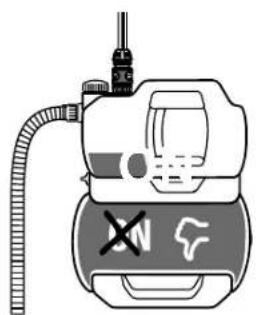
Hold or fix the pressure hose vertically to prevent it kinking at the vertical pump outlet.
Lay the hose flat on the ground and ensure that there are no U-shaped rises in it or coiled hoses. The best way of allowing air to escape is for the pressure hose to be stretched out so that it runs upwards when viewed from the pump.
3.3.1 Connecting the pressure hose [Fig. A10]
→ Connect the pressure hose to the connection on the pressure side (7).
→ Ensure that the flat gasket (G) is inserted into the connection.
If you use different connections, use sealing tape on the male thread of the connections.
3.3.2 Connecting the pressure hose using the GARDENA combi system
A GARDENA pump connection Art. 1745, for example, is required for the GARDENA combi system.
The GARDENA combi system can be used to connect 19 mm (3/4")/16 mm (5/8") and 13 mm (1/2") hoses.
Hose diameter Pump connection
| 13 mm ( 1/2 ") GARDENA pump connection set Art. 1750 | |
| 16 mm ( 5/8 ") GARDENA tap connector | Art. 18202 |
| GARDENA hose connector | Art. 18216 |
19 mm (3/4") GARDENA pump connection set Art. 1752
4. OPERATION

Risk of injury due to unintentional startup. → Disconnect the plug from the mains socket.
4.1 Starting/stopping the pump [Fig. 01/02/03]
![GARDENA 3900 Silent - Starting/stopping the pump [Fig. 01/02/03] - 1](/content/2026/07/1455082/images/a57a3732a4625a46db8aa3124ca1db8c918b49013b70a27e1b30282ba93aebab.jpg)
→ Make sure that the pump is filled with water up to the overflow before you start it (at least 1.2 l).
4.1.1 Starting the pump
- Connect the suction hose (In).
- Remove the pressure hose (Out).
- Screw the cover ⑧ onto the filling opening ⑨ by hand.
- Pull out the filter (Fig. M2) and slowly add approximately 1.5 l of water through the filling opening ⑨ until a stable water level is reached that is level with the suction connection (Fig. A4). Then reinsert the filter.
- If using a suction set with check valve: Fill the suction hose with water. This speeds up the priming process.
- Drain the residual water out of the pressure hose ⑥ before connecting it. This allows the air to escape during the priming process.
- After filling the pump: Connect the pressure hose (Out) to the pump.
- Screw the cover ⑧ onto the filling opening ⑨ by hand (do not use any tools).
- Open any shut-off valves in the delivery line (watering accessories, water stop etc.). All consumers must be open as wide as possible.
- Connect the power cable plug to a mains socket.
- For high suction heights: Lift and hold the pressure hose⑥ at least 1.8 m above the pump during the priming process.
- Move the On/Off switch⑩ to the On position.
The pump starts (the On/Off switch lights up) and pumps the water after the priming process.
The pressure gauge ⑰ shows the water pressure in the reservoir.
The priming process can take up to five minutes.
Note: When using for the first time, there may be a brief (approx. 10 seconds) increase in noise level near the tank.
4.1.2 If the pump is not pumping water after five minutes
- Move the On/Off switch ⑩ to the Off position.
The pump stops.
- Let the pump cool down.
- Look for possible causes in „7.2 Error table“.
- Restart the pump (see „4.1.1 Starting the pump“).
4.1.3 Stopping the pump
Move the On/Off switch to the Off position.
The pump stops.
4.2 Pump tips
4.2.1 Quiet operation:
The pressure tank unit is quiet. This positive feature can only be maintained if it is installed correctly:
Select a low-vibration surface (do not place it on metal sheets or plastic tanks, for example).
4.2.2 Installing a pre-filter (accessory)
If a pre-filter is too long, it may be installed in a different position (for example horizontally) rather than vertically facing downwards.
4.2.3 Using sprinklers
Switching the pump unit on and off automatically may result in an uneven irrigation pattern depending on the flow rate of the sprinkler.
5. MAINTENANCE

DANGER!
Risk of injury
Risk of injury due to unintentional startup.
→ Disconnect the power cable plug from the mains socket.
→ Make sure that all parts have been properly secured after maintenance.
5.1 Cleaning the pressure tank unit [Fig. M1]
![GARDENA 3900 Silent - Cleaning the pressure tank unit [Fig. M1] - 1](/content/2026/07/1455082/images/9fd2508625b793b8f02a88e7e49b878d58e270f07154042b413a2373b1df3040.jpg)
DANGER!
Risk of injury and damage to property!
Not cleaning the product properly can injure people and damage the product.
→ Do not use water or a water jet (especially a high-pressure water jet) to clean the product.
→ Do not use chemicals, including gasoline or solvents, to clean the product.
Some of these substances can destroy important plastic parts.
The ventilation slots must always be kept clean.
- Clean the housing of the pressure tank unit with a damp cloth.
- Clean the ventilation slots with a soft brush (do not use sharp objects).
5.2 Flushing the pump
The pump must be flushed after it has pumped chlorinated water.
- Pump lukewarm water (max. 35°C), possibly with the addition of a mild cleaning fluid (e.g. washing-up liquid), until the pumped water is clear.
- Dispose of the residues as specified in local waste disposal guidelines.
5.3 Checking the air pressure in the reservoir [Fig. M1]
→ Check the air pressure in the reservoir if the device starts to misbehave. The air pressure in the reservoir must be approx. 1.0 bar. An air pump/tyre inflater with a pressure gauge is required to top up the air. Excessive air pressure does not increase the water pressure and causes malfunctions.
- Unscrew the protective cover (11).
- Open any shut-off valves in the delivery line (watering accessories, water stop etc.).
This causes the pressure side to depressurise.
- Attach the air pump/tyre inflater to the reservoir valve (car valve) (12).
- Top up with air until the pressure gauge on the air pump/tyre inflater shows approx. 1.0 bar.
- Screw the protective cover (11) back into place.
5.4 Cleaning the integrated filter and check valve [Fig. M2]
Depending on the level of water pollution, the filter should be cleaned at regular intervals, at the latest if it malfunctions.
- Close all the shut-off valves on the suction side.
- Open any shut-off valves in the delivery line (watering accessories, water stop etc.).
This causes the pressure side to depressurise.
- Unscrew the fitting ⑧ on the filler neck ⑨ by hand (do not use tools).
- Pull the filter (13) out of the filler neck ⑨ using the removal tool (r).
- Clean the filter (13) and check valve (14) under running water and, if necessary, a soft brush or mild cleaning fluid.
- Lubricate the outer O-ring on the filter (13) with environmentally friendly machine grease.
This will make it easier to remove the filter the next time it needs cleaning.
- Install the filter (13) and check valve (14) in reverse order.
6. STORAGE

CAUTION!
Pump frost damage
Risk of injury due to unintentional startup.
→ Store the pressure tank unit in a frost-proof place.
6.1 Decommissioning [Fig. S1]
The product must be stored away from children.
- Disconnect the plug from the mains socket.
- Close any shut-off valves in the suction line.
- Open any shut-off valves in the delivery line (watering accessories, water stop etc.).
This causes the pressure side to depressurise.
- Screw on the fitting ⑧ on the filler neck ⑨ and the water drain plug (15) by hand.
This will drain the pump.
- Tilt the pressure tank unit slightly towards the drain (up to 80") so that the pump drains fully.
- Unscrew the suction hose and the pressure hose.
- Tighten the fitting ⑧ on the filling opening ⑨ and the water drain plug (15) by hand (do not use any tools).
- Store the pressure tank unit in a dry, covered and frost-proof location.
7. TROUBLESHOOTING

DANGER!
Risk of injury
Risk of injury due to unintentional startup.
→ Disconnect the plug from the mains socket,
→ Allow the pump to cool before troubleshooting.
7.1 Undo the impeller [Fig. T1]
If the impeller has been blocked by contamination, it can be released.
→ Turn the impeller shaft (15) clockwise using an insulated screwdriver. This will release the blocked impeller.
7.2 Error table
Problem Possible cause Remedy
| Pump runs but does not create suction | Leaking or damaged suction line [Fig. A2]. | → Check the suction line for damage and seal it so that it is airtight. |
| A totally vacuum-tight connection can be achieved by using GARDENA suction hoses (see „9. Accessories/spare parts“). | ||
| Pump draws in air at a connection point [Fig. A2]. | → Seal the connections on the suction side so that they are airtight. | |
| There is no water in the cistern, water tank, water pipe etc. | → Ensure that there is a water supply on the suction side. | |
| Pump was not filled with water [Fig. A4]. | → Fill the pump (see „4.1.1 Starting the pump“). | |
| Water escapes through the pressure hose during the priming process. | 1. Refill the pump.2. Hold up the pressure hose.3. Restart the pump. (see „4.1.1 Starting the pump“). | |
| There is a leak in the fitting on the filler neck [Fig. A2]. | → Check the seal (replace if necessary) and tighten the fitting by hand (do not use tools). | |
| Air cannot escape because the delivery line is sealed or there is residual water in the pressure hose. | → Open the shut-off valves (for example nozzle) in the delivery line or empty the pressure hose. | |
| Air cannot escape because the pressure hose is wound up | 1. Lay the pressure hose out straight to its full length.2. Route the hose up from the pump outlet.3. Do not bend the pressure hose at the pump outlet.4. Open all consumers to the maximum setting. | |
| The priming process has not yet been completed. | → Wait for up to five minutes until the pump pumps water. | |
| Suction filter or backflow preventer in the suction hose are clogged. | → Clean the suction filter or backflow preventer. | |
| The end of the suction hose is not in water [Fig. A5]. | → Immersion the suction hose end deeper into the water. | |
| The suction height is too great [Fig. A5]. | → Reduce the suction height. | |
| In the case of other suction problems, use GARDENA suction hoses with backflow preventer (see „9. Accessories/spare parts“).Fill the pump with water before starting. | ||
| Pump does not start or stops suddenly during operation | Thermal overload switch has shut down the pump due to overheating. | → Let the pump cool down, drain the pump and refill it.→ Note the maximum media temperature (35°C). |
| Pump has no power. | → Check the fuses and electrical connectors. | |
| RCD switch has tripped (residual current). | → Remove the plug from the mains socket and contact GARDENA Service. | |
| Pump Is running, but the flow rate decreases suddenly | The integral filter is clogged | → Clean the integral filter |
| The end of the suction hose is not in water [Fig. A5]. | → Immersion the suction hose end deeper into the water. | |
| Suction filter or backflow preventer in the suction hose are clogged. | → Clean the suction filter or backflow preventer. | |
| There is no water in the cistern, water tank, water pipe etc. | → Ensure that there is a water supply on the suction side. | |
| Suction line is leaking [Fig. A2]. | → Rectify the leak. | |
Problem Possible cause Remedy
| Impeller is blocked. → Release the impeller. | ||
| Pressure hose is kinked. | → Route the pressure hose without kinking it and do not bend the pressure hose at the pump outlet. | |
| The filter cannot be unscrewed by hand | The thread is dirty. | → To unscrew the component, use multigrip pliers with a cloth between the component and the pliers.→ Clean the thread on the filter and in the pump. |
| Unusual switching behaviour (suddenly different). | The pressure in the reservoir is too low. | → Refill the air in the reservoir to 1 bar pressure. |
| Leakage on the pressure side. | → Eliminate the leak on the pressure side. | |
| The reservoir membrane is damaged. | → Have the product checked by GARDENA Service. | |
IMPORTANT!
Repairs may only be carried out by GARDENA service centres or by specialist dealers approved by GARDENA.
→ Please contact your GARDENA service centre in the event of other faults (see overleaf).
8. TECHNICAL DATA
| Pressure tank unit Unit Value | (Art. 9064) | Value(Art. 9066) | |
| Rated power W 600 | 650 | ||
| Mains voltage | V (AC) | 230 | 230 |
| Mains frequency | Hz | 50 | 50 |
| Max. delivery capacity | l/h | 3800 | 3900 |
| Max. pressure/Max. delivery head | bar/m | 3.939 | 4.343 |
| Max. self-priming level | m | 8 | 8 |
| Operating pressure p(W)Cut-in pressureCut-out pressure | bar | 1.5 ±0.12.7 +0.1 | 1.5 ±0.13.0 +0.1 |
| Permitted Internal pressure (delivery side) | bar | 6 | 6 |
| Air pressure in tank | bar | 1.0 | 1.0 |
| Power cable | m | 1.5 (H07RN-F) | 1.5 (H07RN-F) |
| Weight without cable (approx.) | kg | 12.7 | 13.4 |
| Sound pressure level LPA Distance: 1 m | dB | 61 | 62 |
| 5 m | dB | 47 | 48 |
| 10 m | dB | 41 | 42 |
| Sound power noise level LWA1) measured/guaranteed | dB(A) | 70 / 72 | 70 / 72 |
| Uncertainty kWA | dB(A) | 2.39 | 2.42 |
| Max. media temperature | °C | 35 | 35 |
Measurement methods according to: 1) Directive 2000/14/EU
9. ACCESSORIES/SPARE PARTS
| GARDENA suction hoses | Kink- and vacuum-resistant, available either by the metre Art. 1720/1721 (19 mm (3/41)/25 mm (1") without connection fittings or in fixed lengths Art. 1411/1418 complete with connection fittings. | |
| GARDENA suction hose connector | For connection on the suction side. | Art. 1723/1724 |
| GARDENA pump connection set For connection on the pressure side. Art. | 1750/1752 | |
| GARDENA suction filter with backflow preventer | For installing in suction hoses supplied by the metre. | Art. 1726/1727/1728 |
| GARDENA pump pre-filter Recommended for pumping water that contains sand. | Art. 1730/1731 | |
| GARDENA fountain suction hose | For vacuum-resistant connection of the pump to a fountain or rigid pipes, Length 0.5 m. With 33.3 mm (G 1) female thread on both sides. | Art. 1729 |
| GARDENA floating suction | For dirt-free suction below the water surface. | Art. 1417 |
| GARDENA quick coupler | For pressure side connection of 1" pressure hoses. | Art. 7109/7103 |
10. WARRANTY/SERVICE
10.1 Product registration
Please register your product at gardena.com/registration.
10.2 Service
Please find the current contact information of our service on the back page and online:
• United Kingdom: https://www.gardena.com/uk/support/advice/contact/ • Australia: https://www.gardena.com/au/support/advice/contact/ • New Zealand: https://www.gardena.com/nz/support/advice/contact/ • South Africa: https://www.gardena.com/za/support/contact/
11. DISPOSAL
11.1. Disposing of the pressure tank unit
(In compliance with Directive 2012/19/EU/S.I. 2013 No. 3113):

The product must not be disposed of together with normal household waste. It must be disposed of in line with local environmental regulations.
IMPORTANT!
→ Dispose of the product through or via your local recycling collection centre.
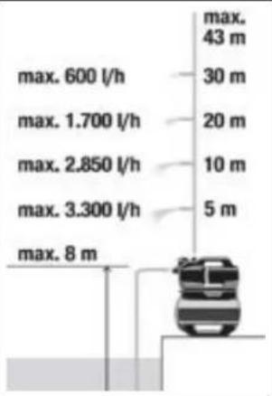
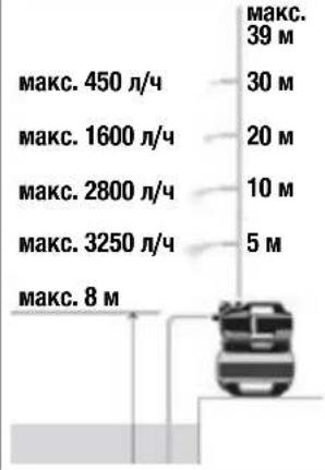
Performance characteristics
| 3800 Silent Art. 9064 | |
| max. 450 l/h | max. max. 39 m |
| max. 450 l/h | 30 m |
| max. 1600 l/h | 20 m |
| max. 2800 l/h | 10 m |
| max. 3250 l/h | 5 m |
| max. 8 m |  |
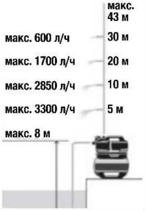
| 3800 Silent, Ref. 9064 3900 Silent, Ref. | 9066 |
 |  |
and 3800 Silent / 3900 Silent submersible pump
DANGER! Risk of injury
10. WARRANTY/SERVICE
10.1 Product registration
Register the product at gardena.com/registration.
10.2 Service
- https://www.gardena.com/lv/service-and-support/find-a-dealer-or-service-center/
11. DISPOSAL
11.1. Disposal of the pressure tank unit (in accordance with Directive 2012/19/EU/S.I. 2013 No. 3113):

- SAFETY WARNINGS 81
- OPERATION 82
- INSTALLATION 82
- OPERATION 83
- MAINTENANCE 84
- STORAGE 84
- TROUBLESHOOTING 84
- TECHNICAL DATA....85
- ACCESSORIES/SPARE PARTS 85
- WARRANTY/SERVICE 86
- DISPOSAL 86
1. SAFETY WARNINGS
7. TROUBLESHOOTING

DANGER!
Risk of injury
Register your product at gardena.com/registration.
10.2 Service
Hose diameter Pump connection
| 13 mm ( 1/2 ") GARDENA-pumpekoblingssett Art. 1750 | |
| 16 mm ( 5/8 ") GARDENA-krankobling | Art. 18202 |
| GARDENA-slangekobling | Art. 18216 |
19 mm (3/4") GARDENA pump connection set Art. 1752
4. USE

Liability for personal injury
- Other countries: https://www.gardena.com/int/support/advice/contact/
11. DISPOSAL
• Romania: https://www.gardena.com/ro/asistenta/advice/contact/ - Other countries: https://www.gardena.com/int/support/advice/contact/
11. DISPOSAL
- https://www.gardena.com/int/support/advice/contact/
11. DISPOSAL
| 3800 Silent, apt. 9064 3900 Silent, apt. | 9066 |
 |  |
1720/1721 (19 mm (3/4")/25 mm
- https://www.gardena.com/int/support/advice/contact/
11. DISPOSAL
- https://www.gardena.com/int/support/advice/contact/
11. DISPOSAL
9064-20.965.02/0124 9064-61.965.02/0124 © GARDENA Manufacturing GmbH D 80079 Ulm https://www.gardena.com


- DOMESTIC WATERWORKS 3800 SILENT / 3900 SILENT
- TRANSLATION OF THE ORIGINAL INSTRUCTIONS
- SAFETY WARNINGS
- EXPLANATION OF THE SYMBOLS
- GENERAL SAFETY WARNINGS
- GENERAL PUMP SAFETY INSTRUCTIONS
- DANGER
- ELECTRIC SHOCK
- SAFETY INSTRUCTIONS FOR PUMPS
- SAFE OPERATION
- CIRCUIT BREAKERS
- ADDITIONAL SAFETY WARNINGS
- INTENDED USE
- TRANSPORT FLUIDS
- RISK OF INJURY
- ADDITIONAL ELECTRICAL SAFETY WARNINGS
- RISK OF CARDIAC ARREST
- CABLES
- ADDITIONAL PERSONAL SAFETY WARNINGS
- RISK OF SUFFOCATION
- RISK OF INJURY FROM HOT WATER
- FUNCTION
- HOW THE PRESSURE TANK UNIT WORKS
- INSTALLATION
- INSTALLATION LOCATION
- INSTALLING THE PRESSURE TANK UNIT [FIG. A6/A7/A8]
- CONNECTING THE HOSE TO THE SUCTION SIDE
- A VACUUM-RESISTANT SUCTION HOSE MUST BE USED ON THE SUCTION SIDE [FIG. A3]
- THERE ARE TWO TYPES OF CONNECTION SYSTEMS
- DESIGNED FOR A FLAT GASKET
- DESIGNED FOR THREAD SEALING TAPE (HEMP/TEFLON)
- CONNECTING THE SUCTION HOSE [FIG. A9]
- CONNECTING THE HOSE TO THE PRESSURE SIDE
- THE CONNECTION PIECE ON THE PRESSURE SIDE MAY ONLY BE TIGHTENED BY HAND
- THE PUMP'S DELIVERY RATE CAN BE USED EFFICIENTLY BY CONNECTING 19 MM (3/4") HOSES IN COMBINATION WITH THE FOLLOWING
- CONNECTING THE PRESSURE HOSE [FIG. A10]
- CONNECTING THE PRESSURE HOSE USING THE GARDENA COMBI SYSTEM
- OPERATION
- STARTING/STOPPING THE PUMP [FIG. 01/02/03]
- STARTING THE PUMP
- IF THE PUMP IS NOT PUMPING WATER AFTER FIVE MINUTES
- STOPPING THE PUMP
- PUMP TIPS
- QUIET OPERATION
- INSTALLING A PRE-FILTER (ACCESSORY)
- USING SPRINKLERS
- MAINTENANCE
- CLEANING THE PRESSURE TANK UNIT [FIG. M1]
- RISK OF INJURY AND DAMAGE TO PROPERTY
- THE VENTILATION SLOTS MUST ALWAYS BE KEPT CLEAN
- FLUSHING THE PUMP
- CHECKING THE AIR PRESSURE IN THE RESERVOIR [FIG. M1]
- CLEANING THE INTEGRATED FILTER AND CHECK VALVE [FIG. M2]
- STORAGE
- CAUTION
- PUMP FROST DAMAGE
- DECOMMISSIONING [FIG. S1]
- THE PRODUCT MUST BE STORED AWAY FROM CHILDREN
- TROUBLESHOOTING
- UNDO THE IMPELLER [FIG. T1]
- ERROR TABLE
- IMPORTANT
- TECHNICAL DATA
- ACCESSORIES/SPARE PARTS
- WARRANTY/SERVICE
- PRODUCT REGISTRATION
- SERVICE
- DISPOSAL
- DISPOSING OF THE PRESSURE TANK UNIT
- AND 3800 SILENT / 3900 SILENT SUBMERSIBLE PUMP
- DANGER! RISK OF INJURY
- DISPOSAL OF THE PRESSURE TANK UNIT (IN ACCORDANCE WITH DIRECTIVE 2012/19/EU/S.I. 2013 NO. 3113)
- USE
- LIABILITY FOR PERSONAL INJURY
Brand : GARDENA
Model : 3900 Silent
Category : Water pump