
5600 SilentComfort - Water pump GARDENA - Free user manual and instructions
Find the device manual for free 5600 SilentComfort GARDENA in PDF.


| Product Type | Water Pump |
| Brand | Gardena |
| Model | 5600 SilentComfort |
| Dimensions (L x W x H) | 400 x 250 x 300 mm |
| Weight | 10.5 kg |
| Power Supply | 230 V / 50 Hz |
| Power Consumption | 600 W |
| Max. Flow Rate | 5600 L/h |
| Max. Delivery Head | 45 m |
| Max. Pressure | 4.5 bar |
| Noise Level | 45 dB(A) (SilentComfort) |
| Protection Class | IPX4 |
| Housing Material | Stainless Steel / Plastic |
| Suction Connection | 1" (25 mm) |
| Delivery Connection | 1" (25 mm) |
| Max. Liquid Temperature | 35 °C |
| Functions | Automatic pressure switch, dry-run protection, thermal protection |
| Maintenance | Regular cleaning of filter; check for leaks |
| Safety Features | Thermal cut-out, automatic shut-off |
| Spare Parts Availability | Yes (service kit available) |
| Repairability Index | 8.5/10 |
| General Information | Suitable for garden irrigation and water supply from tanks or wells |
Frequently Asked Questions - 5600 SilentComfort GARDENA
User questions about 5600 SilentComfort GARDENA
0 question about this device. Answer the ones you know or ask your own.
Ask a new question about this device
Download the instructions for your Water pump in PDF format for free! Find your manual 5600 SilentComfort - GARDENA and take your electronic device back in hand. On this page are published all the documents necessary for the use of your device. 5600 SilentComfort by GARDENA.
USER MANUAL 5600 SilentComfort GARDENA
5600 SilentComfort Art. 9067
6300 SilentComfort Art. 9068
en Operator's manual
Pressure Tank Unit
A1

A2

A3

A4

A5

A7 | A8 | A9 |
A10 | A11 | C1 |
O2 | M1 | M2 |
T1 | ||
M3 | M4 | S1 |
Translation of the original instructions.
1 Terms and abbreviations....6
2 Safety instructions ....7
2.1 Symbols on the product 7 2.2 General safety instructions....7 2.3 Additional safety instructions 8
3 Assembly....10
3.1 Selecting the installation location 10 3.2 Screwing the PTU onto a surface [Fig. A6/A7/A8].... 10 3.3 Connecting the suction side 10
3.3.1 Types of connection systems 11 3.3.2 Connecting the suction hose [Fig. A9] 11
3.4 Connecting the hose to the pressure side....11
3.4.1 Connecting the pressure hose [Fig. A10].... 12 3.4.2 Connect the pressure hose via the GARDENA combi system....12 3.4.3 Parallel connection of pressure hoses....12
3.5 Connecting the soil moisture sensor (optional) [Fig. A11].... 12
4 Commissioning....13
4.1 Initial commissioning 13
4.1.1 Commissioning the PTU for the first time.... 13 4.1.2 Selecting a language.... 13
4.2 Starting/stopping the pump unit [Fig. O1/O2] 13
4.2.1 Starting the pump unit.... 13 4.2.2 Stopping the pump unit.... 14 4.2.3 Max. flow values....14
4.3 Installing a pre-filter (accessory)....14 4.4 Using sprinklers.... 14
5 Functions....15
5.1 How the pressure tank unit works 15 5.2 Adjustable pressure ranges 15 5.3 Power Boost 15 5.4 Bluetooth® 15 5.5 Timers and watering schedules 15
5.5.1 Timer 16 5.5.2 Irrigation schedules (exclusive app function) 16 5.5.3 Optional soil moisture sensor (Art. 1867) 16
5.6 Safe-pump 16
5.6.1 Automatic restart.... 16
5.7 Reminder 16 5.8 Direct start 16 5.9 Safety 17
5.9.1 Leakage detection 17 5.9.2 Maximum run time 17 5.10 Factory settings 17
6 Operation 18
6.1 Operating the pressure tank unit via app 18 6.2 Operating the pressure tank unit with the keys 18
6.2.1 Symbols on the screen 18 6.2.2 Explanation of the control panel 18 6.2.3 Menu navigation 18 6.2.4 Power saving function 19 6.2.5 Child lock 19
7 Messages on the screen 20
7.1 Status indicators 20 7.2 Informative messages 20 7.3 On-screen messages related to Bluetooth® function 21
8 Settings 22
8.1 Timer 22 8.2 Mode (adjustable pressure ranges) 22
8.2.1 Mode selection 22 8.2.2 Individual mode 23
8.3 Power Boost 23 8.4 Bluetooth 24
8.4.1 Switching Bluetooth on and off 24 8.4.2 Pairing (connecting a mobile device for the first time) 24 8.4.3 Deleting devices 24
8.5 Brightness 25
8.6 Language 25 8.7 Reminder 26 8.8 Direct start 26 8.9 Safety 26
8.9.1 Leakage 27 8.9.2 Max. run time 27
8.10 Factory settings....27
9 Maintenance ....28
9.1 Cleaning the pressure tank unit [Fig. M1] 28 9.2 Flushing the pump unit 28 9.3 Checking the air pressure in the reservoir [Fig. M1] 28 9.4 Cleaning the filter [Fig. M2] 29 9.5 Cleaning the check valve [Fig. M3/M4]....29
10 Storage....30
10.1 Decommissioning and storage [Fig. S1]....30
11 Troubleshooting....31
11.1 Releasing the impeller [Fig. M3/T1]....31 11.2 Error messages....31
11.2.1 Messages related to errors 1, 2, 10 and 11....32 11.2.2 Errors 1 and 2....32 11.2.3 Error 10 and 11....33
11.3 Error table for the PTU....34
12 Technical data....36
13 Accessories/spare parts....37
14 Warranty/Service 38
14.1 Product registration....38 14.2 Service 38
15 Disposal 39
15.1 Disposal of the pressure tank unit 39
16 Annex 40
16.1 Assignment of trademarks....40 16.2 EC Declaration of Conformity 40
17 Performance characteristics ....41
1 TERMS AND ABBREVIATIONS
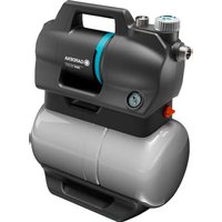
- PTU: This abbreviation stands for pressure tank unit. This is the name for the entire device incl. pump unit and pressure tank.
- Pump unit: Component mounted on the pressure tank that connects to the hose lines and pumps the water.
- Automatic mode: Automatic switching on and off of the pump unit due to water being drawn and the associated drop in pressure in the pressure tank.
- Pressure tank: The pressure tank is mounted under the pump unit and can store water under pressure and release it when removed. →Sentences preceded by an arrow are operating instructions.
2.1 Symbols on the product

→Read the operator's manual.
2.2 General safety instructions

DANGER! Electric shock
Risk of injury from electrical current.
→ The product must be supplied with power via a residual-current device (RCD) with a rated tripping current of no more than 30 mA. → Disconnect the product from the mains before decommissioning it, servicing it or replacing parts. When doing so, the power outlet must be within your field of vision.
2.2.1. Intended use
This product can be used by children aged eight years and above and persons with reduced physical, sensory or mental capabilities or without experience and knowledge, provided they are supervised or have been instructed on using the product safely and understand the hazards involved. Children must not play with the product. Cleaning and user maintenance must not be performed by children without supervision unless they are eight years of age or older and are supervised.
The use of this product by young people under the age of 16 is not recommended.
The GARDENA PTU is intended for pumping ground and rainwater, tap water, and chlorinated water in private gardens and allotments. The GARDENA PTUs 5600/6300 Bluetooth® Art. 9067/9068 are part of an irrigation system along with the Bluetooth® app.
The user interface is intended for manual operation via display and control keys, as well as via Bluetooth® with a mobile device.
The product is not intended for commercial use. The product is not intended for permanent operation.
2.2.2. Safe operation
The water temperature must not exceed 35°C. The PTU must not be used when there are people in the water.
2.2.3. Transport fluids
The GARDENA PTU may only be used to pump water.

DANGER! Risk of injury
→ Do not pump salt water, dirty water, corrosive, highly flammable or explosive substances (for example petrol, paraffin, nitro-cellulose thinners), oils, fuel oil or foodstuffs.
2.2.4. Extension cable
When using extension cables, they must comply with the minimum cross-sections in the following table:
Voltage Cable length Cross-section
| 230–240 V/50 Hz | Up to 20 m 1.5 mm 2 |
| 230–240 V/50 Hz | 20–50 m 2.5 mm 2 |

DANGER!
Risk of cardiac arrest
This product generates an electromagnetic field during operation. This electromagnetic field may affect the functionality of active or passive medical implants (e.g., pacemakers), which may result in serious injury or death.
→ Consult your doctor and the manufacturer of your implant before using this product. → After using the product, disconnect the mains plug from the mains socket.
2.3.1. Additional electrical safety instructions
→ Set up the PTU so that it is stable and cannot be submerged.
→ Set up the PTU so that it is protected against falling into the water.
Set up the PTU at a safe distance (min. 2 m) from the medium to be pumped.
→ An approved personal safety switch can be used as an additional safety feature for the residual-current device (RCD).
→ Ask a qualified electrician about this. → The information on the rating plate must match the mains data.
→ Unplug the PTU before anyone enters a swimming pool connected to it.
If the mains connection cable of this machine is damaged, it must be replaced by the manufacturer or its after-sales service team or a similarly qualified person to avoid danger.
→ Protect the mains plug and mains connection cable from heat, oil, and sharp edges. → Do not carry the PTU by the cable or use the cable to remove the plug from the wall socket. → Do not expose the PTU to rain or use the PTU in a wet or humid environment.
→ Check the connection cable at regular intervals.
→ Always conduct a visual inspection of the PTU (especially the mains connection cable and mains plug) before use.
A damaged PTU must not be used.
It is essential to have the PTU checked by GARDENA Service if it is damaged.
Electrical modifications may only be carried out by a qualified electrician.
Disconnect the PTU from the mains before filling, removal, or maintenance. Take heed of the generator manufacturer's warnings when using our PTU with a generator.
2.3.2. Additional personal safety instructions

DANGER!
Risk of suffocation
Small parts can easily be swallowed. Keep small children away when you assemble the product.

DANGER!
Risk of injury from hot water
The pumped water is pressurised and can cause injury if it directly strikes the body or eyes. If there is no water supply on the suction side, the water in the PTU may heat up and the hot water produced could cause injury if leakage occurs.
Disconnect the PTU from the mains and let the water cool down. Do not open caps or fittings when the water is hot.
Ensure that the water supply on the suction side is present before restarting.
If hoses or pipes are exposed to the sun, they can become very hot. Do not use the product with untied hair. Do not connect the PTU to the drinking water supply.
To prevent the pump unit from running dry, make sure that the suction hose end is always in the pumped medium.
Slowly fill the PTU up to the overflow (min. 2.2 l) with water before starting it each time.
When filling the PTU with water, make sure that no hoses or consumers are connected to the PTU and that the PTU is level.
Make sure that the hoses are not kinked.
Sand and other abrasive substances cause faster wear and reduced pump unit performance. If water contains sand, use a pump pre-filter.
Pumping contaminated water, for example containing stones, pine needles, etc., can damage the pump unit.
Do not pump heavily contaminated water.

DANGER!
Risk of injury
Risk of injury due to unintentional startup.
Disconnect the plug from the mains socket.
3.1 Selecting the installation location
- The surface must be low-vibration (e.g., do not place on metal sheets or plastic tanks) to ensure quiet operation.
- If installed below water level, a shut-off device must be installed to prevent unwanted water loss.
- The installation location must be level, firm, and provide the PTU with a secure footing.
- It must be located at least 2 m away from open water.
- The PTU must be installed in a dry location with sufficient ventilation and with no risk of submersion.
- It must be at least 5 cm away from walls.
- Set up the PTU so that you can place an appropriately sized receptacle for emptying the PTU under the drain screw ⑳.
- To prevent water leaking onto the floor during the emptying process and to allow the PTU unit to be emptied fully, it must be possible to tilt the PTU forwards by approx. 80° towards the drain screw ⑳.
- If possible, install the PTU higher than the surface of the water you wish to pump.
- If this is not possible, install a vacuum-resistant shut-off valve between the pump unit and the suction hose.
3.2 Screwing the PTU onto a surface [Fig. A6/A7/A8]
The PTU can optionally be screwed in place. A 1:1 drill template [Fig. A6] is provided at the back of the operating manual (261 mm x 190 mm). We recommend using four screws 7.5 x 45 (concrete screw) or 8 x 45 (wood screw) for installation on the floor. Hex head screws are recommended.
- Drill the hole pattern of the 1:1 drilling template [Fig. A6] on your selected (solid) surface ③.
- Use a screwdriver (max. 5 mm) and insert it into the side hole ① of one cover ① [Fig. A7].
- Press the screwdriver to release the snap-on hook (2 hooks per cover①).
- While holding down the snap-on hook, pull the side cover ① off the base of the pressure vessel. Use the same procedure for the second cover.
- Screw the PTU to the solid surface ③ by hand using four hex head screws ② (not supplied).
- Push the two side covers ① back onto the base of the pressure vessel until the snap-on hooks snap into place.
3.3 Connecting the suction side
The suction side connection ⑤ is fitted with a 33.3 mm (G 1") external thread. This connection is labelled with (In).
The connection piece on the suction side may only be tightened by hand [Fig. A2].
A suction hose or permanent piping with a backflow preventer [Fig. A9] must be used to prevent malfunctions and ensure a short suction resumption time.
Drawing air into the suction system may result in a loss of function and increased noise.
→Connect the suction hose carefully. →Check the seal at regular intervals and replace it if necessary.
Do not use modular water hose components on the suction side.
A vacuum-resistant suction hose must be used on the suction side [Fig. A3]:
- For example, the GARDENA suction set Art. 1411/1412/1418 • or the GARDENA fountain suction hose Art. 1729.
- Connect suction hoses ④ without a threaded connection to the connection on the suction side using a suction hose connection piece (for example Art. 1723/1724), ensuring it is airtight.
3.3.1 Types of connection systems
Designed for a flat gasket:
Including all GARDENA suction sets made of plastic. No thread sealing tape is required.
Ensure that the flat gasket Ⓖ is inserted into the suction hose fitting and is undamaged.
Designed for thread sealing tape (Teflon):
If you use different connections, use sealing tape on the male thread of the connections.
→ An incorrect sealing system may cause leaks/air ingress and reduce the suction capacity.
Use the sealing system provided for this purpose.
3.3.2 Connecting the suction hose [Fig. A9]
- Ensure that the flat gasket G is inserted into the suction hose fitting.
- Screw the vacuum-resistant suction hose④ onto the connection on the suction side (In) ⑤ so that it is airtight. The suction hose fitting must be installed straight [Fig. A1].
- Route the suction hose ④ so that it is straight and not twisted.
- For suction heights above 3 m: Also secure the suction hose④ (for example tie it to a wooden peg).
This relieves the PTU of the weight of the PTU.
If the water has very fine contamination, in addition to the integrated filter, a Gardena pump pre-filter Art. 1730/1731 is recommended.
3.4 Connecting the hose to the pressure side
Use suitable shut-off valves for permanent installation on the pressure side. This is important for maintenance and cleaning work or for decommissioning, for example. When permanently installing the PTU indoors for the domestic water supply, the PTU should not be firmly connected to rigid pipes when connecting to the pipe network on the pressure side, instead flexible hose lines (e.g. armoured hose) should be used in order to reduce noise and avoid damage to the pump unit due to pressure surges.
To ensure good venting, do not connect the pressure hose until the PTU has been filled (see "4.2.1 Starting the pump unit").
There are two connections on the pressure side, which are equipped with a 33.3 mm (G 1") external thread: One horizontal (180° rotatable) and one vertical connection. These connections are labelled with (Out).
The unused connection must be closed with the plug cap ⑦a.
The connection piece on the pressure side may only be tightened by hand. A fixed pipe must be installed at an upwards angle so that water can flow back into the pump unit on the pressure side. Efficient use of the pumping capacity of the pump unit is achieved by connecting:
- 19 mm (3/4") hoses in conjunction with the GARDENA pump connection set Art. 1752 or
- 25 mm (1") hoses with the GARDENA female quick thread coupling Art. 7109/quick coupling hose connector Art. 7103.
Hold or fix the pressure hose vertically to prevent it kinking at the vertical pump outlet. Lay the hose flat on the ground and ensure that there are no U-shaped rises in it or coiled hoses. The best way of allowing air to escape is for the pressure hose to be stretched out so that it runs upwards when viewed
from the PTU.
3.4.1 Connecting the pressure hose [Fig. A10]
Connect the pressure hose ⑥ to the connection on the pressure side ⑦. Ensure that the flat gasket ⑥ is inserted into the connection piece. If you use different connections, use sealing tape on the male thread of the connections.
3.4.2 Connect the pressure hose via the GARDENA combi system
The GARDENA combi system can be used to connect 19 mm (3/4")/16 mm (5/8") and 13 mm (1/2") hoses.
Hose diameter Pump connection
| 13 mm ( 1/2 """) GARDENA pump connection set | Art. 1750 |
| 16 mm ( 5/8 ") GARDENA tap connector-GARDENA hose connector | Art. 18222Art. 18216 |
| 19 mm ( 3/4 ") GARDENA pump connection set | Art. 1752 |
3.4.3 Parallel connection of pressure hoses
If more than two pressure hoses are connected in parallel, we recommend the use of:
• e.g., the GARDENA 2-way or 4-way distributor Art. 8193/8194
or the GARDENA 2-way valve Art. 940. These can be screwed directly onto the connections on the pressure side ⑦.
3.5 Connecting the soil moisture sensor (optional) [Fig. A11]
- Make sure that charged batteries or rechargeable batteries are inserted in the sensor.
- Place the soil moisture sensor in the watering area.
- Open the protective cover.
- Insert the sensor plug into the sensor connector ② of the PTU.
4.1 Initial commissioning
4.1.1 Commissioning the PTU for the first time
Connect your PTU to the power supply.
The Welcome screen starts.
The Select language menu opens.
4.1.2 Selecting a language
- To select a language, navigate with ▼.
- Confirm your selection with √. The language is selected. The status display is displayed.
- Now start setting up and operating your PTU.
4.2 Starting/stopping the pump unit [Fig. O1/O2]
![GARDENA 5600 SilentComfort - Starting/stopping the pump unit [Fig. O1/O2] - 1](/content/2026/07/1421788/images/28f2b7371a6d62c66b99ba9ff2dbfea95bde5406229bf45286a812e38e80bb9f.jpg)
CAUTION!
Dry running of the pump unit
Make sure that the pump unit is filled with water up to the overflow (at least 2.2 l) before you start it.
4.2.1 Starting the pump unit
- Connect the suction hose (In).
- Remove the pressure hose (Out).
- Screw the cap ⑧ onto the filling opening ⑨ by hand.
- Slowly add at least 2.2 l of water through the filling opening ⑨ until a stable water level is reached that is level with the suction connection [Fig. A4].
- If using a suction set with check valve: Fill the suction hose with water. This speeds up the priming process.
- Drain the residual water out of the pressure hose ⑥ before connecting it. This allows the air to escape during the priming process.
- After filling the pump unit: Connect the pressure hose (Out) to the pump unit.
- Screw the cap ⑧ fully onto the filling opening ⑨ by hand (do not use any tools).
- Open any shut-off valves in the delivery line (watering accessories, water stop etc.). All consumers must be open as wide as possible.
- Connect the power cable plug to a mains socket.
- For high suction heights: Lift and hold the pressure hose ⑥ at least 1.8 m above the PTU during the priming process.
- To start automatic mode, press the key (see "6 Operation"). The pump unit starts and delivers water after the priming process.
Note:
- The priming process can take up to five minutes.
- When using for the first time, there may be a brief (approx. 10 seconds) increase in noise level near the tank.
If the pump is not pumping water after five minutes:
- Let the pump unit cool down.
- Look for possible causes in the error tables (see "11.2 Error messages") and (see "11.3 Error table for the PTU").
- Restart the pump unit.
4.2.2 Stopping the pump unit
To stop automatic mode, press the ☐ key.
4.2.3 Max. flow values
The pump unit has a bypass valve to enable short suction times. If the hose end is open without a watering accessory or the hose diameters are very large, the valve may not be able to change from suction to pump operation due to the hydraulic pressure conditions.
To take advantage of the full pumping power, you can then close the water outlet for about 1 second while the engine is running (e.g. by kinking the hose). This allows the valve to take its correct position. In standard applications with watering accessories such as sprayers and sprinklers, this is done automatically.
4.3 Installing a pre-filter (accessory)
If a pre-filter is too long, it may be installed in a different position (for example horizontally) rather than vertically facing downwards.
4.4 Using sprinklers
Switching the pump unit on and off automatically may result in an uneven irrigation pattern depending on the flow rate of the sprinkler. This effect can be cancelled by activating the special function “Power-boost” (see “8.3 Power Boost”).
This chapter provides an overview of all the functions of your PTU. All adjustable functions can be found in the settings of your PTU (see "8 Settings").
5.1 How the pressure tank unit works
After being filled, the pump unit draws in water from a depth of up to 8 m and pumps it into the pressure tank. This stores the water, which is pressurised by means of a pre-set air pressure and a separating membrane.
The pump unit starts when water is removed and the intended cut-in pressure is reached (see “12 Technical data”) and stops the filling process again when the switch-off pressure is reached. This means that small quantities of water can be pumped out of the pressure tank in an energy-efficient manner. At high flow rates, such as for irrigation, however, the pressure fluctuations between the on and off pressure are clearly perceptible. This effect can be cancelled by activating the special function “Powerboost”.
5.2 Adjustable pressure ranges
You can set the pressure range for your PTU manually (see “8.2 Mode (adjustable pressure ranges)”). You have the option of choosing between two predefined pressure ranges or an individually defined range:
Art. 9067 Art. 9068
| ECO | ||
| Cut-in pressure | 1.5 bar | 1.5 bar |
| Cut-out pressure | 2.6 bar | 2.6 bar |
| Normal | ||
| Cut-in pressure | 1.8 bar | 1.8 bar |
| Cut-out pressure | 3.3 bar | 3.3 bar |
| Individual: | ||
| Cut-in pressure | 1.5–2.3 bar | 1.5–2.6 bar |
| Cut-out pressure | 2.5–3.3 bar | 2.5–3.6 bar |
Note: A cut-out pressure of more than 3.3 bar is only possible at a suction height of less than 5 m.
5.3 Power Boost
The Powerboost function reliably detects high flow rates (e.g. in a sprinkler) and continues pumping despite reaching the switch-off pressure. After watering has been completed (including a follow-up time), the PTU returns to the previously selected pressure mode, provided that the demand is only for small flows (e.g. for toilet flushing or drip irrigation).
5.4 Bluetooth®
The Bluetooth function offers you a convenient way to control your PTU using the GARDENA Bluetooth® app. To do this, you must pair your PTU with your mobile device (Android® or iOS®) via Bluetooth® (see “8.4 Bluetooth”).
5.5 Timers and watering schedules
In addition to switching your PTU on and off manually, you can also switch it on and off using the timer function or watering schedules.
Note that when the consumer unit is open, the pressure tank drains after the timer has expired or at the end of the watering schedule, even though the pump unit is switched off.
5.5.1 Timer
The timer function allows you to set the desired run time of your PTU. You can choose between 1 and 99 minutes. As soon as the timer has expired, your PTU switches off automatically.
5.5.2 Irrigation schedules (exclusive app function)
The Bluetooth app allows you to create, manage and delete watering schedules for your PTU. So it's active and ready to draw water precisely when you need it. Please note that this feature is only available via the Bluetooth app.
Note:
The PTU schedules are based on the last synchronised time (last Bluetooth connection). If the PTU is disconnected from the mains for a long period of time, the time stored in the PTU pauses. To match the stored time to the current time again, connect the PTU to a mobile device.
Tip:
→ Watering schedules can also be used to program rest times. To do so, set a schedule for the utilisation times.
→Synchronise the time during commissioning in the spring.
The schedules are saved.
5.5.3 Optional soil moisture sensor (Art. 1867)
In addition to time-dependent control, there is also the option to take the soil moisture level into account. If there is sufficient soil moisture, watering is skipped. Make sure that there are charged rechargeable batteries or batteries in the soil moisture sensor.
5.6 Safe-pump
The PTU is equipped with the safe-pump function to protect it from damage during operation.
The safe-pump function is able to detect the following occurrences:
- Suction problems during commissioning
• Dry running (e.g., water source is depleted)
• Overheating of the water
• Engine overheating
• Warning about the risk of frost
- Mechanical faults (e.g., jammed or missing check valve)
If one of these occurrences reaches a critical point, a safety switch-off or warning message is triggered (see “11.2 Error messages”).
5.6.1 Automatic restart
In case of suction or dry running problems, an automatic restart takes place after 1, 5, 12, and finally every 24 hours. In the case of saved watering schedules, a restart takes place at the beginning of the next schedule.
5.7 Reminder
Use the reminder function to remind yourself of the next filter cleaning based on operating hours and your own experience (local water pollution level).
5.8 Direct start
With the “Direct start” function, the PTU starts as soon as it is supplied with power. This function is particularly suitable for operation with a timer or the GARDENA “smart Power adapter” (Art. 19095/19096).
5.9 Safety
Your PTU has two optional safety options.
5.9.1 Leakage detection
The leakage detection function can detect small leaks and thus prevent water loss. It ensures that your PTU is automatically stopped if a permanently low water flow is detected. This feature is disabled by default.
5.9.2 Maximum run time
The function “Max. run time” limits the time of continuous water output by performing a safety switch-off, e.g. in the case of a burst garden hose. By using the “Max. run time” function, it is possible to define how long the PTU can draw water continuously. As soon as the set time is reached, the PTU automatically stops and thus effectively protects against increased water loss due to possible major leaks in the piping system.
5.10 Factory settings
Use this function to reset your PTU to factory settings. This resets all of your settings, such as Bluetooth connections, schedules, maximum run time and other customisations.
Note:
If you want to reconnect your mobile device after deleting all settings, an error message appears.
→ Remove your PTU from the Bluetooth® settings of your mobile device to correct the error.
You can operate the GARDENA pressure tank units 5600 and 6300 via the device's own control panel or conveniently via the GARDENA Bluetooth® app in conjunction with a mobile device.
6.1 Operating the pressure tank unit via app
The free GARDENA Bluetooth® app is available from the App Store (Apple) or Google Play.

Or scan the QR code.

System requirements:
At least Android 5.0/iOS 13.X
- Download the GARDENA Bluetooth® app from the App Store (Apple) or Google Play.
- Make sure that there is a clear field of vision between you and your PTU.
- Select your PTU in the app and follow the step-by-step instructions (see "5.4 Bluetooth®").
- The range depends on the mobile device.
- Depending on the device, a delay (1–5 seconds) of the display data can occur.
6.2 Operating the pressure tank unit with the keys
6.2.1 Symbols on the screen
▶ Start √ Confirm Settings Back Stop ▼ Scroll/change value × Cancel Keys locked Bluetooth® connected Symbol flashes: Pairing mode (see "8.4.2 Pairing (Connecting a mobile device for the first time)")
6.2.2 Explanation of the control panel:

The Ⓐ, ⓑ and Ⓒ keys reflect the three icons on the display:
- Use the upper key Ⓐ to select the upper icon.
- Use the middle key ⓑ to select the middle icon.
- Use the lower key Ⓒ to select the lower icon.
6.2.3 Menu navigation
→ To open the menu, select the icon by clicking the lower key Ⓒ.

→ To navigate through the menu, select the ▼ icon by clicking the lower key Ⓒ.

To open a menu item, click the middle key.

To exit the menu or selected submenu, select the ↕ icon by clicking the upper key ⓐ.

6.2.4 Power saving function
The screen dims after one minute and turns off after another minute.
Press any key to turn the screen back on.
6.2.5 Child lock
Press and hold the middle key for 5 seconds to lock (or unlock) the screen.
Watering can be stopped manually even if the screen is locked.
Example:

The screen is locked.
Stop watering manually.
7.1 Status indicators
 | PTU in automatic mode - Pump unit currently started. |
 | Automatic mode is switched off.Water can be removed from the pressure tank. |
 | PTU in automatic mode - Pump unit is currently switched off until cut-in pressure is undershot due to water extraction. |
 | PTU ready for operation for a defined period of time - After the timer has expired, status switches to “OFF” |
 | Water is drawn in until a stable flow is achieved. After completion (up to 5 minutes), the system switches to ON/READY status. |
 | The PTU has detected a high flow rate and continues watering despite reaching the switch-off pressure (when the Power Boost function is enabled). |
 | Bluetooth® connectedStop watering manually.To the settings |
7.2 Informative messages
These messages provide you with information about possible hazards for the PTU at an early stage.
Look for the possible cause in the table below and resolve the problem.
Close the message with √.
Message Possible cause Remedy
 | Your PTU has been exposed to near-freezing temperatures in the last few hours. | →Decommission your PTU.→Store your PTU in a frost-proof place. | |
Hot water | Your PTU has a high operating temperature. | →Check the water flow.→If necessary, change the location of your PTU. | |
Clean filter | Your pre-set cleaning interval has been reached. | →Clean the filter (see “9.4 Cleaning the filter [Fig. M2])".→Confirm with √ to reset the cleaning interval.→If necessary, adjust the cleaning interval (see “5.7 Reminder”). | |
| Max. run time reached # INFO Max. runtime√ | Your pre-set run time limit has been reached. | →If necessary, adjust the max. run time (see “5.9.2 Maximum run time”).→Close the message with √. |
Message Possible cause Remedy
| Leakage stop | A leak has been detected. →Check all hoses and connected devices for leaks and replace them if necessary.→Close the message with√.Note: Small consumers, such as drip watering, can simulate a leak. It may be necessary to switch off the leak detection for such consumers. |
7.3 On-screen messages related to Bluetooth® function:
| Message Possible cause Remedy | ||
| Soil moisture too high INFO Soil moistur√ | The measured soil moisture is higher than the previously set value.The watering cycle has been skipped. | →If necessary, adjust the soil moisture sensor setting.→Close the message with√. |
| Rain pause INFO Rainpause √ | The message appears when the rain pause feature has been enabled in the app.The PTU skips the watering schedule as long as the rain pause is active. | →If necessary, deactivate the rain pause in your app.→Close the message with√. |
| Connect to Bluetooth device INFO Connect to B√ | The system time must be updated.The reason may be a long power interruption. | →Connect your mobile device to your PTU (see “8.4.2 Pai-ring (Connecting a mobile device for the first time)”).The time synchronises automatically. |
| Next schedule in 2 hours NEXT SCHEDULE 1:59 h | For the last 2 hours before water-ring, the message is displayed every 15 minutes for 5 seconds. | →Regularly make sure that your PTU can pump water.→Selec× to cancel the schedule.→SelectD to start the PTU immediately.→Select∅ to open the set-tings. |
| Next schedule in 5 minutes NEXT SCHEDULE 4:59 min | Less than 5 minutes until the next schedule begins. | →Make sure that the PTU can pump water.→Selec× to cancel the schedule.→Select [img_play_table_text] to start the PTU immedia- tely.→Select∅ to open the set- tings. |
The operation of the "Settings" menu is explained in chapter (see "6.2.3 Menu navigation").
8.1 Timer
Open the Timer menu to start or set the timer. The timer is factory set to 15 minutes by default.

Starting the timer: Select √ to start the timer. After a 3-second countdown has elapsed, the PTU switches on. You can cancel the countdown by selecting [img_cancel]. Stopping the timer: Select ☐ to stop the timer.
- Setting the timer
- Navigate to Set run time with ▼
- Confirm with √ to set the run time.
- Select ▼ to set the first digit of the desired minute number.
- Confirm with √ to move to the next digit block.
- Select ▼ to set the second digit of the desired minute number.
- Confirm with √ to save the timer value and start the timer. After a 3-second countdown has elapsed, the PTU switches on.
8.2 Mode (adjustable pressure ranges)
Open the Mode menu to select between Eco, Normal and Individual.

8.2.1 Mode selection
- Use ▼ to navigate to the desired mode (see "5.2 Adjustable pressure ranges"). Confirm with √. The screen displays "Saved".
8.2.2 Individual mode
- Use ▼ to navigate to "Individual".
- Confirm with √ to select personalised pressure values for the cut-in and cut-out pressure.

- Select the desired cut-in pressure with ▼.
- Confirm with √.

- Select the desired cut-out pressure with ▼.
Confirm with √.
The desired cut-in and cut-out pressure has been saved. The screen displays "Saved". The PTU is now operated in individual mode.
Note: To ensure optimum operation, the PTU prevents the setting of a pressure difference between the cut-in and cut-out pressure of less than 1 bar.
8.3 Power Boost
- Open the "Power Boost" menu.

- Use ▼ to switch the function on or off.
- Confirm your selection with √.
The screen displays "Saved".
8.4 Bluetooth
To use the Bluetooth function, you will need the GARDENA Bluetooth® app (see "6.1 Operating the pressure tank unit via app").
8.4.1 Switching Bluetooth on and off
- Open the "Bluetooth" menu.
![graph LR A["Bluetooth"] --> B["ON/OFF"] style A fill:#f9f,stroke:#333 style B fill:#bbf,stroke:#333](/content/2026/07/1421788/images/07b44caa15e2916f45a12a022dc519911ff9a6993c25f3be5c2f2a3fd2ed4526.jpg)
- Use ▼ to switch the function on or off.
- Confirm your selection with √.
The screen displays "Saved".
8.4.2 Pairing (connecting a mobile device for the first time)
In pairing mode, your pressure tank unit is available for Bluetooth connection to a mobile device that is not yet connected. After successful pairing, the Bluetooth® app automatically connects to your pressure tank unit without having to pair it again.
- Open the GARDENA Bluetooth® app on your mobile device.
- Open the Bluetooth menu and navigate to "Pairing" with ▼.
- Confirm your selection with √.
![graph LR A["Pairing"] --> B{Check} B --> C["-->"] C --> D["Pairing..."] D --> E["✓/b"]](/content/2026/07/1421788/images/2a5b2bb1e5c8b82314194a82892646c39e28f4d0afe579e961ef60902927bd57.jpg)
- You now have 3 minutes to connect your mobile device.
- Follow the instructions in the GARDENA Bluetooth® app.
Connection successful: The screen shows "Success".
Connection failed: The screen displays "Failed".
- Select ▼ to try pairing again.
- Confirm your selection with √.
8.4.3 Deleting devices
Here you can remove all devices connected to the PTU from the Bluetooth® app.
- Open the GARDENA Bluetooth® app on your mobile device.
- Open the Bluetooth menu and use ▼ to navigate to "Delete devices".
- Confirm your selection with √.
![graph LR A["Delete devices"] --> B["→ Delete all"] style A fill:#f9f,stroke:#333 style B fill:#ccf,stroke:#333](/content/2026/07/1421788/images/03e01a441ffa980498a7323f642321998f6fbd8b210ea9bf5fc55549e2375eb9.jpg)
- Confirm with √ to remove all devices from the Bluetooth® app. The screen shows "Success".
Note:
If you want to reconnect your mobile device after deleting it, an error message appears.
→ Remove the PTU from the Bluetooth® settings of your mobile device and try again.
8.5 Brightness
You can change the brightness of your screen between 1 and 5.
- Open the "Brightness" menu.

- Select ▼ to adjust the brightness.
- Confirm with √ to select the brightness.
The screen displays "Saved".
8.6 Language
- Open the "Language" menu.

- Select ▼ to navigate between languages.
- Confirm with √ to select a language.
The screen displays "Saved".
Tip: Incorrect language selected
If an incorrect language is selected, you can change this in the settings of your device within the GAR-DENA Bluetooth® app or perform the following steps.
- Open the settings ⚙️.
- Press ▼5 times to navigate to the Language menu.
- Confirm with √.
The screen shows the language selection.
- Use ▼to navigate to the desired language.
- Confirm with √.
The screen displays "Saved".
8.7 Reminder
- Open the "Reminder" menu.
No cleaning interval is set at the factory.

- Select ▼to navigate between the times.
- Confirm your selection with √.
The screen displays "Saved" and the cleaning interval begins.
Note: Help for setting an appropriate cleaning interval
→Visually check your filter when you receive the Clean filter message.
→ If the filter is only slightly dirty, you can increase the maintenance interval. → If the filter is heavily soiled, clean it and reduce the maintenance interval. → If the filter is frequently heavily soiled, use the "Floating suction" accessory or a pump pre-filter.
8.8 Direct start
If this function is switched on, the pump unit starts directly in automatic mode when the power is supplied.
- Open the "Direct start" menu.

- Navigate with ▼ to perform the desired setting.
- Confirm your selection with √.
The screen displays "Warning".
- Select ▼ to read the next page of the warning.
- Confirm with √ when you reach the end of the warning.
The screen shows "Disconnect power".
- You can now disconnect the power supply from the PTU or confirm with √ to return to the menu.
8.9 Safety
This menu displays the functions that monitor the flow of the PTU and, in the event of an error, switch off the PTU.
8.9.1 Leakage
- Open the "Safety" menu.
![graph LR A["Safety"] --> B["→"] B --> C["Leakage"]](/content/2026/07/1421788/images/861be293211505c79718c9b57b2f2d217940b75928c92172c3fdf5da005af61c.jpg)
- Use √ to switch the Leakage function on or off. The screen shows OFF.
- Use ▼ to navigate between "OFF" and "ON".
- Confirm your selection with √.
Note: The function cannot provide guaranteed protection.
8.9.2 Max. run time
- Open the "Safety" menu.
- Navigate to "Max. run time" with ▼.
![graph LR A["Leckage"] --> B{✓} B --> C["✓/0"] C --> D["→"] D --> E["Max. runtime"] E --> F{✓} F --> G["✓/0"]](/content/2026/07/1421788/images/a1cbab2cda7116f691dfc89b1e84a3ba1cdd660663c89d43a28a6ca6d0a32fe4.jpg)
- Confirm with √.
The current setting of your maximum run time opens.
- Navigate with ▼ to perform the desired setting.
- Confirm with √.
The screen displays "Saved".
Note: The function cannot provide guaranteed protection.
8.10 Factory settings
- Open the "Factory settings" menu.
![graph LR A["Factory reset"] --> B["Reset all se"] style A fill:#f9f,stroke:#333 style B fill:#ccf,stroke:#333](/content/2026/07/1421788/images/575de0a1ee6a300a473bd1fff13f7181df0cdfd9f541d48c0f4387f6d66da0d3.jpg)
- Confirm with √ to delete all settings you have made. The screen shows "Success".

DANGER!
Risk of injury
Risk of injury due to unintentional startup.
→Disconnect the plug from the mains socket.
→ Make sure that all parts have been properly secured after maintenance.
9.1 Cleaning the pressure tank unit [Fig. M1]
![GARDENA 5600 SilentComfort - Cleaning the pressure tank unit [Fig. M1] - 1](/content/2026/07/1421788/images/1337a68cb2d0050c01b88bc59efeee9dfdc752f5082438754f7f00bf458da401.jpg)
DANGER!
Risk of injury and damage to property!
Not cleaning the product properly can injure people and damage the product.
→ Do not use water or a water jet (especially a high-pressure water jet) to clean the product.
Do not use chemicals, including gasoline or solvents, to clean the product.
Some of these substances can destroy important plastic parts.
→ Clean the housing of the pressure tank unit with a damp cloth.
9.2 Flushing the pump unit
The pump unit must be flushed after it has pumped chlorinated water.
- Pump lukewarm water (max. 35°C), possibly with the addition of a mild cleaning fluid (e.g. washing-up liquid), until the pumped water is clear.
- Dispose of the residues as specified in local waste disposal guidelines.
9.3 Checking the air pressure in the reservoir [Fig. M1]
Check the air pressure in the reservoir if the device starts to misbehave.
The air pressure in the reservoir must be 1.0 bar. An air pump/tyre inflater with a pressure gauge is required to top up the air. Excessive air pressure does not increase the water pressure and causes malfunctions.
- Unscrew the protective cap ⑪.
- Open any shut-off valves in the delivery line (watering accessories, water stop etc.).
- This causes the pressure side to depressurise.
- Attach the air pump/tyre inflater to the reservoir valve 12 (car valve).
- Top up with air until the pressure gauge on the air pump/tyre inflater shows 1.0 bar.
- Screw the protective cap ⑪ back into place.
9.4 Cleaning the filter [Fig. M2]
Depending on the level of water pollution, the filter should be cleaned at regular intervals, at the latest if it malfunctions.
- Close all the shut-off valves on the suction side.
- Open any shut-off valves in the delivery line (watering accessories, water stop etc.).
- This causes the pressure side to depressurise.
- Unscrew the fitting ⑧ on the filler neck ⑨ by hand (do not use any tools).
- Pull the filter ⑬ vertically out of the filler neck ⑨.
- Hold the cup ⑭ tight and turn the filter ⑬ anticlockwise out of the cup ⑭ (bayonet lock).
- Rinse the cup ⑭ under running water.
- Use e.g. a soft brush to clean the filter ⑬.
- Reinstall the filter ⑬ in reverse order.
9.5 Cleaning the check valve [Fig. M3/M4]
- Open the dirt cover ⓐ of the soil moisture sensor or unplug the connected soil moisture sensor.
- Unscrew the 6 screws ⑤a, ⑤b, and ⑤c.
- Pull off the two shells ⑯.
- Unscrew the cap ⑱ anticlockwise using an Allen key (width 10).
- Pull the check valve ⑲ out of the valve opening Ⓥ.
- Rinse the check valve ⑲ under running water.
- Clean the valve opening Ⓥ with a damp cloth (without cleaning fluid).
- Reinstall the check valve ⑲ in reverse order.
- Check the movement of the check valve ⑲.
- Reinstall the two shells ⑯ in reverse order.
- Close the dirt cover ⓐ of the soil moisture sensor or plug the soil moisture sensor back in.
![GARDENA 5600 SilentComfort - Cleaning the check valve [Fig. M3/M4] - 1](/content/2026/07/1421788/images/39f9ce8e38a811c053bc37ba91d57f917ba0a54d76a0833c485fc32affb8b05f.jpg)
CAUTION!
Damage to the PTU due to frost
→ Store the PTU in a frost-proof place.
10.1 Decommissioning and storage [Fig. S1]
The product must be stored away from children.
- Disconnect the plug from the mains socket.
- Close any shut-off valves in the suction line.
- Open any shut-off valves in the delivery line (watering accessories, water stop etc.).
- This causes the pressure side to depressurise.
- Unscrew the fitting ⑧ on the filler neck ⑨ and the water drain plug ⑩ by hand.
- This empties the PTU.
- Tilt the PTU slightly towards the drain (up to 80°) so that the PTU drains fully.
- Unscrew the suction hose and the pressure hose.
- Screw the fitting tight ⑧ on the filling opening ⑨ and the water drain plug ⑩ by hand (do not use any tools).
- Store the PTU in a dry, covered and frost-proof location.

DANGER!
Risk of injury
Risk of injury due to unintentional startup.
→Disconnect the plug from the mains socket. →Allow the PTU to cool before troubleshooting.
11.1 Releasing the impeller [Fig. M3/T1]
If the impeller has been blocked by contamination (pump unit hums), it can be released.
- Open the dirt cover ⓐ of the soil moisture sensor or unplug the connected soil moisture sensor.
- Unscrew the 6 screws ⑤a, ⑮b and ⑯c.
- Pull off the two shells ⑯.
- Pull the rubber plug ⑰ out of the service opening ⑱.
- Turn the impeller shaft ② clockwise using an insulated flat-blade screwdriver. This will release the blocked impeller.
- Reinstall the rubber plug ⑰ and both shells ⑱ in reverse order. Make sure that the screws ⑲, ⑳ and ㉟ are assigned to the correct screw holes depending on their length.
- Close the dirt cover ⓑ of the soil moisture sensor or plug the soil moisture sensor back in.
11.2 Error messages
Problem Possible cause Remedy
| Very hot water WARNINGVery hot water | The water in the PTU is significantly heated. Water leakage and contact will result in injury. | →Do not touch the stainless steel housing of the PTU or any escaping water.→Do not open any fastenings or screw joints on the PTU and the connected devices.→Let the PTU cool down.→Ensure that the water supply on the suction side is present before restarting.→Fill the PTU completely with water.→Open the pressure-side consumer. |
| Frost WARNINGFrost | There is an acute risk of frost damage. | →Decommission the PTU immediately.→Store the PTU in a frost-proof place. |
| Hardware error WARNINGHardware error | There is an error with the hardware of the PTU. | →Disconnect the PTU from the power supply and contact GARDENA Service. |
Problem Possible cause Remedy
| Error 0 | The check valve is blocked or not installed. | →Check the check valve for smooth movement and contamination (see “9.5 Cleaning the check valve [Fig. M3/M4]”).→Close the message with√. |
| Max. run time reached | Your pre-set run time limit has been reached. | →If necessary, adjust the max. run time (see “5.9.2 Maximum run time”). Close the message with √ |
| Leakage stop | A leak has been detected. →Check all hoses for leaks. | →Replace any damaged hoses if necessary. Contact GARDENA Service for this.→Close the message with√. |
11.2.1 Messages related to errors 1, 2, 10 and 11
Message Remedy
| Cooling | If the respective error has been triggered 3 times within 30 minutes, the PTU starts a 5-minute cooling phase.→Let the PTU cool down and do not open it! |
| New attempt | →Wait for the countdown to expire, or1. Select ×to cancel the automatic restart.2. Manually restart the PTU. |
11.2.2 Errors 1 and 2
| WARNINGError 1 √ | WARNINGError 2 √ |
Problem Possible cause Remedy
| Switch-off pressure cannot be reached | The suction depth is too great for the selected switch-off pressure. | →Select a lower switch-off pressure. |
| PTU does not suction | →Use a suction hose with backflow preventer (see “13 Accessories/spare parts”) or install a backflow preventer on your suction line.This can solve many suction problems.→Fill the PTU and your suction hose or suction line with water before starting. |
Problem Possible cause Remedy
| Malfunction on the suction side, e.g. no water in the cistern, water tank, water pipe etc. | →Immerse the end of the suction hose in water.→Eliminate the possible leaks on the pressure side.→Clean the check valve on the suction line and check the installation direction.→Clean the suction filter at the end of the suction hose.→Clean the seal of the filter cover and fully tighten the cover (see “9 Maintenance”).→Clean the filter in the pressure tank unit. | |
| The check valve is dirty. →Clean the check valve (see “9.5 Cleaning the check valve [Fig. M3/M4]”). | ||
| The suction hose is deformed or bent. | →Use a new suction hose. | |
| The consumer is closed or the hose is kinked. | →Open the consumer.→Stop the PTU by pressing the middle key ⑥.→Remove the kink from the hose. | |
| There is a leak in the fitting on the filler neck [Fig. A2]. | →Check the seal and replace it if necessary. Tighten the fitting by hand without using tools. | |
| Air cannot escape because the pressure hose is coiled up | 1. Lay the pressure hose fully out straight.2. Route the hose upwards from the pump outlet.3. Do not kink the pressure hose at the pump outlet.4. Open all consumers as much as possible. | |
| PTU does not start The housing has heated up and the thermal circuit breaker has been triggered. | →Let the PTU cool down.→Release pressure by opening existing shut-off devices in the pressure line. | |
| The suction height is too great for the selected switch-off pressure | The suction height is too great for the selected switch-off pressure. | →Decrease the suction height or select a lower switch-off pressure (see “8.2.2 Individual mode”). |
11.2.3 Error 10 and 11
| WARNINGError 10 √ | WARNINGError 11 √ |
Problem Possible cause Remedy
| Water flow interrupted Malfunction on the suction side,e.g. no water in the cistern,water tank, water pipe etc. | →Immerse the end of the suction hose in water.→Eliminate the possible leaks on the pressure side.→Clean the check valve on the suction line and check the installation direction.→Clean the suction filter at the end of the suction hose.→Clean the seal of the filter cover and fully tighten the cover (see “9 Maintenance”).→Clean the filter in the pressure tank unit. | |
| The check valve is dirty. →Clean the check valve (see “9.5 Cleaning the check valve [Fig. M3/M4]”). | ||
| The suction hose is deformed or bent.→Use a new suction hose. | ||
| The thermal circuit breaker has been triggered (overheated engine).→Let the PTU cool down. | ||
| Switch-off pressure cannot be reached | The suction height is too great for the selected switch-off pressure. | →Decrease the suction height or select a lower switch-off pressure (see “8.2.2 Individual mode”). |
11.3 Error table for the PTU
Problem Possible cause Remedy
| Pump unit does not start or stops suddenly during operation | Thermal overload switch has shut down the pump unit due to overheating. | →Let the pump unit cool down, drain the PTU and refill it.→Note the maximum media temperature (35°C). |
| PTU is without power. →Check the fuses and electrical connectors. | ||
| RCD switch has tripped (residual current). | →Remove the plug from the mains socket and contact GARDENA Service. | |
| Cut-out pressure has been reached or the cut-in pressure has not yet been reached. | →No error: Automatic mode | |
| Pump unit is running, but the flow rate decreases suddenly | The integral filter is clogged | → Clean the integral filter. |
| The end of the suction hose is not in water [Fig. A5]. | →Immerse the suction hose end deeper into the water. | |
Problem Possible cause Remedy
| Suction filter or backflow preventer in the suction hose are clogged. | →Clean the suction filter or backflow preventer. | |
| Suction line is leaking [Fig. A2]. | →Rectify the leak. | |
| Impeller is blocked (pump hums). | →Release the impeller. | |
| Pressure hose is kinked. →Route the pressure hose without kinking it and do not bend the pressure hose at the pump outlet. | ||
| The lid on the filling opening of the filter cannot be unscrewed by hand | The thread is dirty. →To unscrew the component, use multigrip pliers with a cloth between the component and the pliers. →Clean the thread on the lid and on the filler opening. | |
| Unusual switching behaviour (suddenly different). | The pressure in the reservoir is too low. | →Refill the air in the reservoir to 1 bar pressure. |
| Leakage on the pressure side. →Eliminate the leak on the pressure side. | ||
| The reservoir membrane is damaged. | →Have the product checked by GARDENA Service. | |
IMPORTANT!
Repairs may only be carried out by GARDENA service centres or by specialist dealers approved by GARDENA.
→ Please contact your GARDENA service centre in the event of other faults (see reverse).
Pressure tank unit Unit Value (Art. 9067) Value (Art. 9068)
| Rated power W 900 1050 | |||
| Mains voltage V (AC) 230 230 | |||
| Mains frequency Hz 50 50 | |||
| Max. delivery capacity | l/h | 5600 | 6300 |
| Max. pressure /Max. delivery head | bar/m | 4.7 | 4.9 |
| 47 | 49 | ||
| Max. self-priming level | m | 8 | 8 |
| Working pressure (cut-in to cut-out pressure) ECO | |||
| Cut-in pressure | bar | 1.5 | 1.5 |
| Cut-out pressure | bar | 2.6 | 2.6 |
| Normal | |||
| Cut-in pressure | bar | 1.8 | 1.8 |
| Cut-out pressure | bar | 3.3 | 3.3 |
| Individual: | |||
| Cut-in pressure | bar | 1.5–2.3 | 1.5–2.6 |
| Cut-out pressure | bar | 2.5–3.3 | 2.5–3.6 |
| Permissible internal pressure (pressure side) | bar | 6 | 6 |
| Air pressure in tank | bar | 1.0 ± 0.1 | 1.0 ± 0.1 |
| Power cable | m | 1.5 (H07RN-F) | 1.5 (H07RN-F) |
| Weight without cable (approx.) | kg | 16.9 17.2 | |
| Sound pressure level LPA | dB | 564236 | 584438 |
| Distance: 1 m5 m10 m | dB | ||
| dB | |||
| Sound power noise level LWA1) | dB(A) | 64 / 67 | 66 / 692.20 |
| measured/guaranteed | dB(A) | 2.35 | |
| Uncertainty kWA | |||
| Max. media temperature | °C 35 35 | ||
| Internal SRD (short-range radio antennas) | |||
| Frequency range | GHz | 2.402–2.480 | 2.402–2.480 |
| Maximum transmission power | mW | 10 | 10 |
| m | 10 | 10 | |
| Free-field radio range (approx.) | |||
Measurement methods according to: 1) Directive 2000/14/EU
13 ACCESSORIES/SPARE PARTS
| GARDENA suction hoses Kink- and vacuum-resistant, available either by the metre Art. 1720/1721 (19 mm (3/4")/25 mm (1") without connection fittings or in fixed lengths Art. 1411/1418 complete with connection fit- tings. | ||
| GARDENA suction hose con- nector) | For connection on the suction side. | Art. 1723/1724 |
| GARDENA pump connection set | For connection on the pressure side. | Art. 1750/1752 |
| GARDENA suction filter with backflow preventer | For installing in suction hoses supplied by the metre. | Art. 1726/1727 /1728 |
| GARDENA pump pre-filter Recommended for pumping water that contains sand. | Art. 1730/1731 | |
| GARDENA fountain suction hose | For vacuum-resistant connec- tion of the PTU to tube wells or rigid pipes. Length 0.5 m. With 33.3 mm (G 1) female thread on both sides. | Art. 1729 |
| GARDENA floating suction For dirt-free suction below the water surface. | Art. 1417 | |
| GARDENA quick coupler For pressure side connection of 1" pressure hoses. | Art. 7109/7103 | |
| GARDENA soil moisture sen- sor | For watering depending on soil moisture. | Art. 1188/1867 |
| GARDENA extension cable (length: 10 metres) | To extend the sensor cable up to a maximum of 105 metres. | Art. 1868 |
14.1 Product registration
Please register your product at gardena.com/registration.
14.2 Service
Please find the current contact information of our service on the back page and online:
• United Kingdom: https://www.gardena.com/uk/support/advice/contact/ • Australia: https://www.gardena.com/au/support/advice/contact/ • New Zealand: https://www.gardena.com/nz/support/advice/contact/ • South Africa: https://www.gardena.com/za/support/contact/
15.1 Disposal of the pressure tank unit
(in accordance with Directive 2012/19/EU/S.I. 2013 No. 3113)

The product must not be disposed of together with normal household waste. It must be disposed of in line with local environmental regulations.
IMPORTANT!
→ Dispose of the product through or via your local recycling collection centre.
16.1 Assignment of trademarks
The Bluetooth® word mark and logos are registered trademarks owned by Bluetooth® SIG, Inc. and any use of such marks by GARDENA is under licence.
Apple and the Apple logo are trademarks of Apple Inc., registered in the United States and other countries. App Store is a service mark of Apple Inc., registered in the United States and other countries.
Google and the Google Play logo are trademarks of Google LLC.
Other trademarks and trade names are those of their respective owners.
16.2 EC Declaration of Conformity
GARDENA Manufacturing GmbH hereby certifies that the radio equipment type (Art. 9067/9068) is in compliance with directive 2014/53/EU.
The full text of the EC declaration of conformity is available at the following Internet address:
http://www.gardena.com/int/support/safety-regulations.


GARDENA Manufacturing
Central Service
Paris-Locinser-Straito 40 D-89079 Ulm
B-65072-SH
Produktanfragen
(+49) 731 450-123
Reparaturen:
+49 731 490-290
www.gardena.com/de/kontakt
Albania
KRAFT SH.P.K.
Autostrada Tirane-Durres Km 7
KITT
1051 Trans. Phone: (+359 60 877 7921)
1104E. [V325, 69 d77 7d2]
Argentina
ROBERTO C. RUMBO S.R.L.
Predio Norlog
Late
Benaudez /C: 1621
Buenos Aires
Phone: (154) 11 5263-7862
yentas@jurbasil.com.ar
Armenia
AES Systems LLC
Marshal Babajanyan Avenue 56/2
0022 Yorovan
Phone: 1+3741 60 651 651
maslsohanyan@cloud.com
Australia
Husqvarna Australia Pty. Ltd.
Locked Bag 5
Central Coast BC
NSW 2252
Phone: (+6) (0) 2 4352 7400
customer.service@husqvarna.com.au
Aliyar Aliyee 212. Baku, Azerbaijan
Sales: +994 70 326 07 14
Aftersales: +994 77 326 07 14
www.progress-garden.az
Info@progress-garden.az
Bahrain
M.H. Al-Mahros
BUILDING 208, BLOCK 356.
ROAD 328
Salhiya
Phone: +973 1740 8090
almahroos@almahroos.com
Belarus / Беларусь
000 «Мастер Гардан»
22011B, г. Минск.
Unit 3.5.7F, Liat Tower D, No.788, Jin Zhong Rd., Chang
Ning Dist., Shanghai, PRC 200335
Colombia
service.gardena@nusqarragroup.com
Cyprus
Panteils Papadopoulos S.A.
92 Athron Avenue
Athens
10442 Greece
Service Center vrbno
Glu Husqvan
Manufacturing CZ s.r.o.
Jeserická 146
79326 Vrtno pod Pracedem
Phone: 800 100 425
sanis@gardena.co
Denmark
GARCENA DANMARK
Lejnej 19. st.
3500 Vanlosc
TII: (-45) 70 26 47 70
gardenadk@huscvarnagroup.com
www.gardena.com/tik
Dominican Republic
BOSOLES A. S.R.L
Carretera Santiago Licey
Km 5 %
Esquina Copal II.
Santiago De Los Caballurus
51000 Dominican Republic
Phone: (+1) 809-562-0476
+70, Belashwill street
0159 Thillsi, Georgia
Number: (+995) 322 14 71 71
info@transporter.com.ge
www.transporter.com.ge
Service Address and
Importer to Great Britain
Husqvarna UK Ltd
Preston Road
Aycliffe Industrial Park
Newton Aycliffe
County Durham
DL5 6UP
Phone: (+44) (0) 344 844 4556
info.gardena@husqvarna.co.uk
Greece
PAPADOPOULOS A.E.B.E.
Agiou Athanasiou 92
Aigaleo
T.K. 122 42
Greece
info@papedopoulos.com.g
Hong Kong
lunc Tal Company
151-153 Hol Bun Road
Kawun Tang, Keslaon
Hong Kong
Plot No. 185, Industrial Area
Phase 2, Ram Derta
Chenleath
160002 Indi
Phone:(-91) 96140 06530
raman@laoamhardware.com
Iraq
Alshiema Alachdar Company
Al-Faysalcah, Near Estate Bank
Mosul
Phone: (+964) 78 18 18 46 75
Ireland
Lilley Distributors Ltd
309 MW Business Park, Balvoolen
15 Dublin
Phone: (+353) 1 824 2600
info@lifco.d.com
Israel
HAGARIN LTD.
2 Nahal Hart St
812201 Yavne
internet@nagarin.co.in
Phone (+972) 5-932-0400
Italy
gardena-je@husavamaagroup.com
Kazakhstan
TOO "PEMEL"
Russian
Al Ra- Fourth Ring Road - Block 56
P.O Box 1976 Salat
13020 Al Pal
Phone: +965/24730745
info@poms.kw.com
Kyrgyzstan
00s0 Alye Mak
Av. Moladaya Guardia 83
720014 Bishkek
Phone: (+996) 312 322115
Latvia
Husqvarna Latvia SA
Ubrokes 194
LV-1021 Riga
info@gardena.
Lebanon


- TERMS AND ABBREVIATIONS
- SAFETY INSTRUCTIONS
- ASSEMBLY
- COMMISSIONING
- FUNCTIONS
- OPERATION
- MESSAGES ON THE SCREEN
- SETTINGS
- MAINTENANCE
- STORAGE
- TROUBLESHOOTING
- TECHNICAL DATA
- ACCESSORIES/SPARE PARTS
- WARRANTY/SERVICE
- DISPOSAL
- ANNEX
- PERFORMANCE CHARACTERISTICS
- SYMBOLS ON THE PRODUCT
- GENERAL SAFETY INSTRUCTIONS
- DANGER! ELECTRIC SHOCK
- INTENDED USE
- SAFE OPERATION
- TRANSPORT FLUIDS
- DANGER! RISK OF INJURY
- EXTENSION CABLE
- DANGER
- RISK OF CARDIAC ARREST
- ADDITIONAL ELECTRICAL SAFETY INSTRUCTIONS
- ADDITIONAL PERSONAL SAFETY INSTRUCTIONS
- RISK OF SUFFOCATION
- RISK OF INJURY FROM HOT WATER
- RISK OF INJURY
- SELECTING THE INSTALLATION LOCATION
- SCREWING THE PTU ONTO A SURFACE [FIG. A6/A7/A8]
- CONNECTING THE SUCTION SIDE
- A VACUUM-RESISTANT SUCTION HOSE MUST BE USED ON THE SUCTION SIDE [FIG. A3]
- TYPES OF CONNECTION SYSTEMS
- DESIGNED FOR A FLAT GASKET
- DESIGNED FOR THREAD SEALING TAPE (TEFLON)
- CONNECTING THE SUCTION HOSE [FIG. A9]
- CONNECTING THE HOSE TO THE PRESSURE SIDE
- THE CONNECTION PIECE ON THE PRESSURE SIDE MAY ONLY BE TIGHTENED BY HAND. A FIXED PIPE MUST BE INSTALLED AT AN UPWARDS ANGLE SO THAT WATER CAN FLOW BACK INTO THE PUMP UNIT ON THE PRESSURE SIDE. EFFICIENT USE OF THE PUMPING CAPACITY OF THE PUMP UNIT IS ACHIEVED BY CONNECTING
- CONNECTING THE PRESSURE HOSE [FIG. A10]
- CONNECT THE PRESSURE HOSE VIA THE GARDENA COMBI SYSTEM
- PARALLEL CONNECTION OF PRESSURE HOSES
- CONNECTING THE SOIL MOISTURE SENSOR (OPTIONAL) [FIG. A11]
- INITIAL COMMISSIONING
- COMMISSIONING THE PTU FOR THE FIRST TIME
- SELECTING A LANGUAGE
- STARTING/STOPPING THE PUMP UNIT [FIG. O1/O2]
- CAUTION
- DRY RUNNING OF THE PUMP UNIT
- STARTING THE PUMP UNIT
- NOTE
- IF THE PUMP IS NOT PUMPING WATER AFTER FIVE MINUTES
- STOPPING THE PUMP UNIT
- MAX. FLOW VALUES
- INSTALLING A PRE-FILTER (ACCESSORY)
- USING SPRINKLERS
- HOW THE PRESSURE TANK UNIT WORKS
- ADJUSTABLE PRESSURE RANGES
- POWER BOOST
- BLUETOOTH®
- TIMERS AND WATERING SCHEDULES
- TIMER
- IRRIGATION SCHEDULES (EXCLUSIVE APP FUNCTION)
- TIP
- OPTIONAL SOIL MOISTURE SENSOR (ART. 1867)
- SAFE-PUMP
- AUTOMATIC RESTART
- REMINDER
- DIRECT START
- SAFETY
- LEAKAGE DETECTION
- MAXIMUM RUN TIME
- FACTORY SETTINGS
- OPERATING THE PRESSURE TANK UNIT VIA APP
- SYSTEM REQUIREMENTS
- OPERATING THE PRESSURE TANK UNIT WITH THE KEYS
- SYMBOLS ON THE SCREEN
- EXPLANATION OF THE CONTROL PANEL
- MENU NAVIGATION
- POWER SAVING FUNCTION
- CHILD LOCK
- EXAMPLE
- STATUS INDICATORS
- INFORMATIVE MESSAGES
- MODE (ADJUSTABLE PRESSURE RANGES)
- MODE SELECTION
- INDIVIDUAL MODE
- BLUETOOTH
- SWITCHING BLUETOOTH ON AND OFF
- PAIRING (CONNECTING A MOBILE DEVICE FOR THE FIRST TIME)
- DELETING DEVICES
- BRIGHTNESS
- LANGUAGE
- TIP: INCORRECT LANGUAGE SELECTED
- LEAKAGE
- MAX. RUN TIME
- CLEANING THE PRESSURE TANK UNIT [FIG. M1]
- RISK OF INJURY AND DAMAGE TO PROPERTY
- FLUSHING THE PUMP UNIT
- CHECKING THE AIR PRESSURE IN THE RESERVOIR [FIG. M1]
- CLEANING THE FILTER [FIG. M2]
- CLEANING THE CHECK VALVE [FIG. M3/M4]
- DECOMMISSIONING AND STORAGE [FIG. S1]
- THE PRODUCT MUST BE STORED AWAY FROM CHILDREN
- RELEASING THE IMPELLER [FIG. M3/T1]
- ERROR MESSAGES
- MESSAGES RELATED TO ERRORS 1, 2, 10 AND
- IMPORTANT
- PRODUCT REGISTRATION
- SERVICE
- DISPOSAL OF THE PRESSURE TANK UNIT
- ASSIGNMENT OF TRADEMARKS
- EC DECLARATION OF CONFORMITY
- ALBANIA
- ARGENTINA
- ARMENIA
- AUSTRALIA
- BAHRAIN
- BELARUS / БЕЛАРУСЬ
- COLOMBIA
- CYPRUS
- DENMARK
- DOMINICAN REPUBLIC
- SERVICE ADDRESS AND
- IMPORTER TO GREAT BRITAIN
- GREECE
- HONG KONG
- IRAQ
- IRELAND
- ISRAEL
- ITALY
- KAZAKHSTAN
- KYRGYZSTAN
- LATVIA
- LEBANON
Brand : GARDENA
Model : 5600 SilentComfort
Category : Water pump