
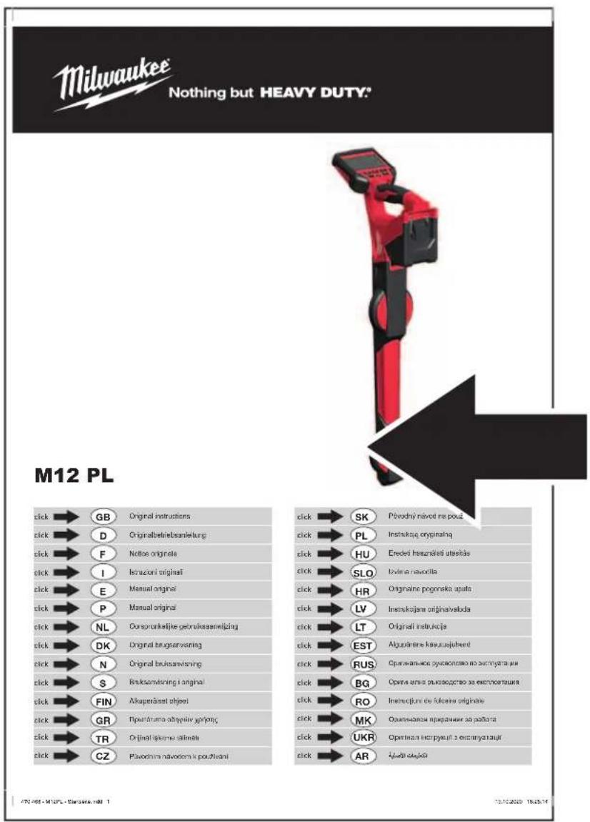
M12 PL-0C - Measuring equipment MILWAUKEE - Free user manual and instructions
Find the device manual for free M12 PL-0C MILWAUKEE in PDF.

| Product Type | Pipe locator for pipe inspection system |
| Brand | Milwaukee |
| Model | M12 PL-0C |
| Battery Voltage | 12 V (M12 system) |
| Weight (with battery) | 2.56 to 2.8 kg depending on battery capacity |
| Bluetooth Frequencies | 2402-2480 MHz, Bluetooth 4.0 |
| Display | LCD screen with bar graph, depth indicator, probe direction |
| Locating Modes | Sonde, Cable tracking (33 kHz, 83 kHz), Passive (50/60 Hz), Radio (15-27 kHz) |
| Main Functions | Sonde detection, push cable tracking, passive pipe locating, depth measurement, alignment indicator, self-diagnosis |
| Connectivity | Bluetooth for ONE-KEY app (locking, locating, LED flashing) |
| Power Supply | Milwaukee M12 lithium-ion battery (recommended M12B...) |
| Battery Life | Variable depending on battery; adjustable auto shut-off (1 to 15 min or never) |
| Operating Temperature | -18 °C to +50 °C |
| Backlight | Yes, adjustable |
| Speaker | Built-in with volume control and sound modes (FM, AM, Real) |
| Maintenance and Cleaning | Clean with a dry cloth; do not immerse; use only Milwaukee parts |
| Safety | Do not use on live parts; remove battery before maintenance; do not incinerate |
| Spare Parts and Repairability | Contact Milwaukee after-sales service; see warranty brochure |
| General Information | CE compliant; battery transport according to regulations; firmware update via Milwaukee website |
Frequently Asked Questions - M12 PL-0C MILWAUKEE
User questions about M12 PL-0C MILWAUKEE
0 question about this device. Answer the ones you know or ask your own.
Ask a new question about this device
Download the instructions for your Measuring equipment in PDF format for free! Find your manual M12 PL-0C - MILWAUKEE and take your electronic device back in hand. On this page are published all the documents necessary for the use of your device. M12 PL-0C by MILWAUKEE.
USER MANUAL M12 PL-0C MILWAUKEE
natural_image
Red and black handheld device with a digital display (no visible text or symbols)1 General informations....2
1.1 Additional safety and working instructions....2
1.2 Technical data 2
1.3 Specified conditions of use 2
1.4 Radio frequency interface requirements - related to European installation 2
1.5 EC-declaration of conformity....3
1.6 One-key™ 3
1.7 Batteries....3
1.8 Transporting lithium batteries....3
1.9 Maintenance....3
1.10 Symbols 4
2 Overview 5
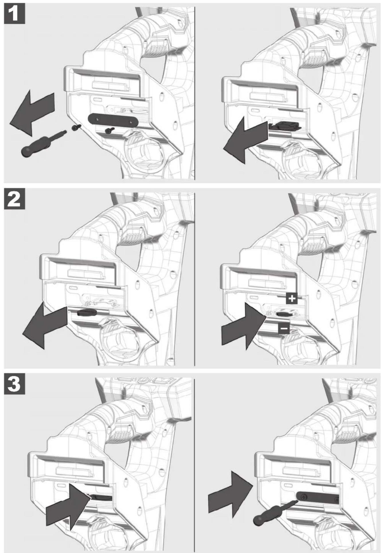
3 Installing and removing battery 6
4 Change ONEKEY battery 7
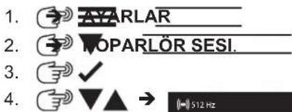
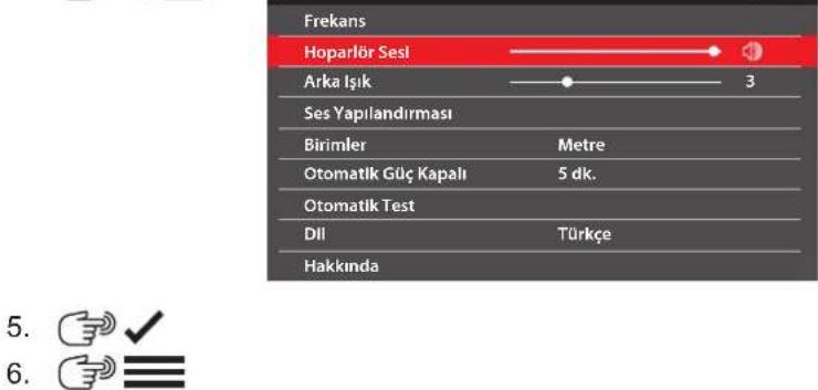
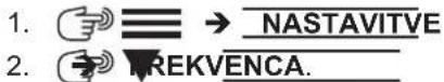
5 Setup....8
5.1 Power on/off 8
5.2 First time setup....8
5.3 Setup-symbols 8
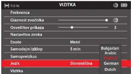
5.4 Language 8
5.5 Frequency 9
5.6 Speaker volume 9
5.7 Backlight....9
5.8 Sound configuration 10
5.9 Units 10
5.10 Auto power off 10
5.11 Self-test function 11
5.12 About screen.... 11
5.13 ONE-KEY 11
5.14 Battery Temperature.... 11
6 Sonde Locating 12
6.1 Navigating thePIPELINE LOCATOR menu 12
6.2 Sonde locate screens 12
6.3 Sonde Signal....13
6.4 Set the mode and frequency of the PIPELINE LOCATOR....13
6.5 Locating the Sonde 14
7 Push Cable and Line Locating 15
7.1 Passive versus active locating.... 15
7.2 Grounding Post 15
7.3 Applying the transmitter signal....16
7.4 The LINE TRACE Locate Screen....16
7.5 Tracing the Push Cable.... 17
8 Passive Locating - Power & Radio 19
8.1 What is passive locating? 19
8.2 Locating power or radio signals 19
9 Firmware Updates....21
1.1 Additional safety and working instructions
Always check the work area before beginning a job. Do not allow the tool to contact electrical, chemical, or moving hazards.
Do not try to replace the battery pack if the surface of the instrument is wet.
Do not dispose of used battery packs in the household refuse or by burning them. Milwaukee Distributors offer to retrieve old batteries to protect our environment.
Do not store the battery pack together with metal objects (short circuit risk).
Use only System M12 chargers for charging System M12 battery packs. Do not use battery packs from other systems.
Battery acid may leak from damaged batteries under extreme load or extreme temperatures. In case of contact with battery acid wash it off immediately with soap and water. In case of eye contact rinse thoroughly for at least 10 minutes and immediately seek medical attention.
Warning! To reduce the risk of fire, personal injury, and product damage due to a short circuit, never immerse your tool, battery pack or charger in fluid or allow a fluid to flow inside them. Corrosive or conductive fluids, such as seawater, certain industrial chemicals, and bleach or bleach containing products, etc., Can cause a short circuit.
This appliance is not intended to be used or cleaned by persons with reduced physical, sensory or mental capabilities, or lack of experience or knowledge, unless they have been given instructions concerning the safe use of the appliance by a person legally responsible for their safety. They should be supervised whilst using the appliance. Children shall not use, clean or play with this appliance, which when not in use should be secured out of their reach.

Chemical Burn Hazard. This device contains a lithium button/coin cell battery. A new or used battery can cause severe internal burns and lead to death in as little as 2 hours if swallowed or enters the body. Always secure the battery cover. If it does not close securely, stop using the device, remove the batteries, and keep it away from children. If you think batteries may have been swallowed or entered the body, seek immediate medical attention.
1.2 Technical data
Battery voltage 12 V
Weight according EPTA-Procedure 01/2014 (2.0 ... 6.0 Ah) ...... 2.56 ... 2.8 kg
Frequency band(s) of Bluetooth 2402-2480 MHz
Radio-frequency power 1.8 dBm
Bluetooth version 4.0 BT signal mode
Recommended ambient operating temperature ....-18 ....+50 °C
Recommended battery Type M12B...
Recommended charger Type ....C12C, M12C4, M12-18...
1.3 Specifi ed conditions of use
The PIPELINE LOCATOR is designed to locate the sonde position and trace the push cable of the Milwaukee PIPELINE INSPECTION SYSTEMS REEL.
Do not use this product in any other way as stated for normal use.
1.4 Radio frequency interface requirements - related to European installation
Note: This equipment has been tested and found to comply with the limits for a EN 300 440 v2.1.1 receiver Category 3.
These limits are designed to provide reasonable protection against harmful interference in a residential installation.
This equipment is sensitive to other equipment that intentionally generates, radio frequency energy in the 2402-2480MHz that may conduce to the instability to use the remote control on it. However there is no guarantee that interference will not occur in a particular installation. If this equipment suffer from the harmful interference from another radio device to radio this can be determined by turning the respective equipment off and on, the user is encouraged to try to correct the interference by one or more of the following measures:
- Turn off the disturbance equipment
- Increase the separation between the disturbance equipment
- Consult the dealer or an experienced radio technician for help
1.5 EC-declaration of conformity
Hereby, Techtronic Industries GmbH declares that the radio equipment type M12 PL is in compliance with Directive 2014/53/EU. The full text of the EU declaration of conformity is available at the following internet address: http://services.milwaukeeetool.eu.
1.6 One-key™
To learn more about the ONE-KEY functionality for this tool, please reference the Quick Start guide included with this product or go to www.milwaukeetool.com/one-key. To download the ONE-KEY app, visit the App Store or Google Play from your smart device.
Also, when the product experiences ESD, the Bluetooth communication will be disconnected. It needs to be reset manually to recover.
We considered the results to be within our minimum acceptable performance level according to EN 55014-2:2015 / EN 301489-1 V2.2.3/ EN 301489-17 V3.1.1.
One-key™ indicator
Solid Blue: Wireless mode is active and ready to be configured via the ONE-KEY™ app.
Blinking Blue: Tool is actively communicating with the ONE-KEY™ app.
Blinking Red: Tool is in security lockout and can be unlocked by the owner via the ONE-KEY™ app.
1.7 Batteries
Battery packs which have not been used for some time should be recharged before use.
Temperatures in excess of 50^ C ( 122^ F) reduce the performance of the battery pack. Avoid extended exposure to heat or sunshine (risk of overheating).
The contacts of chargers and battery packs must be kept clean.
For an optimum life-time, the battery packs have to be fully charged, after used.
To obtain the longest possible battery life remove the battery pack from the charger once it is fully charged.
For battery pack storage longer than 30 days:
Store the battery pack where the temperature is below 27^ C and away from moisture
Store the battery packs in a 30% - 50% charged condition
Every six months of storage, charge the pack as normal.
1.8 Transporting lithium batteries
Lithium-ion batteries are subject to the Dangerous Goods Legislation requirements.
Transportation of those batteries has to be done in accordance with local, national and international provisions and regulations.
- The user can transport the batteries by road without further requirements.
- Commercial transport of Lithium-Ion batteries by third parties is subject to Dangerous Goods regulations.
Transport preparation and transport are exclusively to be carried out by appropriately trained persons and the process has to be accompanied by corresponding experts.
When transporting batteries:
- Ensure that battery contact terminals are protected and insulated to prevent short circuit.
- Ensure that battery pack is secured against movement within packaging.
- Do not transport batteries that are cracked or leak.
Check with forwarding company for further advice
1.9 Maintenance
Use only Milwaukee accessories and spare parts. Should components need to be replaced which have not been described, please contact one of our Milwaukee service agents (see our list of guarantee/service addresses).
If needed, an exploded view of the tool can be ordered. Please state the machine type printed as well as the six-digit No. on the label and order the drawing at your local service agents or directly at: Techtronic Industries GmbH, Max-Eyth-Straße 10, 71364 Winnenden, Germany.
1.10 Symbols
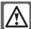
CAUTION! WARNING! DANGER!
Remove the battery pack before starting any work on the machine.

Please read the instructions carefully before starting the machine.
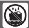
Do not allow the battery to contact corrosive or conductive fluid.
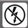
To prevent electric shock, do not allow product to contact live electrical parts.

Do not swallow the coin cell battery!
Do not dispose electric tools, batteries/rechargeable batteries together with household waste material. Electric tools and batteries that have reached the end of their life must be collected separately and returned to an environmentally compatible recycling facility. Check with your local authority or retailer for recycling advice and collection point.
V Volts
[EMPTY]
Direct current

European Conformity Mark

Ukraine Conformity Mark

EurAsian Conformity Mark
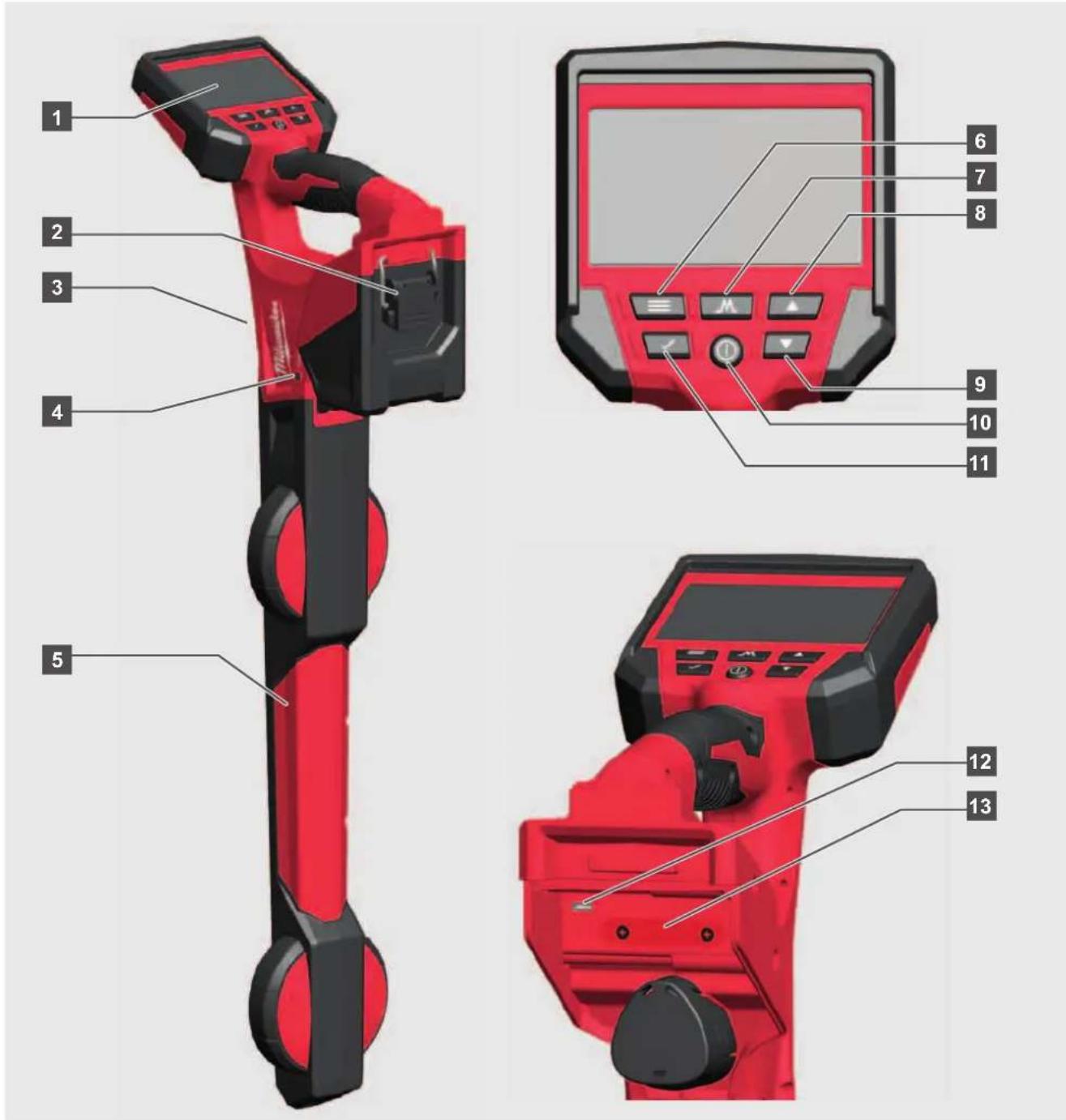
1 LCD
2 Battery compartment
3 Speaker
4 ONEKEY LED
5 Locator stem
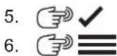
6 Menu button
7 Mode button
8 Up button
9 Down button
10 Power button
11 Select button
12 Mini USB port
13 ONEKEY battery compartment
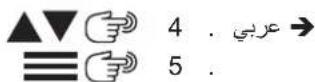
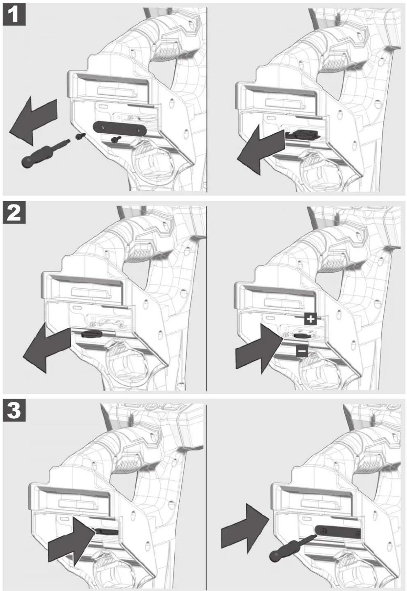
3 INSTALLING AND REMOVING BATTERY

4 CHANGE ONEKEY BATTERY
This section of the manual covers setting up the features and options of the PIPELINE LOCATOR.
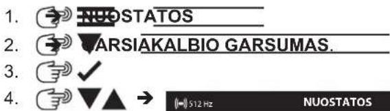
5.1 Power on/off
Press the POWER ⏻ button to power on the PIPELINE LOCATOR.
The buttons will illuminate, showing that the power is on.
Press the POWER Ⓐ button for 2 seconds to power off the PIPELINE LOCATOR.
The PIPELINE LOCATOR will shut off automatically after the time selected in the settings menu.
A signal sounds for 20 seconds, then shut off.
5.2 First time setup
All the settings are saved into the PIPELINE LOCATOR memory and will remain there until changed. The initial settings will set the FREQUENCIES, VOLUME, BACKLIGHT TIMERS, SOUND CONFIGURATION, UNITS OF MEASURE, POWER TIMER, and LANGUAGE
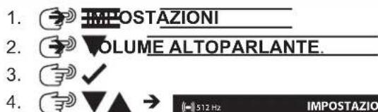
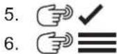
5.3 Setup-symbols
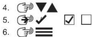
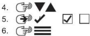
 | Press the button |
 | go to... |
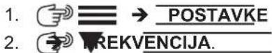
 | MENU button - enter the menu options. Also, use to step back (return) to the previous screen. |
 | MODE button - toggle through the selected locate modes and their selected frequencies |
 | UP and DOWN navigation button - move vertically through the menu and to lower and raise the sensitivity while locating. |
 | SELECT button - press to accept the menu options |
 | POWER button - turn on and off the PIPELINE LOCATOR |
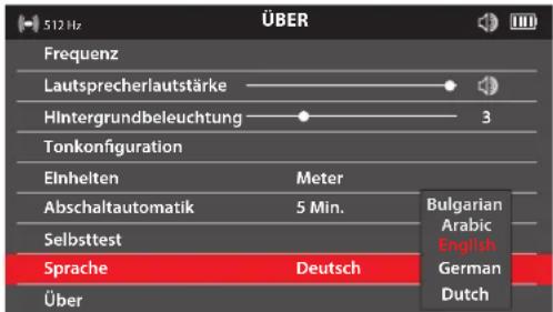
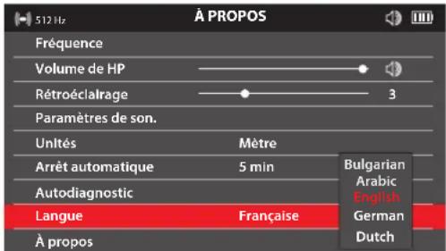
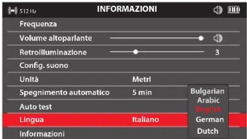
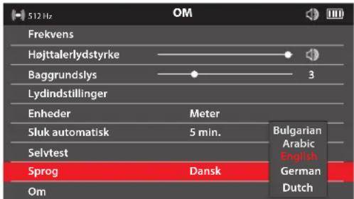
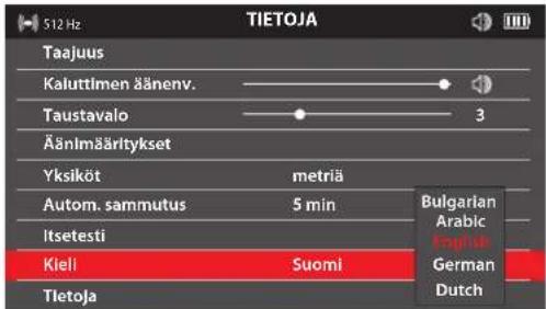
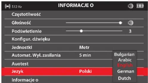
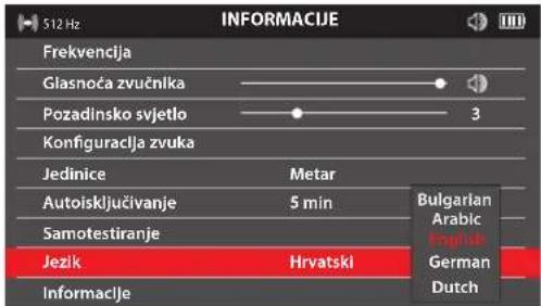
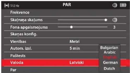
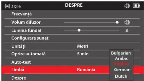
5.4 Language
It is recommended to set your LANGUAGE first so that the other menus can be easily read and understood.
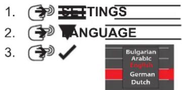

- English
5.
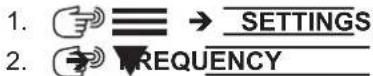
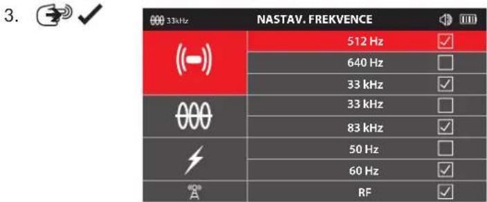
5.5 Frequency
The option sets the PASSIVE, ACTIVE, and SONDE frequencies.


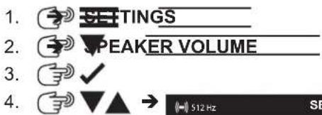
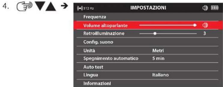
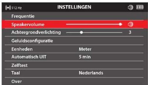
5.6 Speaker volume

5.7 Backlight
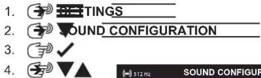
5.8 Sound configuration
FM - Frequency Modulated - The sound pitch changes with the signal strength AM - Amplitude Modulated - The sound volume changes with the signal strength Real - The sound is derived directly from the received signal
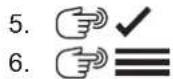
5.9 Units
5.10 Auto power off
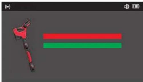
5.11 Self-test function
The SELF-TEST function confirms that the locator is operating within its set parameters.
The SELF-TEST should be run in an area free of interference from below ground or above ground utilities
- Keep the PIPELINE LOCATOR still while the SELF-TEST is running.

natural_image
3D rendered mechanical component with red and green horizontal bars, no text or symbols presentThe result will show a PASSED or FAILED screen
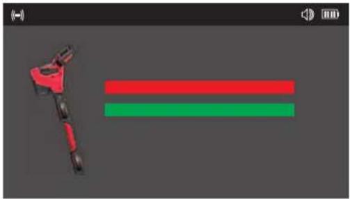
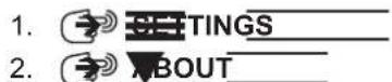
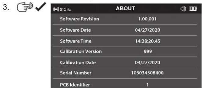
5.12 About screen
The ABOUT screen shows the locator's serial number, calibration, and software information. You may be asked to provide information from this screen when requesting technical support.
5.13 ONE-KEY
Functionalities for One-Key:
- Lock
- Unlock
- Find/blink LED
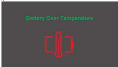
5.14 Battery Temperature
If the temperature reaches a high of 75^ C / 167^ F , this message will appear for 5 seconds, followed by the unit shutting down.
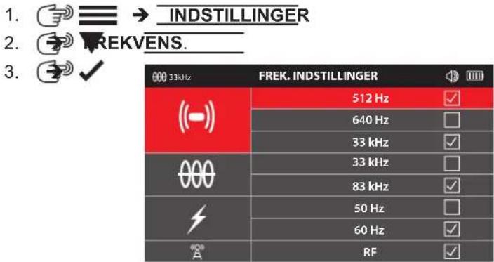
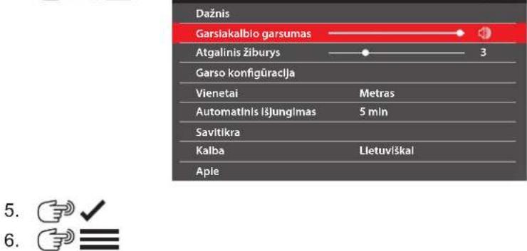
6.1 Navigating the PIPELINE LOCATOR menu
Repeatedly pressing the button will toggle through the selected locate modes and their selected frequencies.
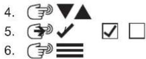
Alternatively, pressing and holding the M button will bring up the Shortcut menu. In this menu use the ▼▲ buttons to select the mode and its frequency to use, and then press the M button again. This will bring up that mode and frequency.
Pressing the ≡/ √ button will exit this screen and return to the previous screen.
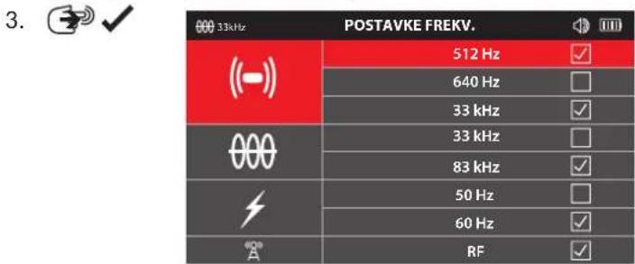
| FREQUENCIES | |
| ((-)) | 512 Hz |
| 640 Hz | |
| 33 kHz | |
| 000 | 33 kHz |
| 83 kHz | |
| 50 Hz | |
| 60 Hz | |
| RF | |
The shortcut menu screen.
6.2 Sonde locate screens
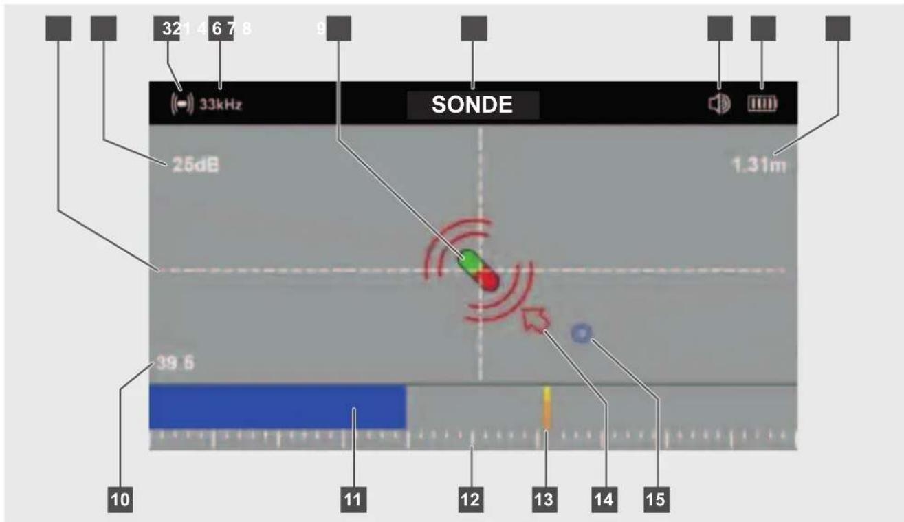
1 Crosshairs
2 Gain setting in dB
3 Sonde icon
4 Active sonde frequency
5 Sonde indicator
6 Sonde mode indicator
7 Speaker volume
8 Battery status
9 Depth to the Sonde
10 Bar graph percentage
11 Peak bar graph bar
12 Peak bar graph scale
13 Last peak indicator
14 Sonde direction arrow
15 Sonde forward or rear point
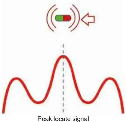
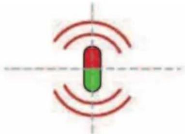
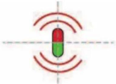
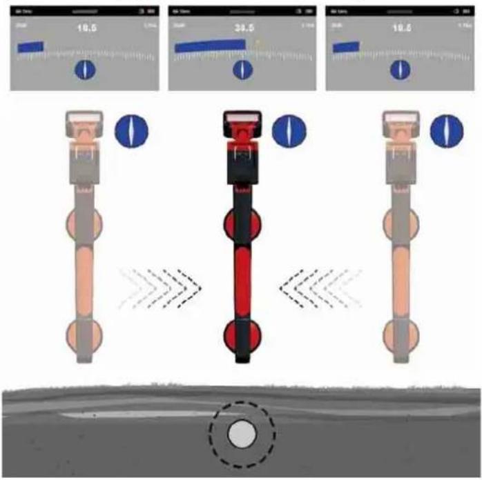
6.3 Sonde Signal
The sonde emits a large peak locate signal and two null points (forward or rear points) on each side of the peak. The deeper the sonde is underground, the further apart these two null points will be.
The screen of the PIPELINE LOCATOR displays the peak and null points as:
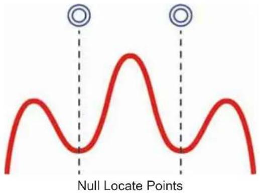
As the user approaches the Sonde, from either direction, the locator will pick up the rear or forward null locate point. The null locate points are identified by a blue double circle
After the null locate point, an arrow will appear directing the user toward the sonde location.
Following the arrow will lead the user over the peak locate signal where the sonde icon will appear.
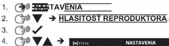
6.4 Set the mode and frequency of the PIPELINE LOCATOR
-
EREQUENCY
-
√
-
Make sure that the Sonde frequency matches sonde frequency set in the WIRELESS MONITOR or PIPELINE INSPECTION APP.
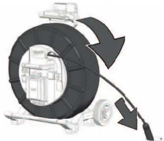
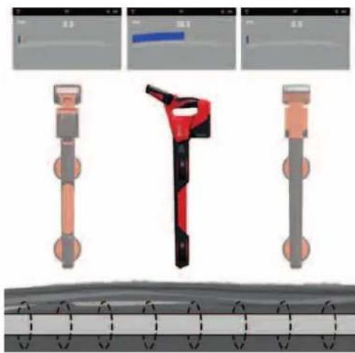
6.5 Locating the Sonde
- Activate the sonde of the PIPELINE INSPECTION REEL through the WIRELESS MONITOR or PIPELINE INSPECTION APP.
- Set the PIPELINE LOCATOR to sonde mode and set the frequency to match that of the PIPELINE INSPECTION REEL.
- Push the camera head into the pipe until it is level and zero out the distance counter
natural_image
Illustration of a mechanical device with a large tire and cable, showing motion arrows (no text or symbols)- Push the sonde 3 to 4m into the pipe.
- Walk slowly in the direction of the arrow.

natural_image
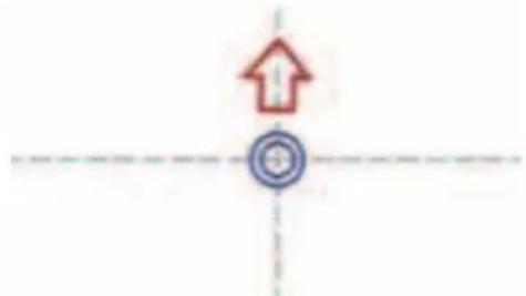
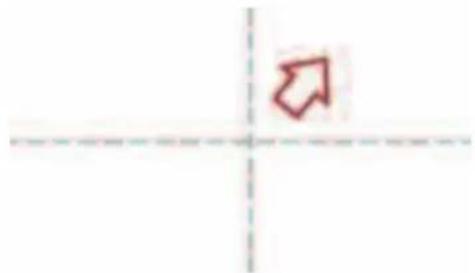
Simple red arrow pointing diagonally upward to the left of a dashed horizontal axis (no text or symbols)- The null point circle will appear on the screen, indicating the position of a null signal. Walk toward it and position it over the crosshairs.
natural_image
Simple diagram with a red upward arrow and a blue circular target symbol, intersected by dashed lines (no text or labels)- Walk slowly in the direction of the arrow until the sonde icon appears. Keeping the PIPELINE LOCATOR vertical, carry on walking toward the sonde until it is positioned on the crosshairs. The PIPELINE LOCATOR is now over the sonde.
natural_image
Simple diagram of a capsule-shaped object with red and green color bands, surrounded by concentric red wave lines (no text or symbols)7.1 Passive versus active locating
Active Passive
| Defi nition Active locating is generally used to trace and pinpoint a specifi c buried lineActive locating always requires a sonde or transmitter. | Used to mark the location of unidentifi ed buried lines to avoid them.Do not use to identify or trace specifi c lines. |
| Modes SondeLine trace 33kHz & 83kHz | Power: 50/60HzRadio: 15 kHz – 27 kHz |
| Source PIPELINE INSPECTION REELSWIRELESS MONITORPIPELINE INSPECTION APPSondes | Power* - transmission & distribution networksRadio* - high power, low frequency (LF) communication transmitting towers. |
| When to use Use to trace, identify & pinpoint a buried line.When a depth measurement is required. | Search for unknown buried lines when applying a transmitter signal is not practical.For small, localized digging (planting a fencepost or road sign).A last check before digging. |
* Buried pipes and cables act as antennas that re-radiate the signal.
Radio signals travel further distances if both ends of the utility are grounded.

Always call before you dig and follow local, state, or national regulations and your company's safety and work practices.
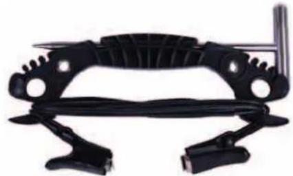
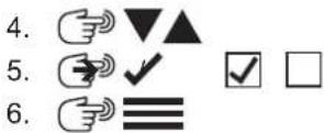
7.2 Grounding Post
The grounding post must be used while using the LINE TRACE feature to trace push cable. The CONTROL HUB must be grounded to close the current loop to send out a good locate signal. Use the supplied grounding cable assembly with ground stake to ground the CONTROL HUB to earth.
natural_image
Black mechanical clamp or bracket component with no visible text or symbols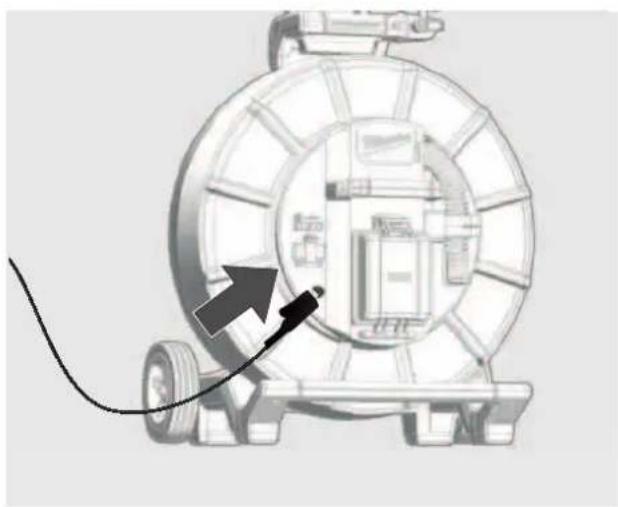
natural_image
Diagram of a mechanical device with a cable and directional arrow, no visible text or symbols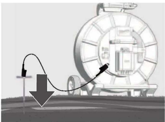
natural_image
Illustration of a mechanical device with a curved arrow indicating motion, no text or symbols present7.3 Applying the transmitter signal
In the Milwaukee WIRELESS MONITOR or Milwaukee PIPELINE INSPECTION APP:
- Select LINE TRACE press the navigation dial.
On the PIPELINE LOCATOR
- Select a LINE TRACE frequency of 33kHz or 83kHz.
| 33kHz | FREQUENCIES |
| 512 Hz | |
| 640 Hz | |
| 33 kHz | |
| 33 kHz | |
| 83 kHz | |
| 50 Hz | |
| 60 Hz | |
| *A | RF |
| 83kHz | FREQUENCIES |
| (--) | 512 Hz |
| 640 Hz | |
| 33 kHz | |
| 000 | 33 kHz |
| 83 kHz | |
| 50 Hz | |
| 60 Hz | |
| A | RF |
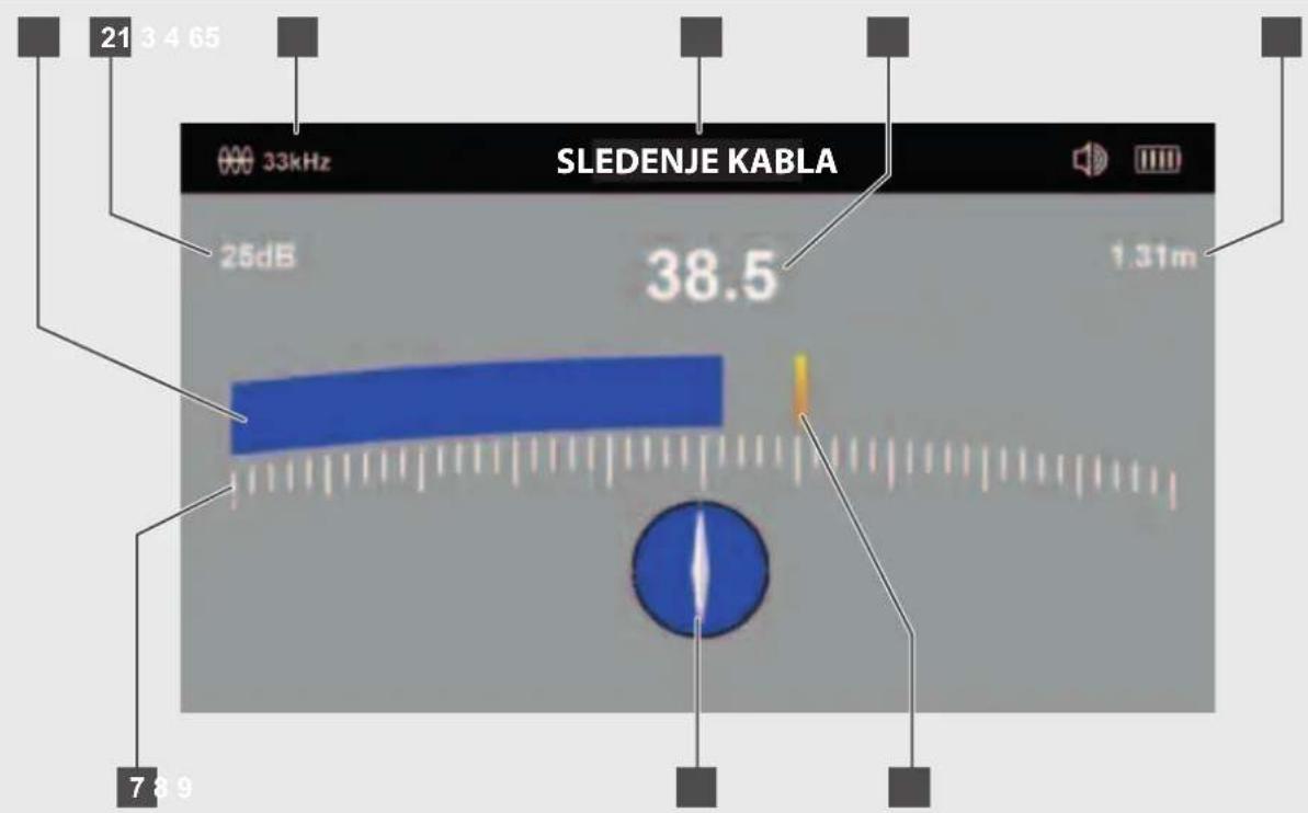
7.4 The LINE TRACE Locate Screen
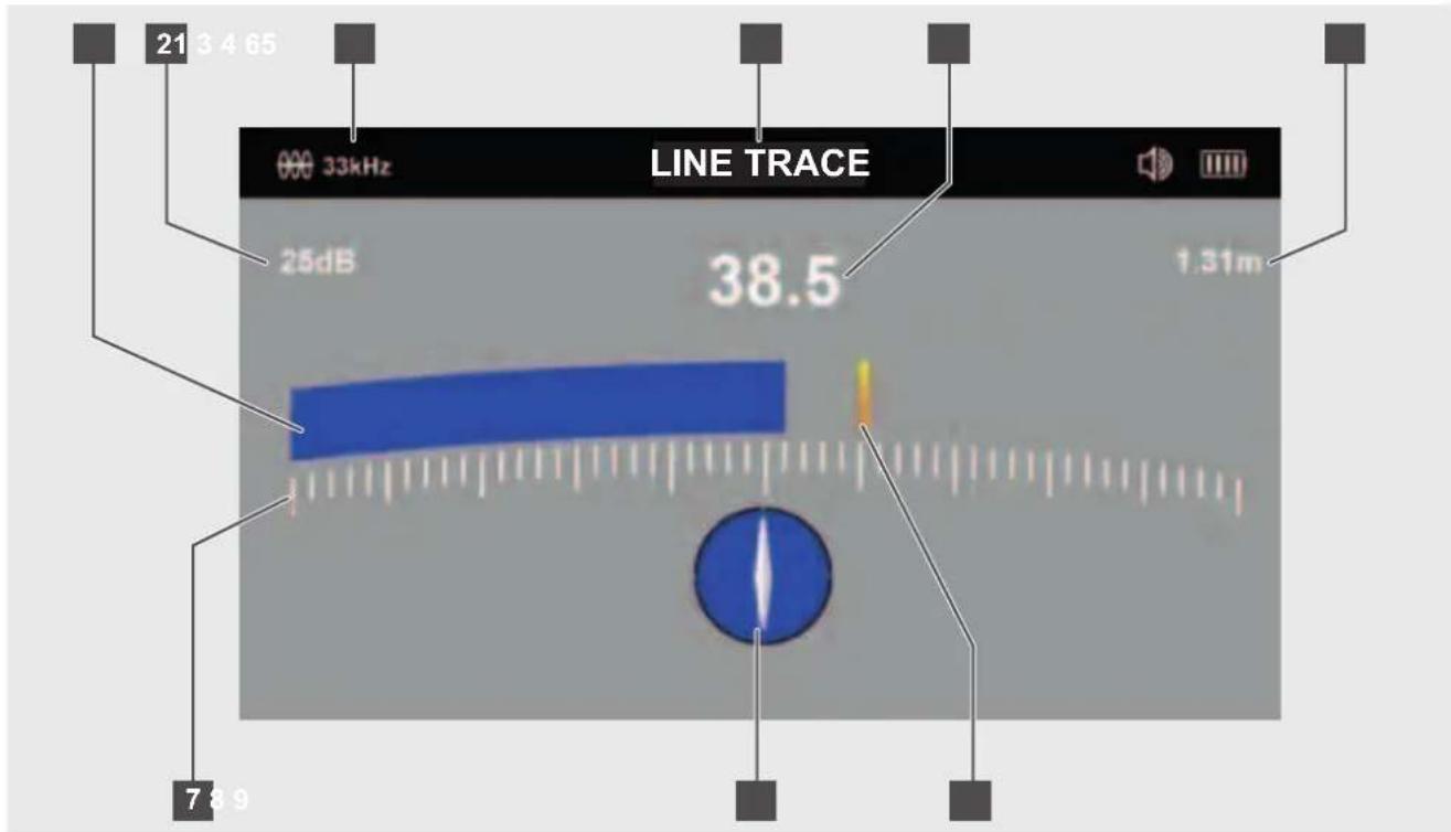
1 Bar graph (mirrors #5 signal strength)
2 Gain setting in dB
3 Active line frequency
4 PIPELINE LOCATOR current mode
5 Signal strength (mirrors #1 bar graph)
6 Depth of cover
7 Bar graph scale
8 Line direction indicator
9 Last peak indicator
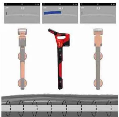
The PIPELINE LOCATOR is a peak locator. The antenna configuration provides a "peak" or maximum signal response when directly on top of the sonde or push cable. On the PIPELINE LOCATOR display, the signal strength #5 and bar graph #1 will be at their maximum, or peak.
When at its peak, the last peak indicator, #9 will be left at the peak position, as a reference point before the bar graph and signal strength decline.
The line direction indicator, #8, will turn from a clear background to solid blue background when in line with the push cable.
The signal strength (#5) and bar graph (#1) at their highest when over the utility.
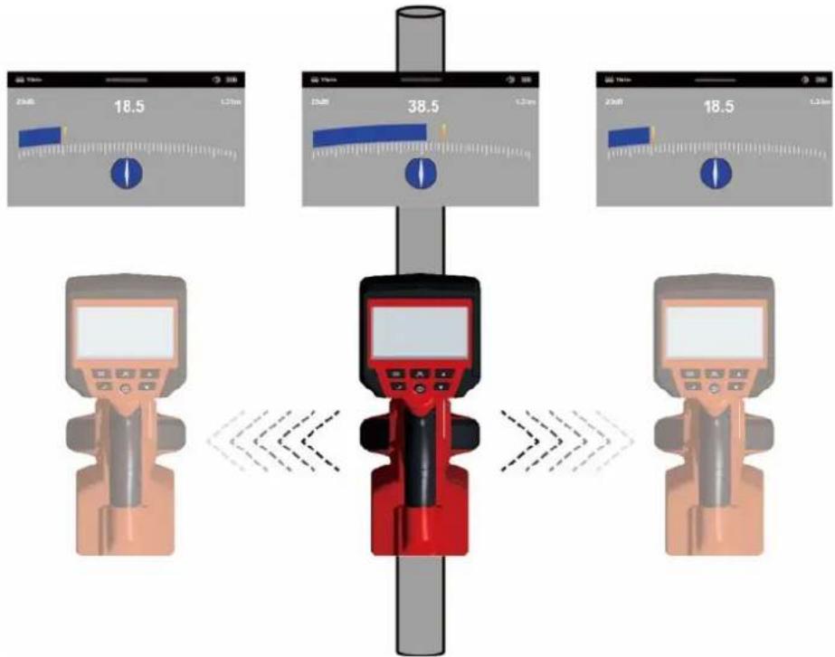
7.5 Tracing the Push Cable
- Switch on the PIPELINE LOCATOR and use the button to put the PIPELINE LOCATOR into the LINE TRACE mode with the frequency matching the Milwaukee WIRELESS MONITOR or Milwaukee PIPELINE INSPECTION APP.
Line Direction Indicator - In the presence of a locate signal, the line direction indicator will align itself parallel to the push cable being located. This ensures that the operator is aware of the direction of the push cable.
- Find the push cable direction - When the line direction indicator is in line with the PIPELINE LOCATOR's handle, this is the Indication of the direction of the push cable.
When the locator is in line with the push cable, the white section of the line direction indicator will turn blue.
Pivot the PIPELINE LOCATOR and rotate it on its axis while watching the line direction indicator. When the handle is in line with the push cable, the line direction indicator will flash and turn blue.
Pivot the Locator and rotate it on its axis while watching the line direction indicator.
-
Next, adjust the sensitivity control, using the buttons, so that the display indicates approximately 50%.
-
Keep the PIPELINE LOCATOR vertical, and in line with the push cable, move to the right side slightly. If the bar graph increases, you are moving toward the rod. If it decreases, you are walking away from it.
Move the locator side to side while looking for maximum response from the bar graph
- Move toward the push cable until a maximum signal is achieved. It may be necessary to reduce the sensitivity to keep the bar graph on the scale. This is normal and should be expected. Try to keep the PIPELINE LOCATOR vertical and avoid swinging it as this may create false readings.
When on top of the push cable the bar graph will be at its peak and the line direction indicator will turn solid blue with a white line indicating the direction of the push cable
- Move the locator side to side to ensure a maximum signal is detected. Use the peak level indicator to assist.
8.1 What is passive locating?
Passive locating refers to the process of detecting signals that „naturally“ occur on pipes and cables. These tend to fall into two categories, radio signals, and power signals.
Sources of passive locate signals:
natural_image
Illustration of power transmission towers with signal waves and a cylindrical conductor on a green field (no text or symbols)Power signals
These signals are 50/60Hz signals created by power transmission cables. When electrical power is distributed throughout the network, some of the power finds its way back to the power station via the ground. These stray currents can jump onto pipes and cables and also create power signals. Note that there has to be electrical current flowing to create a detectable signal. For instance, a live cable that is not in use may not radiate a detectable signal. Also, a very well balanced cable, i.e., the same amount of current flowing in live and neutral, will cancel out and may not create a signal. In practice, this is unusual as there are usually enough imbalances in the cable to create a good detectable signal.
Radio signals
These signals created by low-frequency radio transmitters that are used for broadcasting and communications. When the signals cross a long conductor such as a pipe or cable, the signals are re-radiated. It is these re-radiated signals that can be detected by the RF mode.
8.2 Locating power or radio signals
- Switch on the PIPELINE LOCATOR and use the button to enter the PASSIVE OR RF mode.
-
Hold the PIPELINE LOCATOR vertically and away from likely positions of cables or pipes.
-
Adjust the sensitivity using the ▼▲ buttons so that the bar graph reading is just starting to show some movement. Note that the line direction indicator feature is not available for the Power or Radio modes.
NOTE
Note that there will be no sound from the speaker until the meter reading is above approximately 10% of full scale.
- Keeping the PIPELINE LOCATOR vertical, walk across the area to be checked, keeping the orientation so that the locator stem is in line with the direction of walking (See diagram above).
flowchart
graph TD
    A["Valve 1"] --> B["Directional Control Valve"]
    B --> C{Valve 2}
    C -->|Yes| D["Return Line"]
    C -->|No| E["Return Line"]
    D --> F["Pressure Gauge"]
    E --> F
    F --> G["Return Line"]
    G --> H["Feedback Loop"]
    H --> I["Return Line"]
    I --> J["Return Line"]
    J --> K["Return Line"]
    K --> L["Return Line"]
    L --> M["Return Line"]
    M --> N["Return Line"]
    N --> O["Return Line"]
    O --> P["Return Line"]
    P --> Q["Return Line"]
    Q --> R["Return Line"]
    R --> S["Return Line"]
    S --> T["Return Line"]
    T --> U["Return Line"]
    U --> V["Return Line"]
    V --> W["Return Line"]
    W --> X["Return Line"]
    X --> Y["Return Line"]
    Y --> Z["Return Line"]
-
Continue in a grid across the area.
-
If at any time, the meter reading starts to increase, carefully move the locator side to side to detect the maximum signal. Use the peak level indicator to help confirm the correct position.
Move the locator side to side while looking for maximum response from the bar graph
natural_image
Three-panel diagram showing mechanical components with no visible text or symbols-
Rotate the PIPELINE LOCATOR on its axis to obtain the maximum signal. The PIPELINE LOCATOR is now directly over the line and with the stem across the line.
-
The direction can also be found by rotating until the smallest signal is detected. The stem is then in line with the cable/pipe.
-
Continue to locate the position of the line at regular intervals until its course is known through the target area.
9 FIRMWARE UPDATES
Before updating a system, go to SETTINGS → ABOUT, look at the ABOUT screen and make a note of the current fi rmware revisions.
For any Firmware updates please visit our service website https://www.milwaukeetool.eu/.
click
470-468-M12PL-SanSera.no 1
73.10.2020 18:25:14
INHALT
natural_image
3D rendered red and green mechanical parts against a gray background, no text or symbols visiblenatural_image
Abstract red wavy line diagram with two vertical dashed lines and two circular markers above the curve (no text or symbols)Nullpunkte
Peak-Ortungssignal
natural_image
Illustration of a tire roller being pulled by a cable, with arrows indicating speed (no text or symbols)natural_image
Simple red arrow pointing diagonally upward on a white background with dashed and solid lines (no text or symbols)natural_image
Simple diagram with a red upward arrow and a blue circular target symbol, intersected by dashed lines (no text or labels)natural_image
Simple diagram of a capsule with red and green color scheme, surrounded by concentric red wave lines (no text or symbols)natural_image
Black plastic mechanical clamp or bracket component (no visible text or symbols)
natural_image
Diagram of a mechanical device with a cable and arrow pointing to a component (no text or symbols)
natural_image
Illustration of a pipeline system with a downward arrow and cable, no text or symbols present7.3 Sendesignal verwenden
natural_image
Illustration of transmission towers and a cylindrical conductor on a green field, with dashed circular wave patterns around them (no text or symbols)Leistungssignale
natural_image
Three-panel diagram showing mechanical components with no visible text or symbols5 Configuration....8


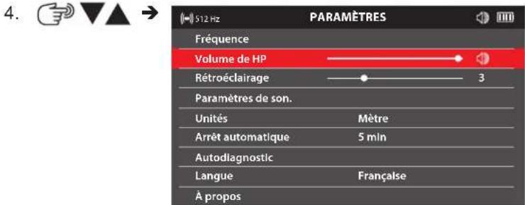
5.6 Volume de HP
-
PARAMÊTRES
-
VOLUME DE HP.
-
√
natural_image
3D rendered red and green mechanical parts against a gray background (no text or symbols)natural_image
Abstract red wavy line diagram with two circular markers above it, no text or symbols presentnatural_image
Black plastic mechanical clamp or bracket component (no visible text or symbols)
natural_image
Diagram of a mechanical device with a cable and arrow pointing to a component (no text or symbols)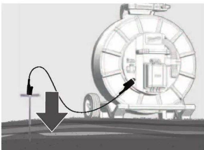
natural_image
Diagram showing a mechanical device connected to a cable with a downward arrow, no text or symbols presentnatural_image
Illustration of transmission towers and a cylindrical conductor on a green field, with dashed circular wave patterns around them (no text or symbols)natural_image
Three-panel diagram showing a red-handled tool interacting with a mechanical component, displayed in three views (no text or symbols)Peso secondo la procedura EPTA 01/2014 (2,0 ... 6,0 Ah) ...... 2.56 ... 2.8 kg
5.6 Volume altoparlante
natural_image
3D rendered image of a red and green object resembling a stylized tool or device, with no visible text or symbols.natural_image
Abstract red wavy line diagram with two vertical dashed circles above, no text or symbols presentnatural_image
Illustration of a car tire being pulled by a cable, with arrows indicating speed (no text or symbols)natural_image
Simple red arrow pointing diagonally upward to the left of a dashed coordinate axis (no text or symbols)natural_image
Simple red arrow pointing diagonally upward to the left of a dashed coordinate axis (no text or symbols)natural_image
Diagram of a capsule-shaped object with red and green color coding, surrounded by concentric red wave patterns (no text or symbols)natural_image
Black plastic mechanical component with attached clamping bracket (no text or symbols visible)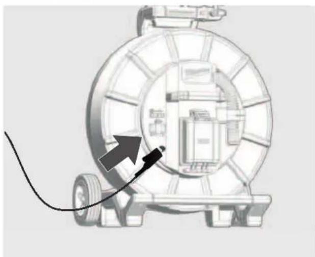
natural_image
Diagram of a mechanical device with a cable and arrow indicating direction (no text or symbols)
natural_image
Diagram of a pipeline system with a curved pipe passing through a large cylindrical device, showing flow direction (no text or symbols)natural_image
Illustration of transmission towers and a cylindrical conductor on a green field, with dashed circular wave patterns around them (no text or symbols)Segnali di potenza
natural_image
Three-panel illustration showing a red-handled tool with orange handle and black buttons, alongside three views of a mechanical component (no text or symbols)natural_image
3D rendered red and green mechanical parts against a gray background (no text or symbols)natural_image
Abstract red wavy line diagram with two circular markers above it, no text or symbols presentnatural_image
Illustration of a tire roller being pulled by a cable, with arrows indicating speed (no text or symbols)natural_image
Simple red arrow pointing diagonally upward to the left of a dashed coordinate axis (no text or symbols)natural_image
Simple red arrow pointing diagonally upward to the left of a dashed coordinate axis (no text or symbols)natural_image
Diagram of a capsule-shaped object with red and green segments, surrounded by concentric red wave patterns (no text or symbols)natural_image
Black mechanical clamp device with multiple arms and mounting holes (no visible text or symbols)
natural_image
Diagram of a mechanical device with a cable and directional arrow, no visible text or symbols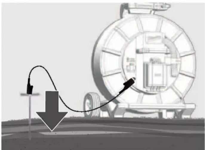
natural_image
Illustration of a mechanical device with a curved arrow and downward arrow, no visible text or symbolsnatural_image
Illustration of transmission towers and a cylindrical conductor on a green field, with dashed circular wave patterns around them (no text or symbols)Señales de potencia
natural_image
Three-panel diagram showing a red-handled tool interacting with a mechanical component, displayed in three views (no text or symbols)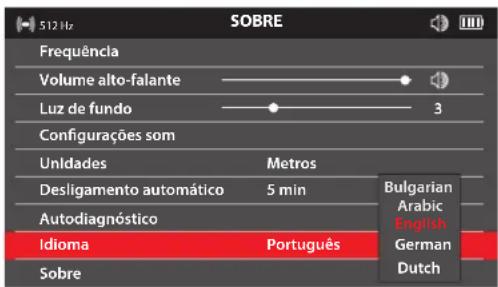


natural_image
3D rendered red and green object with no visible text or symbolsnatural_image
Abstract red wavy line diagram with two vertical dashed circles above it, no text or symbols presentnatural_image
Illustration of a tire roller being pulled by a cable, with arrows indicating motion direction (no text or symbols)natural_image
Simple red arrow symbol pointing diagonally upward to the left, intersected by dashed lines (no text or labels)natural_image
Simple red arrow pointing diagonally upward to the left of a dashed horizontal line (no text or symbols)natural_image
Simple diagram of a capsule-shaped object with red and green color bands, surrounded by concentric red wave lines (no text or symbols)natural_image
Black mechanical clamp device with attached clamps and a handle (no text or symbols visible)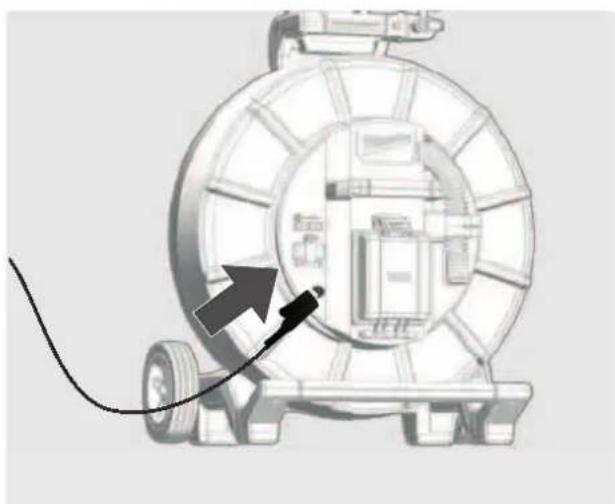
natural_image
Diagram of a mechanical device with a cable and directional arrow, no visible text or symbols
natural_image
Illustration of a pipeline system with a downward arrow and cable, next to a large cylindrical device (no text or symbols)7.3 Utilizar o sinal transmitido
7.5 Rastrear o cabo de deslize
natural_image
Illustration of transmission towers and a cylindrical device on a green field, with dashed circular wave patterns around them (no text or symbols)Sinais de potência
natural_image
Three-panel illustration showing a red-handled tool with orange handle and gray base, alongside three zoomed-in views (no text or symbols)OPGELET! WAARSCHUWING! GEVAAR!


- NODRLANDS
5.
5.5 Frequentie


5.6 Speakervolume
natural_image
Red robotic arm icon next to a horizontal bar with green and red stripes (no text or symbols)natural_image
Abstract red wavy line diagram with two circular markers above it, no text or symbols presentnatural_image
Illustration of a car tire being pulled by a cable, with arrows indicating speed (no text or symbols)natural_image
Simple red arrow pointing diagonally upward on a white background with dashed cross lines (no text or symbols)natural_image
Simple red arrow pointing diagonally upward to the left of a dashed coordinate axis (no text or symbols)natural_image
Simple diagram of a capsule-shaped object with red and green color bands, surrounded by concentric red circles (no text or symbols)natural_image
Black mechanical clamp device with attached clamps and a handle (no text or symbols visible)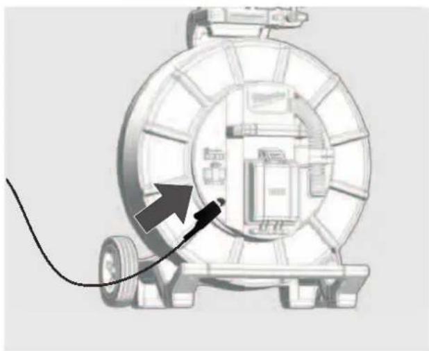
natural_image
Diagram of a mechanical device with a cable and directional arrow, no visible text or symbols
natural_image
Diagram showing a mechanical device with a curved cable and directional arrow, no text or symbols presentnatural_image
Illustration of transmission towers and a cylindrical antenna on a green field, with dashed circular paths indicating signal propagation (no text or symbols)Vermogenssignalen
natural_image
Three-panel illustration of a red-handled tool with orange and gray components, shown from different angles (no text or symbols)1 General information....2
4.
5.
5.5 Frekvens
Under dette menupunkt kan man indstille frekvensen for driftsmåderne PASSIV, AKTIV eller SONDE.
natural_image
3D rendered image of a red robotic arm and two horizontal colored bars (red and green) on a gray background, no text or symbols present.Resultatet af testen vises på displayet som BESTÅET eller IKKE BESTÅET.
5.12 Meuside OM
natural_image
Abstract red wavy line diagram with two circular markers above it, no text or symbols presentnatural_image
Illustration of a mechanical device with a large coil and directional arrows indicating motion or force (no text or symbols)-
Skub sonden 3 til 4 meter ind i røret.
-
Gå langsomt i pilens retning.
-
Skub sonden 3 til 4 meter ind i røret.
- Gå langsomt i pilens retning.

natural_image
Simple red arrow symbol pointing diagonally upward on a white background with dashed lines (no text or labels)natural_image
Simple red arrow symbol pointing diagonally upward to the left of a dashed horizontal line (no text or labels)natural_image
Simple diagram of a capsule-shaped object with red and green color bands, surrounded by concentric red wave lines (no text or symbols)natural_image
Black mechanical clamp or bracket component with no visible text or symbols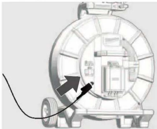
natural_image
Diagram of a mechanical device with a cable and arrow pointing to a component (no text or symbols)
natural_image
Illustration of a mechanical device with a curved pipe and arrow, no visible text or symbolsnatural_image
Illustration of transmission towers and a cylindrical conductor on a green field, with dashed circular wave patterns around them (no text or symbols)Kapacitetssignaler
natural_image
Three-panel illustration showing a red-handled tool with orange handle and gray base, alongside three zoomed-in views (no text or symbols)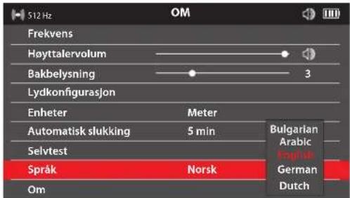
natural_image
Red and green horizontal bars on a gray background, no text or symbols presentTestresultatet vises på displayet som BESTÄTT eller IKKE BESTÄTT.
5.12 Menyside OVER
natural_image
Abstract red wavy line diagram with two circular markers above it, no text or symbols presentnatural_image
Illustration of a mechanical device with a large tire and cable, showing motion arrows (no text or symbols)- Skyv sonden 3 til 4 meter inn i røret.
- Gå langsomt i pilens retning.

natural_image
Simple red arrow pointing diagonally upward to the left of a dashed coordinate axis (no text or symbols)- Nullpunktsirkelen kommer til syne på displayet og viser posisjonen til et nullsignal. Gå imot dette punktet og fokuser det i trådkorset.
natural_image
Simple red arrow pointing diagonally upward to the left of a dashed vertical line (no text or symbols)natural_image
Diagram of a capsule-shaped object with red and green color coding, surrounded by concentric red wave patterns (no text or symbols)natural_image
Close-up of a black plastic clamp or bracket component (no visible text or symbols)
natural_image
Diagram of a mechanical device with a cable and arrow pointing to a component (no text or symbols present)
natural_image
Illustration of a mechanical device with a curved arrow indicating motion, no text or symbols presentnatural_image
Illustration of transmission towers and a cylindrical device on a green field, with dashed circular wave patterns around them (no text or symbols)Eff ektsignaler
natural_image
Three-panel illustration of a red-handled tool with orange and gray components, shown from different angles (no text or symbols)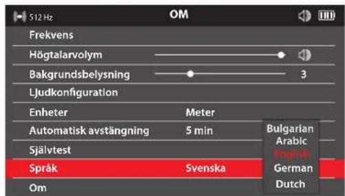
natural_image
3D model of a red and green vehicle with no visible text or symbolsTestet anges som GODKÄNT eller MISSLYCKAT på displayen.
5.12 Menysidan OM
natural_image
Abstract red wavy line diagram with two circular markers above it, no text or symbols presentPeak-lokaliseringssignal
natural_image
Illustration of a mechanical device with a large coil and directional arrows indicating motion or force (no text or symbols)natural_image
Simple red arrow pointing diagonally upward to the left of a dashed coordinate axis (no text or symbols)natural_image
Simple red arrow pointing diagonally upward on a white background with dashed lines (no text or symbols)natural_image
Diagram showing concentric red wave patterns around a central green capsule (no text or symbols)natural_image
Black plastic mechanical clamp or bracket component (no visible text or symbols)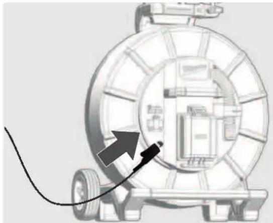
natural_image
Diagram of a mechanical device with a cable and arrow pointing to a component (no text or symbols present)
natural_image
Illustration of a mechanical device with a curved pipe and arrow indicating motion, no text or symbols presentnatural_image
Illustration of transmission towers and a cylindrical conductor on a green field, with dashed circular wave patterns around them (no text or symbols)Eff ektsignaler
natural_image
Three-panel illustration showing a red-handled tool with orange handle and black buttons, alongside three views of a mechanical component (no text or symbols)Paino EPTA-menettelyn 01/2014mukaan (2,0 ... 6,0 Ah) ...... 2.56 ... 2.8 kg


natural_image
Top-down view of a red and green vehicle model against a gray background (no text or symbols)natural_image
Abstract red wavy line diagram with two circular markers above it, no text or symbols presentnatural_image
Illustration of a mechanical device with a large tire and cable, showing a downward arrow indicating motion or pressure (no text or symbols present)natural_image
Simple red arrow symbol pointing diagonally upward to the left of a dashed coordinate axis (no text or labels)natural_image
Simple red arrow pointing diagonally upward to the left of a dashed coordinate axis (no text or symbols)natural_image
Diagram of a capsule-shaped object with red and green color coding, surrounded by concentric red wave patterns (no text or symbols)natural_image
Close-up of a black plastic clamp or bracket component (no visible text or symbols)
natural_image
Diagram of a mechanical device with a cable and arrow pointing to a component (no text or symbols)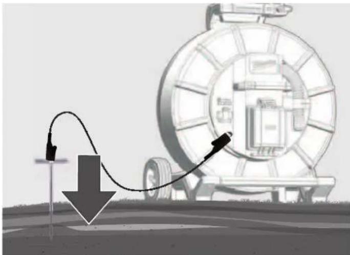
natural_image
Illustration of a mechanical device with a curved arrow indicating motion, no text or symbols presentnatural_image
Illustration of transmission towers and a cylindrical conductor on a green field, with dashed circular wave patterns around them (no text or symbols)Tehosignaalit
natural_image
Three-panel illustration of a red-handled tool with orange and gray components, shown from different angles (no text or symbols)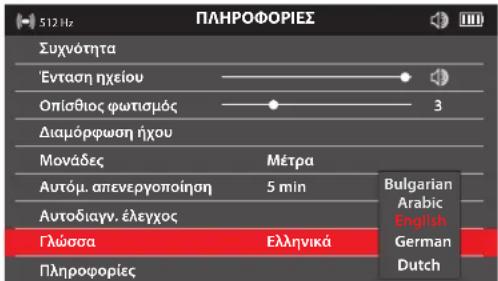
natural_image
Red robotic arm icon next to a horizontal bar with green and red stripes (no text or symbols)natural_image
Abstract red wavy line diagram with two vertical dashed circles above, no text or symbols presentnatural_image
Illustration of a mechanical device with a large spool and directional arrows indicating motion or flow (no text or symbols)natural_image
Simple red arrow pointing diagonally upward to the left of a dashed horizontal line (no text or symbols)natural_image
Simple red arrow pointing diagonally upward to the left of a dashed horizontal line (no text or symbols)natural_image
Diagram showing concentric red and green wave patterns around a central vertical bar (no text or symbols)natural_image
Illustration of transmission towers and a cylindrical antenna on a green field, with no visible text or symbols.Σήματα ισχύος
natural_image
Three-panel illustration showing a red-handled tool with orange handle and black buttons, alongside three views of a mechanical component (no text or symbols)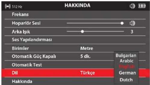


5.6 Hoparlör Sesi
natural_image
3D rendered red and green mechanical parts against a gray background (no text or symbols)natural_image
Abstract red wavy line diagram with two circular markers above it, no text or symbols presentnatural_image
Illustration of a mechanical device with a coiled cable and directional arrows indicating motion or flow (no text or symbols)natural_image
Simple red arrow symbol pointing diagonally upward on a white background with dashed cross lines (no text or labels)natural_image
Simple red arrow symbol pointing diagonally upward to the left of a dashed coordinate axis (no text or labels)natural_image
Simple diagram of a capsule with red and green color segments, surrounded by concentric red wave lines (no text or symbols)7 İTTIRMELI KABLONUN VE HATTIN YERINI TESPIT ETMEK
natural_image
Black plastic clamp bracket with metal clamps and a handle (no text or symbols visible)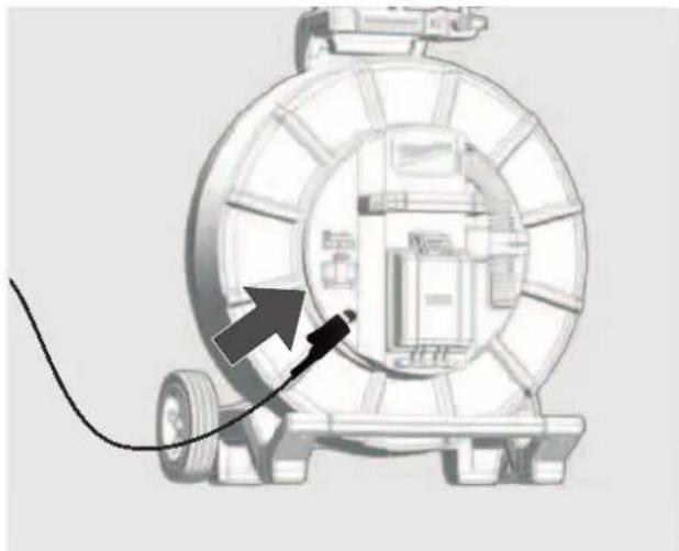
natural_image
Diagram of a mechanical device with a cable and directional arrow, no visible text or symbols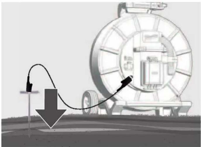
natural_image
Illustration of a pipeline system with a curved pipe and directional arrow, no text or symbols presentnatural_image
Illustration of transmission towers and a cylindrical conductor on a green field, with dashed circular wave patterns around them (no text or symbols)Güç sinyalleri
natural_image
Three-panel illustration of a red-handled tool with orange and gray components, shown from different angles (no text or symbols)
4.
5.
5.4 Frekvence
natural_image
3D rendered red and green mechanical components on a gray background (no text or symbols)natural_image
Abstract red wavy line diagram with two circular markers above it, no text or symbols presentnatural_image
Diagram of a mechanical device with a large tire and cable, showing directional arrows indicating motion or flow (no text or symbols present)natural_image
Simple red arrow symbol pointing diagonally upward to the left of a dashed coordinate axis (no text or labels)natural_image
Simple red arrow symbol pointing diagonally upward to the left of a dashed horizontal line (no text or labels)natural_image
Simple diagram of a capsule-shaped object with red and green color bands, surrounded by concentric red wave lines (no text or symbols)natural_image
Black mechanical clamp device with multiple arms and mounting holes (no visible text or symbols)
natural_image
Diagram of a mechanical device with a cable and directional arrow, no visible text or symbols
natural_image
Illustration of a mechanical device with a curved arrow indicating motion, no text or symbols presentnatural_image
Illustration of transmission towers and a cylindrical conductor on a green field, with dashed circular wave patterns around them (no text or symbols)Výkonové signály
natural_image
Three-panel illustration showing a red-handled tool interacting with a mechanical component, with no visible text or symbols.
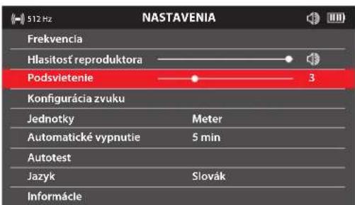
5.5 Hlasitost' reproduktora
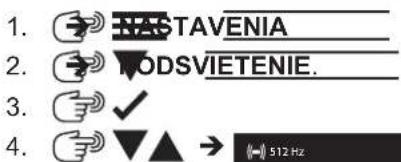
5.6 Podsvietenie
natural_image
3D model of a red car with two horizontal colored bars (red and green) on a gray background, no text or symbols present.natural_image
Abstract red wavy line diagram with two circular markers above it, no text or symbols presentnatural_image
Illustration of a mechanical device with a large tire and cable, showing motion arrows (no text or symbols)- Sondu zasuňte 3 až 4 metre do rúry.
- Pomaly chod'te v smere šípky.

natural_image
Simple red arrow symbol pointing diagonally upward on a white background with dashed lines (no text or labels)natural_image
Simple red arrow pointing diagonally upward to the left of a dashed coordinate axis (no text or symbols)natural_image
Simple diagram of a capsule-shaped object with red and green color bands, surrounded by concentric red wave lines (no text or symbols)7.1 Pasívne a aktivne navigovanie
Aktívne Pasívne
natural_image
Black plastic mechanical clamp or bracket component (no visible text or symbols)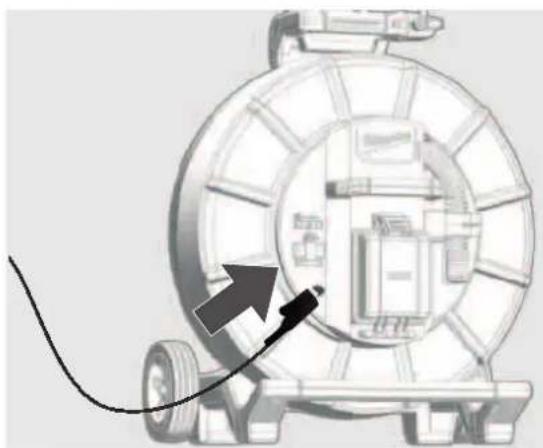
natural_image
Diagram of a mechanical device with a cable and directional arrow, no visible text or symbols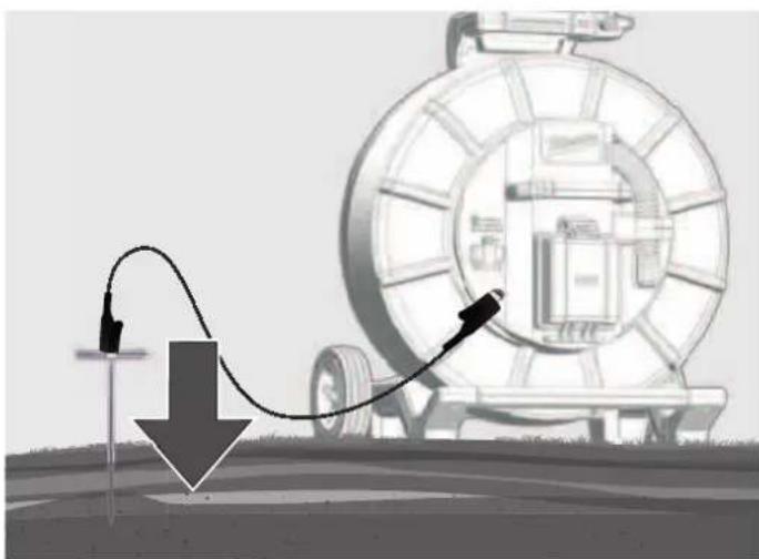
natural_image
Illustration of a pipeline system with a curved pipe and directional arrow, no text or symbols presentnatural_image
Illustration of transmission towers and a cylindrical conductor on a green field, with dashed circular wave patterns around them (no text or symbols)Výkonové signály
natural_image
Three-panel illustration showing a red-handled tool interacting with a mechanical component, displayed in three views (no text or symbols)Cieżar wg procedury EPTA 01/2014 (2,0 ... 6,0 Ah).... 2.56 ... 2.8 kg
natural_image
3D rendered red and green mechanical parts against a gray background (no text or symbols)natural_image
Abstract red wavy line diagram with two vertical dashed circles above it, no text or symbols presentnatural_image
Illustration of a vehicle tire being pulled by a cable, with arrows indicating motion direction (no text or symbols)natural_image
Simple red arrow pointing diagonally upward on a white background with dashed lines (no text or symbols)natural_image
Simple red arrow pointing diagonally upward to the left of a dashed horizontal line (no text or symbols)natural_image
Diagram of a capsule-shaped object with red and green color coding, surrounded by concentric red wave patterns (no text or symbols)natural_image
Black mechanical clamp or bracket component with no visible text or symbols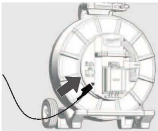
natural_image
Diagram of a mechanical device with a cable and arrow pointing to a component (no text or symbols present)
natural_image
Illustration of a mechanical device with a curved pipe and arrow indicating motion, no text or symbols presentnatural_image
Illustration of transmission towers and a cylindrical conductor on a green field, with dashed circular wave patterns around them (no text or symbols)Sygnały mocy
natural_image
Three-panel diagram showing a red-handled tool interacting with a mechanical component, displayed in three views (no text or symbols)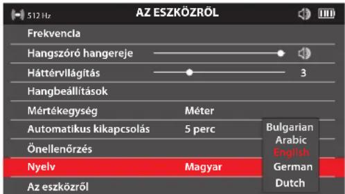
natural_image
3D rendered red and green mechanical parts against a gray background (no text or symbols)natural_image
Abstract red wavy line diagram with two circular markers above it, no text or symbols presentnatural_image
Diagram of a vehicle wheel system with directional arrows indicating motion or force (no text or symbols)natural_image
Simple red arrow symbol pointing diagonally upward on a white background with dashed cross lines (no text or labels)natural_image
Simple red arrow pointing diagonally upward to the left of a dashed coordinate axis (no text or symbols)natural_image
Simple diagram of a capsule-shaped object with red and green segments, surrounded by concentric red wave lines (no text or symbols)natural_image
Black mechanical clamp or bracket component with no visible text or symbols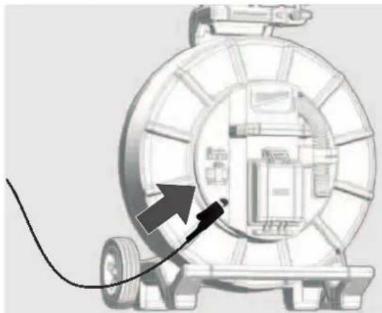
natural_image
Diagram of a mechanical device with a cable and arrow pointing to a component (no text or symbols)
natural_image
Illustration of a pipeline system with a curved pipe and directional arrow, next to a large cylindrical device (no text or symbols)natural_image
Illustration of transmission towers and a cylindrical conductor on a green field, with dashed circular wave patterns around them (no text or symbols)Teljesítményjelek
natural_image
Three-panel illustration showing a red-handled tool with orange handle and black buttons, alongside three views of a mechanical component (no text or symbols)Teža po EPTA-proceduri 01/2014 (2,0 ... 6,0 Ah) ...... 2.56 ... 2.8 kg
- SLOVENSKO
5.
5.5 Frekvenca
V tej točki menija je mogoče nastaviti frekvenco za načine delovanja PASIVNO, AKTIVNO ali SONDA.

natural_image
3D model of a red car with a horizontal bar in the background (no text or symbols)natural_image
Abstract red wavy line diagram with two circular markers above it, no text or symbols presentnatural_image
Illustration of a mechanical device with a large tire and directional arrows indicating motion or flow (no text or symbols)natural_image
Simple red arrow symbol pointing diagonally upward to the left of a dashed coordinate axis (no text or labels)natural_image
Simple red arrow symbol pointing diagonally upward to the left of a dashed coordinate axis (no text or labels)natural_image
Simple diagram of a capsule with red and green color bands, surrounded by concentric red wave lines (no text or symbols)7 DOLOČANJE POLOŽAJA POTISNEGA KABLA IN VODOV
7.1 Pasivno in aktivno določanje položaja
Aktivno Pasivno
natural_image
Black mechanical clamp or bracket component with no visible text or symbols
natural_image
Diagram of a mechanical device with a cable and arrow pointing to a component (no text or symbols)
natural_image
Diagram showing a mechanical device with a curved arrow and downward arrow, no visible text or symbols7.3 Uporaba oddajnega signala
Z BREZŽIČNIM MONITORJEM ali APLIKACIJO ZA PREGLEDOVANJE CEVI podjetja Milwaukee:
– Izberite SLEDENJE KABLA na pritisnite kolesce za krmarjenje.
Na LOKATORJU:
– Izberite frekvenco 33 kHz ali 83 kHz za SLEDENJE KABLA.
| 33kHz | FREKVENCE |
| ((-)) | 512 Hz |
| 640 Hz | |
| 33 kHz | |
| 000 | 33 kHz |
| 83 kHz | |
| 50 Hz | |
| 60 Hz | |
| "A" | RF |
| 83kHz | FREKVENCE |
| (--) | 512 Hz |
| 640 Hz | |
| 33 kHz | |
| 000 | 33 kHz |
| 83 kHz | |
| 50 Hz | |
| 60 Hz | |
| A | RF |
7.4 Stran menija SLEDENJE KABLA
7.5 Sledenje potisnemu kablu
- Vklopite lokator in pritisnite tipko M, da izberete način delovanja SLEDENJE KABLA in frekvenco, ki je nastavljena na BREZŽIČNEM MONITORJU ali v APLIKACIJI ZA PREGLEDOVANJE CEVI.
natural_image
Illustration of transmission towers and a cylindrical antenna on a green field, with dashed circular wave patterns around them (no text or symbols)Močnostni signali
natural_image
Three-panel illustration of a mechanical device with orange and red components, shown from different angles (no text or symbols)Težina po EPTA-proceduri 01/2014 (2,0 ... 6,0 Ah) ...... 2.56 ... 2.8 kg
Bluetooth-pojas frekvencija (pojasevi frekvencija) 2402-2480 MHz
Visokofrekvencijska.... 1,8 dBm
Bluetooth-Verzija 4.0 BT signal mode
Preporučena temperatura okoline kod rada....-18 .... +50 °C
Preporučeni tipovi akumulatora....M12B...
- HIVATSKI
5.
5.5 Frekvencija
Na ovoj stavci izbornika možete postaviti frekvenciju za načine rada PASIVNI, AKTIVNI ili SONDA.
natural_image
3D rendered red and green mechanical parts against a gray background (no text or symbols)Rezultat testa bit će prikazan na zaslonu kao USPJEŠNO ili NEUSPJEŠNO.
5.12 Stranica izbornika INFORMACIJE
natural_image
Abstract red wavy line diagram with two circular markers above it, no text or symbols presentSignal lociranja vrha
natural_image
Illustration of a mechanical device with a large wheel and attached cable, showing motion arrows (no text or symbols)- Gurnite sondu 3 do 4 metra u cijev.
- Idite polako u smjeru strelice.

natural_image
Simple red arrow pointing diagonally upward on a white background with dashed cross lines (no text or symbols)- Krug nulte točke pojavljuje se na zaslonu i prikazuje položaj nultog signala. Približite se toj točki i uzmite je na nišan.

natural_image
Simple red arrow pointing diagonally upward to the left of a dashed horizontal line (no text or symbols)- Nastavite polako u smjeru strelice, dok se ne prikaže simbol sonde. Držite LOKACIJSKI UREĐAJ uspravno i nastavite hodati prema sondi, dok se ne nađe u centru nišana. LOKACIJSKI UREĐAJ sada se nalazi točno iznad sonde.
natural_image
Simple diagram of a capsule-shaped object with red and green color bands, surrounded by concentric red wave lines (no text or symbols)7.1 Pasivno i aktivno lociranje
Aktivno Pasivno
| Definicija | Aktivno lociranje obično se koristi za praćenje i precizno lociranje linija položenih ispod zemlje. Aktivno lociranje uvijek zahtijeva sondu ili odašiljač. | Pasivno lociranje koristi se za pronalaženje nepoznatih podzemnih linija radi njihovog zaobilaženja. Nije prikladno za identifikaciju ili praćenje određenih linija. |
| Načini rada Sonde | Praćenje kabela 33 kHz i 83 kHz | Signali napajanja: 50/60 Hz Radio signali: 15 kHz–27 kHz |
| Izvor SUSTAV ZA PREGLED CIJEVI BEŽIČNI MONITOR APLIKACIJA ZA PROVJERU CIJEVI Sonde | Signali napajanja* – Mreže odašiljača i distribucijske mreže Radio signali* – (LF) predajnici visokonaponske i niske frekvencije. | |
| Područje primjene | Praćenje, identifikacija i precizna lokalizacija podzemno postavljenih linija. Kada je potrebno mjerenje dubine. | Traženje nepoznatih podzemnih vodova kada se ne može koristiti prijenosni signal. Mali, lokalni radovi iskopavanja (npr. postavljanje stupa za ogradu ili prometnog znaka). Posljednja provjera prije iskopavanja. |
natural_image
Black mechanical clamp or bracket component with no visible text or symbols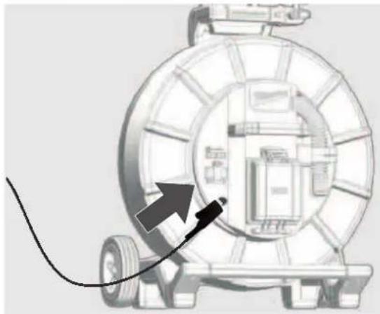
natural_image
Diagram of a mechanical device with a cable and arrow pointing to a component (no text or symbols)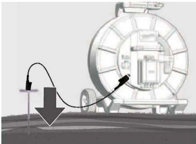
natural_image
Diagram showing a mechanical device with a curved arrow and downward arrow, no visible text or symbols-
Zatim pomoću tipki pretavite osjetljivost na oko 50%.
-
Držite LOKACIJSKI UREĐAJ uspravno i poravnajte ga paralelno s potisnim kabelom. Potom lagano pomjerite udesno. Kad se trakasti grafikon povećava, pomaknite se u smjeru potisnog kabela. Kad se trakasti grafi kon smanjuje, pomaknite se od potisnog kabela.
Pomaknite lokacijski uređaj zdesna ulijevo i obratite pažnju na maksimalni otklon trakastog grafikona.
Kada se nalazite točno iznad potisnog kabela, trakasti grafikon doseže svoj maksimalni otklon (vrh). Prikaz poravnanja postaje plav, dok je smjer potisnog kabela označen bijelim pokazivačem.
natural_image
Illustration of transmission towers and a cylindrical antenna on a green field, with dashed circular wave patterns around them (no text or symbols)Naponski signali
Ovi signali imaju frekvenciju od 50/60 Hz i generiraju se kabelima za napajanje. Ako se električna energija prenosi električnom mrežom, dio energije vraća se u elektranu putem zemlje. Ove zalutale struje mogu se prenijeti na cijevi i kabele, a generiraju i električne signale. Međutim, da bi se generirali mjerljivi signali, mora postojati protok struje. Na primjer, kabel pod naponom, koji se ne koristi, ne emitira mjerljiv signal. Postoji mogućnost da i čak dobro uravnoteženi kabel, kojim teče jednaka količina struje u kabelu pod naponom i u neutralnom vodu, neće generirati signal. Međutim, to se rijetko događa u praksi, zbog čega većina kabela emitira signal koji je lako izmjeriti.
Radio signali
Ove signale generiraju niskofrekventni radio odašiljači poput onih koji se koriste za radio i komunikacijski prijenos. Ako ti signali prelaze dugi vod, poput cijevi ili kabela, signali se reflektiraju natrag. Ovi reflektirani signali prepoznaju se u RF modusu.
8.2 Lociranje naponskih i radio signala
- Uključite LOKACIJSKI UREĐAJ i pritisnite tipku M za odabir načina rada PASIVNO ILI RF.
-
LOKACIJSKI UREĐAJ držite uspravno i što je moguće dalje od kabela ili cjevovoda.
-
Postavite osjetljivost tipkama ▼▲ tako da se trakasti grafikon tek počinje pomicati. Imajte na umu da prikaz poravnanja nije dostupan u načinima rada napajanja ili radio.
NAPOMENA:
Zvučnik ne emitira nikakav zvuk sve dok vrijednost prikaza nije najmanje 10% maksimalnog raspona mjerenja.
Pomaknite lokacijski uređaj zdesna ulijevo i obratite pažnju na maksimalni otklon trakastog grafikona.
natural_image
Three-panel illustration showing a red-handled tool with orange handle and gray base, alongside three zoomed-in views (no text or symbols)- Za dobivanje maksimalnog signala okrenite LOKACIJSKI UREĐAJ oko svoje osi. LOKACIJSKI UREĐAJ sada se nalazi točno iznad linije s osovinom preko linije.
- Poravnanje se također može odrediti okretanjem lokacijskog uređaja dok signal ne bude najslabiji. U ovom slučaju osovina prolazi paralelno s kabelom/cijevi.
- Nastavite locirati liniju dok se ne utvrdi točna ruta u ciljnom području.
9 AŽURIRANJA FIRMVERA
Prije ažuriranja sustava otvorite izbornik POSTAVKE → INFORMACIJE i evidentirajte trenutnu verziju firmvera. Za ažuriranja firmvera koristite našu web lokaciju na https://www.milwaukeetool.eu/.

click
ATC-468-M12PL-SheSera.mdd 1
12.10.2020 18:25:14
SATURS
Svars atbilstoši EPTA -Procedure 01/2014 (2,0 ... 6,0 Ah) ...... 2.56 ... 2.8 kg
Bluetooth frekvenču josla (frekvenču joslas)....2402-2480 MHz
Augustfrekvences.... 1,8 dBm
Bluetooth versija....4.0 BT signal mode
- LATVSKI
5.
5.5 Frekvence


5.6 Skalruņa skalums
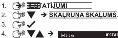
natural_image
3D model of a red and green vehicle with no visible text or symbolsnatural_image
Abstract red wavy line diagram with two circular markers above it, no text or symbols presentnatural_image
Illustration of a tire roller being pulled by a cable, with arrows indicating speed (no text or symbols)natural_image
Simple red arrow pointing diagonally upward to the left of a dashed horizontal line (no text or symbols)natural_image
Simple red arrow pointing diagonally upward to the left of a dashed coordinate grid (no text or symbols)natural_image
Simple diagram of a capsule with red and green color bands, no text or symbols presentnatural_image
Close-up of a black plastic clamp or bracket device with no visible text or symbols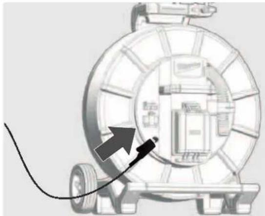
natural_image
Diagram of a mechanical device with a cable and arrow pointing to a component (no text or symbols)
natural_image
Illustration of a mechanical device with a curved pipe and arrow indicating motion, no text or symbols presentnatural_image
Illustration of transmission towers and a cylindrical conductor on a green field, with dashed circular wave patterns around them (no text or symbols)Jaudas signāli
natural_image
Three-panel diagram showing mechanical components with no visible text, numbers, or symbols.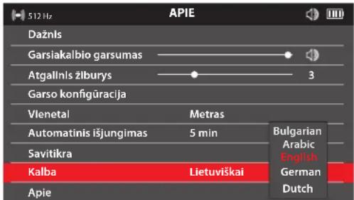
- LIVTIVIŠKA
5.
5.5 Dažnis


5.6 Garsiakalbio garsumas
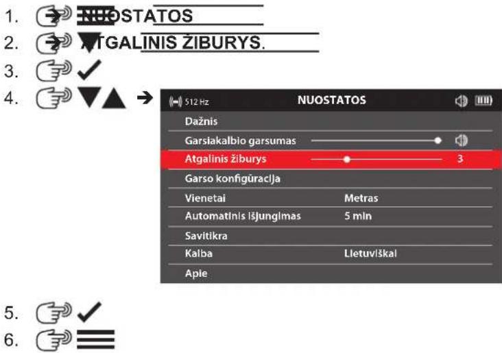
5.7 Atgalinis žiburys
natural_image
3D model of a red and green robotic arm against a gray background (no text or symbols)Ekrane rodomas patikrinimo rezultatas: PAVYKO arba NEPAVYKO.
5.12 Meniu puslapis APIE
natural_image
Abstract red wavy line diagram with two circular markers above it, no text or symbols presentnatural_image
Illustration of a tire roller being pulled by a cable, with arrows indicating motion direction (no text or symbols)- Istumkite zonda 3–4 m j vamzdj.
- Lëtai eikite rodyklës kryptimi.
natural_image
Simple red arrow symbol pointing diagonally upward to the left of a dashed horizontal line (no text or labels)natural_image
Simple red arrow pointing diagonally upward to the left of a dashed horizontal line (no text or symbols)- Toliau létai eikite rodyklés kryptimi, kol ekrane pasirodys zondo simbolis.
natural_image
Simple diagram of a capsule-shaped object with red and green color bands, surrounded by concentric red arcs and dashed centerlines (no text or symbols)7 STUMIAMOJO KABELIO IR LINIJOS VIETOS NUSTATYMAS
natural_image
Black mechanical clamp or bracket component with no visible text or symbols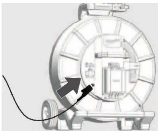
natural_image
Diagram of a mechanical device with a cable and arrow pointing to a circular component (no text or symbols)
natural_image
Illustration of a pipeline system with a cable and directional arrow, no text or symbols presentnatural_image
Illustration of transmission towers and a cylindrical antenna on a green field, with dashed circular wave patterns around them (no text or symbols)Galios signalai
natural_image
Three-panel illustration showing a red-handled tool with orange handle and black buttons, alongside three views of a mechanical component (no text or symbols)1 Üldised juhised....2

4.
5.
5.5 Sagedus

natural_image
3D model of a red and green object with no visible text or symbolsnatural_image
Abstract red wavy line diagram with two circular markers above it, no text or symbols presentnatural_image
Illustration of a mechanical device with a large tire and cable, showing motion arrows (no text or symbols)natural_image
Simple red arrow symbol pointing diagonally upward to the left, intersected by dashed lines (no text or labels)natural_image
Simple red arrow symbol pointing diagonally upward to the left of a dashed coordinate axis (no text or labels)natural_image
Simple diagram of a capsule-shaped object with red and green segments, surrounded by concentric red wave lines (no text or symbols)natural_image
Black mechanical clamp device with multiple arms and mounting holes (no visible text or symbols)
natural_image
Diagram of a mechanical device with a cable and arrow pointing to a component (no text or symbols)
natural_image
Diagram showing a mechanical device with a curved pipe and directional arrow, no visible text or symbolsnatural_image
Illustration of transmission towers and a cylindrical conductor on a green field, with dashed circular wave patterns around them (no text or symbols)Toitesignaalid
natural_image
Three-panel illustration showing a red-handled tool with orange handle and black buttons, alongside three views of a mechanical component (no text or symbols)

natural_image
3D rendered red and green mechanical parts against a gray background (no text or symbols)natural_image
Abstract red wavy line diagram with two vertical dashed circles above it, no text or symbols present.natural_image
Diagram of a mechanical device with a roller and cable, showing motion direction arrows (no text or symbols)natural_image
Simple red arrow pointing diagonally upward to the left of a dashed coordinate axis (no text or symbols)natural_image
Simple red arrow pointing diagonally upward to the left of a dashed coordinate axis (no text or symbols)natural_image
Simple diagram of a capsule-shaped object with red and green color coding, surrounded by concentric red wave lines (no text or symbols)natural_image
Black mechanical clamp or bracket component with no visible text or symbols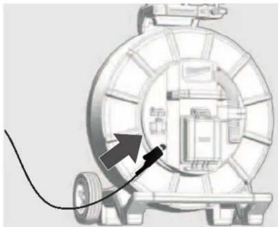
natural_image
Diagram of a mechanical device with a cable and arrow pointing to a component (no text or symbols)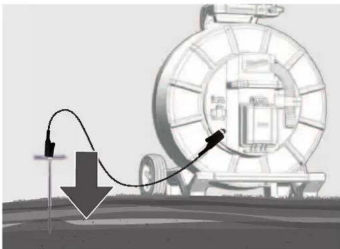
natural_image
Diagram showing a mechanical device with a curved wire and downward arrow, no text or symbols presentnatural_image
Illustration of transmission towers and a cylindrical antenna on a green field, with dashed circular wave patterns around them (no text or symbols)Силовые сигналы
natural_image
Three-panel illustration showing a red-handled tool with orange handle and gray components, arranged in a grid-like structure (no text or symbols)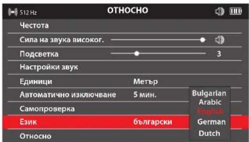
natural_image
3D rendered image of a red mechanical tool next to two horizontal colored bars (red and green) on a gray background, no text or symbols present.natural_image
Abstract red wavy line diagram with two vertical dashed lines and two circular markers above the curve (no text or symbols)natural_image
Illustration of a car tire being pulled by a cable, with arrows indicating motion direction (no text or symbols)natural_image
Simple red arrow symbol pointing diagonally upward to the left, intersected by dashed lines (no text or labels)natural_image
Simple red arrow pointing diagonally upward on a white background with dashed lines (no text or symbols)natural_image
Diagram of a capsule-shaped object with red and green color bands, surrounded by concentric red wave patterns (no text or symbols)natural_image
Black plastic mechanical clamp or bracket component (no visible text or symbols)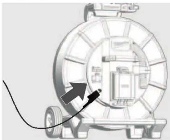
natural_image
Diagram of a mechanical device with a cable and arrow pointing to a component (no text or symbols)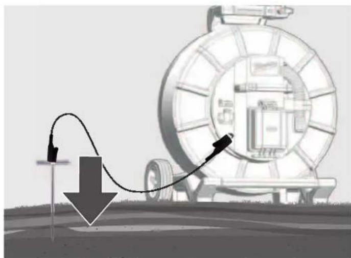
natural_image
Illustration of a mechanical device with a curved cable and directional arrow, no visible text or symbolsnatural_image
Illustration of transmission towers and a cylindrical conductor on a green field, with dashed circular wave patterns around them (no text or symbols)Мощностни сигнали
natural_image
Three-panel diagram showing a red-handled tool interacting with a mechanical component, displayed in three views (no text or symbols)Greutatea conform „EPTA procedure 01/2014" (2,0 ... 6,0 Ah) ...... 2.56 ... 2.8 kg
natural_image
3D model of a red and green object with no visible text or symbolsnatural_image
Abstract red wavy line diagram with two circular markers above it, no text or symbols presentSemnal de localizare peak
natural_image
Illustration of a tire roller being pulled by a cable, with arrows indicating speed (no text or symbols)natural_image
Simple red arrow pointing diagonally upward to the left of a dashed coordinate axis (no text or symbols)natural_image
Simple red arrow pointing diagonally upward to the left of a dashed coordinate grid (no text or symbols)natural_image
Simple diagram of a capsule-shaped object with red and green segments, surrounded by concentric red wave patterns (no text or symbols)7 LOCALIZAREA CABLULUI DE ÎMPINGERE ŞI A CONDUCTEI
natural_image
Close-up of a black mechanical clamp or bracket component (no visible text or symbols)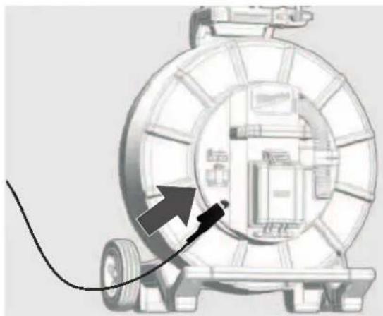
natural_image
Diagram of a mechanical device with a cable and arrow pointing to a component (no text or symbols)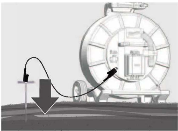
natural_image
Illustration of a pipeline system with a curved pipe passing through a circular tank, showing a downward arrow and control points (no text or symbols)natural_image
Illustration of transmission towers and a cylindrical conductor on a green field, with dashed circular wave patterns around them (no text or symbols)Semnale de putere
natural_image
Three-panel diagram showing a red-handled tool interacting with a mechanical component, displayed in three views (no text or symbols)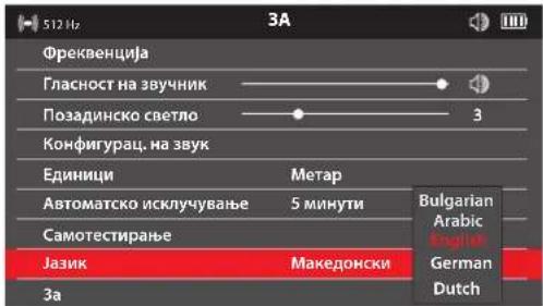
natural_image
3D rendered red and green mechanical tool against gray background (no text or symbols)natural_image
Abstract red wavy line diagram with two circular markers above it, no text or symbols presentnatural_image
Illustration of a mechanical device with a large tire and cable, showing motion arrows (no text or symbols)natural_image
Simple red arrow pointing diagonally upward to the left of a dashed coordinate axis (no text or symbols)natural_image
Simple red arrow pointing diagonally upward on a white background with dashed lines (no text or symbols)natural_image
Simple diagram of a capsule-shaped object with red and green color coding, surrounded by concentric red wave lines (no text or symbols)natural_image
Close-up of a black plastic clamp or bracket component (no visible text or symbols)
natural_image
Diagram of a mechanical device with a cable and directional arrow, no visible text or symbols
natural_image
Illustration of a mechanical device with a curved arrow indicating motion, no text or symbols presentnatural_image
Illustration of transmission towers and a cylindrical conductor on a green field, with dashed circular wave patterns around them (no text or symbols)Струјни сигнали
natural_image
Three-panel illustration showing a red-handled tool interacting with a mechanical component, with no visible text or symbols.natural_image
3D rendered red and green mechanical components on a gray background (no text or symbols)natural_image
Abstract red wavy line diagram with two circular markers above it, no text or symbols presentnatural_image
Illustration of a vehicle tire being pulled by a cable, with arrows indicating motion direction (no text or symbols)natural_image
Simple red arrow symbol pointing diagonally upward to the left, intersected by dashed lines (no text or labels)natural_image
Simple red arrow pointing diagonally upward on a white background with dashed lines (no text or symbols)natural_image
Simple diagram of a capsule with red and green color bands, surrounded by concentric red wave lines (no text or symbols)natural_image
Black mechanical clamp device with multiple arms and mounting holes (no visible text or symbols)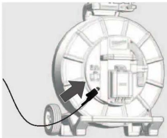
natural_image
Diagram of a mechanical device with a cable and arrow pointing to a component (no text or symbols)
natural_image
Illustration of a pipeline system with a curved pipe passing through a large cylindrical tank, showing flow direction (no text or symbols)natural_image
Illustration of transmission towers and a cylindrical conductor on a green field, with dashed circular wave patterns around them (no text or symbols)Силові сигнали
natural_image
Three-panel illustration showing a red-handled tool with orange handle and black buttons, alongside three views of a mechanical component (no text or symbols)natural_image
Three-panel diagram showing a red-handled tool with orange handle and black body, displayed against a grid background (no text or symbols)natural_image
Illustration of transmission towers and a cylindrical conductor on a green field, with dashed circular wave patterns around them (no text or symbols)إشرات|^ر
natural_image
Black plastic mechanical component with articulated arms and a central handle (no visible text or symbols)
natural_image
Diagram of a mechanical device with a cable and directional arrow, no visible text or symbols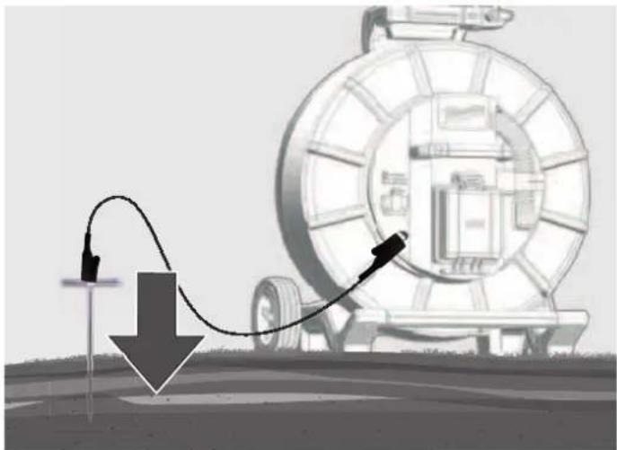
natural_image
Diagram showing a mechanical device with a curved arrow and downward arrow, no text or symbols present7.3 رَة الإرسال
natural_image
Illustration of a mechanical device with a circular component and directional arrows indicating motion or flow (no text or symbols)natural_image
Simple diagram of a capsule-shaped object with red and green segments, surrounded by concentric red wave patterns (no text or symbols)natural_image
Abstract red wavy line diagram with two circular markers above it, no text or symbols present
natural_image
3D rendered red and green robotic arm against gray background (no text or symbols)
5.9 الإوحدات

5.10 الإتلقاني

السید 1
The Ground Truth image displays a single, solid horizontal line. According to Rule 2 (UNDERSCORE & LINE RULES), if the GT contains lines used for stylistic emphasis or as background elements (like ruled paper), the OCR result must ignore them. The provided OCR content is "____", which consists of four underscores. This is incorrect because underscores are not equivalent to a solid line and should not be output for stylistic/background lines. Outputting underscores for background lines violates the rule and constitutes an error. Therefore, the OCR result is inconsistent with the Ground Truth.


تنبيه! ت dhير! خطر!
ONE-KEY. milkwaukeetool.com/one-key