
5378-20 - Drill MILWAUKEE - Free user manual and instructions
Find the device manual for free 5378-20 MILWAUKEE in PDF.


| Product type | Corded drill/driver |
| Brand | Milwaukee |
| Model | 5378-20 |
| Power source | Corded electric, 120 V, 8 A |
| No-load speed | 0-850 rpm (variable) |
| Chuck | 1/2 in (13 mm) keyless |
| Drilling capacity (steel) | 13 mm (1/2 in) |
| Drilling capacity (wood) | 38 mm (1-1/2 in) |
| Reverse rotation switch | Yes |
| Auxiliary handle | Yes, removable |
| Weight | 2.3 kg (5.1 lb) |
| Dimensions (L x W x H) | 28 x 7.5 x 20 cm |
| Cable length | 2.4 m |
| Main functions | Drilling, screwing, unscrewing |
| Maintenance and cleaning | Unplug before cleaning. Clean the body with a damp cloth. Do not use solvents. |
| Safety | Wear safety glasses and gloves. Do not use in wet environments. |
| Spare parts and repairability | Brushes, chuck, switch available through authorized service center. |
| General information | Robust professional drill for heavy-duty work. |
Frequently Asked Questions - 5378-20 MILWAUKEE
User questions about 5378-20 MILWAUKEE
0 question about this device. Answer the ones you know or ask your own.
Ask a new question about this device
Download the instructions for your Drill in PDF format for free! Find your manual 5378-20 - MILWAUKEE and take your electronic device back in hand. On this page are published all the documents necessary for the use of your device. 5378-20 by MILWAUKEE.
USER MANUAL 5378-20 MILWAUKEE
Failure to follow all instructions listed below may result in electric shock, fire and/or serious injury. The term "power tool" in all of the warnings listed below refers to your malns-operated (corded) power tool or battery-operated (cordless) power tool.
SAVE THESE INSTRUCTIONS
WORK AREA SAFETY
- Keep work area clean and well lit. Cluttered or dark areas invite accidents.
- Do not operate power tools in explosive atmospheres, such as in the presence of ammable liquids, gases, or dust. Power tools create sparks which may ignite the dust or fumes.
- Keep children and bystanders away while operating a power tool. Distractions can cause you to lose control.
ELECTRICAL SAFETY
- Power tool plugs must match the outlet. Never modify the plug in any way. Do not use any adapter plugs with earthed (grounded) power tools. Unmodified plugs and matching outlets will reduce risk of electric shock.
- Avoid body contact with earthed or grounded surfaces such as pipes, radiators, ranges and refrigerators. There is an increased risk of electric shock if your body is earthed or grounded.
- Do not expose power tools to rain or wet conditions. Water entering a power tool will increase the risk of electric shock.
- Do not abuse the cord. Never use the cord for carrying, pulling, or unplugging the power tool. Keep cord away from heat, oil, sharp edges, or moving parts. Damaged or entangled cords increase the risk of electric shock.
- When operating a power tool outdoors, use an extension cord suitable for outdoor use. Use of a cord suitable for outdoor use reduces the risk of electric shock.
PERSONAL SAFETY
- Stay alert, watch what you are doing and use common sense when operating a power tool. Do not use a power tool while you are tired or under the influence of drugs, alcohol or medication. A moment of inattention while operating power tools may result in serious personal injury.
- Use safety equipment. Always wear eye protection. Safety equipment such as dust mask, non-skid safety shoes, hard hat, or hearing protection used for appropriate conditions will reduce personal injuries.
- Avoid accidental starting. Ensure the switch is in the off-position before plugging in. Carrying tools with your finger on the switch or plugging in power tools that have the switch on invites accidents.
- Remove any adjusting key or wrench before turning the power tool on. A wrench or a key left attached to a rotating part of the power tool may result in personal injury.
- Do not overreach. Keep proper footing and balance at all times. This enables better control of the power tool in unexpected situations.
- Dress properly. Do not wear loose clothing or jewellery. Keep your hair, clothing and gloves away from moving parts. Loose clothes, jewellery, or long hair can be caught in moving parts.
- If devices are provided for the connection of dust extraction and collection facilities, ensure these are connected and properly used. Use of these devices can reduce dust-related hazards.
POWER TOOL USE AND CARE
- Do not force the power tool. Use the correct power tool for your application. The correct power tool will do the job better and safer at the rate for which it was designed.
- Do not use the power tool if the switch does not turn it on and off. Any power tool that cannot be controlled with the switch is dangerous and must be repaired.
- Disconnect the plug from the power source and/or the battery pack from the power tool before making any adjustments, changing accessories, or storing power tools. Such preventive safety measures reduce the risk of starting the tool accidentally.
- Store idle power tools out of the reach of children and do not allow persons unfamiliar with the power tools or these instructions to operate power tools. Power tools are dangerous in the hands of untrained users.
- Maintain power tools. Check for misalignment or binding of moving parts, breakage of parts and any other condition that may affect the power tool's operation. If damaged, have the power tool repaired before use. Many accidents are caused by poorly maintained power tools.
- Keep cutting tools sharp and clean. Properly maintained cutting tools with sharp cutting edges are less likely to bind and are easier to control.
- Use the power tool, accessories and tool bits etc., in accordance with these instructions and in the manner intended for the particular type of power tool, taking into account the working conditions and the work to be performed. Use of the power tool for operations different from those intended could result in a hazardous situation.
SERVICE
- Have your power tool serviced by a qualified repair person using only identical replacement parts. This will ensure that the safety of the power tool is maintained.
SPECIFIC SAFETY RULES
- Hold tool by insulated gripping surfaces when performing an operation where the cutting tool may contact hidden wiring or its own cord. Contact with a "live" wire will make exposed metal parts of the tool "live" and shock the operator.
- Wear ear protectors when using the tool for extended periods. Prolonged exposure to high intensity noise can cause hearing loss.
- Keep hands away from all cutting edges and moving parts.
- Maintain labels and nameplates. These carry important information. If unreadable or missing, contact a MILWAUKEE service facility for a free replacement.
- WARNING! Some dust created by power sanding, sawing, grinding, drilling, and other construction activities contains chemicals known to cause cancer, birth defects or other reproductive harm. Some examples of these chemicals are:
• lead from lead-based paint
• crystalline silica from bricks and cement and other masonry products, and
• arsenic and chromium from chemically-treated lumber.
Your risk from these exposures varies, depending on how often you do this type of work. To reduce your exposure to these chemicals: work in a well-ventilated area, and work with approved safety equipment, such as those dust masks that are specially designed to filter out microscopic particles.
FUNCTIONAL DESCRIPTION
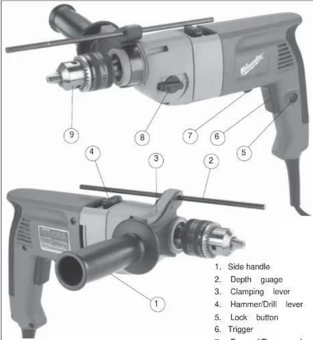
Specifications
| Capacities | ||||||
| Tool | Drill Only(steel or wood) | Rotary Hammer(concrete) | ||||
| Cat.No. | VoltsAC | A | No LoadRPM | No LoadBlows perMinute | TwistDrillBit | Carbide TippedPercussionBit |
| 5378-20and5378-21 | 120 | 7.5 | Low 0 - 1350High 0 - 2500 | 22,00040,000 | 1/2" - 1-1/2" | 5/8" |
GROUNDING

WARNING
Improperly connecting the grounding wire can result in the risk of electric shock. Check with a qualin ed electrician if you are in doubt as to whether the outlet is properly grounded. Do not modify the plug provided with the tool. Never remove the grounding prong from the plug. Do not use the tool if the cord or plug is damaged. If damaged, have it repaired by a MILWAUKEE service facility before use. If the plug will not at the outlet, have a proper outlet installed by a qualin ed electrician.
Grounded Tools:
Tools with Three Prong Plugs
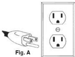
Tools marked "Grounding Required" have a three wire cord and three prong grounding plug. The plug must be connected to a properly grounded outlet (See Figure A). If the tool should electrically malfunction or break down, grounding provides a low resistance path to carry electricity away from the user, reducing the risk of electric shock.
The grounding prong in the plug is connected through the green wire inside the cord to the grounding system in the tool. The green wire in the cord must be the only wire connected to the tool's grounding system and must never be attached to an electrically "live" terminal.
Your tool must be plugged into an appropriate outlet, properly installed and grounded in accordance with all codes and ordinances. The plug and outlet should look like those in Figure A.
Double Insulated Tools:
Tools with Two Prong Plugs
Tools marked "Double Insulated" do not require grounding. They have a special double insulation system which satisfies OSHA requirements and complies with the applicable standards of Underwriters Laboratories, Inc., the Canadian Standard Association and the National Electrical Code. Double Insulated tools may be used in either of the 120 volt outlets shown in Figures B and C.
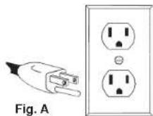
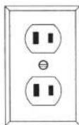
Fig. B

Fig. C
Symbology
| Double Insulated | BPM | Blows per Minute (BPM) | |
| Underwriters Laboratories, Inc. | V~ | Volts Alternating Current | |
| Amps | n_0 × x × x ^-1 | No Load Revolutions per Minute (RPM) | |
| Canadian Standards Association | NOMANCE | Mexican Approvals Marking |
EXTENSION CORDS
Grounded tools require a three wire extension cord. Double insulated tools can use either a two or three wire extension cord. As the distance from the supply outlet increases, you must use a heavier gauge extension cord. Using extension cords with inadequately sized wire causes a serious drop in voltage, resulting in loss of power and possible tool damage. Refer to the table shown to determine the required minimum wire size.
The smaller the gauge number of the wire, the greater the capacity of the cord. For example, a 14 gauge cord can carry a higher current than a 16 gauge cord. When using more than one extension cord to make up the total length, be sure each cord contains at least the minimum wire size required. If you are using one extension cord for more than one tool, add the nameplate amperes and use the sum to determine the required minimum wire size.
Guidelines for Using Extension Cords
- If you are using an extension cord outdoors, be sure it is marked with the suffix "W-A" ("W" in Canada) to indicate that it is acceptable for outdoor use.
- Be sure your extension cord is properly wired and in good electrical condition. Always replace a damaged extension cord or have it repaired by a qualified person before using it.
- Protect your extension cords from sharp objects, excessive heat and damp or wet areas.
Recommended Minimum Wire Gauge for Extension Cords*
| Nameplate Amperes | Extension Cord Length | ||||
| 25' | 50' | 75' | 100' | 150' | |
| 0 - 2.0 | 18 | 18 | 18 | 18 | 16 |
| 2.1 - 3.4 | 18 | 18 | 18 | 16 | 14 |
| 3.5 - 5.0 | 18 | 18 | 16 | 14 | 12 |
| 5.1 - 7.0 | 18 | 16 | 14 | 12 | 12 |
| 7.1 - 12.0 | 16 | 14 | 12 | 10 | |
| 12.1 - 16.0 | 14 | 12 | 10 | ||
| 16.1 - 20.0 | 12 | 10 | |||
* Based on limiting the line voltage drop to five volts at 150% of the rated amperes.
READ AND SAVE ALL INSTRUCTIONS FOR FUTURE USE.
TOOL ASSEMBLY

WARNING
To reduce the risk of injury, always unplug tool before attaching or removing accessories or making adjustments. Use only specifically recommended accessories. Others may be hazardous.
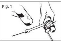
Removing the Chuck (Fig. 1)
natural_image
Illustration of hands using a screwdriver to adjust a screw (no text or symbols present)- Open the chuck jaws fully.
- Remove the screw inside the chuck head. This is a left hand screw, turn clockwise to remove.
- Hold the spindle with a wrench (Fig. 1).
- Insert the drill chuck key inside chuck and loosen clockwise by tapping lightly with a rubber hammer.
NOTE: To mount the chuck, reverse the instructions above.

WARNING
To prevent personal injury, always remove the chuck key from the chuck after each use.
Installing Bits into Keyed Chucks (Fig. 2)
Be sure that the shank of the bit and the chuck jaws are clean. Dirt particles may cause the bit to line up improperly. Do not use bits larger than the maximum recommended capacity of the drill because gear damage or motor overloading may result. For best performance, be sure that the bits are properly sharpened before use.

- Unplug the tool.
- Open the chuck jaws wide enough to insert a bit. Allow the bit to strike the bottom of the chuck. Center the bit in the chuck jaws and tighten the jaws by hand to align the bit.
- Place the chuck key into each of the three holes in the chuck, turning it clockwise to tighten the chuck securely. NOTE: Never use a wrench or means other than a chuck key to tighten or loosen the chuck.
- To remove the bit, insert the chuck key into one of the holes in the chuck and turn it counterclockwise.

WARNING
To reduce the risk of injury, always use a side handle when using this tool. Always brace or hold securely.
Adjusting the Side Handle Position (Fig. 3)

- Loosen the side handle by unscrewing the side handle grip until the side handle rotates freely.
- Rotate the side handle to the desired position.
- Tighten the side handle grip securely.
Setting the Depth Gauge (Fig. 4)

- Press in the clamping lever.
- Slide the depth gauge rod backward or forward until it is set for the desired depth.
NOTE: The drilling depth is the distance between the tip of the bit and the tip of the depth gauge rod. - Release the clamping lever.
OPERATION

WARNING
To reduce the risk of injury, wear safety goggles or glasses with side shields. Unplug the tool before changing accessories or making adjustments.
Selecting Action (Fig. 5)
MILWAUKEE Hammer-Drills have two settings: drilling and hammer-drilling.
Fig. 5
Selector Lever

natural_image
Close-up of a mechanical tool with a drill bit and shaft (no visible text or symbols)- For drilling, turn the hammer-drill lever towards the drill symbol.
- For hammer-drilling, turn the hammer-drill lever towards the hammer symbol ☐.
NOTE: To engage the hammering mechanism, maintain pressure on the bit. When pressure on the bit is released, the hammering action will stop.
Using Forward/Reverse Lever (Fig. 6)
The forward/reverse lever can only be adjusted when the trigger is not pressed. Always allow the motor to come to a complete stop before using the forward/reverse lever.
Fig. 6
Forward

- For forward (clockwise) rotation, push the forward/reverse lever to the left (when viewed from the back of the tool) as shown.
- For reverse (counterclockwise) rotation, push the forward/reverse lever to the right (when viewed from the back of the tool) as shown. Allow the motor to come to a full stop before reversing.
NOTE: When hammer-drilling, use the tool in forward rotation (clockwise) only.
Selecting Speed
The speed can be changed when the tool is at a complete stop or running under no load.
- For low speed (up to 1350 rpm), turn the speed selector to position 1.
- For high speed (up to 2500 rpm), turn the speed selector to position 2.
Starting, Stopping & Controlling Speed
- To start the tool, pull trigger.
- To stop the tool, release trigger.
- To vary the speed, increase or decrease pressure to trigger. The further the trigger is pulled, the greater the speed.
Operating
Position the tool, grasp the handles firmly and pull the trigger. Always hold the tool securely using both handles and maintain control. This tool has been designed to achieve top performance with only moderate pressure. Let the tool do the work.
If the speed begins to drop off when drilling deep holes, pull the bit partially out of the hole while the tool is running to help clear dust. Do not use water to settle the dust since it will clog the bit utes and tend to make the bit bind in the hole.
APPLICATIONS

WARNING
To reduce the risk of electric shock, check work area for hidden pipes and wires before drilling.
Drilling in Wood, Composition Materials and Plastic
When drilling in wood, composition materials and plastic, select the drill operating mode. Start the drill slowly, gradually increasing speed as you drill. Select low speeds for plastics with a low melting point.
Drilling in Metal
When drilling in metal, select the drill operating mode. Use high speed steel twist drills or hole saws. Use a center punch to start the hole. Lubricate drill bits with cutting oil when drilling in iron or steel. Use a coolant when drilling in nonferrous metals such as copper, brass or aluminum. Back the material to prevent binding and distortion on breakthrough.
Drilling in Masonry
When drilling in masonry, select the hammer-drill operating mode. Use high speed carbide-tipped bits. Drilling soft masonry materials such as cinder block requires little pressure. Hard materials like concrete require more pressure. A smooth, even low of dust indicates the proper drilling rate. Do not let the bit spin in the hole without cutting. Do not use water to settle dust or to cool bit. Do not attempt to drill through steel reinforcing rods. Both actions will damage the carbide.
MAINTENANCE

WARNING
To reduce the risk of injury, always unplug your tool before performing any maintenance. Never disassemble the tool or try to do any rewiring on the tool's electrical system. Contact a MILWAUKEE service facility for ALL repairs.
Maintaining Tools
Keep your tool in good repair by adopting a regular maintenance program. Before use, examine the general condition of your tool. Inspect guards, switches, tool cord set and extension cord for damage. Check for loose screws, misalignment, binding of moving parts, improper mounting, broken parts and any other condition that may affect its safe operation. If abnormal noise or vibration occurs, turn the tool off immediately and have the problem corrected before further use. Do not use a damaged tool. Tag damaged tools "DO NOT USE" until repaired (see "Repairs").
Under normal conditions, relubrication is not necessary until the motor brushes need to be replaced. After six months to one year, depending on use, return your tool to the nearest MILWAUKEE service facility for the following:
- Lubrication
• Brush inspection and replacement - Mechanical inspection and cleaning (gears, spindles, bearings, housing, etc.)
• Electrical inspection (switch, cord, armature, etc.)
• Testing to assure proper mechanical and electrical operation

WARNING
To reduce the risk of Injury, electric shock and damage to the tool, never immerse your tool in liquid or allow a liquid to 1 ow inside the tool.
Cleaning
Clean dust and debris from vents. Keep the tool handles clean, dry and free of oil or grease. Use only mild soap and a damp cloth to clean your tool since certain cleaning agents and solvents are harmful to plastics and other insulated parts. Some of these include: gasoline, turpentine, lacquer thinner, paint thinner, chlorinated cleaning solvents, ammonia and household detergents containing ammonia. Never use ammable or combustible solvents around tools.
Repairs
If your tool is damaged, return the entire tool to the nearest service center.
ACCESSORIES

WARNING
To reduce the risk of injury, always unplug the tool before attaching or removing accessories. Use only speci cally recommended accessories. Others may be hazardous.
For a complete listing of accessories refer to your MILWAUKEE Electric Tool catalog or go on-line to www.milwaukeetool.com. To obtain a catalog, contact your local distributor or a service center.
Side Handle
Cat. No. 49-15-5300
FIVE YEAR TOOL LIMITED WARRANTY
Every MILWAUKEE tool is tested before leaving the factory and is warranted to be free from defects in material and workmanship. MILWAUKEE will repair or replace (at MILWAUKEE's discretion), without charge, any tool (including battery chargers) which examination proves to be defective in material or workmanship from li ve (5) years after the date of purchase. Return the tool and a copy of the purchase receipt or other proof of purchase to a MILWAUKEE Factory Service/Sales Support Branch location or MILWAUKEE Authorized Service Station, freight prepaid and insured. This warranty does not cover damage from repairs made or attempted by other than MILWAUKEE authorized personnel, abuse, normal wear and tear, lack of maintenance, or accidents.
The warranty period for V28 Battery Packs is two (2) years from the date of purchase. The warranty period for Ni-Cd battery Packs, Flashlights, Radios are warranted for one (1) year from the date of purchase.
THE REPAIR AND REPLACEMENT REMEDIES DESCRIBED HEREIN ARE EXCLUSIVE. IN NO EVENT SHALL MILWAUKEE BE LIABLE FOR ANY INCIDENTAL, SPECIAL, OR CONSEQUENTIAL DAMAGES, INCLUDING LOSS OF PROFITS.
THIS WARRANTY IS EXCLUSIVE AND IN LIEU OF ALL OTHER WARRANTIES, OR CONDITIONS, WRITTEN OR ORAL, EXPRESSED OR IMPLIED FOR MERCHANTABILITY OR FITNESS FOR PARTICULAR USE OR PURPOSE.
This warranty gives you specific legal rights. You may also have other rights that vary from state to state and province to province. In those states that do not allow the exclusion of implied warranties or limitation of incidental or consequential damages, the above limitations or exclusions may not apply to you. This warranty applies to the United States, Canada, and Mexico only.
RÈGLES GÉNÉRALES DE SÉCURITÉ POUR LES OUTILS ÉLECTRIQUE

AVERTISSEMENT
LIRE SOIGNEUSEMENT TOUTES LES INSTRUCTIONS
natural_image
Illustration of hands using a wrench to adjust a screwdriver (no text or symbols present)natural_image
Close-up of a mechanical tool with a drill bit and shaft (no visible text or symbols)natural_image
Two identical electrical socket diagrams with internal circuit breakers, no text or symbols presentFig. B
natural_image
Electrical plug and socket diagram showing two socket layouts (no text or symbols)Fig. C
EXTENSIONES ELECTRICAS
natural_image
Illustration of hands using a wrench to adjust a mechanical component (no text or symbols present)UNITED STATES - MILWAUKEE Service
MILWAUKEE prides itself in producing a premium quality product that is NOTHING BUT HEAVY DUTY ^® . Your satisfaction with our products is very important to us! If you encounter any problems with the operation of this tool, or you would like to locate the factory Service/Sales Support Branch or authorized service station
nearest you, please call.
1-800-SAWDUST
(1.800.729.3878)
NATIONWIDE TOLL FREE
Monday-Friday • 8:00 AM - 4:30 PM • Central Time
or visit our website at
www.milwaukeetool.com
For service information, use the 'Service Center Search' icon found in the 'Parts & Service' section. Additionally, we have a nationwide network of authorized Distributors ready to assist you with your tool and accessory needs. Check your "Yellow Pages" phone directory under "Tools-Electric" for the names & addresses of those nearest you or see the 'Where To Buy' section of our website.
Corporate After Sales Service - Technical Support
Brookfield, Wisconsin USA
•Technical Questions •Service/Repair Questions •Warranty
1-800-SAWDUST
(1.800.729.3878) fax: 1.800.638.9582
email: metproductsupport@milwaukeeetool.com
Monday-Friday • 8:00 AM - 4:30 PM • Central Time
Canada - Service MILWAUKEE
Milwaukee Electric Tool (Canada) Ltd
755 Progress Avenue
Scarborough, Ontario M1H 2W7
Milwaukee Electric Tool, S.A. de C.V.
Blvd. Abraham Lincoln no. 13
Colonia Los Reyes Zona Industrial
Hainepantla, Edo. Mexico C.P. 54073
Tel. (55) 5565-1414 Fax: (55) 5565-6874
MILWAUKEE ELECTRIC TOOL CORPORATION
13135 West Lisbon Road • Brookeld, Wisconsin, U.S.A. 53005
58-14-5378d11
10/05
Printed in USA


- SAVE THESE INSTRUCTIONS
- WORK AREA SAFETY
- ELECTRICAL SAFETY
- PERSONAL SAFETY
- POWER TOOL USE AND CARE
- SERVICE
- SPECIFIC SAFETY RULES
- GROUNDING
- WARNING
- Grounded Tools:
- Tools with Three Prong Plugs
- Double Insulated Tools:
- Tools with Two Prong Plugs
- EXTENSION CORDS
- Guidelines for Using Extension Cords
- READ AND SAVE ALL INSTRUCTIONS FOR FUTURE USE.
- TOOL ASSEMBLY
- Installing Bits into Keyed Chucks (Fig. 2)
- OPERATION
- Selecting Action (Fig. 5)
- Using Forward/Reverse Lever (Fig. 6)
- Selecting Speed
- Starting, Stopping & Controlling Speed
- Operating
- APPLICATIONS
- Drilling in Wood, Composition Materials and Plastic
- Drilling in Metal
- Drilling in Masonry
- MAINTENANCE
- Maintaining Tools
- Cleaning
- Repairs
- ACCESSORIES
- Side Handle
- FIVE YEAR TOOL LIMITED WARRANTY
- RÈGLES GÉNÉRALES DE SÉCURITÉ POUR LES OUTILS ÉLECTRIQUE
- AVERTISSEMENT
- LIRE SOIGNEUSEMENT TOUTES LES INSTRUCTIONS
- EXTENSIONES ELECTRICAS
- UNITED STATES - MILWAUKEE Service
- 1-800-SAWDUST
- www.milwaukeetool.com
- Canada - Service MILWAUKEE
- Milwaukee Electric Tool (Canada) Ltd
- MILWAUKEE ELECTRIC TOOL CORPORATION
Brand : MILWAUKEE
Model : 5378-20
Category : Drill