
VMD 2.5 Display - Air conditioner DOMETIC - Free user manual and instructions
Find the device manual for free VMD 2.5 Display DOMETIC in PDF.
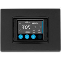


| Product type | Control panel for marine air conditioning |
| Brand | Dometic |
| Model | VMD 2.5 Display |
| Power supply | 12 V DC |
| Dimensions (W x H) | 120 x 65 mm (with bezel) |
| Weight | Approximately 0.2 kg |
| Compatibility | Marine air conditioning systems MV2 series and Dometic control boards |
| Operating modes | Cooling, Heating, Auto, Fan only |
| Special functions | Eco mode, Silent mode, Scheduler (up to 4 programs) |
| Display | Ambient temperature, relative humidity, mode icons, alarms |
| Built-in sensors | Ambient temperature; humidity (optional) |
| Security lock | 4-digit PIN code to protect menus |
| Available languages | Multilingual (including French) |
| Screen type | TFT, adjustable brightness |
| Operating temperature range | 0 °C to 60 °C |
| Installation | Wall mounting, requires screen cable provided with the air conditioner |
| Spare parts available | Screen cable, optional bezel |
| Warranty | 2 years (depending on country) |
Frequently Asked Questions - VMD 2.5 Display DOMETIC
User questions about VMD 2.5 Display DOMETIC
0 question about this device. Answer the ones you know or ask your own.
Ask a new question about this device
Download the instructions for your Air conditioner in PDF format for free! Find your manual VMD 2.5 Display - DOMETIC and take your electronic device back in hand. On this page are published all the documents necessary for the use of your device. VMD 2.5 Display by DOMETIC.
USER MANUAL VMD 2.5 Display DOMETIC
Handling recreational marine vessel parts can expose you to chemicals such as phthalates and lead, which can cause cancer and reproductive harm. To minimize exposure, service the vessel outdoors or in a well-ventilated area, wear gloves, and wash your hands. For more information see www.P65Warnings.ca.gov/marine-vessel-parts.
Display VMD2.5
EN Marine Air Conditioner Display Installation and Operating Manual
The visual appearance of the contents of this manual is protected by copyright and design law. The underlying technical design and the products contained herein may be protected by design, patent, or pending patent. The trademarks mentioned in this manual belong to Dometic Sweden AB. All rights reserved.
English
| 0 | Important notes....T |
| I | RSplanation of symbols....T |
| T | Intended use....T |
| U | *cope of delivery....T |
| K | Nools....T |
| V | Installation....T |
| W | Operation....U |
| X | Troubleshooting....Y |
| Y | Z arranty....QI |
| QJ | L isposal....QI |
| Technical data....QI |
1) Important notes
Please read these instructions carefully and follow all instructions, guidelines, and warnings included in this product manual in order to ensure that you install, use, and maintain the product properly at all times. These instructions must stay with this product.
By using the product, you hereby acknowledge that you have read all instructions, guidelines, and warnings carefully and that you understand and agree to abide by the terms and conditions as set forth herein. You agree to use this product only for the intended purpose and application and in accordance with the instructions, guidelines, and warnings as set forth in this product manual as well as in accordance with all applicable laws and regulations. Failure to read and follow the instructions and warnings set forth herein may result in injury to yourself and others, damage to your product, or damage to other property in the vicinity. This product manual, including the instructions, guidelines, and warnings, and related documentation may be subject to changes and updates. For up-to-date product information, please visit documents.dometic.com.
2 Explanation of symbols
A signal word will identify safety messages and property damage messages; and also will indicate the degree or level of hazard seriousness.

2 WARNING
Indicates a hazardous situation that, if not avoided, could result in death or serious injury.

2 CAUTION
Indicates a situation that, if not avoided, could result in property damage.

2 NOTE Supplementary information for operating the product.
2.1 Supplemental directives
To reduce the risk of accidents and injuries, please observe the following directives before proceeding to install and/or operate this product:
- Read and follow all safety information and instructions.
- Read and understand these instructions before installing or operating this product.
- The installation must comply with all applicable local or national codes, including the latest edition of the following standards:
- American Boat and Yacht Council (ABYC) E-11 and NFPA 70 National Electrical Code
2.2 General safety messages

WARNING: Electrical shock, fire and/or explosion hazard. Failure to obey this warning could result in death or serious injury.
Use only genuine replacement parts and components that are specifically approved for use with the product. Avoid improper installation, adjustment, alterations, service, or maintenance of the product. Service and maintenance must be done by a qualified service person only. Do not modify this product in any way. Modification can be extremely hazardous.
3) Intended Use
The display (hereinafter referred to as display or product) is the control interface for operating compatible marine air conditioning systems. This display is only suitable for the intended purpose and application in accordance with these instructions.
This manual provides information that is necessary for proper installation and/or operation of the display. Poor installation and/or improper operation will result in
unsatisfactory performance and a possible failure. The manufacturer accepts no liability for any injury or damage to the product resulting from:
- Incorrect assembly or connection, including excess voltage.
- Incorrect maintenance or use of spare parts other than original spare parts provided by the manufacturer.
- Alterations to the product without express permission from the manufacturer. Use for purposes other than those described in this manual. Dometic reserves the right to change product appearance and product specifications.
4 Scope of delivery
This section describes the parts included with the display. Optional parts can be purchased separately.
Included parts Quantity
Display 1
M4 x 6 in. self-tapping screws 4
Installation and operation manual 1
Optional parts Quantity
| Bezel | Q |
| L isplay cable | | KJ g cM.VI lm: or KJ J lg cK.I Umd |

The display cable is included with the Mf Nj series marine air conditioner.
5 Tools
Dometic recommends that the following tools be used when installing the display:
- Screwdriver/bit • Drill • Marker
- Sabre saw/multi-tool saw
6) Installation

2 WARNING: Electrical shock, fire, and/or explosion hazard. Failure to obey the following warnings could result in death or serious injury:
Prior to cutting or drilling, disconnect the power supply. Verify that there are no obstacles such as wires or pipes inside the cabin walls at the display mounting location.

WARNING: Damage hazard. Do not locate the display panel in direct sunlight, near any heat-producing appliances, or in a bulkhead where temperatures radiating from behind the panel may affect performance.

WARNING: Damage hazard. Do not use a screw gun and do not overtighten the screws when mounting the display.

WARNING: Damage hazard. Do not staple sensor cables during installation.
6.1 Choosing the display location
The location chosen for the display should meet the following criteria:
- • An inside wall of the cabin, out of direct sunlight
- • Positioned slightly higher than mid-height of the cabin wall • In an area with freely circulating air
- • A maximum distance of 1.5 m from the air conditioner
6.2 Preparing the mounting location
1. Disconnect the power supply. 2. All opening dimensions
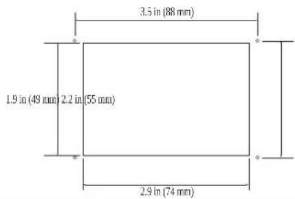
- Mark the dimensions of the opening and the screw hole locations on the cabin wall.
T. Cut out the opening.
U. Drill four screw holes.
6.3) Installing the display
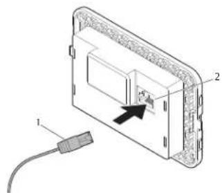
Q. Route one end of the display cable through the electrical control box of the air conditioner and plug it into the jack on the circuit board. Routing the display cable
□
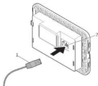
1 Display cable 2 Jack
- Route the other end of the display cable through the wall opening and plug it into the jack on the back of the display.
T. Use the screws to secure the display to the cabin wall.
U. Snap the bezel (optional) onto the display.
a 1 Operation

2 WARNING Electrical shock hazard
Failure to obey this warning could result in death or serious injury. The display remains powered when the power control is off. Disconnect the power supply prior to performing any maintenance on the display.
This system uses variable speed technology which allows the compressor to operate for long periods instead of constantly cycling on and off. The benefits include increased reliability, reduced energy consumption, improved de-humidification, and lower operating noise levels.
a.1 Home screen
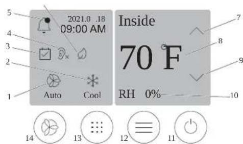
1 | Fan speed indicator a / Temperature / set point indicator
2 Mode indicator b Temperature down control
3 Scheduler indicator c Relative humidity indicator
4 Quiet mode indicator d Power control
| 5 | * larm indicator/control | 12 | Main menu control |
| 6 | Rco mode indicatoro | 13 | Mode control |
| a | Memperature up control | 14 | ]an speed control |
o Only available on MF NJ series
a- le 1e Home screen controls and status indicators
| ) on | Control/indicator | Des ription |
 | Mode indicator | Nhe mode icon shows the current operating mode.Nhe icon is animated when the compressor is running and static when it is not running. Nhe icon clashes when the compressor cycles ol and enters a three-minute delay mode before it can cycle bac on. |
| i N1 &E Nhe icon for cool mode is shown in this eSample. | ||
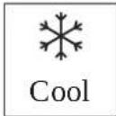 | Mode: bool | Nhe system will run a cooling cycle when the cabin temperature rises above the cooling set point by the set point differential. Nhe default set point differential is l q] d.o qbd, aeler to Parameters on pageV to learn how to adjust the set point differential. Icon will animate when the compressor is operational. |
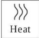 | Mode: r eat | Nhe system will run a heating cycle when the cabin temperature calls below the heating set point by the set point differential. Nhe default set point differential is l q] d.o qbd, aeler to Parameters on pageV to learn how to adjust the set point differential. Icon will animate when the compressor is operational. |
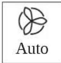
 | Mode: *uto | Nhe system will automatically switch between a cooling and a reverse cheating: cycle depending on whether the cabin temperature goes above or below the set point by U q] d.o qbd. |
 | Mode: ] an only | Nhe system will run the fan to circulate the air continuously turning on the compressor. |
 | ] an speed indicator | Nhe indicator shows the selected fan speed. In modes other than ] an OnlyF the indicator shows " u-toF indicating that the fan speed is following the compressor speed. This is the ideal setting for true variable capacity performance. Nhe icon is animated when the fan is running and static it is not running, aeler to Parameters on pageV to learn how to adjust the low and high fan speeds. Icon will animate when the fan is operating. |
 ) on Control/indi- ) on Control/indi- | *cheduler indicatorator | Nhe indicator appears when a scheduled program is active, aeler to *cheduler mode on pageV to learn how to turn *chedular mode on/ol and set up and run programs.Des ription |
 | ' larm indica-tor/control | Nhis indicator appears when there is an active alarm, clearing the alarm notification does not resolve the alarm. Nhe alarm notification will reappear on the rome screen until the problem is resolved, aeter to Troubleshooting for information on resolving alarms.Nap the "larm indicator to display the current alarm.Ti there are more than two alarms 9 tap the . p 'r-row and L own " rrow to navigate through the "larm list.Nap an alarm from the list to view the details.Nap CLR to clear an individual alarm from the "larm L etails screen. |
| n uiet mode indicatoro | Nhe indicator appears when the function is active, aeter to n uiet mode on page/V to learn how to turn n uiet mode on/oI and adjust the set point. | |
| Rco mode indi-catoro | Nhe indicator appears when the function is active, aeter to Rco mode on page/K to learn how to turn the mode on/oI and adjust the set point. | |
| . p arrow Nap to raise the temperature on the rome screen.On other screens 2 tap to navigate to the earlier menu and/or raise a numerical value. | ||
| 70 F | Tempera-ture/set point indicator | Nhe indicator displays the new temperature set point while the temperature set point is adjusted with the . p ' rrow or L own " row? then displays the tempera-ture in the cabin. |
| L own arrow Nap to lower the temperature on the rome screen.On other screens 2 tap to navigate to the neSt menu and/or lower a numerical value. | ||
| RH 0% | aelative humidi-ty indicator | Nhe indicator displays the relative humidity in the cabin if a humidity sensor is installed. |
| Dower control Nhe power button turns the system on or ol , Z hen onP the system will run in the selected mode when the cabin temperature is higher doool model or low-er or eat model than the set point. Z hen of F the sys-tem will not run although it will stay in communica-tion with the networ cf present.&ap and ' old to toggle t' e po4 er on or o//. | ||
| Main menu con-trol | Nhe Main menu is used to set up 9 schedule 3 and trou-bleshoot the system.Nap to display the [ rst Main menu screen 9 then tap the L own ' rrow to display the second Main Menu screen. | |
| Mode control Nap to cycle through toolP r eatP ' uto 2 and ] an Only. | ||

o Only available on MF NJ series
a- le 2e Additional controls
) on Control/indi-


a.2 Eco mode
No help. Extend running time and limit power usage use Eco mode. When enabled, Eco mode limits the maximum power used by the unit. This results in a reduction in required current and an increase in energy efficiency. By reducing the unit's maximum capacity, the unit can operate when power requirements are limited. This option is only available on variable capacity units.

Note: Eco mode and Quiet mode can be active at the same time. The system will operate at the set point that is the lowest. Be advised that setting the set point too low can affect the system's cooling capability.
a.2.1 Turning Eco mode on or off
- On the home screen, tap Main Menu.
- Tap Function.
Tap Eco Mode to toggle the function on or off.
The Eco Mode indicator will display on the home screen if the mode is on.
a.2.2 Adjusting the Eco Mode set point
On the home screen, tap Main Menu.
- Tap Function.
Tap Eco Mode:
Tap the down arrow.
Tap Eco Mode Set Point.
Tap the left arrow or right arrow to adjust the set point.
Tap Save.
The Eco Mode indicator will display on the home screen if the mode is on.
Users can enable Quiet mode to limit the maximum speed, reducing disturbances during the night. Quiet mode ensures the unit runs consistently until the on/off cycling of traditional air conditioning systems. If the unit is overly restricted in Quiet mode, the unit will bypass this mode to bring the space back to a comfortable temperature. This option is only available on variable capacity units.
Eco mode and Quiet mode can be active at the same time. The system will operate at the set point that is the lowest. Be advised that setting the set point too low can affect the system's cooling capability. Quiet mode will automatically turn off if the temperature is more than 6°F from the set point.
3.1 Turning Quiet mode on or off
- On the Home screen, tap Main Menu.
- Tap Function.
Tap Quiet Mode to toggle the function on or off.
When Quiet Mode is on, the indicator will display on the Home screen.
3.2 Adjusting the Quiet mode set point
To find the best set point, slowly decrease the set point percentage until the desired noise level is reached.
- On the Home screen, tap Main Menu.
- Map Function.
T. Vap Quiet Mode.
U. Map the down arrow.
K. Map Quiet Mode Set Point.
V. Nap the leg arrow or right arrow to adjust the set point.
W Nap Ave.
The Quiet Mode indicator will display on the home screen if the mode is on.
a.4 Scheduler mode
Scheduler mode can automatically run up to four programs once they have been set up and activated. Programs can be set for desired days and times and include modes, functions, and temperatures.
a.4.1 Turning Scheduler mode on or off
Scheduler mode must be turned on to run or edit programs.
- On the home screen, tap Main Menu.
- Map Scheduler.
Tap scheduled to toggle the function on or off.
a.4.2 Enabling or disabling a program
Scheduler mode must be turned on to run programs. Programs and their scheduled actions will be shown on the Program screen.
On the Home screen, tap Main Menu.
- Tap Scheduler.
Tap Programs.
Use the up arrow or down arrow to navigate to the program.
Tap the program menu bar to enable or disable the program.
a.4.3 Editing a program
Program options include setting the mode, functions, temperature set point, and the time and days of the week the program will run once turned on.
- On the Home screen, tap Main Menu.
- Tap Scheduler.
T. Nap Programs.
U. Use the up arrow or down arrow to navigate to the desired program screen.
K. Nap [L] :Rditl.
V. Tap * Lcat do ooldF or eato 0 Xus c" utod or off to select the mode, then tap the down arrow to move to the next screen.
W. Tap Model and/or outlet Mode to turn these functions on or off, then tap the down arrow. These functions will not be available if the mode selected in the earlier step was off. Both can be set to on or off as desired.
X. Tap the left arrow or right arrow to set the temperature, then tap the down arrow.
Y. Tap the left arrow or right arrow to set the time, then tap the down arrow.
3). Tap one or more days to set which days the program will run.
- Map □ saved to save the program.
a.5 Parameters
- From the home screen, tap ⓄMain Menu.
- Tap Parameters, then use the up arrow and down arrow to scroll through the selections.
| Sele tion Des ription A tions | ||
| Memorize Setting | Nhis selection memorizes the current set- tings for all parameters providing a sys- tem-wide point that can be returned to when troubleshooting. | Q. Nap Memorize Set- tings.1. Nap Yes.T.Nap cO/d. |
| Recall Memo- rized | Nhis selection returns all parameters to the last memorized settings. | Q. Nap Recall Memo- rize.1. Nap Yes.T.Nap cO/d. |
| Recall De- faults | Nhis selection returns all parameters to their factory settings. | Q. Nap Recall Facto- ry.1. Nap Yes.T.Nap cO/d. |
| High Fan Speed | Nhis selection adjusts the fan speed on the high setting reducing the air noise pro- duced by the system. | Q. Nap High Fan Speed.1. Nap the leg arrow or right arrow to adjust the maSi- mum fan speed percent- age.T.Napave. |
| Low Fan Speed | Nhis selection adjusts the fan speed on the low setting ensuring the fan speed is high enough to overcome the static pressure in ductwor . | Q. Nap Low Fan Speed.1. Nap the leg arrow or right arrow to adjust the mini- mum fan speed percent- age.T.Napave. |
| Fan Operate Mode | *electing Continuous eeps the fan running at slow speed when the compres- sor cycles ol. *electing Cycled turns the fan ol and on with the compressor. | Q. Nap Fan Operate Mode.1. Nap Continuous or Cycled. |
| Pump Operate Mode | *electing Continuous eeps the pump running continuously when the compressor cycles ol. *electing Cycled turns the pump ol and on with the compressor. | Q. Nap Pump Operate Mode.I. Nap Continuous or Cycled |
| Room Temp Offset | Nhis selection is used to calibrate the cab-in temperature reading when it is consistently different from the actual tempera-ture. | Q. Nap Inside Temp Calibrate.I. Nap the leg arrow or right arrow to adjust the read-ing.T.Nap Paved. |
| Temperature Units | Nhis selection toggles temperature read-outs between cl and qb and alects all temperature screens. Nhe default is ql. | Nap Temperature Units to toggle between ql or qb. |
| Pressure Units | Nhis selection toggles pressure readouts between psi2 /pa3 or bar and alects all pressure screens. Nhe default is psi. | Q. Nap Pressure Units.I. Nap the leg arrow or right arrow to adjust the read-ing.T.Nap Paved. |
| Aux Electric Heat | Nhis selection activates the auxiliary elec-tric heater relay is one is connected. " uS Electric r eat will only wor in place of the reverse heating cycle and not as a supple-mentary heat source. Nhe default is ol. Nhe appropriate power rating must be se-lected to activate the heater. | Q. Nap Aux Electric Heat.I. Nap the leg arrow or right arrow to scroll through the options.T.Nap Paved and Col-low the prompts to con-firm the selection. |
| Filter Hours Setting | Z hen activated this selection indicates when the filter is ready to be replaced as determined by the selected filter life range. Nhe default is ol. | Q. Nap Filter Hours Setting.I. Nap the leg arrow or right arrow to scroll through the options.T.Nap Paved. |
| Filter Hours Reset | Nhis selection resets the filter life counter to zero. Nhe filter hours should be reset when the filter is replaced or cleaned. Nhis selection is not available when Filter Hours Setting is set to ol. | Q. Nap Filter Hours Reset.I. Nap Yes.T.Nap O/A. |
| Zone This selection assigns a zone name to one or more units. | or networ ed units this al-lows a command from one display to con-trol all units assigned to that zone. Nhe de-ault for all units is J. | Q. Nap Zone/Area.I. Nap the leg arrow or right arrow to scroll through the list of zones/areas.T.Nap Paved. | |
| Instance Number | Nhis selection is used to manually assign an instance number to a networ ed r f b unit when auto instancing is not active/en-abled. | Q. Nap Instance Num-ber.I. Nap the leg arrow or right arrow to scroll through the list of numbers.T.Nap Paved. |
| Auto In-stance | Nhis selection is used to disable and en-able auto instancing. | Q. Nap Auto Instanc-ing.I. Nap the menu button to toggle between enabled and disabled.T.Nap Paved. |
| Set Point Temp Differ-ential | Nhis selection adjusts the temperature di-cerential between the set point and the cabin temperature reading which is used to decide when the system cycles on. | Q. Nap Set Point Temp Differential.I. Nap the leg arrow or right arrow to scroll through the list of settings.T.Nap Paved. |
| Selection Description A tions | ||
| Discharge Pressure Offset | This selection is used to calibrate the discharge pressure reading when it is consistently different from the actual pressure. The discharge pressure reading is used to check the health of the system. If the value eSeeds the factory set limit an alarm will display indicating the date and time of the occurrence. | Q. Nap Discharge Pressure Calibration.I. Nap the leg arrow or right arrow to adjust the reading.T.Napave. |
| Suction Pressure Offset | This selection is used to calibrate the suction pressure reading when it is consistently different from the actual pressure. | Q. Nap Suction Pres-sure Calibration.I. Nap the leg arrow or right arrow to adjust the reading.T.Napave. |
| Suction Temp Offset | This selection is used to calibrate the suction temperature reading when it is consistently different from the actual temperature. | Q. Nap Suction Temperature Calibration.I. Nap the leg arrow or right arrow to adjust the reading.T.Napave. |
| Compressor Staging Delay | This selection adjusts the amount of time the compressor takes to start after a hard power cycle. . se for installations where more than one system operates from the same power source. Different staging delays allow compressors to start at different times when the power is interrupted.*tage the units at least [ve seconds apart. | Q. Nap Compressor Staging Delay.I. Nap the leg arrow or right arrow to scroll through the options.T.Napave. |
| Low Voltage Monitor | Z hen activated this selection detects and indicates when the supply voltage is below the selected set point. | Q. Nap Low Voltage Monitor.I. Nap the leg arrow or right arrow to scroll through the options.T.Napave. |
a.6 System settings
- From the home screen, tap Main Menu.
- Tap System, then use the up arrow and down arrow to scroll through the selections.
| Sele tion Des ription A tion | ||
| Display Brightness | Nhis selection adjusts the brightness of the display. | C. Nap Display Brightness.1. Nap the leg arrow or right arrow to adjust the percentage. |
| Sleep Mode Delay | Nhis selection determines how long the display must remain inactive before the screen saver appears. *electing of deactivates the screen saver. | C. Nap Sleep Mode Settings.1. Nap the leg arrow or right arrow to scroll through the options.T. Napaved. |
| Language Nhis selection determines the language used by the display. | C. Nap Language.1. Nap the leg arrow or right arrow to scroll through the options.T. Napaved. | |
| Screen Saver | Nhis selection determines which screen save appears on the r ome screen after a period of inactivity: the L ometic logo default a simplified temperature screen and a blan blac screen. Mouching the screen wa es up the display. | C. Nap Screen Saver.1. Nap the leg arrow or right arrow to scroll through the options.T. Napaved. |
| Versions Nhis selection displays the installed versions oil [ rmware. | Nap Versions. | |
- From the home screen, tap Main Menu.
- Tap Map Troubleshoot, then use the up arrow and down arrow to scroll through the selections.
| Selection Description A tion | ||
| Fault History | This selection provides the history of any faults that have occurred in the system since the last time the fault history was reset. The fault history can only be reset by a service technician. | Nap Fault History.1. Nap the up arrow and down arrow to scroll through the faults. |
| System Status | This selection provides information on the present system status. | Nap System Status.1. Nap the up arrow and down arrow to scroll through the status information. |
a.b Lock setting
The Lock Setting menu allows you to restrict access to the System, Parameter, and Scheduler menus with a 4-digit PIN code.
a.b.1 Setting the lock PIN
- From the home screen, tap Main Menu.
- Map Lock Setting.
Tap Yes to confirm you want to proceed.
Use the number pad to enter a 4-digit PIN.
Tap OK to save the PIN and lock the menus.
a.b.2 Changing the Lock PIN
- From the home screen, tap Main Menu.
- Map Lock Setting.
Tap Yes to confirm you want to proceed.
Tap Change PIN.
Use the number pad to enter a 4-digit PIN.
Tap OK to save the new PIN.
a.b.3 Remove the Lock PIN
- From the home screen, tap Main Menu.
- Nap Lock Setting.
Tap Yes to confirm you want to proceed.
Tap Remove PIN.
Tap OK to remove the PIN and unlock the menus.
Date & Time
The Date & Time menu allows you to set the date and time in your preferred format and choose whether to display them on the home screen.
Turning Date & Time On or Off
This setting turns on or off the option to display the date and time on the home screen.
- From the home screen, tap Main Menu.
- Tap Date & Time.
Tap Date & Time Display to toggle the option on or off.
a.c.2 Setting the date format
This setting gives the option to display the date in different formats. The default is MM-DD-YYYY.
- From the Home screen, tap Main Menu.
- Tap Date & Time.
Tap Date Format.
Tap the left arrow or right arrow to scroll through the formats.
Tap Save.
a.c.3 Setting the time format
This setting gives the option to display the time in 12- or 24-hour formats. The default is 12-hour.
- From the Home screen, tap Main Menu.
- Tap Date & Time.
Tap Time Format to toggle between the options.
a.c.4 Setting the date and time
This setting allows you to set the date and time.
- From the Home screen, tap Main Menu.
- Tap Date & Time.
Tap Date Time Settings.
Follow the screen prompts to make the changes.
Tap Save.
b &ro! - les' ooting
| Pro- lem Possi- le a! se S! ggested remedy | ||
| Nhe system does not power up. | Nhe circuit brea er for the air conditioner is ol . | Nurn on the circuit brea er at the vessels panel. |
| Nhe power button is ol on the display. | Nurn on the power button on the display. | |
| Nhe voltage on the power supply cable is not high enough. | 0, f erily the voltage on the power supply cable.1 . b hec the wiring and terminals for proper sizes and con- nections, a'er to the installation manual that came with the air conditioner.T. . se a voltmeter to verily that the power is the same at the air conditioner and at the power source. | |
| " n electrical part has failed. | b contact a qualified service technician. | |
| Nhe system shuts down. | Nhe system encountered a hardault. | 0. b hec theault history, a'er to Troubleshoot on page X.1 . J allow the corresponding troubleshooting steps in this section. |
| Nhe power source has lost power. | f erily that the power source is supplying power. | |
| " n electrical part has failed. | b contact a qualified service technician. | |
| Nhe system does not respond to changes entered on the dis- play. | Nhe is a power-related issue with the display 2 such as a pow- er interruption 2 voltage frequency fluctuation 2 electromagnetic interference from other equipment 2 or a similar issue. | 0. Nurn ol or move any high-power electronics near the dis- play.1 . *witch the eSisting display cable for a shielded cable.T. I: the problem persists 2 contact a qualified service techni- cian. |
| Nhe display and the air conditioner unit are not compatible. | f erily that the display being used is compatible with the air conditioner. | |
| Nhe display does not show the correct room temperature. Nhe return air sensor is in a position that does not accurately reflect the cabin temperature. | 0. aeposition the return air sensor to a better location 2 it pos- sible.1 . On the Parameters menu use the Inside Kemp balibrate feature to calibrate the air sensor. | |
| Nhe system is not blowing cold air. | Nhe temperature o: the seawater is too high. | *eawater temperature directly affects the units efficiency. ] or optimal cooling 2 the water temperature must be less than YKa] cf Kqbl. |
| Nhe water pow is inadequate. | f erily that there are no obstructions in the water pow. | |
| Nhe system has lost refrigerant. | b contact a qualified service technician. | |
| Nhe mode on the display is not set to bool. | b change the mode to bool. | |
| Nhe system is not blowing hot air. | Nhe temperature o: the seawater is too low. | *eawater temperature directly affects the units efficiency. | or the unit to heat of the reverse-cycle option is available 2 the wa- ter temperature must be Uj c] dUb: or higher. |
| Nhe reversing valve is stuc . | 0. tightly press on the valve with a rubber mallet while the system is in r eat mode.1 . I: the problem persists' contact a qualified service techni- cian. | |
| Nhe auxiliary electric heater is enabled but not connected. | 0. On the Darameters menu set " uS Rlec r eat to O".1 . f erily that the brea er for the auxiliary heater is in the on position. | |
| Nhe mode is not set to r eat on the display. | b change the mode to r eat. | |
| Nhe system has lost refrigerant. | b contact a qualified service technician. | |
| Nhere is not enough airflow in the system. | Nhe airflow is bloc ed or restricted. | 0. aemove any obstructions in the return air stream.1 . b lean the return air filter and grille.T. b hec for crushed or restricted ducting.Nhe ducting must be as straightf smooth and firmly sup- ported as possible. |
| Nhe system is running in limit mode to pay for abnormal oper- ating conditions caused by environmental factors such as sea- water temperature 2 load 2 etc. | On the Troubleshoot menu chec *system *status for the op- erating mode. I: the system cannot resume normal operation within an hour 2 a Limit Mode alarm will be sent to the display until normal operation can be resumed. | |
| Nhe compressor is not stopping. Nhe variable speed compressor technology slows down 2 but does not stop unless the temperature set point is eSceeded by 0 q] d .V qbd. | * djust the temperature set point or use the power button on the display to manually turn ol the system. | |
| Pro- lem Possi- le al se St ggested remedy | ||
| " n electrical part has failed. | b contact a equalified service technician. | |
| Nhe fan is not blowing or does not stop blowing. | \The | an Operate mode is set for either bycled or continuous. | On the Parameters menu change the | an Operate Mode to the desired setting. |
| " n electrical part has failed. | b contact a equalified service technician. | |
| Nhe mode icon is flashing. | \The compressor cycled ol because the mode was changed. | Nhe compressor will cycle bac on three minutes after the mode change. |
| \The compressor cycled ol because the target temperature was eSceeded by 0 q] d ,V ob: or more. | Nhe compressor will cycle on once the cabin temperature no longer eSceeds the set point. | |
| Nhe filter warning displays. Nhe timer setting to clean or replace the air filter has been reached. | 0, b clean or replace the air filter.1 . On the Parameter menu use the ] filter r ours aeser function to reset the timer. | |
| Fault: Return Air Sensor Failure " n electrical connection or part has failed. | b contact a equalified service technician. | |
| Fault: Suction Temp Sensor Failure ' n electrical connection or part has failed. | b contact a equalified service technician. | |
| Fault: Discharge Pressure Transducer Failure | " n electrical part has failed. | b contact a equalified service technician. |
| Fault: High Discharge Pressure | \The pow of seawater is obstructed or bloc ed. | 0, f erily that the seacoc is open and water if flowing to the pump.1 . b lean the seawater strainer.T. b hec for a strong steady pow from the overboard discharge. |
| \The seawater pump may be be airloc ed. | 0, f erily that the seawater plumbing is installed according to the instructions in the installation manual included with the air conditioner.1 . remove the hose from the pump discharge to purge air from the line then place the hose again. | |
| \The seawater pump is not running. | 0, Rnsure the pump is not damaged from being run dry.1 . f erily that the pump is receiving voltage.T. b hec that water is lowing strongly out of the overflow. | |
| \The condensing coil is dirty. | b lean the condensing coil. | |
| \The seawater temperature is too high during heating operation. | *ewater temperature directly affects the units efficiency. | or the unit to heat if the reverse-cycle option is available? the water temperature must be less than VKq] @Xcbd. | |
| \Where is insufficient return airlow. | 0, remove any obstructions in the return air stream.1 . b lean the air filter and the grille.T. b hec for crushed or restricted ducting.Nhe ducting must be as straight smooth and firmly supported as possible. | |
| Fault: Low Suction Pressure | \The return air pressure is too low during cooling operation. | Nhe ambient temperature directly affects the units efficiency. | or best cooling the air temperature must be VKq] @Xcbd or higher. |
| \The return air is restricted. | 0, remove any obstructions in the return air stream.1 . b lean or replace the air filter and grille. | |
| \The seawater temperature is too low during heating operation. | *ewater temperature directly affects the units efficiency. | or the unit to heat if the reverse-cycle option is available? the water temperature must be Uj c] @ub or higher. | |
| \The system has lost refrigerant | b contact a equalified service technician. | |
| Fault: Compressor Start Failure | \The supply voltage is too low. | 0, f erily the voltage is correct at the power source.1 . If the problem persists? contact a equalified service technician. |
| " n electrical part has failed. | b contact a equalified service technician. | |
| Fault: Low Superheat ' blower or eSpansion valve has malfunctioned. | b contact a equalified service technician. | |
| Fault: Low Suction Temperature ' blower or eSpansion valve has malfunctioned. | b contact a equalified service technician. | |
| Fault: Clock Board Fault or Not Connected ' n electrical part has failed. | b contact a equalified service technician. | |
| Fault: AC Low Voltage \The supply voltage is too low. | 0, f erily the voltage is correct at the power source. | |
| Pro- lem Possi- le al se Sl ggested remedy | ||
| 1. I the problem persists' contact a qualified service technician. | ||
| Fault: AC High Voltage The supply voltage is too high. | 0. f erily the voltage is correct at the power source.1. I the problem persists' contact a qualified service technician. | |
| Fault: Communication Loss | " n electrical part has failed. | b contact a qualified service technician. |
| Electrical noise interference. | Ensure communication cables and connectors are not in close proSimity to power cables or large electrical equipment. | |
| Fault: Overcurrent Alarm ' n electrical part has failed. | b contact a qualified service technician. | |
| Fault: High VFD Temperature | " inflow is restricted due an object in the airflow path. | aemove the obstruction from the heatsin cooling airflow path. |
| The cooling can is not operating correctly. | b contact a qualified service technician. | |
| Fault: Fan Fault ' n electrical part has failed. | b contact a qualified service technician. | |
| Fault: Low Refrigerant " mechanical interface has failed and lost refrigerant. | b contact a qualified service technician. | |
c 2 arranty
Refer to the sections below for information about warranty and warranty support in the U.S., Canada, and all other regions.
Australia and New Zealand
Limited warranty available at er.dometic.com/bineDb. If you have questions or to obtain a copy of the limited warranty free of charge contact:
DOMETIC AUSTRALIA PTY LTD
1 JOHN DUNCAN COURT
VARSITY LAKES, QLD, 4227
1800-212-121
DOMETIC NEW ZEALAND LTD
373 NEILSON STREET
PENROSE, AUCKLAND, 1061
+64 9 622 1490
Australia only
Our goods come with guarantees that cannot be excluded under the Australian Consumer Law. You are entitled to a replacement or refund for a major failure and for compensation for any other reasonably foreseeable loss or damage. You are also entitled to have the goods repaired or replaced if the goods fail to be of acceptable quality and the failure does not amount to a major failure. The benefits provided to you as the consumer by this warranty are in addition to other rights and remedies available to you under the law.
New Zealand only
This warranty policy is subject to the conditions and guarantees which are mandatory as implied by the Consumer Guarantees Act.
Local support
Please find local support at the following link address: dometic.com/dealer
United States and Canada
Limited warranty available at er.dometic.com/bCneRw.
If you have questions or to obtain a copy of the limited warranty free of charge contact:
DOMETIC CORPORATION
MARINE CUSTOMER SUPPORT CENTER
2000 NORTH ANDREWS AVENUE
POMPANO BEACH, FLORIDA, USA 33069
1-800-542-2477

Direct download of the English version via
er.dometic.com/bpboR.

All other regions
The statutory warranty period applies. If the product is defective, please contact the manufacturer's branch in your country (see dometic.com/dealer) or your retailer.
For repair and warranty processing, please include the following documents when you send in the device:
• A copy of the receipt with purchasing date
- A reason for the claim or description of the fault
Note that self-repair or nonprofessional repair can have safety consequences and might void the warranty.
1d Disposal

Place the packaging material in the appropriate recycling waste bins wherever possible. Consult a local recycling center or specialist dealer for details about how to dispose of the product in accordance with the applicable disposal regulations.
11.1 Display dimensions
This section provides the dimensions of the display.
| 2 idt' 8eig't | ||
| L isplay with bezel U.VY'in :00Y mm: T.TG'in :XU1mm: | ||
11.2 Compatibility
This display is compatible with Mf Nj-series and all units that use L Mtb control boards.
11.3 Available modes and features
This section lists the available modes, functions, and features. Refer to the Operation section for details.
| Modes Featl res | |
| booleat" uto] an only | Rco mode dMf Nj series onlyduiet mode dMf Nj series onlyd* cheduler can run up to our programs* electable set point differential settings* electable fan and pump operating speeds'djustable low and high fan speedsuSiliary electric heater connection/controluto power source detection/managementdone assignment] alter hour counter/notificationL isplay units in imperial or metric measurements*creen loc outctive alarm indicator |
11.4 Specifications
This section lists the operating specifications for the display.
| "mbient operating temperature range [q] cv | OXqbdlw QWY.Vq] cXI qbd |
| MaSimum ah conditions YYx ' on-condensing | |
| *et point operating range VKq] cOXqbdlw XKq] cl Yqbd | |
| "mbient temperature display range Kq] cv | OKqbdlw QTl a] cKVqbc |
| *ensor accuracy | ± I q] at WWe] c ± TXq] cQbcd at WWe] cl Kcbs |
| *upply voltage type QI If | == |
1 Label 2 Socket
DOMETIC AUSTRALIA PTY LTD
1 JOHN DUNCAN COURT
VARSITY LAKES, QLD, 4227
1800-212-121
DOMETIC NEW ZEALAND LTD
373 NEILSON STREET
PENROSE, AUCKLAND, 1061
+64 9 622 1490
Australia
V Installation....| U
W. Use....I K
X Troubleshooting....T0
Y Warranty....TU
2.2 General Safety Messages

WARNING! Risk of fire, injury and/or explosion
a.4.3 Modification of a program
DOMETIC AUSTRALIA PTY LTD
1 JOHN DUNCAN COURT
VARSITY LAKES, QLD, 4227
1800-212-121
DOMETIC NEW ZEALAND LTD
373 NEILSON STREET
PENROSE, AUCKLAND, 1061
+64 9 622 1490
Australia only
• “*I” ]D” WJ P’ ational Electrical bode c’ Rbd
K. Noeue Quiet Mode Set Point.
T. Noeue Date Time Settings.
DOMETIC AUSTRALIA PTY LTD
1 JOHN DUNCAN COURT
VARSITY LAKES, QLD, 4227
1800-212-121
DOMETIC NEW ZEALAND LTD
373 NEILSON STREET
PENROSE, AUCKLAND, 1061
+64 9 622 1490
Only in Australia
- "American Boat and Yacht Council" ABYC R-CC "b" and "b" Electrical Systems On Boats
• " ' ×V' ]D" WJ P' ational Electrical bode c' Rbd
2.2 General safety messages

AV)S1 2 Danger of electric shock, fire and/or explosion
1 Display 2 Nomad
a.a Troubleshooting
DOMETIC AUSTRALIA PTY LTD
1 JOHN DUNCAN COURT
VARSITY LAKES, QLD, 4227
1800-212-121
DOMETIC NEW ZEALAND LTD
373 NEILSON STREET
PENROSE, AUCKLAND, 1061
+64 9 622 1490
1. Display button 2. Rack
T. Voccare (Rco Mode).
T. Dremere Programs.
T. Dremere Programs.
- Dremere Date & Time.
T. Dremere Date Time Settings.
DOMETIC AUSTRALIA PTY LTD
1 JOHN DUNCAN COURT
VARSITY LAKES, QLD, 4227
1800-212-121
DOMETIC NEW ZEALAND LTD
373 NEILSON STREET
PENROSE, AUCKLAND, 1061
+64 9 622 1490
Solo Australia
DOMETIC AUSTRALIA PTY LTD
1 JOHN DUNCAN COURT
VARSITY LAKES, QLD, 4227
1800-212-121
DOMETIC NEW ZEALAND LTD
373 NEILSON STREET
PENROSE, AUCKLAND, 1061
+64 9 622 1490
Only Australia
via er.dometic.com/bpboR.

All other regions
- "American Boat and Yacht Council" ABYC R-CC "b og L b Electrical Systems on Boats
• " ' *I' ]D" WJ P' ational Electrical Code' Rbd
2.2 General safety messages

1 Display label 2 Track
DOMETIC AUSTRALIA PTY LTD
1 JOHN DUNCAN COURT
VARSITY LAKES, QLD, 4227
1800-212-121
DOMETIC NEW ZEALAND LTD
373 NEILSON STREET
PENROSE, AUCKLAND, 1061
+64 9 622 1490
Australia
er.dometic.com/bpboR.

All other regions
A statutory warranty period applies. If the product is defective, please contact the manufacturer's office in your country at dometic.com/dealer or your dealer.
For repair or warranty claims, please enclose the following documents:
- a copy of the invoice with purchase date
- a complaint reason or a defect description
DOMETIC AUSTRALIA PTY LTD
1 JOHN DUNCAN COURT
VARSITY LAKES, QLD, 4227
1800-212-121
DOMETIC NEW ZEALAND LTD
373 NEILSON STREET
PENROSE, AUCKLAND, 1061
+64 9 622 1490
B.ller endast /Or A! stralien
X jeilretting....Q|K
Y Maranti....0] X
CJ "vallshändtering....GJ X
- "merican Boat and Yacht bouncil c" BYbd R-CC "b og L b Electrical * ystems On Boats
• " ' *I' ]D" W] P' ational Electrical bode c' Rbd
1 L isplay abel 2 /onta t
DOMETIC AUSTRALIA PTY LTD
1 JOHN DUNCAN COURT
VARSITY LAKES, QLD, 4227
1800-212-121
DOMETIC NEW ZEALAND LTD
373 NEILSON STREET
PENROSE, AUCKLAND, 1061
+64 9 622 1490
B6elder k! n /or A! stralia
2.1 & ydent. v. to 6eet
- Mer itse au on mitat ja ruuvirei ien pai at hytin sein##n.
T.tei aa au o.
U. Doraa nelj# ruuvirei ##.
6.3 N. ytOn asentaminen
DOMETIC AUSTRALIA PTY LTD
1 JOHN DUNCAN COURT
VARSITY LAKES, QLD, 4227
1800-212-121
DOMETIC NEW ZEALAND LTD
373 NEILSON STREET
PENROSE, AUCKLAND, 1061
+64 9 622 1490
- "American Boat and Yacht Council" ABYC R-CC "b" and L b Electrical Systems On Boats
• " ' *V' ]D" W] P' ational Electrical Code' Rbd
DOMETIC AUSTRALIA PTY LTD
1 JOHN DUNCAN COURT
VARSITY LAKES, QLD, 4227
1800-212-121
DOMETIC NEW ZEALAND LTD
373 NEILSON STREET
PENROSE, AUCKLAND, 1061
+64 9 622 1490
1 / (display screen) 2 / (one tor)
- L second end (display screen) lead through the hole in the wall and plug it into the one tor on the back of the display.
T. Domocous rutie secure the display to the wall.
U. ' asad'te r( mče cvolite'ný) on the display.
a 1 - sl! ' a

DOMETIC AUSTRALIA PTY LTD
1 JOHN DUNCAN COURT
VARSITY LAKES, QLD, 4227
1800-212-121
DOMETIC NEW ZEALAND LTD
373 NEILSON STREET
PENROSE, AUCKLAND, 1061
+64 9 622 1490
Australia
This warranty is provided with products supplied in accordance with the Australian Consumer Law. You are entitled to a replacement or refund for a major failure and compensation for any other reasonably foreseeable loss or damage. You are also entitled to have the goods repaired or replaced if the goods fail to be of acceptable quality and the failure does not amount to a major failure. The benefits provided by this warranty are in addition to other rights and remedies under the law.
New Zealand
These warranty terms are subject to the conditions of the Consumer Guarantees Act 1993.
Local support
You can find full support at the following address: dometic.com/dealer
Canada
The limited warranty is available at er.dometic.com/bčneRw.
er.dometic.com/bpboR.

All other regions
The statutory warranty period applies. If the product is damaged, contact the manufacturer's branch in your country (see dometic.com/dealer) or the dealer.
American Boat and Yacht Council (ABYC) R-00 and Lb Electrical Systems On Boats
National Electrical Code (NEC)
2.2 Safety instructions

1 Display label 2 Tone generator jack
DOMETIC AUSTRALIA PTY LTD
1 JOHN DUNCAN COURT
VARSITY LAKES, QLD, 4227
1800-212-121
DOMETIC NEW ZEALAND LTD
373 NEILSON STREET
PENROSE, AUCKLAND, 1061
+64 9 622 1490


DOMETIC AUSTRALIA PTY LTD
1 JOHN DUNCAN COURT
VARSITY LAKES, QLD, 4227
1800-212-121
DOMETIC NEW ZEALAND LTD
373 NEILSON STREET
PENROSE, AUCKLAND, 1061
+64 9 622 1490
Australia only
1. Mark the dimensions of the opening and the positions of the screw holes on the wall of the cabinet. 2. Cut out the opening. 3. Drill four screw holes.
6.3 Installing the screen
1. Route one screen cable through the electrical control box of the air conditioner and connect it to the socket on the printed circuit board.
Routing the screen cable
1
Tap Save.
- The operating mode indicator will appear on the home screen when the operating mode is switched on.
a.4 Planner mode
Planner mode can automatically start up to four programs that are set and activated. Programs can be set for desired days and times, including operating modes, functions, and temperatures.
a.4.1 Enabling or disabling schedule mode
To start or edit programs, schedule mode must be enabled.
- On the home screen, tap Main menu.
- Tap Scheduler > General settings.
Tap Save.
b Troubleshooting
| Smetnka Mogl či i zrok Rlešenje | ||
| *ustav se ne u ljučuje. | Osigurač limatizacijs og ure" aja je is ljučen. | Osigurač u ljučite na upravljač oj ploči plovila. |
| Mumb za u ljučivanje/is ljučivanje is ljučen je na zaslonu. | Mumb za u ljučivanje/is ljučivanje u ljučite na zaslonu. | |
| 'apon na abelu napajanja nije dovoljno viso . | O. Drovjerite napon abela napajanja.I. Drovjerite imaju li o)čenje i terminali odgovarajuće veličine i pri ljuč e. Dogledajte upute za monta'u oje ste dobi-li s limatizacijs i ure"ajem.T. Domoću volumetra provjerite je li snaga na limatizacij-s om ure" aju i na izvoru napajanja jedna a. | |
| L ošlo je do vara na ne om od ele tričnih dijelova. | Obratite se valičicranom serviseru. | |
| *ustav se is ljučuje. | *ustav je načao na ozbiljnu greč a. | O. Drovjerite povijest greša a. Dogledajte aječavanje problema na stranicičVY.I. *lijedite odgovarajuće ora e u ovom odljelj u za rječavanje problema. |
| 'estalo je struje u izvoru napajanja. | Drovjerite ops rbljuje li struju izvor napajanja. | |
| L ošlo je do vara na ne om od ele tričnih dijelova. | Obratite se valičicranom serviseru. | |
| *ustav ne reagira na promjene unesene na zaslonu. | ' a zaslonu se pojavljuje problem povezan s napajanjem' ao Gto su pre id napajanja? Ju tuacija tre vencije napona' ele tro-magnets e smetnje iz druge opreme ili sličan problem. | O. Is ljučite ili poma nite bilo oju ele tronič u opremu velie snage u blizini zaslona.I. uamijenite postojeci abel zaslona za začtičeni abel.T. " o se problem nastavi pojavljivati' obratite se valičicranom serviseru. |
| 'ueslon i limatizacijs a jedinica nisu ompadibilni. | Drovjerite je li zaslon oji se oristi ompatibilan s limatizacij-s im ure" ajem. | |
| ' a zaslonu se ne pri azuje točna sobna temperatura. *enzor povratnog zra a nalazi se u polo) aju oji ne pri azuje točnu temperaturu u abini. | O. ' o je moguće' senzor povratnog zra a postavite na bolje mjesto.I. ' a izborni u Darameters Darametri upotrijebite značaj u Inside Nemp calibrate c/alibracija unutarnje temperature za alibraciju senzora zra a. | |
| *ustav ne ispuhuje hladan zra . | Nemperatura mors e vode je previso a. | Nemperatura mors e vode izravno utječe na učin ovitost jedi-nice. ua optimalno hla' enje temperatura vode mora biti manja od VKlo] cTKqbi. |
| Droto vode nije dovoljan. | Drovjerite ima li zapre a u proto u vode. | |
| *ustav je izgubio rashladno sredstvo. | Obratite se valičicranom serviseru. | |
| ' ačin rada na zaslonu nije postavljen na hla" enje. | Dromijenite način rada u hla" enje. | |
| *ustav ne ispuhuje vrući zra . | Nemperatura mors e vode je prenis a. | Nemperatura mors e vode izravno utječe na učin ovitost jedi-nice. /a o bi jedinica mogla grijati ca o je dostupna opcija reverznog ci lusa' temperatura vode mora biti UJ lc] dUqbili vi-Ge. |
| aeverzibilni je ventil zapeo. | O. f entil lagano pritisnite gumenim batom do je jedinica u načinu rada za grijanje.I. " o se problem nastavi pojavljivati' obratite se valičicranom serviseru. | |
| Domoćni ele trični grijač je u ljučen' ali nije pri ljučen. | O. ' a izborni u Darameters Darametri postavite opciju " uS elec r eat Domoćno ele trično grijanje na Ol 'ds ljuče-no;I. Drovjerite je li pre idač pomočnog grijača u polo) aju On s. ljučeno; | |
| ' a zaslonu nije postavljen način rada na grijanje. | Dromijenite način rada na grijanje. | |
| *ustav je izgubio rashladno sredstvo. | Obratite se valičicranom serviseru. | |
| . sustavu nema dovoljno zra a. | Droto zra a blo iran je ili ograničen. | O. lonite sve zapre e u proto u povratnog zra a.I. Očistite šltar i rečet u za povratni zra.T. Drovjerite nema li zdrobljenih ili zapriječenih vodova.f odovi moraju biti što je moguće viće ravní glat i i čvrsto učvrćeni. |
| *ustav radi u ograničenom načinu rada zbog neuobičajenih radnih uvjeta uzro ovanih čimbenicima o oliča ao što su tem-perature mors e vode' oprerečenje itd. | ' a izborni u kroubleshoot oječavanje problema/ provjerite status sustava za način rada. ' o sustav ne mo) e nastaviti s normalnim radom unutar jednog sata' na zaslon će biti poslan | |
| Smetnka Mogl či I zrok Ršešenje | ||
| /ompresor se ne zaustavlja. | Nehnologija ompresora promjenjive brzine usporavač ali se ne zaustavljač osim a o se zadana temperatura ne pre orači za Q qI dj PV obst. | alarm načina rada s ograničenjem stimit Model sve do se ne uspostavi normalan rad. |
| Codesite zadanu vrijednost temperature ili gumbom za u ljučivanje/is ljučivanje na zaslonu ručno is ljučite sustav. | ||
| L ošlo je do vara na ne om od ele tričnih dijelova. | Obratite se valičiciranom serviseru. | |
| † entilator ne puće ili ne prestaje puhati. | f entilator je postavljen za ci lič i ili ontinuirani rad. | ‘a izborni u Carameters d'arametri promijenite način rada samo s ventilatorom na j eljenu postav u. |
| L ošlo je do vara na ne om od ele tričnih dijelova. | Obratite se valičiciranom serviseru. | |
| I ona načina rada treperi. | /ompresor se is ljučuje jer je promijenjen način rada. | /ompresor će se u ljučiti tri minute na on promjene načina rada. |
| /ompresor se is ljučuje jer je ciljna temperatura premaćena za Q qI dj PV obst ili viče. | /ompresor će se u ljučiti na on što temperatura u abini viče ne prelazi zadanu vrijednost. | |
| Cri azuje se upozorenje iltra. Losegnuta je postav a brojača vremena za čiččenje ili zamje-nu iltra za zra . | 0. Očistite ili zamijenite iltar za zra .1. ‘a izborni u Carameter d'arametari oristite un ciju j ilter r ours aeset Donovno postavljanje sati iltral za ponovno postavljanje mjerača vremena. | |
| Fault: Return Air Sensor Failure Lošlo je do vara na ele tričnom pri ljuč u ili dijelu. | Obratite se valičiciranom serviseru. | |
| Fault: Suction Temp Sensor Failure Lošlo je do vara na ele tričnom pri ljuč u ili dijelu. | Obratite se valičiciranom serviseru. | |
| Fault: Discharge Pressure Transducer Fa- ilure | L ošlo je do vara na ne om od ele tričnih dijelova. | Obratite se valičiciranom serviseru. |
| Fault: High Discharge Pressure | Proto mors e vode mo da je ote) an ili blo iran. | 0. Drovjerite je li vanjs i zapor otvoren i teče li voda u pum-pu.1. Očistite iltar za mors u vodu.T. Drovjerite je li proto iz ispusta u more ja i stabilan. |
| Dumpu za mors u vodu mo da blo ira zra . | 0. Drovjerite jesu li cijevi za mors u vodu instalirane u s ladu s uputama za monta) u isporučenim s limatizacijs im ure- *ajem.1. Ionite crijevo iz ispusta pumpe a o biste iz voda istis-nuli zra ? a zadim ponovno postavite crijevo. | |
| Dumpa za mors u vodu ne radi. | 0. Drovjerite nije li pumpa očtećena zbog rada na suho.1. Drovjerite prima li pumpa napon.T. Drovjerite teče li voda ja o iz preljevnog sustava. | |
| /ondenzacijs a zavojnica je prljava. | Očistite ondenzacijs u zavojnicu. | |
| Nemperatura mors e vode previso a je tije om grijanja. | Nemperatura mors e vode izravno utječe na učin ovitost jedi-nice. /a o bi jedinica mogla grijati ca o je dostupna opcija re-verznog ci lusač temperatura vode mora biti manja od VKqj dOKlebs. | |
| ‘ema dovoljno proto a povratnog zra a. | 0. lonite sve zapre e u proto u povratnog zra a.1. Očistite iltar za zra i rešet u.1. Drovjerite nema li zdrobljenih ili zapriječenih vodova. † odovi moraju biti 0to je moguće viće ravnif glat i i čvrsto učvručeni. | |
| Fault: Low Suction Pressure | ‘la povratnog zra a preniza je tije om hla” enja. | O olna temperatura izravno utječe na učin ovitost jedinice. ua najbolje hla” enje temperatura zra a mora biti VKqj dOKlebs ili viša. |
| Dovratni zra je ograničen. | 0. lonite sve zapre e u proto u povratnog zra a.1. Očistite ili zamijenite iltar za zra i rešet u. | |
| Nemperatura mors e vode prenis a je tije om grijanja. | Nemperatura mors e vode izravno utječe na učin ovitost jedi-nice. /a o bi jedinica mogla grijati ca o je dostupna opcija re-verznog ci lusač temperatura vode mora biti UJ lo) du obdi ili vi- še. | |
| *ustav je izgubio rashladno sredstvo | Obratite se valičiciranom serviseru. | |
| Fault: Compressor Start Failure | Isporučeni je napon preniza . | 0. Drovjerite je li napon na izvoru napajanja ispravan.1. “o se problem nastavi pojavljivati obratite se valičicira-nom serviseru. |
| L ošlo je do vara na ne om od ele tričnih dijelova. | Obratite se valičiciranom serviseru. | |
| Smeunša Mogl či l zrok Ršešenče | ||
| Fault: Low Superheat Lošlo je do vara ventilatora ili e spanzijs og ventila. | Obratite se valičiciranom serviseru. | |
| Fault: Low Suction Temperature Lošlo je do vara ventilatora ili e spanzijs og ventila. | Obratite se valičiciranom serviseru. | |
| Fault: Clock Board Fault or Not Connected Lošlo je do vara na ne om od ele tričnih dijelova. | Obratite se valičiciranom serviseru. | |
| Fault: AC Low Voltage Isporučeni je napon preniza . | 0. Drovjerite je li napon na izvoru napajanja ispravan.1. ' o se problem nastavi pojavljivatiž obratite se valičiciranom serviseru. | |
| Fault: AC High Voltage Isporučeni je napon previso . | 0. Drovjerite je li napon na izvoru napajanja ispravan.1. ' o se problem nastavi pojavljivatiž obratite se valičiciranom serviseru. | |
| Fault: Communication Loss | Lošlo je do vara na ne om od ele tričnih dijelova.*metnje uzro ovane ele tričnimi Šumom. | Obratite se valičiciranom serviseru.Drovjerite da omuni acijs i abeli i pri ljučci nisu u neposrednoj blizini abela za napajanje ili veli e ele trične opreme. |
| Fault: Overcurrent Alarm Lošlo je do vara na ne om od ele tričnih dijelova. | Obratite se valičiciranom serviseru. | |
| Fault: High VFD Temperature | Droto zra a ograničen je zbog obje ta na putu proto a zra a. | lonite zapre u s puta proto a rashladnog zra a rashladnog tijela. |
| I entilator za hla* enje ne radi ispravno. | Obratite se valičiciranom serviseru. | |
| Fault: Fan Fault Lošlo je do vara na ne om od ele tričnih dijelova. | Obratite se valičiciranom serviseru. | |
| Fault: Low Refrigerant Lošlo je do vara mehanič og sučelja i nestalo je rashladnog sredstva. | Obratite se valičiciranom serviseru. | |
Read the following sections for information about warranty and warranty support in Australia and all other regions.
Australia and New Zealand
A limited warranty is available at er.dometic.com/blneDb. If you have questions or would like to obtain a free copy of the limited warranty, contact:
DOMETIC AUSTRALIA PTY LTD
1 JOHN DUNCAN COURT
VARSITY LAKES, QLD, 4227
1800-212-121
DOMETIC NEW ZEALAND LTD
373 NEILSON STREET
PENROSE, AUCKLAND, 1061
+64 9 622 1490
Australia only
Our goods come with guarantees that cannot be excluded under the Australian Consumer Law. You are entitled to a replacement or refund for a major failure and for compensation for any other reasonably foreseeable loss or damage. You are also entitled to have the goods repaired or replaced if the goods fail to be of acceptable quality and the failure does not amount to a major failure. The benefits provided to you by this warranty are in addition to other rights and remedies you have under the law.
New Zealand only
DOMETIC AUSTRALIA PTY LTD
1 JOHN DUNCAN COURT
VARSITY LAKES, QLD, 4227
1800-212-121
DOMETIC NEW ZEALAND LTD
373 NEILSON STREET
PENROSE, AUCKLAND, 1061
+64 9 622 1490
U. Follow the on-screen prompts to make the changes.
K. Press ☑ to confirm.
DOMETIC AUSTRALIA PTY LTD
1 JOHN DUNCAN COURT
VARSITY LAKES, QLD, 4227
1800-212-121
DOMETIC NEW ZEALAND LTD
373 NEILSON STREET
PENROSE, AUCKLAND, 1061
+64 9 622 1490
Australia only
er.dometic.com/bpboR.

All other regions
1 bablu a'i2aj 2 Muã
T. "tingeti Programs.
T. tingeti Programs.
1. tingeti Lock Setting.
1. tingeti Lock Setting.
1. tingeti Lock Setting.
DOMETIC AUSTRALIA PTY LTD
1 JOHN DUNCAN COURT
VARSITY LAKES, QLD, 4227
1800-212-121
DOMETIC NEW ZEALAND LTD
373 NEILSON STREET
PENROSE, AUCKLAND, 1061
+64 9 622 1490
- Press the power button on the computer to turn it on, and then press the button on the monitor. T. This will turn on the monitor and the computer. U. The monitor will then display the computer's screen.

1. Adjust the brightness of the monitor. 2. Adjust the temperature/color settings.
- On the initial screen, press the main menu button.
- Press the System button to select from the menu the brightness and contrast settings to adjust the options.
| И' 6MN OFDEKJ DH | CHI EQnDH | |
| DisplayBrightness | Тб; и и; СБВ ВегулиВа АВ369: а на 8и9пле. | 0. Дб569не:е Display Brightness.1. Дб569не:е л47а: а 9: Велба или 8А9на:а 9: Вел5а: ; а 8а ВегулиВа:е пВ6цен:а. |
| И' 6MN OFDEKJ DH | CHI EQeDH | |
| Sleep Mode Delay | T6; и и; С6В 6пВеГел4 56л56 7Веме 8и3пле4: :БАС7а 8а 69:ане неа5:и-7ен? пВеВи 8а 9е п6А7и 95Вийн9ей-74В4;. И; СиВане:6 на О! :И; 5ла 8е-; а5:и7и8а 95Вийн9ей74Ва. | С. Д6569не:е Sleep Mode Settings.I . Д6569не:е л47а:а 9:Вел5а или 849на:а 9:Вел5а2 ; а 8а пВеЗ4В:иг:е пВе; бицииге.T.Д6569не:е Запа; 7анел. |
| Language T6; и и; С6В 6пВеГелA е; и5а2 и; п6л-; 7ан 6: 8и3пле4. | С. Д6569не:е Language.I . Д6569не:е л47а:а 9:Вел5а или 849на:а 9:Вел5а2 ; а 8а пВеЗ4В:иг:е пВе; бицииге.T.Д6569не:е Запа; 7анел. | |
| Screen Saver | T6; и и; С6В 6пВеГелA 56й ; апа; ен е5Ван ще 9е п6А7и на началпи4 е5- Бан 9ле5 пЕВи68 на неа5:и7н69:: л6г6:6 на L ometic 6п68Ва; СиВане? би569:ен: темцева:увен е5Ван и п5а; ен чеВен е5Ван. Д65697ане:6 на е5Вана 84Суж8а 8и3пле4. | |
| Versions T6; и и; С6В п65а; 7а ин8:алиBanисе 7е3лии на ф4Вмуе8а. | Д6569не:е Versions. | |
- On the initial screen, press the main menu button.
- Press the Troubleshoot button to select from the menu the brightness and contrast settings to adjust the options.
| И' 6MN OFDEKJ DH | CHI EQeDH | |
| Fault History | 16; и и; СБВ пВe969:а7А и9:6Ви4:а на 79и9би неи; пВa7н69:иF 56и:6 9а 74; ни5нали 7 9и3: ема:а 9л6п69-ледп6:6 нулиВане на и9:6Ви4:а на неи; пВa7н69:и:е. И9:6Ви4:а на неи; пВa7н69::а м6же да С48е нулиВа-на 9ам6 6: 9e87и; ен :ехни5. | С. Д6569не:е Fault History.1. Д6569не:е 9:Вел5а:а наг6-Ве и 9:Вел5а:а наб6лу? ; а ва пВe74В:и:е пВe; неи; пВa7-п69:и:е. |
| System Status | 16; и и; СБВ пВe969:а7А инф6Вма-ри4; а :е5упб:6 949:64ние на 9и9:е-ма:а. | С. Д6569не:е System Status.1. Д6569не:е 9:Вел5а:а наг6Ве и наб6лу? ; а 8а пВe74В:и:е пВe; инф6Вмация:а ; а 949-:6Апие:6. |
Menu: 6 Lock Setting; 7 Language; 8 Security; 9 System Parameter and Scheduler. U-digit DG 568.
a.b.1 3KdKbKJ H J K PIN OMdK 'K 'KOGIOчВKJ H
DOMETIC AUSTRALIA PTY LTD
1 JOHN DUNCAN COURT
VARSITY LAKES, QLD, 4227
1800-212-121
DOMETIC NEW ZEALAND LTD
373 NEILSON STREET
PENROSE, AUCKLAND, 1061
+64 9 622 1490
Your rights under the Consumer Guarantees Act: You have the right to have the goods repaired or replaced if they fail to meet acceptable quality standards, or to claim compensation for other reasonably foreseeable loss or damage. You also have the right to have the goods repaired or replaced if they are not of acceptable quality, and to have the goods repaired or replaced if they do not match the description or sample. The Consumer Guarantees Act applies to goods supplied to you for personal, domestic, or household use, and you may have other rights under the Act.
11.4 CFH u DφDOK u DD
In this manual, the specifications are subject to change without notice.
The range of the operating temperature of the water | [IQ] свОХЛqbс'w 0МУРЧИq] сХЛ'qbд heating
2.2 General instructions

81) A&9 SZ Electrical safety, check the device before use
1 R frame label 2 Desa
- *uuna e e frame label other end through the hole in the wall and connect it to the socket behind the frame. T. /use the frame temporarily to secure the screws to the wall. U. /secure the frame with the screws on the outside of the frame.
a 5as! tamine

81)A&9SZ Electrical safety
DOMETIC AUSTRALIA PTY LTD
1 JOHN DUNCAN COURT
VARSITY LAKES, QLD, 4227
1800-212-121
DOMETIC NEW ZEALAND LTD
373 NEILSON STREET
PENROSE, AUCKLAND, 1061
+64 9 622 1490
1 Screen cable
2 Socket
DOMETIC AUSTRALIA PTY LTD
1 JOHN DUNCAN COURT
VARSITY LAKES, QLD, 4227
1800-212-121
DOMETIC NEW ZEALAND LTD
373 NEILSON STREET
PENROSE, AUCKLAND, 1061
+64 9 622 1490
Australia only
DOMETIC AUSTRALIA PTY LTD
1 JOHN DUNCAN COURT
VARSITY LAKES, QLD, 4227
1800-212-121
DOMETIC NEW ZEALAND LTD
373 NEILSON STREET
PENROSE, AUCKLAND, 1061
+64 9 622 1490
1 Important notes
Read and follow all product safety instructions and warnings carefully to ensure that you always use and maintain the product correctly. These instructions are important and must be kept with the product.
When using the product, you must carefully read all instructions and warnings and follow all applicable rules and regulations. Use the product only for its intended purpose and application as described in the instructions. Failure to read and follow the instructions and warnings may result in injury to yourself and others or damage to the product itself or surrounding property. Keep the instructions, warnings, and related documentation with the product. They may be updated and supplemented. For the latest product information, visit documents.dometic.com.
2 Explanation of symbols
The warning symbol identifies safety messages and messages about product damage, indicating the level of hazard or severity.

WARNING
Do not tighten the sensor cables with screws.
1. Measure the opening dimensions and the locations of the screw holes on the wall. 2. Cut out the opening. 3. Drill four screw holes.
6.3 Display Installation
- Route one end of the display cable through the air conditioner's electrical box opening and connect it to the connector on the circuit board.
1 Display cable 2 Connector
Additional control devices
| )kona Vadikla/indi- | kators | Apraksts |
 | " tcelt Dies arieties § lai atceltu ievadi vai atgrieztos ieprie - CējE e rEnE. | |
 | ' oftrīt Dies arieties § lai notlītu pačreizejo ievadi. | |
 | aediğet Dies arieties § lai vei tu izmaiņas pačreizejE e rEnE. | |
 | tabi Dies arieties § lai apstiprinEtu ievadi. | |
 | " tgriezties sF- uma e rEnE | Dies arieties § lai atgrieztos sE uma e rEnE. |
 | *aglabEt Dies arieties § lai saglabEtu ievadi. | |
- Press the Menu button to access the main menu.
- Press the Function button.
Press the Economy mode button to turn the 60 (?) on or off. √ The economy mode is activated when the economy mode indicator is visible.
- Press the Menu button to access the main menu.
- This feature sets the function.
T. This feature sets the function to the [ms].
U. This feature sets the function to the down arrow.
K. This feature sets the function at Eco Mode Set Point.
V. This feature sets the function to the left or right arrow to adjust the set value.
W. This feature sets the function to saved.
The [ms] is activated, and the [ms] indicator is visible on the display.
a.3 51! Quiet mode
K. This feature sets the function at Quiet Mode Set Point.
- The [ms] is set to the main menu.
- This feature sets the function to Lock Setting.
T. This feature sets the function to Yes to confirm if you want to continue.
U. Press the Change PIN option.
K. Press the keypad to enter the four-digit PIN.
V. Press the OK button to save the new PIN.
- Press the Menu button to access the main menu.
- Press the Date & Time option.
T. Press the Date Time Settings option.
U. Follow the on-screen instructions to make changes.
K. Press the Save button.
DOMETIC AUSTRALIA PTY LTD
JOHN DUNCAN COURT
VARSITY LAKES, QLD, 4227
1800-212-121
DOMETIC NEW ZEALAND LTD
373 NEILSON STREET
PENROSE, AUCKLAND, 1061
+64 9 622 1490
er.dometic.com/bpboR

Visit your local region
The warranty period is set according to the regulations in your country. In case of damage, contact the manufacturer's representative in your country at dometic.com/dealeri or your retailer.
dometic.com/sales-offices


- DISPLAY VMD
- ENGLISH
- IMPORTANT NOTES
- EXPLANATION OF SYMBOLS
- WARNING
- CAUTION
- SUPPLEMENTAL DIRECTIVES
- GENERAL SAFETY MESSAGES
- INTENDED USE
- SCOPE OF DELIVERY
- TOOLS
- INSTALLATION
- CHOOSING THE DISPLAY LOCATION
- PREPARING THE MOUNTING LOCATION
- INSTALLING THE DISPLAY
- A 1 OPERATION
- A.1 HOME SCREEN
- A.2 ECO MODE
- A.2.1 TURNING ECO MODE ON OR OFF
- A.6 SYSTEM SETTINGS
- C 2 ARRANTY
- AUSTRALIA AND NEW ZEALAND
- AUSTRALIA ONLY
- NEW ZEALAND ONLY
- LOCAL SUPPORT
- UNITED STATES AND CANADA
- ALL OTHER REGIONS
- D DISPOSAL
- DISPLAY DIMENSIONS
- COMPATIBILITY
- AVAILABLE MODES AND FEATURES
- SPECIFICATIONS
- AUSTRALIA
- A.4.3 MODIFICATION OF A PROGRAM
- ONLY IN AUSTRALIA
- AV)S1 2 DANGER OF ELECTRIC SHOCK, FIRE AND/OR EXPLOSION
- A.A TROUBLESHOOTING
- SOLO AUSTRALIA
- ONLY AUSTRALIA
- B.LLER ENDAST /OR A! STRALIEN
- B6ELDER K! N /OR A! STRALIA
- YDENT. V. TO 6EET
- N. YTON ASENTAMINEN
- A 1 - SL! ' A
- NEW ZEALAND
- CANADA
- SAFETY INSTRUCTIONS
- INSTALLING THE SCREEN
- A.4 PLANNER MODE
- A.4.1 ENABLING OR DISABLING SCHEDULE MODE
- A.B.1 3KDKBKJ H J K PIN OMDK 'K 'KOGIOЧВKJ H
- CFH U DΦDOK U DD
- GENERAL INSTRUCTIONS
- A&9 SZ ELECTRICAL SAFETY, CHECK THE DEVICE BEFORE USE
- A 5AS! TAMINE
- )A&9SZ ELECTRICAL SAFETY
- DISPLAY INSTALLATION
- A.3 51! QUIET MODE
- VISIT YOUR LOCAL REGION
Brand : DOMETIC
Model : VMD 2.5 Display
Category : Air conditioner