
CoolCat - Air-conditioner DOMETIC - Free user manual and instructions
Find the device manual for free CoolCat DOMETIC in PDF.

| Product Type | Self-Contained Heat Pump Air Conditioner |
| Model Numbers | 441003.701, 441003A701 |
| Dimensions (W x H x D) | 22" x 14.5" x 20.5" (559 x 368 x 521 mm) |
| Weight | 70 lbs (31.8 kg) |
| Nominal Cooling Capacity | 10,150 BTU/hr |
| Electrical Rating | 120 Vac, 60 Hz, 1 ph |
| Compressor Rated Load Amps | 8.9 A |
| Fan Motor Rated Load Amps | 2.2 A |
| Refrigerant | R-410A, 28.0 oz |
| Minimum Wire Size | 12 AWG copper (up to 24 ft) |
| AC Circuit Protection | 20 Amp time delay fuse or circuit breaker |
| Minimum Generator Size (1 unit) | 2.8 kW |
| Minimum Generator Size (2 units) | 4.0 kW |
| Cooling Function | Cools and circulates inside air |
| Heating Function | Heat pump provides heating (above 30°F) |
| Humidity Removal | Removes excess moisture during cooling |
| Filtration | Filters out dust, dirt, and airborne impurities |
| Condensation Drain | Drain tube; leave unplugged during heating, storage, and travel |
| Installation Requirement | OEM installation in RV; dedicated interior compartment open to outside |
| Thermostat | Requires LCD Single Zone thermostat (not included) |
| Safety | Disconnect power before installation; must be installed by qualified technician |
| Spare Parts / Accessories | Hardware kit 3107662.003 (hold-down clamps, drain fitting); various grille kits |
| Warranty | Not specified; contact Dometic for details |
Frequently Asked Questions - CoolCat DOMETIC
User questions about CoolCat DOMETIC
0 question about this device. Answer the ones you know or ask your own.
Ask a new question about this device
Download the instructions for your Air-conditioner in PDF format for free! Find your manual CoolCat - DOMETIC and take your electronic device back in hand. On this page are published all the documents necessary for the use of your device. CoolCat by DOMETIC.
USER MANUAL CoolCat DOMETIC
RECORD THIS INFORMATION FOR FUTURE REFERENCE:
Model Number
Serial Number
Date Purchased
INSTALLATION
INSTRUCTIONS
Self-Contained Unit
Description Model
Heat Pump 441003.701
441003A701
This Unit is designed for OEM installation. All initial installations must be approved by Dometic Corporation.

Read these instructions carefully. These instructions MUST stay with this product.
INTRODUCTION
This heat pump (hereinafter referred to as “unit” or “product”) is designed and intended for installation in a small Recreational Vehicle (hereinafter referred to as RV) during the time it is manufactured. It is recommended that the RV interior space be essentially one undivided space.
Use these instructions to ensure a properly installed, and properly functioning product.
Dometic Corporation reserves the right to modify appearances and specifications without notice.
TABLE OF CONTENTS
INTRODUCTION....2
DOCUMENT SYMBOLS 2
IMPORTANT SAFETY INSTRUCTIONS....3
A. Recognize Safety Information 3
B. Understand Signal Words....3
C. Supplemental Directives....3
D. General Safety Messages .... 3
GENERAL INFORMATION......4
A. Required Tools....4
B. Heat Gain 4
C. Unit Functions....4
D. Condensation 4
E. Drain Tube 4
F. Heat Pump Operation....4
SPECIFICATIONS....5
A. Table - Unit Data....5
B. Interior Compartment/Sidewall Opening Requirements 5
INSTALLATION INSTRUCTIONS 6
A. Choosing Proper Location For Unit 6
B. Grilles And Registers 6
C. Opening Preparation 6
D. Wiring Requirements....7
E. Choosing Thermostat Location....7
F. Installing Unit 7
G. Wiring System 8
H. Thermostat And Communication Cable Installation....8
I. System Checkout 9
WIRING DIAGRAM 9
A. Unit Wiring Diagram - Earlier Version....9
B. Unit Wiring Diagram - Later Version....10
INSTALLATION COMPONENTS....10
DOCUMENT SYMBOLS

Indicates additional information that is NOT related to physical injury.

Indicates step-by-step instructions.
IMPORTANT SAFETY INSTRUCTIONS
This manual has safety information and instructions to help you eliminate or reduce the risk of accidents and injuries.
A. Recognize Safety Information

This is the safety alert symbol. It is used to alert you to potential physical injury hazards. Obey all safety messages that follow this symbol to avoid possible injury or death.
B. Understand Signal Words
A signal word will identify safety messages and property damage messages, and will indicate the degree or level of hazard seriousness.
WARNING indicates a hazardous situation that, if NOT avoided, could result in death or serious injury.
⚠️ CAUTION indicates a hazardous situation that, if NOT avoided, could result in minor or moderate injury.
NOTICE is used to address practices NOT related to physical injury.
C. Supplemental Directives

Read and follow all safety information and instructions to avoid possible injury or death.
Read and understand these instructions before [installing / using / servicing / performing maintenance on] this product.
Incorrect [installation / operation / servicing / maintaining] of this product can lead to serious injury. Follow all instructions.
The installation MUST comply with all applicable local and national codes, including the latest edition of the following standards:
U.S.A.
• ANSI/NFPA70, National Electrical Code (NEC)
• ANSI/NFPA 1192, Recreational Vehicles Code
CANADA
- CSAC22.1, Parts I & II, Canadian Electrical Code
• CSA Z240 RV Series, Recreational Vehicles
D. General Safety Messages
WARNING
Failure to obey the following warn- ult in death or serious injury:
- This product MUST be [installed / serviced] by a qualified service technician.
- Do NOT modify this product in any way. Modification can be extremely hazardous.
- Do NOT add any devices or accessories to this product except those specifically authorized in writing by Dometic Corporation.
GENERAL INFORMATION
A. Required Tools
- Jigsaw
- Electric Drill
- Measuring Tape
- Utility Knife
- Socket Wrench Set
• Phillips Screwdriver / Bit - Flat-Bladed Screwdriver / Bit
- Sealant
- Drill Bits
B. Heat Gain
The ability of this air conditioner to maintain the desired inside temperature depends on the heat gain of the RV.
Some preventative measures taken by the occupants of the RV can reduce the heat gain and improve the performance of the air conditioner. During extremely high outdoor temperatures, the heat gain of the RV may be reduced by:
- Parking the RV in a shaded area
- Using window shades (blinds and/or curtains)
- Keeping windows and doors shut or minimizing usage
- Avoid the use of heat producing appliances
- Keep return air filter clean
Operation on High Fan/Cooling mode will give optimum or maximum efficiency in high humidity or high outside temperatures.
Starting the air conditioner early in the morning and giving it a “head start” on the expected high outdoor ambient will greatly improve its ability to maintain the desired indoor temperature.
For a more permanent solution to high heat gain, accessories like Dometic outdoor patio and window awnings will reduce heat gain by removing the direct sun. They also add a nice area to enjoy company during the cool of the evening.
C. Unit Functions
- Cools and circulates inside air (Spring/Summer/Fall).
- Lowers humidity by removing excess moisture (Spring/Summer/Fall).
- Filters out dust, dirt, and other airborne impurities (Spring/Summer/Fall/Winter).
- Heats and circulates inside air (Spring/Fall/Winter).
The unit performs these functions by drawing room air through a filter which traps dust and dirt particles. The air then passes over the indoor conditioning coil which cools and removes excess moisture (Spring/Summer/Fall) and heats the air (Spring/Fall/Winter). The same air is then returned to the living space to keep you comfortable.
D. Condensation
The manufacturer of this unit will not be responsible for damage caused by condensation forming on ceilings, windows, or other surfaces. Air contains water vapor which condenses when temperature of a surface is below Dew point. During normal operation this unit is designed to remove a certain amount of moisture from the air, depending on the size of the space being conditioned. Keeping doors and windows closed when this air conditioner is in operation will greatly reduce the chance of condensation forming on interior surfaces.
E. Drain Tube
- The drain tube should be left unplugged during heating operation, storage, and any time when traveling after the unit has been operating.
F. Heat Pump Operation
- Heat pump mode will not operate when the outside temperature is 30^ F and below. If heating is required switch over to furnace mode if applicable.
SPECIFICATIONS
A. Table - Unit Data
| Model No. | Nominal Capacity (BTU HR) Cooling | Electrical Rating* | Compressor Rated Load Amps | Compressor Locked Rotor Amps | Fan Motor Rated Load Amps | Fan Motor Locked Rotor Amps | Refrigerant R-410A (oz) | Minimum Wire Size** | AC Circuit Protection ***Installer Supplied | Minimum Generator Size*** 1 Unit / 2 Units | Unit Width | Unit Height | Unit Depth | Installed Weight (Pounds) |
| 441003.701 | 10,150 120 Vac | 60 Hz 1 ph | 8.9 50.0 | 2.2 6.6 28.0 12 | AWG | Copper Up to 24° | 20 Amp 2.8 | kW / 40 kW 22" 14.5" | 20.5" 70 | |||||
| 441003A701 | 10,150 | 8.9 | 50.0 | 2.2 | 6.6 | 28.0 | 20 Amp | 2.8 kW / 4.0 kW | 22" | 14.5" | 20.5" | 70 |
* Maximum unit performance achieved at full rated voltage.
** For wire length over 24 ft., consult the National Electrical Code for proper sizing.
*** Dometic Corporation gives GENERAL guidelines for generator requirements. These guidelines come from experiences people have had in actual applications. When sizing the generator, the total power usage of your RV must be considered. Keep in mind generators lose power at high altitudes and from lack of maintenance.
**** CIRCUIT PROTECTION: Time Delay Fuse or Circuit Breaker Required.
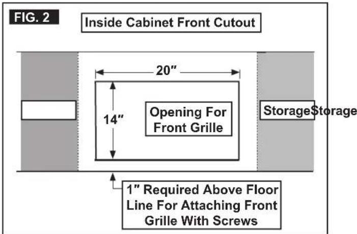
B. Interior Compartment/Sidewall Opening Requirements
- A dedicated interior compartment MUST BE provided for the unit installation. This compartment MUST BE OPEN TO THE OUTSIDE AND AIR SEALED TO THE INSIDE. Interior compartment must be at least 20" deep with an inside cabinet front cutout of 20" x 14". The opening must be 1" above the mounting surface for the unit.
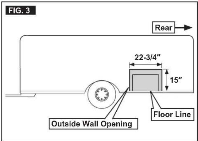
- A 22-3/4" wide x 15" high opening through the sidewall or outside panel is required.
INSTALLATION INSTRUCTIONS
A. Choosing Proper Location For Unit
- The RV manufacturer engineering staff should carefully review each floor plan to determine the best location before starting an installation.

Alternate configurations and methods may be used which still allow the unit to operate properly; however, these alternate configurations and methods MUST be approved by Dometic Corporation.
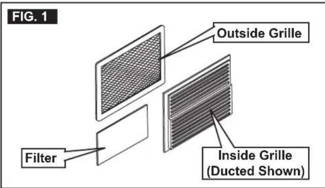
B. Grilles And Registers
The following accessories are available in various kits to simplify installations. See (FIG. 1).
- Indoor direct discharge grille alone, with indoor vents.
- Indoor direct or ducted discharge grille with outdoor grille.
- Indoor direct discharge grille with outdoor grille and outdoor rain shield.
C. Opening Preparation

- ⚠️WARNING FIRE OR ELECTRICAL SHOCK HAZARD. Verify there are no obstacles inside RV's roof and/or walls (wires, pipes, etc.). Shut OFF gas supply, disconnect 120 Vac power from RV, and disconnect positive (+) 12 Vdc terminal from supply battery BEFORE drilling or cutting into RV. Failure to obey these warnings could result in death or serious injury.
- Once the floor plan has been reviewed and the compartment has been selected for unit installation, a 22-3/4" wide by 15" high opening through the sidewall or outside panel is required. The interior compartment must be at least 20" deep. See (FIG. 2) & (FIG. 3).
- Remove the unit from its carton. Inspect for shipping damage.
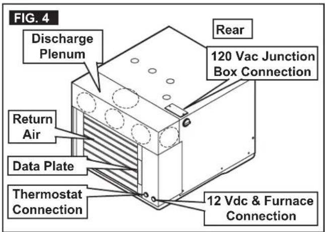
- Locate the discharge air plenum on the unit. Cut the required hole or holes for your installation. The 3 front holes for direct discharge, or the side and/or top holes for ducted applications. See (FIG. 4).
INSTALLATION INSTRUCTIONS

In a travel trailer installation, if within a cabinet or in the ceiling, ducting may be required.
- Interior access openings should be prepared as shown. Cabinet front opening must be 20" wide by 14" high to provide an opening for the discharge and return air grille. The opening must be 1" above the mounting surface of the unit. A discharge and return air grille with register option is available to speed up the installation. An electrical service opening is provided by removing the return air grille. See (FIG. 2).
D. Wiring Requirements
- Route a copper, with ground, 120 Vac supply wire from the time delay fuse or circuit breaker box to the roof opening. Use a listed/certified non metallic - sheathed single strand cable. See "A. Table - Unit Data" on page (5).
- Make sure enough supply wire extends into the compartment to ensure and easy connection at the junction box.
- Protect the wire where it passes into the compartment with approved method.
- Route a dedicated 12 Vdc supply wire (18-22 AWG) from the RV converter (filtered side) or battery to the unit compartment. Make sure enough supply wire extends into the compartment to ensure an easy connection at the unit.
- Route a 3 conductor cable from the compartment to the Liquid Crystal Display Single Zone (hereinafter referred to as LCD SZ) thermostat mounting location. Make sure enough wire extends into the compartment and 6" extends from the wall at the thermostat mounting location. See "E. Choosing Thermostat Location" on page (7).
- If system includes a gas furnace, route two 18 gauge thermostat wires from the furnace to the unit compartment. Make sure enough wire extends into the compartment to ensure an easy connection at the unit.
E. Choosing Thermostat Location
The proper location of the thermostat is very important to ensure that it will provide a comfortable RV temperature. Observe the following rules when selecting a location:
- Locate the thermostat 54" above the floor.
- Install the thermostat on a partition, not on an outside wall.
- NEVER expose it to direct heat from lamps, sun or other heat producing items.
-
Avoid locations close to doors that lead outside, windows or adjoining outside walls.
-
Avoid locations close to supply registers and the air from them.
F. Installing Unit

Hold-down clamps, screws, drain fitting, and sealant used in step 1 & 2 are in hardware kit 3107662.003 and is purchased separately.

- Now that your compartment is ready with all holes cut, carefully slide the unit into position from the outside. Clip the hold-down clamps over the base pan flange and secure in place with screws. See (FIG. 5).
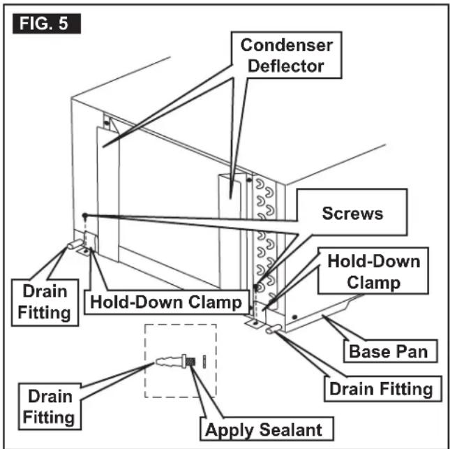
- Next, install the drain fittings in the base pan. Sealant must be added around the threaded end of drain fitting before it is screwed into the base pan. See (FIG. 5).
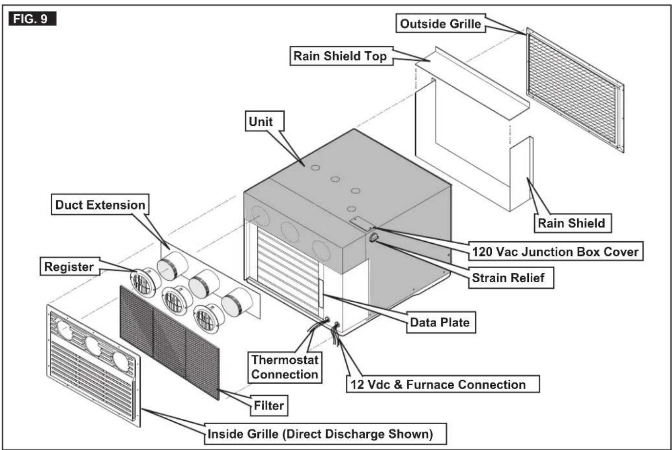
- Install the rain shield. See (FIG. 9).

The rain shield MUST have sealant applied to the short flange surfaces and bottom of the unit, sealing the compartment from rainwater and condensation.
- Seal along the unit bottom to rain shield.
- Using 1/2" plastic tube, (installer supplied) extend the drain fittings through the vent grille or through holes in the bottom of the compartment. Make sure to seal around the tubing where it exits the bottom of the compartment, and that the condensate will drain to the outside of RV.
- Make sure the condenser deflector is against the back of the outside grille. This will decrease recirculation of hot air back into the grille. Install the outside grille. See (FIG. 5) & (FIG. 9).
- The outside work is complete.
INSTALLATION INSTRUCTIONS

If your cabinet space is between 20" and 23-1/2" deep, the metal duct extension is NOT needed. Attach the registers directly to the unit knockout openings. Do NOT insert the registers more than 1/2" into the knockouts. In some installations registers will need to be cut to fit the cabinet space. See "FIG. 9" on page (10) for the order of installation and installation kit component part list.
- After the registers have been installed, install the inside grille to the cabinet front.

When unit is installed with air distribution ducts to carry the conditioned air to remote areas of the interior space, the ducts MUST be sized to maintain a static pressure at the blower outlet between 0.0 and 0.6 inches of water column on high speed.
G. Wiring System
- 120 Vac Power Supply Connection
a. ⚠️WARNING ELECTRICAL SHOCK HAZ-ARD. Verify 120 Vac power is disconnected from RV. Failure to obey this warning could result in death or serious injury.
b. ⚠️WARNING ELECTRICAL SHOCK HAZ-ARD. Provide grounding in compliance with all applicable electrical codes. Failure to obey this warning could result in death or serious injury.
c. Remove junction box cover. See "FIG. 9" on page (10).
d. Route the previously run 120 Vac supply wire through the strain relief and into junction box. Tighten strain relief making sure not to damage wires. Leave enough wire inside junction box to connect to unit 120 Vac wires.
e. Connect the wires in the junction box to the 120 Vac supply wire using appropriate size wire connectors.
• Active to Black
- Neutral to White
- Earth to Green/Yellow
f. Tape the connectors to the supply to ensure they don't vibrate loose.
g. Install junction box cover.
- Low Voltage Wiring Connections
a. NOTICE Verify the positive (+) 12 Vdc terminal is disconnected from supply battery. Otherwise, damage to unit could occur.
b. Connect the previously run +12 Vdc supply wire to the red wire protruding from unit.
c. Connect the previously run -12 Vdc supply wire to both the black wire protruding from the unit and to the wire of the three wire cable that goes to the thermostat 12V- terminal.

The low voltage connection can be made without removing the electrical box cover. The low voltage leads MUST be tucked back inside the electrical box.
d. Connect the previously run furnace wires (if applicable) to the blue/white wires protruding from the unit. The polarity of this connection does not matter.
e. Connect the red/white wire protruding from the unit to the wire of the three wire cable that goes to the thermostat 12V+ terminal.
f. Connect the orange wire protruding from the unit to the wire of the three wire cable that goes to the thermostat COMMS terminal.
H. Thermostat And Communication Cable Installation

Wire colors listed for the communication cable (3 conductor cable) match the wire colors in the unit wire harness. Available wire colors may vary.
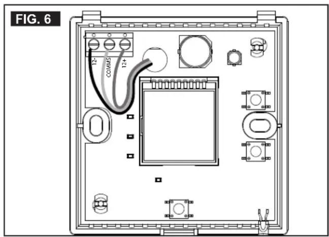
- Remove the cover from the LCD SZ thermostat. Depress tab on bottom of thermostat and separate it from the base.
- Insert the previously run communication cable (3 conductor cable) through the hole in the base assembly.
- Cut back the outer cable shield approximately 3 inches and strip 1/4" insulation from each wire.
- Mount the thermostat level on the wall using the screws provided.
- Make the following connections to the thermostat. See (FIG. 6).
INSTALLATON INSTRUCTIONS
• Red/White wire to the 12V+ terminal
- Black wire to the 12V– terminal
• Orange wire to the "COMMS" terminal
- Inspect all connections to make sure they are tight and not touching any other terminals or wires.
- Push the wires back through the base into the wall. Place cover on the thermostat and push until an audible click is heard.
- This completes the unit installation.
I. System Checkout
- Verify that all features of the system work. See the LCD SZ thermostat Operating Instructions or User's Guide. Reconnect the 12Vdc and 120 Vac power supplies. Check fan speeds, cooling mode, heating mode, and furnace mode (if connected) operation.
If features do not work, disconnect the 120 Vac and 12 Vdc power supplies and verify that all wiring is correct.
WIRING DIAGRAM
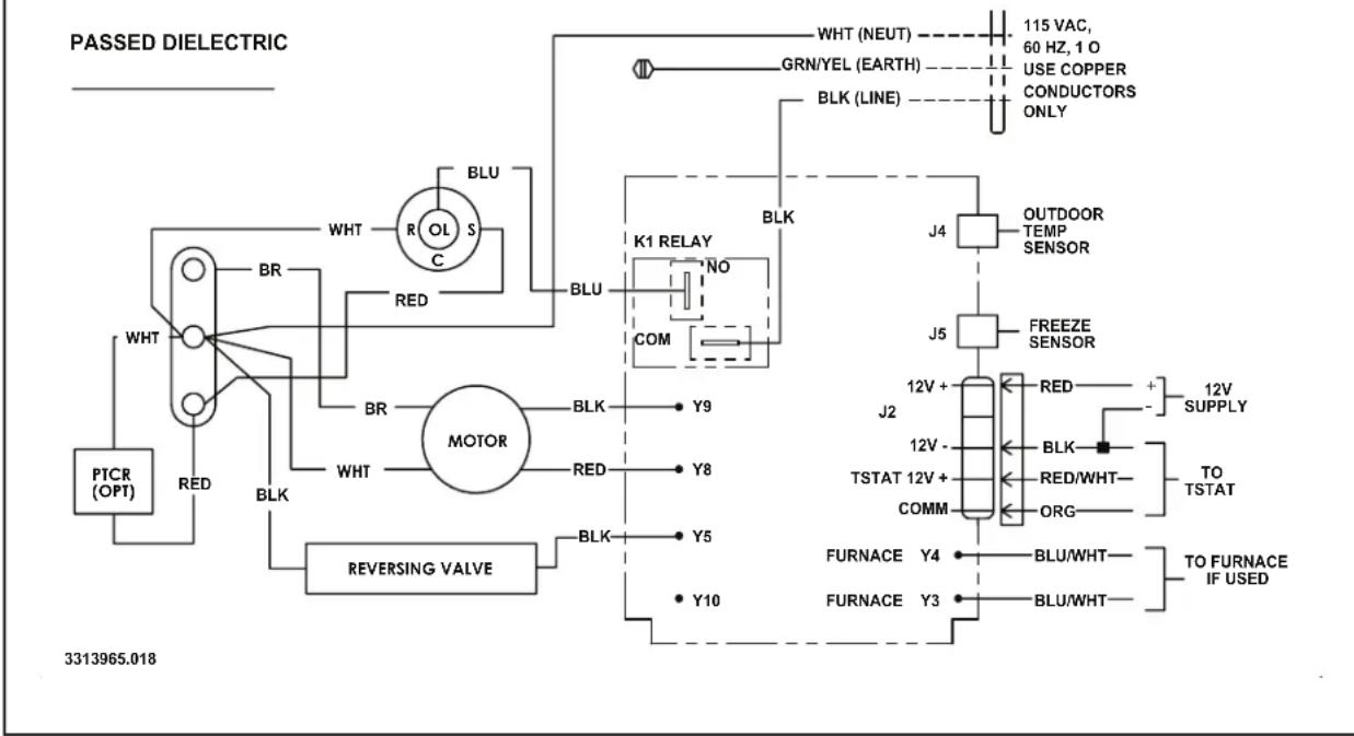
A. Unit Wiring Diagram - Earlier Version
FIG. 7
flowchart
graph TD
    A["PTCR (OPT)"] --> B["RED BLK"]
    B --> C["MOTOR"]
    C --> D["REVERSING VALVE"]
    D --> E["BLK"]
    E --> F["K1 RELAY"]
    F --> G["COM"]
    G --> H["BLK"]
    H --> I["WHT"]
    I --> J["BR"]
    J --> K["RED BLK"]
    K --> L["WHT R OL S C BLU"]
    L --> M["WHT"]
    M --> N["BR"]
    N --> O["RED BLK"]
    O --> P["WHT"]
    P --> Q["BR"]
    Q --> R["RED BLK"]
    R --> S["WHT"]
    S --> T["BR"]
    T --> U["RED BLK"]
    U --> V["WHT"]
    V --> W["BR"]
    W --> X["RED BLK"]
    X --> Y["WHT"]
    Y --> Z["BR"]
    Z --> AA["RED BLK"]
    AA --> AB["WHT"]
    AB --> AC["BR"]
    AC --> AD["RED BLK"]
    AD --> AE["WHT"]
    AE --> AF["BR"]
    AF --> AG["RED BLK"]
    AG --> AH["WHT"]
    AH --> AI["BR"]
    AI --> AJ["RED BLK"]
    AJ --> AK["WHT"]
    AK --> AL["BR"]
    AL --> AM["RED BLK"]
    AM --> AN["WHT"]
    AN --> AO["BR"]
    AO --> AP["RED BLK"]
    AP --> AQ["WHT"]
    AQ --> AR["BR"]
    AR --> AS["RED BLK"]
    AS --> AT["WHT"]
    AT --> AU["BR"]
    AU --> AV["RED BLK"]
    AV --> AW["WHT"]
    AW --> AX["BR"]
    AX --> AY["RED BLK"]
    AY --> AZ["WHT"]
    AZ --> BA["BR"]
    BA --> BB["RED BLK"]
    BB --> BC["WHT"]
    BC --> BD["BR"]
    BD --> BE["RED BLK"]
    BE --> BF["WHT"]
    BF --> BG["BR"]
    BG --> BH["RED BLK"]
    BH --> BI["WHT"]
    BI --> BJ["BR"]
    BJ --> BK["RED BLK"]
    BK --> BL["WHT"]
    BL --> BM["BR"]
    BM --> BN["RED BLK"]
    BN --> BO["WHT"]
    BO --> BP["BR"]
    BP --> BQ["RED BLK"]
    BQ --> BR["WHT"]
    BR --> BS["BR"]
WIRING DIAGRAM
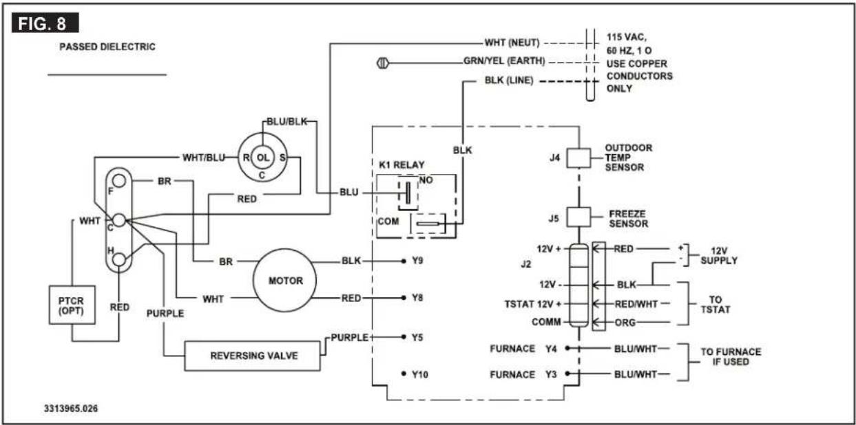
B. Unit Wiring Diagram - Later Version
flowchart
graph TD
    A["PASSED DIELECTRIC"] --> B["WHT/BLU"]
    B --> C["BR"]
    C --> D["RED"]
    D --> E["MOOTOR"]
    E --> F["REVERSING VALVE"]
    F --> G["PURPLE"]
    G --> H["PTCR (OPT)"]
    H --> I["WHT"]
    I --> J["BR"]
    J --> K["RED"]
    K --> L["BLU/BLK"]
    L --> M["OL S"]
    M --> N["K1 RELAY"]
    N --> O["NO COM"]
    O --> P["J4 OUTDOOR TEMP SENSOR"]
    P --> Q["J5 FREEZE SENSOR"]
    Q --> R["J2 12V + RED + 12V SUPPLY"]
    R --> S["J2 12V - BLK - RED/WHT - TO TSTAT"]
    S --> T["COMM"]
    T --> U["FURNACE Y4 BLU/WHT - TO FURNACE IF USED"]
    U --> V["FURNACE Y3 BLU/WHT - TO FURNACE IF USED"]
    V --> W["BLK LINE"]
    W --> X["GRN/YEL (EARTH) 115 VAC, 60 Hz, 1 O USE COPPER CONDUCTORS ONLY"]
INSTALLATION COMPONENTS

- INSTALLATION
- INSTRUCTIONS
- Self-Contained Unit
- Description Model
- INTRODUCTION
- TABLE OF CONTENTS
- DOCUMENT SYMBOLS
- IMPORTANT SAFETY INSTRUCTIONS
- Recognize Safety Information
- Understand Signal Words
- Supplemental Directives
- U.S.A.
- CANADA
- General Safety Messages
- WARNING
- GENERAL INFORMATION
- Required Tools
- Heat Gain
- Unit Functions
- Condensation
- Drain Tube
- Heat Pump Operation
- SPECIFICATIONS
- Interior Compartment/Sidewall Opening Requirements
- INSTALLATION INSTRUCTIONS
- Choosing Proper Location For Unit
- Grilles And Registers
- Opening Preparation
- Wiring Requirements
- Choosing Thermostat Location
- Installing Unit
- Wiring System
- Thermostat And Communication Cable Installation
- INSTALLATON INSTRUCTIONS
- System Checkout
- WIRING DIAGRAM
- Unit Wiring Diagram - Earlier Version
- INSTALLATION COMPONENTS
Brand : DOMETIC
Model : CoolCat
Category : Air-conditioner